

Page 1
Operator’s Manual
RETURN TO MAIN MENU
CHECKPOINT
™
Register your machine:
www.lincolnelectric.com/registration
Authorized Service and Distributor Locator:
www.lincolnelectric.com/locator
Save for future reference
Date Purchased
Code: (ex: 10859)
Serial: (ex: U1060512345)
IM8000 | Issue D ate Aug-13
© Lincoln Global, Inc. All Rights Reserved.
Need Help? Call 1.888.935.3877
to talk to a Service Representative
Hours of Operation:
8:00 AM to 6:00 PM (ET) Mon. thru Fri.
After hours?
Use “Ask the Experts” at lincolnelectric.com
A Lincoln Service Representative will contact you
no later than the following business day.
For Service outside the USA:
Email: globalservice@lincolnelectric.com
Page 2
THANK YOU FOR SELECTING
AT ALL
TIMES.
SPECIAL SITUATIONS
Additional precautionary measures
A QUALITY PRODUCT BY
LINCOLN ELEC TRIC.
PLEASE EXAMINE CARTON AND EQUIPMENT FOR
DAMAGE IMMEDIATELY
When this equipment is shipped, title passes to the purchaser upon
receipt by the carrier. Consequently, Claims for material damaged in
shipment must be made by the purchaser against the transportation
company at the time the shipment is received.
SAFETY DEPENDS ON YOU
Lincoln arc welding and cutting equipment is designed and built with
safety in mind. However, your overall safety can be increased by
proper installation ... and thoughtful operation on your part.
DO NOT INSTALL, OPERATE OR REPAIR THIS EQUIPMENT
WITHOUT READING THIS MANUAL AND THE SAFETY PRECAUTIONS
CONTAINED THROUGHOUT. And, most importantly, think before you
act and be careful.
WARNING
This statement appears where the information must be followed
exactly to avoid serious personal injury or loss of life.
CAUTION
This statement appears where the information must be followed to
avoid minor personal injury or damage to this equipment.
KEEP YOUR HEAD OUT OF THE FUMES.
DON’T get too close to the arc. Use
corrective lenses if necessary to
stay a reasonable distance away
from the arc.
READ and obey the Material Safety
Data Sheet (MSDS) and the warning
label that appears on all containers
of welding materials.
USE ENOUGH VENTILATION or
exhaust at the arc, or both, to keep
the fumes and gases from your breathing zone and the general area.
IN A LARGE ROOM OR OUTDOORS, natural ventilation may be
adequate if you keep your head out of the fumes (See below).
USE NATURAL DRAFTS or fans to keep the fumes away from your
face.
If you de velop unusual symptoms, see your supervisor. Perhaps the
welding atmosphere and ventilation system should be checked.
WEAR CORRECT EYE, EAR & BODY PROTECTION
PROTECT your eyes and face with welding helmet
properly fitted and with proper grade of filter plate
(See ANSI Z49.1).
PROTECT your body from welding spatter and arc
flash with protective clothing including woolen
clothing, flame-proof apron and gloves, leather
leggings, and high boots.
PROTECT others from splatter, flash, and glare with
protective screens or barriers.
IN SOME AREAS, protection from noise may be
appropriate.
BE SURE protective equipment is in good condition.
Also, wear safety glasses in work area
DO NOT WELD OR CUT containers or materials which previously had
been in contact with hazardous substances unless they are properly
cleaned. This is extremely dangerous.
DO NOT WELD OR CUT painted or plated parts unless special
precautions with ventilation have been taken. They can release highly
toxic fumes or gases.
PROTECT compressed gas cylinders from excessive heat, mechanical
shocks, and arcs; fasten cylinders so they cannot fall.
BE SURE cylinders are never grounded or part of an electrical circuit.
REMOVE all potential fire hazards from welding area.
ALWAYS HAVE FIRE FIGHTING EQUIPMENT READY FOR
IMMEDIATE USE AND KNOW HOW TO USE IT.
Page 3
SECTION A:
Diesel Engines
Gasoline Engines
WARNINGS
CALIFORNIA PROPOSITION 65 WARNINGS
Diesel engine exhaust and some of its constituents are known
to the State of California to cause cancer, birth defects, and other
reproductive harm.
The engine exhaust from this product contains chemicals known
to the State of California to cause cancer, birth defects, or other
reproductive harm.
ARC WELDING CAN BE HAZARDOUS. PROTECT
YOURSELF AND OTHERS FROM POSSIBLE SERIOUS
INJURY OR DEATH. KEEP CHILDREN AWAY. PACEMAKER WEARERS SHOULD CONSULT WITH THEIR
DOCTOR BEFORE OPERATING.
Read and understand the following safety highlights. For additional
safety information, it is strongly recommended that you purchase a
copy of “Safety in Welding & Cutting - ANSI Standard Z49.1” from the
American Welding Society, P.O. Box 351040, Miami, Florida 33135 or
CSA Standard W117.2-1974. A Free copy of “Arc Welding Safety”
booklet E205 is available from the Lincoln Electric Company, 22801
St. Clair Avenue, Cleveland, Ohio 44117-1199.
BE SURE THAT ALL INSTALLATION, OPERATION,
MAINTENANCE AND REPAIR PROCEDURES ARE
PERFORMED ONLY BY QUALIFIED INDIVIDUALS.
SAFETY
1.d. Keep all equipment safety guards, covers and
devices in position and in good repair.Keep
hands, hair, clothing and tools away from
V-belts, gears, fans and all other moving parts
when starting, operating or repairing
equipment.
1.e. In some cases it may be necessary to remove safety guards to
perform required maintenance. Remove guards only when
necessary and replace them when the maintenance requiring
their removal is complete. Always use the greatest care when
working near moving parts.
1.f. Do not put your hands near the engine fan. Do not attempt to
override the governor or idler by pushing on the throttle control
rods while the engine is running.
1.g. To prevent accidentally starting gasoline engines while turning
the engine or welding generator during maintenance work,
disconnect the spark plug wires, distributor cap or magneto wire
as appropriate.
1.h. To avoid scalding, do not remove the radiator
pressure cap when the engine is
hot.
ELECTRIC AND
MAGNETIC FIELDS MAY
BE DANGEROUS
2.a. Electric current flowing through any conductor
causes localized Electric and Magnetic Fields (EMF). Welding
current creates EMF fields around welding cables and welding
machines
FOR ENGINE POWERED
EQUIPMENT.
1.a. Turn the engine off before troubleshooting
and maintenance work unless the
maintenance work requires it to be running.
1.b. Operate engines in open, well-ventilated
areas or vent the engine exhaust fumes outdoors.
1.c. Do not add the fuel near an open flame
welding arc or when the engine is running.
Stop the engine and allow it to cool before
refueling to prevent spilled fuel from
vaporizing on contact with hot engine parts
and igniting. Do not spill fuel when filling
tank. If fuel is spilled, wipe it up and do not start engine until
fumes have been eliminated.
2.b. EMF fields may interfere with some pacemakers, and welders
having a pacemaker should consult their physician before
welding.
2.c. Exposure to EMF fields in welding may have other health effects
which are now not known.
2.d. All welders should use the following procedures in order to
minimize exposure to EMF fields from the welding circuit:
2.d.1. Route the electrode and work cables together - Secure
them with tape when possible.
2.d.2. Never coil the electrode lead around your body.
2.d.3. Do not place your body between the electrode and work
cables. If the electrode cable is on your right side, the
work cable should also be on your right side.
2.d.4. Connect the work cable to the workpiece as close as possible to the area being welded.
2.d.5. Do not work next to welding power source.
III
Page 4
SAFETY
ELECTRIC SHOCK
CAN KILL.
3.a. The electrode and work (or ground) circuits are
electrically “hot” when the welder is on. Do
not touch these “hot” parts with your bare skin
or wet clothing. Wear dry, hole-free gloves to insulate hands.
3.b. Insulate yourself from work and ground using dry insulation.
Make certain the insulation is large enough to cover your full area
of physical contact with work and ground.
In addition to the normal safety precautions, if
welding must be performed under electrically
hazardous conditions (in damp locations or while
wearing wet clothing; on metal structures such as
floors, gratings or scaffolds; when in cramped
positions such as sitting, kneeling or lying, if there
is a high risk of unavoidable or accidental contact
with the workpiece or ground) use the following
equipment:
• Semiautomatic DC Constant Voltage (Wire) Welder.
• DC Manual (Stick) Welder.
• AC Welder with Reduced Voltage Control.
3.c. In semiautomatic or automatic wire welding, the electrode,
electrode reel, welding head, nozzle or semiautomatic welding
gun are also electrically “hot”.
3.d. Always be sure the work cable makes a good electrical
connection with the metal being welded. The connection should
be as close as possible to the area being welded.
3.e. Ground the work or metal to be welded to a good electrical (earth)
ground.
3.f. Maintain the electrode holder, work clamp, welding cable and
welding machine in good, safe operating condition. Replace
damaged insulation.
3.g. Never dip the electrode in water for cooling.
3.h. Never simultaneously touch electrically “hot” parts of electrode
holders connected to two welders because voltage
two can be the total of the open circuit voltage of both
welders.
3.i. When working above floor level, use a safety belt to protect
yourself from a fall should you get a shock.
between the
ARC RAYS CAN BURN.
4.a. Use a shield with the proper filter and cover plates to protect your
eyes from sparks and the rays of the arc when welding or
observing open arc welding. Headshield and filter lens should
conform to ANSI Z87. I standards.
4.b. Use suitable clothing made from durable flame-resistant material
to protect your skin and that of your helpers from the arc rays.
4.c. Protect other nearby personnel with suitable, non-flammable
screening and/or warn them not to watch the arc nor expose
themselves to the arc rays or to hot spatter or metal.
FUMES AND GASES
CAN BE DANGEROUS.
5.a. Welding may produce fumes and gases
hazardous to health. Avoid breathing these
fumes and gases. When welding, keep your head out of the fume.
Use enough ventilation and/or exhaust at the arc to keep fumes
and gases away from the breathing zone. When welding
with electrodes which require special ventilation
such as stainless or hard facing (see instructions
on container or MSDS) or on lead or cadmium
plated steel and other metals or coatings which
produce highly toxic fumes, keep exposure as low
as possible and within applicable OSHA PEL and
ACGIH TLV limits using local exhaust or
mechanical ventilation. In confined spaces or in
some circumstances, outdoors, a respirator may
be required. Additional precautions are also
required when welding on galvanized steel.
5. b. The operation of welding fume control equipment is affected by
various factors including proper use and positioning of the
equipment, maintenance of the equipment and the specific
welding procedure and application involved. Worker exposure
level should be checked upon installation and periodically
thereafter to be certain it is within applicable OSHA PEL and
ACGIH TLV limits.
5.c. Do not weld in locations near chlorinated hydrocarbon vapors
coming from degreasing, cleaning or spraying operations. The
heat and rays of the arc can react with solvent vapors to form
phosgene, a highly toxic gas, and other irritating products.
3.j. Also see It ems 6.c. and 8.
5.d. Shielding gases used for arc welding can displace air and
injury or death. Always use enough ventilation, especially in
confined areas, to insure breathing air is safe.
5.e. Read and understand the manufacturer’s instructions for this
equipment and the consumables to be used, including the
material safety data sheet (MSDS) and follow your employer’s
safety practices. MSDS forms are available from your welding
distributor or from the manufacturer.
5.f. Also see item 1.b.
IV
cause
Page 5

SAFETY
WELDING AND CUTTING
SPARKS CAN CAUSE
FIRE OR EXPLOSION.
6.a. Remove fire hazards from the welding area. If
this is not possible, cover them to prevent the
welding sparks from starting a fire. Remember that welding
sparks and hot materials from welding can easily go through
small cracks and openings to adjacent areas. Avoid welding near
hydraulic lines. Have a fire extinguisher readily available.
6.b. Where compressed gases are to be used at the job site, special
precautions should be used to prevent hazardous situations.
Refer to “Safety in Welding and Cutting” (ANSI Standard Z49.1)
and the operating information for the equipment being used.
6.c. When not welding, make certain no part of the electrode circuit is
touching the work or ground. Accidental contact can cause
overheating and create a fire hazard.
6.d. Do not heat, cut or weld tanks, drums or containers until the
proper steps have been taken to insure that such procedures will
not cause flammable or toxic vapors from substances inside.
They can cause an explosion even though they have been
“cleaned”. For information, purchase “Recommended Safe
Practices for the Preparation for Welding and Cutting of
Containers and Piping That Have Held Hazardous Substances”,
AWS F4.1 from the American Welding Society (see address
above).
6.e. Vent hollow castings or containers before heating, cutting or
welding. They may explode.
6.f. Sparks and spatter are thrown from the welding arc. Wear oil free
protective garments such as leather gloves, heavy shirt, cuffless
trousers, high shoes and a cap over your hair. Wear ear plugs
when welding out of position or in confined places. Always wear
safety glasses with side shields when in a welding area.
6.g. Connect the work cable to the work as close to the welding area
as practical. Work cables connected to the building framework or
other locations away from the welding area increase the
possibility of the welding current passing through lifting chains,
crane cables or other alternate circuits. This can create fire
hazards or overheat lifting chains or cables until they fail.
6.h. Also see item 1.c.
CYLINDER MAY EXPLODE IF
DAMAGED.
7.a. Use only compressed gas cylinders containing
the correct shielding gas for the process used
and properly operating regulators designed for
the gas and pressure used. All hoses, fittings,
etc. should be suitable for the application and
maintained in good condition.
7.b. Always keep cylinders in an upright position securely chained to
an undercarriage or fixed support.
7.c. Cylinders should be located:
• Away from areas where they may be struck or subjected
to physical damage.
• A safe distance from arc welding or cutting operations
and any other source of heat, sparks, or flame.
7.d. Never allow the electrode, electrode holder or any other
electrically “hot” parts to touch a cylinder.
7.e. Keep your head and face away from the cylinder valve outlet
when opening the cylinder valve.
7.f. Valve protection caps should always be in place and hand tight
except when the cylinder is in use or connected for use.
7.g. Read and follow the instructions on compressed gas cylinders,
associated equipment, and CGA publication P-l, “Precautions for
Safe Handling of Compressed Gases in
Cylinders,” available
from the Compressed Gas Association 1235 Jefferson Davis
Highway, Arlington, VA 22202.
FOR ELECTRICALLY
POWERED EQUIPMENT.
8.a. Turn off input power using the disconnect
switch at the fuse box before working on the
equipment.
8.b. Install equipment in accordance with the U.S. National Electrical
Code, all local codes and the manufacturer’s recommendations.
6.I. Read and follow NFPA 51B “ Standard for Fire Prevention During
Welding, Cutting and Other Hot Work”, available from NFPA, 1
Batterymarch Park, PO box 9101, Quincy, Ma 022690-9101.
6.j. Do not use a welding power source for pipe thawing.
8.c. Ground the equipment in accordance with the U.S. National
Electrical Code and the manufacturer’s recommendations.
Refer to
http://www.lincolnelectric.com/safety
for additional safety information.
Welding Safety
Interactive Web Guide
for mobile devices
V
Page 6

NOTES
Page 7

Table of Contents
Preface
Typographical Conventions Used ........................................................................................................ 1
Cross-References ....................................................................................................................... 1
Text You Type Using the Keyboard ............................................................................................ 1
Keys You Press and Buttons You Click ........................................................................................ 1
Menus You Select .............................................................................................................. ........ 1
Dialog Box, Application Window Titles, a nd F ield Name s .......................................................... 1
Notes, Warnings, and Tips ................................................................................................................... 2
Revision History
General Informa t io n
Introduction to CheckPoint™ ............................................................................................................ 1.1
CheckPoint™ Editions.............................................................................................................. 1.1
Weld Profiles ........................................................................................................................... 1.2
Weld Logging .......................................................................................................................... 1.2
Electronic Notificat ion S yste m ................................................................................................ 1.3
Traceability ............................................................................................................................. 1.3
Mobile Devices........................................................................................................................ 1.4
WeldScore™ ..................................................................................................................................... 1.4
CheckPoint™ Cloud-Based Architecture ........................................................................................... 1.4
Security and Da ta Storage ................................................................................................................ 1.5
Requirements and Network Capacity ............................................................................................... 1.5
Access Requirements .............................................................................................................. 1.5
Accessing Data in the CheckPoint ™ Data Center .................................................................... 1.5
Network Capacity .................................................................................................................... 1.6
Preparing for CheckPoint™
Providing Access to the Internet ....................................................................................................... 2.1
Update the Welding Power Source Firmw a re .................................................................................. 2.1
Install the Latest Power Wave® Manager ......................................................................................... 2.4
Enable CheckPoint™ for a Power Source .......................................................................................... 2.6
Establish Connection to the Welding Pow er Source ............................................................... 2.6
Enabling CheckPoint™ ............................................................................................................. 2.8
Save the Production Monitoring Installat ion Key F ile ........................................................... 2.10
Setting up CheckPoint™
Connecting to CheckPoint™ .............................................................................................................. 3.1
Create Administrato r Account .......................................................................................................... 3.2
Validate User Information in Chec kPoint ™ ....................................................................................... 3.3
IM8000 CheckPoint™User Manual TOC.1
Page 8

Table of Contents
Uploading the Installat ion Key File ................................................................................................... 3.4
Register Your Company .................................................................................................................... 3.5
Creating Multiple Site s ..................................................................................................................... 3.7
Managing CheckPoint™
Tabs in the CheckPoint™ Manager ................................................................................................... 4.1
Filtering Lists in the CheckP oint™ Manager ...................................................................................... 4.2
General Tab ...................................................................................................................................... 4.3
Company Information ............................................................................................................. 4.3
Allowable IP Addresses ........................................................................................................... 4.3
User Management ............................................................................................................................ 4.4
Display Current Users ............................................................................................................. 4.4
Add a User Account ................................................................................................................ 4.5
Edit a User Account ................................................................................................................. 4.6
Delete a User Account ............................................................................................................ 4.7
Shift Schedules ................................................................................................................................. 4.8
Next Production Day ............................................................................................................... 4.8
Add a Shift............................................................................................................................... 4.9
Edit a Shift .................................................................................................................. ........... 4.13
Remove a Shift ...................................................................................................................... 4.13
Shift Schedule Exa mple – Three Basic Shift s ......................................................................... 4.13
Shift Schedule Exa mple – Two Alternating Shifts, No Weekends .......................................... 4.15
Welding Power Sources .................................................................................................................. 4.17
Site Configurat ion and Overall Equipment Efficiency (OEE) .................................................. 4.19
Adding a Container ............................................................................................................... 4.20
Adding a Welding Power Source ........................................................................................... 4.21
Changing the Container for a Welding Power Sourc e ........................................................... 4.23
Alert History ................................................................................................................................... 4.24
Documents ..................................................................................................................................... 4.25
Access and Navigate the Library ........................................................................................... 4.25
Add a Document to the Library ............................................................................................. 4.26
Add a Link to the Document Library ..................................................................................... 4.28
Your CheckPoint™ User Account
Finalize User Registra t ion ................................................................................................................. 5.1
Accept the End-User License Agreeme nt ................................................................................ 5.1
Confirm Security Settings ........................................................................................................ 5.2
Managing Your User Account ........................................................................................................... 5.2
Notifications............................................................................................................................ 5.3
Personal Information .............................................................................................................. 5.3
Password Change .................................................................................................................... 5.4
play Preferenc e s ................................................................................................................ 5.4
Dis
Daily Digest ............................................................................................................................. 5.5
TOC.2 CheckPoint™ User Manual IM8000
Page 9

Overview
Navigating CheckPoint ™ ................................................................................................................... 6.1
Overview of Reports ......................................................................................................................... 6.4
Table of Contents
Alert Subscriptions .................................................................................................................. 5.6
Site Membership ..................................................................................................................... 5.9
Asset Tree ............................................................................................................................... 6.1
Report Tabs ............................................................................................................................. 6.2
Individual Reports ................................................................................................................... 6.3
Panel Resize ............................................................................................................................ 6.3
Generating Reports ................................................................................................................. 6.4
Report Criteria ........................................................................................................................ 6.4
Report Links ............................................................................................................................ 6.5
Sorting by Columns ................................................................................................................. 6.6
Report Page Numbers ............................................................................................................. 6.6
Exporting Report Data ............................................................................................................ 6.7
Refreshing Report Data ........................................................................................................... 6.7
Summary Tab – Container Level
Equipment Reports ........................................................................................................................... 7.1
Operator Reports .............................................................................................................................. 7.4
Overview Reports ............................................................................................................................. 7.6
Utilization................................................................................................................................ 7.6
Productivity ............................................................................................................................. 7.7
Lowest Consumable Time Remaining ..................................................................................... 7.8
WeldScore™ ............................................................................................................................ 7.8
Avg. WeldScore™ Top 10 and Avg. WeldScore™ Bottom 10 ................................................... 7.9
Summary Tab – Power Source Level
Today ................................................................................................................................................ 8.1
Status ...................................................................................................................................... 8.2
Availability (Last 24 H our s)...................................................................................................... 8.3
Consumable Package .............................................................................................................. 8.5
Serial Numbers........................................................................................................................ 8.6
Utilization (Last 24 H our s) ....................................................................................................... 8.7
WeldScore™ Live Update ........................................................................................................ 8.7
Welder Detail .......................................................................................................................... 8.8
Productivity (Last 24 Hours) .................................................................................................... 8.9
ldScore™ (Last 24 Hours) ................................................................................................. 8.10
We
Last 7 Days ...................................................................................................................................... 8.10
Utilization (Last 7 Da ys)......................................................................................................... 8.10
Productivity (Last 7 Days) ...................................................................................................... 8.11
WeldScore™ (Last 7 Days) ..................................................................................................... 8.12
Avg. True Energy™ in Kilojoules (7 Days) .............................................................................. 8.13
IM8000 CheckPoint™ User Manual TOC.3
Page 10

Table of Contents
Custom ........................................................................................................................................... 8.14
Overall Equipment Efficiency (OEE)
OEE Tab ............................................................................................................................................ 9.1
Today Reports ......................................................................................................................... 9.2
Last 7 Days .............................................................................................................................. 9.3
Custom .................................................................................................................................... 9.4
Calculations of OEE in CheckP oint ™ ................................................................................................. 9.5
OEE Percentage....................................................................................................................... 9.5
Availability Fac t or ................................................................................................................... 9.5
Performance Factor ................................................................................................................ 9.8
Quality Factor ......................................................................................................................... 9.9
Establishing Planned Downt ime ..................................................................................................... 9.10
Planned Downtime Example ................................................................................................. 9.11
Adding Planned Downtime ................................................................................................... 9.11
Planned Downtime – Company Site ...................................................................................... 9.13
Planned Downtime – Container ............................................................................................ 9.14
Planned Downtime – Welding Power Source ....................................................................... 9.15
Assembly Li sting Tab
Overview Report ............................................................................................................................. 10.1
Main Overview List ............................................................................................................... 10.1
Overview Drilldown .............................................................................................................. 10.3
Weld Sequence Drilldown ..................................................................................................... 10.5
By Assembly.................................................................................................................................... 10.6
Weld Listing Tab
Summary Report............................................................................................................................. 11.1
Summary Criteria .................................................................................................................. 11.1
Data on the Report ............................................................................................................... 11.3
Weld Detail ........................................................................................................................... 11.5
Weld Profiles ................................................................................................................................ 11.10
Profile Reports .............................................................................................................................. 11.11
Criteria on the Profile Report s ............................................................................................ 11.12
WeldScore™ ........................................................................................................................ 11.13
Current/Voltage .................................................................................................................. 11.13
Wire Feed Speed ................................................................................................................. 11.13
Deposition ........................................................................................................................... 11.13
True Energy™ ...................................................................................................................... 11.14
Duration .............................................................................................................................. 11.14
ount .................................................................................................................................. 11.14
C
TOC.4 CheckPoint™ User Manual IM8000
Page 11

Limit Errors Tab
Overview ........................................................................................................................................ 12.1
Today .............................................................................................................................................. 12.1
Last 7 Days ...................................................................................................................................... 12.2
Custom ........................................................................................................................................... 12.2
Events Tab
Report Criteria ................................................................................................................................ 13.2
Summary ........................................................................................................................................ 13.3
History ............................................................................................................................................ 13.4
Documents Tab
Opening Documents and Links ....................................................................................................... 14.1
Operators Manuals ......................................................................................................................... 14.2
Troubleshooting
Cannot Connect to a Power Source ................................................................................................. A.1
Cannot Apply Settings ..................................................................................................................... A.1
Table of Contents
Overall Equipment Efficiency Examples
Availability Example 1 .......................................................................................................................B.1
Availability for Eac h Hour ........................................................................................................B.2
Availability for the Entir e Shift ................................................................................................B.2
Availability Example 2 .......................................................................................................................B.2
Availability for Eac h Hour ........................................................................................................B.3
Availability for the Entir e Shift ................................................................................................B.3
Availability Example 3 .......................................................................................................................B.4
Availability for Eac h Hour ........................................................................................................B.4
Availability for the Entir e Shift ................................................................................................B.5
Glossary
IM8000 CheckPoint™ User Manual TOC.5
Page 12

Table of Contents
TOC.6 CheckPoint™ User Manual IM8000
Page 13

Preface
Typographical Conventions Used
Before using this guide, it is importa nt to understa nd t he typographic al conventions used to identify and
describe information.
Cross-References
Cross-references t o chapter s, sections, page numbers, hea dings, e t c . a re shown in a n italic t yp e fa ce .
e.g., Refer to Text You Type Using the Keybo ard on page 1.
Text You Type Using the Keyboard
Text that you type using the keyboard is shown in a Courier typeface.
e.g., Type John Smi th in t he Name field.
Keys You Press and Buttons You Click
Keys tha t you press on the key board and buttons/icon s that you click with the mouse are shown in a bold
sans-serif t y peface.
e.g., Press Enter.
e.g., Click OK to continue.
Menus You Select
Menus and the selections you make from the menus are shown in a bold sans-serif typeface.
e.g., Select Start > Control Panel from the main computer menu.
e.g., Select Tools > Options from the menu.
Dialog Box, Application Window Titles, and Field Names
The titles of dialog boxes and application windows are shown in italics. Field names and selections made
from drop-down menus, etc. are also shown in italics.
e.g., The Print Preview window opens.
e.g., Select All Shifts from the drop-down list.
IM8000 CheckPoint™User Manual 1
Page 14

Preface Notes, Warnings, and Tips
Notes, Warnings, and Tips
Notes, stops and tips appear throughout the manual. They provide additiona l informa t ion t hat is important
for you to know about the topic.
NOTE | A note is a n important piece of information.
STOP | You should definitely read the informatio n in a stop table.
It could help y ou prevent a situation from which you cannot
recover.
TIP | A tip table helps you w it h s ome interesting or useful
informatio n about using the program.
2 CheckPoint™ User Manual IM8000
Page 15

Revision Histor y
Date Change Description
August 2012 Initial release a s IM8000
June 2013 Major revamp and update of manual
August 2013 Made the following updates reflecting t he new ver sion:
Added Overall Equipment Efficiency (OEE)features to setup instructions
Updated description of Daily Digest to reflect check mark behavior
Edited User Time/Company time descriptions for shifts
Edited chapters to reflect Summary tab changes
Added new OEE tab section
Added new Assembly Listing tab section
Updated screenshots to reflect new tabs, features and changes
IM8000 CheckPoint™User Manual REV.1
Page 16

Revision History
THIS PAGE INTENTIONALLY LEFT BLANK.
REV.2 CheckPoint™ User Manual IM8000
Page 17

Chapter 1
General Information
Introduction to CheckPoint™
CheckPoint™ is the newest data collection and repo r ting technology available for the latest models of t he
Lincoln Electric P owe r Wave® family of Welding Power Sources.
CheckPoint™ is cloud-based co mput ing ba sed on Production Monit or ing™ but with mor e funct ionalit y a nd
more flexibility. C he ckPoint™ does not require additional har dwa r e or softw are installation, allowing you
to work from you own computer using your Internet browser. CheckPoint™ enables you to measure the
Pulse™ of your Lincoln Electr ic ® welders with critical alerts and unpr ece de nte d pr oduction visibilit y.
CheckPoint™ is available for viewing on your smart phone, tablet and laptop or desktop of any computer or
device with Internet access.
Cloud-based computing refer s to the delive r y of computing a nd storage capacity a s a service to a
community of end users. End users access cloud-based applications through a web br owser or a desktop or
mobile app while the business software a nd data ar e store d on server s at a remote location. Cloud
computing allows compa nie s to get applications up and running faster, with improved manage a bilit y and
less maintenance. It relies on sh a ring of resources t o achieve coherence and economies of sca le similar to a
utility (like th e electricity grid) over a networ k (typ ic ally the Internet).
CheckPoint ™ allow s gr e a ter visibility. You can access your data anytime, anywhere, with any web device
without the need for VPN client software. CheckPoint ™ is ea sy to implem e nt and mainta in. You simply
plug the Welding Power Source into your network. (Refer to the Power Wave® Manager User Manual for
instructions.) There is low ove r hear d a nd no computer hardware required in the field; it is as user-friendly
as going to a website. CheckPoint™ is more dynamic in t ha t any updat e s to the applicat ion’s func t iona lit y
are instant across all users.
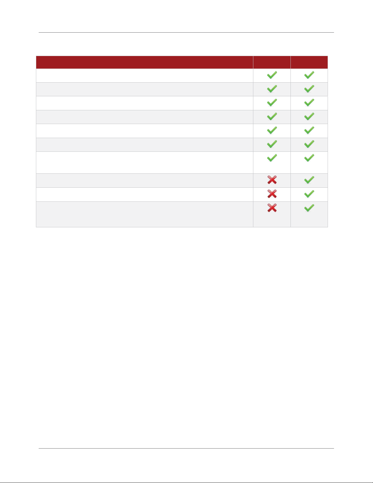
CheckPoin t ™ Editions
CheckPoint™ offers two options: Standard E dit ion and Premium Edition. The Standard Edition is available
free of charge w it h eve r y Powe r Wa ve®. Sta ndar d Edition includes a rolling 30 days of data storage after
which point the data is permanent ly de lete d from the system. The Premium Edition is available for an
annual subscription fee , w hich includes a rolling 12 months of data storage with a permanent offline
archive. With CheckPoint™, it is possible to have a combina tion of Standard and Premium Editions based
on your needs. Table 1.1 details the differ ences in features.
NOTE | For details on the Premi um Edition, please send a n e-mail
with your conta c t information to sales@igearonline.com
.
IM8000 CheckPoint™User Manual 1.1
Page 18
Chapter 1. General Information Introduction to CheckPoint™
Table 1.1 Features in Each Versi on
Field Standard Premium
Mobile Ready, Global Data Access
Cloud Ready, Global Data Access
E-mail Notification System
Reporting
Manual Data Export
Document Library
Extended Document Library
(Upload and store up to 15 GB of custom documents and files)
1 Year of Live Rolling Data Storage
Automated Data Archiving
Share Data wit h Third-P a r ty Applications and Systems
(with ODATA API)
Weld Profiles
One of the principal goals of CheckPoint™ is to report on welds that are outside of user-defined limits with
respect to WeldScore™, current, voltage, wire feed speed and duration. This goal would be simple to
implement if th e Welding P o w e r So ur ce we r e to per for m on ly on e t y pe of we ld ov e r and over. H owe ver, in
practical applicat ions, t his is not the case. The assembly of many different industrial components re quires
welds of varying type and length .
The concept of Weld Pr o file s allows the Welding Power Source to apply differ ent limit settings for each
weld that is performed on a certain part. Before the Welding Power Source begins a new weld, the wire
feeder or system controller selects the corresponding Weld Profile. The Weld Engineer can, therefore,
assign one Weld P r o file to each weld required for the part asse m b ly.
For more in-dept h info r ma tion about Weld Profiles, please refer to the Power Wave® Manager User
Manual.
Weld Logging
CheckPo int ™ records large quantities of weld statistics. Each log entry contains th e fo llowing welding
statistics for each weld:
For current, voltage, wire feed speed and duration:
- Minimum
- Maximum
- Average
- Percent above limit
1.2 CheckPoint™User Manual IM8000
Page 19

Introduction to CheckPoint™ Chapter 1. General Information
- Percent belo w lim it
- Profile ma ximu m limit
- Profile minimum lim it
True Energy™
Date and time the weld was made
Duration of the weld
Weld stat us a f te r limit checking
Part Number, Consumable Lot and Operator ID
WeldScore™
Electronic Notificat ion System
When a Welding Power Source is used with CheckPoint ™, t he data center can send e-mail and text-message
notifications to multiple use r s. Eac h user’s e-mail a ddr e ss and mobile numbe r can be configur e d t o receive
messages from the CheckPoint™ data center upon any of several e ve nt condit ions. See page 5.6 for more
details on the alerts available.
Traceability
CheckPoint ™ pr o vides you with the ability t o repo r t on all the welds that were made on a specific part
number, by a specific o per ator or using a specific consumable lot c ode. Before a w e ld is made , this
information is communic ated to the Welding Power Source, in a variety of ways. Every weld that is ma de
after this is assigned with these ID numbe r s until a ne w number is e ntered. CheckP oint ™ users can
generate a traceability report that looks fo r this ID from a ll t h e W e lding Power Sources in the system.
Traceability solutions are typica lly c u stomized to a customer’s specific needs. Please contact Linco ln
Electric for a quote on your needs.
NOTE | CheckPoint™ does not s upport consumable package
tracking f or dual wire feeding syst ems .
IM8000 CheckPoint™ User Manual 1.3
Page 20
Chapter 1. General Information WeldScore™
Mobile Devices
With CheckPoint™, you can download native apps for iPhone®, Bla ckbe r r y® and Android t o provide mobile
users access to their welder data anytime from anywhe re. Users can view da shboa rd widget s, history a nd
alarm events, receive real-time text and e-mail messages, download the latest documents, and scan
barcodes a s part o f an ea sy-to-use traceability solution.
Links for downloading m o bile a pplic ations are available at www.lincolncheckpoint.com under the Mobile
Enabled portion of the home page. For more information on using the mobile version, please refer to the
CheckPoint™ Mobile App User Manual.
WeldScore™
WeldScore™, a new fe atur e ava ila ble in all third-generation Welding Power Sour ce mo de ls (including the
i400, C300, S350, S500 and AC/DC 1000 SD), can be used to support a weld qua lity control program. It
assigns a scor e to welds on a 0% to 100% scale that indicates the acceptability of the weld. The score is
based on a comparison to previously trained welding condit ions. Any weld w ith a score of 85% to 90% or
above can be considered, with a reasonable amount of confidence, to be an acceptable weld. WeldScore™
can be used independently on the power source or together with CheckPoint™. Please refer to the Power
Wave® Manager User Manual for more in-depth information on WeldScore™.
NOTE | WeldScore™ is not a guarantee of quality and is not
intended t o replace a quality co ntrol system.
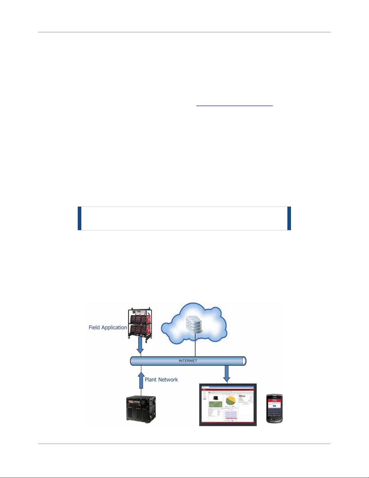
CheckPoint™ Cloud-Based Architecture
The CheckPoint™ system uses a cloud-based ar c hit e ctur e . This means that ther e is no dedicate d compute r
required at your company to collect and store the data. Each piece of welding e quipme nt simply require s a
network connection. The Welding P o w e r Source initiates the transfer of information through firewallfriendly communications to the data center. (The data transfer does not initiat e fr om outside the power
source.) At that point, the data is accessible using a w e b brow se r and a secure login.
Figure 1.1 CheckPoint™ Cloud-Based Architecture
1.4 CheckPoint™User Manual IM8000
Page 21

Security and Data Storage Chapter 1. General Information
Security and Data Storage
Each CheckPoint™ customer’s data is stored in a state-of-the -art data cent e r in dedicate d and par t it ione d
databases, exclusive t o eac h custome r . Additionally, when viewing the CheckPoint™ application, highsecurity, industr y-st andard encryption is utilized.
The hosting cent er is a SAS 70 Ty pe II c om pliant fa c ility. SAS 70 is designated by the U.S. Securities and
Exchange Commission (SEC) as an acceptable method to obtain assurance of a service organization’s
internal controls without c o nducting separ ate assessment s. Suc c essful complet ion of t he SAS 70 Type II
examination indicat es that the processes, procedures, and contro ls have been formally e valuate d and
tested by an independent auditing firm.
A service auditor ’s exa minat ion pe r formed in accordance with SAS No. 70 (SAS 70 audit) is widely
recognized. It represents that a service orga nization ha s bee n thro ugh a n in-depth audit of the ir contr ol
objectives and control act ivit ies, w hic h oft e n include c ontrols over information technology and related
processes. A Type II report not only includes the service organiza t ion’s descr iption of c o nt rols but also
includes detaile d testing of the design and operating effec t iveness.
The hosting center environme nt is built w it h stat e-of-t he-art equipment, technology investments and
operational expert ise . The re is an esta blished disa ster recovery program with redundancy and failover to
protect the information stored in the system.
Requirements and Network Capacity
Access Requ irements
Each computer or mobile device that wants to conne ct t o CheckPoint™ must have access to the Inte r net.
All Welding Power Sources also need to have access to the Internet to report information back to the
CheckPoint™ data center . Every Welding Power Sourc e has a unique 16-charact er serial number.
This identification serial number is save d dur ing the registra t ion pr ocess and sent to the CheckPoint™ data
center with each welding data packet. When data arrives at the CheckPoint™ data center, the identification
serial number is used to save the data into your customer database.
See Chapter 2 for details on preparing for CheckPoint™.
Accessing Dat a in the CheckPoint™ Data Center
Each customer has a separate partition in the database for the ir data . You control acce ss to your data with
usernames and passwords that are created by your CheckPoint™ Administrator. The administrator
provides access to the data, as needed, for those users who need to access the data and generate reports.
See page 4.4 for details on User Management.
IM8000 CheckPoint™ User Manual 1.5
Page 22

Chapter 1. General Information Requirements and Network Capacity
Network Cap acity
Networks and Internet connections have a limited amount of bandw idt h for sending dat a . Each Welding
Power Source uses a small amount of bandwidth. In order to estimate the total ba ndw idt h on your
network, you can multiply the number of power welding source s by the data qua ntit y of data pack ets
described:
Every 20 seconds, each power source sends a status update to the Chec kP oint ™ data center; th e
data packet is about 1 KB in size.
If a power source has completed a weld, or multiple welds, ever y 92 seconds it will send the new
data; the data packet is about 2 KB per weld.
If there is an oc c urr e nce of a powe r so ur c e e vent o r fault , every 66 seconds it w ill se nd the new
data; the data packet is 0.5 KB in size per event.
In the event the network or Internet connection goes down due to unexpected problems or scheduled
maintenanc e , the Welding Power Sources will continue to c ollect and hold the welding data until the
network connection is reest a blished.
Each power source has enough internal memory to hold welding da t a for 1000 welds. Once t he Interne t
connection is r eest ablished, all welding data will be sent to the CheckPoint™ data center. If more than
1000 welds are made before the Internet connect ions is ree st a blished, only the data from the la st 1000
welds will be saved; data for the oldest welds will be lost.
STOP | If the power source is turned off before the Internet
connecti on is reestablished, al l w e lding data will be lost.
1.6 CheckPoint™ User Manual IM8000
Page 23
Chapter 2
Preparing for CheckPoint™
It is essential to have at least one Welding Power Source set up in CheckPoint ™ pr ior to creating a n acc ount
for your company. This chapt er walks you through t h e necessary step s to c omplete this task. Af ter
successfully c om pleting these steps, you will becom e the Che ckPoint™ Site Administrator and have the
ability to add Welding P o w e r So ur ces a nd user s through the CheckPoint™ Manager function of the
application.
Providing Access to the Internet
You need to open up the following information on your server in order to grant the Welding P ow er S ources
access to the Internet: http://ws.lincolncheckpoint.com at IP address 216.26.175.3 (subject to change)
using port 80 to send out TCP/IP and HTTP messages.
TIP | Contact y our local IT department for assistance.
Update the Welding Power Source Firmware
“Firmware ” is th e memo r y and programming code within the Welding Power So ur ce t hat is the co nt r o l
program for the machine. Making sure you have the latest firmware ensures that you have the latest
features available for the power source, inc luding th e most rec e nt ver sion of the Production Monitoring™
and CheckPoint™ software .
To install the latest firmware:
Procedure Details
1. Log in to the computer as a user with
administrat ive pr ivileges.
2. Open your browser and go to
www.powerwavesoftware.com.
3. Enter your username and password in the Email
and Password fields and click Sign In.
OR
Click the Register Today link to create an
account.
Contact your IT department if you do not have
administrat o r pr ivile ges.
The Login page displays.
If you’re creating a new account, follow t he
onscreen instructions and return to this st ep
when finished.
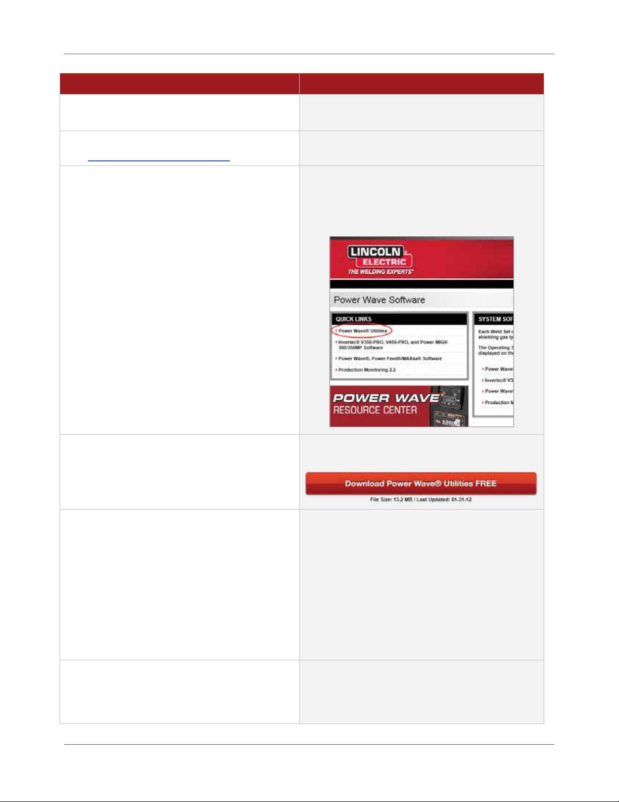
Once yo u log in , t h e system displays the Power
Wave Resource Center.
IM8000 CheckPoint™User Manual 2.1
Page 24
Chapter 2. Preparing for CheckPoint™ Update the Welding Power Source Firmware
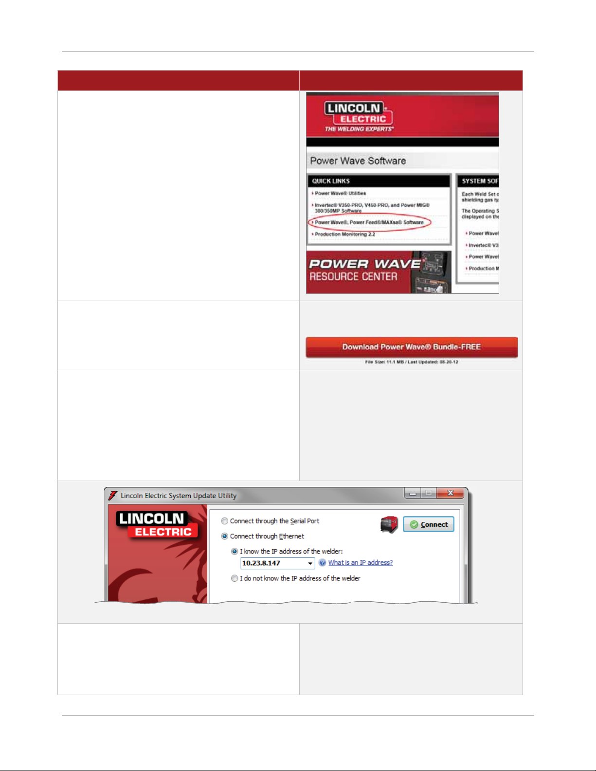
Procedure Details
4. In the Quick Li n k s se c tion, click the Power
Wave®, Power Feed®/MAXsa® Software link.
5. Click the Download Power Wave® Bundle-FREE
button to run the update.
The system displays a page co ntaining t he
Download Power Wave® Bundle-FREE button.
NOTE | Depending on your Windows version,
you may have to click Run or Allow to permit
your system to launch the file.
The system opens the Lincoln Electric System
Update Utility window where you tell t he ut ility
how to find the Welding Power Source you want
to update.
6. Choose the Connect through E thernet option
and enter the IP address of the Welding Power
Source you want to update.
2.2 CheckPoint™User Manual IM8000
TIP | If there is an IP address a lready
displaye d, it is the IP address of the las t
Welding Pow er Source that wa s c onnected.
Be sure you enter the correct address f or t he
current We lding Power Source you w a nt t o
Page 25

Update the Welding Power Source Firmware Chapter 2. Preparing for CheckPoint™
Procedure Details
update.
You can enter the IP address for the Welding
Power Source in one of two ways:
Type the specific IP address into t he I
know the IP address of the welder field.
Choosing the I do not know the IP
address of the welder option. The
update utility scans your network and
displays a list of W e lding P o w er Source
IP addresses on the same subnet.
NOTE | If this Welding P ow er Source has
older firmware, the IP address will not show up
using this method.
TIP | If you run into a problem, please refer to
the Troubleshooting section (0).
7. Click the Connect button once you have
entered the IP address for the power source
you are updating.
The soft ware scans the We ld in g Power Source to
verify if the firmware currently on the machine
is up to date.
TIP | You can also see this i nformation under
System Status > Module Information > Software
Version in Power Wave® Manager. See Error!
Reference source not found. on page Error!
Bookmark not defined..
IM8000 CheckPoint™ User Manual 2.3
Page 26

Chapter 2. Preparing for CheckPoint™ Install the Latest Power Wave® Manager
Procedure Details
8. If the firmware is not up to date, you must click
Continue to update the Welding Power Source.
9. Exit the program once the firmware has
finished updating.
10. Repeat steps 4 through 9 for each power source
you need to update.
The system proceeds with the update.
If the firmware is a lr ea dy up to dat e , yo u will
receive the message Update not required and
you can click Exit to close the window.
Install the Latest Power Wave® Manager
Once you update the Welding Power Source(s), you need t o upgrade to the latest version of Powe r Wave ®
Manager. If installing P ower Wave® Manager for the first time, these instructions are also for you. Power
Wave® Manager is a software application that allows you to manage a mult it ude o f set t ings and
configuration options within the Lincoln Electric Power Wa ve® fam ily of W e lding Power Sources. It also
provides in-depth diagnostics of t he We lding Power Source’s hardware and firmware to help identify and
eliminate issues w it h w e lding o r c o nfigur a tion.
TIP | If you already have P ow e r Wave® Manager installed, you
can simply ope n t he s oftware. Depending o n y our v ersion
of the software, the syst em a ut omatically checks for and
installs any updates. If it doesn’t do t his a utomatically, you
can click the Check for Updates button. If the software
updates, y ou c a n s kip ahead to the next section.
2.4 CheckPoint™ User Manual IM8000
Page 27
Install the Latest Power Wave® Manager Chapter 2. Preparing for CheckPoint™
Procedure Details
1. Log in to the computer as a user with
administrat ive pr ivileges.
2. Open your browser and go to
www.powerwavesoftware.com
.
3. Enter your username and password in the
Email and Password fields and click Sign In.
Contact your IT department if you do not have
administrat o r pr ivile ges.
The Login page displays.
These are the same credentials you used when
updating the Welding Power Sour ce fir mw are.
Once yo u log in , t h e system displays the Power
Wave Resource Center.
4. In the Quick Li n k s se c tion, click the Power
Wave® Utilit ies link.
5. Click the Download Power Wave® Ut ilities
FREE button to run the update.
6. Select your language from the drop-down
and click OK.
The system displays a page co ntaining t he
Download Power Wave® Utilities FREE button.
NOTE | Depending on your Windows version,
you may have to click Run or Allow to permit your
system to launch the file.
TIP | If you haven’t logged in as a user with
administrative privileges, you may have to
download the f ile, open the location where y ou
downloaded it, right-click the file and select Run
as administrator.
The syste m d isp lays the Installer Langua ge dialog.
If you are running an older version of Power Wave®
Manager, the system pr o m pt s y o u to remove the
old version. Click OK to allow the installer to
remove the old version.
IM8000 CheckPoint™User Manual 2.5
Page 28
Chapter 2. Preparing for CheckPoint™ Enable CheckPoint™ for a Power Source
Procedure Details
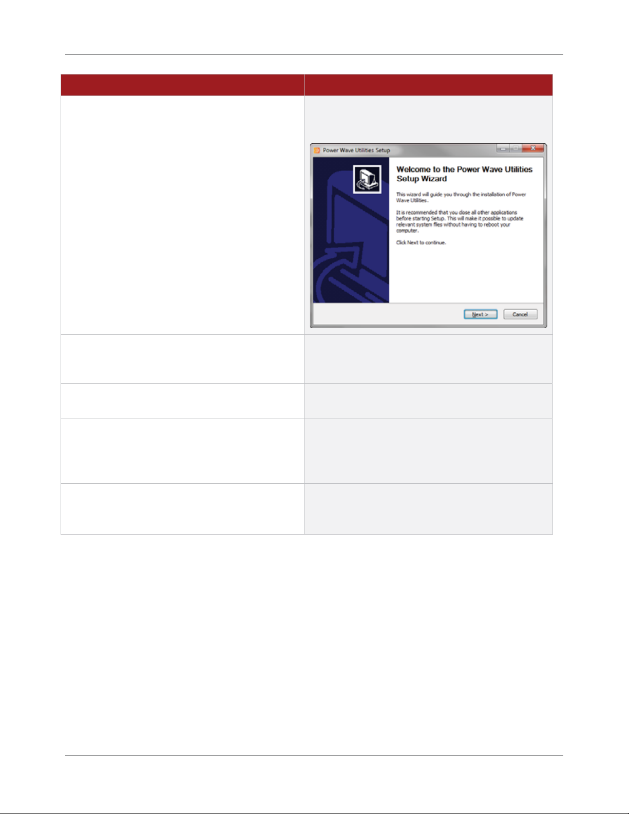
If this is a new inst a llation (or once the old version
is removed), t he system displays the installation
welcome windo w.
7. Click Next on the Welcomescreen to move to
the License Agreement and continue the
installation.
8. You must accept the License Agreement and
click Next to continue.
9. Leave the default value in the Destination
Folder field and click Install.
10. Click the Finish button to exit the installer.
The syste m extracts files and in stalls the Power
Wave® Utilities o n yo ur c o mputer. Once it is
complete, the final page of the Setup Wizard
opens.
Congratulations! You have installed Power Wave®
Manager and can now configure your Welding
Power Source.
Enable CheckPoint™ for a Power Source
Now that you have upgraded the firmwa re on the Welding P ow er Source and installed the latest version of
Power Wave® Manager on your computer, you can now use Power Wave® Manager to enable CheckPoint™
on the Welding Power Source.
Establish Connection to the Welding Power Source
When you updated the firmware on the Welding Power Source (page 2.1), you needed to tell the Update
Utility whe r e to find the Welding Power Source on your network. Now you need to tell P owe r Wave®
Manager where to find the Welding Power Source on your network so you can enable CheckPoint ™ for t hat
power source.
2.6 CheckPoint™User Manual IM8000
Page 29

Enable CheckPoint™ for a Power Source Chapter 2. Preparing for CheckPoint™
Figure 2.1 Connecting to the Welding Power Source
NOTE | Remember that the IP address displayed is either the last
Welding Pow er Source to which Pow er Wave® Manager
connected o r t hat you recently upda t e d w ith the Update
Utility.
Procedure Details
1. Select Start > Programs > Lincoln Electric >
Power Wave® Utilities from the computer’s
main program menu.
2. Select Power Wave® Manager to launch
the utility.
3. Choose the Connect through E thernet option
and enter the IP address of the Welding
Power Source.
4. Click the Connect button.
The Power Wave® Manager window opens and
defaults to the Connect screen. See Figure 2.1.
For more details or information on finding t he IP
address of the Welding Powe r Sour ce, ple a se refer
to the Power Wave® Manager User Manual.
The system establishes the connection and
automatically displays the Registration page of
Power Wave® Manager so you can enable
CheckPoint™ (Figure 2.2 on page 2.8). Please
continue to Enabling CheckPoint™ on page 2.8.
IM8000 CheckPoint™ User Manual 2.7
Page 30
Chapter 2. Preparing for CheckPoint™ Enable CheckPoint™ for a Power Source
Enabling CheckPoint™
Once you connect the Welding Power Source to Powe r Wave® Manage r, you can now enable and set up
CheckPoint™ for that power source. Once you enable Chec kPoint ™ for the power source, the CheckPoint™
administrato r w ill be able to begin adding Welding Power Sources to the C hec kPoint™ system for
monitoring and reporting.
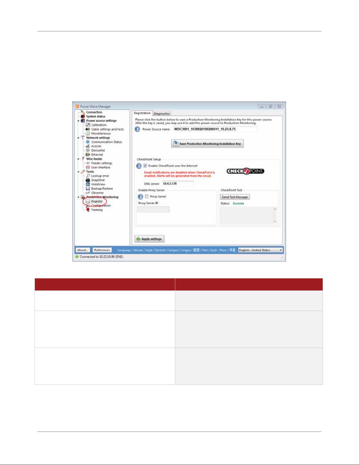
Figure 2.2 Registration Section of P ower Wave® Manager
Procedure Details
1. Select Register under Production Monitoring
in Power Wave® Manager.
2. Enter a name for the Welding Power Source
in the Power Source name field.
3. Place a check mark in the Enable
CheckPoint™ over the Internet checkbox
under CheckPo int™ Set u p .
If you do not see this section, the firmware on the
connected Welding Power S ource is not up to date.
Please refer to page 2.1 to update the firmware of
the power source. Return here when complete.
Once you enable CheckPoint™ for the power source,
the Welding Power Source no longer sends e-mail
notifications. With Chec kPoint ™, e-ma il a nd text
message notifications come from the data center.
2.8 CheckPoint™ User Manual IM8000
Page 31

Enable CheckPoint™ for a Power Source Chapter 2. Preparing for CheckPoint™
Procedure Details
4. Enter an IP address in the DNS server field.
5. If you are using a proxy server, place a check
mark in the Proxy Server checkbox under
Enable Proxy Server and enter the IP address
of that server in the Proxy Server IP field.
6. Once you have entered all require d
information, clic k t h e Apply s e t tings button.
7. Accept the End User Agreement to continue.
This information is not mandator y. If you are unable
to obtain it, you can still continue.
If you are using a proxy server, continue with step 5.
If you are not using a proxy server, skip to step 6.
If you are not using a Proxy Server, you can leave
these options blank and continue with step 6.
You can obtain the proxy information from the
Network Adm inist r ator. This information is necessa r y
in order to gain access to the Internet from your
network through the proxy server.
The syste m d isp lays the End User License Agreement.
STOP | Power Wave® Manager resets the Welding
Power Source when you click the Apply settings
button. Be careful that the power source is not
currently welding.
Once you have applied your settings, you need to test
those settings and make sure the connection to the
data center is successful.
8. Click the Send Test Message button.
If the settings were correct, you should rec eive the
Status: Success message displayed under the butto n
(Figure 2.2).
TIP | If you received a Status: Failed message, you
can hover your m ouse over the message to see why
your test fa iled. Please refer to Appendix A for
more details.
One final ste p rem a ins and that is to save an
installation key file for the Welding Power S ourc e
that you will upload to Chec kPoint ™ in o r de r to
create your company’s account. See page 2.10 for
more information.
IM8000 CheckPoint™ User Manual 2.9
Page 32

Chapter 2. Preparing for CheckPoint™ Enable CheckPoint™ for a Power Source
Save the Production Monitoring Installation Key File
Each individual power sour c e has a unique installa tion key file. The system uses these files to register the
equipment in CheckPoint™. The steps be low walk you thr ough how to save the installa t ion ke y file for the
Welding Power Sour c e . Each Welding Power Source you add to CheckPoint™ needs its own key file .
Figure 2.3 Save an Installation Key File
On the Registration tab of Power Wave ® Manager (F igur e 2.3), simply click the Save Production Monitoring
Installat ion Key button and save the file on your computer or network. Close Power Wave® Manager when
finished
STOP | It is recommended that y ou do not change the text in t he
Power Source name field, especia lly after creating files f rom
the power so urc e ( e.g., training files or ba c kups). Power
Wave® Manag er us es t he Power Source name to organize
and name weld training, backups, S na pShot files, weld log s ,
calibration logs, and more. If you cha ng e a name, you will
have to find and load files manually .
2.10 CheckPoint™ User Manual IM8000
Page 33

Chapter 3
Setting up CheckPoint™
Now that you have updated the Welding Power Source fir mware , have the latest version of Power Wave®
Manager software installe d, a nd ha ve e na bled Che c kPoint ™ for the fir st Welding P ow e r Source , you are
ready to create the Administrator user account in CheckPoint™ and register your company in the data
center.
Connecting to CheckPoint™
When you want to connect to CheckPoint™—which you can do anytime, anywhere—you simply visit the
following web site: www.lincolncheckpoint.com (Figure 3.1). From this page, you can log in to
CheckPoint™ (once you have a user account), take a tour of all the features of CheckPoint™ and lear n all
about using CheckPoint™ on the move.
Figure 3.1 CheckPoint™ Welcome Page
To set up your company’s account for the first time, you need to navigate to that web address now. When
you click Get Started, the Get Started page (Figure 3.2) acts as a basic checklist to make sure you have
completed all the nece ssary prepa rat ion be fore you c ontinue.
IM8000 CheckPoint™User Manual 3.1
Page 34

Chapter 3. Setting up CheckPoint™ Create Administrator Account
Figure 3.2 Get Started Page
Create Administrator Account
When you create your company’s account in CheckPoint™, the very first step is to create the administrator
user account. Once you create your user account, you can add your first Welding Power Source a nd
register your company.
Figure 3.3 New Account Page
3.2 CheckPoint™ User Manual IM8000
Page 35

Validate User Information in CheckPoint™ Chapter 3. Setting up CheckPoint™
Procedure Details
1. Click Get Started on the Home page.
2. Read through each step on the page and
click the link in the final step to begin.
3. Complete the info r m atio n o n the New
Account page and click Submit.
See Figure 3.1 on page 3.1. The Getting Started page
opens (Figure 3.2).
The New Account page opens (Figur e 3.3). This is
where you w ill create the administra tor user account.
NOTE | The first user creat ed is the CheckPoint™
administ ra tor account. This user ha s a c c e ss t o se t up
other users a nd add Welding Power Sources in
CheckPoint™.
After you submit the informat ion, t he system sends a
verification e-mail to the e-mail address you entered.
Validate User Information in CheckPoint™
Validating your user informat ion is simple and ge t s you closer to using CheckP oint ™ to monitor your
welding opera tions. Check your e-mail inbox for a message fro m CheckPoint™. Open the e-mail and click
the validatio n link c o nta ine d w it h in it (Figur e 3.4).
Figure 3.4 Validation E-mail
TIP | If you do not see an e-mail f rom C hec k Point™, check your
Junk Mail f older.
Once you click t he va lida tion link, the administrator account is now a ctive an d you ca n add the fir st Welding
Power Source and register your compa ny in the data center.
IM8000 CheckPoint™ User Manual 3.3
Page 36

Chapter 3. Setting up CheckPoint™ Uploading the Installation Key File
Uploading the Installation Key File
Once you validate the administra t o r user account, you nee d to registe r your first Welding Power Source.
You register a pow er sour ce by uploading the installation key file yo u sa ve d o n page 2.10. Only t he n will
you be able to finish registering your c o mpa ny and begin a dding more users and powe r sources to
CheckPoint™.
NOTE | You must register at lea s t one Welding Power Sourc e t o
create a valid c ompany account. You will not be able to
continue without the installation key file. See page 2.10 for
details on saving the key file.
After you click the va lidation link in the e-mail, the system o pens a page detailing instr uc tions on how to
save the Welding Power Source installatio n key file fo r those without access to this ma nual. You can click
Continue on that page.
Figure 3.5 Uploading the Installation Key File
To create the first W e lding P o w er S o urce ent ry in C he ckPoint™ and uploa d the inst allation key file:
Procedure Details
1. Click the Continue button at the bottom of
the Registration Step 1 page.
2. Enter the name of the power source in the
Welder Name field.
3. Enter informat ion about the Welding Power
Source in the Welder Description field.
4. Next to the Installation File field, click the
Select button
3.4 CheckPoint™ User Manual IM8000
The CheckPoint™ Registration Step 2 page opens
(Figure 3.5).
The text you enter here appears as the name of
the welder in the Asset Tree for all users (Figure
4.21 on page 4.22). Be sure you can distinguish
multiple Welding P ower Sources from one
another.
Generally, you want to use the Welder Description
field to display the model of the power source.
See Figure 3.5.
Page 37

Register Your Company Chapter 3. Setting up CheckPoint™
Procedure Details
5. Navigate to the location where you saved the
installation k e y file and click Open.
6. Click the Continue button.
The Registration Step 3 page displays. It is now
time to register your company.
Register Your Company
Once you create an administrator acc ount and add your fir st Welding Powe r Source t o CheckP oint ™, you
need to register your company in the data center . See page 3.7 for details on multiple C ompany S it es.
Figure 3.6 Register Your Company
To register your company:
Procedure Details
1. On the Registration Step 3 page, enter you r
company’s information.
2. Click the Continue button.
IM8000 CheckPoint™ User Manual 3.5
The system displays the final step of the registration
process.
Page 38

Chapter 3. Setting up CheckPoint™ Register Your Company
Procedure Details
The Set ting up your system page displays once you
submit your company’s information.
NOTE | This process takes a little time so do not
click the Back or Refresh buttons dur ing t he process
or it may fail.
Once the account is registered, the Process
Completed page displays.
3. Click the link in the message to lo g in to
CheckPoint™ for the first time as the
administrator user.
The syste m d isp lays the End User License Agreement
page.
3.6 CheckPoint™ User Manual IM8000
Page 39

Creating Multiple Sites Chapter 3. Setting up CheckPoint™
Procedure Details
4. Place a check mark in the I agr e e with the
above terms and conditions checkbox and
click Continue.
5. Complete the information on this screen and
click the Save button.
A page opens requesting you to change your
password, as well as enter additional information for
the user account, including a secur it y question in the
event you forget your password.
Once yo u sa ve your security information, the system
opens CheckPoint™ for you. Chapter 4 explains how
to manage CheckPoint™, and Cha pter 5begins to
explain how to use CheckPoint™.
Creating Multiple Sites
Please contact Lincoln Elec tric CheckPoint™ support to register multiple C ompany Sites. In the USA or
Canada, dial 1.800.691.5797. The dire ct dia l number is 1.727.786.012 1. You c a n also e-mail support a t :
support@lincolnelectricproductionmonitoring.com
.
IM8000 CheckPoint™User Manual 3.7
Page 40

Chapter 3. Setting up CheckPoint™ Creating Multiple Sites
THIS PAGE INTENTIONALLY LEFT BLANK.
3.8 CheckPoint™ User Manual IM8000
Page 41

Chapter 4
Managing CheckPoint™
The CheckPoint™ Manager allows you to manage user acc ount s, shift sche dule s, w e lde r s, alert hist ory and
documents in CheckPoint™. The settings in the CheckPoint™ Manager affect all users.
NOTE | To access the CheckPoint ™ M a na g er, y our user account
must have the Administrator access associated with it.
To access the CheckPoint™ Manager, simply click the dr op-down arrow under your user name at the top of
page and click Manage (Figure 4.7).
Figure 4.7 Access Management Area
NOTE | If you have more than one s ite , first use the drop-down l ist
to select the loc a tion you want to manage then c lick the
Manage link.
Tabs in the CheckPoint™ Manager
In the CheckPoint™ Manager, the tabs across the top of the page provide access to the various settings
available (Figure 4.8). You must have Administrator access associated with your user account in order to
access and edit this information.
The General tab displays the details on the Company Site and is the information entered when
the company’s account was created.
The User Manag e ment t a b a llow s you t o add, dele te and modify user access.
The Shift S c hedule tab allows you, add, edit and manage shifts.
The Welders t a b a llow s you t o add, delet e and move Welding Power Sourc e s.
The Alert History tab allows you to view the status of alerts sent.
The Documents t a b a llow s you t o add up to 15 GB of documentation, providing a single point of
data storage for engineering, QA and maintenance doc umentation.
IM8000 CheckPoint™User Manual 4.1
Page 42

Chapter 4. Managing CheckPoint™ Filtering Lists in the CheckPoint™ Manager
Figure 4.8 CheckPoint™ Manager
Filtering Lists in the CheckPoint™ Manager
You can use the filters at the top of each column to narrow the alert list to only those you want to see.
Simply enter the text you want to search, click the Filter icon ( ) and select the relatio n ship t h a t te xt has
with the entry(ies) you want to see.
Figure 4.9 Filtering a List
For example, on the User Management tab, if you only want to see a list of the users with the last name
of “Smith”, you can type smith in the Last Name filter and click th e Filter icon ( ). Select Equal To from
the drop-down. The system automatically refreshes the list and displays only those users whose last
name is Smith.
4.2 CheckPoint™ User Manual IM8000
Page 43

General Tab Chapter 4. Managing CheckPoint™
General Tab
When your company is first created in the system, the CheckPoint™ administrator entered your company’s
name and address, along with the Site Name. You can edit this information if ne c e ssar y (perha ps you have
moved to another address). In addition to your Company Site’s details, you ca n spec ify the devices allowed
to contribute informat ion to Chec kPoint ™. This is useful if you purcha se a welding pow e r source fr om
another company who also uses CheckPoint™.
Figure 4.10 Com pany and Site Inform ation
Company Info rmation
When you need to edit the details of your company’s information (e.g., site na me or address), you can
simply edit the fields in the Company Information section of the General tab. If your company has multiple
locations (or sites), you can edit the informat ion for each site. In the drop-down in Figure 4.7 on page 4.1,
select the Company Site and click Manage to edit any of the site’s configuration options. All of the tabs
(e.g., General, User Ma na g ement, Shift Schedul e) relate to the site you have selected in the drop-down.
Allowable IP Addresses
To help prevent cross contamination of data when you move a Welding Power Source to another Container
or sell it to another company, Chec kPoint ™ keep s a list of allowa ble source IP addresses for the power
source. When the CheckPoint™ data center receives data, it rec or ds the source IP address and associates it
with the transaction. If the source IP address is not valid, Che c kP oint ™ disc a r ds the transa ction.
To add an allowable IP address, simply click the New IP Address button on the General tab, enter the IP
address and click Save.
IM8000 CheckPoint™ User Manual 4.3
Page 44

Chapter 4. Managing CheckPoint™ User Management
User Management
The User Manag e ment tab allows admini strator users to set up users and gra n t access t o the system.
When you first set up the system, only the individual that set up the company account is the administrator
in CheckPoint™ at that time. That user has t he a b ilit y to add users and give administrator access t o other
individuals.
TIP | If you have yet to add all of your Welding Power Sources or
create your S hift Schedules, you should skip to page 4.17
before creat ing your users. The system se nds those users
an e-mail to complete their registration. If you aren’t ready
for users to vi ew any reports, return t o t his section later.
Display Curren t Users
When you click the Users tab, the sy stem displays a list of cur rent users with some basic information a b o u t
the account such as the user’s last name and first name; the e-mail address associate d w ith the account;
and if the account status is Active or Locke d. The list also display s t he user ’s Ho me Sit e (i.e., the company
under which their user acc ount was initia lly c r e a te d).
Figure 4.11 List of Us ers
4.4 CheckPoint™ User Manual IM8000
Page 45

User Management Chapter 4. Managing CheckPoint™
Add a User Account
Now that you have your system all set up and ready to go, you’re ready to provide your team with access to
CheckPoint™. In order to do this, you need to create a user account for each person.
NOTE | Once you save the user account, CheckPoint™ automatically
sends the use r a n e- ma il to validate their ac c ount. Be sure
you are ready f or people to begin logging in and using
CheckPoint™.
Figure 4.12 New Us er Ac count
To create a new user:
Procedure Details
1. On the User Management tab in the
CheckPoint™ Manager , click t he New
User button.
2. Enter all user inform a tion in the
Information se ction.
IM8000 CheckPoint™ User Manual 4.5
The New page opens (Figure 4.12).
The user’s e-ma il a ddr ess will become their user
name to log in to CheckPoint ™.
Page 46

Chapter 4. Managing CheckPoint™ User Management
Procedure Details
3. From the drop-downs in the Site Admin
Options section, sele ct Yes for only one of
the perm issio ns.
4. Click the Save button.
Administrator: Sele c t Yes to allow the user to
access the CheckPoint ™ Manage r to add, e dit, and
delete user accounts, Shift Schedules, Welding
Power Sources and documents. This also includes
the ability t o acce ss and modify their personal
account settings.
OR
Management: Select Yes to allow the user to
access their personal profile and modify t heir own
account settings but prevent the m from accessing
the CheckPoint™ Manager.
Once you click Save, the system send s an e-mail to
the user at the e-mail address you entered. Be
sure to instr u c t t hem to click the link in that e-mail
to complete their registration with CheckPoint™.
Edit a User Account
There are a variety of reasons to edit a user’s acco unt , inc luding he lping t he m out if the y have trouble
editing information in t he ir pr ofile . From the Che c kP oint ™ Mana ge r , the administr a t or user ha s a cce ss to
modify each section of a user’s profile, includi ng a ddit ional infor ma t ion a bout the ir site permissions and
advanced programming settings.
Figure 4.13 Editing a User Account
To edit a user account, simply click the Edit link next to the user account and make your changes (Figure
4.11 on page 4.4). Remember to click the Save button to commit your changes. If you want to exit without
committing any changes, click the Cancel button.
4.6 CheckPoint™ User Manual IM8000
Page 47

User Management Chapter 4. Managing CheckPoint™
Personal Inf ormation
Please see page 5.3 for more in-depth information.
Password Cha nge
Please see page 5.4 for more in-depth information.
Display Prefer ences
Please see page 5.4 for more in-depth information.
Daily Digest
Please see page 5.5 for more in-depth information.
Alert Subscriptions
Please see page 5.6 for more in-depth information.
Site Membership
If your company has multiple Co mpany Sites (or locations), each CheckPoint™ user can have access to
any combination of those sites. Under Site Membersh ip, a CheckPoint™ administrator can view the
sites currently associated with the user’s account and remove any that are no longer applica ble.
Simply click th e Delete link next to the site.
NOTE | You can only make changes t o t he user under their Hom e
site. Select that site from the drop-down under your name
and click Manage (Figure 4.7 on page 4.1).
Advanced Settings
For those users who have third-party applications tha t need t o communic ate w ith the database or
have a need to pull information from the databa se, the Advanced settings allow you generate a unique
access key for that user. This code allows the user to access the infor mation in the database
programmatically. Simply click the Add New Key button to generate a new Application Programming
Interface (API) k e y fo r th is use r .
For more information or for assistance, plea se contact Lincoln Ele ctric CheckPoint™ support. In the
USA or Canada, dial 1.800.691.5797. The direct dial number is 1.727.786.0121. You can also e-mail
support at: support@lincolnelectricproductionmonitoring.com
.
Delete a User Account
There are many reasons why you may need to remove a user account from CheckPoint™. If the employee
leaves the company or the account was entered by mistake, you can easily keep your system up to date.
To delete a user, simply click the Delete link next to the user account. The system displays a confirmation
message to make sure you want to remove the user account. This helps prevent accidental dele t ion. Click
OK if you want to delete the account.
IM8000 CheckPoint™ User Manual 4.7
Page 48

Chapter 4. Managing CheckPoint™ Shift Schedules
Shift Schedules
To help you view the data from the Welding Power Sources in your company, Chec kPoint™ provides you
with the abilit y to create a Shift Sche dule in the application that matches your real production Shift
Schedule. When you generate reports, you often ha ve the option to display w e lding da t a for a specific
shift—sometimes all the way down to the hour within the shift.
When you click the Shift Schedule tab (Figure 4.14), the system displays the list of shifts currently active in
CheckPoint™. The list displays some basic information about the shift such as the start and end time, and
how often the shift repeats.
Figure 4.14 Shift Schedul e T a b
TIP | You can see more in-depth ex amples on the flexibilit y of
shifts in CheckPoint™ starting on page 4.13.
Next Production Day
The concept of “Next Production Day” in CheckPoint™ relates to a shift that crosses the midnight threshold
of a calendar day and the data generated during that time period. For the welds that were performed
during this type of shift, the system needs to know how you want to include that data on reports in relation
to dates. When you set up the shift schedule, there is a chec kbox calle d Next Production Day that appears
when the time in the Company Time field crosses that midnight threshold. This chec kbox contr ols how t he
weld data appears on the reports.
For example, the first shift of the “production” day at United Engineering actually begins at 11:00 PM the
previous calendar day. Any welds that were performed dur ing t he part of the shift before midnight on
February 1 need to be included with the data collec t e d aft e r midnight on Fe br uary 2 (i.e ., the next
production day). With a check mark in the Events occurring during this shift should be assigned to the next
production day checkbox on that first shift, if any users generate a report for February 2, those welds
performed from 11:00 P M to midnight on F ebrua r y 1 w ill a lso be inc lude d.
Alternatively, the t hird shift of t he “production” da y at Adva nced Ma nufa cturing a ctua lly ends at 7:00 AM
the next calendar day. Any welds that were performed during the part of the shift afte r midnight on
February 2 need to be included with the data collected before midnight on February 1 (i.e., the same
production day). With NO check mark in the Events occurring during this shift should be assigned to the
next production day checkbox on that third shift, if any users generate a report for February 1, those welds
performed from midnight t o 7:00 AM on February 2 will also be included.
4.8 CheckPoint™ User Manual IM8000
Page 49

Shift Schedules Chapter 4. Managing CheckPoint™
Add a Shift
Adding a shift to CheckPoint™ is simple. Simply click t h e N ew Shift button at the top of the Shift Schedule
tab (Figure 4.14 on page 4.8). The system displays t he New Shift window. Based on your needs for this
shift entry, c o mp le te the information on the scree n and c lic k Save. Table 4.1 explains the fie lds in det ail.
Figure 4.15 Shift D e t a ils Screen
Table 4.1 Fields on the Shif t Det a ils S c reen
Field Description
General Section
Shift Name Depending on your needs, you can enter a new name for the shift or you can
select an existing name from the drop down list. If you select an existing shift
name, the system associates the data collected during this newly entered shift,
in addition to other shifts with the same name, in the report as a single shift. In
Criteria windows, the Shift drop-down will also display a single entry for all
shifts with the same name.
Description Enter a brief desc r ipt io n of the shift . If yo u have m ultiple configurations for the
same shift, you need the Description field to help you tell t hem a par t in the list
of shifts (Figure 4.14 on page 4.8).
IM8000 CheckPoint™ User Manual 4.9
Page 50

Chapter 4. Managing CheckPoint™ Shift Schedules
Field Description
User Time and
Company Time
Events occurring
during this shift
should be assigned
to the next
production day
Start Date
Set the start and end time of the shift in the User Time fields. Click the clock
icon ( ) to display a pop-up time selector. You can also simply type the time.
The User Time fields are set to your time zone (i.e., the user currently viewing
the screen). CheckPoint™ automatically converts the time to the time zone of
the Company Site you are currently mana ging and displays it in t h e Company
Time fields.
For example, Mark at Worldwide Indust r ia l is in C a lifor nia . H is t ime zone is
Pacific (GMT -8:00). He has seve ral C o mpa ny Sites he monito rs using
CheckPoint™. Ohio (GMT -5:00) is one of them. He wants to add a Shift to this
Company Site for 6:00 AM to 2:00 PM (Ohio time). In the User Time fields, he
clicks the clo c k ic o n ( ) next to From and selects 3:00 AM from the menu.
Then he clicks t h e c lock icon ( ) next to the To field and selects 11:00 AM
from the menu. CheckPoint™ aut omat ica lly display s 6:00 AM to 2:00 P M next
to Company Time.
If the midnight threshold of the Company Time occurs between the time
entered in the From field and the time in the To field, CheckPoint™ displays a
checkbox so you can verify the production day for the data collecte d during this
shift. See page 4.8 for mor e details on Next Production Day.
Start Date The Start Date section allows you to set the date the shift becomes effective.
There are two options:
The No Starting Date option uses the date January 1, 2000, as the
base day.
The Effective Date option allows the user to select a day the shift
begins. You can type the date manually or click the calendar icon ( )
for an interactive ca le ndar. This is useful wh e n you ne ed to create
complex schedules wher e shifts be gin on a spec ific da y of the wee k .
4.10 CheckPoint™User Manual IM8000
Page 51

Shift Schedules Chapter 4. Managing CheckPoint™
Field Description
End Date
End Date
The End Date section allows you to deter mine when the shift stops. There are
three options.
If there is no end date for the shift, choose The shift continues fore ver.
If the shift only occurs a certain number of times, choose the second
option and specify how many times you want the shift to occur.
The last option allows you to select a cer t ain date on which the shift
ends. You can manually type the date or use the interactive calendar.
To use the cale ndar, click on the calendar icon ( ).
Repeat Settings
Repeat Frequency The Repeat Frequency field allows you to determine how often this shift
configuration repeats. The sett ings ava ila ble depend on the freque nc y you
select.
Repeat Frequency:
None
When you select None from the drop-down, the shift is set up to never repeat.
The shift occurs only once on the effective date and then becomes inactive.
Repeat Frequency:
Hourly
The system disables the No start ing date option in the Start Date section and
disables the whole End Date section. For example, an extra shift might have
occurred only once on 03/28/2012.
When you set a shift to repeat Hourly, you can configure how many hours make
up that “hourly” interval. To change the number of hours, either manually type
a number into the text field or use the up and down arrows to increase or
decrease the value.
IM8000 CheckPoint™User Manual 4.11
Page 52

Chapter 4. Managing CheckPoint™ Shift Schedules
Field Description
Repeat Frequency:
Daily
Repeat Frequency:
Weekly
When you set a shift to repeat on a Daily basis, you can configure the day
interval. For example, the shift might occ ur every other day so you could set
the interval to Every 2 days. Alternatively, you can set the shift to occur every
weekday (i.e., Monday, Tuesday, Wedne sda y, Thur sday a nd F r ida y).
When you set a shift to repeat on a Weekly basis, you can configure the week
interval of the shift, including the days of the week on which the shift should
occur. For example, the shift might occur every fifth week on Monday,
Wednesday, and Friday, so you would enter 5 in the text field and pla ce a check
mark above Mon, Wed and Fri.
To change the number of weeks, either manually type a number int o the text
field or use the up and down arrows to increase or decrease the value . To
indicate on which day(s) of the wee k the shift oc c ur s, plac e a chec k mar k in the
appropriate day’s checkbox.
Repeat Frequency:
Monthly
When you set a shift to repeat on a Monthly basis, you can configure the shift
using two different options:
Specific Day: The shift can occu r o n a specific day of the month. For
example, the shift might occur every first day of the month.
General Day: The second option is to set the shift to occu r on a general
day of the month. For example, the shift might occ ur every last Friday
of the month.
For both options, you can also set the month interval of the shift. For example,
the shift might occur on the first day of the month every six months.
4.12 CheckPoint™User Manual IM8000
Page 53

Shift Schedules Chapter 4. Managing CheckPoint™
Field Description
Repeat Frequency:
Yearly
When you set a shift to repeat on a Yearly basis, you can configure the shift
using two different options.
Specific Date: You can set the shift to oc c ur on a spec ific da y o f a
specific month. For example, the shift might occur on the July 17
every year.
General Day: The second option is to set the shift to occur on a general
day of a specific month. For example, the shift might oc c ur on the last
Friday of June every year.
Edit a Shift
If you want to edit the details of a shift, simply click the Edit link next to the shift on the Shift Schedule tab.
Table 4.1 on page 4.9 explains the fields of the Shift Deta ils pa ge in more depth.
Remove a Shift
If you want to remove a shift from the system, you can simply click the Delete link next to the shift on the
Shift Sched ule tab.
STOP | Once you remove a shift, the data collected and associated
with that shif t w ill no longer be available.
Shift Sch edule Example – Three Basic Shi f t s
Advanced Manufacturing has a daily Shift Schedule with three shifts. Their Production Day begins with the
morning shift, and their shift times are:
Morning Shift: 6:00 AM to 2:00 PM
Day Shift: 2:00 PM to 10:00 PM
Night Shift: 10:00 PM to 6:00 AM
IM8000 CheckPoint™ User Manual 4.13
Page 54

Chapter 4. Managing CheckPoint™ Shift Schedules
Figure 4.16 Shift Schedul e Ex ample – Three Basic Shifts
Setting up the Morning Shift
First, John (the CheckPoint™ administrator user) sets up the Morning Shift. (If a default shift already
exists, you can edit the default shift or creat e a new one. See page 4.9 for details.) John clicked New
Shift and entered the following informat ion in t he indicated fields to complete the details on the new
shift:
Shift Name: Morning Shift
Description: Morning Shift
Company Time: From 6:00 AM to 2:00 PM
Start Date: The shift has no starting date. The pattern is the same every day, every week.
End Date: The shift continues forever.
Repeat Frequency: Daily, Every 1 day
Once he completed this configura tion, he clicked the Save button.
Setting up the D ay S hift
Next, John needs to set up the Day Shift. John c lic ke d Ne w Shift and entered the following information
in the indicated fields to complete the details on the new shift:
Shift Name: Day Shift
Description: Day Shift
Company Time: From 2:00 PM to 10:00 PM
Start Date: The shift has no starting date. The pattern is the same every day.
End Date: The shift continues forever.
Repeat Frequency: Daily, Every 1 day. The pattern starts over every day.
Once he completed this configura tion, he clicked the Save button.
4.14 CheckPoint™ User Manual IM8000
Page 55

Shift Schedules Chapter 4. Managing CheckPoint™
Setting up the N ight Shift
Finally, John sets up the Nig ht S hift. John clicked New Shift and entered the following information in
the indicated fields to complete the details on the new shift:
Shift Name: Night Shift
Description: Night Shift
Company Time: From 10:00 PM to 6:00 AM
Next production day: Since this shift is part of the curre nt production day, John lea ve s t he
Events occurring during this shift should be assigned to the next production day checkbox empty.
See page 4.8 for more details on Next Production Day.
Start Date: The shift has no starting date.
End Date: The shift continues forever.
Repeat Frequency: Daily, Every 1 day
Once he completed this configura tion, he clicked the Save button.
Shift Schedule Exampl e – Two Alternat ing Shift s, No Weekends
United Engineering has two shifts that alternate between day shift and night shift every other week. In
addition, no one works on the weekends. They have named their shifts: Shift A and Shift B.
Shift A starts at 6:00 AM and ends at 6:00 PM the first week and starts at 6:00 PM and ends at
6:00 AM the next week.
Shift B start s at 6:00 P M and ends at 6:00 AM the first week and starts at 6:00 AM and ends at
6:00 PM the next week.
This requires Tom (the CheckP oint ™ a dminist r a t o r user) t o creat e two diffe r e nt shift c onfigur a t ions for e ach
shift in CheckPo int ™.
Figure 4.17 Shift Schedul e Example – Two Alt ernating Shifts, No Weekends
IM8000 CheckPoint™ User Manual 4.15
Page 56

Chapter 4. Managing CheckPoint™ Shift Schedules
Setting up Shift A – First Week
First, Tom needs to set up the first configuration for Shift A. (If a default shift already exist s, you c a n
edit the default shift or create a new one. See page 4.9 for details.) Tom clicked New Shift and
entered the following information in the indicated fields to complete the details on the new shift:
Shift Name: Shift A
Description: Shift A – First Week
Company Time: From 6:00 AM to 6:00 PM
Start Date: 4/2/2012
End Date: The shift continues forever.
Repeat Frequency: Weekly, Every 2 weeks on Mon, Tue, Wed, Thu and Fri
Once he completed this configura tion, he clicked the Save button.
Setting up Shift B – First Week
Next, Tom needs to set up the first configuration for S hift B. Tom clicked New Shift and entered the
following inform ation in the indicated fields to c o mp le te the details on the new shift:
Shift Name: Shift B
Description: Shift B – First Week
Company Time: From 6:00 PM to 6:00 AM
Next production day: Since this shift is part of the curre nt production da y, Tom le a ve s the
Events occurring during this shift should be assigned to the next production day checkbox empty.
See page 4.8 for more details on Next Production Day.
Start Date: 4/2/2012
End Date: The shift continues forever.
Repeat Frequency: Weekly, Every 2 weeks on Mon, Tue, Wed, Thu and Fri
Once he completed this configura tion, he clicked the Save button.
Setting up Shift A – Alternate Week
Next, Tom is ready to set up the second configuration for Shift A. Tom clicked New Shift and entered
the following infor m a tion in the indicated fields to comple te the details on the new shift:
Shift Name: Shift A
Description: Shift A – Alternate Wee k
Company Time: From 6:00 PM to 6:00 AM
Next production day: Since this shift is part of the curre nt production da y, Tom le a ve s the
Events occurring during this shift should be assigned to the next production day checkbox empty.
See page 4.8 for details on Next Production Day.
Start Date: 4/9/2012. Since Tom wants to create an alternating wee kly sche dule , he nee ds to
give CheckPoint™ a starting point for the alternate week of Shift A that works in tandem with
the start date on the first week of Shift A. Since the Alternate Week configuration is a week
4.16 CheckPoint™ User Manual IM8000
Page 57

Welding Power Sources Chapter 4. Managing CheckPoint™
after the First Week, he enters a date that is seven days after the start date he entered on the
First Week.
End Date: The shift continues forever.
Repeat Frequency: Weekly, Every 2 weeks on Mon, Tue, Wed, Thu and Fri
Once he completed this configura tion, he clicked the Save button.
Setting up Shift B – Alternate Week
Finally, Tom needs to set up the second configura t ion for Shift B. Tom clicked New Shift and entered
the following infor m a tion in the indicated fields to comple te the details on the new shift:
Shift Name: Shift B
Description: Shift B – Alternate Week
Company Time: From 6:00 AM to 6:00 PM
Start Date: 4/9/2012. Since Tom wants to create an alternating week ly sche dule , he nee ds to
give CheckPoint™ a starting point for the alternate week of Shift B that works in tandem with
the start date on the first week of Shift B. Since the Alternate Week configur a t ion is a week
after the First Week, he enters a date that is seven days after the start date he entered on the
First Week.
End Date: The shift continues forever.
Repeat Frequency: Weekly, Every 2 weeks on Mon, Tue, Wed, Thu and Fri
Once he completed this configura tion, he clicked the Save button.
Welding Power Sources
The Welders t a b a llow s a dminist r a t o rs t o define t heir Company Site, as well as create and manage the
Welding Power Source entries and Containers of power source entries that appear in the Asset Tree for all
users in the main CheckPoint™ applica t ion. When you first se t up the system, you wa nt to be sure how you
want to organize your Asset Tree before you start.
NOTE | If you are using Overall Equipment Efficienc y (OEE) to
monitor and improve the effective ness of your
manufacturing processes, this sec tion of CheckPoint™
Management also allows you to ident ify your Planned
Downtime per Container and per Welding Power Source.
IM8000 CheckPoint™ User Manual 4.17
Page 58

Chapter 4. Managing CheckPoint™ Welding Power Sources
Figure 4.18 Welders Tab
When you click the Welders tab, the system display s the Company Site(s) and the Welding P ow er S ources
and Containers of power sources currently added in your system, along with their properties. This list
includes ALL Welding Power Sources and Containers currently in your system, including any that are
currently hidden fr om view in t he main Che c kPoint™ a pplic ation.
NOTE | Only users with Administrator access associated with their
user account have the ability to acc e ss and manage
welders.
4.18 CheckPoint™ User Manual IM8000
Page 59

Welding Power Sources Chapter 4. Managing CheckPoint™
Site Configuration and Overall Equipment Efficien cy (OEE)
When you first create your company in CheckPoint™, the first level on the Welders tab is the Company Site.
Configuring your site’s Idle Time Thre s h o ld , Planned Arc Time Per Hour and Planned Downtime allows
CheckPoint™ to calculat e your OEE value s accurat e ly. Table 4.2 e xpla ins the Site Definition section. P l ea se
refer to Chapter 9 for in-depth details on O EE and how to establish your plant ’s Pla nne d Downtime .
Figure 4.19 Configuring Your Company Site
Table 4.2 Fields in the Site Definition Section
Field Description
Name This is the name of the Company Site as it appears in the Asset Tree in the
main CheckPo int ™ applica tion.
Idle Time Thresho ld This is the amo unt o f time that all machine s under this Company Site can
be idle before the lapse in produc t ivit y begins t o be co unted as
Unplanned Downtime. Please see page 9.8 for more details on
Unplanned Downtime.
Planned Arc Time Per Hour Enter the amount of time that you expect every machine under this
Container to be welding. This value is used for OEE calculations. Please
see page 9.8 for more details on the Performance factor of OEE.
IM8000 CheckPoint™ User Manual 4.19
Page 60

Chapter 4. Managing CheckPoint™ Welding Power Sources
Adding a Container
Containers a r e sepa r a te divisions under the main company description in the Asset Tree that allow you to
group Welding P ow er Sources together to suit your needs. You can also define the OEE “idle” and
“planned” times for the Container. Once you create a new Container, you ca n a ssign a new or previously
added Welding Power Source to that Container.
Figure 4.20 Creat i ng a New Container
TIP | To make it easier for you to bui ld your Asset Tree, create all
your Containers first. Then you ca n simply select the
appropriate Container when you create yo ur Welding Power
Source entries (rather than creating them and then editing
them again).
To add a new Container:
Procedure Details
1. Click the New Container button on the
Welders tab.
2. Enter the details of the Container.
The Container Definition window opens (Figure
4.20).
Name: This is the text that displa y s in t h e Asset
Tree for this Container. Typically, this is the name
of an assembly line or work center with multiple
power source s, although it is flexible for any
configuration.
Description: The text here briefly explains to other
users to what entity the Container refers. It
should be understood in a quick glance.
4.20 CheckPoint™ User Manual IM8000
Page 61

Welding Power Sources Chapter 4. Managing CheckPoint™
Procedure Details
Idle Time Thresho ld: This is the amount of time
that all machines unde r this Container can be idle
before the lapse in productivity be gins to be
counted as Unplanned Downtime. Please see page
9.8 for more details on Unplanned Downtime.
Planned Arc Time Per Hour: Enter the amount of
time that you expect every machine under this
Container to be welding. This value is used for
OEE calculations. Please see page 9.8 for more
details on the Performance factor of OEE.
Container: The parent Container is the Container
directly ab o ve this one in the hierarchy of the
Asset Tree.
3. Click the Save button.
The Container appears in the list on the
Welders tab.
Adding a Welding Power Source
Once you have created all of your Container entries, you can begin adding Welding Power Sources to
CheckPoint™. If this is a fresh insta ll, you a lready ha ve a power source a dded to the system. You just need
to add the remaining power sources. Once you create the Welding Power Source entry, you must edit the
entry and specify a Container for the power source if it’s different from the company-level Container (page
4.23) and add any Planned Downtime specific to this Welding Power Source for calculations of OEE (if
applicable).
NOTE | Establishing OEE for your plant requires all information in
CheckPoint ™ t o w ork t og et her. Please see Chapter 9 for
details on OEE and CheckPoint™.
IM8000 CheckPoint™ User Manual 4.21
Page 62

Chapter 4. Managing CheckPoint™ Welding Power Sources
Figure 4.21 Adding a New Welding Power Source
To add a Welding Power S ource to CheckPoint™:
Procedure Details
1. Click the New Welder button on the
Welders tab.
2. Enter the Welder Name and Welder
Description.
3. Click the Select button next to the Installation
File field.
4. Navigate to the installation key file for this
Welding Power Sourc e and click Open.
5. Click the Save button.
The Welder Definition page displays.
Welder Name: The text you enter here appears as
the entry in the Asset Tree (Figure 4.21). Be sure
to use an easily re c o gniza b le na me.
Welder Desc rip tion: The text here briefly explains
to which Welding Powe r Sour ce this entry refers
and is helpful when vie w ing the list of welders in
the CheckPoint™ Manager.
Please refer to page 2.10 for details on saving the
installation key file using Power Wave® Manager.
The Welding Power Source entry appears in the
list of welder s in the CheckPoint™ Manager.
NOTE | Information from the Welding Power
Source may not be a v a ilable for 15 minutes. If it
is not available, be patient. Do not delete it and
attempt to a dd it a g ain. This will cause a lon g er
delay.
4.22 CheckPoint™ User Manual IM8000
Page 63

Welding Power Sources Chapter 4. Managing CheckPoint™
Changing the Container for a Welding Power Source
There may be times when you move Welding Power Sources around on the floor, and you need to reflect
this change in CheckPoint ™. When you first add a power source to CheckPoint™, you might need to place
that power source into a Container. The system mak es it simple to reloca te a welder. On the Welders tab,
simply click the Edit link next to the Welding Power Source you wa nt t o move and select the ne w Container
from the Container drop-down (Figure 4.22). Save your changes.
Figure 4.22 Changi ng t h e C ont a iner for a Welding Power Source
IM8000 CheckPoint™ User Manual 4.23
Page 64

Chapter 4. Managing CheckPoint™ Alert History
Alert History
CheckPoint™ provides several alert messages that users can choose to receive either by e-mail or text
message. They can customize the welders for which they receive alerts. They can also control the amount
of messages they receive. Users can set these options under their User Profile. C heckP oint ™ c a n alert t he
user of the following events:
When a welder powers on
When a welder experiences any System event
When a weld exceeds any limit set in the Weld Profile be ing used for the weld
When a welder experiences a Wire Package Warning event
The Alert History tab here in the CheckPoint™ Manager displays a list of all alert s that the system has sent
to users, along with the date it was sent. To view the details of the alert message, simply hover your mouse
over the corresponding row. For more on alert subscriptions, please see page 5.6.
Figure 4.23 Alert H istory
4.24 CheckPoint™ User Manual IM8000
Page 65

Documents Chapter 4. Managing CheckPoint™
Documents
The Documents t a b is whe r e you can add up to 15 GB of documentation, providing a single library for your
engineering, QA and maintenanc e . You can add documents (or web links) and associat e them to the main
Company Site in the Asset Tree, a s well as to a specific Welding Power Source entry or Container. When
your users click the Documents t a b in the main CheckPoint™ application, the documents display depending
on their selection in the Asset Tree. In the CheckPoint™ Manager, you control what the users see.
Access and Navigate the Library
To access the Document Library, simply click the Documents tab in t he CheckP oint ™ Manager (Figur e 4.24).
You can filter the list based on Container using the drop-down at the top of the list. Click the plus and
minus sign icon ( and ) next to a Container in tha t drop-dow n to expa nd or collapse t he list.
When you select the Container or Welding Power Source from the drop-down, the system displays the list
of docum ents associated with the selected asset (Figure 4. 2 4 ).
Figure 4.24 List of Document s for a Cont ainer
NOTE | You can click the hype rlinked file in the Name column to
view the document or link.
IM8000 CheckPoint™ User Manual 4.25
Page 66

Chapter 4. Managing CheckPoint™ Documents
Add a Document t o the Library
In order to make a document (e.g., PDF, Word document, Excel data sheet) available to other users of
CheckPoint™, you need to upload that document to the data center. In the process, you associate it with a
specific Welding Power Source or Container of power sources, as well as sa ve it in a spe c ific fo lder.
Figure 4.25 Adding a D ocum ent t o the Library
NOTE | Please see page 4.28 if y ou w ould like to add a web link to
the Document Library.
TIP | If you create a backup f ile from your power sources s o y ou
can restore ag ain in the future, the doc ument library is a
great place to sto re tha t f ile. A ssoc iat e t he file with that
individual power source and you’ ll know right where to find
it later.
To add a file to your Document Library:
Procedure Details
1. Click the New Document button.
2. Select Document from the Type drop-down.
The New Document page opens (Figure 4.25).
4.26 CheckPoint™ User Manual IM8000
Page 67

Documents Chapter 4. Managing CheckPoint™
Procedure Details
3. In the Add Files(s) section, click the Choose
File button and find the file you want to
upload.
4. Enter a Name and Description for the file.
5. In the Associated Welders section, place a
check mark next to the welder (or group of
welders) where you want the document to
appear when the user clicks the Documents
tab in the main application.
The Name field is a title for the document or file and
displays in the list of files on the Documents tab for
your users.
The Description field briefly explains to other users
what the file is a b o ut, without opening the file . It
should be understood in a quick glance.
TIP | Click the Add button to a dd multiple files at
the same time and repeat steps 3 and 4.
STOP | You must associa t e t he document with a
Welding Power Sourc e or a Container, or you will not
be able to see it in your list.
6. In the Folders section, place a check mark
next to the folder (if a n y) in w hich you want
to include the document.
7. Click the Save button to finish adding the file
to your library.
STOP | You must associate the file with a folder
or users will not be able to see it in the main
application.
IM8000 CheckPoint™ User Manual 4.27
Page 68

Chapter 4. Managing CheckPoint™ Documents
Add a Link to the Document L ib rary
When you add a link to your document library, rathe r than uploading a file , you save spa ce in your
database. A link takes you to a page on a web site containing the information you want the CheckP oint ™
user to have related to the Welding Power Source or Container of pow e r sourc e s they have sele c ted.
NOTE | Please see page 4.26 if you w ould like to add a document
file to the Document Library.
Figure 4.26 Adding a Li nk to the Library
To add a link to the Document Library:
Procedure Details
1. Click the New Document button.
2. Select Link from the Type drop-down.
3. In the Link Details section, enter a Name and
Description for the link.
The New Document page opens (Figure 4.25 on
page 4.26).
See Figure 4.22.
The Name field is a title for the link a nd displays in
the list of files on the Documents tab for your users.
The Description field briefly explains to other users
what the link is about, without needing to open the
link. It should be understood in a quick glance.
4.28 CheckPoint™ User Manual IM8000
Page 69

Documents Chapter 4. Managing CheckPoint™
Procedure Details
4. In the URL field, enter the web address for the
page or document you want to share.
5. In the Associated Welders section, place a
check mark next to the welder (or group of
welders) you want to associate with the
document.
6. In the Folders section, place a check mark
next to where you want the link to be
available.
For example:
http://www.lincolnelectric.com/example.pdf
NOTE | Be sure that your users have access to the
web address, es pecially if they are mobile users
who may not acces s C heckPoint™ from within the
building.
7. Click the Save button to finish.
STOP | You must associa t e t he link with a folder
or users will not be able to see it in the main
application.
IM8000 CheckPoint™ User Manual 4.29
Page 70

Chapter 4. Managing CheckPoint™ Documents
THIS PAGE INTENTIONALLY LEFT BLANK.
4.30 CheckPoint™ User Manual IM8000
Page 71

Chapter 5
Your CheckPoint™ User Account
Finalize User Registration
Once an administrator user ha s create d your user account in Ch eckP oint ™ (page 4.4), you should rece ive an
e-mail containing your user name and a temporary pa ssword (Figure 5.1).
Figure 5.1 Example User E-mail
Accept the End-User License Agreement
When you f irst log in to the system with your tempor ary password, the sy stem has a few step s r emaining
for you to complete your account registration. First, you must read and accept the End-User License
Agreement (Figure 5.2). Click Continue.
Figure 5.2 End-User License Agreement
IM8000 CheckPoint™User Manual 5.1
Page 72

Chapter 5. Your CheckPoint™ User Account Managing Your User Account
Confirm Security Settings
Once you accept the License Agreement, the system requires that you change your temporary password to
your own personal password. You also need to select a secret question and enter an answer. This helps
CheckPoint™ make sure that you are really you when you attempt to retrie ve your password if you happen
to forget it . Clic k the Save button when you have confirmed the information on this page.
Figure 5.3 Validating Your Account
Managing Your User Account
The My Account area of CheckPoint™ provides you with access to your CheckPoint ™ use r account and
allows you to edit a variety of informat io n, from your pe r sonal informa tion to your displa y pr e fe rence s t o
alert subscriptions. Click the My Account link to access the User Management page.
Figure 5.4 Accessing the My Profile Page
5.2 CheckPoint™ User Manual IM8000
Page 73

Managing Your User Account Chapter 5. Your CheckPoint™ User Account
NOTE | To view the My Account information, your user account
must have the Management access associated with it.
Contact your C heckPoint™ administrator if you need acc es s .
Notifications
In the corner of CheckPoint™ (next to your name), there is an envelope icon (Figure 5.5). There are times
when Lincoln Elect r ic nee ds to c ommunic ate with you about system downtime or whe n a new update will
be uploaded to the CheckPoint™ site . When you click the envelope ic on, the syste m displa ys a list of t he
message s y o u h a v e yet to read.
Figure 5.5 Notifications
Simply click the message to display th e c o m plete contents. Click the All link to see every message you have
received, including those you ha ve alr eady read. C lic k the Unread link to display only those messages you
haven’t read.
Personal I nformatio n
The Personal Information section of your profile allows you to edit the e-mail address and cell phone
number CheckPoint™ uses to communicate with you. You can sign up for alert messages (page 5.6), and
CheckPoint™ uses the informa t ion it finds here for sending those alerts.
IM8000 CheckPoint™ User Manual 5.3
Page 74

Chapter 5. Your CheckPoint™ User Account Managing Your User Account
Figure 5.6 Personal Informati on
When you enter your cell phone number, CheckPoint™ needs to know the carrier you have in order to send
alerts through the proper network. (Check with your mobile pla n. Your carrier may charge a fee to receive
messages.)
You can also correct the way your name is displayed in C he c kPoint ™ by e diting the text in the First Name
and Last Name fields, although these rarely need to be changed.
Password Change
The Password Change section allows you not only to change your password but to create a security
question, as well, that allow s you t o reset your password quickly if you e ve r forget it . Simply enter new
information in the fields and click the Save button. See page 5.2 for details on changing your password.
TIP | You can also quickly c hange your passwor d on t he pop-up
that display s w hen you click your name (Figure 5.4 on page
5.2). Simply click the Change Password shortcut link.
Display Preferences
Depending on where you are in the world, you may want to adjust the way CheckPoint™ displays
information for you. You can do this under Display Preferences. Simply click the Edit link and make your
selections. Click Save to commit your changes.
5.4 CheckPoint™ User Manual IM8000
Page 75

Managing Your User Account Chapter 5. Your CheckPoint™ User Account
Daily Digest
The Daily Digest is a report that CheckP oint ™ can c rea te and send to the e-mail a ddress list e d on your user
account (page 5.3). You can customize the information that appears in the report, including which Welding
Power Sources or Containers you wa nt to include. Se le ct Yes , I wou ld lik e to re ceive the daily digest from
the Receive Daily Digest drop-down. Table 5.1 explains the opt ions ava ila ble in more detail.
Figure 5.7 Daily Digest Options
Simply make a ll y our selections, select the welder(s) you want to include in the report and click Save.
Table 5.1 Daily Digest Options
Field Description
Sample The sample digest shows you what your report will look like w h e n it c o mes
to you. This is useful when setting up your digest. Once you set up the
options, click the Send me a sample button to ta ke a look at t he resulting
PDF. It will take se ve ral m inut e s to generate a report for you. Make sur e t o
save you r changes.
Delivery The Delivery option tells CheckPoint™ about what time you would like to
receive the e-mail. Since it may take a few minutes to generat e your
report, the actual delivery time may not be exact.
Report Window Use the fields in the Report Window section to identify the amount of
history you want to cover in the report. Enter the ending time and how
many previous hours you want to include.
Page Orientation Depending on the information you include in your report or how you want
to use the report (e.g., a presentation), you can tell CheckP oint™ to make
the page layout Portrait or Landscape.
IM8000 CheckPoint™ User Manual 5.5
Page 76

Chapter 5. Your CheckPoint™ User Account Managing Your User Account
Field Description
Available Views The Available Views correspond or are similar to the reports you can find in
CheckPo int ™. Simply se le c t a view and click the Add button. That view
appears in the list. You can rearrange the orde r in which these views
appear. Click and drag each one where you would like it to appe ar. If you
want to remove a repo r t fro m the list, click the delete icon ( ).
Available Welders Place a check mark next to each Welding Powe r S ource or Container of
power sources for which you want reports. These checkboxes are not
dynamic (i.e., select ing a Container does not select all the welders wit h in
that Container).
Container level: When you place a check mark at the Container
level, you receive a summary version of the report you selected
under Available Views. This summary version of the report
contains dat a for all w e lde r s within in the Container.
Welding Power Source level: When you place a check mark next to
an individual Weld ing Power Source, the system generates a re p o rt
just with the details of that welder. If you sele c t multiple welders,
you receive a report for each welder.
Alert Subscri ptions
One of the many advantages of a cloud-based application is the flexibility of the alert messaging that
CheckPoint™ can process for you. Alert Subscriptio ns provide you with e-mail and/or te xt messa ges when
certain events happen on the Welding Pow e r Source(s) you select (Figure 5.8). The following alerts are
available to you:
Disconnected: When you turn this alert on, the system sends you a notification each time the
selected Welding Pow e r Sour ce(s) is disconne c ted from the network. This could be for any
number of reasons, including (but not limite d to) when someone pulls the Ethernet card or the
machine lose s po w er.
Part Asse mb ly O ve r Weld Limit: This alert works in conjunction with the Weld Sequencer
software. Within eac h Weld Sequence, the Weld Engineer specifies t he num be r of welds
expected for each part in the entire assembly. Use this alert to receive a notification when the
number of welds performed on the assembly goes over that expected number. You receive a
notification once the entire assembly is complete.
Part Assembly Unde r We ld Limit: This alert works in co njunction with the Weld Sequencer
software. Within eac h Weld Sequence, the Weld Engineer specifies t h e number of welds
expected for each part in the entire assembly. Use this alert to receive a notification when the
number of welds performed on the assembly is under that expecte d number. You receive a
notification once the entire assembly is complete.
Power on: Activating this alert causes CheckPoint™ to send out a notification every time the
power source is turned on or reset.
System event: When a System Event occurs within the Welding Power Source (e.g., a thermostat
fault), when it is repr ogramme d with new soft w a re, or when one of it s hardwa re co mponents is
replaced, removed, or added, C heckP oint ™ sends an e-mail if you act iva te t h is ale rt.
5.6 CheckPoint™ User Manual IM8000
Page 77

Managing Your User Account Chapter 5. Your CheckPoint™ User Account
Weld Profile limit exceeded: If you activate this alert, CheckPoint ™ sends a notifica t ion when a
completed weld ha s exceeded one or more of the limits defined in a given Weld P r o file.
Wire package warning: Activate this alert to receive a notification when the consumable
package re ac hes the limit set in the Warning weight field in Power Wave® Manager. (See the
Power Wave® Manager User Manua l for more details.)
Figure 5.8 Subscribing to Alerts
When you select Yes from the Subscribe to thi s alert drop-down, the system displays sev eral options for y o u
to customize how the alert reaches you.
Figure 5.9 Alert Options
IM8000 CheckPoint™ User Manual 5.7
Page 78

Chapter 5. Your CheckPoint™ User Account Managing Your User Account
Delivery Method
CheckPoint™ can send you an alert message through e-mail and/or text message. If you choose to
have a text message, you need to make sure you enter your cell phone number and carrier under the
Personal Informat io n sect ion of your profile (pa ge 5.3). Simply place a check mark next to each option
that applies.
Table 5.2 Options for Deliv ery
Field Description
Receive by Email Place a check mark next to this option to receive a text-based e-mail from
CheckPoint™ each time this event occurs on the selected Welding Power
Source(s).
TIP | You can control the n umber of messages you rece iv e us ing the
message throttling settings.
Receive Emails as HTML If you would like the e-mail you receive to have text formatt ing a nd images
just like a web page (rather than just plain text), place a check mark next
to this option.
Receive as Text Message Place a check mark next to this option to receive a text message on your
mobile phone from CheckPoint™ each time this event occ ur s on the
selected Welding Pow e r Sour ce(s). Ch e c kP oint™ uses the cell phone
number listed in your profile under Persona l Informa t io n (pa ge 5.3).
Split overflowing Text
Messages
If the text in the alert exceeds the number of characters allowed in a single
text me ssage, the system br eaks the alert into a s m any text messages a s it
needs to in order to complete the alert. If you only want CheckPoint™ to
send a single text message pe r a lert, regardless if the m essage is cut off,
simply remove the check mark from this option.
NOTE | If you remove this c heck mark, you may lose important
informatio n t hat could be containe d in t he alert.
Message Thrott ling Settings
To help you avoid receiving a large number of messages flooding your e-ma il inbox or c e ll phone, you
can control how often you receive messages. The thr ott ling set ting could be useful if you have a
limited data plan on your cell phone. Simply sele c t Yes – Enable Throttling from the drop-down and
set how often Che c kPo int ™ sho uld limit messaging.
Select Welders for Notifications
There are a variety of reasons you might want to set up an alert subscription (perhaps you’re keeping
an eye on limits fo r a specific welder). With CheckPoint™, you have the flexibility to set each a lert for a
specific Welding Power Source or for a Container of power sources. By default, the alert applies to all
Welding Pow er Sources in your CheckPoint™ account . To change this option, simply remo ve t he check
mark next to All Welders to display t h e individua l w elders and place a check mark next to the specific
Welding Power Source(s) for this alert.
5.8 CheckPoint™ User Manual IM8000
Page 79

Managing Your User Account Chapter 5. Your CheckPoint™ User Account
Site Memb ership
If your company has multiple Company Sites (or loca tions), each CheckPoint™ user can have access to any
combination of those sites. Under Site Membersh ip, you can view the list of Company Sites to which you
have access and can view data. When you can access multiple sites, Chec kP oint ™ displa ys those site s in t he
drop-down under your name (Figure 5.10). Simply click the drop-dow n, sele ct the site and click Go.
Figure 5.10 Acces s t o Multiple Site s
IM8000 CheckPoint™ User Manual 5.9
Page 80

Chapter 5. Your CheckPoint™ User Account Managing Your User Account
THIS PAGE INTENTIONALLY LEFT BLANK.
5.10 CheckPoint™ User Manual IM8000
Page 81

Chapter 6
Overview
Navigating CheckPoint™
The Summary tab is the first screen that appears when you log in to CheckPoint™ for the first time (Figure
6.1). All of the reports that appear on the right side of the web page display based on t he selection you
make in the Asset Tree (page 6.1). When you click through the Asset Tree, the reports on the right update
to display information for the single Welding Powe r Source or the Container of power sources you
selected.
Figure 6.1 CheckPoint™
Asset Tree
An “asset ” is a Container or Welding Power Source that your CheckPoint™ administrator configured in the
CheckPoint ™ Manager (page 4.17). In a manufacturing facility, this could be a wo r k ce nte r or a n asse mb ly
line within in a plant. The Asset Tree displays all assets that were cre ated and made visible to you (Figure
6.2).
Figure 6.2 CheckPoint™ Asset Tree
IM8000 CheckPoint™User Manual 6.1
Page 82

Chapter 6. Overview Navigating CheckPoint™
To navigate through the Asset Tree, simply expa nd a nd c olla pse Assets a s needed. Use the plus and minus
icons ( and ) to expand and collapse Containers. The reports on the right of the web page reflect
information for the currently selected a sse t, whether it is a single Welding Power Sou rce or a Container.
For example, in Figure 6.2, the Container called Advanced Manufacturing/Cleveland is currently sele c te d .
Any report chosen on the right side of the page unde r any tab will r e fle ct infor m a t ion for all the Welding
Power Source entries and Container entries contained within Advanced Manufacturing/Cleveland.
In our example, if the Power Wave S350 power source were selected instead, a ll t h e re ports on the right
side of the page under any tab would reflect information for only that single Welding Power Source.
Report Tabs
The Report Tabs represent groups (or categories) of reports. The individual reports appea r within the tab
once you click the tab. When you first click the tab, the system defaults to the first individual report.
Figure 6.3 Report Tabs
If the system can’t display all of the tabs on the screen, you will see two buttons ( ) to the very right of
the last visible tab. Simply click these buttons until you see the tab you want.
There are several differe nt type s of reports available in Che c kPoint™:
Summary (Chapter 7)
OEE (Chapter 9)
Assembly Li sting (Chapter 10 )
Weld Listing (Chapt e r 11)
Limit Errors (Chapter 12)
Events (Chapter 13)
Documents (Chapter 14)
6.2 CheckPoint™ User Manual IM8000
Page 83

Navigating CheckPoint™ Chapter 6. Overview
Individual Reports
The heart of CheckPoint™ is the individua l r eport s you have availa ble unde r each Re port Tab. CheckPoint ™
collects welding data from eac h we ld produced by eac h Welding P ow e r Sour ce t hat your administr a t o r
connected to the system. Depending if you have a single Weld ing Power Source selec ted or a Container of
power sources select e d, the data displayed on the report is a little different.
Figure 6.4 Example Weld Listing Reports
For example, if you select a single Welding Power Source, the reports on the Weld Listing tab relate
specifically to t h a t pow e r sour c e . However, if you select a Container of power sources, the reports on the
Weld Listing tab relate to all the power sources in that Container. You will a lso find t h a t there are a few
individual reports or widget s that only a pply to a single Weldi ng Power Source and are not available for a
Container (and vic e versa).
NOTE | In-depth informat ion on the reports begins with Chapter 7.
Panel Resize
To the right of the Asset Tree and under the Individual Reports are the Panel Resize bars (Figure 6.1 on page
6.1). When you click and drag the bar with your mouse, you can increase or decrease the size of the areas
on either side of the bar.
IM8000 CheckPoint™ User Manual 6.3
Page 84

Chapter 6. Overview Overview of Reports
Overview of Reports
The heart of CheckPoint™ is the ability to generate reports on the wealth of data provided by your Welding
Power Sources. To help you get the most of the reports, several featur e s and functiona lit ies apply t o a ll or
most reports.
Generating Reports
CheckPoint™ stores the data generate d by your Welding Powe r Sour ces in the data center . When you
generate a report, CheckPoint ™ goes out to that database and asks for the data based on all the criteria you
selected and whether you have a single Weld ing Power Source selected in the Asset Tree or a Container of
power sources selected. The data comes back and CheckPoint ™ displays t he report for you.
Figure 6.5 Sample Report
TIP | In-depth information on the reports begins with Chapter 7.
To generate a report:
Procedure Details
1. From the Asset Tree, select the Welding
Power Source or Container for which you
want to generate the report.
2. Click the appropriate tab.
3. Click the appropriate report.
4. Click the Criteria link to filter the report.
For more details on navigating t he Asset Tr e e,
please see page 6.1.
For example, click the Weld Listi ng t ab (Figure 6.5).
For example, click the Summary report (Figure 6.5).
Report Criteri a
The Criteria sec t ion on an individual r e por t displays the options used for ge ne rat ing t he report you
currently see on the screen. If you want to display the data on the report for a specific date or shift (or a
variety of other filters), you ca n c lic k the Criteria link (Figure 6.5).
The Criteria w indow (F igur e 6.6) displa ys t he filters available for the individual report. Not all the Criteria
windows are the same, and some reports do not need to be filte red so ha ve no crite r ia available .
6.4 CheckPoint™ User Manual IM8000
Page 85

Overview of Reports Chapter 6. Overview
Figure 6.6 Criteria Edit Window
Simply make your selections and click Save. The report automatically regenerates and displays the dat a
based on your selections. As long as you have “cookies” enabled on your browser, the system saves your
criteria fr o m until yo u e nter new selections, you clear the cookies or the cookies expire.
Report Links
Some reports ha ve links built int o t h e dat a that , w hen y ou c lick the link, take yo u to anot her repor t. The
other report usually provides you with more in-depth informa t ion a bout t he data point . You can tell an
item has more inform a t io n if t he te xt appears as a hyperlink (Figure 6.7).
Figure 6.7 Report Links
IM8000 CheckPoint™ User Manual 6.5
Page 86

Chapter 6. Overview Overview of Reports
For example, in Figure 6.7, the Summary report on the Weld Listing ta b sh o ws the Start of Weld field
underlined. This means that there is a link to anothe r re port. Click t his link to vie w the details of t he
individual weld.
TIP | If the Consumable Lot column appears as a link , you can
click this l ink to display the Certific ate of Conformance for
that material.
Sorting by Colum ns
CheckPoint™ automatica lly sor t s t he data in reports for you. If you would like to view the data in a
different order (e.g., by the starting t ime of weld or by the welder that per formed the welds), you can
simply click the column header to reorder the data (Figure 6.8).
Figure 6.8 Click Column Header to Sort
When you click the header, the syste m displa ys an indic a tor arrow next to the header and changes the
background color of that column. The arrow indicat e s if you have sor ted the data in asc e nding order ( )
or in descending order ( ).
Report Page Numbers
When all the data for a report cannot fit on a single page, Chec kP oint™ displays a page navigator at the top
of the report (Figure 6.9).
Figure 6.9 Report Page Numbers
6.6 CheckPoint™User Manual IM8000
Page 87

Overview of Reports Chapter 6. Overview
Click the page number to move to that page of data on the report. To navigate to the next page of the
report, click the Next icon ( ). If you want to go to the previous page, click the Back icon ( ).
If you want to display the first page of the report, click the First icon ( ). Click the Last icon ( ) to
navigate to the last page of data on the report.
You can also select how many items you want to see on the page. In the Page size drop-down (Figure 6.9),
select the number of rows you would like to see.
Exporting Report Data
You have the abilit y w it h some r eports to export t he dat a to a Mic r oso ft ® Excel file or to a commaseparate d text file (CSV). If the report has this option ava ila ble , y o u w ill se e export icons ( and ) either
at the top of the report or at the bottom of the report (Figure 6.10). Simply click the appropriate ic on and
save the file to your computer.
Figure 6.10 Export ing Data from a R eport
STOP | Depending on the amount of data in your report an d t he
speed of your connection, the repo rt file may take a little
time to generate. CheckPoint™ displays a save prompt
when it is ready f or y ou to save the file.
Refreshing Report Data
CheckPoint™ refreshes t he data on graphs and widgets automatically for you while you remain on the
screen. For tabular reports, you need to clic k the Refresh icon ( ) to re tr ieve the data that was colle cted
from the Welding Power Sources since the time you displayed the report on your scree n.
IM8000 CheckPoint™ User Manual 6.7
Page 88

Chapter 6. Overview Overview of Reports
THIS PAGE INTENTIONALLY LEFT BLANK.
6.8 CheckPoint™ User Manual IM8000
Page 89

Chapter 7
Summary Tab – Container Level
The Summary tab at the Container level in the Asset Tree provides a set of Equipment reports, Operator
reports and a set of Overview reports for welds performed during a specific time frame. For details on the
Summary tab at the Welding Power Source level, please se e C h apter 8.
NOTE | The reports in the Standard version of Check P oint™ only
displays up t o 3 0 da y s of data. This is import ant when you
select date ranges in the Criteria w indow of a custom
report. The Prem ium version of CheckPoi nt™ allows you to
access repo rt da t a for up to one (1) year.
Equipment Reports
The Equipment reports provide you with quick status reports on the total welds per welder for the
Container you have se le c t e d in the Asset Tree dur ing t h e time frame sele c t e d. You can customize the range
of time the report displays by selecting one of the following options from the Equipment menu on the
Summary tab:
Hour: Selec t Hour from the menu to view information on the selected Container covering the
last 60 minutes from the current time.
Today: Select Today from the menu to view information on the selected Container covering the
last 24 hours from the current time. If you want to see the data for a specific shift wit hin those
24 hours, click the Criteria link to specify the shift.
Last 7 Days: Select Last 7 Days from the menu to view information on the selected Container
covering the last seven calenda r days from the cur rent day. If you want to see the data for a
specific shift ove r those seven days, click the Criteria link to specify the shift.
Month: Select Month from the menu to view information on the selected Container covering
the last 30 calendar days from today’s date. If you want to see the data for a specific shift over
the past month, click the Criteria link to specify the shift.
Custom: When you select Custom from the drop-down, CheckPoint™ allows you to select a
specific date range and/or shift for the r e po rt. The data displa ye d will cover only the selected
time period. Click the Criteria link to make your se lections.
IM8000 CheckPoint™User Manual 7.1
Page 90

Chapter 7. Summary Tab – Container Level Equipment Reports
Figure 7.1 Equipment Report s
TIP | If you would like to view t he da t a in a different order (e.g .,
by the status of the welder or by WeldScore™, you can
simply click t he c olumn header to reorde r the data. See
page 6.6 for more details on sorting by c olumns.
Table 7.1 Columns on the Equipment R eports
Column Description
Status The icon’s color in t h is co lumn r e flects what the Welding Power Source is doing
(or not doing) right now on the production floor. There is a slight delay of a few
seconds as the power source communicates with CheckPoint™ and the
information updates on your screen. The following colors indicat e t he various
states of the Welding Power Source:
Green ( ): This color indicates that the power source is cur rent ly
welding.
Yellow ( ): The Welding Power Source is active and read y to weld but
in an idle state (not w e lding).
Red ( ): Faulted (i.e., Not Ready, Latched Fault or Faulted)
One of the following conditions could cause the Welding Power Source
to show as Faulted:
- The Welding Power Source is either currently being reprogrammed
or has experienced an event that may prevent it from welding.
Refer to the Power Wave® Manager User Manual under System
Status for information on diagnosing the fa ult.
- A Latched Fault caused the Welding Power Source to stop welding.
This latched fault must be re set be fore the Welding P ow er Source
will weld again. Refer to the Power Wave® Manager User Manual
under Alarm Latch for more information on how to reset this.
Gray ( ): CheckPoint™ ha s not bee n able to communica t e with the
Welding Power Source within the last three minutes. Check that the
Welding Power Source is turne d on and that there are no problems w ith
the Ethernet network.
7.2 CheckPoint™User Manual IM8000
Page 91

Equipment Reports Chapter 7. Summary Tab – Container Level
Column Description
Welder This column displays the name of the Welding Power Source in the selected
Container. The CheckPoint™ administrator entered this text when creating the
Asset Tree (page 4.17).
Welds This displays the total number of individual welds performe d by the Welding
Power Source over the time period selected during the selected shift (if
specified).
Welds Out of Limits The numbe r in t he Welds Out of Limits column reflects the number of welds
performed that went outside of the limits se t for the Weld Profile used for the
weld.
The percentage next to the number of welds is the percentage that this number
represents of the total number of welds w he re limit s w e r e ena b le d, inc luding
those we lds that were within the limit s se t.
NOTE | If no Weld Prof ile limits were enabled f or t he welds performed, t he
Welds Out of Limits column displays a zer o .
For example, the Welds column displays 62 welds and 50 of those welds had
had limits enabled whe n they were performed. Of those 50 welds, 15 wer e
outside of tho se limits, which also equates to 30% of the 50 we lds. The Weld s
Out of Limits column would display 15 (30.00%).
WeldScore™ This column displays t h e average WeldScore™ for t he welds listed in the Welds
column where WeldScore™ was enabled. If WeldScore™ was not enabled for a
weld, it is not taken into consideratio n for this column. If none of the welds in
the Welds column had WeldScore™ ena bled, the WeldScore™ column is empt y.
For example, if the Welds column displays 62 we lds a nd 42 of those welds had
WeldScore™ enabled when they were performed, the WeldScore™ column
shows the average WeldScore™ for the 42 welds.
Arc Time (min) This displays the tota l number of minut e s that the Welding P o wer Sourc e spent
welding based on t he welds list ed in the Welds column over the time period
selected dur ing the selected shift (if specified).
Deposition (lb) This column displays the amount of wire (in pounds or kilograms) that was
deposited for the welds made over the time period selecte d during the selec t e d
shift (if specifie d).
Wire Remaining (lb) This displays the amount of wire (in pounds or kilograms) rema ining in the
current wire package for the Welding Power Source. Refer to the Power Wave®
Manager User Manual for setting up wire package information.
IM8000 CheckPoint™ User Manual 7.3
Page 92

Chapter 7. Summary Tab – Container Level Operator Reports
Column Description
Time Of Last Weld This is the start time and date of the most recent weld performed by the
Welding Power Source, regardless of the time period selected.
TIP | The word “Welding” appears in this column if the machine is currently
making a weld.
OEE This column displays th e Overall Equipment Efficiency (OEE) calcula tion for the
Welding Power Sour ce over the time period selected during the selec te d shift (if
specified). For m o r e de ta ils o n OEE, please see Chapter 9.
Operator Reports
The Operator reports provide you with an aggregated view of welding data by operator for the welders in
the Container you have selected in the Asset Tree. You can customize the range of time the report displays
by selecting on e o f the fo llo w ing o ptions from the Operator menu on the Summary tab:
Hour: Selec t Hour from the menu to view information on the selected Container covering the
last 60 minutes from the current time.
Today: Select Today from the menu to view information on the selected Container covering the
last 24 hours from the current time. If you want to see the data for a specific shift wit hin those
24 hours, click the Criteria link to specify the shift.
Last 7 Days: Select Last 7 Days from the menu to view information on the selected Container
covering the last seven calenda r days from the cur rent day. If you want to see the data for a
specific shift ove r those seven days, click the Criteria link to specify the shift.
Month: Select Month from the menu to view information on the selected Container covering
the last 30 calendar days from today’s date. If you want to see the data for a specific shift over
the past month, click the Criteria link to specify the shift.
Custom: When you select Custom from the drop-down, CheckPoint™ allows you to select a
specific date range and/or shift for the r e po rt. The data displa ye d will cover only the selected
time period. Click the Criteria link to make your se lections.
Figure 7.2 Operator Report
7.4 CheckPoint™ User Manual IM8000
Page 93

Operator Reports Chapter 7. Summary Tab – Container Level
Table 7.2 Columns on the Operator Reports
Column Description
Operator ID When an operator begins welding on a power source, his or her ID or badge
number is entered through Power Wave® Manager or another method. This
column represents that operator’s ID.
TIP | The information d is played in CheckPoint™ is for all the welders in the
Container you have selected in the Asset Tree.
Welds This displays the tota l number of individual w elds performed by the Operator
over the time pe r io d selected during the selected shift (if specified) for all the
welders in t h e Container you have selected in the Asset Tree.
Welds Out of Limits The number in t he Welds Out of Limits column reflects the number of welds
performed that went outside of the limits se t for the Weld Profile used for the
weld.
The percentage next to the number of welds is the perc e ntage that t his
number represents of the tota l numbe r of welds where limit s were enabled,
including those welds that were within the limits set.
NOTE | If no Weld Prof ile limits were enabled for t he welds performed, t he
Welds Out of Limits column displays a zero.
For example, the Welds column displays 62 welds and 50 of those welds had
had limits enabled whe n they were performed. Of those 50 welds, 15 we re
outside of those limits, which also equates to 30% of the 50 welds. The Welds
Out of Limits column would display 15 (30.00%).
WeldScore™ This column displays the average WeldSc o re™ for t h e welds listed in the Welds
column where WeldScore™ was enabled. If WeldScore™ was not enabled for a
weld, it is not tak e n into consideration for this column. If none of the welds in
the Welds column had WeldScore™ ena b le d, the WeldScore™ column is empty.
For example, if the Welds column displays 62 we lds a nd 42 of those welds had
WeldScore™ enabled when they were performed, the WeldScore™ column
shows the average WeldScore™ for the 42 welds.
Arc Time (min) This displays the tota l number of minut e s that the Operator spe nt welding
based on the welds listed in the Welds column over the time period selected
during the selec te d shift (if specified).
Deposition (lb) This column displays the amount of wire (in pounds or kilogram s) tha t was
deposited for the welds made over the time period selected during the
selected shift (if specified).
Time Of Last Weld This is the start time and date of the most recent weld performed by the
Operator, regardless of the time period selected. If the Welding Power Source
is currently active, C heckP oint™ displays “Welding”.
IM8000 CheckPoint™ User Manual 7.5
Page 94

Chapter 7. Summary Tab – Container Level Overview Reports
Overview Reports
The Overview reports provide you with graphical representations of the data captured by the Welding
Power Sources in the Container you select in the Asset Tree. You have the option to quickly view Today’s
data, data from the last seven days or customize the date range and shift you want to see.
Figure 7.3 Overview Reports
For each of the time periods, most of the reports are the same, just a different date/time range; however,
with the Today display, you have additional gra phs: Lowest Consumable Time Remaining, Avg. WeldScore™
Top 10 and Avg. WeldScore™ Bottom 10.
Utilization
The Utilization pie chart reflects the averaged time that the welders in the Container were in use (or not in
use) over the time period you select (i.e., Today, Last 7 Days or Custom). The bar graph widget breaks that
information down into all year , by months, days, hours or shifts (depending on your t ime period choic e or
custom sele ction) and displays how much total t im e the Welding Pow er Sources in the selected Container
were in each of the statuses: Welding, Idle, Faulted and Disconnected.
Figure 7.4 Utilization
7.6 CheckPoint™ User Manual IM8000
Page 95

Overview Reports Chapter 7. Summary Tab – Container Level
Productivity
The Productivity graphs provide an overview of the number of welds made during the time period you
select (Figure 7.5) and breaks them into categories:
Without Limit: CheckPoint™ includes in this category any welds performe d dur ing the selected
time period that did not have WeldScore™ or other limit enable d w he n it was performe d.
Out of Limit: Of the total number of welds performed (during the selected time period), this
percentage represents the number of those welds that went outside of the limits set for the
weld.
In Limit: Of the total number of welds performed (during the select e d time period), this
percentage represents the number of those welds that were within the limits set for the weld.
Figure 7.5 Productivity
The pie chart breaks down the number of welds made during the time period into categories and displays
the percentage of total welds in each category. The bar graph shows the total number of welds per formed
during the time pe r iod se lected, as well as how many of those welds were within limits or out of limits.
For example, Advanced Manufact uring pe r formed 10,000 welds over the course of 24 hours. Of those
10,000 welds, 2000 had no limits set, 500 were outside t he limit s set for the m and 7500 were wit hin limits.
Therefore, the Productivity pie chart displays a slice for 20% Without Limit, 5% Out of Limit, and 75% In
Limit.
IM8000 CheckPoint™ User Manual 7.7
Page 96

Chapter 7. Summary Tab – Container Level Overview Reports
Lowest Co nsumable Time Remaining
The Lowest Co n su ma b le Time Remaining widget (Figure 7.6) is only available when you select the Today
report and is a great tool that allows you to view the 10 Welding Pow e r Sour ces with the least a m ount of
time remaining on their current wire packages—all in one place.
Figure 7.6 Lowest Consumable Time Remaining
WeldScore™
The WeldScore graph (Figure 7.7) displa ys the number of welds scored on the Welding Power Sou rc e s in
the Container you selected (meaning that a Weld Profile was selected when creating the weld) and the
number of welds not scored (meaning that a Weld Profile was not selected when creating the weld), as well
as the average WeldScore™ per hour for all the Welding Power So urc es in t h e selected Container.
Figure 7.7 WeldScore™
7.8 CheckPoint™ User Manual IM8000
Page 97

Overview Reports Chapter 7. Summary Tab – Container Level
Avg. WeldScore™ Top 10 and Avg. WeldScore™ Bottom 10
The Avg. WeldScore™ To p 10 and Avg. WeldScore™ Bottom 10 widgets are only available when you select
the Today report. They display your 10 best performing welders and your 10 worst performing welders,
respectively, based on their WeldScore™ averages. The average is for the welds made on that welder over
the last 24 hours.
Figure 7.8 Avg. WeldScore™ Top 10 and Bottom 10 Widgets
TIP | Click the Export to Excel icon ( ) or Export to CSV icon ( )
to save this da ta and import it into a presentation graph for
a meeting (e.g., a P ow erP oint presentation).
IM8000 CheckPoint™ User Manual 7.9
Page 98

Chapter 7. Summary Tab – Container Level Overview Reports
THIS PAGE INTENTIONALLY LEFT BLANK.
7.10 CheckPoint™ User Manual IM8000
Page 99

Chapter 8
Summary Tab – Power Source Level
The Summary tab provides a snapshot of data for the Welding Power Source you have sele c ted in the Asset
Tree. CheckPoint™ provides this snapshot of data in the for m of “widgets”, which are small panels
containing a glimpse into how your product ion floor has bee n performing in the last 24 hours and over the
last seven days. There is an additional group of widgets whe re you can customize t he date range and shift.
NOTE | The reports in the Standard version of CheckPoint™ only
displays up t o 3 0 da y s of data. This is import ant when you
select date ranges in the Criteria w indow of a report. The
Premium version of CheckPoint™ allows you to access
report data for up to one (1) year.
Today
The Today widgets display information for welding performe d ove r the la st 24 hours. The next several
sections explain each of the widgets available for Today in more detail. The Today widgets give you a
snapshot of the current status of all aspect s of the Welding Powe r Source on the product ion floor right
now, including whethe r it is c ur r ently welding to how much consuma b le is left on the machine.
Figure 8.1 Summary Tab– Single Welding Power Source
IM8000 CheckPoint™User Manual 8.1
Page 100

Chapter 8. Summary Tab – Power Source Level Today
Status
The Status widget (Figure 8.2) displays current inform a t ion for the Welding Power Source you have
selected in the Asset Tree . CheckP oint ™ displa ys a pic ture of the Welding Power Source a nd basic
information for the last 24 hours. Table 8.1 explains the da t a in more detail.
Figure 8.2 Status Widget
The background color of the data in this section re flec ts what the Welding Power Source is doing (or not
doing) right now on the floor. There is a slight dela y of a few seconds as the power source communica t e s
with CheckPoint™ and the informat ion updates. The following colors indicate the various states of the
Welding Power Sourc e:
Red: Faulted (i.e., Not Rea dy, Latched Fault or Fa ulted)
One of the following conditions could ca use the Welding Po w er So urce to show as Faulted:
- The Welding Power Source is either currently being reprogrammed or has experienced
an event that may prevent it from welding. Refer to the Power Wave® Manager User
Manual under System Status for information on diagnosing the fault.
- A Latched Fault caused the Welding Power S ource to stop welding. This lat c he d fault
must be reset before the Welding Power Source will weld a ga in. Refe r to the Power
Wave® Manager User Manual under Alarm Latch for more information on how to
reset this.
Green: This color indicates that the power source is cu r ren t ly we lding.
TIP | If the Welding Power Source is currently performing a weld,
the Time Since Last Weld text changes to Arc Time. This is
amount of t ime t he We lding Power Source has currently
been welding.
Yellow: The Welding P owe r S ourc e is ac tive and ready to weld but in an idle st at e (no t we lding).
Gray: CheckPoint™ has not been ab le to communicat e w ith t he Welding P o wer Sourc e within
the last three minutes. Check that the Welding Power Source is turned on and that there are no
problems with the Ethernet network.
8.2 CheckPoint™ User Manual IM8000
 Loading...