

Page 1
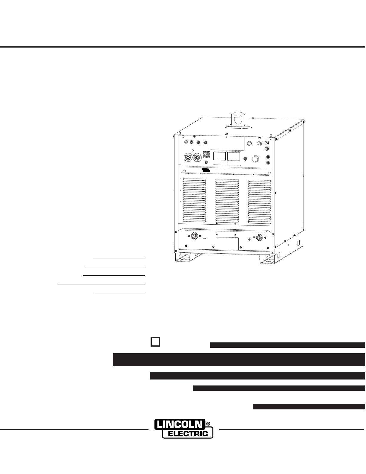
CV-525
L
I
N
C
OL
N
E
L
E
C
T
R
I
C
RETURN TO MAIN MENU
IM770
September, 2002
For use with machines having Code Numbers:
Safety Depends on You
Lincoln arc welding and cutting
equipment is designed and built
with safety in mind. However, your
overall safety can be increased by
proper installation ... and thoughtful operation on your part. DO
NOT INSTALL, OPERATE OR
REPAIR THIS EQUIPMENT
WITHOUT READING THIS
MANUAL AND THE SAFETY
PRECAUTIONS CONTAINED
THROUGHOUT. And, most
importantly, think before you act
and be careful.
A1677
CV-525
Date of Purchase:
Serial Number:
Code Number:
Model:
Where Purchased:
IEC 60974-1
IP 21S
S
OPERATOR’S MANUAL
Copyright © 2002 Lincoln Global Inc.
The Lincoln Electric Company (Australia) Pty. Ltd. 35 Bryant Street, Padstow, Sydney 2211, Australia Phone: (02) 9772-7222 FAX: (02) 9792-1387
• World's Leader in Welding and Cutting Products •
• Sales and Service through Subsidiaries and Distributors Worldwide •
Page 2

i
SAFETY
i
WARNING
CALIFORNIA PROPOSITION 65 WARNINGS
Diesel engine exhaust and some of its constituents
are known to the State of California to cause cancer, birth defects, and other reproductive harm.
The Above For Diesel Engines
ARC WELDING CAN BE HAZARDOUS. PROTECT YOURSELF AND OTHERS FROM POSSIBLE SERIOUS INJURY OR DEATH.
KEEP CHILDREN AWAY. PACEMAKER WEARERS SHOULD CONSULT WITH THEIR DOCTOR BEFORE OPERATING.
Read and understand the following safety highlights. For additional safety information, it is strongly recommended that you
purchase a copy of “Safety in Welding & Cutting - ANSI Standard Z49.1” from the American Welding Society, P.O. Box
351040, Miami, Florida 33135 or CSA Standard W117.2-1974. A Free copy of “Arc Welding Safety” booklet E205 is available
from the Lincoln Electric Company, 22801 St. Clair Avenue, Cleveland, Ohio 44117-1199.
BE SURE THAT ALL INSTALLATION, OPERATION, MAINTENANCE AND REPAIR PROCEDURES ARE
PERFORMED ONLY BY QUALIFIED INDIVIDUALS.
The engine exhaust from this product contains
chemicals known to the State of California to cause
cancer, birth defects, or other reproductive harm.
The Above For Gasoline Engines
FOR ENGINE
powered equipment.
1.a. Turn the engine off before troubleshooting and maintenance
work unless the maintenance work requires it to be running.
____________________________________________________
1.b. Operate engines in open, well-ventilated
areas or vent the engine exhaust fumes
outdoors.
____________________________________________________
1.c. Do not add the fuel near an open flame
welding arc or when the engine is running.
Stop the engine and allow it to cool before
refueling to prevent spilled fuel from vaporizing on contact with hot engine parts and
igniting. Do not spill fuel when filling tank. If
fuel is spilled, wipe it up and do not start
engine until fumes have been eliminated.
____________________________________________________
1.d. Keep all equipment safety guards, covers and devices in
position and in good repair.Keep hands, hair, clothing and
tools away from V-belts, gears, fans and all other moving
parts when starting, operating or repairing equipment.
____________________________________________________
1.e. In some cases it may be necessary to remove safety
guards to perform required maintenance. Remove
guards only when necessary and replace them when the
maintenance requiring their removal is complete.
Always use the greatest care when working near moving
parts.
___________________________________________________
1.f. Do not put your hands near the engine fan.
Do not attempt to override the governor or
idler by pushing on the throttle control rods
while the engine is running.
1.h. To avoid scalding, do not remove the
radiator pressure cap when the engine is
hot.
ELECTRIC AND
MAGNETIC FIELDS
may be dangerous
2.a. Electric current flowing through any conductor causes
localized Electric and Magnetic Fields (EMF). Welding
current creates EMF fields around welding cables and
welding machines
2.b. EMF fields may interfere with some pacemakers, and
welders having a pacemaker should consult their physician
before welding.
2.c. Exposure to EMF fields in welding may have other health
effects which are now not known.
2.d. All welders should use the following procedures in order to
minimize exposure to EMF fields from the welding circuit:
2.d.1.
Route the electrode and work cables together - Secure
them with tape when possible.
2.d.2. Never coil the electrode lead around your body.
2.d.3. Do not place your body between the electrode and
work cables. If the electrode cable is on your right
side, the work cable should also be on your right side.
___________________________________________________
1.g. To prevent accidentally starting gasoline engines while
turning the engine or welding generator during maintenance
work, disconnect the spark plug wires, distributor cap or
magneto wire as appropriate.
2.d.4. Connect the work cable to the workpiece as close as
possible to the area being welded.
2.d.5. Do not work next to welding power source.
Mar ‘95
Page 3

ii
SAFETY
ii
ELECTRIC SHOCK can
kill.
3.a. The electrode and work (or ground) circuits
are electrically “hot” when the welder is on.
Do not touch these “hot” parts with your bare
skin or wet clothing. Wear dry, hole-free
gloves to insulate hands.
3.b. Insulate yourself from work and ground using dry insulation.
Make certain the insulation is large enough to cover your full
area of physical contact with work and ground.
In addition to the normal safety precautions, if welding
must be performed under electrically hazardous
conditions (in damp locations or while wearing wet
clothing; on metal structures such as floors, gratings or
scaffolds; when in cramped positions such as sitting,
kneeling or lying, if there is a high risk of unavoidable or
accidental contact with the workpiece or ground) use
the following equipment:
• Semiautomatic DC Constant Voltage (Wire) Welder.
• DC Manual (Stick) Welder.
• AC Welder with Reduced Voltage Control.
3.c. In semiautomatic or automatic wire welding, the electrode,
electrode reel, welding head, nozzle or semiautomatic
welding gun are also electrically “hot”.
3.d. Always be sure the work cable makes a good electrical
connection with the metal being welded. The connection
should be as close as possible to the area being welded.
3.e. Ground the work or metal to be welded to a good electrical
(earth) ground.
ARC RAYS can burn.
4.a. Use a shield with the proper filter and cover
plates to protect your eyes from sparks and
the rays of the arc when welding or observing
open arc welding. Headshield and filter lens
should conform to ANSI Z87. I standards.
4.b. Use suitable clothing made from durable flame-resistant
material to protect your skin and that of your helpers from
the arc rays.
4.c. Protect other nearby personnel with suitable, non-flammable
screening and/or warn them not to watch the arc nor expose
themselves to the arc rays or to hot spatter or metal.
FUMES AND GASES
can be dangerous.
5.a. Welding may produce fumes and gases
hazardous to health. Avoid breathing these
fumes and gases.When welding, keep
your head out of the fume. Use enough
ventilation and/or exhaust at the arc to keep
fumes and gases away from the breathing zone. When
welding with electrodes which require special
ventilation such as stainless or hard facing (see
instructions on container or MSDS) or on lead or
cadmium plated steel and other metals or coatings
which produce highly toxic fumes, keep exposure as
low as possible and below Threshold Limit Values (TLV)
using local exhaust or mechanical ventilation. In
confined spaces or in some circumstances, outdoors, a
respirator may be required. Additional precautions are
also required when welding on galvanized steel.
3.f.
Maintain the electrode holder, work clamp, welding cable and
welding machine in good, safe operating condition. Replace
damaged insulation.
3.g. Never dip the electrode in water for cooling.
3.h. Never simultaneously touch electrically “hot” parts of
electrode holders connected to two welders because voltage
between the two can be the total of the open circuit voltage
of both welders.
3.i. When working above floor level, use a safety belt to protect
yourself from a fall should you get a shock.
3.j. Also see Items 6.c. and 8.
5.b.
Do not weld in locations near chlorinated hydrocarbon
coming from degreasing, cleaning or spraying operations.
The heat and rays of the arc can react with solvent vapors
form phosgene, a highly toxic gas, and other irritating
products.
5.c. Shielding gases used for arc welding can displace air and
cause injury or death. Always use enough ventilation,
especially in confined areas, to insure breathing air is safe.
5.d. Read and understand the manufacturer’s instructions for this
equipment and the consumables to be used, including the
material safety data sheet (MSDS) and follow your
employer’s safety practices. MSDS forms are available from
your welding distributor or from the manufacturer.
5.e. Also see item 1.b.
Mar ‘95
vapors
to
Page 4
iii
SAFETY
iii
WELDING SPARKS can
cause fire or explosion.
6.a.
Remove fire hazards from the welding area.
If this is not possible, cover them to prevent
the welding sparks from starting a fire.
materials from welding can easily go through small cracks
and openings to adjacent areas. Avoid welding near
hydraulic lines. Have a fire extinguisher readily available.
6.b. Where compressed gases are to be used at the job site,
special precautions should be used to prevent hazardous
situations. Refer to “Safety in Welding and Cutting” (ANSI
Standard Z49.1) and the operating information for the
equipment being used.
6.c. When not welding, make certain no part of the electrode
circuit is touching the work or ground. Accidental contact
can cause overheating and create a fire hazard.
6.d. Do not heat, cut or weld tanks, drums or containers until the
proper steps have been taken to insure that such procedures
will not cause flammable or toxic vapors from substances
inside. They can cause an explosion even
been “cleaned”. For information, purchase “Recommended
Safe Practices for the
Containers and Piping That Have Held Hazardous
Substances”, AWS F4.1 from the American Welding Society
(see address above).
6.e. Vent hollow castings or containers before heating, cutting or
welding. They may explode.
Sparks and spatter are thrown from the welding arc. Wear oil
6.f.
free protective garments such as leather gloves, heavy shirt,
cuffless trousers, high shoes and a cap over your hair. Wear
ear plugs when welding out of position or in confined places.
Always wear safety glasses with side shields when in a
welding area.
6.g. Connect the work cable to the work as close to the welding
area as practical. Work cables connected to the building
framework or other locations away from the welding area
increase the possibility of the welding current passing
through lifting chains, crane cables or other alternate circuits. This can create fire hazards or overheat lifting chains
or cables until they fail.
6.h. Also see item 1.c.
Remember that welding sparks and hot
though
they have
Preparation
for Welding and Cutting of
CYLINDER may explode
if damaged.
7.a. Use only compressed gas cylinders
containing the correct shielding gas for the
process used and properly operating
regulators designed for the gas and
pressure used. All hoses, fittings, etc. should be suitable for
the application and maintained in good condition.
7.b. Always keep cylinders in an upright position securely
chained to an undercarriage or fixed support.
7.c. Cylinders should be located:
• Away from areas where they may be struck or subjected to
physical damage.
• A safe distance from arc welding or cutting operations and
any other source of heat, sparks, or flame.
7.d. Never allow the electrode, electrode holder or any other
electrically “hot” parts to touch a cylinder.
7.e. Keep your head and face away from the cylinder valve outlet
when opening the cylinder valve.
7.f. Valve protection caps should always be in place and hand
tight except when the cylinder is in use or connected for
use.
7.g. Read and follow the instructions on compressed gas
cylinders, associated equipment, and CGA publication P-l,
“Precautions for Safe Handling of Compressed Gases in
Cylinders,” available from the Compressed Gas Association
1235 Jefferson Davis Highway, Arlington, VA 22202.
FOR ELECTRICALLY
powered equipment.
8.a. Turn off input power using the disconnect
switch at the fuse box before working on
the equipment.
8.b. Install equipment in accordance with the U.S. National
Electrical Code, all local codes and the manufacturer’s
recommendations.
8.c. Ground the equipment in accordance with the U.S. National
Electrical Code and the manufacturer’s recommendations.
Mar ‘95
Page 5

iv
SAFETY
iv
PRÉCAUTIONS DE SÛRETÉ
Pour votre propre protection lire et observer toutes les instructions et les précautions de sûreté specifiques qui parraissent
dans ce manuel aussi bien que les précautions de sûreté
générales suivantes:
Sûreté Pour Soudage A L’Arc
1. Protegez-vous contre la secousse électrique:
a. Les circuits à l’électrode et à la piéce sont sous tension
quand la machine à souder est en marche. Eviter toujours
tout contact entre les parties sous tension et la peau nue
ou les vétements mouillés. Porter des gants secs et sans
trous pour isoler les mains.
b. Faire trés attention de bien s’isoler de la masse quand on
soude dans des endroits humides, ou sur un plancher
metallique ou des grilles metalliques, principalement dans
les positions assis ou couché pour lesquelles une
grande partie du corps peut être en contact avec la
masse.
c. Maintenir le porte-électrode, la pince de masse, le câble
de soudage et la machine à souder en bon et sûr état
defonctionnement.
d.Ne jamais plonger le porte-électrode dans l’eau pour le
refroidir.
e. Ne jamais toucher simultanément les parties sous tension
des porte-électrodes connectés à deux machines à souder parce que la tension entre les deux pinces peut être le
total de la tension à vide des deux machines.
f. Si on utilise la machine à souder comme une source de
courant pour soudage semi-automatique, ces precautions
pour le porte-électrode s’applicuent aussi au pistolet de
soudage.
5. Toujours porter des lunettes de sécurité dans la zone de
soudage. Utiliser des lunettes avec écrans lateraux dans les
zones où l’on pique le laitier.
6. Eloigner les matériaux inflammables ou les recouvrir afin de
prévenir tout risque d’incendie dû aux étincelles.
7. Quand on ne soude pas, poser la pince à une endroit isolé de
la masse. Un court-circuit accidental peut provoquer un
échauffement et un risque d’incendie.
8. S’assurer que la masse est connectée le plus prés possible
de la zone de travail qu’il est pratique de le faire. Si on place
la masse sur la charpente de la construction ou d’autres
endroits éloignés de la zone de travail, on augmente le risque
de voir passer le courant de soudage par les chaines de levage, câbles de grue, ou autres circuits. Cela peut provoquer
des risques d’incendie ou d’echauffement des chaines et des
câbles jusqu’à ce qu’ils se rompent.
9. Assurer une ventilation suffisante dans la zone de soudage.
Ceci est particuliérement important pour le soudage de tôles
galvanisées plombées, ou cadmiées ou tout autre métal qui
produit des fumeés toxiques.
10. Ne pas souder en présence de vapeurs de chlore provenant
d’opérations de dégraissage, nettoyage ou pistolage. La
chaleur ou les rayons de l’arc peuvent réagir avec les
vapeurs du solvant pour produire du phosgéne (gas fortement toxique) ou autres produits irritants.
11. Pour obtenir de plus amples renseignements sur la sûreté,
voir le code “Code for safety in welding and cutting” CSA
Standard W 117.2-1974.
2. Dans le cas de travail au dessus du niveau du sol, se protéger contre les chutes dans le cas ou on recoit un choc. Ne
jamais enrouler le câble-électrode autour de n’importe quelle
partie du corps.
3. Un coup d’arc peut être plus sévère qu’un coup de soliel,
donc:
a. Utiliser un bon masque avec un verre filtrant approprié
ainsi qu’un verre blanc afin de se protéger les yeux du
rayonnement de l’arc et des projections quand on soude
ou quand on regarde l’arc.
b. Porter des vêtements convenables afin de protéger la
peau de soudeur et des aides contre le rayonnement de
l‘arc.
c. Protéger l’autre personnel travaillant à proximité au
soudage à l’aide d’écrans appropriés et non-inflammables.
4. Des gouttes de laitier en fusion sont émises de l’arc de
soudage. Se protéger avec des vêtements de protection
libres de l’huile, tels que les gants en cuir, chemise épaisse,
pantalons sans revers, et chaussures montantes.
PRÉCAUTIONS DE SÛRETÉ POUR
LES MACHINES À SOUDER À
TRANSFORMATEUR ET À
REDRESSEUR
1. Relier à la terre le chassis du poste conformement au code
de l’électricité et aux recommendations du fabricant. Le dispositif de montage ou la piece à souder doit être branché à
une bonne mise à la terre.
2. Autant que possible, I’installation et l’entretien du poste
seront effectués par un électricien qualifié.
3. Avant de faires des travaux à l’interieur de poste, la
debrancher à l’interrupteur à la boite de fusibles.
4. Garder tous les couvercles et dispositifs de sûreté à leur
place.
Mar. ‘93
Page 6

v
ELECTROMAGNETIC COMPATIBILITY (EMC)
Conformance
Products displaying the CE mark are in conformity with European Community Council Directive of 3 May
1989 on the approximation of the laws of the Member States relating to electromagnetic compatibility
(89/336/EEC). It was manufactured in conformity with a national standard that implements a harmonized
standard: EN 50 199 Electromagnetic Compatibility (EMC) Product Standard for Arc Welding Equipment. It
is for use with other Lincoln Electric equipment. It is designed for industrial and professional use.
Introduction
All electrical equipment generates small amounts of electromagnetic emission. Electrical emission may be
transmitted through power lines or radiated through space, similar to a radio transmitter. When emissions are
received by other equipment, electrical interference may result. Electrical emissions may affect many kinds of
electrical equipment; other nearby welding equipment, radio and TV reception, numerical controlled machines,
telephone systems, computers, etc. Be aware that interference may result and extra precautions may be required
when a welding power source is used in a domestic establishment.
SAFETY
v
Installation and Use
The user is responsible for installing and using the welding equipment according to the manufacturer s instructions.
If electromagnetic disturbances are detected then it shall be the responsibility of the user of the welding equipment
to resolve the situation with the technical assistance of the manufacturer. In some cases this remedial action may
be as simple as earthing (grounding) the welding circuit, see Note. In other cases it could involve constructing an
electromagnetic screen enclosing the power source and the work complete with associated input filters. In all cases
electromagnetic disturbances must be reduced to the point where they are no longer troublesome.
Note: The welding circuit may or may not be earthed for safety reasons according to national codes.
Changing the earthing arrangements should only be authorized by a person who is competent to
assess whether the changes will increase the risk of injury, e.g., by allowing parallel welding
current return paths which may damage the earth circuits of other equipment.
Assessment of Area
Before installing welding equipment the user shall make an assessment of potential electromagnetic problems in the
surrounding area. The following shall be taken into account:
a) other supply cables, control cables, signaling and telephone cables; above, below and adjacent to the
welding equipment;
b) radio and television transmitters and receivers;
c) computer and other control equipment;
d) safety critical equipment, e.g., guarding of industrial equipment;
e) the health of the people around, e.g., the use of pacemakers and hearing aids;
f) equipment used for calibration or measurement;
g) the immunity of other equipment in the environment. The user shall ensure that other equipment being
used in the environment is compatible. This may require additional protection measures;
h) the time of day that welding or other activities are to be carried out.
3-1-96H
L10093
Page 7

vi
ELECTROMAGNETIC COMPATIBILITY (EMC)
The size of the surrounding area to be considered will depend on the structure of the building and other activities
that are taking place. The surrounding area may extend beyond the boundaries of the premises.
Methods of Reducing Emissions
Mains Supply
Welding equipment should be connected to the mains supply according to the manufacturer s recommendations.
If interference occurs, it may be necessary to take additional precautions such as filtering of the mains supply.
Consideration should be given to shielding the supply cable of permanently installed welding equipment, in metallic
conduit or equivalent. Shielding should be electrically continuous throughout its length. The shielding should be
connected to the welding power source so that good electrical contact is maintained between the conduit and the
welding power source enclosure.
Maintenance of the Welding Equipment
The welding equipment should be routinely maintained according to the manufacturer s recommendations. All
access and service doors and covers should be closed and properly fastened when the welding equipment is in
operation. The welding equipment should not be modified in any way except for those changes and adjustments
covered in the manufacturers instructions. In particular, the spark gaps of arc striking and stabilizing devices should
be adjusted and maintained according to the manufacturer s recommendations.
SAFETY
vi
Welding Cables
The welding cables should be kept as short as possible and should be positioned close together, running at or close
to the floor level.
Equipotential Bonding
Bonding of all metallic components in the welding installation and adjacent to it should be considered. However,
metallic components bonded to the work piece will increase the risk that the operator could receive a shock by
touching these metallic components and the electrode at the same time. The operator should be insulated from all
such bonded metallic components.
Earthing of the Workpiece
Where the workpiece is not bonded to earth for electrical safety, not connected to earth because of its size and
position, e.g., ships hull or building steelwork, a connection bonding the workpiece to earth may reduce emissions
in some, but not all instances. Care should be taken to prevent the earthing of the workpiece increasing the risk
of injury to users, or damage to other electrical equipment. Where necessary, the connection of the wor kpiece to
earth should be made by a direct connection to the workpiece, but in some countries where direct connection is not
permitted, the bonding should be achieved by suitable capacitance, selected according to national regulations.
Screening and Shielding
Selective screening and shielding of other cables and equipment in the surrounding area may alleviate problems of
interference. Screening of the entire welding installation may be considered for special applications.
1
Portions of the preceding text are contained in EN50199: "Electromagnetic Compatibility (EMC) product standard for
arc welding equipment."
1
3-1-96H
L10093
Page 8
vii
for selecting a QUALITY product by Lincoln Electric. We want you
Thank You
to take pride in operating this Lincoln Electric Company product
••• as much pride as we have in bringing this product to you!
Please Examine Carton and Equipment For Damage Immediately
When this equipment is shipped, title passes to the purchaser upon receipt by the carrier. Consequently, Claims
for material damaged in shipment must be made by the purchaser against the transportation company at the
time the shipment is received.
Please record your equipment identification information below for future reference. This information can be
found on your machine nameplate.
Model Name & Number _____________________________________
Code & Serial Number _____________________________________
Date of Purchase _____________________________________
Whenever you request replacement parts for or information on this equipment always supply the information
you have recorded above.
vii
Read this Operators Manual completely before attempting to use this equipment. Save this manual and keep it
handy for quick reference. Pay particular attention to the safety instructions we have provided for your protection.
The level of seriousness to be applied to each is explained below:
WARNING
This statement appears where the information must be followed exactly to avoid serious personal injury or
loss of life.
CAUTION
This statement appears where the information must be followed to avoid minor personal injury or damage to
this equipment.
Page 9

viii
TABLE OF CONTENTS
Page
Installation.......................................................................................................................Section A
Technical Specifications.......................................................................................................A-1
Safety Precautions. ..............................................................................................................A-2
Selected Suitable Location............................................................................................A-2
Application Limitations ..................................................................................................A-2
Stacking ........................................................................................................................A-2
Input Power Connections..............................................................................................A-2
Outout Cable Connections............................................................................................A-3
Installation of Field Installed Options ............................................................................A-3
Capacitor Discharge Circuit ..........................................................................................A-3
Installation of Equipment for Recommended Processes ..............................................A-4
________________________________________________________________________________
Operation.........................................................................................................................Section B
Meaning of Graphic Symbols .................................................................................B-1,thru B-3
Safety Precautions ...............................................................................................................B-4
General Description..............................................................................................................B-4
Recommended Processes and Equipment..........................................................................B-4
Arc Characteristics........................................................................................................B-4
Input Contactor..............................................................................................................B-5
Auxiliary Power Connections ........................................................................................B-5
Remote Control Connections........................................................................................B-5
Gas Heater Connector ..................................................................................................B-5
Output Connections ......................................................................................................B-5
Input Connections .........................................................................................................B-5
Input Line Voltage Compensation.................................................................................B-5
Solid Sate Output Control .............................................................................................B-6
Solid State Control Systems..........................................................................................B.6
Machine Cooling ...........................................................................................................B-6
Case Features...............................................................................................................B-6
Parralleling ....................................................................................................................B-6
Diode Option .................................................................................................................B-6
Machine And Circuit Protection.....................................................................................B-6
Power Source Operation......................................................................................................B-7
Control Settings and Descriptions .................................................................................B-7,B-8
Control Features on Feeder Interface Board........................................................................B-9
________________________________________________________________________________
viii
Accessories.....................................................................................................Section C
Semi-Automatic Wire Feeders...............................................................................C-1
Automatic wire Feeders.........................................................................................C-1
Field Installed Options.........................................................................................................
C-1
________________________________________________________________________
Maintenance ....................................................................................................Section D
Safety Precautions ................................................................................................D-1
General Maintenance............................................................................................D-1
________________________________________________________________________
Troubleshooting..............................................................................................Section E
Safety Precautions.................................................................................................E-1
How to Use Troubleshooting Guide.......................................................................E-1
Troubleshooting Guide.............................................................................E-2 thru E-4
________________________________________________________________________
Wiring Diagrams..............................................................................................Section F
________________________________________________________________________
Parts Pages.............................................................................................................P-475
Page 10

A-1
INSTALLATION
TECHNICAL SPECIFICATIONS CV-525 KA1454-1, KA1454-2
INPUT - THREE PHASE ONLY
Standard
Voltage
100% Duty Cycle
Input Current at Rated Output
60% Duty Cycle
50% Duty Cycle
A-1
45% Duty Cycle
380-415V/50/60Hz (KA1454-1)
220/380-415/440V/50/60Hz (KA1454-2)
Duty Cycle
100% Duty Cycle
60% Duty Cycle
50% Duty Cycle
45% Duty Cycle
Current Range
60-525
RECOMMENDED INPUT WIRE AND FUSE SIZES
INPUT
VOLTAGE
380-415V
220/380-415/440V
FREQUENCY
Hz
50/60
50/60
45
77/45/39
47
81/47/40
RATED OUTPUT
Amps
400
450
500
525
OUTPUT
Maximum Open Circuit Voltage
46
INPUT AMPERE
RATING ON
NAMEPLATE
50
86/50/43
TYPE 75°C
COPPER WIRE
IN CONDUIT
AWG(IEC-MM2) SIZES
40°C (104°F) Ambient
6 (16)
4(25)/6(16)6(16)
48
83/48/41
Volts at Rated Amperes
34
36.5
39
40.25
Auxiliary
36VAC-10Amps
for Gas Regulator
use only
TYPE 75°C
GROUND WIRE
IN CONDUIT
AWG(IEC-MM2) SIZES
8 (10)
6(16)/8(10)/8(10)
49
84/49/42
Power
TYPE 75°C
(SUPER LAG)
OR BREAKER
SIZE (AMPS)
100A
175A/100A/80A
1
PHYSICAL DIMENSIONS
HEIGHT
27.5 in
699 mm
1
Also called “inverse time” or “thermal/magnetic” circuit breakers; circuit breakers which have a delay in tripping action that decreases as the magnitude of the current increases.
WIDTH
22.25 in
565 mm
DEPTH
32.0 in
813 mm
WEIGHT
385 lbs.
175 kg.
CV-525
Page 11
A-2
INSTALLATION
A-2
Read entire installation section before starting
installation.
SAFETY PRECAUTIONS
WARNING
ELECTRIC SHOCK can kill.
•Only qualified personnel should
perform this installation.
•Turn the input power OFF at the
disconnect switch or fuse box
before working on this equipment.
• Turn the Power switch on the CV-525 “OFF”
before connecting or disconnecting output
cables, wire feeder or remote connections, or
other equipment.
• Do not touch electrically hot parts.
• Always connect the Idealarc CV-525 grounding
terminal (located on the welder near the reconnect panel) to a good electrical earth ground.
-----------------------------------------------------------------------
SELECT SUITABLE LOCATION
The machine should be located in a clean, dry place
where there is free circulation of clean air such that air
movement in through the front and out through the
back will not be restricted. Dirt and dust that can be
drawn into the machine should be kept to a minimum.
Failure to observe these precautions can result in
excessive operating temperatures and nuisance shutdown of the machine.
STACKING
WARNING
FALLING EQUIPMENT can cause
injury.
• Do not lift this machine using lift
bale if it is equipped with a heavy
accessory such as trailer or gas
cylinder.
• Lift only with equipment of adequate lifting
capacity.
• Be sure machine is stable when lifting.
• Do not stack more than three high.
• Do not stack the CV-525 on top of any other
machine.
----------------------------------------------------------------------
The units may be stacked three high by observing the
following safety precautions.
A. Make sure the first or bottom unit is setting on a
level, well supported surface.
B. The units must be stacked with their fronts flush,
making sure the two holes in the base rails of the
unit being stacked on top are over the two holes
located on the top front corners of the unit it is
being stacked on. Fasten the units together with
8mm diameter bolts, nuts and lockwashers
through these holes.
C. Remove fastening bolts before lifting unit off stacks.
INPUT POWER CONNECTIONS
APPLICATION LIMITATIONS
There are no provisions on the CV-525 for paralleling,
and outdoor operations without rain sheltering is not
recommended.
By removing the rear access panel the three phase
input power is connected to the three line terminals on
the input contactor, and the earth grounding lead to
the grounding terminal on the input box floor marked
with the symbol.
CV-525
Page 12

A-3
)
INSTALLATION
A-3
CAUTION
Failure to follow these instructions can cause immediate failure of components within the machine.
When powering welder from a generator be sure to
turn off the welder first, before generator is shut down
in order to prevent damage to welder.
------------------------------------------------------------------------
OUTPUT CABLE CONNECTIONS
The output terminals are marked "+" and "-". The CV
525 provides stud connection for cable lugs.
OUTPUT CABLES
CABLE SIZES FOR COMBINED LENGTH OF
ELECTRODE AND WORK CABLE
MACHINE LOAD
CABLE LENGTHS
UP TO 50 ft
(15m)
50 to 100 ft
(15-30 m)
400A
(100% DUTY
CYCLE)
3/0
85 mm
2
3/0
85 mm
2
500A
(50% DUTY
CYCLE)
2/0
67 mm
2
2/0
67 mm
2
The K857 has a 6-pin MS-style connector. The K857
requires a K864 adapter cable which connects to the
14-pin connector on the machine.
REMOTE CONTROL ADAPTER CABLE (K864)
STRAIGHT PLUG (14 PIN)
TO POWER SOURCE
CABLE RECEPTACLE (6 SOCKET)
TO: K857 REMOTE CONTROL
CABLE RECEPTACLE (14 SOCKET
TO: LN-7 WIRE FEEDERS
A “V” cable 12” (.30m) long to connect a K857
Remote Control (6 pin connector) with a wire-feeder
(14-pin connector) and the machine (14-pin connector). If a remote control is used alone the wire-feeder
connection is then not used.
WARNING
ELECTRIC SHOCK can kill.
• Turn the power switch of the welding
power source “OFF” before installing
plugs on cables or when connecting
or disconnecting plugs to welding
power source.
------------------------------------------------------------
100-150 ft
(30-46 m)
150-200 ft
(46-61 m)
200-250 ft
(67-76 m)
3/0
85 mm
3/0
85 mm
4/0
107 mm
2
2
2
3/0
85 mm
3/0
85 mm
4/0
107 mm
2
2
2
INSTALLATION OF FIELD INSTALLED OPTIONS
REMOTE OUTPUT CONTROL
(K857 WITH K864 ADAPTER OR K775 )
Extreme caution must be observed when installing or
extending the wiring of a remote control. Improper
connection of this unit can lead to loss of control
and/or poor welding. Only the green lead can and
should be grounded to the machine case. When
extending the standard remote control, make sure the
leads are the same and the splice is waterproof. Be
very careful not to ground the cable when in use and
don’t let the lugs touch against the case.
CAPACITOR DISCHARGE CIRCUIT (K828-1)
This circuit mounts inside the CV-525 and is
Recommended when:
1) CV-525 is used in conjunction with any LN-23P or
older LN-8 or LN-9 semiautomatic wire-feeder.
Eliminates possible arc flash re-start of weld when
trigger interlock is used. Not required with current
LN-8 (above Code 8700), or LN-9’s with serial
numbers above 115187 (manufactured after
12/83), or any LN-9 having an L6043-1 Power PC
Board.
2) CV-525 is used with an LN-22 equipped with an
older K279 Contactor-Voltage Control Option.
Eliminates electrode overrun when gun trigger is
released. Not required when later K279 (above
Code 8800) is used.
3) CV-525 is used with any semiautomatic wire-feed-
er and possible small spark, if electrode touches
work just after gun trigger is released, is objectionable.
Install per M17060 instructions included with the
Kit.
CV-525
Page 13

A-4
INSTALLATION
Installation of Equipment Required for
Recommended Processes
A-4
CONNECTION OF CV-525 TO ARCWELD AWF
FEEDERS, OR PANASONIC STYLE / OTC STYLE
WIRE FEEDERS.
Note: Only one wire feeder should be connected to the
CV-525 power source. If two or more are connected to
the CV-525 power source it will not work properly.
WIRE FEEDER CONTROL CABLE CONNECTIONS
For control cable with WF-L(14-pin) connector:
Connect control cable to WF-L connector on the front
panel of the machine labeled WF-L. See the appropriate connection diagram for the exact instructions for
the wire feeder being used. Refer to “115VAC and
42VAC Auxiliary Power and Control Connections”
section for connector pin functions.
A cover (Lincoln Electric Part Number S17062-3) is
available for the unused WF-L connector to protect it
against dirt and moisture.
CONNECTION OF CV-525 TO LN-22 OR LN-25
a) Turn off all power.
b) Connect a jumper between pins “C to D” in WF-L
connector plug, (a K484 14-pin jumper plug is
available).
a) Turn off all power.
b) Connect the ARCWELD AWF or Panasonic Style
wire feeder to WF-AWF/P receptacle. Connect
OTC style wire feeder to WF-O receptacle.
c) Place the output control switch to the “REMOTE”
position.
d) Turn on the input power. The Feeder Ready LED
should lit up if one of the wire feeders listed in
step (b) is connected correctly to the CV-525.
c) Connect the electrode cable to the output terminal
of polarity required by electrode. Connect the work
lead to the other terminal.
d) Place the OUTPUT CONTROL Switch at “LOCAL”
position unless a Remote Control is connected to
the CV-525.
NOTE: The output terminals are energized at all
times.
The Feeder Ready LED will stay off when a wire feeder is connected to the WF-L connector.
CV-525
Page 14

B-1
OPERATION
B-1
MEANINGS OF GRAPHIC SYMBOLS
The CV-525 nameplate has been designed to use international symbols in describing the function of the various
components. Below are the symbols used.
POWER ON-OFF SWITCH
Input (Power)
On
Off
OUTPUT CONTROL DIAL
V
OUTPUT CONTROL “LOCAL-REMOTE” SWITCH
Output Voltage Control (Export Model)
Increase / Decrease of Output Voltage
Remote Output Voltage Control
Local Output Voltage Control
CV-525
Page 15

B-2
CIRCUIT BREAKER
THERMAL PROTECTION LIGHT
VOLTMETER SWITCH
OPERATION
Circuit Breaker
High Temperature
Voltmeter
Positive Electrode
B-2
Negative Electrode
WARNING IDENTIFICATION
Warning Identification
EARTH GROUND CONNECTION
Signifying the Earth (Ground) Connection
CHASSIS GROUND CONNECTION
Signifying the Chassis (Ground) Connection
SYMBOLS USED ON NAMEPLATES, AREAS ON THE MACHINE AND IN THIS MANUAL
A
Gas Purge
Crater Current
CV-525
Page 16

B-3
V
OPERATION
Three Phase Power
Transformer
Rectifier
Rectified DC Output
Constant Voltage Characteristic
B-3
t
Line Connection
Shielded Metal Arc Welding
Flux Cored Arc Welding
Crater Voltage
Wire Feeder
Spot Weld
2-Step
4-Step
t
Burn Back
Run In Speed
CV-525
Page 17

B-4
OPERATION
SAFETY PRECAUTIONS
Read and understand this entire section before operating the machine.
WARNING
ELECTRIC SHOCK
can kill.
• Do not touch electrically live parts
or electrode with skin or wet
clothing.
• Insulate yourself from work and
ground.
• Always wear dry insulating
gloves.
B-4
GENERAL DESCRIPTION
The CV-525 is an SCR controlled DC power source with
a single range potentiometer control of the voltage output. The primary voltage is 380-415VAC 50/60Hz for single input voltage machine and 220/380-415/440V
50/60Hz for triple input voltage machine. The power
source complies with IEC 60974-1 requirements.
The CV-525 base model is shipped with a standard control panel and an advanced control panel is available as
field-installed option. The main new feature of this product is it works with Arcweld AWF wire feeders, Panasonic
and OTC style cable-driven wire feeders as well as
Lincoln’s standard wire feeders. Control functions like
Gas Purge, 2T/4T trigger, and Crater Fill Settings are
part of the front Panel for Arcweld AWF wire feeders.
The control functions on the optional panel include Spot
Weld ON/OFF and Timer, Run-in Speed Setting, and
Burn-back Timer.
FUMES AND GASES
can be dangerous.
• Keep your head out of fumes.
• Use ventilation or exhaust to
remove fumes from breathing
zone.
WELDING SPARKS
can cause fire or
explosion
• Keep flammable material away.
• Do not weld on containers that
have held combustibles.
ARC RAYS
can burn.
• Wear eye, ear and body
protection.
Observe additional Safety Guidelines detailed
throughout this manual.
CV-525 interface with Panasonic style or OTC style wire
feeder through two different 6-pin connectors labeled as
WF-AWF/P and WF-O. Cold inch, wire feed speed and
arc voltage can be set on their feeder control panel. Cold
inch, wire feed speed, arc voltage and gas purge can all
be set remotely on the feeder control panel of the
Arcweld AWF wire feeder. The plug-in of a Panasonic
style or OTC style wire feeder will be auto-sensed and
indicated with the feeder ready light on the front panel.
A receptacle of 36VAC auxiliary power and a circuit
breaker are located at the back of the machine for gas
heaters.
RECOMMENDED PROCESSES
& EQUIPMENT
The CV-525 is recommended for use with all the procedures of solid wire Gas Metal-Arc, cored wire outershield GMA as well as Innershield process within its
capacity of 60 to 525 amps.
This power source is designed to work with Lincoln’s
Automatic wire feeders and semiautomatic wire feeders with the control cable having a 14 pin Amphenol
connector. It is also designed to work with the cabledriven Panasonic
Arcweld AWF
style
, OTC
style
wire feeders and
wire feeder AWF-2 and AWF-4.
the
ARC CHARACTERISTICS
Through the unique combination of the transformer,
three phase semiconverter rectifier, capacitor bank,
and output choke design, in conjunction with the solid
state control system, an outstanding constant voltage
welding performance is achieved with a fixed pinch
setting optimized for the most popular arc characteristics.
CV-525
Page 18

B-5
F=76
G=75
H=21
I=41
J=31
K=42
A=32
B=GND
C=2
D=4
E=77
LN
M
INPUT CONTACTOR
OPERATION
REMOTE CONTROL CONNECTIONS
B-5
The power source is equipped with an input contactor.
115 VAC and 42 VAC AUXILIARY POWER AND
CONTROL CONNECTIONS
14-Pin Connector
The power source is equipped to furnish nominally
115 volt AC and 42 volt AC auxiliary power for operating wire feeding equipment, etc. The auxiliary power is
available at the 14-pin MS-style connector receptacle
on the control panel 115V AC is available at receptacle pins A and J. 42V AC is available at receptacle
pins I and K. The 115V AC and the 42V AC are isolated circuits and each is protected by a 10 amp circuit
breaker. A toggle switch on the control panel selects
115V AC or 42V AC to the receptacle.
FRONT VIEW OF 14-PIN CONNECTOR
RECEPTACLE
Remote control connections are available both at a
14-pin connector receptacle located on the control
panel for standard Lincoln wire feeders and the two 6pin receptacles for Asian style wire feeders.
GAS HEATER CONNECTOR
A standard 3-pin receptacle located on the rear panel
for supplying 36VAC to a gas heater. A 10 amp circuit
breaker which is also located on the rear panel protects this circuit.
OUTPUT CONNECTIONS
The output terminals are recessed on the case front
and labeled “+” and “-”. The CV-525 provides stud terminals for output cables.
INPUT CONNECTIONS (See Table B.1)
The three input lines are brought in through the rear
panel of the power source and attached to the input
contactor. Removal of the removable access panel
makes the contactor accessible for the input cable
connections.
PIN LEAD NO. FUNCTION
A32
B GND Chassis Connection
C 2 Trigger Circuit
D 4 Trigger Circuit
E 77 Output Control
F 76 Output Control
G 75 Output Control
H 21 Work Connection
I 41 42 VAC
J31
K 42 42 VAC
L --- --M --- --N --- ---
115 VAC (Export Model Only)
115 VAC (Export Model Only)
INPUT LINE VOLTAGE COMPENSATION
The power source is equipped with input line voltage
compensation as standard. For a line voltage fluctuation of ±10% the output will remain essentially constant. This is accomplished through the feedback network in the control circuit.
CV-525
Page 19

B-6
OPERATION
B-6
TABLE B.1
LINK POSITIONS
LINK POSITIONS
LINK POSITIONS
AM3237-1
MOVABLE LINK POSITIONS INDICATED
BY ARROWED LINE
INPUT SUPPLY CONNECTION DIAGRAM
CAUTION: ALL INPUT POWER MUST BE ELECTRICALLY DISCONNECTED BEFORE TOUCHING PANEL. NOTE: MACHINES ARE SHIPPED FROM FACTORY CONNECTED FOR HIGHEST VOLTAGE.
CONNECTION FOR 460 VOLTS 50/60Hz.
1/ ON RECONNECT PANEL, LOOSEN ALL HEX BOLTS, PULL BACK MOVABLE LINKS, AND ROTATE
TAPE
}
H2
H3
H4
LINKS TO THEIR NEW POSITIONS. POPSITION EACH LINK BETWEEN THE WIRE TERMINAL AND HEX
L3
BOLT, PUSH THE LINK COMPLETELY FORWARD, SECURELY TIGHTEN ALL HEX BOLTS.
DO NOT REMOVE HEX BOLTS AT ANY TIME.
1CR
L2
INPUT
LINES
CONNECTION FOR 380-415 VOLTS 50/60Hz.
2/ CONNECT L1, L2 & L3 INPUT SUPPLY LINES & H1 & H4 CONTROL TRANSFORMER LEADS TO INPUT
SIDE OF 1CR STARTER AS SHOWN.
3/ INSULATE THE UNUSED H2, H3 LEAD TERMINALS WITH ADEQUATE TAPE TO PROVIDE AT LEAST
600V. INSULATION.
4/ CONNECT TERMINAL MARKED TO GROUND PER NATIONAL ELECTRICAL CODE.
RECONNECT PANEL
H1
L1
GND
1/ ON RECONNECT PANEL, LOOSEN ALL HEX BOLTS, PULL BACK MOVABLE LINKS, AND ROTATE
TAPE
}
H2
H4
H3
LINKS TO THEIR NEW POSITIONS. POPSITION EACH LINK BETWEEN THE WIRE TERMINAL AND HEX
BOLT, PUSH THE LINK COMPLETELY FORWARD, SECURELY TIGHTEN ALL HEX BOLTS.
L3
DO NOT REMOVE HEX BOLTS AT ANY TIME.
1CR
L2
INPUT
LINES
2/ CONNECT L1, L2 & L3 INPUT SUPPLY LINES & H1 & H4 CONTROL TRANSFORMER LEADS TO INPUT
SIDE OF 1CR STARTER AS SHOWN.
3/ INSULATE THE UNUSED H2, H4 LEAD TERMINALS WITH ADEQUATE TAPE TO PROVIDE AT LEAST
600V. INSULATION.
4/ CONNECT TERMINAL MARKED TO GROUND PER NATIONAL ELECTRICAL CODE.
H1
L1
GND
RECONNECT PANEL
CONNECTION FOR 230 VOLTS 50/60Hz.
TAPE
}
H3
H4
1/ ON RECONNECT PANEL, LOOSEN ALL HEX BOLTS, PULL BACK MOVABLE LINKS, AND ROTATE
LINKS TO THEIR NEW POSITIONS. POPSITION EACH LINK BETWEEN THE WIRE TERMINAL AND HEX
BOLT, PUSH THE LINK COMPLETELY FORWARD, SECURELY TIGHTEN ALL HEX BOLTS.
DO NOT REMOVE HEX BOLTS AT ANY TIME.
1CR
H2
L2
L3
INPUT
LINES
A18-9-02M
2/ CONNECT L1, L2 & L3 INPUT SUPPLY LINES & H1 & H4 CONTROL TRANSFORMER LEADS TO INPUT
SIDE OF 1CR STARTER AS SHOWN.
3/ INSULATE THE UNUSED H3, H4 LEAD TERMINALS WITH ADEQUATE TAPE TO PROVIDE AT LEAST
600V. INSULATION.
4/ CONNECT TERMINAL MARKED TO GROUND PER NATIONAL ELECTRICAL CODE.
RECONNECT PANEL
H1
L1
GND
FOR TRANSFORMER LEAD CONNECTIONS REFER AS3324
THE LINCOLN ELECTRIC CO., AUSTRALIA (PTY.LTD.)
CV-525
Page 20

B-7
OPERATION
B-7
SOLID STATE OUTPUT CONTROL
The output of the welder is electronically controlled by
SCR’s instead of mechanical contactors, providing extra
long life for highly repetitive welding applications.
SOLID STATE CONTROL SYSTEM
The Control PC Board is located behind the control panel
which hinges down for easy access to the board. The
Snubber PC Board is mounted on the back of the case
front. The feeder interface board and the motor drive
board are located next to the control PC board.
MACHINE COOLING
The fan pulls air in through the louvered front of the
machine over the internal parts and exhausts out the louvered rear of the machine. The fan motor is fully
enclosed, has sealed ball bearings, requires no lubrication, and operates when the power switch is turned on.
CASE FEATURES
The machine depth is 813mm. The low profile case facilitates installation of the machine under a workbench and
stacking the machines three high to conserve floor
space.
The case front incorporates a recessed hinged control
panel where all the machine controls are mounted. This
recessed panel protects the controls and minimizes the
possibilities of accidental contact. This control panel can
be easily opened to permit access to the enclosed section which PC boards. The output lead terminals are also
recessed to avoid any object or person accidentally coming in contact with an output terminal.
The individual case sides are removable for easy access for
internal service or inspection. These are removable even
though the machines are stacked three high.
The case rear, top section, is equipped with a removable
access panel. This provides easy access to the input contactor, easy connection and reconnection of input leads, and
easy access for service or inspection.
Although the machine is designed for use in rain-sheltered
environments, the transformer and choke assembly are
dipped in a special corrosion resistant epoxy paint.
PARALLELING
There are no provisions on the CV-525 to permit paralleling.
DIODE OPTION (Factory installed only)
The CV-525 Diode option is required to utilize the cold start
and cold electrode sensing features of the NA-3, NA-5 or
NA-5R. When this option is not used with an NA-3, NA-5 or
NA-5R, see the CV-525 / NA-3, CV-525 / NA-5 or CV-525 /
NA-5R connection diagram for instructions on how to disable this circuit. If the circuit is not disabled, the wire cannot
be inched down.
MACHINE & CIRCUIT PROTECTION
(THERMAL PROTECTION LIGHT)
The power source is thermostatically protected with proximity thermostats against overload or insufficient cooling. One
thermostat is located on the nose of the center bottom primary coil and a second thermostat is attached to the lead
connecting the secondaries. Both thermostats are connected in a series with the 2-4 circuit. If the machine is overloaded, the primary thermostat will open, the output will be
zero, and the thermal protection light will be on; the fan will
continue to run. The secondary thermostat will open either
with an excessive overload or insufficient cooling. The output will be zero and the protection light will be on; the fan
will continue to run. When the thermostats reset the protection light will be off.
The power source is also protected against overloads on the
SCR bridge assembly through an electronic protection circuit. This circuit senses an overload on the power source
and limits the output to 550 amps by phasing back the
SCR’s.
Protection is provided to protect the circuitry from
accidental grounds. If the customer accidentally
“grounds” 75, 76, or 77 to the positive output lead, the
output will be reduced to a low value, thus preventing
any damage to the machine. If the ground occurs
between 75, 76, 77 and the negative output lead, one
of the PC board “self-restoring” fuses will blow, preventing any machine damage. After the ground is
cleared, the fuses automatically reset within a few
seconds.
A permanent lifting hook is located at the top of the machine
and is positioned so that it acts as nearly as possible
through the center of gravity. This lift hook is so positioned
that it fits without interference under the base of the second
machine when stacking.
CV-525
Page 21

B-8
OPERATION
POWER SOURCE OPERATION
When using a CV-525 power source with wire feeders,
there will be a small spark if the electrode contacts the
work or ground within several seconds after releasing
the trigger.
When used with some wire feeders with the electrical
trigger interlock in the ON position, the arc can restart
if the electrode touches the work or ground during
these several seconds.
The power source is also protected against overloads
on the SCR bridge assembly through an electronic
protection circuit. This circuit senses an overload on
the power source and limits the output to 550 amps by
phasing back the SCR’s.
Duty Cycle and Time Period
The CV-525 is rated at the following duty cycles:
Duty Cycle* Amps Volts
B-8
Displays include analog current & voltage meters, pilot
light, thermal light and feeder ready light. The three
feeder receptacles are for Lincoln’s existing wire feeders, ARCWELD AWF wire feeder/Panasonic style
and OTC style wire feeders. The control components
are described below:( See Figure B.1)
1. POWER ON/OFF SWITCH
The power ON/OFF switch controls the input contactor through a 115V power supply of the auxiliary
transformer.
2. Pilot Light
The white neon pilot light indicates if the power
source input contactor is closed.
3. 42VAC CIRCUIT BREAKER
The 42VAC auxiliary power is protected with a 10
Amp circuit breaker in series.
4. 115VAC CIRCUIT BREAKER
The 115VAC auxiliary power is protected with a 10
Amp circuit breaker in series.
100% 400 34
60% 450 36.5
50% 500 39
45% 525 40.25
* Based upon a 10 minute time period. (i.e., for 60%
duty cycle, it is 6 minutes on and 4 minutes off).
Overloading the power source may result in opening
of an internal protective thermostat as indicated by the
amber thermal protection light turning on.
STARTING THE MACHINE
The POWER toggle switch at the extreme right side of
the control panel in the “ I “ position energizes and
closes the three phase input contactor from a 115 volt
auxiliary transformer. This in turn energizes the main
power transformer.
The machine is de-energized when the POWER
switch is in the “0” position.
The white light next to the POWER switch indicates
when the input contactor is energized.
CONTROL
CONTROL
SETTINGS & DESCRIPTIONS
SETTINGS & DESCRIPTIONS
5. CRATER VOLTAGE CONTROL
Crater voltage can be set with this potentiometer on
the power source. This function can also be used
as dual procedure during welding.
6. CRATER CURRENT CONTROL
Crater current can be set with this potentiometer on
the power source. This function can also be used
as dual procedure during welding.
7. VOLTMETER SWITCH
The voltage switch connects either the "+" stud or
the "-" stud to the remote work sensing lead (#21)
of the automatic or semiautomatic equipment.
8. 2-STEP / 4-STEP TRIGGER SWITCH
The output is on only when trigger is pressed in 2step Mode operation. 4-Step trigger mode eliminates the need to hold the gun trigger closed while
welding. The second trigger-pull in 4-step mode
also activates the crater current and crater voltage
settings.
9. GAS PURGE SWITCH
Gas Purge energizes the gas solenoid valve in the
Arcweld AWF, Panasonic style or OTC style wire
feeder.
The CV525 basic front panel contains following control features: power on/off switch, local/remote select
switch, 2 step/4 step select switch, gas purge switch,
42V/115V select switch, voltmeter switch, 42V and
115V circuit breakers, local output potentiometer, and
crater current and crater voltage potentiometers.
CV-525
10. THERMAL PROTECTION LIGHT
The amber thermal protection light indicates if
either of the two protective thermostats has
opened. Output power will be removed when the
light is ON.
Page 22

B-9
OPERATION
11. FEEDER READY LIGHT
The feeder ready light (green) will illuminate steady
(READY) when a wire feeder is correctly plugged into one of
the six pin connections labeled as WF-AWF/P, WF-O and
there is NO system fault. Otherwise, it will "BLINK" to indicate an average current shutdown fault or a ground loop
protection fault has occurred, or no light if there is no wire
feeder plugged into the six pin connections.
12. WF-AWF/P FEEDER CONNECTION
This connection is a 6-pin receptacle for a Wire Feeder (ARCWELD AWF wire feeder or Panasonic style feeder
cable connection)
13. WF-O FEEDER CONNECTION
This connection is a 6-pin receptacle for a Wire Feeder (OTC style feeder cable connection)
14. WF-L FEEDER CONNECTIONS
This connection is a Lincoln standard 14-pin receptacle for a
Wire Feeder - (Lincoln standard feeder cable connection)
15. 42V/115V SELECT SWITCH
The 42V/115V select switch provides the 115VAC or 42VAC
auxiliary power to the 14-pin receptacle one at a time in
order to satisfy the creepage distance requirement of IEC
60974-1. It should be selected based on the input voltage
requirement of the wire feeder.
16. ANALOG CURRENT METER
The analog current meter is a standard component on the
CV525 indicates the output current.
17. Analog Voltage Meter
The analog voltage meters is a standard component on the
CV525 indicates the output voltage.
B-9
19. ARC VOLTAGE CONTROL
Arc voltage can be set from the power source through the
10K potentiometer, which is calibrated from 1 to 10.
OPTIONAL CONTROL PANEL
The following optional control features are not included with the
CV525, but come with a optional control panel. The optional kit
has these controls mounted on a panel that are easily connect
to the feeder interface PC Board with one connector.
20. SPOT WELD ON/OFF SWITCH
Spot weld feature allows a single timed weld cycle each
time the gun trigger is held closed. The Spot Weld ON/OFF
switch turns these controls "ON" or "OFF"
21. SPOT WELD TIMER CONTROL
The Spot Weld Timer Control adjusts the spot weld duration
between 0.25 – 5 seconds. The control is calibrated from 1
to 10.
22. RUN-IN SPEED CONTROL
The Run-In Speed Control allows having a slower wire
speed before the arc strikes for starting optimization. The
control is calibrated from 1 to 10, which corresponds to the
percentage of the wire speed feed preset at the wire feeder.
10 would be 100% of the preset wire feed speed, 5 would
be 50% of the preset wire feed speed and 1 would be the
minimum wire feed speed of the feeder.
23. BURN-BACK TIMER CONTROL
Burn-Back function provides a time delay between stopping
the wire feed and turning off the arc power at the end of the
weld. It allows the wire to be burned off and prevents it from
sticking in the weld. The delay is adjustable from 0.05 to 0.5
second with the Burn-Back Timer Control, depending on
wire size and process. The control is calibrated from 1 to 10.
18. LOCAL/REMOTE OUTPUT CONTROL SWITCH
This switch selects the control mode of the output voltage,
either at the power source "LOCAL" or at the wire
feeder/remote control box "REMOTE".
7
8
9
10
11
12
14
13
20 21
15
16
CV-525
FIGURE B.1
22
23
17
6
18
5
4
3
2
1
19
Page 23

B-10
2
1
OPERATION
CONTROL FEATURES ON FEEDER
INTERFACE BOARD
1.
ADJUSTABLE PRE-FLOW TIMES
can be set through R540 Pre-flow trimmer on the
board as 0.05 - 1 second. The factory pre-set value
of the pre-flow time is 0.2 seconds.
2.
ADJUSTABLE POST-FLOW TIMES
time can be set through R496 Postflow trimmer on
the board as 0.05 - 5 seconds. The factory pre-set
value of the postflow time is 2 seconds.
-The pre-flow time
-The post-flow
B-10
3. ADJUSTABLE BURN-BACK TIME-
The burn-back
time can be set through R539 Burn-back trimmer on
the board as 0.05 – 0.5 second when the optional
control board is not installed. Otherwise it is disabled. The factory Pre-set value of the burn-back
time is 0.5 seconds.
See Figure B.2 for trimmer location.
3
3
SOT23
SOT23
12
12
12
SOT23
3
12
SOT23
3
SO14
1
7
1
814
SO14
7
1
814
SO14
12
SOT23
3
SO8
58
12
1
4
SOT23
3
12
SOT23
3
R2512
DSMA
R2512
RTMS5
12
1
3
SOT23
SOT23
SO14
3
12
12
SOT23
3
3
12
12
SOT23
3
814
7
C6032
3
SOT23
SO8
1
12
SOT23
3
R2512
SOT23
12
814
7
12
3
+-
SO14
1
1
XCDV10
19
SO14
1
3
12
12
SOT23
58
7
4
814
12
3
SOT23
SOT23
3
12
R2512
RSU5W
RSU5W
SO16
916
1
8
SOT23
7
CS197
814
SO14
SO14
814
814
1
7
7
SQF44
44
1
814
RTMS1
7
12
SOT23
14
3
1
SO14
814
1
7
3
12
STRMM1
SOT23
7
8
SO14
3
12
SOT23
3
3
1
12
12
SOT23
SOT23
SO14
DSMA
3
3
3
SOT23
SOT23
SOT23
SOT23
12
12
12
R2512
R2512
R2512
12
SOT23
3
61
SO14
814
1
7
1
DSMA
1
3
CS197
+-
1
8
916
3
3
12
12
SOT23
SOT23
12
DSMA
SO14
SO8
8
8
5
1
7
4
CS197
+-
1
SO14
14
C6032
3
RTMS14
12
12
DSMA
R2512
SPDSMB
7
814
12
SOT23
3
1
SMOGW6
3
46
DPAKA
4
1
DPAKA
SO16
143
3
12
SOT23
R2512R2512
DSMA
814
8
916
SO16
R2512
1
SO14
3
SOT23
12
4
MFP4
3
12
SOT23
12
RTMS1
3
1
SOT23
12
3
12
SOT23
SOT23
12
3
R2512
712
SPSOD1
16 9
SPSOD1
SPSOD1
DSMA
3
16 9
12
SOT23
3
5
8
FIGURE B.2
4. FIXED RUN-IN SPEED
The run-in speed will be 50% of the WFS presetting
when the optional control board is not installed.
Otherwise it is disabled.
5. FIXED BURN-BACK OUTPUT LEVEL
The voltage output is reduced to 67% of the preset
level during burn-back time. It minimizes the ball
size at the front of the wire.
CV-525
Page 24

C-1
ACCESSORIES
The CV-525 can be used to power any of
the following Lincoln Wire feeders:
SEMI-AUTOMATIC WIRE FEEDERS
• LN-9* • LN-9 GMA
• LN-7 GMA* • LN-23P
• LN-742 • LN-25
• LN-7 • LN-8
• Arcweld AWF-2
• Arcweld AWF-4
• Panasonic-style wire feeder
• OTC-style wire feeder
C-1
AUTOMATIC WIRE FEEDERS
#
• NA-3 • NA-5R
• NA-5
#
“Cold starting for sub-arc cannot be used. (It must be jumpered out. See
Auto Feeder manual)
FIELD INSTALLED OPTIONS
REMOTE OUTPUT CONTROL K857 WITH K864
ADAPTER)
The K857 has a 6-pin MS-style connector. The K857
requires a K864 adapter cable which connects to the
WF-L(14-pin) connector on the CV-525.
REMOTE CONTROL ADAPTER CABLE (K864)
A “V” cable 12” (.30m) long to connect a K857
STRAIGHT PLUG (14 PIN)
TO POWER SOURCE
CABLE RECEPTACLE (6 SOCKET)
TO: K857 REMOTE CONTROL
CABLE RECEPTACLE (14 SOCKET)
TO: LN-7 WIRE FEEDERS
Remote Control (6 pin connector) with a wire-feeder
(14-pin connector) and the machine (14-pin connector). If a remote control is used alone the wire-feeder
connection is then not used.
UNDERCARRIAGES (K817P, K841)
For easy moving of the machine, optional undercarriages are available with polyolefin wheels (K817P) or
a platform undercarriage (K841) with mountings for
two gas cylinders at rear of welder.
Install per instructions provided with undercarriage.
CV-525
Page 25

D-1
MAINTENANCE
SAFETY PRECAUTIONS
WARNING
ELECTRIC SHOCK can kill.
• Only qualified personnel should
perform this maintenance.
• Turn the input power OFF at the
disconnect switch or fuse box
before working on this
equipment.
• Do not touch electrically hot
parts.
GENERAL MAINTENANCE
1. The fan motor has sealed bearings which require
no service.
D-1
2. In extremely dusty locations, dirt may restrict the
cooling air causing the welder to run hot with premature tripping of thermal protection. Blow out the
welder with low pressure air at regular intervals to
eliminate excessive dirt and dust build-up on internal parts.
3. Periodically check the welding cables. Inspect for
any slits or punctures. Also make sure that all connections are tight.
CV-525
Page 26

E-1
TROUBLESHOOTING
HOW TO USE TROUBLESHOOTING GUIDE
WARNING
Service and Repair should only be performed by Lincoln Electric Factory Trained Personnel.
Unauthorized repairs performed on this equipment may result in danger to the technician and
machine operator and will invalidate your factory warranty. For your safety and to avoid Electrical
Shock, please observe all safety notes and precautions detailed throughout this manual.
__________________________________________________________________________
E-1
This Troubleshooting Guide is provided to help you
locate and repair possible machine malfunctions.
Simply follow the three-step procedure listed below.
Step 1. LOCATE PROBLEM (SYMPTOM).
Look under the column labeled “PROBLEM (SYMPTOMS)”. This column describes possible symptoms
that the machine may exhibit. Find the listing that
best describes the symptom that the machine is
exhibiting.
Step 2. POSSIBLE CAUSE.
The second column labeled “POSSIBLE CAUSE” lists
the obvious external possibilities that may contribute
to the machine symptom.
Step 3. RECOMMENDED COURSE OF ACTION
This column provides a course of action for the
Possible Cause, generally it states to contact your
local Lincoln Authorized Field Service Facility.
If you do not understand or are unable to perform the
Recommended Course of Action safely, contact your
local Lincoln Authorized Field Service Facility.
CAUTION
If for any reason you do not understand the test procedures or are unable to perform the tests/repairs safely, contact your
Local Lincoln Authorized Field Service Facility for technical troubleshooting assistance before you proceed.
CV-525
Page 27

E-2
TROUBLESHOOTING
Observe all Safety Guidelines detailed througout this manual
E-2
PROBLEMS
(SYMPTOMS)
Input contactor (CR1) chatters.
Machine input contactor does not
operate.
Machine input contactor operates,
but no output when trying to weld.
POSSIBLE AREAS OF
MISADJUSTMENTS(S)
PROBLEMS
1. Faulty input contactor (CR1).
2. Low line voltage.
1. Supply line fuse blown.
2. Contactor power circuit dead.
3. Broken power lead.
4. Wrong input voltage.
5. Open input contactor coil.
6. POWER “I/O” switch (S1) not
closing.
1. Circuit between #2 (C ) and #4
(D) is not being closed.
2. Electrode or work lead loose or
broken.
3. Open main transformer (T1) primary or secondary circuit.
4. Defective Control PC Board.
RECOMMENDED
COURSE OF ACTION
If all recommended possible areas
of misadjustments have been
checked and the problem persists,
contact your local Lincoln
Authorized Field Service Facility.
5. Primary or secondary thermostats
open.
Output control not functioning on the
machine.
1. Output Control “Local-Remote”
switch (S2) in wrong position.
2. Faulty Output Control switch.
3. Faulty Output Control potentiometer.
4. Leads or connections open in
control circuit.
5. Faulty Control PC Board.
CAUTION
If for any reason you do not understand the test procedures or are unable to perform the tests/repairs safely, contact your
Local Lincoln Authorized Field Service Facility for technical troubleshooting assistance before you proceed.
CV-525
Page 28

E-3
TROUBLESHOOTING
Observe all Safety Guidelines detailed througout this manual
E-3
PROBLEMS
(SYMPTOMS)
Machine has low output and no control.
Machine does not have maximum
output.
Machine will not shut off.
POSSIBLE AREAS OF
MISADJUSTMENTS(S)
PROBLEMS
1. Output Control “Local-Remote”
switch (S2) in wrong position.
2. Output Control switch faulty.
3. Open in feedback circuitry.
4. Faulty Control PC Board.
5. Output control potentiometer circuit open (Lead 75).
1. One input fuse blown.
2. One phase of main transformer
open.
3. Faulty Control PC Board.
4. Output control potentiometer
defective.
5. Output control potentiometer
Leads 210, 211, or 75 open.
1. Input contactor contacts frozen.
RECOMMENDED
COURSE OF ACTION
If all recommended possible areas
of misadjustments have been
checked and the problem persists,
contact your local Lincoln
Authorized Field Service Facility.
2. Defective Power “I/O”
switch, (S1).
Variable or sluggish welding arc.
1. Poor work or electrode connection.
2. Welding leads too small.
3. Welding current or voltage too
low.
4. Defective main SCR bridge.
CAUTION
If for any reason you do not understand the test procedures or are unable to perform the tests/repairs safely, contact your
Local Lincoln Authorized Field Service Facility for technical troubleshooting assistance before you proceed.
CV-525
Page 29

E-4
TROUBLESHOOTING
Observe all Safety Guidelines detailed througout this manual
E-4
PROBLEMS
(SYMPTOMS)
Output control not functioning on
“Remote” control.
Poor arc striking with semiautomatic
or automatic wire feeders.
Poor arc characteristics.
POSSIBLE AREAS OF
MISADJUSTMENTS(S)
PROBLEMS
1. Output Control switch in wrong
position.
2. Faulty Output Control switch.
3. Faulty remote control potentiometer.
4. Leads or connections open in
control circuit.
5. Faulty Control PC Board.
1. Poor work connection.
2. Improper procedures.
3. Defective Control PC Board.
1. Defective Control PC Board.
2. Capacitor(s) in output circuit
failed. A failure is indicated if the
small vent plug on top of a capacitor is raised or blown out.
RECOMMENDED
COURSE OF ACTION
If all recommended possible areas
of misadjustments have been
checked and the problem persists,
contact your local Lincoln
Authorized Field Service Facility.
Feeder Ready Light blinks.
Feeder Ready Light is not lit.
1. Either ground loop fault or aver-
age current shunt fault occurs.
2. Check if there is any control lead
in the wire feeder shorted to the
work piece.
3. Check if the motor leads shorted
or the motor stalled.
1. WF-L connection is being used
with a Lincoln Electric wire feeder.
2. An AWF wire feeder, a
Panasonic-style or a OTC-style
wire feeder is being plugged into
the wrong 6-pin connection.
CAUTION
If for any reason you do not understand the test procedures or are unable to perform the tests/repairs safely, contact your
Local Lincoln Authorized Field Service Facility for technical troubleshooting assistance before you proceed.
CV-525
Page 30

F-1
3
4
2
2
1
1
J13
J9, J10, J14
J
A
1
I
B
K
N
L
H
C
D
2
M
G
3
F
E
14 PIN
P6
ELECTRICAL SYMBOLS PER E1537
225
N.E.
Control Panel
Grounding Stud
Case Front L.H.
Grounding Stud
Chg.Sheet
A9-10-02M
56
785
243
1
J8 J4, J11, J12 J5
4
7
5
8
9
6
9 PIN
J2
OUTPUT
CHOKE
225
4
32
302
2
4
310
115V
42B
42
42V
111293827
5106
364
2
2
CONNECTOR CAVITY NUMBERING SEQUENCE
(COMPONENT SIDE OF P.C. BOARD)
TOP
PRIMARY
AUXILIARY
COILS
BOTTOM
PRIMARY
6
4
2
1
J2
7
8
9
3
SNUBBER
BOARD
L1
21
2
N
K
1
R
C
R
A
U
W
B
B
C
N
1
1
U
N
R
R
I
R
D
0
0
0
E
L
1
1
1
E
M
R
R
R
I
W
T
W
C
H
S7
C
T
T
I
O
W
P
S
S
OPTIONAL PANEL
10A
CIRCUIT
4
BREAKER
32B
N.A.
P6
31
41
21
75
206
32
S6
32B
4
10
7
4
1
P2
220
221
222
223
225
224
204
VOLTMETER
SWITCH
W
C
FEEDER
READY
LED
309
AM
+
-
1
36
36V
201
S
X1
SEC
S3
225
408
407
406
405
404
403
402
401
P14
32A
212
210
76
S2
OUTPUT CONTROL
SWITCH
N.F.
VM
+
-
151651241131029
13
7148
6
J1, J3, J7
35A
CIRCUIT
BREAKER
35
21V
GREEN
224
C6
.0047MFD
1400V
4
2
8
7
6
5
4
3
2
1
P4
21
P3
302
303
301
1
2
J14
211
213
301
77
205
L2
304
L3
206
312
DIAGRAMS
CV-525 WIRING DIAGRAM
PRIMARY CONNECTION TABLE
PRIMARY VOLTAGE
380-415V. 50/60Hz.
220 / 380-415 / 440V 50Hz.
115V
S
X2
SEC
220
P11
4
3
511
7
307
R5
M
~
D2
5
6
1
2
510
10
1112
FEEDER
INTERFACE
BOARD
8
308
CRATER
VOLTAGE
202
21V
1
2
3
4
5
6
7
8
509
9
309
230 / 380-415 / 460V 60Hz.
FAN MOTOR
115V
204
D3
2
C
R
S
G2
G1
P13
1
1
J11
CONTROL BOARD
506
508
507
J5
J3
111013
12
311
313
312
310
326
75
CW
10K /2W
OUTPUT
CONTROL
9
6
3
505
12
GAS
PURGE
210
R4
SCR3
SCR3
2
2
G3
4
4
J13
504
503
S4
31
32A
42A
42V
S
24V
S
203
S
X3
SEC
220
D4
204
3
3
J12
5
4
6
321
502
501
123456789
15
14
315
314
316
R6
S5
2 STEP/4 STEP
240
211
THERMAL
PROTECTION
LIGHT
1
10A
N.D.
11
8
S
5
2
D1
SCR1
SCR1
RECTIFIER
ASSEMBLY
41
201
202
4
204
203
2
240
WF-O
512
J4
4
3
65
305
304
306
225
21V
WF-P
L4
P5
J1
16
CRATER
CURRENT
Y
42B
CONNECTION DAIG.
AT3164-11
AM3237-1
10AMP
CIRCUIT
BREAKER
SECONDARY
THERMOSTAT
41
41
23
24
T1 MAIN
TRANSFORMER
P12
1
205
206
2
212
3
220
4
205
5
206
6
7
213
75
8
N.F.
P1
1
1001
1002
2
1003
3
4
1004
1005A
5
1006
6
7
1008
8
9
1009
1010
10
11
1011
12
1012
13
1013
14
1014
15
1015
16
1016
232
W
PILOT
LIGHT
Input Box R.H.
Grounding Stud
N.A.
204
SHUNT
+-
205
205
204
204
1006
1
2
233
206
206
L1
J10
P10
SWITCH
N.C.
DIODE
OPTION
REED
CR1
233
241
5
D
POWER
SWITCH
TO SUPPLY LINES
H
X1
233
232
42B
302
2
PRIMARY
THERMOSTAT
41
CAPACITOR
DISCHARGE
OPTION
LEAD NOT PRESENT
WITH DIODE OPTION
224
23
204
1014
24
P7
1
2
3
4
1005B
5
6
7
8
9
10
11
12
13
14
15
16
NOTES :
231
N.A. CIRCUITRY PRESENT ON
CAPACITOR DISCHARGE ONLY
S1
N.B. TAPE UP SEPARATELY TO PROVIDE
AT LEAST 600V. INSULATION
N.C. CIRCUITRY PRESENT ON DIODE OPTION ONLY
N.D. THIS CONNECTION DOSE NOT APPEAR
ON 220/380/440V. MACHINE
N.E. NEWER MACHINES DO NOT HAVE A CASE FRONT R.H.
GROUNDING STUD. SAID STUD WILL COMBINE WITH
THE CASE FRONT L.H. GROUNDING STUD.
N.F. LEADS TO PASS THROUGH L4 THREE TIMES, AND
THROUGH L2 & L3 ONE TIME.
L1L2L3
3
W
2
V
1
U
H1
231
4
41
224
TIGHTLY COUPLED TURN
J7
P8
CR1
CONTACTOR
Input Box
Grounding Stud
CONNECT OR
INSULATE AS
SHOWN ON
INPUT
CONNECTION
DIAGRAM
ONE MAGNETICALLY
MOTOR
DRIVE
BOARD
J8
4
21
3
1009
SEE PRIMARY
CONNECTION TABLE
TO GROUND PER
NATIONAL ELECTRICAL
CODE
H1
H2
H3
H4
H5
T2 CONTROL
TRANSFORMER
CR4
10A
SLOW
F2
BLOW
204
254
C1
+
C2
C2
+
C3
C3
+
C4
C4
+
C5
C5
+
204
220
R
2
7.5 /100W
J9
65
Case Front R.H.
Grounding Stud
AL2466-3
CAPACITOR
DISCHARGE
0.5 /50W
0.5 /50W
R7 R8
31,000MFD
50V EACH
21
P9
N.E.
X1
115V
RELAY
F-1
X2
231
CV-525
Page 31

F-2
DIAGRAMS
POWER RECTIFIER BRIDGE
DIAGRAM 1
F-2
PLUG TO SNUBBER BOARD
P5
220
223
221 222
D1 D2 D3
SCR1 SCR2 SCR3
X
1
X
2
ANODE
CATHODE
GATE
204
CATHODE
X
ANODE
220
_
3
To (+) side
of capacitor
bank
D4
SHUNT
+
Gate leads
plug to Control
P.C. board
P3
G1 G2 G3
204
204
204
To T1 main
transformer
+
_
To plug
P1
CV-525
Page 32

NOTES
CV525
Page 33

NOTES
CV-525
Page 34

WARNING
Spanish
AVISO DE
PRECAUCION
● Do not touch electrically live parts or
electrode with skin or wet clothing.
● Insulate yourself from work and
ground.
● No toque las partes o los electrodos
bajo carga con la piel o ropa mojada.
● Aislese del trabajo y de la tierra.
● Keep flammable materials away.
● Mantenga el material combustible
fuera del área de trabajo.
● Wear eye, ear and body protection.
● Protéjase los ojos, los oídos y el
cuerpo.
French
ATTENTION
German
WARNUNG
Portuguese
ATENÇÃO
Japanese
Chinese
Korean
Arabic
● Ne laissez ni la peau ni des vête-
ments mouillés entrer en contact
avec des pièces sous tension.
● Isolez-vous du travail et de la terre.
● Berühren Sie keine stromführenden
Teile oder Elektroden mit Ihrem
Körper oder feuchter Kleidung!
● Isolieren Sie sich von den
Elektroden und dem Erdboden!
● Não toque partes elétricas e elec-
trodos com a pele ou roupa molhada.
● Isole-se da peça e terra.
● Gardez à l’écart de tout matériel
inflammable.
● Entfernen Sie brennbarres Material!
● Mantenha inflamáveis bem guarda-
dos.
● Protégez vos yeux, vos oreilles et
votre corps.
● Tragen Sie Augen-, Ohren- und Kör-
perschutz!
● Use proteção para a vista, ouvido e
corpo.
READ AND UNDERSTAND THE MANUFACTURER’S INSTRUCTION FOR THIS EQUIPMENT AND THE CONSUMABLES TO BE
USED AND FOLLOW YOUR EMPLOYER’S SAFETY PRACTICES.
SE RECOMIENDA LEER Y ENTENDER LAS INSTRUCCIONES DEL FABRICANTE PARA EL USO DE ESTE EQUIPO Y LOS
CONSUMIBLES QUE VA A UTILIZAR, SIGA LAS MEDIDAS DE SEGURIDAD DE SU SUPERVISOR.
LISEZ ET COMPRENEZ LES INSTRUCTIONS DU FABRICANT EN CE QUI REGARDE CET EQUIPMENT ET LES PRODUITS A
ETRE EMPLOYES ET SUIVEZ LES PROCEDURES DE SECURITE DE VOTRE EMPLOYEUR.
LESEN SIE UND BEFOLGEN SIE DIE BETRIEBSANLEITUNG DER ANLAGE UND DEN ELEKTRODENEINSATZ DES HERSTELLERS. DIE UNFALLVERHÜTUNGSVORSCHRIFTEN DES ARBEITGEBERS SIND EBENFALLS ZU BEACHTEN.
Page 35

● Keep your head out of fumes.
● Use ventilation or exhaust to
remove fumes from breathing zone.
● Turn power off before servicing.
● Do not operate with panel open or
guards off.
WARNING
● Los humos fuera de la zona de res-
piración.
● Mantenga la cabeza fuera de los
humos. Utilice ventilación o
aspiración para gases.
● Gardez la tête à l’écart des fumées.
● Utilisez un ventilateur ou un aspira-
teur pour ôter les fumées des zones
de travail.
● Vermeiden Sie das Einatmen von
Schweibrauch!
● Sorgen Sie für gute Be- und
Entlüftung des Arbeitsplatzes!
● Mantenha seu rosto da fumaça.
● Use ventilação e exhaustão para
remover fumo da zona respiratória.
● Desconectar el cable de ali-
mentación de poder de la máquina
antes de iniciar cualquier servicio.
● Débranchez le courant avant l’entre-
tien.
● Strom vor Wartungsarbeiten
abschalten! (Netzstrom völlig öffnen; Maschine anhalten!)
● Não opere com as tampas removidas.
● Desligue a corrente antes de fazer
serviço.
● Não toque as partes elétricas nuas.
● No operar con panel abierto o
guardas quitadas.
● N’opérez pas avec les panneaux
ouverts ou avec les dispositifs de
protection enlevés.
● Anlage nie ohne Schutzgehäuse
oder Innenschutzverkleidung in
Betrieb setzen!
● Mantenha-se afastado das partes
moventes.
● Não opere com os paineis abertos
ou guardas removidas.
Spanish
AVISO DE
PRECAUCION
French
ATTENTION
German
WARNUNG
Portuguese
ATENÇÃO
Japanese
Chinese
Korean
Arabic
LEIA E COMPREENDA AS INSTRUÇÕES DO FABRICANTE PARA ESTE EQUIPAMENTO E AS PARTES DE USO, E SIGA AS
PRÁTICAS DE SEGURANÇA DO EMPREGADOR.
Page 36

• World's Leader in Welding and Cutting Products •
• Sales and Service through Subsidiaries and Distributors Worldwide •
The Lincoln Electric Company (Australia) Pty. Ltd. 35 Bryant Street, Padstow, Sydney 2211, Australia Phone: (02) 9772-7222 FAX: (02) 9792-1387
 Loading...