

Page 1
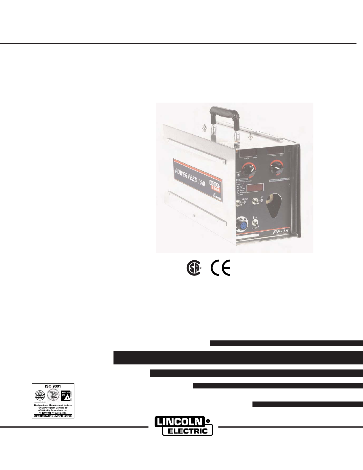
POWER FEED 15M
R
RETURN TO MAIN MENU
For use with machines having Code Number : 10940
Safety Depends on You
Lincoln arc welding and cutting
equipment is designed and built with
safety in mind. However, your overall
safety can be increased by proper
installation ... and thoughtful operation on your part. DO NOT
INSTALL, OPERATE OR REPAIR
THIS EQUIPMENT WITHOUT
READING THIS MANUAL AND
THE SAFETY PRECAUTIONS
CONTAINED THROUGHOUT. And,
most importantly, think before you
act and be careful.
IM761
September, 2005
Cleveland, Ohio 44117-1199 U.S.A. TEL: 216.481.8100 FAX: 216.486.1751 WEB SITE: www.lincolnelectric.com
NRTL/C
OPERATOR’S MANUAL
Copyright © 2005 Lincoln Global Inc.
• World's Leader in Welding and Cutting Products •
• Sales and Service through Subsidiaries and Distributors Worldwide •
Page 2

i
SAFETY
i
WARNING
CALIFORNIA PROPOSITION 65 WARNINGS
Diesel engine exhaust and some of its constituents
are known to the State of California to cause cancer, birth defects, and other reproductive harm.
The Above For Diesel Engines
ARC WELDING CAN BE HAZARDOUS. PROTECT YOURSELF AND OTHERS FROM POSSIBLE SERIOUS INJURY OR DEATH.
KEEP CHILDREN AWAY. PACEMAKER WEARERS SHOULD CONSULT WITH THEIR DOCTOR BEFORE OPERATING.
Read and understand the following safety highlights. For additional safety information, it is strongly recommended that you
purchase a copy of “Safety in Welding & Cutting - ANSI Standard Z49.1” from the American Welding Society, P.O. Box
351040, Miami, Florida 33135 or CSA Standard W117.2-1974. A Free copy of “Arc Welding Safety” booklet E205 is available
from the Lincoln Electric Company, 22801 St. Clair Avenue, Cleveland, Ohio 44117-1199.
BE SURE THAT ALL INSTALLATION, OPERATION, MAINTENANCE AND REPAIR PROCEDURES ARE
PERFORMED ONLY BY QUALIFIED INDIVIDUALS.
The engine exhaust from this product contains
chemicals known to the State of California to cause
cancer, birth defects, or other reproductive harm.
The Above For Gasoline Engines
FOR ENGINE
powered equipment.
1.a. Turn the engine off before troubleshooting and maintenance
work unless the maintenance work requires it to be running.
____________________________________________________
1.b. Operate engines in open, well-ventilated
areas or vent the engine exhaust fumes
outdoors.
____________________________________________________
1.c. Do not add the fuel near an open flame
welding arc or when the engine is running.
Stop the engine and allow it to cool before
refueling to prevent spilled fuel from vaporizing on contact with hot engine parts and
igniting. Do not spill fuel when filling tank. If
fuel is spilled, wipe it up and do not start
engine until fumes have been eliminated.
____________________________________________________
1.d. Keep all equipment safety guards, covers and devices in
position and in good repair.Keep hands, hair, clothing and
tools away from V-belts, gears, fans and all other moving
parts when starting, operating or repairing equipment.
____________________________________________________
1.e. In some cases it may be necessary to remove safety
guards to perform required maintenance. Remove
guards only when necessary and replace them when the
maintenance requiring their removal is complete.
Always use the greatest care when working near moving
parts.
___________________________________________________
1.f. Do not put your hands near the engine fan.
Do not attempt to override the governor or
idler by pushing on the throttle control rods
while the engine is running.
1.h. To avoid scalding, do not remove the
radiator pressure cap when the engine is
hot.
ELECTRIC AND
MAGNETIC FIELDS
may be dangerous
2.a. Electric current flowing through any conductor causes
localized Electric and Magnetic Fields (EMF). Welding
current creates EMF fields around welding cables and
welding machines
2.b. EMF fields may interfere with some pacemakers, and
welders having a pacemaker should consult their physician
before welding.
2.c. Exposure to EMF fields in welding may have other health
effects which are now not known.
2.d. All welders should use the following procedures in order to
minimize exposure to EMF fields from the welding circuit:
2.d.1.
Route the electrode and work cables together - Secure
them with tape when possible.
2.d.2. Never coil the electrode lead around your body.
2.d.3. Do not place your body between the electrode and
work cables. If the electrode cable is on your right
side, the work cable should also be on your right side.
___________________________________________________
1.g. To prevent accidentally starting gasoline engines while
turning the engine or welding generator during maintenance
work, disconnect the spark plug wires, distributor cap or
magneto wire as appropriate.
2.d.4. Connect the work cable to the workpiece as close as
possible to the area being welded.
2.d.5. Do not work next to welding power source.
Mar ‘95
Page 3

ii
SAFETY
ii
ELECTRIC SHOCK can
kill.
3.a. The electrode and work (or ground) circuits
are electrically “hot” when the welder is on.
Do not touch these “hot” parts with your bare
skin or wet clothing. Wear dry, hole-free
gloves to insulate hands.
3.b. Insulate yourself from work and ground using dry insulation.
Make certain the insulation is large enough to cover your full
area of physical contact with work and ground.
In addition to the normal safety precautions, if welding
must be performed under electrically hazardous
conditions (in damp locations or while wearing wet
clothing; on metal structures such as floors, gratings or
scaffolds; when in cramped positions such as sitting,
kneeling or lying, if there is a high risk of unavoidable or
accidental contact with the workpiece or ground) use
the following equipment:
• Semiautomatic DC Constant Voltage (Wire) Welder.
• DC Manual (Stick) Welder.
• AC Welder with Reduced Voltage Control.
3.c. In semiautomatic or automatic wire welding, the electrode,
electrode reel, welding head, nozzle or semiautomatic
welding gun are also electrically “hot”.
3.d. Always be sure the work cable makes a good electrical
connection with the metal being welded. The connection
should be as close as possible to the area being welded.
3.e. Ground the work or metal to be welded to a good electrical
(earth) ground.
ARC RAYS can burn.
4.a. Use a shield with the proper filter and cover
plates to protect your eyes from sparks and
the rays of the arc when welding or observing
open arc welding. Headshield and filter lens
should conform to ANSI Z87. I standards.
4.b. Use suitable clothing made from durable flame-resistant
material to protect your skin and that of your helpers from
the arc rays.
4.c. Protect other nearby personnel with suitable, non-flammable
screening and/or warn them not to watch the arc nor expose
themselves to the arc rays or to hot spatter or metal.
FUMES AND GASES
can be dangerous.
5.a. Welding may produce fumes and gases
hazardous to health. Avoid breathing these
fumes and gases.When welding, keep
your head out of the fume. Use enough
ventilation and/or exhaust at the arc to keep
fumes and gases away from the breathing zone. When
welding with electrodes which require special
ventilation such as stainless or hard facing (see
instructions on container or MSDS) or on lead or
cadmium plated steel and other metals or coatings
which produce highly toxic fumes, keep exposure as
low as possible and below Threshold Limit Values (TLV)
using local exhaust or mechanical ventilation. In
confined spaces or in some circumstances, outdoors, a
respirator may be required. Additional precautions are
also required when welding on galvanized steel.
3.f.
Maintain the electrode holder, work clamp, welding cable and
welding machine in good, safe operating condition. Replace
damaged insulation.
3.g. Never dip the electrode in water for cooling.
3.h. Never simultaneously touch electrically “hot” parts of
electrode holders connected to two welders because voltage
between the two can be the total of the open circuit voltage
of both welders.
3.i. When working above floor level, use a safety belt to protect
yourself from a fall should you get a shock.
3.j. Also see Items 6.c. and 8.
5.b.
Do not weld in locations near chlorinated hydrocarbon
coming from degreasing, cleaning or spraying operations.
The heat and rays of the arc can react with solvent vapors
form phosgene, a highly toxic gas, and other irritating products.
5.c. Shielding gases used for arc welding can displace air and
cause injury or death. Always use enough ventilation,
especially in confined areas, to insure breathing air is safe.
5.d. Read and understand the manufacturer’s instructions for this
equipment and the consumables to be used, including the
material safety data sheet (MSDS) and follow your
employer’s safety practices. MSDS forms are available from
your welding distributor or from the manufacturer.
5.e. Also see item 1.b.
vapors
Mar ‘95
to
Page 4
iii
SAFETY
iii
WELDING SPARKS can
cause fire or explosion.
6.a.
Remove fire hazards from the welding area.
If this is not possible, cover them to prevent
the welding sparks from starting a fire.
materials from welding can easily go through small cracks
and openings to adjacent areas. Avoid welding near
hydraulic lines. Have a fire extinguisher readily available.
6.b. Where compressed gases are to be used at the job site,
special precautions should be used to prevent hazardous
situations. Refer to “Safety in Welding and Cutting” (ANSI
Standard Z49.1) and the operating information for the
equipment being used.
6.c. When not welding, make certain no part of the electrode
circuit is touching the work or ground. Accidental contact
can cause overheating and create a fire hazard.
6.d. Do not heat, cut or weld tanks, drums or containers until the
proper steps have been taken to insure that such procedures
will not cause flammable or toxic vapors from substances
inside. They can cause an explosion even
been “cleaned”. For information, purchase “Recommended
Safe Practices for the
Containers and Piping That Have Held Hazardous
Substances”, AWS F4.1 from the American Welding Society
(see address above).
6.e. Vent hollow castings or containers before heating, cutting or
welding. They may explode.
Sparks and spatter are thrown from the welding arc. Wear oil
6.f.
free protective garments such as leather gloves, heavy shirt,
cuffless trousers, high shoes and a cap over your hair. Wear
ear plugs when welding out of position or in confined places.
Always wear safety glasses with side shields when in a
welding area.
6.g. Connect the work cable to the work as close to the welding
area as practical. Work cables connected to the building
framework or other locations away from the welding area
increase the possibility of the welding current passing
through lifting chains, crane cables or other alternate circuits. This can create fire hazards or overheat lifting chains
or cables until they fail.
6.h. Also see item 1.c.
Remember that welding sparks and hot
though
they have
Preparation
for Welding and Cutting of
CYLINDER may explode
if damaged.
7.a. Use only compressed gas cylinders
containing the correct shielding gas for the
process used and properly operating
regulators designed for the gas and
pressure used. All hoses, fittings, etc. should be suitable for
the application and maintained in good condition.
7.b. Always keep cylinders in an upright position securely
chained to an undercarriage or fixed support.
7.c. Cylinders should be located:
• Away from areas where they may be struck or subjected to
physical damage.
• A safe distance from arc welding or cutting operations and
any other source of heat, sparks, or flame.
7.d. Never allow the electrode, electrode holder or any other
electrically “hot” parts to touch a cylinder.
7.e. Keep your head and face away from the cylinder valve outlet
when opening the cylinder valve.
7.f. Valve protection caps should always be in place and hand
tight except when the cylinder is in use or connected for
use.
7.g. Read and follow the instructions on compressed gas
cylinders, associated equipment, and CGA publication P-l,
“Precautions for Safe Handling of Compressed Gases in
Cylinders,” available from the Compressed Gas Association
1235 Jefferson Davis Highway, Arlington, VA 22202.
FOR ELECTRICALLY
powered equipment.
8.a. Turn off input power using the disconnect
switch at the fuse box before working on
the equipment.
8.b. Install equipment in accordance with the U.S. National
Electrical Code, all local codes and the manufacturer’s
recommendations.
8.c. Ground the equipment in accordance with the U.S. National
Electrical Code and the manufacturer’s recommendations.
Mar ‘95
Page 5

iv
SAFETY
iv
PRÉCAUTIONS DE SÛRETÉ
Pour votre propre protection lire et observer toutes les instructions
et les précautions de sûreté specifiques qui parraissent dans ce
manuel aussi bien que les précautions de sûreté générales suivantes:
Sûreté Pour Soudage A L’Arc
1. Protegez-vous contre la secousse électrique:
a. Les circuits à l’électrode et à la piéce sont sous tension
quand la machine à souder est en marche. Eviter toujours
tout contact entre les parties sous tension et la peau nue
ou les vétements mouillés. Porter des gants secs et sans
trous pour isoler les mains.
b. Faire trés attention de bien s’isoler de la masse quand on
soude dans des endroits humides, ou sur un plancher
metallique ou des grilles metalliques, principalement dans
les positions assis ou couché pour lesquelles une grande
partie du corps peut être en contact avec la masse.
c. Maintenir le porte-électrode, la pince de masse, le câble
de soudage et la machine à souder en bon et sûr état
defonctionnement.
d.Ne jamais plonger le porte-électrode dans l’eau pour le
refroidir.
e. Ne jamais toucher simultanément les parties sous tension
des porte-électrodes connectés à deux machines à souder
parce que la tension entre les deux pinces peut être le
total de la tension à vide des deux machines.
f. Si on utilise la machine à souder comme une source de
courant pour soudage semi-automatique, ces precautions
pour le porte-électrode s’applicuent aussi au pistolet de
soudage.
2. Dans le cas de travail au dessus du niveau du sol, se protéger
contre les chutes dans le cas ou on recoit un choc. Ne jamais
enrouler le câble-électrode autour de n’importe quelle partie
du corps.
5. Toujours porter des lunettes de sécurité dans la zone de
soudage. Utiliser des lunettes avec écrans lateraux dans les
zones où l’on pique le laitier.
6. Eloigner les matériaux inflammables ou les recouvrir afin de
prévenir tout risque d’incendie dû aux étincelles.
7. Quand on ne soude pas, poser la pince à une endroit isolé de
la masse. Un court-circuit accidental peut provoquer un
échauffement et un risque d’incendie.
8. S’assurer que la masse est connectée le plus prés possible
de la zone de travail qu’il est pratique de le faire. Si on place
la masse sur la charpente de la construction ou d’autres
endroits éloignés de la zone de travail, on augmente le risque
de voir passer le courant de soudage par les chaines de levage, câbles de grue, ou autres circuits. Cela peut provoquer
des risques d’incendie ou d’echauffement des chaines et des
câbles jusqu’à ce qu’ils se rompent.
9. Assurer une ventilation suffisante dans la zone de soudage.
Ceci est particuliérement important pour le soudage de tôles
galvanisées plombées, ou cadmiées ou tout autre métal qui
produit des fumeés toxiques.
10. Ne pas souder en présence de vapeurs de chlore provenant
d’opérations de dégraissage, nettoyage ou pistolage. La
chaleur ou les rayons de l’arc peuvent réagir avec les vapeurs
du solvant pour produire du phosgéne (gas fortement toxique)
ou autres produits irritants.
11. Pour obtenir de plus amples renseignements sur la sûreté,
voir le code “Code for safety in welding and cutting” CSA
Standard W 117.2-1974.
PRÉCAUTIONS DE SÛRETÉ POUR
3. Un coup d’arc peut être plus sévère qu’un coup de soliel,
donc:
a. Utiliser un bon masque avec un verre filtrant approprié
ainsi qu’un verre blanc afin de se protéger les yeux du rayonnement de l’arc et des projections quand on soude ou
quand on regarde l’arc.
b. Porter des vêtements convenables afin de protéger la
peau de soudeur et des aides contre le rayonnement de
l‘arc.
c. Protéger l’autre personnel travaillant à proximité au
soudage à l’aide d’écrans appropriés et non-inflammables.
4. Des gouttes de laitier en fusion sont émises de l’arc de
soudage. Se protéger avec des vêtements de protection libres
de l’huile, tels que les gants en cuir, chemise épaisse, pantalons sans revers, et chaussures montantes.
LES MACHINES À SOUDER À
TRANSFORMATEUR ET À
REDRESSEUR
1. Relier à la terre le chassis du poste conformement au code de
l’électricité et aux recommendations du fabricant. Le dispositif
de montage ou la piece à souder doit être branché à une
bonne mise à la terre.
2. Autant que possible, I’installation et l’entretien du poste seront
effectués par un électricien qualifié.
3. Avant de faires des travaux à l’interieur de poste, la debrancher à l’interrupteur à la boite de fusibles.
4. Garder tous les couvercles et dispositifs de sûreté à leur
place.
Mar. ‘93
Page 6
for selecting a QUALITY product by Lincoln Electric. We want you
Thank You
to take pride in operating this Lincoln Electric Company product
••• as much pride as we have in bringing this product to you!
Please Examine Carton and Equipment For Damage Immediately
When this equipment is shipped, title passes to the purchaser upon receipt by the carrier. Consequently, Claims
for material damaged in shipment must be made by the purchaser against the transportation company at the
time the shipment is received.
Please record your equipment identification information below for future reference. This information can be
found on your machine nameplate.
Product _________________________________________________________________________________
Model Number ___________________________________________________________________________
Code Number or Date Code_________________________________________________________________
Serial Number____________________________________________________________________________
Date Purchased___________________________________________________________________________
Where Purchased_________________________________________________________________________
vv
Whenever you request replacement parts or information on this equipment, always supply the information you
have recorded above. The code number is especially important when identifying the correct replacement parts.
On-Line Product Registration
- Register your machine with Lincoln Electric either via fax or over the Internet.
• For faxing: Complete the form on the back of the warranty statement included in the literature packet
accompanying this machine and fax the form per the instructions printed on it.
• For On-Line Registration: Go to our
“Product Registration”. Please complete the form and submit your registration.
Read this Operators Manual completely before attempting to use this equipment. Save this manual and keep it
handy for quick reference. Pay particular attention to the safety instructions we have provided for your protection.
The level of seriousness to be applied to each is explained below:
WEB SITE at www.lincolnelectric.com. Choose “Quick Links” and then
WARNING
This statement appears where the information must be followed exactly to avoid serious personal injury or
loss of life.
CAUTION
This statement appears where the information must be followed to avoid minor personal injury or damage to
this equipment.
Page 7

vi
TABLE OF CONTENTS
Page
Installation.......................................................................................................................Section A
Technical Specifications.......................................................................................................A-1
Safety Precautions ...............................................................................................................A-2
Location................................................................................................................................A-2
High Frequency Protection...................................................................................................A-2
Digital Welding System Components ...................................................................................A-2
Control Cable Connection ....................................................................................................A-3
Weld Cable Size and Table..................................................................................................A-3
Coaxial Weld Cable..............................................................................................................A-4
Electrode Polarity .................................................................................................................A-4
Shielding Gas Connection....................................................................................................A-4
Changing The Drive Motor Gears ........................................................................................A-5
Wire Drive Configuration ......................................................................................................A-6
Procedure to Install Drive Rolls and Wire Guides ................................................................A-6
Remote Sense Lead Specification .......................................................................................A-7
________________________________________________________________________________
Operation.........................................................................................................................Section B
Safety Precautions ...............................................................................................................B-1
Graphic Symbols that appear on this Machine or in this Manual .........................................B-1
Definition of Welding Terms .................................................................................................B-2
General Description..............................................................................................................B-3
Duty Cycle ............................................................................................................................B-3
Recommended Processes ...................................................................................................B-3
Processes Limitations ..........................................................................................................B-3
Equipment Limitations ..........................................................................................................B-3
Making a Weld with Waveform Technology Power Sources................................................B-4
General Welding Adjustments..............................................................................................B-4
1. WFS/AMPS ...............................................................................................................B-4
2. Volts/Trim ..................................................................................................................B-4
3. Welding Mode ...........................................................................................................B-4
4. Arc Control ................................................................................................................B-4
Constant Voltage (CV) Welding ...........................................................................................B-5
Pulse Welding ......................................................................................................................B-5
STT Synergic Welding..........................................................................................................B-6
Case Front Controls .............................................................................................B-7 thru B-10
Extended Features Menu ...................................................................................................B-11
Internal Controls .................................................................................................................B-12
Cold Feed/Gas Purge Switch......................................................................................B-12
Idle Roll Pressure Setting............................................................................................B-12
Flow Meter..........................................................................................................................B-13
2 Step - 4 Step Trigger Operation and Graphics ................................................B-14 thru B-18
________________________________________________________________________________
Accessories ....................................................................................................................Section C
Factory Installed Equipment.................................................................................................C-1
Drive Roll Kits used..............................................................................................................C-1
Common Packages with Accessories Used.........................................................................C-1
________________________________________________________________________________
Maintenance....................................................................................................................Section D
Safety Precautions ...............................................................................................................D-1
Routine Maintenance ...........................................................................................................D-1
Periodic Maintenance...........................................................................................................D-1
Calibration Specification.......................................................................................................D-1
________________________________________________________________________________
Troubleshooting .............................................................................................................Section E
How to Use Troubleshooting Guide .....................................................................................E-1
Error Fault Codes ..........................................................................................................E-2,E-3
Troubleshooting Guide ...........................................................................................E-4 thru E-5
________________________________________________________________________________
vi
Wiring Diagram & Dimension Prints .............................................................................Section F
________________________________________________________________________________
Parts Pages .............................................................................................................................P484
_______________________________________________________________________
________
Page 8
A-1
INSTALLATION
A-1
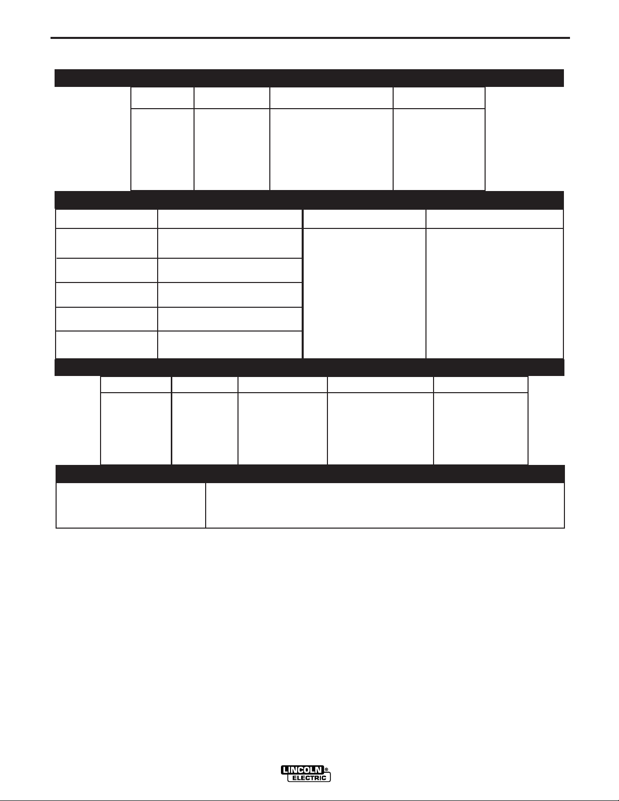
TECHNICAL SPECIFICATIONS –
INPUT VOLTAGE and CURRENT
MODEL
K2196-1
Domestic
DUTY CYCLE
35% rating
60% rating
100% rating
ELECTRODE DIAMETERS and SPEED RANGE
PROCESS
GMAW
GMAW-Pulsed
GMAW-STT
FCAW
FCAW- Gas Shielded
ELECTRODE DIAMETER RANGE
.023 - .052"
(0.6 -1.3 mm)
.023 - .052"
(0.6 -1.3 mm)
.023 - .052"
(0.6 -1.3 mm)
0.035 - 5/64"
(0.9mm - 2.0 mm)
0.035 - 5/64"
(0.9mm - 2.0 mm)
POWER FEED 15M K2196-1
INPUT VOLTAGE ± 10%
40 VDC
OUTPUT RANGE (AMPERES)
up to 500 Amps
INPUT AMPERES
5A
WIRE FEED SPEED RANGE
50 - 700 ipm (1.3 - 17.8
m/min)
PHYSICAL DIMENSIONS
MODEL
K2196-1
Domestic
HEIGHT WIDTH DEPTH WEIGHT
12 Inches 9 Inches 23.3 Inches 34 lbs
(305 mm) ( 229 mm) (590 mm) (15.5 kg)
TEMPERATURE RANGE
OPERATION: -14° F to 140° F (- 10° C to 60oC)
STORAGE: - 40° F to 185° F (- 40° C to 85oC)
POWER FEED 15M
Page 9

A-2
Digital Control Cable
Work
Cable
Electrode Cable
Power Sou rc e
Wire Feeder
+
-
Welding Gun
Shielding
Gas Hose
Shielding
Gas Hose
Digital Control Cable
Work
Connection
Coaxial Weld Cable
Power Sourc e
Wire Feeder
+
-
Welding Gun
SAFETY PRECAUTIONS
INSTALLATION
HIGH FREQUENCY PROTECTION
A-2
WARNING
ELECTRIC SHOCK CAN KILL.
• ONLY QUALIFIED PERSONNEL
SHOULD PERFORM THIS
INSTALLATION.
• Turn off input power to the power
source at the disconnect switch or
fuse box before working on this
equipment. Turn off the input power to any other
equipment connected to the welding system at
the disconnect switch or fuse box before
working on the equipment.
• Do not touch electrically hot parts.
-------------------------------------------------------------------
LOCATION
The Power Feed 15M has an IP23 rating, suitable for
outdoor use.
The Power Feed 15M should be positioned upright on
a horizontal surface. Do not submerge the Power
Feed 15M in water. The best practice is to keep the
wire feeder in a dry environment. When working
outdoors in severe wet weather, place the Power Feed
15M with the door facing up.
CAUTION
Locate the Power Feed 15M away from radio controlled machinery. The normal operation of the
Power Feed 15M may adversely affect the operation
of RF controlled equipment, which may result in
bodily injury or damage to the equipment.
----------------------------------------------------------------------------
CONNECTION DIAGRAMS
CV Welding: Figure A.1
Pulse Welding or STT Welding: Figure A.2
POWER FEED 15M
Page 10
A-3
Po
wer
Source
A
B
C
D
E
W
ireFeeder
A
B
C
D
E
A
B
C
D
E
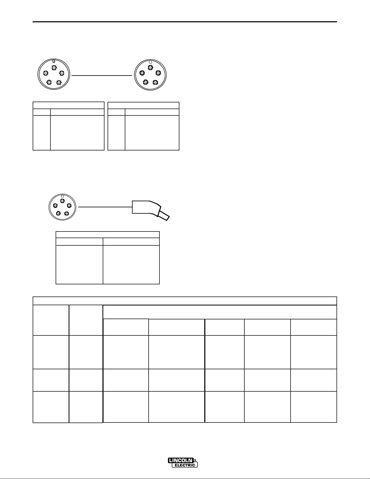
CONTROL CABLE CONNECTION:
INSTALLATION
WELD CABLE SIZE
A-3
Digital Control Cable: Figure A.3
Power Source
Pin Function
A Digital I/O
B Digital I/O
C "67" voltage sense
D 40 VDC
E 40 VDC
Wire Feeder
Pin Function
A Digital I/O
B Digital I/O
C "67" voltage sense
D 40 VDC
E 40 VDC
Welding Gun/Wire Feeder Trigger Connector
Wire Feeder: Figure A.4
Wire Feede r
n
i
g Gun
Weld
Table A.1 located below are copper cable sizes recommended for different currents and duty cycles.
Lengths stipulated are the distance from the welder to
work and back to the welder again. Cable sizes are
increased for greater lengths primarily for the purpose
of minimizing cable drop.
WIRE FEEDER
Pin Function
A Gun Trigger
B C Common
D Dual Procedure
E Common
TABLE A.1
RECOMMENDED CABLE SIZES (RUBBER COVERED COPPER - RATED 167°F or 75°C)**
CABLE SIZES FOR COMBINED LENGTHS OF ELECTRODE AND WORK CABLES
AMPRERES
200
200
225
225
250
250
250
250
300
325
350
400
400
500
** Tabled values are for operation at ambient temperatures of 104°F(40°C) and below. Applications above 104°F(40°C) may require cables
larger than recommended, or cables rated higher than 167°F(75°C).
PERCENT
DUTY
CYCLE
60
100
20
40 & 30
30
40
60
100
60
100
60
60
100
60
0 to 50Ft.
(0 to15M)
2
2
4 or 5
3
3
2
1
1
1
2/0
1/0
2/0
3/0
2/0
50 to 100Ft.
(15 to 30M)
2
2
3
3
3
2
1
1
1
2/0
1/0
2/0
3/0
2/0
POWER FEED 15M
100 to 150 Ft.
(30 to 46M)
2
2
2
2
2
1
1
1
1
2/0
2/0
2/0
3/0
3/0
150 to 200 Ft.
(46 to 61M)
1
1
1
1
1
1
1
1
1/0
2/0
2/0
3/0
3/0
3/0
200 to 250 Ft.
(61 to 76M)
1/0
1/0
1/0
1/0
1/0
1/0
1/0
1/0
2/0
3/0
3/0
4/0
4/0
4/0
Page 11
A-4
Electrode
Work
Work
ElectrodeElectrode
WWorkork
ElectrodeElectrode
W
Workork
Power SourcePower Source
Coaxial WCoaxial Weld Cableeld Cable
Wire FeederWire Feeder
INSTALLATION
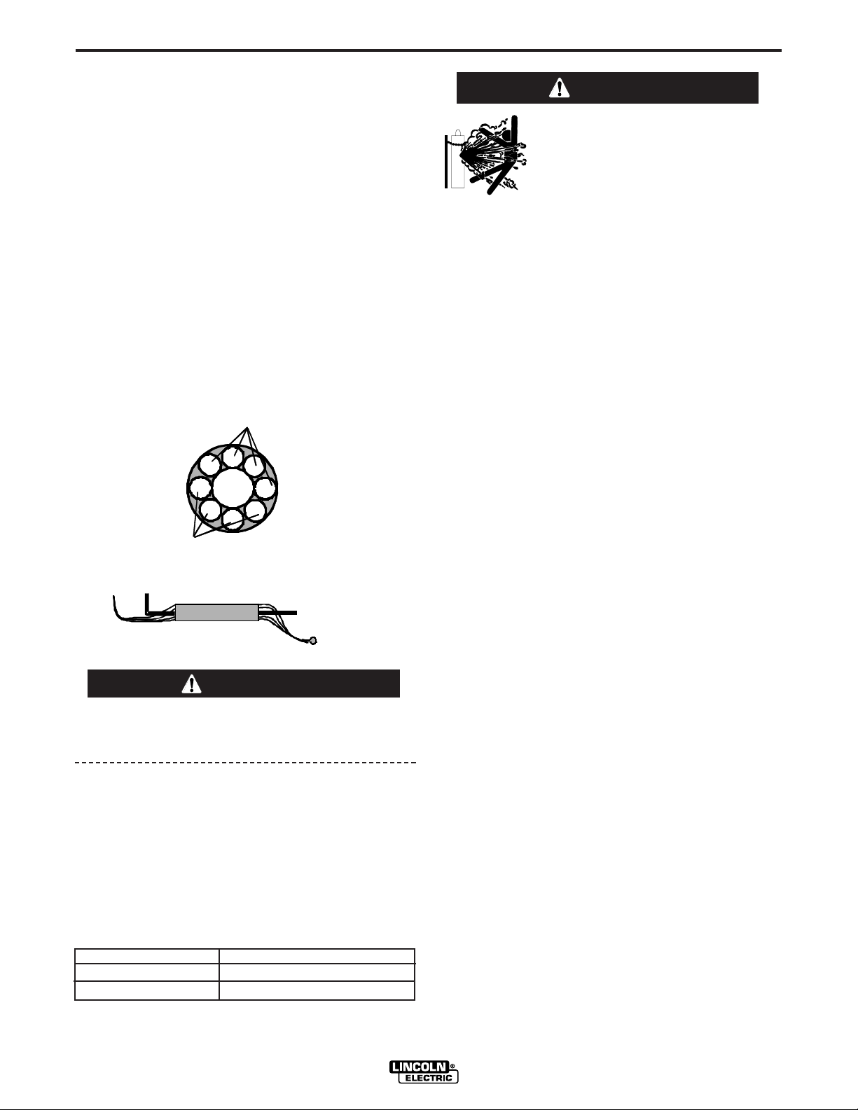
COAXIAL WELD CABLE
Coaxial welding cables are specially designed welding
cables for pulse welding or STT welding. Coaxial weld
cables feature low inductance, allowing fast changes in the
weld current. Regular cables have a higher inductance
which may distort the pulse or STT waveshape. Inductance
becomes more severe as the weld cables become longer.
A-4
SHIELDING GAS CONNECTION
WARNING
CYLINDER may explode if
damaged.
• Keep cylinder upright and
chained to support.
Coaxial weld cables are recommended for all pulse and STT
welding, especially when the total weld cable length (electrode cable + work cable) exceeds 50 feet (7.6m)
• Keep cylinder away from areas where it may be
damaged.
• Never lift welder with cylinder attached.
• Never allow welding electrode to touch cylinder.
A coaxial weld cable is constructed by 8 small leads
wrapped around one large lead. The large inner lead connects to the electrode stud on the power source and the
electrode connection on the wire feeder. The small leads
combine together to form the work lead, one end attached to
the power source and the other end to the work piece. See
Figure A.5
FIGURE A.5
• Keep cylinder away from welding or other live
electrical circuits.
• BUILD UP OF SHIELDING GAS MAY HARM
HEALTH OR KILL.
• Shut off shielding gas supply when not in use.
• See American National Standard Z-49.1, "Safety
in Welding and Cutting” Published by the
American Welding Society.
------------------------------------------------------------------------
Install the shielding gas supply as follows:
1. Secure the cylinder to prevent it from falling.
2. Remove the cylinder cap. Inspect the cylinder valves and
regulator for damaged threads, dirt, dust, oil or grease.
Remove dust and dirt with a clean cloth. DO NOT
ATTACH THE REGULATOR IF OIL, GREASE OR DAMAGE IS PRESENT! Inform your gas supplier of this con-
dition. Oil or grease in the presence of high pressure oxygen is explosive.
3. Stand to one side away from the outlet and open the
cylinder valve for an instant. This blows away any dust or
dirt which may have accumulated in the valve outlet.
ELECTRODE POLARITY
CAUTION
When changing the electrode polarity, the weld cables must be
changed at the power source studs and the DIP switch inside the
Power Feed 15M must be properly set. Operation with the DIP
switch in the wrong position will cause erratic arc performance.
The Power Feed 15M is factory set for Electrode Positive welding. Most welding procedures use Electrode Positive welding.
Some Innershield procedures may use Electrode Negative
welding.
To change the DIP switch iside the Power Feed 15M electrode
polarity:
1. Turn off power at the welding power source.
2. Remove the rear access panel on the wire drive.
3. Locate DIP switches on the Wire Drive Board.
4. Set DIP switch #7 to the desired polarity.
DIP Switch #7 Position Polarity
4. Attach the flow regulator to the cylinder valve and tighten
the union nut(s) securely with a wrench. Note: if connecting to 100% CO2 cylinder, insert regulator adapter
between regulator and cylinder valve. If adapter is
equipped with a plastic washer, be sure it is seated for
connection to the CO2 cylinder.
5. Attach one end of the inlet hose to the outlet fitting of the
flow regulator. Attach the other end to the welding system
shielding gas inlet. Tighten the union nuts with a wrench.
6. Before opening the cylinder valve, turn the regulator
adjusting knob counterclockwise until the adjusting spring
pressure is released.
7. Standing to one side, open the cylinder valve slowly a
fraction of a turn. When the cylinder pressure gage stops
moving, open the valve fully.
8. The flow regulator is adjustable. Adjust it to the flow rate
recommended for the procedure and process being used
before making a weld.
ON (Up) - (negative) polarity
OFF (Down) + (positive) polarity
5. Assemble the rear access panel to the wire drive.
6. Restore power.
POWER FEED 15M
Page 12
A-5
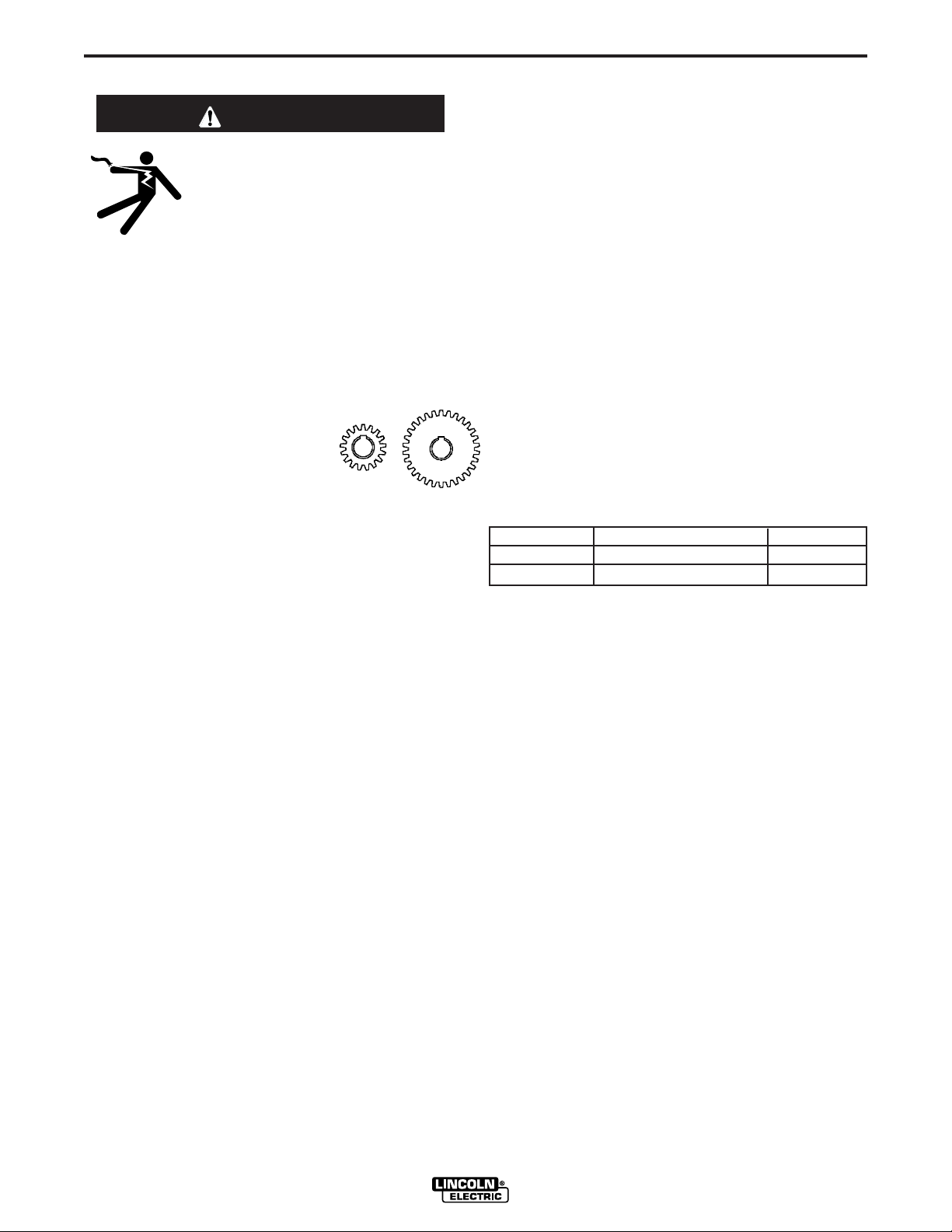
Low Speed
High T orque
Gear
High Speed
Low T orque
Gear
INSTALLATION
CHANGING THE DRIVE MOTOR GEAR RATIO
WARNING
A-5
11. Use a 5/16" nut driver to remove the four screws
and washers holding the insulated panel to the
sheet metal bracket.
• Turn off input power at the welding power source before installation or changing drive roll and/or
wire guides.
• Do not touch electrically live parts
such as the wire drive or internal
wiring.
• When feeding with the gun trigger, the electrode
and wire drive mechanism are "hot" to work and
ground and could remain energized several seconds after the gun trigger is released.
• Only qualified personnel should perform this
operation.
------------------------------------------------------------------------
Tools required:
• 1/4" hex key wrench
• 3/4" socket and ratchet wrench
• 9/16" socket and ratchet wrench
• 7/16" nut driver
• 5/16" nut driver
• Phillips screw driver
1. Remove the spool of electrode from the wire feeder.
2. Loosen the thumb screw at the wire drive and remove the
welding gun. Take the tension off the drive rollers and
open the tension handle.
12. Lift the wire drive assembly partially out of the wire
feeder. With a Phillips screw driver, remove the
three screws and lock washers securing the
motor. Remove the motor.
13. Place the motor in the new position.
14. Assemble the three screws and lock washers
holding the wire drive motor.
15. Place the wire drive assembly inside the wire
feeder. With a 5/16" nut driver, assemble the four
screws and lock washers to hold the insulating
panel to the sheet metal bracket.
16. With a 7/16" nut driver, replace the bolt at the top
securing the wire drive insulated panel to the
sheet metal case.
17) Move DIP switch #8 on the Feed head board to
the appropriate position.
Gear Select DIP Switch #8 Setting Range
High Speed ON 50 – 700 ipm
Low Speed OFF 50 – 400 ipm
18. Reassemble the cover assembly protecting the
display board with a 5/16" nut driver.
3. Remove the outer wire guide, drive rolls and inner wire
guide.
4. Use a 7/16" nut driver to remove the gear cover.
5. Use 9/16" socket and ratchet wrench to remove the lower
drive roll hub retainer. Remove the lower drive roll hub.
6. With a Phillips screwdriver, remove the screw, washer
and collar holding the pinion gear. Remove the pinion
gear.
7. Remove the electrode lead by unscrewing the bolt using
a 3/4" socket and ratchet wrench.
8. With a 1/4" hex key wrench, loosen the socket head cap
screw securing the gun bushing. Remove the gun bushing from the wire drive.
9. With a 5/16" nut driver remove the screws securing the
cover assembly protecting the display board. Lift out the
cover assembly enough so it does not overlap the wire
drive.
10. Use a 7/16" nut driver to remove the bolt at the top
securing the wire drive insulated panel to the sheet
metal case.
POWER FEED 15M
19. Place the gun bushing in the wire drive and align
the threaded hole in the gun bushing with the hole
in the feed plate. With a 1/4" hex key, tighten the
socket head cap screw to secure the bushing in
the wire drive.
20. Reassemble the electrode and tighten the mounting hardware with a 3/4" socket and ratchet
wrench.
21. Place the new gear on the motor shaft. Secure the
gear to the motor shaft with the collar, washer and
screw.
22. Reassemble the lower drive roll hub and lower
drive roll hub retainer.
23. Reassemble the gear cover.
24. Reassemble the inner wire guide, drive rolls and
outer wire guide.
25. Place the welding gun into the gun bushing and
secure with the thumb screw.
Page 13

A-6
G
E
WIRE DRIVE CONFIGURATION
(See Figure A-6)
Changing the Gun Receiver Bushing
INSTALLATION
10. Tighten the socket head cap screw.
11. Insert the welding gun into the gun bushing and
tighten the thumb screw.
A-6
WARNING
ELECTRIC SHOCK can kill.
• Turn the input power OFF at the
welding power source before installation or changing drive rolls and/or
guides.
• Do not touch electrically live parts.
• When inching with the gun trigger, electrode
and drive mechanism are "hot" to work and
ground and could remain energized several seconds after the gun trigger is released.
• Only qualified personnel should perform maintenance work.
------------------------------------------------------------------------
Tools required:
• 1/4" hex key wrench.
Note: Some gun bushings do not require the use of
the thumb screw.
1. Turn power off at the welding power source.
2. Remove the welding wire from the wire drive.
3. Remove the thumb screw from the wire drive.
4. Remove the welding gun from the wire drive.
5. Loosen the socket head cap screw that holds the
connector bar against the gun bushing.
Important: Do not attempt to completely
remove the socket head cap screw.
6. Remove the outer wire guide, and push the gun
bushing out of the wire drive. Because of the precision fit, light tapping may be required to remove
the gun bushing.
7. Disconnect the shielding gas hose from the gun
bushing, if required.
8. Connect the shielding gas hose to the new gun
bushing, if required.
9. Rotate the gun bushing until the thumb screw hole
aligns with the thumb screw hole in the feed plate.
Slide the gun receiver bushing into the wire drive
and verify the thumb screw holes are aligned.
FIGURE A-6
THUMB SCREW
UN RECEIVER BUSHING
OUTER WIRE GUID
PROCEDURE TO INSTALL DRIVE ROLLS
AND WIRE GUIDES
WARNING
• Turn off input power at the welding power source
before installation or changing drive roll and/or
wire guides.
• Do not touch electrically live parts such as the
wire drive or internal wiring.
• When feeding with the gun trigger, the electrode
and wire drive mechanism are "hot" to work and
ground and could remain energized several seconds after the gun trigger is released.
• Only qualified personnel should perform this
operation.
------------------------------------------------------------------------
1. Release the idle roll pressure arm.
2. Remove the outer wire guide by turning the knurled
thumbscrews counter-clockwise to unscrew them
from the feed plate.
3. Rotate the triangular shaped drive roll retaining
mechanism to unlock the drive rolls and remove the
drive rolls.
4. Remove the inner wire guide.
5. Insert the new inner wire guide, groove side out,
over the two locating pins in the feed plate.
6. Install a drive roll on each hub assembly and lock
by rotating the triangular drive roll retaining mechanism.
7. Install the outer wire guide by aligning it with the
pins and tightening the knurled thumbscrews.
8. Close the idle arm and engage the idle roll pressure
arm. Adjust the pressure appropriately.
CONNECTOR BLOCK
SOCKET HEAD
CAP SCREW
LOOSEN TIGHTEN
POWER FEED 15M
Page 14
A-7
CONNECT A LL SENSE
LEADS AT THE END
OF THE WELD
CONNECT A
LL
WORK LEAD
S AT
THE BEGINN
ING
OF
THE WELD
DIRE
CTION
OF
TRAVEL
INSTALLATION
REMOTE SENSE LEAD SPECIFICATIONS
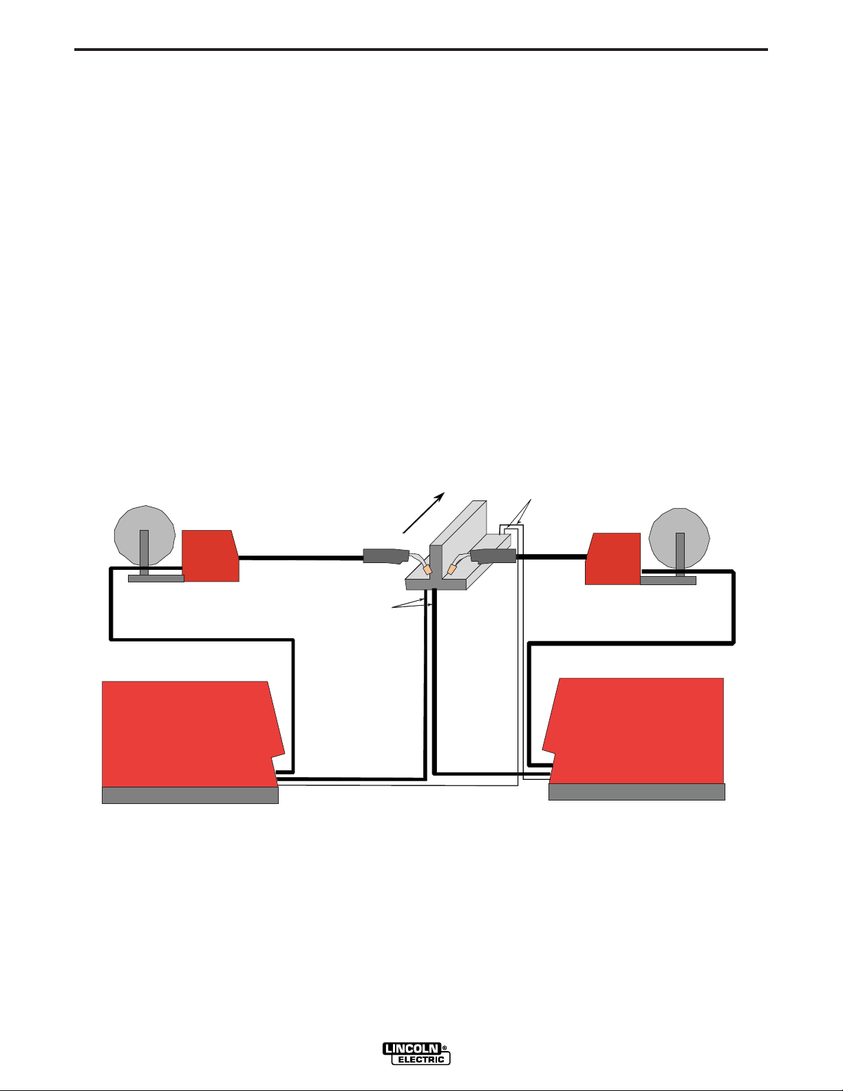
Welding with Multiple Arcs:
( See Figure A.7)
Special care must be taken when more than one arc
is welding simultaneously on a single part. Arc blow
and arc interference may occur or be magnified. Each
power source requires a work lead from the work stud
to the welding fixture. Do not combine all of the work
leads into one lead. Performing welding in the direction away from the work leads. Connect all of the work
sense leads from each power source to the work
piece at the end of the weld, such that they are out of
the path of the weld current. See Figure A.7
For the best results when pulse welding, set the wire
size and wire feed speed the same for all the arcs.
When these parameters are identical, the pulsing frequency will be the same, helping to stabilize the arcs.
FIGURE A.7
A-7
POWER FEED 15M
Page 15
B-1
OPERATION
B-1
SAFETY PRECAUTIONS
READ AND UNDERSTAND ENTIRE SECTION
BEFORE OPERATING MACHINE.
WARNING
• ELECTRIC SHOCK CAN KILL.
Unless using COLD FEED feature, when feeding with gun trigger, the electrode and drive
mechanism are always electrically energized and could
remain energized several seconds after the welding ceases..
• Do not touch electrically live part or electrode
with skin or wet clothing.
• Insulate yourself from work and ground.
• Always wear dry insulating gloves.
---------------------------------------------------------------------
• FUMES AND GASSES can be
dangerous.
• Keep your head out of fumes.
• Use ventilation or exhaust to
remove fumes from breathing
zone.
---------------------------------------------------------------------
• WELDING SPARKS can cause
fire or explosion.
• Keep flammable material away.
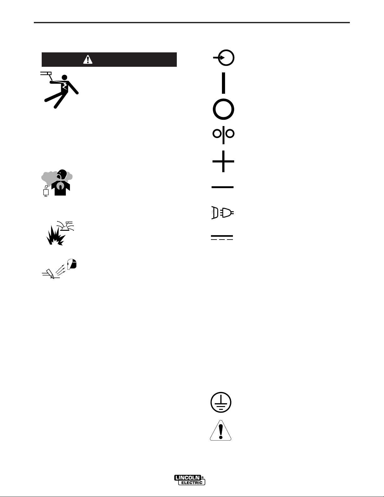
GRAPHIC SYMBOLS THAT APPEAR ON
THIS MACHINE OR IN THIS MANUAL
INPUT POWER
ON
OFF
WIRE FEEDER
POSITIVE OUTPUT
NEGATIVE OUTPUT
INPUT POWER
DIRECT CURRENT
---------------------------------------------------------------------ARC RAYS can burn.
• Wear eye, ear and body protection.
---------------------------------------------------------------------
SEE ADDITIONAL WARNING INFORMATION
UNDER ARC WELDING SAFETY PRECAUTIONS
AND IN THE FRONT OF THIS OPERATING MANUAL.
----------------------------------------------------------------------
U
U
U
I
I
0
1
2
1
2
OPEN CIRCUIT
VOLTAGE
INPUT VOLTAGE
OUTPUT VOLTAGE
INPUT CURRENT
OUTPUT CURRENT
PROTECTIVE
GROUND
WARNING OR
CAUTION
POWER FEED 15M
Page 16

B-2
OPERATION
B-2
DEFINITION OF WELDING TERMS
NON-SYNERGIC WELDING MODES
• A Non-synergic welding mode requires all welding
process variables to be set by the operator.
SYNERGIC WELDING MODES
• A Synergic welding mode offers the simplicity of
single knob control. The machine will select the correct voltage and amperage based on the wire feed
speed (WFS) set by the operator.
WFS
• Wire Feed Speed
CC
• Constant Current
CV
• Constant Voltage
GMAW
• Gas Metal Arc welding
GMAW-STT
• Gas Metal Arc welding-(Surface Tension Transfer)
SMAW
• Shielded Metal Arc welding
FCAW
• Flux Core Arc Welding
CAC
• Carbon Arc Cutting
CAG
• Carbon Arc Gouging
GMAW-P
• Gas Metal Arc welding-(Pulse Arc)
POWER FEED 15M
Page 17

B-3
OPERATION
GENERAL DESCRIPTION
The Power Feed 15M is a portable wire feeder for
customers seeking high end arc performance all
packed in a rugged stainless steel case. The stainless
steel case provides protection from corrosion, heat
and rough handling. The heart of the Power Feed15M is a rugged two roll, two speed wire drive capable
of driving electrode under the most demanding conditions. Shielding gas flow is easily regulated with a
built-in, standard flow meter that includes a flow control valve.
The Power Feed 15M runs with the Power Wave
power sources. "Dual boot" software programmed into
the Power Feed 15M operates with both ArcLink and
LincNet Power Waves. Customers may transport the
feeder between one vintage of power source and the
other without having to set any special switches.
A Mode Select Panel-3 type panel is permanently
mounted to the case front of the Power Feed 15M.
The panel allows the operator to customize many
weld parameters, including preflow and postflow
times, start and crater procedures, burnback, and
many more.
B-3
RECOMMENDED PROCESSES
The Power Feed 15M is best suited for alloy electrodes, out-of-position work, root welding and general
fabrication.
• GMAW
• GMAW-Pulse
• GMAW-STT
• FCAW
• SMAW
PROCESS LIMITATIONS
The Power Feed 15M is not suitable for:
• SAW
• CAG
• GTAW
EQUIPMENT LIMITATIONS
• The Power Feed 15M does not operate with the
Power Wave 450.
• The Power Feed 15M does not operate with any
analog based power sources (CV-xxx machines,
DC-xxx machines, etc.)
• Electrode spool size must not exceed 8" diameter.
• K435 spindle adapters ("pie pans") for Innershield
electrode do not fit in the Power Feed 15M.
An ON/OFF switch on the case front controls power to
the feeder.
DUTY CYCLE
The Power Feed 15M is rated for 500 amps, 60% duty
cycle and 350 amps, 100% duty. The duty cycle is
based on a 10 minute cycle.
For example, when welding at 500 amps, the Power
Feed 15M may run continuously for 6 minutes and
then must be shut off for 4 minutes.
POWER FEED 15M
Page 18

B-4
OPERATION
MAKING A WELD WITH WAVEFORM
TECHNOLOGY POWER SOURCES
B-4
GENERAL WELDING ADJUSTMENTS
1. WFS / AMPS:
WARNING
The serviceability of a product or structure utilizing
the welding programs is and must be the sole
responsibility of the builder/user. Many variables
beyond the control of The Lincoln Electric Company
affect the results obtained in applying these programs. These variables include, but are not limited
to, welding procedure, plate chemistry and temperature, weldment design, fabrication methods and service requirements. The available range of a welding
program may not be suitable for all applications, and
the build/user is and must be solely responsible for
welding program selection.
----------------------------------------------------------------------------
The steps for operating the Power Wave will vary
depending upon the user interface of the welding system. The flexibility of the Power Wave lets the user
customize operation for the best performance.
First, consider the desired welding process and the
part to be welded. Choose an electrode material,
diameter, shielding gas and process (GMAW, GMAWP, GMAW-STT, etc.)
Second, find the program in the welding software that
best matches the desired welding process. The standard software shipped with the Power Waves encompasses a wide range of common processes and will
meet most needs. If a special welding program is
desired, contact the local Lincoln Electric sales representative.
All adjustments are made on the user interface.
Because of the different configuration options your
system may not have all of the following adjustments.
Regardless of availability, all controls are described
below.
In synergic welding modes (synergic CV, pulse
GMAW, STT or power mode) WFS (wire feed speed)
is the dominant control parameter, controlling all other
variables. The user adjusts WFS according to factors
such as weld size, penetration requirements, heat
input, etc. The power source then uses the WFS setting to adjust its output characteristics (output voltage,
output current) according to pre-programmed settings.
In non-synergic modes, the WFS control behaves
more like a conventional CV power source where
WFS and voltage are independent adjustments.
Therefore to maintain the arc characteristics, the operator must adjust the voltage to compensate for any
changes made to the WFS.
2. VOLTS / TRIM:
In constant voltage modes (synergic CV, standard
CV) the control adjusts the welding voltage.
In pulse synergic welding modes (pulse GMAW only)
the user can change the Trim setting to adjust the arc
length. It is adjustable from 0.500 to 1.500. A Trim setting of 1.000 is a good starting point for most conditions.
In STT modes, the user can adjust the Trim setting to
change the overall heat input to the weld.
3. WELDING MODE:
May be selected by name (CV/MIG, CC/Stick Crisp,
Gouge, etc.) or by a mode number (10, 24, 71, etc.).
Selecting a welding mode determines the output characteristics of the power source.
4. ARC CONTROL:
Also known as Inductance or wave control. Allows
operator to vary the arc characteristics from "soft" to
"harsh" in all weld modes. It is adjustable from -10.0 to
+10.0, with a nominal setting of 0.0. Also varies inductance in CV, in pulse modes, changes pulsing frequency and background current.
POWER FEED 15M
Page 19

B-5
Arc
Arc Control 0.00
Control +10.
0
Wave Control -10.0
Current
Amps
Amps
TTime
ime
CC
Arc
ontrol 0.0
C
Arc
ontrol +10.0
C
Arc
ontrol +10.0
Arc
Control -10.0
Arc
Control -10.0
Current
Current
Amps
Amps
TTime
ime
CONSTANT VOLTAGE (CV) WELDING
(See figure B.1)
OPERATION
PULSE WELDING
(See figure B..2)
B-5
• Synergic CV:
Synergic welding allows for easy procedure setting. The
WFS and Voltage change together to maintain optimal arc
length.
Pulse welding procedures are set by controlling an overall "arc length" variable. When pulse welding, the arc
voltage is highly dependent upon the waveform. The
peak current, back ground current, rise time, fall time
and pulse frequency all affect the voltage. The exact
When synergic welding and the WFS (right) knob is rotated,
the WFS is adjusted accordingly to control deposition rate.
The voltage changes too, to maintain a similar arc length.
voltage for a given wire feed speed can only be predicted when all the pulsing waveform parameters are
known. Using a preset voltage becomes impractical, and
instead the arc length is set by adjusting "trim".
Trim adjusts the arc length and ranges from 0.50 to
1.50, with a nominal value of 1.00. Higher trim values
increase the arc length, while lower trim values
decrease the arc length.
Change WFS to change deposition rate.
When the Voltage (left) knob is rotated, the voltage is adjusted accordingly to control the arc length.
Most pulse welding programs are synergic. As the wire
feed speed is adjusted, the power source will automatically recalculate the waveform parameters to maintain
similar arc properties.
Power Wave power sources utilize "adaptive control" to
compensate for changes in electrical stick-out while
welding. (Electrical stick-out is the distance from the
contact tip to the work piece.) Power Wave waveforms
are optimized for a 0.75" (19mm) stick-out. The adaptive
Change Voltage to change Arc length.
behavior supports a range of stickouts from 0.50"
(13mm) to 1.25" (32mm). At very low or high wire feed
• Non Synergic CV:
speeds, the adaptive range may be less due to reaching
physical limitations of the welding process.
This type of CV mode behaves more like a conventional CV
power source. WFS and Voltage are independent adjustments. Therefore to maintain the arc characteristics, the operator must adjust the voltage to compensate for any changes
made to the WFS.
Arc Control in pulse programs usually adjusts the focus
or shape of the arc. Arc Control values greater than 0.0
increase the pulse frequency while decreasing the background current, resulting in a tight, stiff arc best for high
speed sheet metal welding. Arc Control values less than
• All CV Modes:
0.0 decrease the pulse frequency while increasing the
background current, for a soft arc good for out-of-posi-
Arc Control adjusts the inductance of the waveshape. (This
tion welding.
adjustment is often referred to as "pinch". Inductance is
inversely proportional pinch.) Increasing Arc Control greater
than 0.0 results in a crisper, colder arc while decreasing the
Arc Control to less than 0.0 provides a softer, hotter arc.
CURRENT WAVE FORM
FIGURE B.2
CURRENT WAVE FORM (CV)
FIGURE B.1
POWER FEED 15M
Page 20

B-6
rim 1.00
T
rim 1.50
Trim 0.50
Current
Time
Trim 1.50
Trim 1.00
Trim 0.50
HEAT
INPUT
CArc ontrol
0.0
Arc
Control +10.0
C
Arc
ontrol -10.0
Time
Current
ARC
LENGTH
OPERATION
STT SYNERGIC WELDING
The Figures B.3 and B.3a is the waveshape of current
for the process. They are not drawn to scale, and are
intended only for the purpose of showing how the variables effect the waveform.
FIGURE B.3
Trim in the STT mode changes the heat input by
adjusting the tailout and background portion of the
waveform. For open root processes, the tailout is
fixed, and the trim affects only the background level.
Trim values greater than 1.0 add more energy to the
weld and make the weld puddle hotter; trim values
less than 1.0 reduce energy to the weld A nominal
value of 1.0 will work for most applications.
B-6
FIGURE B.3a
Arc control adjusts the arc length in the STT mode.
This is accomplished by changing the peak portion of
the current waveform. An arc control value of +10.0
maximizes the arc length by increasing the peak current, while a arc control of -10.0 minimizes the arc
length by decreasing the peak current. The nominal
value is "OFF" (0.0), and should work for most applications.
POWER FEED 15M
Page 21

B-7
LED’S
OPERATION
CASE FRONT CONTROLS (See Figure B.3b)
1. WIRE FEED SPEED/AMMETER DISPLAY-This
meter displays either the wire feed speed or current
value (Amps) depending upon the status of the wire
feeder and the power source. Written below the display is "WFS" and "Amps". A LED light illuminates
the units of the value displayed on the meter.
• Prior to CV welding, the meter displays the desired
preset WFS value.
• During welding, the meter displays the actual
amperage.
• After welding, the meter holds the actual current
value for 5 seconds. The display blinks to indicate
the Power Feed 15M is in the "Hold" period. If the
Wire Feed Speed knob is adjusted while in the
"Hold" period, the Power Feed 15M will revert to
the "Prior to welding" display described above.
B-7
The voltage display shows the actual average arc voltage during the welding.
After welding, the meter holds the actual average arc
voltage for 5 seconds. During this time, the display
flashes to indicate the product name is in the "Hold"
period. Output adjustment while in the "Hold" period
results in the "prior to operation" characteristics
described above.
The voltage is calibrated to ±2% over a range of 10 to
45 volts.
4. VOLTAGE / TRIM KNOB- The Voltage / Trim knob
is rotated to adjust the ideal voltage / trim for each
personal welding mode process used.
FIGURE B.3b
The default wire feed speed units are inches/minute
and can be changed to meters/minute by entering
the "Extended Feature Menu" during power-up. The
wire feed speed is calibrated to within ±2%. Refer to
the power source manual for calibration specifications of the ammeter.
2. WIRE FEED SPEED KNOB
knob that adjusts of the rate of feeding electrode.
3. VOLTAGE / TRIM DISPLAY
meter displays either the voltage or trim value,
depending upon the status of the wire feeder and
the power source.
Weld Process
Nonsynergic CV
Synergic CV
Synergic CV-Pulse
Synergic CV-STT
Nonsynergic Power
Displays the preset Voltage value
Displays the preset Voltage value.
Displays the preset Trim value from 0.50 to 1.50, with 1.00 as the default. Trim adjusts the arc length
for Pulse programs. Lower the trim value to decrease the arc length, and raise the trim value to
increase the arc length. A trim value of 1.00 is a setting for most conditions.
• Adjusts the background current of the STT waveform. Used to modify the heat input.
• Linc Net Power Sources: Displays the background current as a value from 0.50 to 1.50, with 1.00
as the default. Lower the trim value to decrease the heat input, and raise the trim value to increase
the heat input. A trim value of 1.00 is a good setting for most conditions.
• Arc Link Power Sources: Displays the background current in amps. Lower the background current
to decrease the heat input and raise the background current to increase the heat input.
Displays the preset CP value from 0 to 20. The Power mode is best for thin sheet metal and aluminum
applications.
-The Wire Feed Speed
-The voltage/trim
Voltage / Trim Display prior to operation
1
2
5
6
10
3
4
7
8
9
11
POWER FEED 15M
Page 22

B-8
P r E
F L o
OPERATION
Synergic CV Voltage Display
Synergic CV programs feature an ideal voltage best
suited for most procedures. Use this voltage as a
starting point for the weld procedure and adjust if
needed for personal preferences.
When the Voltage / Trim Knob is rotated, the display
will show an upper or lower bar indicating if the voltage is above or below the ideal voltage.
• Preset voltage
above ideal voltage.
(upper bar displayed)
B-8
MSP-3 Multi-Process Panel
The center portion of the Power Feed-15M front case
enables selection of weld modes and fine tuning of
weld parameters within each weld mode. Preflow,
Postflow, Run In, Arc Control, Burnback, Postflow,
Crater and Spot are all adjustable with the SET and
SELECT toggle switches and 3 digit display.
6. SELECT toggle switch- Toggles through the 8
adjustable welding parameters detailed above the
switch. A red LED is located next to each welding
parameter and is illuminated when the parameter is
active.
• Preset voltage
at ideal voltage.
(no bar displayed)
• Preset voltage
below ideal voltage.
(lower bar displayed)
5. STATUS LED-The status LED indicates system
status. Normal operation is a steady green light.
Note: During normal power-up, the LED may flash red
and/or green as the equipment performs self tests.
Light
Condition
Steady Green
Blinking
Green
Alternating
Green and
Red
System OK. Power source communicating normally with wire feeder and its components.
Occurs during a reset and indicates the
power source is identifying each component
in the system. This is normal for the first 10
seconds after power-up, or if the system configuration is changed during operation.
Non-recoverable system fault. If the power
source or wire feeder status LED is flashing
any combination of red and green, errors are
present in the system. Read the error code
before the machine is turned off.
Instructions for reading the error code are
detailed in the Service Manual. Individual
code digits are flashed in red with a long
pause between digits. If more than one code
is present, the codes will be separated by a
green light.
To clear the error, turn the power source
OFF, and then back ON to reset. See
Troubleshooting Section.
Meaning
7. DISPLAY METER- Shows the active value of the
weld parameter.
8. SET toggle switch- changes the value of the
active weld parameter shown in the display meter.
Weld Mode
The Weld Mode selection is enabled by toggling the
SELECT toggle switch until the LED next to WELD
MODE is lit. The present mode number will be displayed. Toggling the SET toggle switch up or down
will increase or decrease the WELD MODE number.
The weld mode on the display will become the active
weld mode after 2 seconds of SET toggle switch inactivity.
The last active weld mode is saved at power down
and will is automatically selected upon the next power
up of the feeder.
Preflow
The Preflow setting adjusts the amount of time the
shielding gas flows after the trigger is pulled and prior
to wire feeding and arc strike. Preflow times can be
adjusted from 0 to 2.5 seconds in 0.1 second increments.
To adjust the Preflow time, toggle the SELECT toggle
switch until the LED next to PREFLOW/POSTFLOW
is lit. The display will read:
The present Preflow time will be displayed.Toggle the
SET toggle switch up or down to change the Preflow
time to a new value.
Steady Red
Blinking Red
Non recoverable hardware fault. Generally
indicates a problem with the cables connecting the wire feeder to the power source.
Not applicable.
POWER FEED 15M
Page 23

B-9
P
o
S
F L o
POSTFLOW
The Postflow setting adjusts the amount of time the
shielding gas flows after the trigger is released and
welding current is turned off. Postflow times can be
adjusted from 0 to 10.0 seconds in 0.1 second increments.
To adjust the Postflow time, toggle the SELECT toggle
switch until the LED next to PREFLOW/POSTFLOW is
lit. Then toggle the SELECT toggle switch once more
until the display reads:
The present Postflow time will be displayed. Toggle the
SET toggle switch up or down to change the Postflow
time to a new value.
Run In
The Run In function sets the wire feed speed from the
time when the trigger is pulled until the time an arc is
established. The Run In speed is independent of the
welding or start wire feed speed.
To change the Run In speed, toggle the SELECT toggle switch until the LED next to Run In is lit. The display
will show the present Run In speed. Toggle the SET
toggle switch up and down to change the Run In speed
to a new value. Do not use the left Knob,WIRE FEED
SPEED Knob. The WIRE FEED SPEED Knob adjusts
welding wire feed speed, not Run In wire feed speed.
Run In speed is adjustable from 50 to 150 ipm (1.27 to
3.81 m/min).
OPERATION
B-9
Arc Control
Arc Control is a generic control that allows fine tuning
the waveform. The function of Arc Control depends
on the active weld process.
To change the Arc Control values, toggle the
SELECT toggle switch until the LED next to ARC
CONTROL is flashing. Then use the SET toggle
switch to raise or lower the arc control setting to the
new value.
The Arc Control value ranges from -10.0 to 10.0 in
increments of 0.1, with "OFF" being the midpoint,
equivalent to 0.0.
Weld Process
CV
GMAW-Pulse
GMAW-STT
Power
Arc Control regulates the pinch effect for
synergic and nonsynergic GMAW and
FCAW weld programs. A low Arc Control
value gives a soft arc best for welding with
Argon blend shielding gases. A high Arc
Control value gives a crisp arc suitable for
welding with FCAW and CO
gases. Most self shielded electrodes work
well with Arc Control value "5".
Arc Control regulates the pulse frequency.
Lower the Arc Control value for a lower
pulse frequency, and raise the Arc Control
value for a higher frequency.
Arc Control regulates the background current of the STT waveform.
Arc Control regulates pinch.
Arc Control Function
shielding
2
The default value for Run In is OFF (Run In wire feed
speed = Welding wire feed speed.)
Start
The Start function sets the wire feed speed and voltage
at the beginning of the weld for a specified time period
prior to initiation of the preset values for WFS and
Volts. The start timer begins at arc strike and the WFS
and Volts settings will ramp up/down from the start
WFS and Volts values to the Weld mode WFS and
Volts values over the time selected.
To change the Start function values, toggle the
SELECT toggle switch until the LED next to START is
flashing. Rotate the WIRE FEED SPEED Knob to
adjust the Start WFS and rotate the VOLTAGE / TRIM
KNOB to adjust the Start Volts / Trim. Change the Start
time by toggling the SET toggle switch up and down to
a new value.
The Start time is adjustable from 0 to 0.50 seconds in
0.01 second increments.
The default Start time is OFF (0 seconds)
POWER FEED 15M
Page 24

B-10
OPERATION
B-10
Crater
The Crater function sets an endpoint WFS and
Voltage to achieve over a specified time period. At
the end of the weld when the trigger is released, the
crater time begins and the WFS and Voltage values
ramp from the welding WFS and Voltage to the crater
WFS and Voltage.
To change the Crater function values, toggle the
SELECT toggle switch until the LED next to Crater is
flashing. Rotate the WIRE FEED SPEED Knob to
adjust the Crater WFS and rotate the VOLTAGE /
TRIM KNOB to adjust the Crater Volts/Trim. Change
the Crater time by toggling the SET toggle switch up
and down to a new value.
The Crater time is adjustable from 0 to 10.0 seconds
in 0.1 second increments.
The default Crater time is OFF (0 seconds).
Burnback
The Burnback function continues current flow for a
specified time period at the end of the weld after wire
feeding has stopped. Burnback is used to prevent the
electrode from sticking in the weld puddle and to condition the end of the electrode for the next arc start.
Spot
The Spot function is useful when making many short,
repetitive welds. When the Spot function is active, the
power source will weld for a set time after the trigger
has been pulled and an arc established. Once the
Spot time expires, the power source will continue to
the Crater function and Burnback function, if active.
The trigger must be released and pulled again to
make another weld and repeat the Spot cycle.
To change the Spot time, toggle the SELECT toggle
switch until the LED next to Spot is lit. The display will
show the present Spot time. Toggle the SET toggle
switch up and down to set a new Spot time.
The default Spot time is "OFF" (0.0 seconds.)
The Spot time is adjustable from 0.0 to 10.0 seconds
in 0.1 second increments.
To change the Burnback function value, toggle the
SELECT toggle switch until the LED next to Burnback
is lit. The display will show the present Burnback
time. Toggle the SET toggle switch up and down to
set a new Burnback time.
The default Burnback time is "OFF" (0.0 seconds.)
The Burnback time is adjustable from 0.0 to 0.25 sec-
onds in 0.01 second increments.
POWER FEED 15M
Page 25

B-11
Us er Pr efe ren ce
Setting
WFS AM PS
VOLTS
TRIM
OPERATION
EXTENDED FEATURES MENU
The Extended Features Menu gives access to the setup configuration. Stored in the set-up configuration
are user preferences that rarely change, like calibration test modes or wire feed speed units.
To access the Extended Features Menu, turn power
OFF to the feeder and then hold the SELECT switch
in the up position. Continue to hold while the Power
Feed 15M powers up. Release the SELECT switch
when the display shows the first user preference that
may be changed.
FIGURE B.4
WFS/AMPS knob
The left display shows the User Preference number
and is changed with the WFS/AMPS knob. The right
display shows the present setting and is changed with
the VOLTS/TRIM knob.
Rotate the WFS/AMPS knob to the desired User
Preference. User Preferences for the Power Feed
15M are:
P0 On = Enter the Extended Features Menu
Off = Exit the Extended Features Menu
P1 On = m/min wire feed speed units
Off = In/min wire feed speed units (default)
VOLTS/TRIM knob
B-11
The stall factor controls the torque of the wire drive
inside the Power Feed 15M when using a push-pull
gun. The Power Feed 15M is factory set to generate
enough torque for pushing the electrode but not so
much as to cause bird nesting. Check for other feeding problems before adjusting the stall factor.
Default value for the stall factor is 25, with a range of
5 - 35.
To change the stall factor:
• Use the VOLTS/TRIM knob to adjust the stall factor.
Increasing the stall factor raises the motor torque
and decreasing the stall factor lowers the motor
torque. Do not increase the stall factor more than
necessary. A high stall factor may increase the
occurrence of bird nesting and a low stall factor may
cause the wire to burn back to the tip.
P514 Adjust pull gun offset.
The push-pull gun offset calibration adjusts the wire
feed speed calibration of the pull motor. The procedure should only be performed when other possible
corrections do not solve the push-pull feeding problems. A rpm meter is required to perform the pull gun
motor offset calibration.
To perform the calibration procedure:
• Release the pressure arm on both the pull and push
wire drives.
• Remove wire from the pull wire drive.
• Hold the rpm meter to the drive roll in the pull gun.
• Pull the trigger on the push-pull gun.
• Measure the rpm of the pull motor. The rpm should
be between 115 and 125 rpm. If necessary,
decrease the calibration setting to slow the pull
motor, or increase the calibration setting to speed
up the motor. The calibration range is -30 to +30,
with 0 as the default value.
P2 On = The left display shows Amperage while
welding .
Off = The left display shows Wire Feed Speed
while welding. (default).
P101 On = All weld modes and test modes are
accessible. The test modes allow for calibration of the power supply. When wire feeder
power is turned off, User Preference P101 will
revert back to the "Off" and only the weld
modes will be available.
Off = Only weld modes are accessible
(default).
P513 Adjust the stall factor for a push-pull gun.
POWER FEED 15M
Page 26

B-12
GND-B
GND-A
SPINDLE
BRAKE
2 STEP / 4 STEP
TRIGGER
COLD FEED /
GAS PURGE
FLOWMETER
PRESSURE
ARM
COLD FEED
GAS PURGE
ALUMINUM
OU TE R S H IE L D
METAL SHIELD
INN ERS HIE LD
STEEL
STAINLE SS
CORED WIRES
SOLID WIRES
6
1
3
2
5
4
OPERATION
INTERNAL CONTROLS (Figure B.5)
COLD FEED/GAS PURGE SWITCH
Cold Feed and Gas Purge are combined
into a single spring centered toggle
switch.
To activate Cold Feeding, hold the switch
in the UP position. The wire drive will feed
electrode but neither the power source
nor the gas solenoid will be energized.
Adjust the speed of cold feeding by rotating the WFS knob. Cold feeding, or "cold
inching" the electrode is useful for threading the electrode through the gun.
Hold with toggle switch in the DOWN position to activate Gas Purge and let the shielding gas flow. The
gas solenoid valve will energize but neither the power
source output nor the drive motor will be turned on.
The Gas Purge switch is useful for setting the proper
flow rate of shielding gas. Flow meters should always
be adjusted while the shielding gas is flowing.
B-12
• When inching with the gun trigger, electrode
and drive mechanism are "hot" to work and
ground and could remain energized several seconds after the gun trigger is released.
• Only qualified personnel should perform maintenance work.
------------------------------------------------------------------------
The pressure arm controls the amount of force the drive
rolls exert on the wire. Proper adjustment of pressure
arm gives the best welding performance.
sure arm as follows (See Figure B.5a):
Aluminum wires between 1 and 3
Cored wires between 3 and 4
Steel, Stainless wires between 4 and 6
FIGURE B-5a
Set the pres-
IDLE ROLL PRESSURE SETTING
WARNING
ELECTRIC SHOCK can kill.
• Turn the input power OFF at the welding power source before installation or
changing drive rolls and/or guides.
• Do not touch electrically live parts.
FIGURE B.5
POWER FEED 15M
Page 27

B-13
OPERATION
FLOW METER
The flowmeter shows the flow rate of shielding gas
and has a valve to adjust the flow. The flow meter is
calibrated for CO2, Ar, and CO2/Ar blends. The middle
of the ball indicates the flow rate of shielding gas.
Adjust the flow rate by turning the valve at the bottom
of the meter. Most weld procedures require 25-40 scfh
(11.8 - 18.9 lpm) for sufficient shielding gas coverage.
Gun angle, nozzle diameter, joint configuration and
wind conditions may effect the amount of shielding
gas required.
SCFH Liter/Min.
10 4.7
20 9.4
30 14.2
40 18.9
50 23.6
60 28.3
70 33.1
80 37.8
B-13
POWER FEED 15M
Page 28

B-14
OPERATION
B-14
2 STEP - 4 STEP - TRIGGER OPERATION
The 2 Step - 4 Step switch changes the
function of the gun trigger. 2 Step trigger
operation switches the welding output
ON-OFF in direct response to the trigger.
4 Step trigger operation provides “trigger
interlock” capability and gives the ability
to control the amount of time spent in the
arc start and arc crater steps.
Place the toggle switch in the DOWN
position for 2 Step operation and in the
UP position for 4 Step operation.
The 2 Step - 4 Step trigger has no effect when welding with SMAW or CAG procedures.
• 2 STEP TRIGGER
2 Step trigger operation is the most common. When
the gun trigger is pulled, the welding system (power
source and wire feeder) cycles through the arc starting sequence and into the main welding parameters.
The welding system will continue to weld as long as
the gun trigger is activated. Once the trigger is
released, the welding system cycles through the arc
ending steps.
-STEP
4
2-
STEP
EXAMPLE 1 - 2 STEP TRIGGER: Simple operation
The simplest trigger operation occurs with a 2 Step
trigger and the Start, Crater and Burnback functions
all set to OFF. (See Figure B.6)
For this sequence,
PREFLOW:
Shielding gas begins to flow immediately when the
gun trigger is pulled.
STRIKE:
After preflow time expires, the power source regulates
to the welding output and wire is advanced towards
the work piece at the Strike WFS. If an arc is not
established within 1.5 seconds, the wire feed speed
will jump to the welding wire feed speed.
WELD:
The power source output and the wire feed speed
continue at the weld settings for as long as the trigger
is pulled.
POSTFLOW:
As soon as the trigger is released, the power source
output and the wire feed speed are turned OFF.
Shielding gas continues until the post flow timer
expires.
• 4 STEP TRIGGER
4 Step trigger operation gives the welder additional
control in the welding sequence. 4 step trigger
allows the welder to choose the arc start, weld and
arc end time. It may also be set-up to work as a trigger interlock.
2 Step Trigger
Start = OFF
Crater = OFF
Burnback = OFF
Pulled
Established
Shie ldin g
Gas
Powe r
Source
Output
WFS
Wel d
Wel d
Run-in
Trigger
Idle Preflow Strike Weld Postflow Idle
On
Off
Off
Off
Arc
1.5 sec max.
FIGURE B.6
Released
Trigger
POWER FEED 15M
Page 29

B-15
Shieldi n
g
Gas
Idle Preflow Strike Upslope Weld Burnback Postflow Idle
WFS
On
Off
Run-in
Off
Weld
Off
Weld
Arc
Established
Trigger
Pulled
Trigger
Released
2 Step Trigger
Start = ON
Crater = OFF
Burnback = ON
1.5 s ec max.
Sta rt
Start
time
Burnback Time
Pow er
Source
Output
OPERATION
B-15
EXAMPLE 2 - 2 STEP TRIGGER: Improved Arc Start
and Arc End. Tailoring the arc start and arc end is a
common method for reducing spatter and improving
weld quality. This can be accomplished with the Start
and Burnback functions set to a desired values and
Crater set to OFF. (See Figure B.7)
For this sequence,
PREFLOW:
Shielding gas begins to flow immediately when the
gun trigger is pulled.
STRIKE:
After preflow time expires, the power source regulates
to the start output and wire is advanced towards the
work piece at the Strike WFS. If an arc is not established within 1.5 seconds, the power source output
and wire feed speed skips to the weld settings.
FIGURE B.7
UPSLOPE:
Once the wire touches the work and an arc is established, both the machine output and the wire feed
speed ramp to the weld settings throughout the start
time. The time period of ramping from the start settings to the weld settings is called UPSLOPE.
WELD:
After upslope, the power source output and the wire
feed speed continue at the weld settings.
BURNBACK:
As soon as the trigger is released, the wire feed
speed is turned OFF and the machine output continues for the burnback time.
POSTFLOW:
Next, the machine output is turned OFF and shielding
gas continues until the post flow timer expires.
POWER FEED 15M
Page 30

B-16
Shielding
Gas
Idle Pr eflow S tr ik e U pslo pe Weld B ur nbac k Post flow Idle
WFS
On
Off
Run -in
Off
Weld
Off
Weld
Arc Established
Trigger Pulled
Trigger Released
2 Step Trigger
Start = ON
Crat er = ON
Burnback = ON
1 .5 sec ma x .
Start
Start time
Burnback Time
Do wnslop e
Crat er
Cr a ter ti me
Power
Source
Output
Crater
OPERATION
B-16
EXAMPLE 3 - 2 STEP TRIGGER: Customize Arc
Start, Crater and Arc End. Sometimes it is advantageous to set specific arc start, crater and arc ending
parameters for the ideal weld. Many times when
welding aluminum crater control is necessary to make
a good weld. This is done by setting Start, Crater
and Burnback functions to desired values. (See
Figure B.8)
For this sequence,
PREFLOW:
Shielding gas begins to flow immediately when the
gun trigger is pulled.
STRIKE:
After preflow time expires, the power source regulates
to the start output and wire is advanced towards the
work piece at the Strike WFS. If an arc is not established within 1.5 seconds, the power source output
and wire feed speed skips to the weld settings.
UPSLOPE:
Once the wire touches the work and an arc is established, both the machine output and the wire feed
speed ramp to the weld settings throughout the start
time. The time period of ramping from the start settings to the weld settings is called UPSLOPE.
WELD:
After upslope, the power source output and the wire
feed speed continue at the weld settings.
CRATER:
As soon as the trigger is released, the wire feed
speed and power source output ramp to the crater
settings throughout the crater time. The time period of
ramping from the weld settings to the crater settings is
called DOWNSLOPE.
BURNBACK:
After the crater time expires, the wire feed speed is
turned OFF and the machine output continues for the
burnback time.
POSTFLOW:
Next, the machine output is turned OFF and shielding
gas continues until the post flow timer expires.
FIGURE B.8
POWER FEED 15M
Page 31

B-17
Shielding
Gas
I
dle Preflo w Strike Wel
d
Burnb ack Postflow Idle
WFS
On
Off
Ru n-in
Off
We l d
Off
We l d
Arc
Established
Trigger
Pulled
Trigger
Released
4 St
ep Trigger
Start = OFF
Crater = OFF
Burnback = OF F
1. 5 s e c ma x .
Start
Cra ter
Power
Source
Output
Crat er
Trigger
Pulled
T
rig
g
e
r
R
e
le
a
s
e
d
OPERATION
EXAMPLE 4 – 4 STEP TRIGGER: Trigger Interlock
The 4 step trigger can be configured as a trigger interlock. Trigger interlock adds to the welder’s comfort
when making long welds by allowing the trigger to be
released after an initial trigger pull. Welding stops
when the trigger is pulled a second time and then
released, or if the arc is interrupted. (See Figure B.9)
For this sequence,
PREFLOW:
Shielding gas begins to flow immediately when the
gun trigger is pulled.
STRIKE:
After preflow time expires, the power source regulates
to the welding output and wire is advanced towards
the work piece at the Strike WFS. If an arc is not
established within 1.5 seconds, the wire feed speed
will jump to the welding wire feed speed.
WELD:
The power source output and the wire feed speed
continue at the weld settings. Welding continues when
the trigger is pulled a second time.
B-17
POSTFLOW:
As soon as the trigger is released for the second time,
the power source output and the wire feed speed are
turned OFF. Shielding gas flows until the post flow
timer expires.
FIGURE B.9
POWER FEED 15M
Page 32

B-18
Shielding
Gas
Idle Preflow Strike Upsl ope Weld Burnback Postflow Idle
WFS
On
Of f
Stri ke
Of f
Wel d
Of f
Wel d
Arc
Established
Trigger
Pulled
Trigger
Released
4 Step Trigger
Start = ON
Crat er = ON
Burnback = ON
1.5 sec max .
Start
Bur nba ck Time
Down slope
Crat er
Po we r
So urce
Out put
Crat er
Start
Trigger
Pulled
Crat er
Trigger
Released
St a r t
OPERATION
EXAMPLE 5 - 4 STEP TRIGGER: Manual control of
Start and Crater times with Burnback ON. The 4 step
trigger sequence gives the most flexibility when the
Start, Crater and Burnback functions are active. This
is a popular choice when welding aluminum because
extra heat may be needed during Start and less heat
desired during crater. With 4 step trigger, the welder
chooses the amount of time to weld at the Start, Weld
and Crater settings by using the gun trigger. Burnback
reduces the occurrence of wire to sticking into the
weld pool at the end of a weld and conditions the end
of the wire for the next arc start. ( See Figure B.10)
In this sequence,
PREFLOW:
Shielding gas begins to flow immediately when the
gun trigger is pulled.
STRIKE:
After preflow time expires, the power source regulates
to the start output and wire is advanced towards the
work piece at the Strike WFS. If an arc is not established within 1.5 seconds, the power source output
and wire feed speed skips to the weld settings.
START:
The power source welds at the start WFS and voltage
until the trigger is released.
B-18
UPSLOPE:
During upslope, the power source output and the wire
feed speed ramp to the weld settings throughout the
start time. The time period of ramping from the start
settings to the weld settings is called UPSLOPE.
WELD:
After upslope, the power source output and the wire
feed speed continue at the weld settings.
DOWNSLOPE:
As soon as the trigger is released, the wire feed
speed and power source output ramp to the crater
settings throughout the crater time. The time period of
ramping from the weld settings to the crater settings is
called DOWNSLOPE.
CRATER:
During CRATER, the power source continues to supply output at the crater WFS and voltage.
BURNBACK:
After the crater time expires, the wire feed speed is
turned OFF and the machine output continues for the
burnback time.
POSTFLOW:
Next, the machine output is turned OFF and shielding
gas continues until the post flow timer expires.
FIGURE B.10
POWER FEED 15M
Page 33

C-1
ACCESSORIES
FACTORY INSTALLED EQUIPMENT
• K1500-2 Gun Receiver Bushing.
DRIVE ROLL KITS USED
• Drive Roll Kits (Includes drive rolls and inner wire guide
necessary to feed the identified wire size and type).
C-1
WIRE TYPE
Steel Wires:
Cored Wires:
Aluminum Wires:
ELECTRODE SIZE
.023-.030 (0.6-0.8mm)
.035 (0.9mm)
.045 (1.2mm)
.052 (1.4mm)
1/16 (1.6mm)
.035,.045 (0.9, 1.2mm)
.040 (1.0mm)
.030-.035" (0.8-0.9mm)
.040-.045" (1.0-1.2mm)
.052" (1.4mm)
1/16" (1.6mm)
.068-.072" (1.7-1.8mm)
5/64" (2.0mm)
.035" (0.9 mm)
.040" (1.0mm)
3/64" (1.2mm)
1/16" (1.6mm)
3/32" (2.4mm)
KP KIT
KP1696-030S
KP1696-035S
KP1696-045S
KP1696-052S
KP1696-1/16S
KP2307-6
KP2307-7
KP1697-035C
KP1697-045C
KP1697-052C
KP1697-1/16C
KP1697-068
KP1697-5/64
KP1695-035A
KP1695-040A
KP1695-3/64A
KP1695-1/16A
KP1695-3/32A
COMMON PACKAGES WITH ACCESSORIES USED
Includes: 2 V groove
drive rolls and inner
wire guide.
Includes: 2 polished
U groove drive rolls,
outer wire guide and
inner wire guide.
GMAW Pulse Welding System:
• K2196-1 Power Feed 15M
• K2176-1 Twist mate to lug adapter
• K1796-xx Coaxial weld cables
• K1543-xx Digital Control Cables
• K2152-x Power Wave 355
• K470-2 Magnum 300 MIG Gun
• KP1696-035S .035" Drive roll kit
GMAW STT Welding System:
• K2196-1 Power Feed 15M
• K1796-xx Coaxial weld cables
• K1543-xx Digital Control Cables
• K1518-x Power Wave 455 STT
• K470-2 Magnum 300 MIG Gun
• KP1696-045S .045" Drive roll kit
POWER FEED 15M
Page 34

D-1
MAINTENANCE
SAFETY PRECAUTIONS
WARNING
ELECTRIC SHOCK can kill.
• Do not operate with covers
removed.
• Turn off power source before
installing or servicing.
• Do not touch electrically hot
parts.
• Turn the input power to the welding power
source off at the fuse box before working in the
terminal strip.
• Only qualified personnel should install, use or
service this equipment.
ROUTINE MAINTENANCE
• Check weld cables, control cables and gas hoses
for cuts.
• Clean and tighten all weld terminals.
D-1
PERIODIC MAINTENANCE
• Clean drive rolls and inner wire guide and replace if
worn.
• Blow out or vacuum the inside of the feeder.
CALIBRATION SPECIFICATION
All calibrations are factory set on the Power Feed 15M.
To verify the wire feed speed:
• Assemble a .045 (1.2mm) drive roll kit into the
Power Feed 15M.
• Load a spool of .045 (1.2mm) electrode and thread
the electrode through the wire drive.
• Adjust the wire feed speed to 300 in/min
(7.62m/min).
• Press the COLD INCH switch and measure the
actual wire feed speed with a calibrated wire feed
speed tachometer.
• The measured wire feed speed should be within 2%
of the set value.
To verify the voltage display:
• Set the welding power source and Power Feed 15M
to a CV procedure that gives steady "spray" transfer
in the arc.
• While a weld is being made, measure the voltage
from the feedplate to work with a calibrated volt
meter.
• The displayed voltage on the Power Feed 15M
should be within 2% of the measured value.
POWER FEED 15M
Page 35

E-1
TROUBLESHOOTING
HOW TO USE TROUBLESHOOTING GUIDE
WARNING
Service and Repair should only be performed by Lincoln Electric Factory Trained Personnel.
Unauthorized repairs performed on this equipment may result in danger to the technician and
machine operator and will invalidate your factory warranty. For your safety and to avoid Electrical
Shock, please observe all safety notes and precautions detailed throughout this manual.
__________________________________________________________________________
E-1
This Troubleshooting Guide is provided to help you
locate and repair possible machine malfunctions.
Simply follow the three-step procedure listed below.
Step 1. LOCATE PROBLEM (SYMPTOM).
Look under the column labeled “PROBLEM (SYMPTOMS)”. This column describes possible symptoms
that the machine may exhibit. Find the listing that
best describes the symptom that the machine is
exhibiting.
Step 2. POSSIBLE CAUSE.
The second column labeled “POSSIBLE CAUSE” lists
the obvious external possibilities that may contribute
to the machine symptom.
Step 3. RECOMMENDED COURSE OF ACTION
This column provides a course of action for the
Possible Cause, generally it states to contact your
local Lincoln Authorized Field Service Facility.
If you do not understand or are unable to perform the
Recommended Course of Action safely, contact your
local Lincoln Authorized Field Service Facility.
CAUTION
If for any reason you do not understand the test procedures or are unable to perform the tests/repairs safely, contact your
Local Lincoln Authorized Field Service Facility for technical troubleshooting assistance before you proceed.
POWER FEED 15M
Page 36

E-2
Err 006
Observe all Safety Guidelines detailed throughout this manual
PROBLEMS
(SYMPTOMS)
Fault Code
TROUBLESHOOTING
POSSIBLE AREAS OF
MISADJUSTMENTS
Linc-Net System Error Codes
Description
1. The wire feeder has not received
a recognition command from the
power source. The power source
has issued a shutdown command.
E-2
RECOMMENDED
COURSE OF ACTION
Possible Adjustments
1. Verify the power source is operating properly (Status light steady
green.)
2. Check control cable for loose or
broken leads.
3. See power source Instruction
Manual.
Err 100
Err 31 Primary overcurrent.
Err 32 Capacitor bank "A"
under voltage.
Err 33 Capacitor bank "B"
under voltage.
Err 34 Capacitor bank "A"
overvoltage.
Err 35 Capacitor bank "B"
overvoltage.
Err 41 Long term secondary
overcurrent.
1. The power source has issued a
shutdown command.
ArcLink System Error Codes
1. The power source has exceeded
input current limits.
2. See the power source Instruction
Manual.
1. The power source input power
may be wired incorrectly.
1. The power source input power
may be wired incorrectly.
1. The power source input power
may be wired incorrectly.
1. The power source input power
may be wired incorrectly.
1. The power source has exceeded
the output current limits.
2. See the power source Instruction
Manual.
1. Verify the power source is operating properly (Status light steady
green.)
2. Check control cable for loose or
broken leads.
3. See power source instruction
Manual.
1. Adjust the welding procedure to
reduce the current draw. The
welding procedure may exceed
the capacity of the power source.
1. Verify the power source reconnect
panel wiring matches the input
power.
2. See the power source Instruction
Manual.
1. Verify the power source reconnect
panel wiring matches the input
power.
2. See the power source Instruction
Manual.
1. Verify the power source reconnect
panel wiring matches the input
power.
2. See the power source Instruction
Manual.
1. Verify the power source reconnect
panel wiring matches the input
power.
2. See the power source Instruction
Manual.
1. Adjust the welding procedure to
reduce the current draw. The
welding procedure may exceed
the capacity of the power source.
CAUTION
If for any reason you do not understand the test procedures or are unable to perform the tests/repairs safely, contact your
Local Lincoln Authorized Field Service Facility for technical troubleshooting assistance before you proceed.
POWER FEED 15M
Page 37

E-3
Observe all Safety Guidelines detailed throughout this manual
PROBLEMS
(SYMPTOMS)
Fault Code
Err 43 Capacitors are out of balance
Err 44 Main CPU problem.
Err 53 Voltage sense loss.
Err 54 Short term secondary over-
current.
TROUBLESHOOTING
POSSIBLE AREAS OF
MISADJUSTMENTS
ArcLink System Error Codes
Description
E-3
RECOMMENDED
COURSE OF ACTION
Possible Adjustments
1. Verify the power source reconnect
panel wiring matches the input
power.
2. See the power source Instruction
Manual.
1. Verify the ground connection to
the power source is wired correctly.
2. See the power source Instruction
Manual.
Err 81 Motor overload, long term.
Err 82 Motor overload, short term.
Err 95 Spool gun or pull gun motor
overload.
Err 263 No usable weld modes.
1. The wire drive motor has overheated.
1. The wire drive motor current draw
has exceeded limits, usually
because the motor is in a locked
rotor state.
1. The drive motor in the spool gun
or push-pull gun is drawing too
much current.
1. The power source does not have
any welding programs loaded.
1. Check that the electrode slides
easily through the gun and cable.
2. Remove tight bends from the gun
and cable.
3. Check that the spindle brake is
not too tight.
4. Verify a high quality electrode is
being used.
5. Wait for the error to reset and the
motor to cool (approximately 1
minute).
1. Check that motor can turn freely
when idle arm is open.
2. Verify that the gears are free of
debris and dirt.
1. See the power source Instruction
Manual for load welding programs.
CAUTION
If for any reason you do not understand the test procedures or are unable to perform the tests/repairs safely, contact your
Local Lincoln Authorized Field Service Facility for technical troubleshooting assistance before you proceed.
POWER FEED 15M
Page 38

E-4
Observe all Safety Guidelines detailed throughout this manual
PROBLEMS
(SYMPTOMS)
The feeder does power up - no display, no cold feed.
No shielding gas.
Inconsistent wire feeding or wire not
feeding but drive rolls turning.
TROUBLESHOOTING
POSSIBLE AREAS OF
MISADJUSTMENTS
Output Problems
1. The Power Feed 15M power
switch is OFF.
2. The Power Wave power source is
OFF.
3. The circuit breaker for the wire
feeder on power source have
tripped.
4. The control cable may be loose or
damaged.
5. The power switch is damaged.
1. The gas supply is OFF or empty.
2. The gas hose is cut or crushed.
3. Dirt or debris is in the solenoid.
4. There is a loose solenoid connection or the solenoid has failed.
1. The gun cable is kinked and/or
twisted
2. The wire is jammed in the gun and
cable.
3. The gun liner is dirty or worn.
4. The electrode is rusty or dirty.
5. The contact tip is partially melted
or has spatter.
6. Improper gun liner, tip, drive rolls
and/or inner wire guide.
7. Incorrect tension arm pressure on
the drive rolls.
8. Worn drive roll.
E-4
RECOMMENDED
COURSE OF ACTION
1. Turn the Power Feed 15M power
switch ON.
2. Turn ON the Power Wave power
source.
3. Reset the circuit breakers.
4. Tighten, repair or replace the control cable.
5. Replace the power switch.
1. Verify the gas supply is ON and
flowing.
2. Route the gas hose so it avoids
sharp corners and make sure
nothing is on top of it. Repair or
replace damaged hoses.
3. Apply filtered shop at 80psi to the
solenoid to remove dirt.
4. Remove the cover and check that
all connections are in good condition.
1. Keep the gun cable as straight as
possible. Avoid sharp corners or
bends in the cable.
2. Remove the gun from the wire
feeder and pull the jammed wire
out of the gun and cable.
3. Blow dirt out of the liner with low
pressure (40psi or less). Replace
the liner if worn.
4. Use only clean electrode. Use
quality electrode, like L-50 or L-56
from Lincoln Electric.
5. Replace the contact tip.
6. Verify the proper parts are
installed.
7. Adjust the tension arm per the
Instruction Manual. Most electrodes feed well at a tension arm
setting of "3".
8. Replace the drive rolls if worn or
filled with dirt.
CAUTION
If for any reason you do not understand the test procedures or are unable to perform the tests/repairs safely, contact your
Local Lincoln Authorized Field Service Facility for technical troubleshooting assistance before you proceed.
POWER FEED 15M
Page 39

E-5
Observe all Safety Guidelines detailed throughout this manual
PROBLEMS
(SYMPTOMS)
Variable or "hunting" arc.
Poor arc starts with sticking or
"blast-offs", weld porosity, narrow
and ropy looking bead.
The wire feed speed/amperage and
voltage/trim display work during preset but show nothing during welding.
TROUBLESHOOTING
POSSIBLE AREAS OF
MISADJUSTMENTS
Output Problems
1. Wrong size, worn and/or melted
contact tip.
2. Worn work cable or poor work
connection.
3. Wrong polarity.
4. The gas nozzle is extended
beyond the contact tip or the wire
stickout is too long.
5. Poor gas shielding on processes
requiring gas.
1. Improper procedures or techniques.
1. The software in the Power Feed
15M must be upgraded.
E-5
RECOMMENDED
COURSE OF ACTION
1. Replace the contact tip.
2. Verify all work and electrode connections are tight and that the
cables are in good condition.
Clean/replace as necessary.
3. Adjust polarity to the recommended procedure.
4. Adjust the gas nozzle and shorten
the stickout to 3/8 to 1/2 inches.
5. Check gas flow and mixture.
Remove or block sources of
drafts.
1. See "Gas Metal Arc Welding
Guide" (GS-100).
1. Contact the local authorized
Lincoln Field Service Shop.
CAUTION
If for any reason you do not understand the test procedures or are unable to perform the tests/repairs safely, contact your
Local Lincoln Authorized Field Service Facility for technical troubleshooting assistance before you proceed.
POWER FEED 15M
Page 40

F-1
POWER FEED 15M
L11822
A.04
J1, J34, J86
CAVITY NUMBERING SEQUENCE
(COMPONENT SIDE OF P.C. BOARD)
J81,J82
6
5
10
1
3
4
1
2
J85,J87
9
8
16
1
4
613
GENERAL INFORMATION
ELECTRICAL SYMBOLS PER E1537
COLOR CODE
B - BLACK
R - RED
U - BLUE
J2,J84
5
4
8
1
2
1
3
4
J82
2
1
6
3
4
5
J83
2
1
3
4
J81
2
1
6
3
4
5
J84
8
7
J88
2
1
6
3
4
5
2
16
3
4
5
J85
8
7
10
9
14
11
12
13
1
6
15
2
16
3
4
5
J86
8
7
10
9
2
16
3
4
5
CONTROL P.C. BOARD
8
7
10
9
14
11
12
13
1
6
15
-
+
552
553
GAS
SOLENOID
563
561
562
559
512A
558
559
512A
COLD INCH/
GAS PURGE
S1
554
556
FEED
MOTOR /
GEARBOX
TACH.
PLATE
1
4
3
2
6
5
WB
R
R
B
U
U
J4
512
GENERAL INFORMATION
ELECTRICAL SYMBOLS PER E1537
COLOR CODE
B - BLACK
R - RED
U - BLUE
GENERAL INFORMATION
ELECTRICAL SYMBOLS PER E1537
COLOR CODE
B - BLACK
R - RED
U - BLUE
J87
GENERAL INFORMATION
ELECTRICAL SYMBOLS PER E1537
COLOR CODE
B - BLACK
W - WHITE
R - RED
U - BLUE
CABLE CONNECTION
INPUT ELECTRODE
320V, 150J
320V, 150J
.0047/.005 mF,
1400VDC
1M W
8
7
MOV ASBLY
J1,J83,J88
GND-A
POWER
W
B
R
U
B
B
DISPLAY
P.C. BOARD
FLEX
SPI FLEX CIRCUIT CONNECTION DETAIL
DISPLAY
BOARD
MSP III
BOARD
WIRE DRIVE
BOARD
J34
123456789
10
FLEX
J341
1234567
8
MSP III BOARD
544
541
541A
545
546
541A
547
541
544
545
546
547
SW1
SET
SWITCH
SW2
SELECT
SWITCH
LINC-NET
INPUT
RECEPTACLE
ABCDE
SHIELDED CABLE
POS
835
553
552
551
550
813
812
811
814A
811
81267814
813
L6
L7
814
814A
551
550
562
561
J1
2
1
6
3
4
5
VOLTAGE SENSE
SELECT P.C. BOARD
J2
2
1
FLEX
POS
BRIDGE
DIODE
835
AC
AC
563
558
W
B511
3307 3309
3310
3311
3312
515B
RED / GREEN
STATUS LED
W B
2
3
1
3311
512
3312
VOLTAGE
ENCODER
2
3
1
3307
3309
3310
WIRE FEED
SPEED
ENCODER
515B
511
67
67A
J1
2
1
A
D
C
B
E
555
P3
556
TRIGGER
CONNECTOR
TRIGGER
INPUT
DUAL
PROCEDURE
INPUT
555
L5
GND-B
568
2 STEP/ 4 STEP
67B
67B
L3
L4
L2
554
S2
566
565
565
566
568
P5
S3
P7
P6
L8
814B
GND-D
(CASE)
GND-C
(CONTROL BOX)
GND-D
814B
554A
DIAGRAMS
F-1
NOTE: This diagram is for reference only. It may not be accurate for all machines covered by this manual. The specific diagram for a particular code is pasted inside
the machine on one of the enclosure panels. If the diagram is illegible, write to the Service Department for a replacement. Give the equipment code number..
POWER FEED 15M
Page 41

F-2
DIMENSION PRINT
F-2
POWER FEED 15M
Page 42

NOTES
POWER FEED 15M
Page 43

NOTES
POWER FEED 15M
Page 44

NOTES
POWER FEED 15M
Page 45

NOTES
POWER FEED 15M
Page 46

WARNING
Spanish
AVISO DE
PRECAUCION
● Do not touch electrically live parts or
electrode with skin or wet clothing.
● Insulate yourself from work and
ground.
● No toque las partes o los electrodos
bajo carga con la piel o ropa mojada.
● Aislese del trabajo y de la tierra.
● Keep flammable materials away.
● Mantenga el material combustible
fuera del área de trabajo.
● Wear eye, ear and body protection.
● Protéjase los ojos, los oídos y el
cuerpo.
French
ATTENTION
German
WARNUNG
Portuguese
ATENÇÃO
Japanese
Chinese
Korean
Arabic
● Ne laissez ni la peau ni des vête-
ments mouillés entrer en contact
avec des pièces sous tension.
● Isolez-vous du travail et de la terre.
● Berühren Sie keine stromführenden
Teile oder Elektroden mit Ihrem
Körper oder feuchter Kleidung!
● Isolieren Sie sich von den
Elektroden und dem Erdboden!
● Não toque partes elétricas e elec-
trodos com a pele ou roupa molhada.
● Isole-se da peça e terra.
● Gardez à l’écart de tout matériel
inflammable.
● Entfernen Sie brennbarres Material!
● Mantenha inflamáveis bem guarda-
dos.
● Protégez vos yeux, vos oreilles et
votre corps.
● Tragen Sie Augen-, Ohren- und Kör-
perschutz!
● Use proteção para a vista, ouvido e
corpo.
READ AND UNDERSTAND THE MANUFACTURER’S INSTRUCTION FOR THIS EQUIPMENT AND THE CONSUMABLES TO BE
USED AND FOLLOW YOUR EMPLOYER’S SAFETY PRACTICES.
SE RECOMIENDA LEER Y ENTENDER LAS INSTRUCCIONES DEL FABRICANTE PARA EL USO DE ESTE EQUIPO Y LOS
CONSUMIBLES QUE VA A UTILIZAR, SIGA LAS MEDIDAS DE SEGURIDAD DE SU SUPERVISOR.
LISEZ ET COMPRENEZ LES INSTRUCTIONS DU FABRICANT EN CE QUI REGARDE CET EQUIPMENT ET LES PRODUITS A
ETRE EMPLOYES ET SUIVEZ LES PROCEDURES DE SECURITE DE VOTRE EMPLOYEUR.
LESEN SIE UND BEFOLGEN SIE DIE BETRIEBSANLEITUNG DER ANLAGE UND DEN ELEKTRODENEINSATZ DES HERSTELLERS. DIE UNFALLVERHÜTUNGSVORSCHRIFTEN DES ARBEITGEBERS SIND EBENFALLS ZU BEACHTEN.
Page 47

● Keep your head out of fumes.
● Use ventilation or exhaust to
remove fumes from breathing zone.
● Turn power off before servicing.
● Do not operate with panel open or
guards off.
WARNING
● Los humos fuera de la zona de res-
piración.
● Mantenga la cabeza fuera de los
humos. Utilice ventilación o
aspiración para gases.
● Gardez la tête à l’écart des fumées.
● Utilisez un ventilateur ou un aspira-
teur pour ôter les fumées des zones
de travail.
● Vermeiden Sie das Einatmen von
Schweibrauch!
● Sorgen Sie für gute Be- und
Entlüftung des Arbeitsplatzes!
● Mantenha seu rosto da fumaça.
● Use ventilação e exhaustão para
remover fumo da zona respiratória.
● Desconectar el cable de ali-
mentación de poder de la máquina
antes de iniciar cualquier servicio.
● Débranchez le courant avant l’entre-
tien.
● Strom vor Wartungsarbeiten
abschalten! (Netzstrom völlig öffnen; Maschine anhalten!)
● Não opere com as tampas removidas.
● Desligue a corrente antes de fazer
serviço.
● Não toque as partes elétricas nuas.
● No operar con panel abierto o
guardas quitadas.
● N’opérez pas avec les panneaux
ouverts ou avec les dispositifs de
protection enlevés.
● Anlage nie ohne Schutzgehäuse
oder Innenschutzverkleidung in
Betrieb setzen!
● Mantenha-se afastado das partes
moventes.
● Não opere com os paineis abertos
ou guardas removidas.
Spanish
AVISO DE
PRECAUCION
French
ATTENTION
German
WARNUNG
Portuguese
ATENÇÃO
Japanese
Chinese
Korean
Arabic
LEIA E COMPREENDA AS INSTRUÇÕES DO FABRICANTE PARA ESTE EQUIPAMENTO E AS PARTES DE USO, E SIGA AS
PRÁTICAS DE SEGURANÇA DO EMPREGADOR.
Page 48

• World's Leader in Welding and Cutting Products •
• Sales and Service through Subsidiaries and Distributors Worldwide •
Cleveland, Ohio 44117-1199 U.S.A. TEL: 216.481.8100 FAX: 216.486.1751 WEB SITE: www.lincolnelectric.com
 Loading...