

Page 1
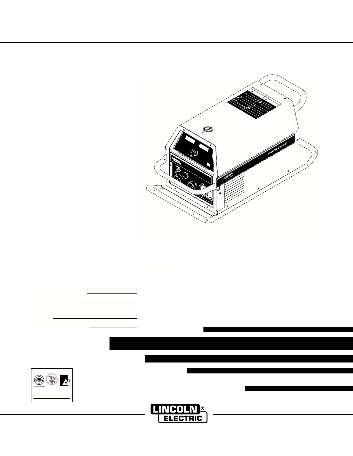
INVERTEC V350-PRO (CE)
Lor
em
ipsu
m do
lor sit amet
consectetuer a
d
ip
i
s
c
in
g
elit,
ed
di
am
n
o
n
u
mm
y ni
bh euismo
d t
incidu
nt ut
lao
reet dol
ore magna
aliquam er
at
Loremi
p
su
m
do
l
or si
t a
m
e
t conse
ctetuer adi
pis
cing
eli
t, ed
d
iam
n
on
umm
y
nibh euismod tinci
dunt
ut
laoreet dolor
e
mag
na aliquam
e
r
at
Lorem i
psum dol
or si
t
amet co
nsectetuer
a
dipisci
ng
elit, ed di
a
m
no
n
u
mm
y
ni
bh eu
ismod tincidunt ut
lao
ree
t dol
ore magna ali
quam er
at
Lorem ips
um do
lor sit amet c
o
nsectetuer
a
d
ipi
s
cing
elit, ed diam no
n
umm
y nibh eui
s
m
od tinc
i
dunt ut
laoreet do
l
o
r
e
m
agna aliquam
e
r
at
Lorem i
p
sum do
lor s
i
t
am
et con
s
ectetuer adi
piscing
elit,
e
d diam
n
o
n
umm
y nibh eui
smod tincidunt ut
laoreet dolore m
a
g
n
a ali
quam er
at
Lorem i
ps
um dolor sit
a
m
e
t c
o
n
s
e
c
tetuer adip
isc
i
ng
e
l
it
,
ed diam non
umm
y nibh e
uis
m
od t
inc
idunt u
t
laoreet
dolore
mag
n
aa
li
quam
er
at
Lorem
ipsu
m dolor
s
it ametconsectetue
r adi
p
isc
ing
el
it, e
ddiamn
on
u
mm
y nibh eui
s
mod tin
c
idunt ut
laoreet d
ol
ore
magnaaliqu
am er
a
t
Lorem ip
sum
dol
orsi
t amet c
onsectetue
r
a
dipis
cing
elit,
eddiamnon
umm
y nibh euis
m
o
d tin
c
idunt
ut
laoreet do
l
ore
m
agna aliquamer
at
L
o
rem ipsum dolor sit a
m
e
t cons
ectetuer
adipiscing
elit,
ed
diamn
on
umm
y nibh euismod ti
ncidunt ut
l
aoreet dol
ore magna a
l
iq
u
am
er
at
Lorem
ipsum dol
or s
it
ametc
onsectetueradipiscing
e
lit,
ed
diam non
u
m
m
y
nib
h euism
o
dtincidun
t ut
laoreet do
l
ore
m
ag
na aliquam
e
r
at
L
orem
ipsum dolorsit amet co
nsectetuer a
d
i
pisci
ng
elit,
e
d
diam non
umm
y nibh euis
m
od tinci
dunt ut
la
oreet
dolore ma
g
na al
iquame
r
at
Loremips
um
d
olor si
t ame
t
consect
e
tuerad
ipisci
n
g
e
lit, ed diamnon
umm
y nibh
euismo
d tincidun
t
ut
l
a
oreet
dolore
magna ali
q
uam er
at
Lorem ip
sum
dolorsit am
e
t consectetuera
dipisc
ing
elit, ed diam non
u
m
m
y nibh eu
ism
od tinc
idunt ut
laore
etd
olore
m
agna aliqua
m er
at
Lorem i
psum dolor sit amet
co
nsectetuer a
dipiscing
elit, ed diam n
o
n
umm
y nibh euismod tincid
u
n
t
u
t
laoreet dolore magna a
l
iq
uam e
r
at
Lorem ipsum dolor s
it a
met consectetuer adipi
s
ci
n
g
elit, ed diam n
on
umm
y nibh euismod tinci
d
un
t
u
t
laoreet dolore magna aliquam er
at
Lorem ipsum dolor sit a
met co
nse
ctetu
er
a
d
i
p
iscing
elit, ed di
am non
umm
y nibh euismod tinci
d
unt
u
t
laoreet dolore magna a
l
iqu
a
m
er
at
Lorem ipsum dolor si
t
ame
t
con
se
c
t
e
t
ue
r
a
dipisc
in
g
elit, ed diam n
on
umm
y nibh e
uismod
tincidunt ut
laoreet dolore magna a
l
i
q
u
a
m er
at
L
orem ipsum dolor sit amet
cons
e
ctetuer
a
dipiscing
elit,
ed dia
mnon
umm
y
n
ibh euis
m
o
d
t
incidunt
ut
l
aoreetdoloremagn
a al
iquam
er
a
t
Lor
em ipsum dolorsit
amet
cons
ectetuer a
dipiscing
elit,
e
d d
iam
non
umm
y nibh eui
sm
od tin
cidun
t
u
t
laoreet dolo
re magn
a
a
l
iqu
am er
at
RETURN TO MAIN MENU
Safety Depends on You
Lincoln arc welding and cutting
equipment is designed and built
with safety in mind. However, your
overall safety can be increased by
proper installation ... and thoughtful operation on your part. DO
NOT INSTALL, OPERATE OR
REPAIR THIS EQUIPMENT
WITHOUT READING THIS
MANUAL AND THE SAFETY
PRECAUTIONS CONTAINED
THROUGHOUT. And, most
importantly, think before you act
and be careful.
™
For use with machines Code; 10670
A
AMPS
V
VOLTS
A
W
ARNING
OUTPUT
INVERTEC V350-PRO
REMOTE
ON
OF
F
WELD TERMINALS
SELECT
POWE
R
LINCOLN
ELECTRIC
elit, ed diam n
laoreet dolore magna aliquam er
Lorem ipsum dolor sit amet consecte
elit, ed diam non
laoreet dolore magna aliquam er
Lorem ipsum dolor sit amet consec
on
umm
umm
y nibh euismod tincidunt ut
IM708
January, 2001
!
WARNING
!
WARNING
L
o
r
e
m
e
l
i
i
t
p
,
s
ed
lao
u
m
d
re
L
i
d
o
a
e
o
r
m
t
e
lor
d
mi
e
no
o
l
s
it
lo
p
n
it
,
r
s
u
ed
ema
lao
a
u
m
m
md
m
d
re
e
L
i
t
y
a
gn
e
o
ol
c
m
n
t
r
o
e
o
ib
a
do
n
m
no
rsit
e
h
s
a
l
lit,
e
o
li
ip
n
eu
q
c
r
u
e
sum
a
te
u
ed
m
la
i
m
s
am
m
tue
o
m
mo
et
d
a
ree
y
e
i
do
gn
ra
a
con
dtin
n
r
m
t
L
a
lo
ib
a
d
d
o
t
n
ip
rsi
he
s
ali
o
r
c
e
o
e
l
is
i
o
mip
n
q
d
c
t
e
uism
ci
rem
u
te
ua
u
a
lit,
m
n
n
m
tue
me
g
t
s
m
ed
e
l
ut
u
a
o
a
t
yn
ra
m
g
d
o
c
r
d
na
r
a
o
t
e
d
i
do
ib
in
t
a
n
e
i
!
pisc
m
h
c
secte
a
td
l
or
i
liq
L
d
e
n
o
o
u
u
o
u
in
s
r
lo
nt
is
e
n
a
it
g
t
r
m
mip
u
u
m
e
elit,e
am
u
e
m
o
t
m
ra
er
dt
m
e
s
ag
a
t
la
y
u
t
d
c
md
o
n
n
L
o
di
r
ibhe
aa
o
n
e
r
a
s
et
e
o
m
e
l
e
mip
l
i
o
q
c
d
u
lit,
n
r
t
u
o
e
ism
o
a
si
l
t
o
s
n
u
m
e
ta
l
r
u
a
umm
e
d
em
o
md
o
ra
e
met
d
di
r
r
e
a
ti
d
a
a
e
t
o
n
y
ip
m
g
td
l
c
co
or
n
n
is
id
n
ib
aa
o
n
c
u
o
s
lo
i
h
sectetu
n
n
itam
Lo
li
re
t
um
e
q
ut
u
u
r
m
is
e
am
m
e
mip
ag
m
e
tco
y n
e
l
o
i
n
t,
r
e
dt
ibh
a a
e
r
s
a
n
a
l
u
d
a
s
in
dd
t
md
ip
oree
e
l
e
i
cidu
q
c
isc
u
ia
t
u
e
is
o
a
mn
tu
i
t
lo
n
m
n
m
d
g
tu
e
r
o
o
ra
e
on
s
dt
lo
t
r
it
a
re
d
u
in
a
t
i
m
p
m
c
m
is
m
id
e
a
c
tco
yn
un
g
i
n
n
g
t
ibh
a
nsecte
u
a
t
liqu
e
ui
s
a
t
m
u
m
e
o
e
ra
dt
r
y nibh euism
a
d
inc
t
i
p
i
i
s
d
cin
u
n
g
t
u
t
tetue
od tincidunt ut
at
r adipisc
tuer adipiscing
ing
at
Lorem ipsum
elit, ed diam non
laoreet
la
L
Lorem ipsum dolor sit amet consectetuer adipiscing
o
e
elit, ed diam non
d
l
i
t
,
dolore magna ali
olor sit amet consectetuer adipiscing
la
e
dd
laoreet dolore magna
oree
umm
t
d
o
l
y nibh eui
umm
quam er
y nibh euism
smod tincidunt ut
aliquam er
at
od tincidunt ut
at
ATTENTION
d
in
i
p
ci
i
s
du
ci
!
n
n
g
tu
t
AVISO DE
PRECAUCION
ng
L
o
r
e
mip
elit,e
s
la
u
d
md
o
dia
r
L
e
o
et
o
r
m
e
lo
d
m
e
n
r
o
l
o
s
it,
l
i
o
p
n
i
ta
r
s
u
e
em
lao
u
mm
d
m
m
d
re
e
a
L
i
d
tcon
y
a
g
e
o
o
m
n
n
t
r
lor
e
i
aa
d
b
m
no
o
e
h
sectetu
s
lo
l
l
it
ip
n
it
e
iq
,
r
u
ui
ema
s
a
u
ed
m
lao
L
u
m
s
am
o
m
m
m
e
r
d
r
e
e
t
y
e
o
i
d
gn
r
e
a
m
c
e
dtin
e
o
n
r
m
a
o
t
a
l
l
a
i
i
o
di
b
i
n
do
t,
p
t
no
r
h
s
al
p
sum
c
e
e
s
l
l
is
ao
e
iqu
id
orem
d d
n
i
ct
t
uism
ci
u
u
a
e
ree
m
am
n
n
ia
do
m
t
u
g
t
m
m
e
e
ut
t
a
o
lo
t
y
ra
e
do
g
d
L
n
rsi
c
r
n
n
a
ore
o
o
ti
dipis
lo
ib
a
t
n
n
n
t
r
h
u
c
s
a
e
a
mip
i
e
m
e
li
d
m
eu
m
q
c
lit,e
c
u
m
te
u
i
e
n
nt
a
is
am
s
t
y
g
tue
g
l
m
u
c
a
d
u
n
na
md
o
o
o
t
ib
dia
n
ra
e
r
dtin
e
he
s
a
r
L
a
e
ecte
o
l
o
d
mn
i
t
td
q
l
r
ipisc
o
u
e
u
c
r
i
mip
o
i
sm
a
d
e
t
o
s
lo
u
m
u
l
n
i
it,
i
t
e
n
r
n
o
umm
e
am
ra
e
s
g
t
d
e
l
r
u
a
ut
m
a
d
t
d
m
o
i
e
t
n
a
ip
d
r
tco
y
ci
e
g
ia
do
i
s
n
e
na
d
mn
ci
ib
td
u
lor
n
a
n
n
he
s
o
g
t
e
l
o
s
iq
l
u
ct
orem
n
i
u
t
t
u
um
e
is
am
a
tue
m
m
L
m
e
ore
o
a
r
e
t
yn
d
gn
r
a
c
at
ti
m
d
o
e
ib
a
n
i
n
li
p
c
ips
he
t
se
aliq
is
,
id
e
cing
c
u
u
u
dd
te
u
nt
m
ore
is
a
rem
t
m
ue
me
u
ia
do
e
t
o
mn
t
r
l
d
or
d
ip
r
a
at
ti
o
d
s
o
s
ncidu
lo
i
u
p
n
it
m
r
is
u
e
am
m
ci
i
d
m
am
m
ng
n
olo
e
ag
t
t
yn
u
c
n
rsi
n
t
o
o
ib
aa
o
n
n
t
he
r
se
u
em
a
liq
m
m
c
ui
m
tetu
u
e
a
sm
am
t
y
g
c
n
na
e
o
o
ibh
ra
e
n
d
r
s
a
a
t
di
e
l
i
t
e
iq
n
c
p
ui
c
t
ua
i
e
i
s
s
d
tu
ci
m
m
u
e
n
nt
o
r
er
g
dt
u
a
a
t
d
i
t
n
ip
c
i
id
s
c
u
in
n
g
t
u
t
Date of Purchase:
Serial Number:
Code Number:
Model:
Where Purchased:
ISO 9001
Designed and Manufactured Under a
Quality Program Certified by
ABS Quality Evaluations, Inc.
to ISO 9001 Requirements.
CERTIFICATE NUMBER: 30273
Cleveland, Ohio 44117-1199 U.S.A. TEL: 216.481.8100 FAX: 216.486.1751 WEB SITE: www.lincolnelectric.com
ANSI RAB
QMS
IEC 974-1
IP21S
OPERATOR’S MANUAL
Copyright © 2001 Lincoln Global Inc.
• World's Leader in Welding and Cutting Products •
• Sales and Service through Subsidiaries and Distributors Worldwide •
Page 2
i
SAFETY
i
WARNING
CALIFORNIA PROPOSITION 65 WARNINGS
Diesel engine exhaust and some of its constituents
are known to the State of California to cause cancer, birth defects, and other reproductive harm.
The Above For Diesel Engines
ARC WELDING CAN BE HAZARDOUS. PROTECT YOURSELF AND OTHERS FROM POSSIBLE SERIOUS INJURY OR DEATH.
KEEP CHILDREN AWAY. PACEMAKER WEARERS SHOULD CONSULT WITH THEIR DOCTOR BEFORE OPERATING.
Read and understand the following safety highlights. For additional safety information, it is strongly recommended that you
purchase a copy of “Safety in Welding & Cutting - ANSI Standard Z49.1” from the American Welding Society, P.O. Box
351040, Miami, Florida 33135 or CSA Standard W117.2-1974. A Free copy of “Arc Welding Safety” booklet E205 is available
from the Lincoln Electric Company, 22801 St. Clair Avenue, Cleveland, Ohio 44117-1199.
BE SURE THAT ALL INSTALLATION, OPERATION, MAINTENANCE AND REPAIR PROCEDURES ARE
PERFORMED ONLY BY QUALIFIED INDIVIDUALS.
The engine exhaust from this product contains
chemicals known to the State of California to cause
cancer, birth defects, or other reproductive harm.
The Above For Gasoline Engines
FOR ENGINE
powered equipment.
1.a. Turn the engine off before troubleshooting and maintenance
work unless the maintenance work requires it to be running.
____________________________________________________
1.b.Operate engines in open, well-ventilated
areas or vent the engine exhaust fumes
outdoors.
____________________________________________________
1.c. Do not add the fuel near an open flame
welding arc or when the engine is running.
Stop the engine and allow it to cool before
refueling to prevent spilled fuel from vaporizing on contact with hot engine parts and
igniting. Do not spill fuel when filling tank. If
fuel is spilled, wipe it up and do not start
engine until fumes have been eliminated.
____________________________________________________
1.d. Keep all equipment safety guards, covers and devices in
position and in good repair.Keep hands, hair, clothing and
tools away from V-belts, gears, fans and all other moving
parts when starting, operating or repairing equipment.
____________________________________________________
1.e. In some cases it may be necessary to remove safety
guards to perform required maintenance. Remove
guards only when necessary and replace them when the
maintenance requiring their removal is complete.
Always use the greatest care when working near moving
parts.
___________________________________________________
1.f. Do not put your hands near the engine fan.
Do not attempt to override the governor or
idler by pushing on the throttle control rods
while the engine is running.
1.h. To avoid scalding, do not remove the
radiator pressure cap when the engine is
hot.
ELECTRIC AND
MAGNETIC FIELDS
may be dangerous
2.a. Electric current flowing through any conductor causes
localized Electric and Magnetic Fields (EMF). Welding
current creates EMF fields around welding cables and
welding machines
2.b. EMF fields may interfere with some pacemakers, and
welders having a pacemaker should consult their physician
before welding.
2.c. Exposure to EMF fields in welding may have other health
effects which are now not known.
2.d. All welders should use the following procedures in order to
minimize exposure to EMF fields from the welding circuit:
2.d.1.
Route the electrode and work cables together - Secure
them with tape when possible.
2.d.2. Never coil the electrode lead around your body.
2.d.3. Do not place your body between the electrode and
work cables. If the electrode cable is on your right
side, the work cable should also be on your right side.
___________________________________________________
1.g. To prevent accidentally starting gasoline engines while
turning the engine or welding generator during maintenance
work, disconnect the spark plug wires, distributor cap or
magneto wire as appropriate.
2.d.4. Connect the work cable to the workpiece as close as
possible to the area being welded.
2.d.5. Do not work next to welding power source.
Mar ‘95
Page 3
ii
SAFETY
ii
ELECTRIC SHOCK can
kill.
3.a. The electrode and work (or ground) circuits
are electrically “hot” when the welder is on.
Do not touch these “hot” parts with your bare
skin or wet clothing. Wear dry, hole-free
gloves to insulate hands.
3.b. Insulate yourself from work and ground using dry insulation.
Make certain the insulation is large enough to cover your full
area of physical contact with work and ground.
In addition to the normal safety precautions, if welding
must be performed under electrically hazardous
conditions (in damp locations or while wearing wet
clothing; on metal structures such as floors, gratings or
scaffolds; when in cramped positions such as sitting,
kneeling or lying, if there is a high risk of unavoidable or
accidental contact with the workpiece or ground) use
the following equipment:
• Semiautomatic DC Constant Voltage (Wire) Welder.
• DC Manual (Stick) Welder.
• AC Welder with Reduced Voltage Control.
3.c. In semiautomatic or automatic wire welding, the electrode,
electrode reel, welding head, nozzle or semiautomatic
welding gun are also electrically “hot”.
3.d. Always be sure the work cable makes a good electrical
connection with the metal being welded. The connection
should be as close as possible to the area being welded.
3.e. Ground the work or metal to be welded to a good electrical
(earth) ground.
ARC RAYS can burn.
4.a. Use a shield with the proper filter and cover
plates to protect your eyes from sparks and
the rays of the arc when welding or observing
open arc welding. Headshield and filter lens
should conform to ANSI Z87. I standards.
4.b. Use suitable clothing made from durable flame-resistant
material to protect your skin and that of your helpers from
the arc rays.
4.c. Protect other nearby personnel with suitable, non-flammable
screening and/or warn them not to watch the arc nor expose
themselves to the arc rays or to hot spatter or metal.
FUMES AND GASES
can be dangerous.
5.a.Welding may produce fumes and gases
hazardous to health. Avoid breathing these
fumes and gases.When welding, keep
your head out of the fume. Use enough
ventilation and/or exhaust at the arc to keep
fumes and gases away from the breathing zone. When
welding with electrodes which require special
ventilation such as stainless or hard facing (see
instructions on container or MSDS) or on lead or
cadmium plated steel and other metals or coatings
which produce highly toxic fumes, keep exposure as
low as possible and below Threshold Limit Values (TLV)
using local exhaust or mechanical ventilation. In
confined spaces or in some circumstances, outdoors, a
respirator may be required. Additional precautions are
also required when welding on galvanized steel.
3.f.
Maintain the electrode holder, work clamp, welding cable and
welding machine in good, safe operating condition. Replace
damaged insulation.
3.g. Never dip the electrode in water for cooling.
3.h. Never simultaneously touch electrically “hot” parts of
electrode holders connected to two welders because voltage
between the two can be the total of the open circuit voltage
of both welders.
3.i. When working above floor level, use a safety belt to protect
yourself from a fall should you get a shock.
3.j. Also see Items 6.c. and 8.
5.b.
Do not weld in locations near chlorinated hydrocarbon
coming from degreasing, cleaning or spraying operations.
The heat and rays of the arc can react with solvent vapors
form phosgene, a highly toxic gas, and other irritating products.
5.c. Shielding gases used for arc welding can displace air and
cause injury or death. Always use enough ventilation,
especially in confined areas, to insure breathing air is safe.
5.d. Read and understand the manufacturer’s instructions for this
equipment and the consumables to be used, including the
material safety data sheet (MSDS) and follow your
employer’s safety practices. MSDS forms are available from
your welding distributor or from the manufacturer.
5.e. Also see item 1.b.
vapors
Mar ‘95
to
Page 4

iii
SAFETY
iii
WELDING SPARKS can
cause fire or explosion.
6.a.
Remove fire hazards from the welding area.
If this is not possible, cover them to prevent
the welding sparks from starting a fire.
materials from welding can easily go through small cracks
and openings to adjacent areas. Avoid welding near
hydraulic lines. Have a fire extinguisher readily available.
6.b. Where compressed gases are to be used at the job site,
special precautions should be used to prevent hazardous
situations. Refer to “Safety in Welding and Cutting” (ANSI
Standard Z49.1) and the operating information for the
equipment being used.
6.c. When not welding, make certain no part of the electrode
circuit is touching the work or ground. Accidental contact
can cause overheating and create a fire hazard.
6.d. Do not heat, cut or weld tanks, drums or containers until the
proper steps have been taken to insure that such procedures
will not cause flammable or toxic vapors from substances
inside. They can cause an explosion even
been “cleaned”. For information, purchase “Recommended
Safe Practices for the
Containers and Piping That Have Held Hazardous
Substances”, AWS F4.1 from the American Welding Society
(see address above).
6.e. Vent hollow castings or containers before heating, cutting or
welding. They may explode.
Sparks and spatter are thrown from the welding arc. Wear oil
6.f.
free protective garments such as leather gloves, heavy shirt,
cuffless trousers, high shoes and a cap over your hair. Wear
ear plugs when welding out of position or in confined places.
Always wear safety glasses with side shields when in a
welding area.
6.g. Connect the work cable to the work as close to the welding
area as practical. Work cables connected to the building
framework or other locations away from the welding area
increase the possibility of the welding current passing
through lifting chains, crane cables or other alternate circuits. This can create fire hazards or overheat lifting chains
or cables until they fail.
6.h. Also see item 1.c.
Remember that welding sparks and hot
though
they have
Preparation
for Welding and Cutting of
CYLINDER may explode
if damaged.
7.a. Use only compressed gas cylinders
containing the correct shielding gas for the
process used and properly operating
regulators designed for the gas and
pressure used. All hoses, fittings, etc. should be suitable for
the application and maintained in good condition.
7.b. Always keep cylinders in an upright position securely
chained to an undercarriage or fixed support.
7.c. Cylinders should be located:
• Away from areas where they may be struck or subjected to
physical damage.
• A safe distance from arc welding or cutting operations and
any other source of heat, sparks, or flame.
7.d. Never allow the electrode, electrode holder or any other
electrically “hot” parts to touch a cylinder.
7.e. Keep your head and face away from the cylinder valve outlet
when opening the cylinder valve.
7.f. Valve protection caps should always be in place and hand
tight except when the cylinder is in use or connected for
use.
7.g. Read and follow the instructions on compressed gas
cylinders, associated equipment, and CGA publication P-l,
“Precautions for Safe Handling of Compressed Gases in
Cylinders,” available from the Compressed Gas Association
1235 Jefferson Davis Highway, Arlington, VA 22202.
FOR ELECTRICALLY
powered equipment.
8.a. Turn off input power using the disconnect
switch at the fuse box before working on
the equipment.
8.b. Install equipment in accordance with the U.S. National
Electrical Code, all local codes and the manufacturer’s
recommendations.
8.c. Ground the equipment in accordance with the U.S. National
Electrical Code and the manufacturer’s recommendations.
Mar ‘95
Page 5

iv
SAFETY
iv
PRÉCAUTIONS DE SÛRETÉ
Pour votre propre protection lire et observer toutes les instructions
et les précautions de sûreté specifiques qui parraissent dans ce
manuel aussi bien que les précautions de sûreté générales suiv-
antes:
Sûreté Pour Soudage A L’Arc
1. Protegez-vous contre la secousse électrique:
a. Les circuits à l’électrode et à la piéce sont sous tension
quand la machine à souder est en marche. Eviter toujours
tout contact entre les parties sous tension et la peau nue
ou les vétements mouillés. Porter des gants secs et sans
trous pour isoler les mains.
b. Faire trés attention de bien s’isoler de la masse quand on
soude dans des endroits humides, ou sur un plancher
metallique ou des grilles metalliques, principalement dans
les positions assis ou couché pour lesquelles une grande
partie du corps peut être en contact avec la masse.
c. Maintenir le porte-électrode, la pince de masse, le câble
de soudage et la machine à souder en bon et sûr état
defonctionnement.
d.Ne jamais plonger le porte-électrode dans l’eau pour le
refroidir.
e. Ne jamais toucher simultanément les parties sous tension
des porte-électrodes connectés à deux machines à souder
parce que la tension entre les deux pinces peut être le
total de la tension à vide des deux machines.
f. Si on utilise la machine à souder comme une source de
courant pour soudage semi-automatique, ces precautions
pour le porte-électrode s’applicuent aussi au pistolet de
soudage.
zones où l’on pique le laitier.
6. Eloigner les matériaux inflammables ou les recouvrir afin de
prévenir tout risque d’incendie dû aux étincelles.
7. Quand on ne soude pas, poser la pince à une endroit isolé de
la masse. Un court-circuit accidental peut provoquer un
échauffement et un risque d’incendie.
8. S’assurer que la masse est connectée le plus prés possible
de la zone de travail qu’il est pratique de le faire. Si on place
la masse sur la charpente de la construction ou d’autres
endroits éloignés de la zone de travail, on augmente le risque
de voir passer le courant de soudage par les chaines de levage, câbles de grue, ou autres circuits. Cela peut provoquer
des risques d’incendie ou d’echauffement des chaines et des
câbles jusqu’à ce qu’ils se rompent.
9. Assurer une ventilation suffisante dans la zone de soudage.
Ceci est particuliérement important pour le soudage de tôles
galvanisées plombées, ou cadmiées ou tout autre métal qui
produit des fumeés toxiques.
10. Ne pas souder en présence de vapeurs de chlore provenant
d’opé rations de dégraissage, nettoyage ou pistolage. La
chaleur ou les rayons de l’arc peuvent réagir avec les vapeurs
du solvant pour produire du phosgéne (gas fortement toxique)
ou autres produits irritants.
11. Pour obtenir de plus amples renseignements sur la sûreté,
voir le code “Code for safety in welding and cutting” CSA
Standard W 117.2-1974.
2. Dans le cas de travail au dessus du niveau du sol, se prot
contre les chutes dans le cas ou on recoit un choc. Ne jamais
enrouler le câble-électrode autour de n’importe quelle partie
du corps.
3. Un coup d’arc peut être plus sévère qu’ un coup de soliel,
donc:
a. Utiliser un bon masque avec un verre filtrant approprié
ainsi qu’un verre blanc afin de se protéger les yeux du rayonnement de l’arc et des projections quand on soude ou
quand on regarde l’arc.
b. Porter des vêtements convenables afin de protéger la
peau de soudeur et des aides contre le rayonnement de
l‘arc.
c. Protéger l’ autre personnel travaillant à proximité au
soudage à l’aide d’écrans appropriés et non-inflammables.
4. Des gouttes de laitier en fusion sont émises de l’ arc de
soudage. Se protéger avec des vêtements de protection libres
de l’huile, tels que les gants en cuir, chemise épaisse, pantalons sans revers, et chaussures montantes.
5. Toujours porter des lunettes de sécurité dans la zone de
soudage. Utiliser des lunettes avec écrans lateraux dans les
éger
PRÉCAUTIONS DE SÛRETÉ POUR
LES MACHINES À SOUDER À
TRANSFORMATEUR ET À
REDRESSEUR
1. Relier à la terre le chassis du poste conformement au code de
l’électricité et aux recommendations du fabricant. Le dispositif
de montage ou la piece à souder doit être branchéà une
bonne mise à la terre.
2. Autant que possible, I’installation et l’entretien du poste seront
effectués par un électricien qualifié.
3. Avant de faires des travaux à l’interieur de poste, la debrancher à l’interrupteur à la boite de fusibles.
4. Garder tous les couvercles et dispositifs de sûretéà leur
place.
Mar. ‘93
Page 6

v
ELECTROMAGNETIC COMPATIBILITY (EMC)
Conformance
Products displaying the CE mark are in conformity with European Community Council Directive of 3 May
1989 on the approximation of the laws of the Member States relating to electromagnetic compatibility
(89/336/EEC). It was manufactured in conformity with a national standard that implements a harmonized
standard: EN 50 199 Electromagnetic Compatibility (EMC) Product Standard for Arc Welding Equipment. It
is for use with other Lincoln Electric equipment. It is designed for industrial and professional use.
Introduction
All electrical equipment generates small amounts of electromagnetic emission. Electrical emission may be
transmitted through power lines or radiated through space, similar to a radio transmitter. When emissions are
received by other equipment, electrical interference may result. Electrical emissions may affect many kinds of
electrical equipment; other nearby welding equipment, radio and TV reception, numerical controlled machines,
telephone systems, computers, etc. Be aware that interference may result and extra precautions may be required
when a welding power source is used in a domestic establishment.
SAFETY
v
Installation and Use
The user is responsible for installing and using the welding equipment according to the manufacturer s instructions.
If electromagnetic disturbances are detected then it shall be the responsibility of the user of the welding equipment
to resolve the situation with the technical assistance of the manufacturer. In some cases this remedial action may
be as simple as earthing (grounding) the welding circuit, see Note. In other cases it could involve constructing an
electromagnetic screen enclosing the power source and the work complete with associated input filters. In all cases
electromagnetic disturbances must be reduced to the point where they are no longer troublesome.
Note: The welding circuit may or may not be earthed for safety reasons according to national codes.
Changing the earthing arrangements should only be authorized by a person who is competent to
assess whether the changes will increase the risk of injury, e.g., by allowing parallel welding
current return paths which may damage the earth circuits of other equipment.
Assessment of Area
Before installing welding equipment the user shall make an assessment of potential electromagnetic problems in the
surrounding area. The following shall be taken into account:
a) other supply cables, control cables, signaling and telephone cables; above, below and adjacent to the
welding equipment;
b) radio and television transmitters and receivers;
c) computer and other control equipment;
d) safety critical equipment, e.g., guarding of industrial equipment;
e) the health of the people around, e.g., the use of pacemakers and hearing aids;
f) equipment used for calibration or measurement;
g) the immunity of other equipment in the environment. The user shall ensure that other equipment being
used in the environment is compatible. This may require additional protection measures;
h) the time of day that welding or other activities are to be carried out.
V350-PRO (CE)
3-1-96H
L10093
Page 7

vi
r
t
s
u
m
n
r
p
o
e
s
o
e
H
h
s
g
SAFETY
ELECTROMAGNETIC COMPATIBILITY (EMC)
The size of the surrounding area to be considered will depend on the structure of the building and othe
that are taking place. The surrounding area may extend beyond the boundaries of the premises.
Methods of Reducing Emissions
Mains Supply
Welding equipment should be connected to the mains supply according to the manufacturer s recomm
If interference occurs, it may be necessary to take additional precautions such as filtering of the mains
Consideration should be given to shielding the supply cable of permanently installed welding equipmen
conduit or equivalent. Shielding should be electrically continuous throughout its length. The shielding
connected to the welding power source so that good electrical contact is maintained between the cond
welding power source enclosure.
Maintenance of the Welding Equipment
The welding equipment should be routinely maintained according to the manufacturer s recommendati
access and service doors and covers should be closed and properly fastened when the welding equip
operation. The welding equipment should not be modified in any way except for those changes and adj
covered in the manufacturers instructions. In particular, the spark gaps of arc striking and stabilizing d
be adjusted and maintained according to the manufacturer s recommendations.
Welding Cables
The welding cables should be kept as short as possible and should be positioned close together, runni
to the floor level.
vi
Equipotential Bonding
Bonding of all metallic components in the welding installation and adjacent to it should be considered.
metallic components bonded to the work piece will increase the risk that the operator could receive a s
touching these metallic components and the electrode at the same time. The operator should be insula
such bonded metallic components.
Earthing of the Workpiece
Where the workpiece is not bonded to earth for electrical safety, not connected to earth because of its
position, e.g., ships hull or building steelwork, a connection bonding the workpiece to earth may reduce
in some, but not all instances. Care should be taken to prevent the earthing of the workpiece increasin
of injury to users, or damage to other electrical equipment. Where necessary, the connection of the wo
earth should be made by a direct connection to the workpiece, but in some countries where direct conn
permitted, the bonding should be achieved by suitable capacitance, selected according to national regu
Screening and Shielding
Selective screening and shielding of other cables and equipment in the surrounding area may alleviate
interference. Screening of the entire welding installation may be considered for special applications.
1
Portions of the preceding text are contained in EN50199: "Electromagnetic Compatibility (EMC) pr
arc welding equipment."
1
V350-PRO (CE)
Page 8

for selecting a QUALITY product by Lincoln Electric. We want you
Thank You
to take pride in operating this Lincoln Electric Company product
••• as much pride as we have in bringing this product to you!
Please Examine Carton and Equipment For Damage Immediately
When this equipment is shipped, title passes to the purchaser upon receipt by the carrier. Consequently, Claims
for material damaged in shipment must be made by the purchaser against the transportation company at the
time the shipment is received.
Please record your equipment identification information below for future reference. This information can be
found on your machine nameplate.
Model Name & Number _____________________________________
Code & Serial Number _____________________________________
Date of Purchase _____________________________________
Whenever you request replacement parts for or information on this equipment always supply the information
you have recorded above.
viivii
Read this Operators Manual completely before attempting to use this equipment. Save this manual and keep it
handy for quick reference. Pay particular attention to the safety instructions we have provided for your protection.
The level of seriousness to be applied to each is explained below:
WARNING
This statement appears where the information must be followed exactly to avoid serious personal injury or
loss of life.
CAUTION
This statement appears where the information must be followed to avoid minor personal injury or damage to
this equipment.
Page 9

viii
TABLE OF CONTENTS
Page
Installation.......................................................................................................Section A
Technical Specifications........................................................................................A-1
Safety Precautions..........................................................................................A-2
Select Suitable Location..................................................................................A-2
Stacking ..........................................................................................................A-2
Tilting...............................................................................................................A-2
Input and Grounding Connections ..................................................................A-2
Power Cord Connection..................................................................................A-2
Connection of Wire Feeders to V350-PRO (CE).............................................A-2
Remote Control of Invertec.............................................................................A-3
Undercarriage Mountings................................................................................A-3
Parallel Operations..........................................................................................A-4
Ouick Disconnect Plugs..................................................................................A-4
Operation.........................................................................................................Section B
Additional Safety Precautions ...............................................................................B-1
General Description and Duty Cycle......................................................................B-1
Operational Features and Controls.........................................................B-1 Thru B-3
Remote Control of the Output Control and Weld Terminals..................................B-3
Design Features and Advantages .........................................................................B-4
Auxiliary Power......................................................................................................B-5
Limitations..............................................................................................................B-5
Recommended Processes ....................................................................................B-5
viii
Accessories.....................................................................................................Section C
General Options / Accessories..............................................................................C-1
“CE” Version........................................................................................................................
Field Installed Options/Accessories.......................................................................C-1
Maintenance ....................................................................................................Section D
Safety Precautions ................................................................................................D-1
C
APACITOR DISCHARGE PROCEDURE..........................................................................D-1
VISUAL INSPECTION...................................................................................................D-1
R
OUTINE MAINTENANCE ............................................................................................D-1
PERIODIC MAINTENANCE ...........................................................................................D-1
Section E ..............................................................................................Troubleshooting
Safety Precautions.................................................................................................E-1
How to Use Troubleshooting Guide.......................................................................E-1
Troubleshooting Guide ...........................................................................E-2 Thru E-3
Fault Codes ...........................................................................................................E-4
Displays.................................................................................................................E-5
Connection , Wiring Diagrams and Dimension Prints .................................Section F
Parts List ......................................................................................................P389 Series
C-1
Page 10
A-1
INSTALLATION
A-1
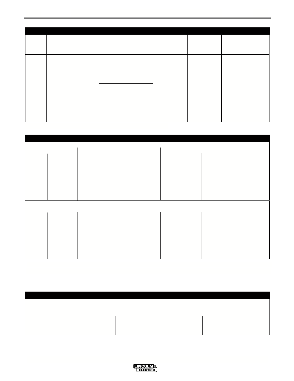
TECHNICAL SPECIFICATIONS -
INVERTEC V350-PRO (CE)
INPUT AC VOLTAGE & DC OUTPUT
Product Ordering Input AC Rated DC Output Output Weight Dimensions
Name Information Voltage Amps/Volts/Duty Cycle Range with Cord HxWxD
50/60 Hz (continuous)
350A / 34V / 60% 14.7”x12.5”x
Invertec 200-220/ 3 Phase 27.8”*
V350- K1728-3 380-400/ 320A / 33V / 60% AMPS 82.5lbs (373x318x
PRO “CE” 415-440/ 1 Phase 5-425 (37.4 kg) 706*)mm
60/50 Hz
275A / 31V /100%
1 & 3 Phase * Includes
handles
* Overall Length Including Handle, 27.8” (706mm) without handle.
V350-PRO (CE) INPUT CURRENT (CE)
Recommended Fuse Sizes Based On The U.S. National Electrical Code And Maximum Machine Outputs
Input 50/60 Hz Output Recommended
Voltage Phases 275Amps@ 350Amps@ Line Cord Size Fuse Size Notes
31Volts(100%) 34Volts(60%) AWG[IEC] SIZES
200 3 35 48 6 80A Note 2
220 3 35 48 6 80A Note 2
380 3 21 28 8 50A
400 3 20 27 8 50A
415 3 19 26 8 50A
440 3 18 24 8 50A
Voltage Phases 275Amps@ 320Amps@ Line Cord Size Fuse Size Notes
31Volts(100%) 33Volts(60%)
200 1 ---- ---- --- ----- Note 1
220 1 64 82 4 125A Note 2
380 1 44 55 6 80A Note 2
400 1 40 50 8 80A
415 1 38 48 8 80A
440 1 35 45 8 80A
1. Not rated is indicated by 4-x's in the box on the rating plate
2. When operating on these inputs, the line cord should be changed to an input conductor of 6 AWG or larger.
OUTPUT CABLES, CONNECTIONS AND LIMITATIONS
Select the output cable size based upon the following chart.
Cable sizes for Combined Length of Electrode and Work Cable (Copper) 75C rated:
DUTY CYCLE CURRENT LENGTH UP 61m (200 FT) 61-76m (200-250 FT)
100% 275 1/0 1/0
60% 350 1/0 2/0
V350-PRO (CE)
Page 11

A-2
W
A
R
N
I
N
G
R
E
M
O
T
E
P
O
W
E
R
O
F
F
O
N
A
AM
P
S
A
V
V
O
L
T
S
W
EL
D
T
E
R
MIN
A
L
S
SE
LE
C
T
O
UT
P
U
T
L
I
N
C
OLN
E
L
E
CT
R
I
C
INV
ERTEC V350-PRO
W
A
R
N
I
N
G
W
AR
N
I
N
G
AV
I
S
O
D
E
P
R
EC
A
U
C
I
O
N
A
T
T
E
N
T
IO
N
!
!
!
!
L
o
re
m
ip
s
u
m
d
o
l
o
r
s
i
t
a
m
e
t
c
o
n
s
e
c
te
tu
e
r
a
d
i
p
i
sc
i
n
g
Lo
r
em
ip
sum
d
ol
or
s
i
t
a
me
t
co
ns
e
c
t
e
t
u
e
r
a
d
i
pi
sc
ing
e
l
i
t
,
e
d
d
i
a
m
n
o
n
e
l
it
,
ed
d
i
a
m
n
o
n
u
m
m
u
mm
y
n
i
b
h
e
u
i
s
m
o
d
t
i
n
c
i
d
u
n
t
u
t
y
n
i
bh
e
u
i
sm
o
d
ti
n
ci
d
unt
u
t
l
a
o
r
e
e
t
d
o
l
o
r
e
m
a
g
n
a
a
l
i
q
u
a
m
e
r
lao
r
e
e
t
d
o
lore m
a
gna a
l
iqu
am
e
r
a
tat
L
o
r
e
m
i
p
s
u
m
d
o
l
o
r
s
i
t
a
m
e
t
c
o
n
s
e
ct
e
t
u
e
r
a
d
i
p
i
s
c
i
n
g
L
o
re
m
i
p
s
u
m
d
ol
o
r
s
i
t
a
m
e
t
co
ns
ec
te
t
u
er
a
d
ip
i
s
c
i
n
g
e
li
t
,
e
d
d
ia
m
n
o
n
el
it
,
e
d
d
i
am no
n
u
m
m
u
m
m
y
n
i
b
h
e
u
i
s
m
o
d
t
i
n
c
i
d
u
n
t
u
t
y
n
i
b
h
e
u
i
s
m
o
d
ti
n
cid
unt ut
la
o
r
e
e
t
d
o
l
o
r
e
m
a
g
n
a
a
l
iq
u
a
m
e
r
l
a
ore
e
t d
o
l
or
e
m
ag
na
a
l
iq
u
a
m
er
a
t
at
L
o
r
e
m
i
p
su
m
d
o
l
o
r
s
i
t
a
m
e
t
c
o
n
s
e
c
t
e
t
u
e
r
a
d
i
p
i
s
ci
n
g
L
o
rem
i
psum d
o
l
o
r
si
t
ame
t
c
o
n
sect
etuer ad
i
piscing
e
l
i
t
,
e
d
d
i
a
m
n
o
n
el
it
,
e
d
d
i
a
m
n
o
n
u
mm
umm
y
n
i
b
h
e
u
i
s
m
o
d
ti
n
c
i
d
u
n
t
u
t
y
n
ibh e
u
i
smo
d
tin
c
i
dunt
ut
l
a
o
r
e
e
t
d
o
l
o
re
ma
g
n
a
a
l
i
q
u
a
m
e
r
la
or
eet
d
ol
ore
m
a
gn
a
al
iq
u
a
m
er
a
t
at
L
o
r
e
m
i
p
s
u
m
d
o
l
o
r
s
i
t
a
m
e
t
c
o
n
se
c
t
e
t
u
e
r
a
d
ip
i
s
c
i
n
g
Lo
rem
i
psu
m
d
ol
or
sit
a
m
e
t
c
o
n
s
ect
e
tu
e
r
ad
ip
isc
ing
e
l
i
t
,
e
d
d
ia
m
n
o
n
el
i
t
,
ed
di
a
m
no
n
u
m
m
u
mm
y
n
ib
h
e
u
i
s
m
o
d
t
i
n
c
id
u
n
t
u
t
y
ni
b
h eui
s
mo
d
t
in
c
id
u
n
t u
t
l
a
o
r
e
e
t
d
o
l
o
r
e
ma
g
n
a
a
l
i
q
u
a
m
e
r
l
ao
r
e
et
do
l
o
r
e ma
g
n
a
ali
q
uam
e
r
a
t
a
t
L
o
r
e
m
i
p
s
u
m
d
o
l
o
r
s
i
t
a
me
t
c
o
n
se
c
te
t
u
e
r
a
d
i
p
i
s
c
i
n
g
L
or
e
m
i
p
sum d
o
lor sit
am
e
t
cons
e
ct
e
t
u
e
r
a
dip
i
s
c
i
n
g
e
l
i
t
,
e
d
d
i
a
m
n
o
n
e
l
i
t,
e
d
d
i
a
m
n
o
n
u
m
m
umm
y
n
i
b
h
e
u
i
s
m
o
d
t
in
c
i
d
u
n
t
u
t
y n
i
b
h
euis
mo
d
tinc
i
d
u
nt ut
l
a
o
r
e
e
t
d
o
l
o
r
e
m
a
g
n
a
a
l
i
q
u
a
m
e
r
la
or
e
e
t
d
o
lo
r
e
m
a
g
n
a a
li
qu
a
m
er
at
at
L
o
r
e
m
i
p
su
m
d
o
l
o
r
s
i
t
a
m
e
t
c
o
n
s
e
c
t
e
t
u
e
r
a
d
i
p
i
s
c
i
n
g
L
o
rem
ip
su
m
do
lo
r
sit
amet
con
s
ectetuer
ad
ip
i
s
ci
n
g
e
l
i
t
,
e
d
d
i
a
m
n
o
n
eli
t
, e
d
d
iam
n
o
n
u
m
m
u
m
m
y
n
i
b
h
e
u
i
s
m
o
d
t
i
n
c
i
d
u
n
t
u
t
y
n
i
b
h
e
uism
od
tincid
u
n
t u
t
l
a
o
r
e
e
t
d
o
l
o
r
e
ma
g
n
a
a
l
iq
u
a
m
e
r
l
a
o
r
ee
t
do
l
o
re
m
ag
na
a
liq
u
am
er
a
t
at
L
o
r
e
m
i
p
s
u
m
d
o
l
o
rs
i
t
a
m
e
t
co
n
s
e
c
te
t
u
e
r
a
d
i
p
i
s
c
in
g
Lo
r
e
m i
p
s
u
m
d
o
lor sit
ame
t
con
se
ct
e
t
u
er
adi
p
i
s
ci
n
g
e
l
i
t
,
e
d
d
i
a
m
n
o
n
elit
,
e
d
d
iam
n
o
n
u
m
m
u
m
m
y
n
i
b
h
e
u
i
s
m
o
d
t
in
c
id
u
n
t
u
t
y
ni
bh
e
u
is
mo
d
t
in
c
id
u
nt
ut
la
o
r
e
e
t
d
o
l
o
r
e
m
a
g
n
a
a
l
i
q
u
a
m
e
r
la
oree
t
d
o
l
o
r
e
m
agna aliquam
e
r
a
t
a
t
L
o
r
e
m
i
p
s
u
m
d
o
l
o
r
s
i
t
a
m
e
t
c
o
n
s
e
c
t
e
t
u
e
r
a
d
i
p
i
s
c
i
n
g
L
ore
m
ip
su
m d
o
lor sit
amet
c
o
n
sectetue
r
a
d
ipiscin
g
e
li
t
,
e
d
d
i
a
m
n
o
n
e
l
i
t
,
ed
d
ia
m
n
on
u
m
m
u
m
m
y
n
i
b
h
e
u
i
s
m
o
d
t
i
n
c
i
d
u
n
t
u
t
y
n
i
bh
e
u
i
s
mod
t
i
ncid
u
nt
u
t
l
a
o
r
e
e
t
d
o
l
o
r
e
m
a
g
n
a
a
l
i
q
u
a
m
e
r
l
a
or
e
et
d
ol
o
re
m
agn
a
a
liqua
m
e
r
a
t
a
t
L
o
r
e
m
i
p
s
u
m
d
o
l
o
r
s
it
a
m
e
t
co
n
s
e
c
t
e
t
u
e
r
a
d
i
p
i
sc
i
n
g
L
o
r
em
i
ps
u
m
dol
o
r
s
i
t
a
m
e
t
c
o
nse
c
t
e
t
u
er
ad
ip
i
s
c
i
ng
e
l
i
t
,
e
d
d
i
a
m
n
o
n
e
l
i
t
,
e
d diam no
n
u
m
m
u
m
m
y
n
i
b
h
e
u
i
s
mo
d
ti
n
c
i
d
u
n
t
u
t
yn
i
b
h
e
uis
mo
d
t
i
n
c
i
du
n
t
ut
l
a
o
r
e
e
t
d
o
l
o
r
e
m
a
g
n
a
a
l
i
q
u
a
m
e
r
l
a
oreet
d
o
l
o
r
e ma
g
na
a
l
i
q
uam
e
r
a
t
at
L
o
r
e
m
i
p
su
m
d
o
l
o
rs
i
t
a
m
e
t
c
o
n
s
e
ct
e
tu
e
r
a
d
ip
i
sc
in
g
L
o
rem
i
p
sum
d
o
l
or
si
t a
m
e
t
con
s
e
c
te
t
ue
r
ad
i
p
isc
i
ng
e
li
t,
e
d
d
ia
m
n
o
n
e
li
t
,
e
d d
i
a
m
n
on
u
m
m
u
m
m
y
n
i
b
h
e
u
i
s
m
o
d
ti
n
c
i
d
u
nt
u
t
y
n
ib
h
e
uis
m
od
t
i
n
c
i
d
un
t
u
t
l
a
o
r
e
e
t
d
o
l
o
re
m
a
g
n
a
a
l
i
q
u
a
m
e
r
la
o
ree
t
do
l
o
re m
ag
na
ali
q
uam er
a
t
at
L
o
r
e
m
i
p
s
u
m
d
o
l
o
r
s
i
t
a
m
e
t
c
o
n
s
e
c
t
e
t
u
e
r
a
d
i
p
i
sc
i
n
g
L
o
r
em ips
u
md
olor
si
t
a
m
et con
se
ct
e
t
u
er ad
i
p
i
s
c
i
n
g
e
li
t
,
e
d
d
i
a
m
n
o
n
eli
t
,
e
d
d
i
am
n
o
n
u
m
m
um
m
y
n
ib
he
u
i
s
m
o
d
t
in
cid
u
n
t
u
t
y
n
i
bh eu
i
s
mod
t
in
c
i
d
u
n
t
u
t
la
o
r
e
e
t
d
o
l
o
re
ma
g
n
a
a
l
i
q
u
a
m
e
r
l
ao
r
ee
t
do
lo
r
e
m
ag
n
a
a
l
iq
ua
m
er
a
t
a
t
L
o
r
e
m
i
p
s
u
m
d
o
l
o
r
s
i
t
a
me
t
c
o
n
s
e
ct
e
t
u
e
r
a
d
i
p
i
sc
i
n
g
Lo
r
e
m
ipsum
d
o
lo
r
s
it
am
et
co
n
s
e
ct
e
t
uer
a
dip
i
sc
i
ng
e
l
i
t
,
e
d
d
i
a
m
n
o
n
e
li
t
,
e
d
d
i
a
m
non
u
m
m
u
m
m
y
n
i
b
h
e
u
i
s
mo
d
t
i
n
c
i
d
u
n
t
u
t
y
n
i
b
h
eui
sm
o
d
t
i
nc
id
u
nt
u
t
l
a
o
r
e
e
t
d
o
l
o
r
e
m
a
g
n
a
a
l
iq
u
a
m
e
r
la
or
e
et
d
o
lore
m
agn
a
a
liq
ua
m
er
a
t
at
L
o
r
e
m
ip
s
u
m
d
o
lo
rs
it
a
m
e
t
c
o
n
s
e
c
t
e
t
u
e
r
a
d
i
p
i
s
c
i
n
g
Lo
r
e
m
ip
su
m d
o
l
o
r
si
t
am
et
c
on
se
c
t
e
t
uer
a
d
i
pi
sc
i
n
g
e
l
i
t
,
e
d
d
i
a
m
n
o
n
e
l
it, ed
dia
m
no
n
u
m
m
u
m
m
y
n
i
b
h
e
u
i
sm
o
d
t
i
n
ci
d
u
n
t
u
t
y
n
ib
h
eui
s
m
od
t
i
n
ci
d
u
n
t
u
t
l
a
o
r
e
e
t
d
o
l
o
re
m
a
g
n
a
a
l
i
q
u
a
m
e
r
lao
ree
t
d
o
lo
r
e
mag
n
a
al
i
qu
am
er
a
t
at
L
o
re
m
ip
s
u
m
d
o
l
o
r
s
i
t
a
m
e
t
c
o
n
s
e
c
te
t
u
e
ra
d
i
p
i
s
c
i
n
g
L
o
r
e
m
i
p
s
um
dolor si
t
am
e
t
con
s
e
c
t
et
uer
a
d
ipi
s
c
i
ng
e
l
i
t
,
e
d
d
i
a
m
n
o
n
e
l
i
t
,
e
d
d
i
am
n
o
n
u
m
m
um
m
y
n
i
b
h
eu
i
s
m
o
d
t
i
n
c
i
d
u
n
t
u
t
y
n
i
b
h
eu
i
smod
t
in
c
i
d
u
n
t
ut
l
a
o
r
e
e
t
d
o
l
o
r
e
m
a
g
na
a
li
q
u
a
m
e
r
la
or
e
e
t
do
l
o
r
e
m
a
g
n
a
a
l
i
qu
am
e
ra
t
at
L
or
e
m
i
psu
m
d
o
l
o
r
s
i
t
a
m
e
t
c
o
n
s
e
c
t
e
t
u
e
r
a
d
i
p
is
c
i
n
g
Lor
e
m
i
ps
u
m
d
o
l
or
s
i
t
a
m
e
t
co
ns
e
c
t
e
t
ue
r
a
d
i
pi
s
c
i
ng
e
l
i
t
,
e
d
d
ia
m
n
o
n
el
i
t,
e
d
d
i
am
n
o
n
u
m
m
u
m
myn
i
b
h
e
u
i
s
m
o
d
tinc
i
d
u
n
t
u
t
y
ni
b
h e
ui
smo
d
t
i
n
cid
un
t
ut
l
a
o
r
e
e
t
d
o
l
o
r
e
m
a
g
n
a
a
li
q
u
a
m
e
r
la
or
ee
t
d
o
l
o
r
e
ma
g
na
a
l
i
q
u
a
m
er
a
t
at
L
o
r
e
m
ip
s
u
m
d
o
l
o
r
s
i
t
a
m
e
t
c
o
n
s
e
c
t
e
tu
e
r
a
d
ip
i
s
c
i
n
g
L
o
r
e
m
i
p
su
m
do
lo
r
s
i
t
am
e
t
co
nse
ct
e
tue
r
ad
i
p
i
s
ci
n
g
e
l
i
t
,
e
d
d
ia
m
n
o
n
eli
t
,
ed
d
i
a
m
n
o
n
u
m
m
u
mm
y
n
ib
h
e
u
i
s
m
o
d
t
i
n
c
i
d
u
n
t
ut
y
ni
bh
eui
sm
od
t
in
c
idu
n
t
u
t
l
a
o
r
e
e
t
d
ol
o
r
e
m
a
g
n
a
a
li
qu
a
m
e
r
l
a
ore
et
dol
o
r
e
m
a
g
na
a
l
i
q
uam
er
a
t
at
L
o
r
e
m
i
psu
m
d
o
l
o
r
s
it
a
m
e
t
c
o
n
s
e
c
t
e
t
ue
r
a
d
i
p
i
s
c
i
n
g
Lo
r
e
m
i
ps
u
m
do
l
o
r
sit
am
e
t
c
onsec
t
et
u
e
r
ad
ipi
sc
i
ng
eli
t
,
e
d
d
i
a
m
n
o
n
el
i
t
,
e
d
d
i
a
m
n
o
n
um
mu
m
m
yn
i
bh
e
u
is
m
o
d
t
in
c
i
d
un
t
u
t
y
n
i
bh
eu
i
smo
d
t
i
n
ci
d
u
n
t
u
t
l
a
o
r
ee
t
d
o
lo
r
e
m
a
g
na
a
li
q
u
a
m
e
r
l
a
o
r
eet dol
o
re
m
agn
a
a
l
i
q
uam
er
ata
t
L
o
r
e
m
i
p
s
u
m
d
o
l
o
r
s
i
t
a
m
e
t
co
n
s
e
ct
e
t
u
e
r
a
d
i
p
i
s
c
i
n
g
L
or
em
i
psum
d
o
l
o
r
si
t
a
m
e
t
con
s
e
c
t
et
ue
r
a
d
i
p
i
sc
i
n
g
e
l
i
t
,
e
d
d
ia
m
n
o
n
e
l
it
, ed
di
a
m n
o
n
ummu
m
m
y
n
i
b
h
e
u
is
m
o
d
ti
n
c
i
d
u
n
t
u
t
y
n
i
b
h
e
u
ism
o
d
t
in
cid
u
nt
u
t
l
a
o
r
e
e
t
d
o
l
o
r
e
m
a
g
n
a
a
l
i
q
u
a
m
e
r
l
ao
re
et
d
o
l
o
re
mag
n
a
a
l
i
q
ua
m
e
r
a
t
a
t
L
o
r
e
m
i
p
su
m
d
o
l
o
r
s
i
ta
m
e
t
c
o
n
s
e
c
t
e
t
u
e
r
a
d
i
p
i
s
c
i
n
g
Lorem
ip
s
um do
l
or s
i
t
a
m
et
c
o
nsect
e
t
u
e
r
a
d
ip
i
scing
e
l
it,
e
d
d
i
a
m
n
o
n
elit,
e
d
d
ia
m
non
u
m
m
umm
y
n
i
b
h
e
u
i
s
m
o
d
t
in
c
i
d
u
n
t
u
t
y ni
b
h eu
i
smod t
i
ncid
u
n
t
u
t
l
a
o
r
e
e
t
d
o
l
o
r
e
m
a
g
n
a
a
l
i
q
u
a
m
e
r
laoree
t
do
l
o
re
m
ag
n
a
aliqu
a
m
er
a
t
a
t
GREEN/YELLOW
BLUE
BLACK
BROWN
INSTALLATION
SAFETY PRECAUTIONS
WARNING
ELECTRIC SHOCK can kill.
• TURN THE INPUT POWER OFF AT
THE DISCONNECT SWITCH BEFORE
ATTEMPTING TO CONNECT OR DIS-
CONNECT INPUT POWER LINES, OUTPUT
CABLES, OR CONTROL CABLES.
• Only qualified personnel should perform this
installation.
• Connect the green/yellow lead of the power
cord to ground per appropriate National
Electrical Code.
----------------------------------------------------------------------
SELECT SUITABLE LOCATION
The Invertec V350-PRO (CE) will operate in harsh
environments. Even so, it is important that simple preventative measures are followed in order to assure
long life and reliable operation.
• The machine must be located where there is free circulation of clean air such that air movement in the
back, out the sides and bottom will not be restricted.
• Dirt and dust that can be drawn into the machine
should be kept to a minimum. Failure to observe
these precautions can result in excessive operating
temperatures and nuisance shutdown.
• Keep machine dry. Shelter from rain and snow. Do
not place on wet ground or in puddles.
STACKING
V350-PRO (CE) cannot
TILTING
Place the machine directly on a secure, level surface
or on a recommended undercarriage. The machine
may topple over if this procedure is not followed.
INPUT AND GROUNDING CONNECTIONS
• Only a qualified electrician should connect the
Invertec V350-PRO (CE). Installation should be
made in accordance with the appropriate National
Electrical Code, all local codes and the information
detailed below.
• When received directly from the factory, multiple
voltage machines are internally connected for
440VAC. If 440VAC is the desired input, then the
machine may be connected to the power system
without any setup required inside the machine.
• Initial 200VAC - 415VAC operation will require an
Input voltage panel setup.
• Open the access panel on the rear of the machine.
For 200 or 230: Position the large switch to 200-230.
•
For higher voltages: Position the large switch to ≥ 380.
• Move the "A" lead to the appropriate terminal.
POWER CORD CONNECTION
A 5 meter power cord is wired into the machine.
Follow the power cord connection instructions.
Incorrect connection may result in equipment damage.
be stacked.
A-2
Single Phase Input
Connect green/yellow lead to ground per National
Electrical Code.
Connect blue and brown leads to power.
Wrap black lead with tape to provide 600V insulation.
Three Phase Input
Connect green/yellow lead to ground per appropriate
National Electric Code.
Connect blue, black and brown leads to power.
CONNECTIONS OF WIRE FEEDERS TO V350-PRO (CE)
LN-25 Connection Instructions
• Turn the Invertec power switch "off".
• Connect the electrode cable to the output terminal of
polarity required by electrode. Connect the work lead to
the other terminal.
• LN-25 with Remote Control options can be used with the
"CE" version of the V350. The 6 Pin (K444-1) and 14 pin
(K444-2) remotes can be connected directly to the 6 & 14
pin amphenols. The 42 Volt Remote Voltage and Output
Control (K624-1) Kit can be connected to the V350’s
24/42 VAC amphenol using Remote Control Cable
assembly K627- [ ]. LN-25s with a K431-1 remote kit can
be connected to the V350’s 24/42 VAC amphenol using a
K432 cable and K876 adapter. (See connection diagram
S19899). Or the K432 cable could be modified with a
K867 Universal Adapter Plug (See connection diagram
S19405) to connect it to the V350’s 24/42 VAC amphenol.
LN-7 Connection Instructions
• Turn the Invertec power switch "off".
• Connect the K480 control cable from the LN-7 to the
115VAC 14-pin wire feeder amphenol connector on
the rear of the Invertec.
• Connect the electrode cable to the output terminal of
the polarity required by electrode. Connect the work
lead to the other terminal.
• Set the meter polarity switch on the front of the
Invertec to coincide with wire feeder polarity used.
The wire feeder will now display the welding voltage.
• If K480 is not available, see connection diagram
S19404 for modification of K291 or K404 LN-7 input
cable with K867 Universal Adapter Plug.
• If a remote control such as K857 is to be used with
the LN-7, the remote can be connected directly to
the 6 pin amphenol on the front of the Invertec or
use a K864 adapter to connect the LN-7 and the
remote to the 115VAC 14-pin amphenol connector
on the rear of the Invertec. (See connection diagram
S19901)
V350-PRO (CE)
Page 12

A-3
INSTALLATION
LN-10 Connection Instructions
• Turn the Invertec power switch "off".
• Connect the K1505 control cable from the LN-10 to
the Invertec 24/42VAC 14-pin amphenol connector
on the rear of the Invertec.
• Connect the electrode cable to the output terminal
of polarity required by the electrode. Connect the
work lead to the other terminal.
• Set the meter polarity switch on the front of the
Invertec to coincide with wire feeder polarity used.
• See the LN-10 manual for details on accessing
Control DIP Switch
LN-742 Connection Instructions
• Turn the Invertec power switch "off"
• Either a K591 or a K593 Input cable assembly is
required to connect the LN-742 to the Invertec.
• Connect the control cable from the LN-742 to the
24/42 VAC 14-pin wire feeder amphenol on the rear
of the Invertec.
• Connect the electrode cable to the output terminal
of the polarity required by electrode. Connect the
work lead to the other terminal.
• Set the meter polarity switch on the front of the
Invertec to coincide with wire feeder polarity used.
The wire feeder will now display the welding voltage.
• If a remote control such as K857 is to be used with
the LN-742, the remote can be connected directly to
the 6pin amphenol on the front of the Invertec or use
a K864 adapter to connect the LN-742 and the
remote to the 24/42VAC 14-pin wire feeder amphenol connector on the rear of the Invertec.
A-3
TIG MODULE K930-2
The TIG Module connects to the “CE” version with a
K936-1 (9-14 pin) control cable. Connect the K936-1
to the 115VAC Wire Feeder Amphenol on the rear of
the V350-PRO (CE).
CONNECTION OF WIRE FEEDERS TO V350-PRO (CE)
Wire feeders other than LN-7, LN-10 and LN-25 may
be used provided that the auxiliary power supply
capacity of the Invertec is not exceeded. K867
Universal Adapter Plug may be required. See connection diagram S24985 on page F-4.
REMOTE CONTROL OF INVERTEC
Remote Control K857, Hand Amptrol K963 and Foot
Amptrol K870.
UNDERCARRIAGE MOUNTINGS
NOTE: MOUNTING SCREWS CA
MOUNTING HOLE LOCATIONS
CHES INSIDE THE MACHINE.
0.5 IN
11.8
4
N NOT PROTR
3.50
1/4-20 NUT (4 PLACES)
UDE MORE THAN
10.00
M19527
5.50
8/00
Cobramatic Connection Instructions
• Turn the Invertec power switch "off"
• Connect the control cable from the Cobramatic to
the 24/42 VAC 14-pin wire feeder amphenol on the
rear of the Invertec.
• Connect the electrode cable to the output terminal
of the polarity required by electrode. Connect the
work lead to the other terminal.
• Set the meter polarity switch on the front of the
Invertec to coincide with wire feeder polarity used.
• If a remote control such as K857 is to be used with
the Cobramatic, the remote can be connected
directly to the 6pin amphenol on the front of the
Invertec or use a K864 adapter to connect the
cobramatic and the remote to the 24/42VAC 14-pin
wire feeder amphenol connector on the rear of the
Invertec.
V350-PRO (CE)
Page 13
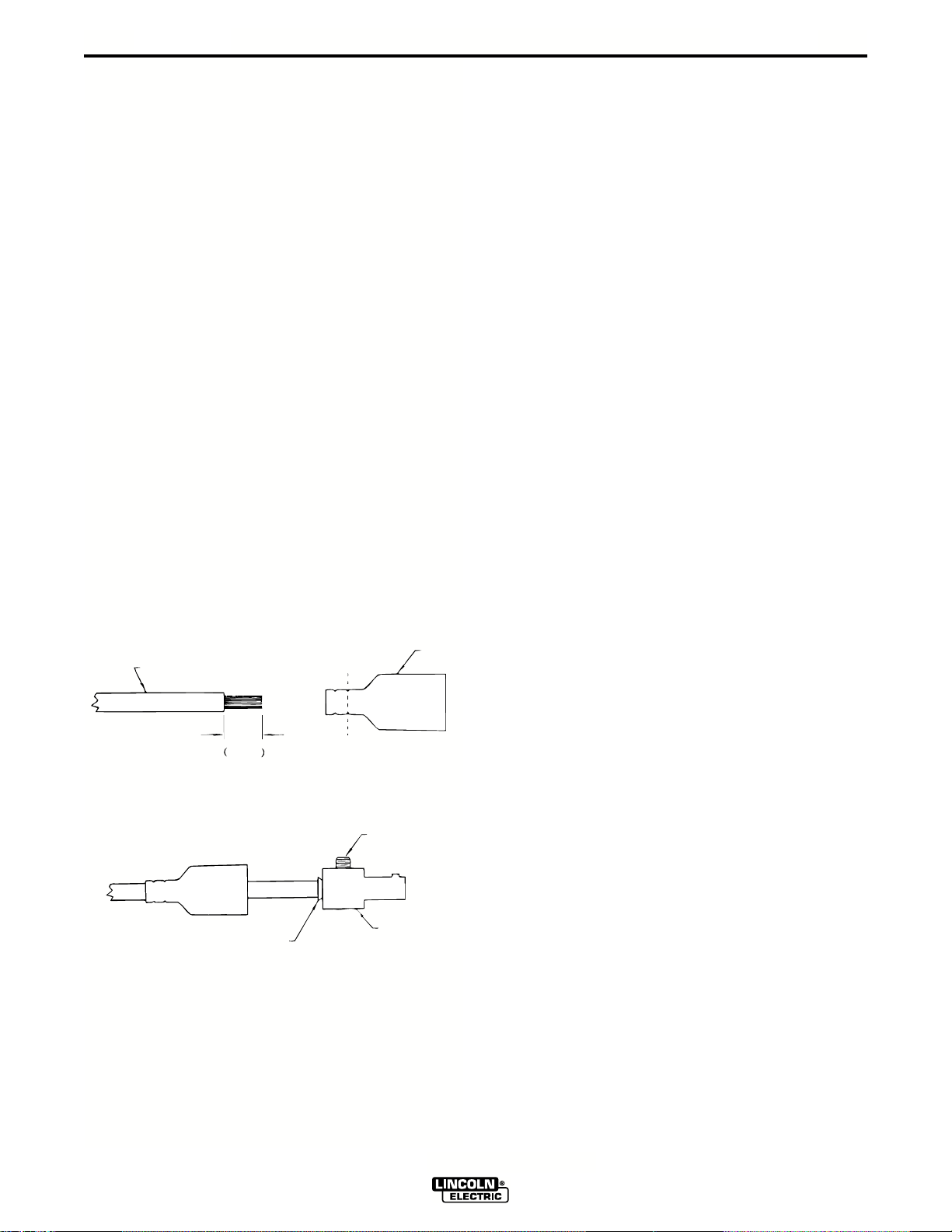
A-4
25 mm
1 in.
WELDING CABLE
BOOT
TRIM
SET SCREW
BRASS PLUG
COPPER TUBE
INSTALLATION
PARALLEL OPERATION
The V350-PRO (CE) are operable in parallel in CC
mode. For best results, the currents of each machine
should be reasonably well shared. As an example,
with two machines set up in parallel for a 400 amp
procedure, each machine should be set to deliver
approximately 200 amps, not 300 amps from one and
100 amps from the other. This will minimize nuisance
shutdown conditions. In general, more than two
machines in parallel will not be effective due to the
voltage requirements of procedures in that power
range.
To set machine outputs, start with output control pots
and arc control pots in identical positions. Use the
output control pots to balance the currents and maintain the desired voltage or current. The arc control
pots should be kept identical on the two machines.
QUICK DISCONNECT PLUGS
A quick disconnect system is used for the welding
cable connections. The welding plug included with the
machine is designed to accept a welding cable size of
1/0 to 2/0.
A-4
1. Remote 25mm (1 in.) of welding cable insulation.
2. Slide rubber boot onto cable end. The boot end
may be trimmed to match the cable diameter.
Soap or other lubricant will help to slide the boot
over the cable.
3. Slide the copper tube into the brass plug.
4. Insert cable into copper tube.
5. Tighten set screw to collapse copper tube. Screw
must apply pressure against welding cable. The
top of the set screw will be well below the surface
of the brass plug after tightening.
6. Slide rubber boot over brass plug. The rubber
boot must be positioned to completely cover all
electrical surfaces after the plug is locked into the
receptacle.
V350-PRO (CE)
Page 14
B-1
SAFETY PRECAUTIONS
OPERATION
OPERATIONAL FEATURES and CONTROLS:
B-1
WARNING
ELECTRIC SHOCK can kill.
• Do not touch electrically live parts or
electrode with skin or wet clothing.
• Insulate yourself from work and
ground.
• Always wear dry insulating gloves.
------------------------------------------------------------------------
FUMES AND GASES can be dangerous.
• Keep your head out of fumes.
• Use ventilation or exhaust to remove
fumes from breathing zone.
------------------------------------------------------------------------
WELDING SPARKS can cause fire or
explosion.
• Keep flammable material away.
• Do not weld on closed containers.
------------------------------------------------------------------------
ARC RAYS can burn eyes and skin.
• Wear eye, ear and body
protection.
------------------------------------------------------------
See additional warning information at
front of this operator’s manual.
-----------------------------------------------------------
GENERAL DESCRIPTION
PRODUCT DESCRIPTION & DUTY CYCLE
The Invertec V350-PRO (CE) offers multi mode CV
and CC DC welding and is rated at 350 amps, 34 volts
at a 60% duty cycle with 3 phase input. It is also rated
at 320 amps with single phase input. It is rated at 275
amps, 100% duty cycle.
UPPER CONTROL PANEL
1. AMPS Meter
• Prior to STICK or TIG operation (current flow), the
meter displays preset current value (either 2 amps
or +/- 3% (e.g. 3 amps on 100), whichever is
greater).
• Prior to CV operation, the meter displays four dashes indicating non-presettable AMPS.
• During welding, this meter displays actual average
amps.
• After welding, the meter holds the actual current
value for 5 seconds. Output adjustment while in the
"hold" period results in the "prior to operation" characteristics stated above. The displays blink indicating that the machine is in the "Hold" period.
2. VOLT METER
• Prior to CV operation (current flow), the meter displays desired preset voltage value (+/- .5V).
• Prior to STICK or TIG operation, the meter displays
the Open Circuit Voltage of the Power Source or
four dashes if the output has not been turned on.
• During welding, this meter displays actual average
volts.
• After welding, the meter holds the actual voltage
value for 5 seconds. The displays blink indicating
that the machine is in the "Hold" period.
• Output adjustment while in the "hold" period results
in the "prior to operation" characteristics stated
above.
3. OUTPUT CONTROL
• Output control is conducted via a single turn potentiometer.
• Adjustment is indicated by the meters as stated
above.
• When in TIG modes, this control sets the maximum
welding current. Full depression of a foot or hand
Amptrol results in the preset level of current.
4. WELD TERMINALS-REMOTE , ON
• Two status lights indicate the location of trigger control as determined by the "WELD TERMINALS"
push button.
• If trigger control is local "weld terminals on", the ON
display will be lit.
• If trigger control is remote "weld terminals remotely
controlled", the REMOTE display will be lit.
• The unit will power up in "pre-determined preferred"
trigger modes.
STICK = ON
TIG and CV = ON or REMOTE depending if remote
output controls are connected to the machine.
V350-PRO (CE)
Page 15
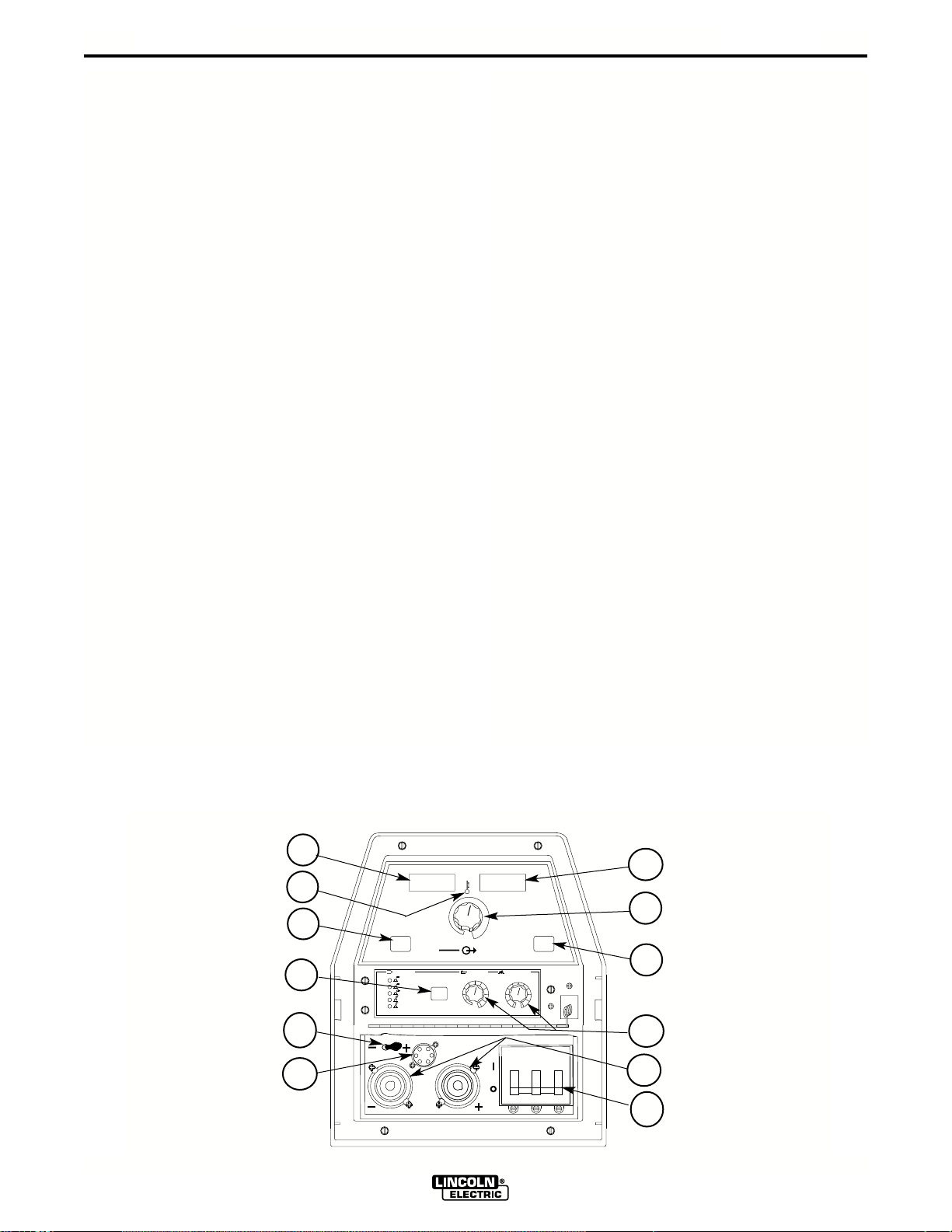
B-2
OFF
OFF OFF
OFF
ON
T STARART
WELD MODE
ARC CONTROLOL
CC-STICK SOFT
CC-STICK CRISP
TIG GTAW
-WIRE
-FLUX CORED
-4+4+4
+2
-2
0
-6
+6
-10
SOFT
CRISP
+10
-8
+8
5
4
3
2
1
0
6
10
9
8
7
SELECT
REMOTETE
ON
REMOTETE
LOCAL
WELD
TERMINALS
OUTPUT
CONTROL
SELECT
SELECT
MPS
A
OLTS
V
OPERATION
B-2
5. THERMAL
• This status light indicates when the power source
has been driven into thermal overload. If the output
terminals were "ON", the "ON" light will blink indicating that the output will be turned back on once the
unit cools down to an acceptable temperature level.
If the unit was operating in the "REMOTE" mode,
the trigger will need to be opened before or after the
thermal has cleared and closed after the machine
has cooled down to an acceptable temperature to
establish output.
6. CONTROL-REMOTE , LOCAL
• Two status lights indicate the location of output con-
trol as pre-determined by the power sources autoconfigure system.
• The LOCAL display will be lit when control is at the
power source.
• The REMOTE display will be lit when a remote
pot/control is detected.
These Output Control configurations can be overridden (switched) with the CONTROL push button.
When changed, the unit will power up in the configuration it was in when it was last powered down.
7. WELD MODE SELECT
The Mode Control button selects the following welding
modes desired.
CC-STICK SOFT: The Stick Soft process features
continuous control ranging from 5 to 425 amps. This
mode was intended for most SMAW applications, and
Arc Gouging.
• Arc Gouging: Setting the output of the Stick Soft
mode to 425 amps will enable the arc-gouging
mode. The actual output current will depend on the
size of carbon used. The recommended maximum
size carbon is 5/16".
• The Hot Start control regulates the starting current
at arc initiation. Hot Start can be adjusted from minimum (0), with no additional current added at arc
start, to maximum (10), with double the preset current or 425 amps (max of machine) added for the
first second after arc initiation.
• The Arc Control regulates the Arc Force to adjust
the short circuit current. The minimum setting (-10)
will produce a "soft" arc and will produce minimal
spatter. The maximum setting (+10) will produce a
"crisp" arc and will minimize electrode sticking.
Hidden Middle Control Panel – Process
Set Up Panel
The middle control panel is removable to allow for
upgrades (see Field Installed Options/Accessories).
Additionally, this panel is hidden by an access door to
reduce appeared complexity and provide protection to
the controls.
1
5
6
7
CONTR
SELECT
m
WELD MODE
CC-STICK SOFT
CC-STICK CRISP
TIG GT
CVCV-WIRE
CVCV-FLUX CORED
REMO
LOCAL
MPS
SELECT
11
CC-STICK CRISP: The Stick Crisp mode features
continuous control from 5 to 425 amps. This mode
was intended primarily for pipe welding applications.
• The Hot Start control regulates the starting current
at arc initiation. Hot Start can adjust starting current
up or down by 25% of the preset value. The recommended setting for Hot Start is 5 where the initial
current is equal to the preset current.
2
OL
3
WELD
TERMINALS
REMO
ON
OUTPUT
HOHOT ST
10
ARC CONTR
-10
SOFT
SELECT
+2
+6
+8
+10
CRISP
4
8
12
ON
OFF
V350-PRO (CE)
OFF
9
10
Page 16

B-3
OPERATION
B-3
• The Arc Control regulates the relative Slope of the
process. Slope dynamically controls the force the
arc has to penetrate an open root. At the minimum
setting, Arc Control is very soft and is similar to the
Stick Soft mode. At the maximum setting, the slope
is reduced, the OCV is reduced, and the operator
has full control off the arc force required to penetrate an open root joint. For vertical down, open root
pipe welding applications, the recommended setting
is between 8 and 10.
• During welding, a boost circuit increases the available voltage to minimize pop outs. The boost circuit
is independent of the OCV and only operates when
an arc is lit.
TIG GTAW: The TIG mode features continuous control from 5 to 425 amps. The TIG mode can be run in
either the TIG touch start or high frequency assisted
start mode.
• The Hot Start control selects the starting mode
desired. A setting of less than 5, the TIG lift start
mode is selected. The OCV is controlled below 10v
and the short circuit "TIG touch" current is maintained at 25 amps independent of the preset current.
When the tungsten is lifted, an arc is initiated and the
output is regulated at the preset value. Hot start settings between 0 and 5 regulate the arc initiation current. A setting of 5 results in the most positive arc initiation. A setting of 0 reduces hot start.
• Hot Start settings between 5 and 10, select high fre-
quency assisted starting TIG mode. In this range, the
OCV of the machine is controlled between 50 and 70
volts. If using the Lincoln K930-1 TIG Module, set
the Hot start to 10 for maximum OCV.
• The Arc Control is not used in the TIG mode.
CV-WIRE: The CV-WIRE mode features continuous
control from 10 to 45 volts. The mode was intended
for most GMAW, FCAW, and MCAW applications.
• The Hot Start control is not used in the CV-WIRE
mode.
• The Arc Control regulates pinch effect. At the minimum setting (-10), minimizes pinch and results in a
soft arc. Low pinch settings are preferable for welding with gas mixes containing mostly inert gases. At
the maximum setting (+10), maximizes pinch effect
and results in a crisp arc. High pinch settings are
preferable for welding FCAW and GMAW with CO2.
CV-INNERSHIELD: The CV-INNERSHIELD mode
features continuous control from 10 to 45 volts. This
mode was designed for self-shielded flux cored wires
that require tight voltage control.
• The Hot Start control is not used in the CV-FLUX
CORED mode.
• The Arc Control regulates pinch effect. At the minimum setting (-10), minimizes pinch and results in a
soft arc. At the maximum setting (+10), maximizes
pinch effect and results in a crisp arc. Most selfshielded wires work well at an Arc Control setting of 5.
8. HOT START and ARC CONTROL features have
different functions depending on the welding Mode
that is active. Each feature is described under the
welding mode heading. (See Item 6 for specified
Mode Operation)
LOWER CASE FRONT
The output studs, line switch and remote connector
are located on the lower case front.
9. Both STUDS contain "Twist-Mate" connector
inserts.
• The Negative stud is configured to accept the
pass through gas system.
10. The ON-OFF switch is a 3-phase circuit breaker
rated at 100 amps per leg.
11. The METER POLARITY switch is located above
the output connectors. The switch provides a work
connection for wire feeder voltmeters. Place the
switch in the position of the electrode polarity indicated by the decal. The switch does not change
the welding polarity.
12. 6-PIN AMPENOL for remote control.
REMOTE CONTROL of the OUTPUT CONTROL andWELD TERMINALS
The Invertec V350-PRO (CE) has auto sensing of
remote output controls.If after connecting or removing
a remote, the Invertec V350-PRO (CE) did not configured the way you would like the local or remote control settings can be changed by pushing the OUTPUT
CONTROL or WELD TERMINAL button. (A user cannot select between the 6 and 14 pin amphenols.)
CV modes
• The remote will default to the 14-pin amphenol
remote if a remote is connected to either of the 14pin amphenols and the 6-pin amphenol. Note: Only
one of the 14-pin amphenols can have a remote
control connected at a time. If no remote is connected to either of the 14-pin amphenols then the
remote will default to the 6-pin amphenol if a remote
is connected to it.
• If a remote control is connected or is not connect-
ed to any of the amphenols the WELD TERMINAL
control will default to REMOTE.
V350-PRO (CE)
Page 17

B-4
TIG mode
• The remote will default to the 6-pin amphenol if a
remote control is connected to the 6-pin amphenol
and one of the 14-pin amphenols. If a remote is not
connected to the 6-pin amphenol then the remote
will default to the 14-pin amphenols if a remote is
connected to one of the 14-pin amphenols.
• If a remote control is connected to any of the
amphenols the WELD TERMINAL control will
default to REMOTE. If there are not any remote
control devices attached the WELD TERMINAL control will default to ON.
CC-Stick modes
• The remote will default to only the 6-pin amphenol if
a remote is connected to it.
• The WELD TERMINAL control will default to ON
with or without a remote connected.
Types of Remote OUTPUT CONTROL
• The Invertec V350-PRO (CE)’s Output Control can
be controlled by either a potentiometer connected
between 77 & 75 with the wiper connected to 76 or
a 0V to 10V DC supply connected between 76 & 75.
(76 needs to be positive)
• 14-Pin Amphenol lead 75 is pin G, lead 76 is pin F
and lead 77 is pin E.
• 6-Pin Amphenol lead 75 is pin C, lead 76 is pin B
and lead 77 is pin A.
Potentiometer Control
• The total resistance should be between 2000 ohms
(2K) and 10,000 ohms (10K)
• The machine output will be at minimum when lead
76 (wiper) is at the end of the potentiometer that is
connected to 75. The machine’s output will increase
as the wiper of the potentiometer is moved to the
end that is connected to 77. (Note: In TIG mode,
moving the lead 76 (wiper) to lead 77 would produce the current that has been set by the Invertec
V350-PRO (CE)’s front panel Output Control.)
• Remotes of this type offered by Lincoln Electric are
the K857, K812 and K870.
Voltage Control
• The supply should be an isolated supply. (Not referenced to earth ground, any auxiliary power from the
Invertec V350-PRO (CE) or the welding output)
supply should be capable of supplying at least 20mA.
• 0 volts supplied to 76 will set the Invertec V350PRO (CE) to minimum output for the mode that has
been selected while 10 volts supplied to 76 will set
the Invertec V350-PRO (CE) to the maximum output
for the mode. (Note: In TIG mode, 10 volts supplied
to lead 76 would produce the current that has been
set by the Invertec V350-PRO (CE)’s front panel
Output Control.)
OPERATION
The
B-4
Types of Remote WELD TERMINAL Control
• The Invertec V350-PRO (CE)’s Weld Terminals can
be controlled from each of the amphenol connectors. The circuit has a nominal OCV of 15VDC and
requires a dry contact closure (less than 100 ohms)
to activate the output of the Invertec V350-PRO
(CE).
• 14 Pin Amphenols the Weld Terminals are controlled
from pins C (lead 2) and pin D (lead 4). Pin C is positive.
• 6 Pin Amphenol the Weld Terminals are controlled
from pin D (lead 2) and pin E (lead 4). In the 6-pin
amphenol pin D is positive.
DESIGN FEATURES and ADVANTAGES
• Multiple process DC output range: 5 - 425 amps
• Pre-settable welding outputs.
• Built-in Line Voltage Compensation holds the output
constant over +/- 10% input fluctuations.
• State of the art inverter technology yields high
power efficiency, excellent welding performance,
lightweight, and compact design.
• Utilizes microprocessor control.
• Electronic over current protection.
• Input over voltage protection
• Manual reconnect switch located on the back panel
with a clear reconnect door to allow easy determination of input configuration. The reconnect door is
fastened with 1/4-turn connectors that allow quick
and easy access to the reconnect area. Circuit
breaker protected auxiliary.
• System Self Configure. The power source analyzes
the remote controls connected to the amphenols
and the desired welding mode to properly determine
the location of trigger and output control.
• Modular options for easy upgrades
• Back lit Status Lights for improved error communi-
cation
• Circuit Breaker Input Switch
• F.A.N. (fan as needed). Cooling fan runs only when
necessary
• Thermostatically protected.
• Designed to the IEC 974-1 Standard.
• IP21S protection rating with potted PC boards for
enhanced ruggedness/reliability.
• Modular construction for easy servicing.
• Aluminum Chassis and Wraparound
• Power Cord included.
V350-PRO (CE)
Page 18

B-5
AUXILIARY POWER
• 115VAC, 42VAC and 24VAC power is available
from the two 14-pin amphenols on the rear of the
unit. (K1728-2 Construction model of the Invertec
V350-PRO (CE) does not have the amphenols)
These supplies are intended to supply power for
auxiliary equipment like wire feeders and the TIG
Module.
• 115VAC supply is rated at 2 amps and is protected
by a 2.5 amp breaker located by the amphenol.
• 42 VAC supply is rated at 5.5 amps and is protected
by a 6 amp breaker located by the amphenol.
• 24 VAC supply is rated at 5.5 amps and is protected
by a 6 amp breaker located by the amphenol.
LIMITATIONS
• The V350-PRO (CE) is not recommended for
processes other than those listed.
• The V350-PRO (CE) can only be used with the recommended equipment and options.
RECOMMENDED PROCESSES
Properly equipped, the Invertec V350-PRO (CE)
supports GMAW, FCAW, SMAW, GTAW and CACA processes for a variety of materials, including
mild steel, stainless steel, cored wires, and aluminum
OPERATION
B-5
V350-PRO (CE)
Page 19

C-1
ACCESSORIES
OPTIONS / ACCESSORIES
"CE" VERSION – K1728-3
• The "CE" version is the Factory version with the
addition of power line filtering allowing the machine
to comply with the European and Australian EMC
emission requirements.
• In this form, the V350-PRO (CE) provides the hardware to
feeders.
K857 Remote Output Control
K814 Arc Start Switch
K812 Hand Operated Amptrol
K870 Foot Operated Amptrol
K930-1 TIG Module
K428, K446, K449 LN-25
K617 (-1 or -2) K618 (-1 or -2) LN-742
K440 (-1), K567-1 LN-7 GMA
K1559-1, K1564-1 LN-10
K1499-1, K1521-1 DH-10
power and connect to 24, 42 or 115 VAC wire
C-1
FIELD INSTALLED OPTIONS/ACCESSORIES
Options for K1728-1 Factory and K1728-3 "CE"
V350’s
• TIG Gas Control Kit – K1762-1
• Advance Process Panel – K1763-1
• Undercarriage – K1764-1
• Valet Style Undercarriage – K1838-1
V350-PR0 (CE)
Page 20
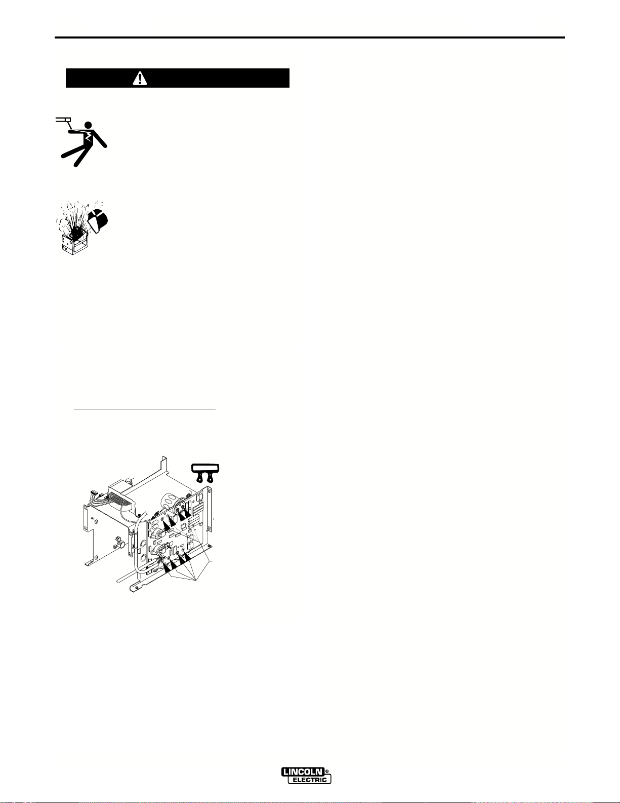
D-1
CAPACITOR
TERMINALS
RESISTOR
MAINTENANCE
D-1
SAFETY PRECAUTIONS
WARNING
----------------------------------------------------------------------
-
ELECTRIC SHOCK can kill.
• Do not touch electrically live parts or
electrode with skin or wet clothing.
• Insulate yourself from work and
ground
• Always wear dry insulating gloves.
------------------------------------------------------------------------
EXPLODING PARTS can cause
injury.
•
Failed parts can explode or cause other
parts to explode when power is applied.
•
Always wear a face shield and long
sleeves when servicing.
------------------------------------------------------------------------
See additional warning information
throughout this operator’s manual and
the Engine manual as well.
-----------------------------------------------------------
CAPACITOR DISCHARGE PROCEDURE
1. Obtain a power resistor (25 ohms, 25 watts).
2. Hold resistor body with electrically insulated glove.
DO
NOT TOUCH TERMINALS. Connect the resistor terminals across the two studs in the position
shown. Hold in each position for 1 second. Repeat
for all four capacitors.
VISUAL INSPECTION
Clean interior of machine with a low pressure air
stream. Make a thorough inspection of all components. Look for signs of overheating, broken leads or
other obvious problems. Many problems can be
uncovered with a good visual inspection.
ROUTINE MAINTENANCE
1. Every 6 months or so the machine should be
cleaned with a low pressure airstream. Keeping
the machine clean will result in cooler operation
and higher reliability. Be sure to clean these areas:
• All printed circuit boards
• Power switch
• Main transformer
• Input rectifier
• Auxiliary Transformer
• Reconnect Switch Area
2. Examine the sheet metal case for dents or breakage.
Repair the case as required. Keep the case in good condition to insure that high voltage parts are protected and
correct spacings are maintained. All external sheet
metal screws must be in place to insure case strength
and electrical ground continuity.
PERIODIC MAINTENANCE
Overload Protection
The machine is electrically protected from producing
high output currents. Should the output current
exceed 430A, an electronic protection circuit will
reduce the current to approximately 100A. The
machine will continue to produce this low current until
the protection circuit is reset. Reset occurs when the
output load is removed.
3. Use a DC voltmeter to check that voltage is not
present across the terminals on all four capacitors.
V350-PRO (CE)
Thermal Protection
Thermostats protect the machine from excessive
operating temperatures. Excessive temperatures may
be caused by a lack of cooling air or operating the
machine beyond the duty cycle and output rating. If
excessive operating temperature should occur, the
thermostat will prevent output voltage or current. The
meter will remain energized during this time.
Thermostats are self-resetting once the machine cools
sufficiently. If the thermostat shutdown was caused by
excessive output or duty cycle and the fan is operating
normally, the Power Switch may be left on and the
reset should occur within a 15 minute period.
Page 21

E-1
TROUBLESHOOTING
HOW TO USE TROUBLESHOO TING GUIDE
WARNING
Service and Repair should only be performed by Lincoln Electric Factory Trained Personnel.
Unauthorized repairs performed on this equipment may result in danger to the technician and
machine operator and will invalidate your factory warranty. For your safety and to avoid Electrical
Shock, please observe all safety notes and precautions detailed throughout this manual.
__________________________________________________________________________
E-1
This Troubleshooting Guide is provided to help you
locate and repair possible machine malfunctions.
Simply follow the three-step procedure listed below.
Step 1. LOCATE PROBLEM (SYMPTOM).
Look under the column labeled “PROBLEM (SYMPTOMS)”. This column describes possible symptoms
that the machine may exhibit. Find the listing that
best describes the symptom that the machine is
exhibiting.
Step 2. POSSIBLE CAUSE.
The second column labeled “POSSIBLE CAUSE” lists
the obvious external possibilities that may contribute
to the machine symptom.
Step 3. RECOMMENDED COURSE OF ACTION
This column provides a course of action for the
Possible Cause, generally it states to contact your
local Lincoln Authorized Field Service Facility.
If you do not understand or are unable to perform the
Recommended Course of Action safely, contact your
local Lincoln Authorized Field Service Facility.
CAUTION
If for any reason you do not understand the test procedures or are unable to perform the tests/repairs safely, contact your
Local Lincoln Authorized Field Service Facility for technical troubleshooting assistance before you proceed.
V350-PRO (CE)
Page 22
E-2
PROBLEMS
(SYMPTOMS)
TROUBLESHOOTING
Observe all Safety Guidelines detailed throughout this manual
POSSIBLE AREAS OF
MISADJUSTMENT(S)
RECOMMENDED
COURSE OF ACTION
E-2
Major physical or electrical damage
is evident when the sheet metal
covers are removed.
Input fuses keep blowing, or input
breaker keeps tripping
Machine will not power up (No
lights)
1. Contact your local authorized
Lincoln Electric Field Service
facility for technical assistance.
1. Make certain that the fuses or
breakers are properly sized. See
installation section of the manual
for recommended fuse and
breaker sizes.
2. Welding procedure is drawing too
much output current, or duty
cycle is too high. Reduce output
current, duty cycle or both.
3. There is internal damage to the
power source. Contact an authorized Lincoln Electric Service
facility.
1. Make certain that the power
switch is in the "ON" position.
2. The circuit breaker in the reconnect area may have opened.
Reset. Check input voltage section below.
3. Input voltage selection made
improperly. Power down, check
input voltage reconnect according to diagram on reconnect
cover.
I
f all recommended possible areas
of misadjustment have been
checked and the problem persists,
Contact your local Lincoln
Authorized Field Service Facility.
Machine won’t weld, can’t get any
output.
1. If the displays show an Err ###
see the fault section for corrective action.
2. If the displays are not lit refer to
machine will not power up section.
3. If the thermal symbol is lit refer to
the thermal section.
4. If the output terminals are in
Remote control switch to "ON"
and check for output voltage. If
output voltage is now present
check for correct remote control
connection and operation.
CAUTION
If for any reason you do not understand the test procedures or are unable to perform the tests/repairs safely, contact your
Local Lincoln Authorized Field Service Facility for technical troubleshooting assistance before you proceed.
V350-PRO (CE)
Page 23
E-3
PROBLEMS
(SYMPTOMS)
TROUBLESHOOTING
Observe all Safety Guidelines detailed throughout this manual
POSSIBLE AREAS OF
MISADJUSTMENT(S)
RECOMMENDED
COURSE OF ACTION
E-3
Thermal symbol is lit
Wire feeder won’t work. Apparently
no power to wire feeder
1. Check for proper fan operation
2. Check for material blocking
intake or exhaust louvers.
1. Check circuit breakers by the
wire feeder receptacles on the
rear of the machine. Reset
2. Check to make sure the wire
feeder is connected to the correct
wire feeder receptacle. (115VAC
or 24/42VAC)
3. Check the control cable between
the power source and the wire
feeder for continuity.
I
f all recommended possible areas
of misadjustment have been
checked and the problem persists,
Contact your local Lincoln
Authorized Field Service Facility.
CAUTION
If for any reason you do not understand the test procedures or are unable to perform the tests/repairs safely, contact your
Local Lincoln Authorized Field Service Facility for technical troubleshooting assistance before you proceed.
V350-PRO (CE)
Page 24
E-4
TROUBLESHOOTING
Observe all Safety Guidelines detailed throughout this manual
E-4
Fault Codes
Code Description Corrective Action
31 Primary over current. If condition persists The machine needs to
contact an authorized be turned off and back
Lincoln Field Service
on to reset the machine.
Shop
32 CAP bank A under voltage. Check input power Self-clearing as
33 CAP bank B under voltage. reconnect to make sure condition ceases.
34 CAP bank A over voltage. the machine
35 CAP bank B over voltage. is connected for the input
37 Soft start Failed. power being supplied. Cycle power.
39 Glitch on the primary over Check the machine Self-clearing as
current fault interrupt; possibly ground. condition ceases.
caused by noise or a signal level If problem persists
(misc. hardware fault #1) contact an authorized
Lincoln Field Service
Shop
43 CAP delta; CAP A and B are out Check input power
of balance. reconnect to make sure
the machine is
connected for the input
power being supplied.
44 Main CPU problem. The DSP Check the machine
has detected a problem with the ground.
CPU.
47 Glitch on the CAP/heart beat If problem persists
interrupt; possibly caused by contact an authorized
noise or a signal level right at Lincoln Field Service
the trip threshold. Shop
(misc. hardware fault #2)
48 The main contactor opened If condition persist Self-clearing
unexpectedly. (misc. hardware contact an authorized
fault #3) Lincoln Field Service
Shop
"bad The selected weld mode does If condition persists Press the Mode
node’ not exist in the weld table that is contact an authorized Select button to
“####”
presently loaded in the machine. Lincoln Field Service select a different
Shop mode
CAUTION
If for any reason you do not understand the test procedures or are unable to perform the tests/repairs safely, contact your
Local Lincoln Authorized Field Service Facility for technical troubleshooting assistance before you proceed.
V350-PRO (CE)
Page 25
E-5
Observe all Safety Guidelines detailed throughout this manual
TROUBLESHOOTING
Displays Description
E-5
Scrolling dash
Appears at power up while the machine is going through its self configuration
"Err" "####" Fault code display. The first fault to occur will be displayed for three
seconds. The display will cycle through fault codes for all faults that
persist after the initial three-second period are displayed for 1 sec-
ond each.
"----" "----" Weld mode is changing
"----" "####" A constant voltage weld mode is selected, machine output is off.
The numeric value in the right display is the workpoint.
"####" "----" A constant current weld mode is selected, machine output is off.
The numeric value in the left display is either the workpoint or a
workpoint limit, depending on the weld mode and remote configura-
tion.
"####" "####"(on steady) machine output is on. Left display is current, right display is voltage.
If actively welding, the displays are arc current and arc voltage. If
not actively welding, the display will show workpoint.
"####" "####" (blinking) weld just finished – the average arc voltage and current will be
blinked for 5 seconds following a weld. If the workpoint changes dur-
ing this 5 second period, the display will revert to the above mode.
CAUTION
If for any reason you do not understand the test procedures or are unable to perform the tests/repairs safely, contact your
Local Lincoln Authorized Field Service Facility for technical troubleshooting assistance before you proceed.
V350-PRO (CE)
Page 26
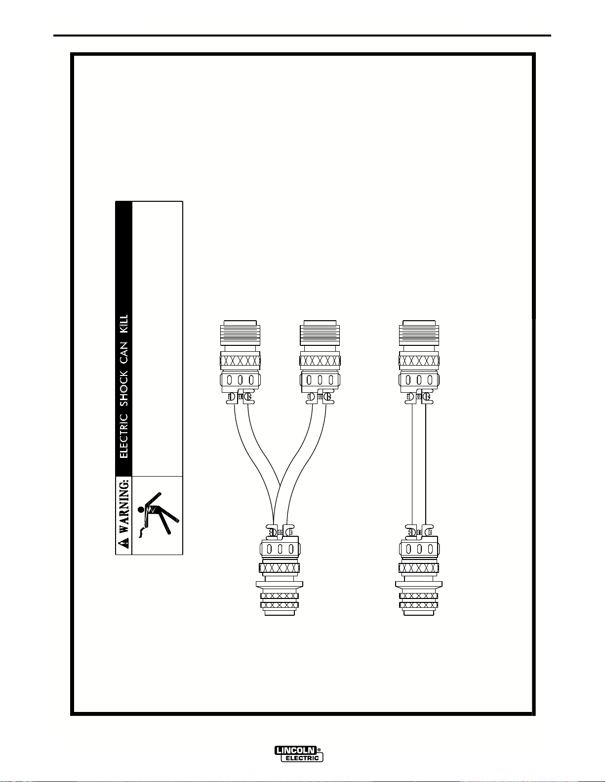
F-1
DIAGRAMS
2) K963 HAND AMPTROL
3) K870 FOOT AMPTROL
TO: 1) K857 REMOTE CONTROL
CABLE RECEPTACLE (6 SOCKET)
TO: 1) LN-7 WIRE FEEDERS
CABLE RECEPTACLE (14 SOCKET)
F-1
S19309
4-19-96D
TO: 1) LN-25 WIRE FEEDERS
CABLE RECEPTACLE (6 SOCKET)
TURN THE POWER SWITCH OF THE WELDING POWER
SOURCE "OFF" BEFORE INSTALLING PLUGS ON CABLES
OR WHEN CONNECTING OR DISCONNECTING PLUGS TO
WELDING POWER SOURCE.
REMOTE CONTROL ADAPTERS
STRAIGHT PLUG (14 PIN)
TO POWER SOURCE
K864
V350-PRO (CE)
STRAIGHT PLUG (14 PIN)
TO POWER SOURCE
K876
Page 27
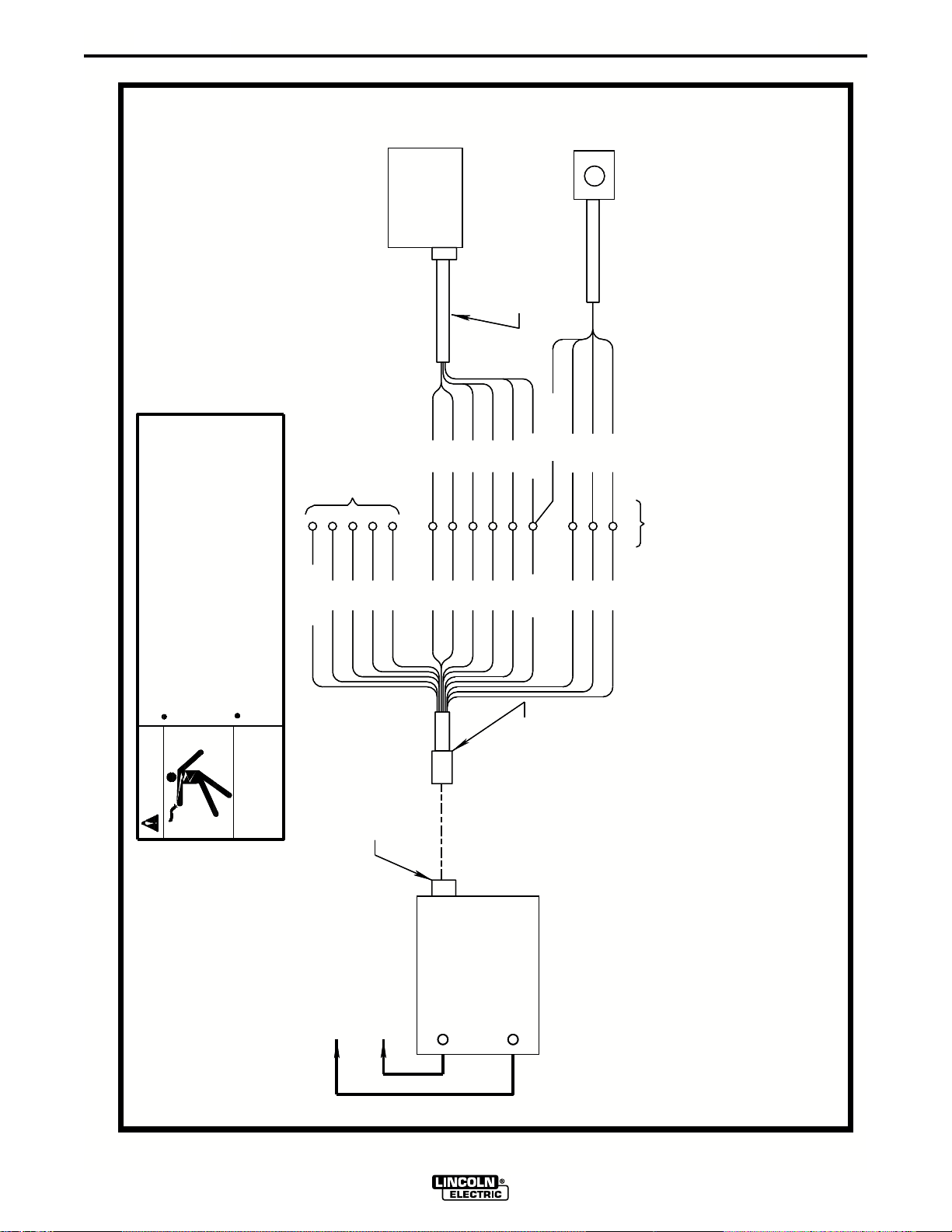
F-2
S19404
S19404
LN-7
CONTROL
BOX
LN-7
CONTROL
BOX
N.C.
N.C.
DIAGRAMS
K291 OR K404
K291 OR K404
2
4
2
32
32
4
21
21
31
31
INPUT CABLE
INPUT CABLE
GREEN
GREEN
757677
757677
GND
GND
K775 OPTIONAL
REMOTE CONTROL
K775 OPTIONAL
REMOTE CONTROL
F-2
12-10-93A
2
4
2
828142
828142
SPARE
SPARE
service this machine.
service this machine.
Only qualified persons should install, use or
Only qualified persons should install, use or
Before connecting the wire feeder.
Before connecting the wire feeder.
using the disconnect switch at the fuse box
using the disconnect switch at the fuse box
Turn off input power to the Welding Power Source
Turn off input power to the Welding Power Source
SHOCK
SHOCK
ELECTRIC
ELECTRIC
CAN KILL
WARNING
WARNING
CAN KILL
41
41
14 PIN
AMPHENOL
14 PIN
AMPHENOL
31
31
32
32
4
K867 PLUG TO LN-7 - CONNECTION DIAGRAM
21
21
K867 UNIVERSAL
K867 UNIVERSAL
757677
757677
GND
GND
ADAPTER PLUG
ADAPTER PLUG
N.D.
N.D.
-
TO
WORK
TO
ELECTRODE CABLE
ELECTRODE CABLE
WORK
TO LN-7
TO LN-7
-
V350-PRO (CE)
+
+
AUXILIARY POWER
POWER SOURCE
POWER SOURCE
INVERTEC
INVERTEC
AUXILIARY POWER
WITH 115VAC
WITH 115VAC
N.D. SPLICE LEADS AND INSULATE.
N.A. WELDING CABLE MUST BE SIZED FOR CURRENT AND DUTY CYCLE OF APPLICATION.
N.B. DIAGRAM SHOWS ELECTRODE POSITIVE. TO CHANGE POLARITY, TURN POWER "OFF",
N.A. WELDING CABLE MUST BE SIZED FOR CURRENT AND DUTY CYCLE OF APPLICATION.
REVERSE ELECTRODE AND WORK CABLE AT POWER SOURCE.
N.B. DIAGRAM SHOWS ELECTRODE POSITIVE. TO CHANGE POLARITY, TURN POWER "OFF",
REVERSE ELECTRODE AND WORK CABLE AT POWER SOURCE.
N.D. SPLICE LEADS AND INSULATE.
N.C. INSULATE EACH UNUSED LEAD INDIVIDUALLY.
N.C. INSULATE EACH UNUSED LEAD INDIVIDUALLY.
Page 28
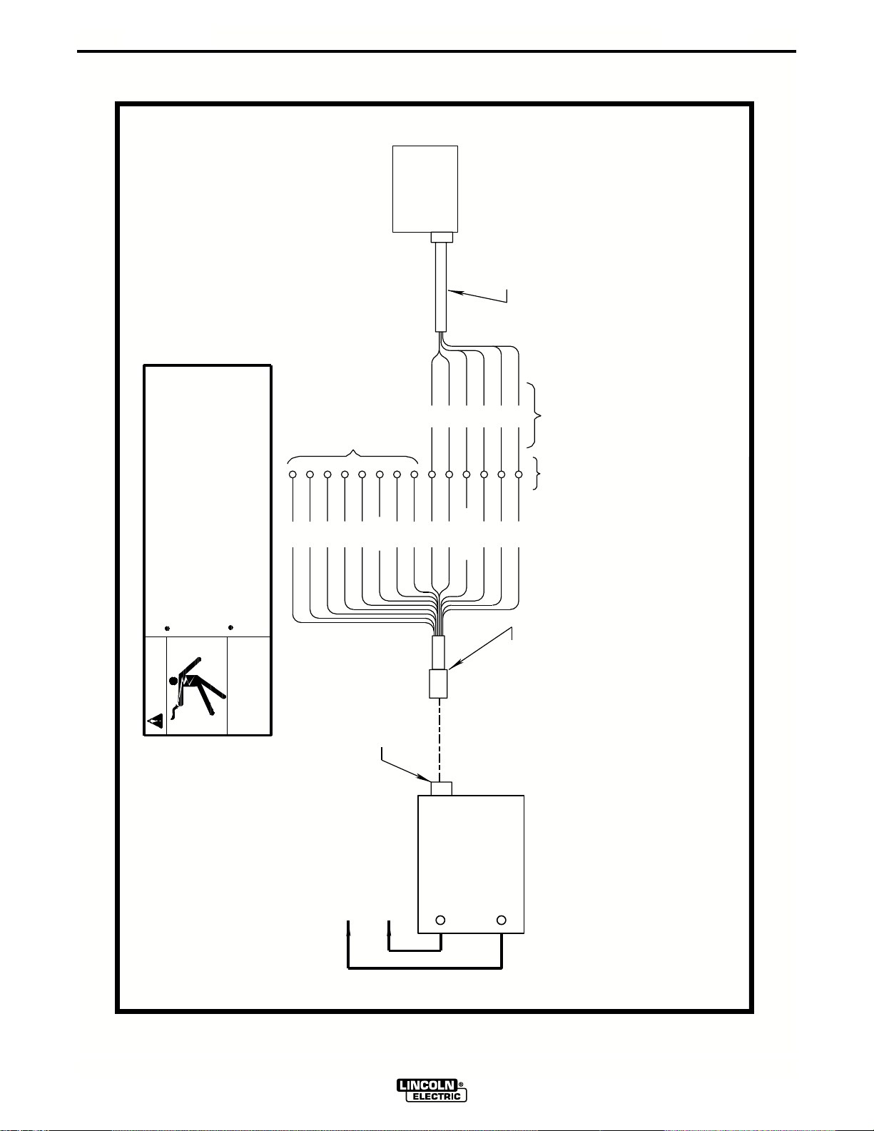
F-3
DIAGRAMS
LN-25 WITH
K431 OPTION
E
N.C.
F-3
S19405
1-25-91
K432 REMOTE
CONTROL CABLE
B
D
F
C77
A
N.D.
2
2182814241
service this machine.
Only qualified persons should install, use or
Before connecting the wire feeder.
using the disconnect switch at the fuse box
Turn off input power to the Welding Power Source
SHOCK
ELECTRIC
WARNING
CAN KILL
31
GND
14 PIN
AMPHENOL
32
4
SPARE
K867 PLUG TO LN-25 - CONNECTION DIAGRAM
75
76
K867 ADAPTER
N.E.
WORK
-
TO
ELECTRODE CABLE
TO LN-25
V350-PRO (CE)
+
INVERTEC
POWER SOURCE
N.A. WELDING CABLE MUST BE SIZED FOR CURRENT AND DUTY CYCLE OF APPLICATION.
N.B. DIAGRAM SHOWS ELECTRODE POSITIVE. TO CHANGE POLARITY, TURN POWER "OFF",
REVERSE ELECTRODE AND WORK CABLE AT POWER SOURCE.
N.C. INSULATE EACH UNUSED LEAD INDIVIDUALLY.
N.D. REMOVE 6 PIN PLUG FROM K432 CABLE IN ORDER TO CONNECT K867 PLUG.
LABEL EACH LEAD (A THRU F) AS THEY ARE REMOVED FROM 6 PIN PLUG.
N.E. SPLICE LEADS AND INSULATE.
Page 29
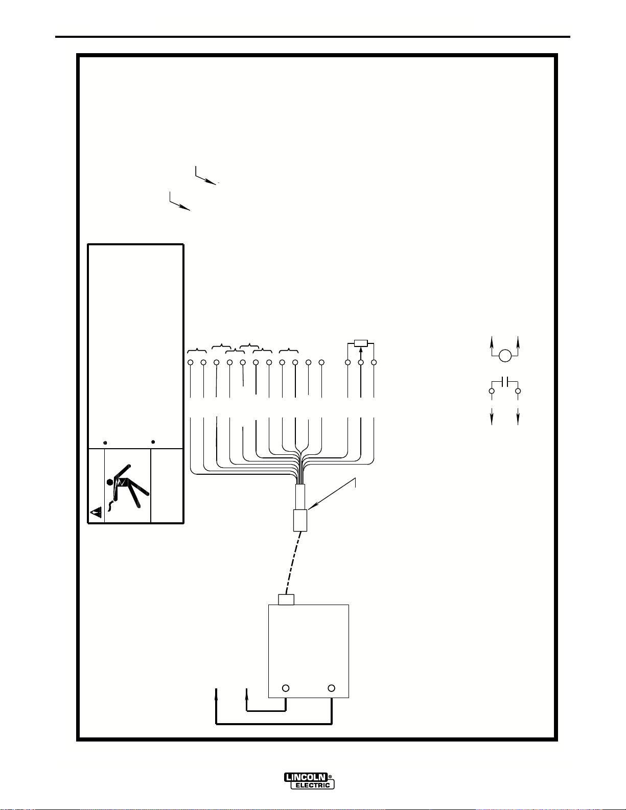
F-4
N.C.
N.D.
DIAGRAMS
REMOTE OUTPUT CONTROL
F-4
3-1-00
S24985
NOT USED ON INVERTEC
CONNECT TOGETHER FOR WELDING OUTPUT
24 VAC / 5.5 AMP
2
4
82
81
service this machine.
Only qualified persons should install, use or
Before connecting the wire feeder.
using the disconnect switch at the fuse box
Turn off input power to the Welding Power Source
SHOCK
ELECTRIC
WARNING
CAN KILL
24 VAC / 5.5 AMP
41
SPARE
14 PIN
115 VAC / 2 AMP
42 VAC / 5.5 AMP
42
INVERTEC FRAME CONNECTION
31
32
GND
AMPHENOL
TO
MIN.
10K
WIRE FEEDER VOLTMETER CONNECTION
CONNECTS TO (WORK TERMINAL) OF INVERTEC
21
77
76
75
K867 UNIVERSAL
ADAPTER PLUG
WIRE FEEDER
2
4
TO
K867
K867 UNIVERSAL ADAPTER / INVERTEC - CONNECTION DIAGRAM
WORK
-
TO
ELECTRODE CABLE
V350-PRO (CE)
+
INVERTEC
POWER SOURCE
WITH 115VAC
N.A. WELDING CABLE MUST BE SIZED FOR CURRENT AND DUTY CYCLE OF APPLICATION.
AUXILIARY POWER
N.B. DIAGRAM SHOWS ELECTRODE POSITIVE. TO CHANGE POLARITY, TURN POWER "OFF",
REVERSE ELECTRODE AND WORK CABLE AT POWER SOURCE.
N.D. FOR WIRE FEEDERS THAT RETURN A SIGNAL FOR WELDING OUTPUT, USE ISOLATION
RELAY TO CLOSE LEADS 2 & 4.
N.C. INSULATE EACH UNUSED LEAD INDIVIDUALLY.
Page 30
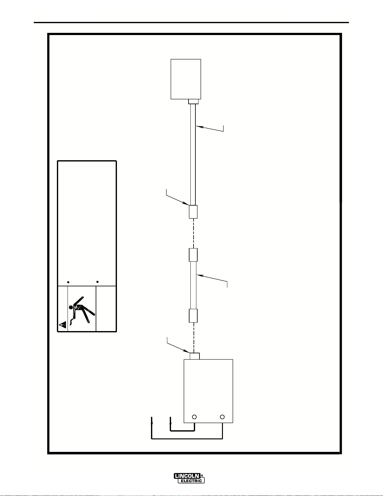
F-5
DIAGRAMS
LN-25 WITH
K431 OPTION
6 PIN
AMPHENOL
K432 REMOTE
CONTROL CABLE
F-5
1-25-91
S19899
service this machine.
Only qualified persons should install, use or
Before connecting the wire feeder.
using the disconnect switch at the fuse box
Turn off input power to the Welding Power Source
SHOCK
ELECTRIC
WARNING
CAN KILL
14 PIN
AMPHENOL
K876 ADAPTER
K876 ADAPTER TO LN-25 - CONNECTION DIAGRAM
WORK
-
TO
ELECTRODE CABLE
TO LN-25
+
INVERTEC
POWER SOURCE
N.A. WELDING CABLE MUST BE SIZED FOR CURRENT AND DUTY CYCLE OF APPLICATION.
N.B. DIAGRAM SHOWS ELECTRODE POSITIVE. TO CHANGE POLARITY, TURN POWER "OFF",
REVERSE ELECTRODE AND WORK CABLE AT POWER SOURCE.
N.C. FOR INVERTECS WITH 6 PIN AMPHENOL, K432 CABLE CAN BE CONNECTED DIRECTLY.
V350-PRO (CE)
Page 31
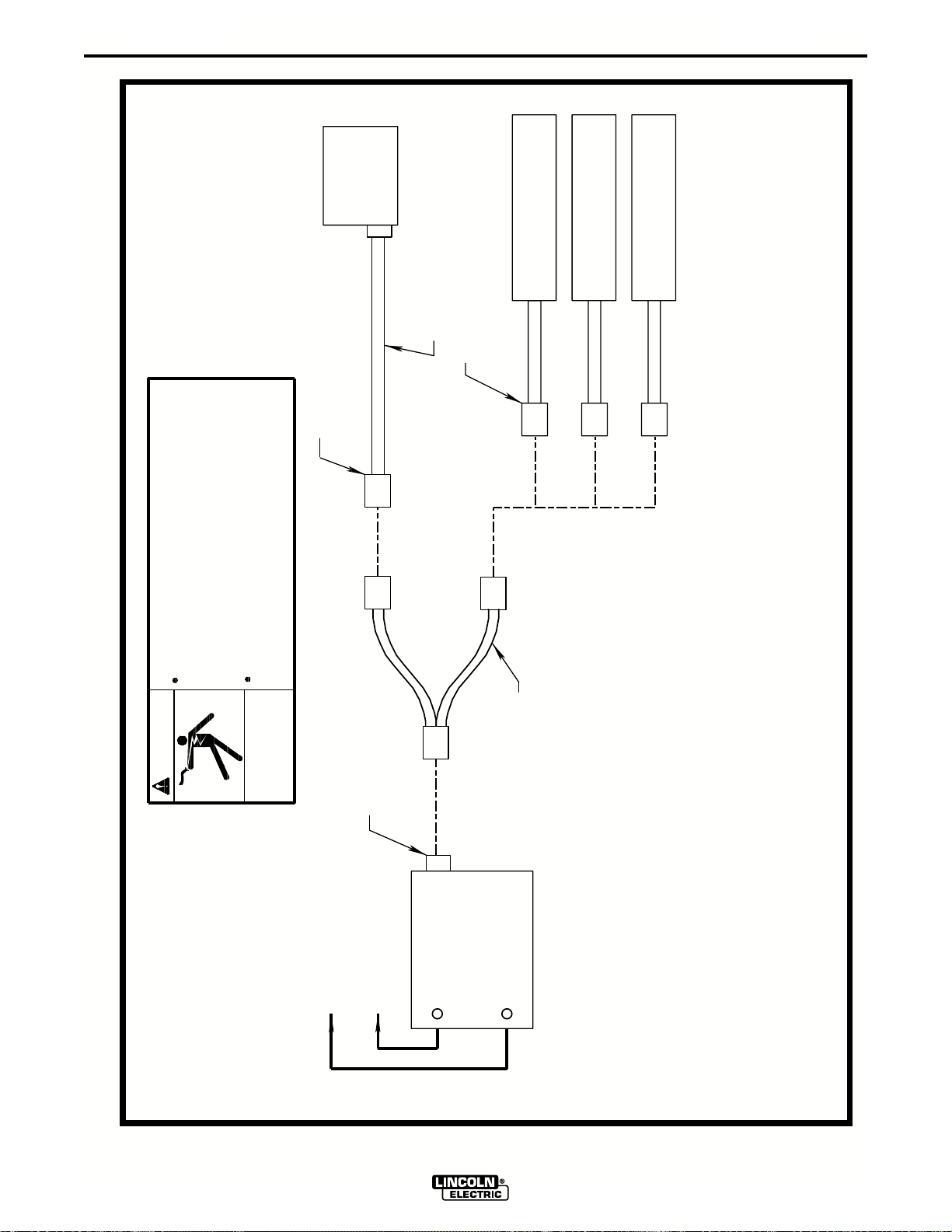
F-6
LN-7
CONTROL
BOX
14 PIN
AMPHENOL
DIAGRAMS
K857
K480-7 INPUT CABLE
6 PIN
AMPHENOL
REMOTE CONTROL
K963
HAND AMPTROL
K870
FOOT AMPTROL
OR
OR
F-6
4-19-96D
S19901
service this machine.
Only qualified persons should install, use or
Before connecting the wire feeder.
using the disconnect switch at the fuse box
Turn off input power to the Welding Power Source
ADAPTER
K864
WARNING
SHOCK
ELECTRIC
CAN KILL
14 PIN
AMPHENOL
K864 ADAPTER TO LN-7 & REMOTE CONTROL - CONNECTION DIAGRAM
WORK
-
TO
ELECTRODE CABLE
TO LN-7
+
INVERTEC
AUXILIARY POWER
WITH 115VAC
POWER SOURCE
N.A. WELDING CABLE MUST BE SIZED FOR CURRENT AND DUTY CYCLE OF APPLICATION.
N.C. K480-7 INPUT CABLE CAN BE CONNECTED DIRECTLY IF REMOTE CONTROL IS NOT REQUIRED.
N.B. DIAGRAM SHOWS ELECTRODE POSITIVE. TO CHANGE POLARITY, TURN POWER "OFF",
REVERSE ELECTRODE AND WORK CABLE AT POWER SOURCE.
N.D. K864 ADAPTER CANNOT BE USED WITH AN LN-25.
V350-PRO (CE)
Page 32
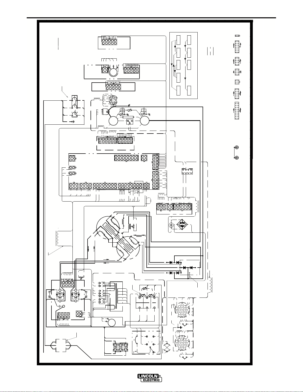
F-7
ENHANCED DIAGRAM
RIGHT SIDE OF MACHINE
WIRING DIAGRAM INVERTEC V350-PRO (CE)
}
INPUT
PER
DIAGRAMS
E
A
CH
IN
F M
O
FR
NT
O
1
2
J10A,
6498327
1
510
STATU
6
5
2
1
802
801
806
201
C2,C4
+
FAN
115V
COM2
FAN
2
4
1
6
CURRENT
TRANSDUCER
4A
J331
J7
16
15
715
716
205
541
24
42
31
532
41A
54
P56
PRIMARY
J37
275
277
276
3
24
1
J311
S
105
J34
75
2A
2
76
4
77
8
0
1
8
0
8
0
J90
32
8
0
4
4
2
77
75
76
12
11
5
6
410
REMOT
B
N
RI-I
P
UT
RI-O
P
6
I
P52
16
7
5
11
1
6
1
FAN
FAN
RECONNECT
DISPLAY
POT
CONTROL
277
275
276
J31
R5
10K/2W
72
6
94
MOD
38
1
75A
77A
+
C
D
EFAB
+
W )
E
VI
AR
E
6 PIN
(R
REMOTE
TP4
901B
R1
901A
901
553
76A
551
552
554
93
7
28
1
5101649
J33
E
J1
J6
15
16
7
8
607
608
615
616
X2
X20
L1
T
OS
BO
C
SE
REACTOR
X30
X3
X
1
2
7
3
N
PRI-O UT
204
208
COM1
24V
AUXILIARY
28V
H6
42V
H5
H4
H3
H2
COM2A
H1
COM2
115V
FAN
207A
203
206
E
H
IN
61
73894
10
2
5
E
TP5
903B
903A
S1
21
21B
8
3
27
CONTROL
1011121314
2
5
3
4
6
605
611
602
610
612
609
X30
506
503
xxxxxxx
CHOKE
X10
T
OS
BO
C
SE
A
RI-I
P
XFMR
MAIN
N.E.
XFMR
A
INPUT
BRIDGE
AA
2A
202
CB2
( 380-575VAC POSITION )
N.C.
AC
O
F M
R
E
AR
_
903
1
6
78
2
J2
9
1
L2
X40
X4
TP3
A
+
209
3
9
4
5
10
J3
7
4
0
1
7
1
8
4
0
2
J4
2
4
0
3
389
0
46
J5
10
1
4
0
5
5
3
4
1112
2
4
0
2
502
6
1
503
506
411
410
412
407
2
505
5
41
J42
REACTOR
TP1
A
D
200-
H2
380-
H4
CONTROL
X10
C
B
H1
TP2
C
B
_
_
F
E
207
207A
220-
230V
H3
415V 208V
440-
460V
H5
550-
575V
H6
LOR CODE:
N = BROWN
U = BLUE
Y = YELLOW
W = WHITE
R = RED
G = GREEN
B = BLACK
CO
IN PARANT HESYS COLORS
FOR CE MACHINES
CB1
BREAKER
100 A CIRCUIT
A
B(U)
U
B
R(B)
V
C
W(N)
W
G(G/Y)
J11
1
2
1010
10201002
J10B
2
1
1001
J10A
J9
J8
7
8
5
6
4
2
3
3
1
4
901
903
804
1001,1002,
1010,1020
502
610
608
605
1020
1010
786
3
4
208
J21
C1,C3
3200/300
+
206 203
205
209
2
3
1
SWITCH
J20
7
84
6
5
716
715
602
611
609
612
615
607
505
616
1001
1002
xxxxxxx
5
2
1
201
207
3200/300
202
204
4
J22
12
3
N.D.
N.A.
IT
CU
R
CI
EX
I FL
SP
IT
CU
R
CI
EX
I FL
SP
IT
CU
R
CI
EX
I FL
SP
IT
CU
R
CI
EX
I FL
SP
4
0
4
0
4
1
4
1
4
1
408
65
66
3
132
6
4
J41
65
+
C5
2400/80
66
RECTIFIER
OUTPUT
RECTIFIER
X2
X4
GAS
SOLENOID
553
+
554
438
431
432
1
7
J43
41A
31
32
J
A
GND
42
J
A
GND
DISPLAY
STATUS
MODE
FOR MACHINES WITH REMOTE BOARD
REMOTE
CONTROL
552
551
2
1
3
P55
438
431
401
405
406
403
432
5
4
3
2
8
9
11
10
POWER
+
65B
~
~
-
66B
SNUBBER
X20
X30
X40
21
75A
H
I
G
F
N
K
M
L
E
D
B
C
4A
4B
2B
2A
GND
32
CB2
41
21B
24
75B
41B
H
I
G
F
N
K
M
L
E
B
D
C
4B
2B
41B
6A 2A
41
CB1
DISPLAY
LEGEND
ALL MACHINES
OPTION
COMPONENT OUTLINE
FOR MACHINES WITHOUT REMOTE BOARD
SPI FLEX CIRCUIT CONNECTION DETAIL
CONTROL MODE STATUS
ON "CE" MODELS.
N.D. INPUT POWER LINE FILTER IS PRESENT ONLY
4
402
6
12
54
X10
LEFT SIDE OF MACHINE
21,21B,2A,4A,
75A,76A,77A
SNB
75B
76A
W)
E
76B
VI
AR
E
77A
(R
REMOTE
77B
115V WIRE FEEDER
532
W )
E
VI
76B
AR
E
REMOTE
(R
77B
24/42V WIRE FEEDER
541
NOTES:
N.A. 1. FOR MACHINES WITH RED, BLACK AND WHITE POWER CORDS
J10B
J43, J331
J8,
J20,J21
J9, J42, P53
J22, J41,
J2,J5, J11,
J311, P55
J34,J37
J31,J33,
LINE FILTER.
J1,J6,J7, P52
N.E. ON "CE" MODELS, MOV's ARE IN THE INPUT POWER
N.C. PLACE "A" LEAD ON APPROPRIATE CONNECTION FOR INPUT VOLTAGE.
CONNECTION SHOWN IS FOR 550-575V OPERATION. (CE MODELS ONLY GO TO 440VAC.)
N.B. SINCE COMPONENTS OR CIRCUITRY OF A PRINTED CIRCUIT BOARD MAY CHANGE WITHOUT AFFECTING
THE INTERCHANGEABILITY OF A COMPLETE BOARD, THIS DIAGRAM MAY NOT SHOW THE EXACT
COMPONENTS OR CIRCUITRY HAVING A COMMON CODE NUMBER.
FOR SINGLE PHASE INPUT: CONNECT GREEN LEAD TO GROUND PER NATIONAL ELECTRICAL CODE.
CONNECT BLACK AND WHITE LEADS TO SUPPLY CIRCUIT.
WRAP RED LEAD WITH TAPE TO PROVIDE 600V. INSULATION.
FOR THRE E PHASE INPUT: CONNECT GREEN LEAD TO GROUND PER NATIONAL ELECTRIC CODE.
CONNECT BLACK, RED & WHITE LEADS TO SUPPLY CIRCUIT.
2. F OR MACHINES WITH BROWN, BLACK AND BLUE POWER CORDS
6
12
7
1
4
8
1
5
3
6
1
4
4
21
3
CONNECTOR CAVITY NUMBERING SEQUENCE
5
10
1
6
16
8
1
9
BASE
CASE FRONT
PROTECTIVE BONDING CIRCUIT
FOR SINGLE PHASE INPUT: CONNECT GREEN/YELLOW LEAD TO GROUND PER NATIONAL ELECTRICAL CODE.
CONNECT BLUE AND BROWN LEADS TO SUPPLY CIRCUIT.
WRAP BLACK LEAD WITH TAPE TO PROVIDE 600V. INSULATION.
F OR THREE PHASE INPUT: CONNECT GREEN/YELLOW GROUND PER NATIONAL ELECTRIC CODE.
11-2000C
(VIEWED FROM COMPONEN T SIDE OF BOARD)
ELECTRICAL SYMBOLS PER E 1537
CONNECT BLUE, BLACK & BROWN LEADS TO SUPPLY CIRCUIT.
F-7
G3707
NOTE: This diagram is for reference only. It may not be accurate for all machines covered by this manual. The specific diagram for a particular code is pasted inside
the machine on one of the enclosure panels. If the diagram is illegible, write to the Service Department for a replacement. Give the equipment code number..
V350-PRO (CE)
Page 33
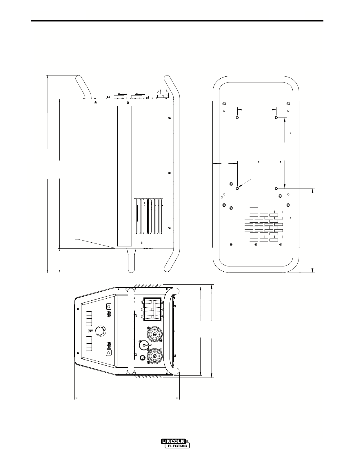
F-8
DIAGRAMS
F-8
27.82
21.60
3.44
5.50
UDE MORE THAN
10.00
N NOT PROTR
MOUNTING HOLE LOCATIONS
CHES INSIDE THE MACHINE.
0.5 IN
NOTE: MOUNTING SCREWS CA
3.50
1/4-20 NUT (4 PLACES)
8/00
M19527
4
11.8
DIMENSION PRINT
9
4.7
1
V350-PRO (CE)
0
2.44
13.1
1
Page 34

NOTES
Page 35
Now Available...12th Edition
VISA
®
Mas terC ardMasterCard
®
The Procedure Handbook of Arc Welding
With over 500,000 copies of previous editions published
since 1933, the Procedure Handbook is considered by many to
be the “Bible” of the arc welding industry.
This printing will go fast so don’t delay. Place your
order now using the coupon below.
The hardbound book contains over 750 pages of welding
information, techniques and procedures. Much of this material
has never been included in any other book.
A must for all welders, supervisors, engineers and
designers. Many welding instructors will want to use the book
as a reference for all students by taking advantage of the low
quantity discount prices which include shipping by
4th class parcel post.
$15.00 postage paid U.S.A. Mainland
How To Read Shop Drawings
The book contains the latest information and application
data on the American Welding Society Standard Welding
Symbols. Detailed discussion tells how engineers and
draftsmen use the “short-cut” language of symbols to pass
on assembly and welding information to shop personnel.
New Lessons in Arc Welding
Lessons, simply written, cover manipulatory techniques;
machine and electrode characteristics; related subjects,
such as distortion; and supplemental information on arc
welding applications, speeds and costs. Practice materials,
exercises, questions and answers are suggested for each
lesson.
528 pages, well illustrated, 6” x 9” size, bound in simulated,
gold embossed leather.
$5.00 postage paid U.S.A.
Mainland
Need Welding T raining?
The Lincoln Electric Company operates the oldest and
most respected Arc Welding School in the United States at its
corporate
dents have graduated. Tuition is low and the training is
“hands on”
For details write: Lincoln Welding School
headquarters in Cleveland, Ohio. Over 100,000 stu-
22801 St. Clair Ave.
Cleveland, Ohio 44117-1199.
Practical exercises and examples develop the reader’s
to visualize mechanically drawn objects as they will appear
in their assembled form.
187 pages with more than 100 illustrations. Size 8-1/2” x
Durable, cloth-covered board binding.
$4.50 postage paid U.S.A.
ability
11”
Mainland
and ask for bulletin ED-80 or call 216-383-2259 and ask
for the
Welding School Registrar.
Lincoln Welding School
BASIC COURSE $700.00
5 weeks of fundamentals
There is a 10% discount on all orders of $50.00 or more for shipment at one time to one location.
Orders of $50 or less before discount or orders outside of North America must be prepaid with charge, check or money order in U.S. Funds Only.
Prices include shipment by 4thClass Book Rate for U.S.A. Mainland Only. Please allow up to 4 weeks for delivery.
UPS Shipping for North America Only. All prepaid orders that request UPS shipment please add:
$5.00 For order value up to $49.99
$10.00 For order value between $50.00 & $99.99
$15.00 For order value between $100.00 & $149.00
For North America invoiced orders over $50.00 & credit card orders, if UPS is requested, it will be invoiced or charged to you at cost.
Outside U.S.A. Mainland order must be prepaid in U.S. Funds. Please add $2.00 per book for surface mail or $15.00 per book for air parcel post shipment.
METHOD OF PAYMENT: (Sorry, No C.O.D. Orders)
CHECK ONE:
Please Invoice (only if order is over $50.00)
Check or Money Order Enclosed, U.S. Funds only
Credit Card - Telephone:_______________________________________________
Account No.
USE THIS FORM TO ORDER:
BOOKS OR FREE INFORMATIVE CATALOGS Telephone: 216-383-2211 or, for fastest service, FAX this completed form to: 216-361-5901.
|_|_|_|_|_|_|_|_|_|_|_|_|_|_|_|_|_|_|_|_|_| Exp Date |_|_| |_|_|
Order from: BOOK DIVISION, The Lincoln Electric Company, 22801 St. Clair Avenue, Cleveland, Ohio 44117-1199
Name: _______________________________________________
Address: _______________________________________________
_______________________________________________
Signature as it appears on Charge Card:
Month Year
______________________
Lincoln Welding School Titles: Price Code Quantity Cost
(ED-80)
Seminar Information Procedure Handbook “Twelfth Edition” $15.00 PH
(ED-45)
Educational Video Information Incentive Management $5.00 IM
(ED-93)
James F. Lincoln Arc Welding The American Century of John C. Lincoln $5.00 AC
Foundation Book Information Welding Preheat Calculator $3.00 WC-8
(JFLF-515)
New Lessons in Arc Welding $5.00 L
How to Read Shop Drawings $4.50 H
A New Approach to Industrial Economics $5.00 NA
Pipe Welding Charts $4.50 ED-89
SUB TOTAL
Additional Shipping Costs if any
TOTAL COST
Page 36
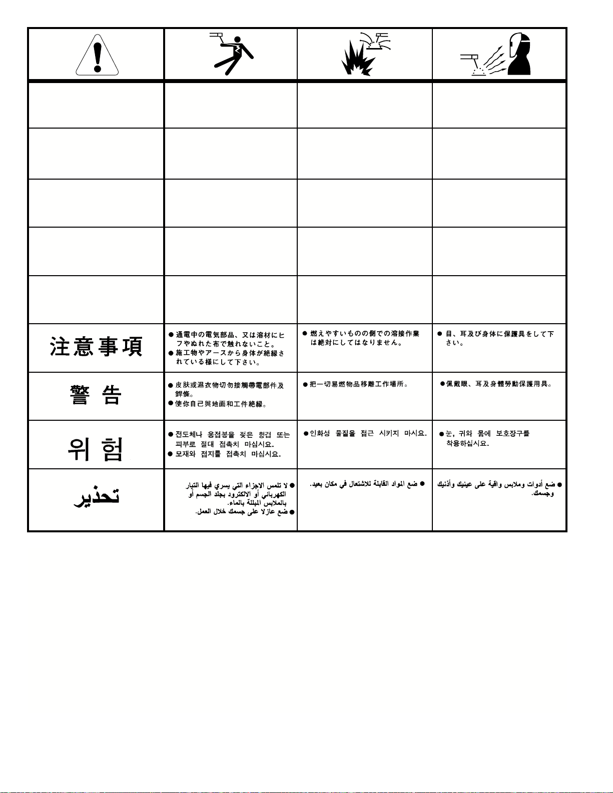
WARNING
Spanish
AVISO DE
PRECAUCION
● Do not touch electrically live parts or
electrode with skin or wet clothing.
● Insulate yourself from work and
ground.
● No toque las partes o los electrodos
bajo carga con la piel o ropa mojada.
● Aislese del trabajo y de la tierra.
● Keep flammable materials away.
● Mantenga el material combustible
fuera del área de trabajo.
● Wear eye, ear and body protection.
● Protéjase los ojos, los oídos y el
cuerpo.
French
ATTENTION
German
WARNUNG
Portuguese
ATENÇÃO
Japanese
Chinese
Korean
Arabic
● Ne laissez ni la peau ni des vête-
ments mouillés entrer en contact
avec des pièces sous tension.
● Isolez-vous du travail et de la terre.
● Berühren Sie keine stromführenden
Teile oder Elektroden mit Ihrem
Körper oder feuchter Kleidung!
● Isolieren Sie sich von den
Elektroden und dem Erdboden!
● Não toque partes elétricas e elec-
trodos com a pele ou roupa molhada.
● Isole-se da peça e terra.
● Gardez à l’écart de tout matériel
inflammable.
● Entfernen Sie brennbarres Material!
● Mantenha inflamáveis bem guarda-
dos.
● Protégez vos yeux, vos oreilles et
votre corps.
● Tragen Sie Augen-, Ohren- und Kör-
perschutz!
● Use proteção para a vista, ouvido e
corpo.
READ AND UNDERSTAND THE MANUFACTURER’S INSTRUCTION FOR THIS EQUIPMENT AND THE CONSUMABLES TO BE
USED AND FOLLOW YOUR EMPLOYER’S SAFETY PRACTICES.
SE RECOMIENDA LEER Y ENTENDER LAS INSTRUCCIONES DEL FABRICANTE PARA EL USO DE ESTE EQUIPO Y LOS
CONSUMIBLES QUE VA A UTILIZAR, SIGA LAS MEDIDAS DE SEGURIDAD DE SU SUPERVISOR.
LISEZ ET COMPRENEZ LES INSTRUCTIONS DU FABRICANT EN CE QUI REGARDE CET EQUIPMENT ET LES PRODUITS A
ETRE EMPLOYES ET SUIVEZ LES PROCEDURES DE SECURITE DE VOTRE EMPLOYEUR.
LESEN SIE UND BEFOLGEN SIE DIE BETRIEBSANLEITUNG DER ANLAGE UND DEN ELEKTRODENEINSATZ DES HERSTELLERS. DIE UNFALLVERHÜTUNGSVORSCHRIFTEN DES ARBEITGEBERS SIND EBENFALLS ZU BEACHTEN.
Page 37
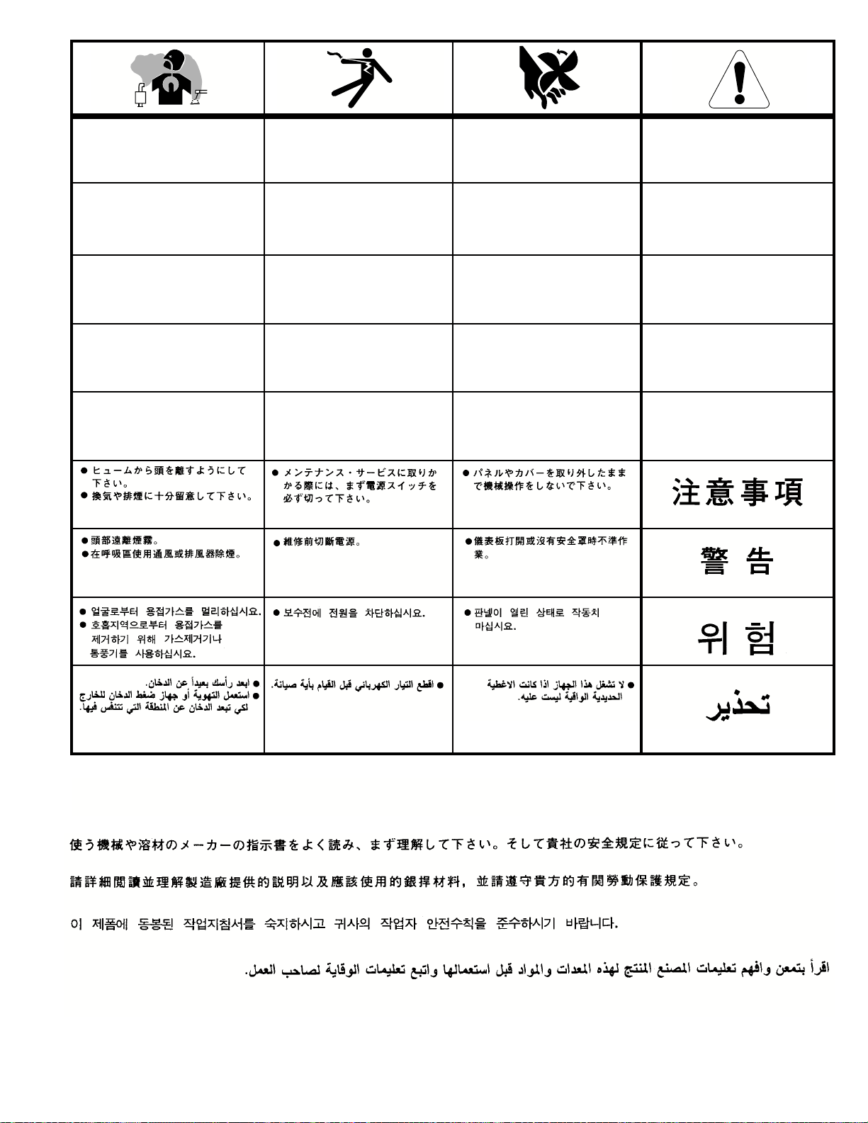
● Keep your head out of fumes.
● Use ventilation or exhaust to
remove fumes from breathing zone.
● Turn power off before servicing.
● Do not operate with panel open or
guards off.
WARNING
● Los humos fuera de la zona de res-
piración.
● Mantenga la cabeza fuera de los
humos. Utilice ventilación o
aspiración para gases.
● Gardez la tête à l’écart des fumées.
● Utilisez un ventilateur ou un aspira-
teur pour ôter les fumées des zones
de travail.
● Vermeiden Sie das Einatmen von
Schweibrauch!
● Sorgen Sie für gute Be- und
Entlüftung des Arbeitsplatzes!
● Mantenha seu rosto da fumaça.
● Use ventilação e exhaustão para
remover fumo da zona respiratória.
● Desconectar el cable de ali-
mentación de poder de la máquina
antes de iniciar cualquier servicio.
● Débranchez le courant avant l’entre-
tien.
● Strom vor Wartungsarbeiten
abschalten! (Netzstrom völlig öffnen; Maschine anhalten!)
● Não opere com as tampas removidas.
● Desligue a corrente antes de fazer
serviço.
● Não toque as partes elétricas nuas.
● No operar con panel abierto o
guardas quitadas.
● N’opérez pas avec les panneaux
ouverts ou avec les dispositifs de
protection enlevés.
● Anlage nie ohne Schutzgehäuse
oder Innenschutzverkleidung in
Betrieb setzen!
● Mantenha-se afastado das partes
moventes.
● Não opere com os paineis abertos
ou guardas removidas.
Spanish
AVISO DE
PRECAUCION
French
ATTENTION
German
WARNUNG
Portuguese
ATENÇÃO
Japanese
Chinese
Korean
Arabic
LEIA E COMPREENDA AS INSTRUÇÕES DO FABRICANTE PARA ESTE EQUIPAMENTO E AS PARTES DE USO, E SIGA AS
PRÁTICAS DE SEGURANÇA DO EMPREGADOR.
Page 38

• World's Leader in Welding and Cutting Products •
• Sales and Service through Subsidiaries and Distributors Worldwide •
Cleveland, Ohio 44117-1199 U.S.A. TEL: 216.481.8100 FAX: 216.486.1751 WEB SITE: www.lincolnelectric.com
 Loading...