

Page 1

Operator’s Manual
RETURN TO MAIN MENU
PRO-TORCH
™
WATER-COOLED
PTW-20
PTW-18
Model Numbers:
PTW-250
PTW-20, PTW-18, PTW-250,
PTW-350
PTW-350
s
:
ne
i
del
ui
NING
y G
et
f
WAR
d Sa
a
Re
s
:
e
lin
NG
de
ui
G
RNI
ty
fe
Sa
WA
ad
e
R
Register your machine:
www.lincolnelectric.com/register
Authorized Service and Distributor Locator:
www.lincolnelectric.com/locator
Save for future reference
Date Purchased
Code: (ex: 10859)
Serial: (ex: U1060512345)
IM683-A | Issue D ate Aug -13
© Lincoln Global, Inc. All Rights Reserved.
Page 2
THANK YOU FOR SELECTING
AT A LL
TIMES.
SPECIAL SITUATIONS
Addi tional precautionary measures
A QUALITY PRODUCT BY
LINCOLN ELEC TRIC.
PLEASE EXAMINE CARTON AND EQUIPMENT FOR
DAMAGE IMMEDIATELY
When this equipment is shipped, title passes to the purchaser upon
receipt by the carrier. Consequently, Claims for material damaged in
shipment must be made by the purchaser against the transportation
company at the time the shipment is received.
SAFETY DEPENDS ON YOU
Lincoln arc welding and cutting equipment is designed and built with
safety in mind. However, your overall safety can be increased by
proper installation ... and thoughtful operation on your part.
DO NOT INSTALL, OPERATE OR REPAIR THIS EQUIPMENT
WITHOUT READING THIS MANUAL AND THE SAFETY PRECAUTIONS
CONTAINED THROUGHOUT. And, most importantly, think before you
act and be careful.
WARNING
This statement appears where the information must be followed
exactly to avoid serious personal injury or loss of life.
CAUTION
This statement appears where the information must be followed to
avoid minor personal injury or damage to this equipment.
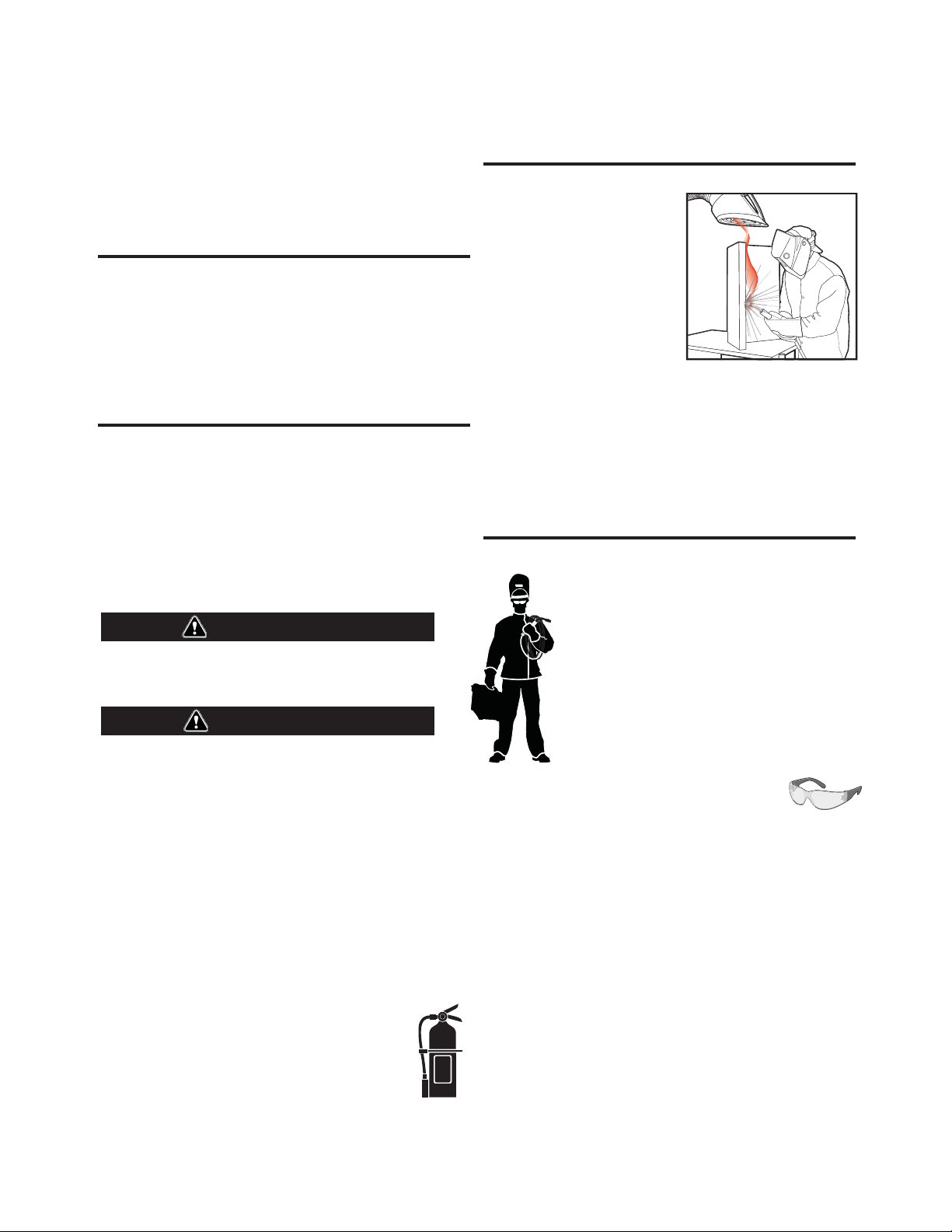
KEEP YOUR HEAD OUT OF THE FUMES.
DON’T get too close to the arc. Use
corrective lenses if necessary to
stay a reasonable distance away
from the arc.
READ and obey the Material Safety
Data Sheet (MSDS) and the warning
label that appears on all containers
of welding materials.
USE ENOUGH VENTILATION or
exhaust at the arc, or both, to keep
the fumes and gases from your breathing zone and the general area.
IN A LARGE ROOM OR OUTDOORS, natural ventilation may be
adequate if you keep your head out of the fumes (See below).
USE NATURAL DRAFTSor fans to keep the fumes away from your
face.
If you de velop unusual symptoms, see your supervisor. Perhaps the
welding atmosphere and ventilation system should be checked.
WEAR CORRECT EYE, EAR & BODY PROTECTION
PROTECT your eyes and face with welding helmet
properly fitted and with proper grade of filter plate
(See ANSI Z49.1).
PROTECT your body from welding spatter and arc
flash with protective clothing including woolen
clothing, flame-proof apron and gloves, leather
leggings, and high boots.
PROTECT others from splatter, flash, and glare with
protective screens or barriers.
IN SOME AREAS, protection from noise may be
appropriate.
BE SURE protective equipment is in good condition.
Also, wear safety glasses in work area
DO NOT WELD OR CUT containers or materials which previously had
been in contact with hazardous substances unless they are properly
cleaned. This is extremely dangerous.
DO NOT WELD OR CUT painted or plated parts unless special
precautions with ventilation have been taken. They can release highly
toxic fumes or gases.
PROTECT compressed gas cylinders from excessive heat, mechanical
shocks, and arcs; fasten cylinders so they cannot fall.
BE SURE cylinders are never grounded or part of an electrical circuit.
REMOVE all potential fire hazards from welding area.
ALWAYS HAVE FIRE FIGHTING EQUIPMENT READY FOR IMMEDIATE
USE AND KNOW HOW TO USE IT.
Page 3
SECTION A:
WARNINGS
CALIFORNIA PROPOSITION 65 WARNINGS
Diesel Engines
Diesel engine exhaust and some of its constituents are known
to the State of California to cause cancer, birth defects, and other
reproductive harm.
Gasoline Engines
The engine exhaust from this product contains chemicals known
to the State of California to cause cancer, birth defects, or other reproductive harm.
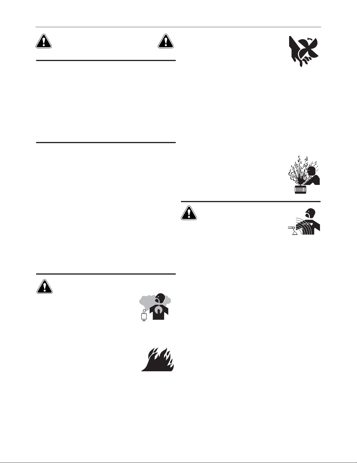
ARC WELDING CAN BE HAZARDOUS. PROTECT
YOURSELF AND OTHERS FROM POSSIBLE SERIOUS
INJURY OR DEATH. KEEP CHILDREN AWAY. PACEMAKER WEARERS SHOULD CONSULT WITH THEIR
DOCTOR BEFORE OPERATING.
Read and understand the following safety highlights. For additional
safety information, it is strongly recommended that you purchase a
copy of “Safety in Welding & Cutting - ANSI Standard Z49.1” from the
American Welding Society, P.O. Box 351040, Miami, Florida 33135 or
CSA Standard W117.2-1974. A Free copy of “Arc Welding Safety”
booklet E205 is available from the Lincoln Electric Company, 22801
St. Clair Avenue, Cleveland, Ohio 44117-1199.
BE SURE THAT ALL INSTALLATION, OPERATION,
MAINTENANCE AND REPAIR PROCEDURES ARE
PERFORMED ONLY BY QUALIFIED INDIVIDUALS.
SAFETY
1.d. Keep all equipment safety guards, covers and
devices in position and in good repair
hands, hair, cl o thing and tools away from
V-belts, gears, fans and all other moving parts
when starting, operating or repairing
equipment.
1.e. In some cases it may be necessary to remove safety guards to
perform required maintenance. Remove guards only when
necessary and replace them when the maintenance requiring
their removal is complete. Always use the greatest care when
working near moving parts.
1.f. Do not put your hands near the engine fan. Do not attempt to
override the governor or idler by pushing on the throttle control
rods while the engine is running.
1.g. To prevent accidentally starting gasoline engines while turning
the engine or welding generator during maintenance work,
disconnect the spark plug wires, distributor cap or magneto wire
as appropriate.
To avoid scalding, do not remove the radiator
1.h.
pressure cap when the engine is
.Keep
hot.
ELECTRIC AND
MAGNETIC FIELDS MAY
BE DANGEROUS
2.a. Electric current flowing through any conductor
causes localized Electric and Magnetic Fields (EMF). Welding
current creates EMF fields around welding cables and welding
machines
FOR ENGINE POWERED
EQUIPMENT.
1.a. Turn the engine off before troubleshooting
and maintenance work unless the
maintenance work requires it to be running.
1.b. Operate engines in open, well-ventilated
areas or vent the engine exhaust fumes outdoors.
1.c. Do not add the fuel near an open flame
welding arc or when the engine is running.
Stop the engine and allow it to cool before
refueling to prevent spilled fuel from
vaporizing on contact with hot engine parts
and igniting. Do not spill fuel when filling tank.
If fuel is spilled, wipe it up and do not start engine until fumes
have been eliminated.
2.b. EMF fields may interfere with some pacemakers, and welders
having a pacemaker should consult their physician before
welding.
2.c. Exposure to EMF fields in welding may have other health effects
which are now not known.
2.d. All welders should use the following procedures in order to
minimize exposure to EMF fields from the welding circuit:
2.d.1. Route the electrode and work cables together - Secure
them with tape when possible.
2.d.2. Never coil the electrode lead around your body.
2.d.3. Do not place your body between the electrode and work
cables. If the electrode cable is on your right side, the
work cable should also be on your right side.
2.d.4. Connect the work cable to the workpiece as close as
possible to the area being welded.
2.d.5.
Do not work next to welding power source.
iii
Page 4
SAFETY
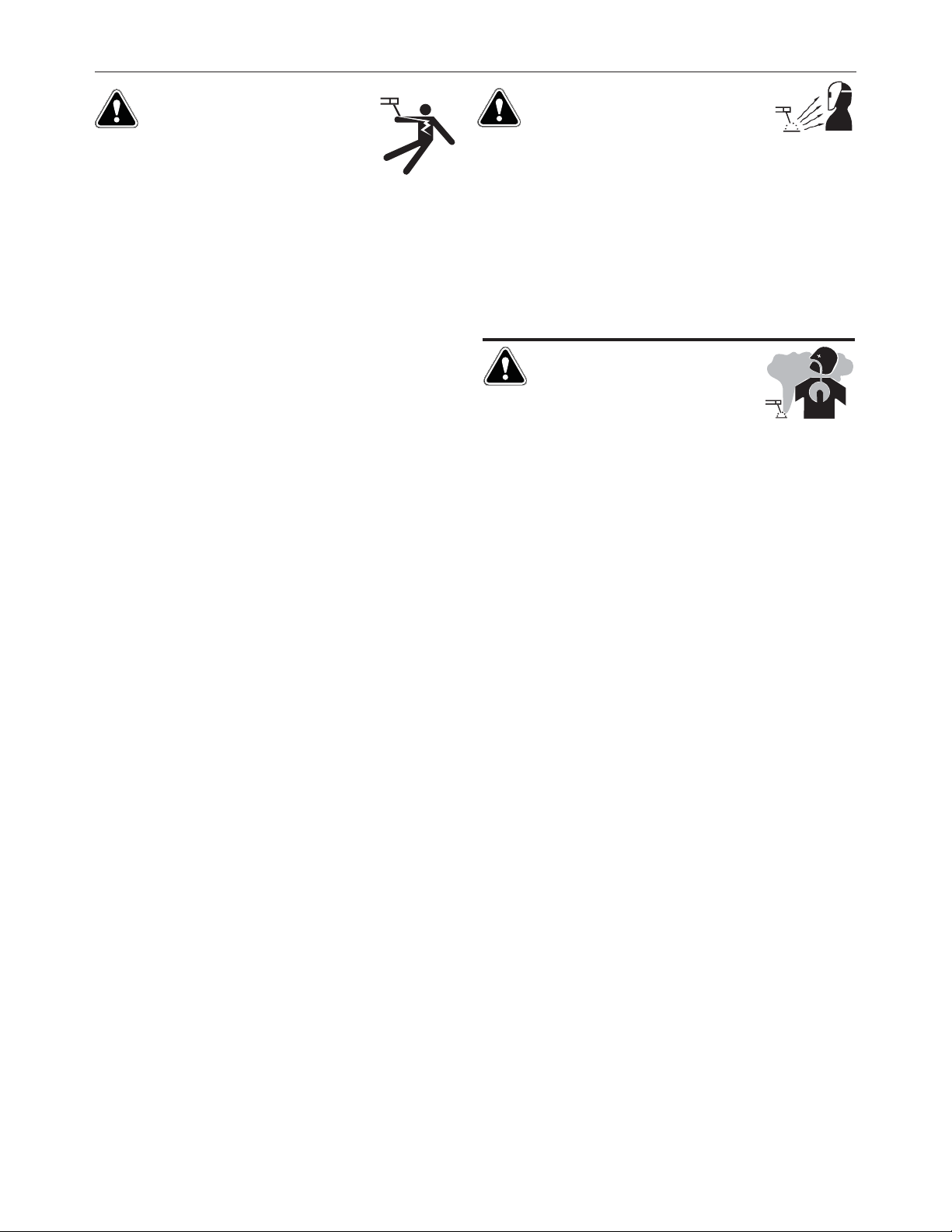
ELECTRIC SHOCK
CAN KILL.
3.a. The electrode and work (or ground) circuits are
electrically “hot” when the welder is on. Do not
touch these “hot” parts with your bare skin or
wet clothing. Wear dry, hole-free gloves to insulate hands.
3.b. Insulate yourself from work and ground using dry insulation.
Make certain the insulation is large enough to cover your full area
of physical contact with work and ground.
In addition to the normal safety precautions, if
welding must be performed under electrically
hazardous conditions (in damp locations or while
wearing wet clothing; on metal structures such as
floors, gratings or scaffolds; when in cramped
positions such as sitting, kneeling or lying, if there
is a high risk of unavoidable or accidental contact
with the workpiece or ground) use the following
equipment:
• Semiautomatic DC Constant Voltage (Wire) Welder.
• DC Manual (Stick) Welder.
• AC Welder with Reduced Voltage Control.
3.c. In semiautomatic or automatic wire welding, the electrode,
electrode reel, welding head, nozzle or semiautomatic welding
gun are also electrically “hot”.
3.d. Always be sure the work cable makes a good electrical
connection with the metal being welded. The connection should
be as close as possible to the area being welded.
3.e. Ground the work or metal to be welded to a good electrical (earth)
ground.
3.f.
Maintain the electrode holder, work clamp, welding cable and
welding machine in good, safe operating condition. Replace
damaged insulation.
3.g. Never dip the electrode in water for cooling.
3.h. Never simultaneously touch electrically “hot” parts of electrode
holders connected to two welders because voltage
two can be the total of the open circuit voltage of both
welders.
3.i. When working above floor level, use a safety belt to protect
yourself from a fall should you get a shock.
between the
ARC RAYS CAN BURN.
4.a. Use a shield with the proper filter and cover plates to protect your
eyes from sparks and the rays of the arc when welding or
observing open arc welding. Headshield and filter lens should
conform to ANSI Z87. I standards.
4.b. Use suitable clothing made from durable flame-resistant material
to protect your skin and that of your helpers from the arc rays.
4.c. Protect other nearby personnel with suitable, non-flammable
screening and/or warn them not to watch the arc nor expose
themselves to the arc rays or to hot spatter or metal.
FUMES AND GASES
CAN BE DANGEROUS.
5.a. Welding may produce fumes and gases
hazardous to health. Avoid breathing these
fumes and gases. When welding, keep your head out of the fume.
Use enough ventilation and/or exhaust at the arc to keep fumes
and gases away from the breathing zone. When welding
with electrodes which require special ventilation
such as stainless or hard facing (see instructions
on container or MSDS) or on lead or cadmium
plated steel and other metals or coatings which
produce highly toxic fumes, keep exposure as low
as possible and within applicable OSHA PEL and
ACGIH TLV limits using local exhaust or
mechanical ventilation. In confined spaces or in
some circumstances, outdoors, a respirator may
be required. Additional precautions are also
required when welding on galvanized steel.
5. b. The operation of welding fume control equipment is affected by
various factors including proper use and positioning of the
equipment, maintenance of the equipment and the specific
welding procedure and application involved. Worker exposure
level should be checked upon installation and periodically
thereafter to be certain it is within applicable OSHA PEL and
ACGIH TLV limits.
5.c. Do not weld in locations near chlorina
coming from degreasing, cleaning or spraying operations. The
heat and rays of the arc can react with solvent vapors to form
phosgene, a highly toxic gas, and other irritating products.
ted hydrocarbon vapors
3.j. Also see It ems 6.c. and 8.
5.d. Shielding gases used for arc welding can displace air and
injury or death. Always use enough ventilation, especially in
confined areas, to insure breathing air is safe.
5.e. Read and understand the manufacturer’s instructions for this
equipment and the consumables to be used, including the
material safety data sheet (MSDS) and follow your employer’s
safety practices. MSDS forms are available from your welding
distributor or from the manufacturer.
5.f. Also see item 1.b.
iv
cause
Page 5

SAFETY
WELDING AND CUTTING
SPARKS CAN CAUSE
FIRE OR EXPLOSION.
6.a. Remove fire hazards from the welding area. If
this is not possible, cover them to prevent the
welding sparks from starting a fire. Remember that welding
sparks and hot materials from welding can easily go through
small cracks and openings to adjacent areas. Avoid welding near
hydraulic lines. Have a fire extinguisher readily available.
6.b. Where compressed gases are to be used at the job site, special
precautions should be used to prevent hazardous situations. Refer
to “Safety in Welding and Cutting” (ANSI Standard Z49.1) and the
operating information for the equipment being used.
6.c. When not welding, make certain no part of the electrode circuit is
touching the work or ground. Accidental contact can cause
overheating and create a fire hazard.
6.d. Do not heat, cut or weld tanks, drums or containers until the
proper steps ha
not cause flammable or toxic vapors from substances inside. They
can cause an explosion even though they have been “cleaned”.
For information, purchase “Recommended Safe Practices for the
Preparation for Welding and Cutting of Containers and Piping That
Have Held Hazardous Substances”, AWS F4.1 from the American
Welding Society (see address above).
6.e. Vent hollow castings or containers before heating, cutting or
welding. They may explode.
6.f. Sparks and spatter are thrown from the welding arc. Wear oil free
protective garments such as leather gloves, heavy shirt, cuffless
trousers, high shoes and a cap over your hair. Wear ear plugs
when welding out of position or in confined places. Always wear
safety glasses with side shields when in a welding area.
ve been taken to insure that such procedures will
CYLINDER MAY EXPLODE IF
DAMAGED.
7.a. Use only compressed gas cylinders containing
the correct shielding gas for the process used
and properly operating regulators designed for
the gas and pressure used. All hoses, fittings,
etc. should be suitable for the application and
maintained in good condition.
7.b. Always keep cylinders in an upright position securely chained to
an undercarriage or fixed support.
7.c. Cylinders should be located:
• Away from areas where they may be struck or subjected
to physical damage.
• A safe distance from arc welding or cutting operations
and any other source of heat, sparks, or flame.
7.d. Never allow the electrode, electrode holder or any other
electrically “hot” parts to touch a cylinder.
7.e. Keep your head and face away from the cylinder valve outlet
when opening the cylinder valve.
7.f. Valve protection caps should always be in place and hand tight
except when the cylinder is in use or connected for use.
Read and follow the instructions on compressed gas cylinders,
7.g.
associated equipment, and CGA publication P-l, “Precautions for
Safe Handling of Compressed Gases in
from the Compressed Gas Association 1235 Jefferson Davis
Highway, Arlington, VA 22202.
Cylinders,” available
6.g. Connect the work cable to the work as close to the welding area
as practical.
other locations away from the welding area increase the
possibility of the welding current passing through lifting chains,
crane cables or other alternate circuits. This can create fire
hazards or overheat lifting chains or cables until they fail.
6.h. Also see item 1.c.
6.I. Read and follow NFPA 51B “ Standard for Fire Prevention During
Welding, Cutting and Other Hot Work”, available from NFPA, 1
Batterymarch Park, PO box 9101, Quincy, Ma 022690-9101.
6.j. Do not use a welding power source for pipe thawing.
Work cables connected to the building framework or
FOR ELECTRICALLY
POWERED EQUIPMENT.
8.a. Turn off input power using the disconnect
switch at the fuse box before working on the
equipment.
8.b. Install equipment in accordance with the U.S. National Electrical
Code, all local codes and the manufacturer’s recommendations.
8.c. Ground the equipment in accordance with the U.S. National
Electrical Code and the manufacturer’s recommendations.
Refer to
http://www.lincolnelectric.com/safety
for additional safety information.
Welding Safety
Interactive Web Guide
for mobile devices
v
Page 6

PTW-18 MODELS WATER-COOLED 350 AMPS
by Lincoln Electric
TORCH/REPLACEMENT PARTS
Item
1
2
3
3
4
4
5
5
6
7
8
9
10
11
12
13
14
15
Part
No.
S19261-1
S19511-2
S19512-17
S19512-20
S19512-15
S19512-18
S19512-16
S19512-19
PART OF KP504
KP2036-1B1
KP2036-2B1
S19515-7
See Chart 2
See Chart 2
See Chart 3
S19515-8
See Chart 2
See Chart 3
Industry
Reference
–––
–––
40V75R
41V30R
40V64BR
41V29BR
40V74R
41V32R
45V11
57Y02
57Y04
18CG
54N01
Description
Torch body with gaskets, PTW-18
Torch handle, PTW-18
Braided Gas hose, 12 1/2ʼ (3.8m)
Braided Gas hose, 25ʼ (7.6m)
Braided Power cable, 12 1/2ʼ (3.8m)
Braided Power cable, 25ʼ (7.6m)
Braided Water hose, 12 1/2ʼ (3.8m)
Braided Water hose, 25ʼ (7.6m)
Power cable adapter, PTW-18
Back cap, long, with “O” ring
Back cap, short, with “O” ring
Cup gasket
Collet
Collet body
Alumina nozzle
Gas lens insulator
Collet body gas lens
Alumina nozzle gas lens
3
Page 7

PTW-350 MODELS WATER-COOLED 350 AMPS
by Lincoln Electric
TORCH/REPLACEMENT PARTS
7
7
66
WARNING:
Item
1
2
3
4
5
6
7
8
9
10
11
12
13
14
15
Part
No.
S29931-10
S29931-11
S29931-8
S29931-7
S29931-9
KP2036-1B1
---
KP2036-2B1
S29931-12
See Chart 2
See Chart 2
See Chart 3
S19515-8
See Chart 2
See Chart 3
Industry
Reference
---
---
---
---
---
57Y02
34015
57Y04
---
54N01
Description
Torch Body
Torch Handle
Gas Super-flex Hose
Power Super-Flex Hose
Water In Super-Flex Hose
Back Cap, Long, With "O" Ring
Back Cap, Medium, With "O" Ring
Back Cap, Short, With "O" Ring
Heat Shield
Collet
Collet body
Alumina nozzle
Gas lens insulator
Collet body gas lens
Alumina nozzle gas lens
4
Page 8

CHART 1 – Select tungsten diameter and alumina nozzle based on current and application.
TYPICAL CURRENT RANGES FOR TUNGSTEN ELECTRODES
DCEN (-)
Balanced Wave
AC
Unbalanced Wave
(1)
Tungsten
Electrode
Diameter
in. (mm)
0.020 (0.5)
0.040 (1.0)
1/16 (1.6)
3/32 (2.4)
1/8 (3.2)
5/32 (4.0)
(1)
With argon gas.
Pure and
Alloyed
Tungsten
5- 20
15 - 80
70 - 150
150 - 250
250 - 400
400 - 500
Pure
Tungsten
10 - 20
20 - 30
30 - 80
60 -130
100 -180
160 -240
Tungsten
Alloys
5- 20
20 - 60
60 -120
100 -180
160 -250
200 -320
Pure
Tungsten
5- 15
10 - 60
50 -100
100 -160
150 -210
200 -275
Tungsten
Alloys
5- 20
15 - 80
70 -150
140 -235
225 -325
300 -400
Alumina
Nozzle
Size
4, 5, 6
4, 5, 6
5, 6
6, 7, 8
6, 7, 8
8, 10
CHART 2 – Select Collet/Collet body or Gas Lens Collet body (requires insulator) based on
tungsten diameter and application.
Tungsten
Electrode
Diameter
in. (mm)
0.020 (0.5)
0.040 (1.0)
Collet
Part No.
(Industry Ref.)
KP2030-1B1 (10N21)
KP2030-2B1 (10N22)
Collet Body
Part No.
(Industry Ref.)
KP2032-1B1 (10N29)
KP2032-2B1 (10N30)
KP2034-1B1 (45V29)
KP2034-2B1 (45V24)
Gas Lens
Collet Body
Part No.
(Industry Ref.)
1/16 (1.6)
3/32 (2.4)
1/8 (3.2)
5/32 (4.0)
CHART 3
(Alumina Gas Nozzle)
KP2030-3B1 (10N23)
KP2030-4B1 (10N24)
KP2030-5B1 (10N25)
KP2030-6B1 (54N20)
–
Select alumina gas nozzle orifice size based on application.
Standard gas nozzle, 1-27/32” (46.8mm) long, or gas lens,
1-5/8” (41.2mm) long.
Nozzle Orifice
Diameter
in. (mm)
1/4 (6)
5/16 (8)
3/8 (10)
7/16 (11)
1/2 (12.5)
5/8 (16)
11/16 (17)
(1)
Not recommended for use with high frequency current.
Size
(16th of an inch)
4
5
6
7
8
10
Short
KP2032-3B1 (10N31)
KP2032-4B1 (10N32)
KP2032-5B1 (10N28)
KP2032-6B1 (406488)
Standard Nozzle
Part No.
(Industry Ref.)
KP2016-6B1 (10N50)
KP2016-5B1 (10N49)
KP2016-4B1 (10N48)
KP2016-3B1 (10N47)
KP2016-2B1 (10N46)
KP2016-1B1 (10N45)
––
KP2034-3B1 (45V25)
KP2034-4B1 (45V26)
KP2034-5B1 (45V27)
KP2034-6B1 (45V28)
Gas Lens
Part No.
(Industry Ref.)
KP2018-5B1 (54N18)
KP2018-4B1 (54N17)
KP2018-3B1 (54N16)
KP2018-2B1 (54N15)
KP2018-1B1 (54N14)
––
KP2018-6B1
(1)
(54N19)
(1)
5
Page 9

PTW-20 MODELS WATER-COOLED 250 AMPS
by Lincoln Electric
TORCH/REPLACEMENT PARTS
Item
1
2
3
3
4
4
5
5
6
7
8
9
10
11
12
13
14
15
Part
No.
S19262-1
S19511-1
S19512-11
S19512-14
S19512-9
S19512-12
S19512-10
S19512-13
PART OF KP504
KP2035-4B1
KP2035-2B1
KP2035-1B1
S19515-6
See Chart 5
See Chart 5
See Chart 6
See Chart 5
See Chart 6
Industry
Reference
–––
–––
45V09R
45V10R
45V03R
45V04R
45V07RM
45V08RM
45V11
41V24
41V35
41V33
598882
–––
–––
–––
–––
–––
Description
Torch body with gaskets, PTW-20
Torch handle, PTW-20
Braided Gas hose, 12 1/2ʼ (3.8m)
Braided Gas hose, 25ʼ (7.6m)
Braided Power cable, 12 1/2ʼ (3.8m)
Braided Power cable, 25ʼ (7.6m)
Braided Water hose, 12 1/2ʼ (3.8m)
Braided Water hose, 25ʼ (7.6m)
Power cable adapter, PTW-20
Back cap, long, with “O” ring
Back cap, medium, with “O” ring
Back cap, short, with “O” ring
Cup gasket
Collet
Collet body
Alumina nozzle
Collet body gas lens
Alumina nozzle gas lens
6
Page 10

PTW-250 MODELS WATER-COOLED 250 AMPS
by Lincoln Electric
TORCH/REPLACEMENT PARTS
7
8
13
6
9
10
WARNING:
Item
1
2
3
4
5
6
7
8
9
10
11
12
13
14
14
11
12
KP2035-4B1
KP2035-2B1
KP2035-1B1
See Chart 5
See Chart 5
See Chart 6
See Chart 5
See Chart 6
Part
No.
S29931-4
S29931-5
S29931-2
S29931-1
S29931-3
S29931-6
Industry
Reference
---
---
---
---
---
41V24
41V35
41V33
---
---
---
---
---
---
Description
Torch Body
Torch Handle
Gas Super-flex Hose
Power Super-Flex Hose
Water In Super-Flex Hose
Back Cap, Long, With "O" Ring
Back Cap, Medium, With "O" Ring
Back Cap, Short, With "O" Ring
Heat Shield
Collet
Collet Body
Alumina Nozzle
Collet Body Gas Lens
Alumina Nozzle Gas Lens
7
Page 11

CHART 4 – Select tungsten diameter and alumina nozzle based on current and application.
TYPICAL CURRENT RANGES FOR TUNGSTEN ELECTRODES
(1)
AC
Unbalanced Wave
Pure
Tungsten
5- 15
10 - 60
50 -100
100 -160
150 -210
Tungsten
Alloys
5- 20
15 - 80
70 -150
140 -235
225 -325
Alumina
Nozzle
Size
4, 5, 6
4, 5, 6
5, 6
6, 7, 8
6, 7, 8
Tungsten
Electrode
Diameter
in. (mm)
0.020 (0.5)
0.040 (1.0)
1/16 (1.6)
3/32 (2.4)
1/8 (3.2)
(1)
With argon gas.
DCEN (-)
Pure and
Alloyed
Tungsten
5- 20
15 - 80
70 - 150
150 - 250
250 - 400
Balanced Wave
Pure
Tungsten
10 - 20
20 - 30
30 - 80
60 -130
100 -180
Tungsten
Alloys
5- 20
20 - 60
60 -120
100 -180
160 -250
CHART 5 – Select Collet/Collet body or Gas Lens Collet body (requires insulator) based on
tungsten diameter and application.
Tungsten
Electrode
Diameter
in. (mm)
Collet
Part No.
(Industry Ref.)
Collet Body
Part No.
(Industry Ref.)
Gas Lens
Collet Body
Part No.
(Industry Ref.)
0.020 (0.5)
0.040 (1.0)
1/16 (1.6)
3/32 (2.4)
1/8 (3.2)
CHART 6
Nozzle Orifice
Diameter
in. (mm)
1/4 (6)
5/16 (8)
3/8 (10)
7/16 (11)
KP2029-1B1 (13N20)
KP2029-2B1 (13N21)
KP2029-3B1 (13N22)
KP2029-4B1 (13N23)
KP2029-5B1 (13N24)
(Alumina Gas Nozzle)
(16th of an inch)
KP2031-1B1 (13N25)
KP2031-2B1 (13N26)
KP2031-3B1 (13N27)
KP2031-4B1 (13N28)
KP2031-5B1 (13N29)
–
Select alumina gas nozzle orifice size based on application.
KP2033-1B1 (45V41)
KP2033-2B1 (45V42)
KP2033-3B1 (45V43)
KP2033-4B1 (45V44)
KP2033-5B1 (45V45)
Standard gas nozzle, 1-5/32” (29.3mm) long, or gas lens,
1” (25.4mm) long.
Size
4
5
6
7
Standard Nozzle
Part No.
(Industry Ref.)
KP2017-1B1 (13N08)
KP2017-2B1 (13N09)
KP2017-3B1 (13N10)
KP2017-4B1 (13N11)
KP2019-1B1(53N58)
KP2019-2B1(53N59)
KP2019-3B1(53N60)
KP2019-4B1(53N61)
Gas Lens
Part No.
(Industry Ref.)
1/2 (12.5)
5/8 (16)
8
10
KP2017-5B1 (13N12)
KP2017-6B1 (13N13)
––
––
8
Page 12

CONNECTION DIAGRAMS
WATER-COOLED TIG TORCH – MAGNUM™ COOLER
(1)
Magnum Cooler is a unique design to be used with or without a solenoid. Diagram shows connection to power source
water solenoid to work as a demand system increasing the pump life. Magnum coolers are part of the Magnum family
of products offered by Lincoln Electric.
(1)
WATER-COOLED TIG TORCH – CITY WATER SUPPLY
Note: Refer to the manufacturerʼs power source operating manual for recommended installation practice.
9
Page 13

CONNECTION DIAGRAMS
(continued)
WATER-COOLED TIG TORCH – WATER COOLER
(1)
Water cooler does not permit use of water solenoid on power source to avoid pump damage.
Note: Refer to the manufacturerʼs power source operating manual for recommended installation practice.
(1)
HOOK-UP KIT – The hook-up kit contains the necessary hoses and accessories to connect
between your gas regulator, power source, and water supply. The KP504
hook-up kit is required for proper connection and is ordered separately.
KP504 For PTW-18 and PTW-20
Quantity
1
2
1
2
1
S19257-1 (45V11)
S19558-4 (40V76)
S19558-6 (11N18)
S19558-5 –––
S19558-1 (40V77)
Part No.
(Industry Ref.)
Description
Power cable adapter
Water hose, 12-1/2 ft. (3.8m)
Water hose coupler
Water adapter fittings, 5/8” (15.8mm)
Gas hose, 12-1/2 ft. (3.8m)
10
Page 14

WARNING
Spanish
AVISO DE
PRECAUCION
French
ATTENTION
German
WARNUNG
Portuguese
ATENÇÃO
Japanese
Chinese
Do not touch electrically live parts or
electrode with skin or wet clothing.
Insulate yourself from work and
ground.
No toque las partes o los electrodos
bajo carga con la piel o ropa mojada.
Aislese del trabajo y de la tierra.
Ne laissez ni la peau ni des vêtements
mouillés entrer en contact avec des
pièces sous tension.
Isolez-vous du travail et de la terre.
Berühren Sie keine stromführenden
Teile oder Elektroden mit Ihrem
Körper oder feuchter Kleidung!
Isolieren Sie sich von den Elektroden
und dem Erdboden!
Não toque partes elétricas e electro-
dos com a pele ou roupa molhada.
Isole-se da peça e terra.
Keep flammable materials away.
Mantenga el material combustible
fuera del área de trabajo.
Gardez à l’écart de tout matériel
inflammable.
Entfernen Sie brennbarres Material!
Mantenha inflamáveis bem guarda-
dos.
Wear eye, ear and body protection.
Protéjase los ojos, los oídos y el
cuerpo.
Protégez vos yeux, vos oreilles et
votre corps.
Tragen Sie Augen-, Ohren- und Kör-
perschutz!
Use proteção para a vista, ouvido e
corpo.
Korean
Arabic
READ AND UNDERSTAND THE MANUFACTURER’S INSTRUCTION FOR THIS EQUIPMENT AND THE
CONSUMABLES TO BE USED AND FOLLOW YOUR EMPLOYER’S SAFETY PRACTICES.
SE RECOMIENDA LEER Y ENTENDER LAS INSTRUCCIONES DEL FABRICANTE PARA EL USO DE ESTE
EQUIPO Y LOS CONSUMIBLES QUE VA A UTILIZAR, SIGA LAS MEDIDAS DE SEGURIDAD DE SU SUPERVISOR.
LISEZ ET COMPRENEZ LES INSTRUCTIONS DU FABRICANT EN CE QUI REGARDE CET EQUIPMENT ET
LES PRODUITS A ETRE EMPLOYES ET SUIVEZ LES PROCEDURES DE SECURITE DE VOTRE
EMPLOYEUR.
LESEN SIE UND BEFOLGEN SIE DIE BETRIEBSANLEITUNG DER ANLAGE UND DEN ELEKTRODENEINSATZ DES HERSTELLERS. DIE UNFALLVERHÜTUNGSVORSCHRIFTEN DES ARBEITGEBERS SIND EBENFALLS ZU BEACHTEN.
Page 15

Keep your head out of fumes.
Use ventilation or exhaust to remove
fumes from breathing zone.
Turn power off before servicing.
Do not operate with panel open or
guards off.
WARNING
Los humos fuera de la zona de res-
piración.
Mantenga la cabeza fuera de los
humos. Utilice ventilación o
aspiración para gases.
Gardez la tête à l’écart des fumées.
Utilisez un ventilateur ou un aspira-
teur pour ôter les fumées des zones
de travail.
Vermeiden Sie das Einatmen von
Schweibrauch!
Sorgen Sie für gute Be- und
Entlüftung des Arbeitsplatzes!
Mantenha seu rosto da fumaça.
Use ventilação e exhaustão para
remover fumo da zona respiratória.
Desconectar el cable de alimentación
de poder de la máquina antes de iniciar cualquier servicio.
Débranchez le courant avant l’entre-
tien.
Strom vor Wartungsarbeiten abschal-
ten! (Netzstrom völlig öffnen;
Maschine anhalten!)
Não opere com as tampas removidas.
Desligue a corrente antes de fazer
serviço.
Não toque as partes elétricas nuas.
No operar con panel abierto o
guardas quitadas.
N’opérez pas avec les panneaux
ouverts ou avec les dispositifs de
protection enlevés.
Anlage nie ohne Schutzgehäuse
oder Innenschutzverkleidung in
Betrieb setzen!
Mantenha-se afastado das partes
moventes.
Não opere com os paineis abertos
ou guardas removidas.
Spanish
AVISO DE
PRECAUCION
French
ATTENTION
German
WARNUNG
Portuguese
ATENÇÃO
Japanese
Chinese
Korean
Arabic
LEIA E COMPREENDA AS INSTRUÇÕES DO FABRICANTE PARA ESTE EQUIPAMENTO E AS PARTES DE
USO, E SIGA AS PRÁTICAS DE SEGURANÇA DO EMPREGADOR.
Page 16

CUSTOMER ASSISTANCE POLICY
The business of The Lincoln Electric Company is manufacturing and
selling high quality welding equipment, consumables, and cutting
equipment. Our challenge is to meet the needs of our customers and
to exceed their expectations. On occasion, purchasers may ask
Lincoln Electric for advice or information about their use of our
products. We respond to our customers based on the best information
in our possession at that time. Lincoln Electric is not in a position to
warrant or guarantee such advice, and assumes no liability, with
respect to such information or advice. We expressly disclaim any
warranty of any kind, including any warranty of fitness for an
customer’s particular purpose, with respect to such information or
advice. As a matter of practical consideration, we also cannot assume
any responsibility for updating or correcting any such information or
advice once it has been given, nor does the provision of information or
advice create, expand or alter any warranty with respect to the sale of
our products.
Lincoln Electric is a responsive manufacturer, but the selection and
use of specific products sold by Lincoln Electric is solely within the
control of, and remains the sole responsibility of the customer. Many
variables beyond the control of Lincoln Electric affect the results
obtained in a
requirements.
Subject to Change – This information is accurate to the best of our
knowledge at the time of printing. Please refer to
www.lincolnelectric.com for any updated information.
pplying these types of fabrication methods and service
y
 Loading...