

Page 1
RETURN TO MAIN INDEX
RETURN TO MAIN MENU
Power Wave Water Cooler
For use with machines having Code Numbers: 10730, 10844
IM680-A
November, 2002
Date of Purchase:
Serial Number:
Code Number:
Model:
Where Purchased:
Cleveland, Ohio 44117-1199 U.S.A. TEL: 216.481.8100 FAX: 216.486.1751 WEB SITE: www.lincolnelectric.com
INSTALLATION INSTRUCTIONS
Copyright © 2002 Lincoln Global Inc.
• World's Leader in Welding and Cutting Products •
• Sales and Service through Subsidiaries and Distributors Worldwide •
Page 2
i
SAFETY
i
WARNING
CALIFORNIA PROPOSITION 65 WARNINGS
Diesel engine exhaust and some of its constituents
are known to the State of California to cause cancer, birth defects, and other reproductive harm.
The Above For Diesel Engines
ARC WELDING CAN BE HAZARDOUS. PROTECT YOURSELF AND OTHERS FROM POSSIBLE SERIOUS INJURY OR DEATH.
KEEP CHILDREN AWAY. PACEMAKER WEARERS SHOULD CONSULT WITH THEIR DOCTOR BEFORE OPERATING.
Read and understand the following safety highlights. For additional safety information, it is strongly recommended that you
purchase a copy of “Safety in Welding & Cutting - ANSI Standard Z49.1” from the American Welding Society, P.O. Box
351040, Miami, Florida 33135 or CSA Standard W117.2-1974. A Free copy of “Arc Welding Safety” booklet E205 is available
from the Lincoln Electric Company, 22801 St. Clair Avenue, Cleveland, Ohio 44117-1199.
BE SURE THAT ALL INSTALLATION, OPERATION, MAINTENANCE AND REPAIR PROCEDURES ARE
PERFORMED ONLY BY QUALIFIED INDIVIDUALS.
The engine exhaust from this product contains
chemicals known to the State of California to cause
cancer, birth defects, or other reproductive harm.
The Above For Gasoline Engines
FOR ENGINE
powered equipment.
1.a. Turn the engine off before troubleshooting and maintenance
work unless the maintenance work requires it to be running.
____________________________________________________
1.b. Operate engines in open, well-ventilated
areas or vent the engine exhaust fumes
outdoors.
____________________________________________________
1.c. Do not add the fuel near an open flame
welding arc or when the engine is running.
Stop the engine and allow it to cool before
refueling to prevent spilled fuel from vaporizing on contact with hot engine parts and
igniting. Do not spill fuel when filling tank. If
fuel is spilled, wipe it up and do not start
engine until fumes have been eliminated.
____________________________________________________
1.d. Keep all equipment safety guards, covers and devices in
position and in good repair.Keep hands, hair, clothing and
tools away from V-belts, gears, fans and all other moving
parts when starting, operating or repairing equipment.
____________________________________________________
1.e. In some cases it may be necessary to remove safety
guards to perform required maintenance. Remove
guards only when necessary and replace them when the
maintenance requiring their removal is complete.
Always use the greatest care when working near moving
parts.
___________________________________________________
1.f. Do not put your hands near the engine fan.
Do not attempt to override the governor or
idler by pushing on the throttle control rods
while the engine is running.
1.h. To avoid scalding, do not remove the
radiator pressure cap when the engine is
hot.
ELECTRIC AND
MAGNETIC FIELDS
may be dangerous
2.a. Electric current flowing through any conductor causes
localized Electric and Magnetic Fields (EMF). Welding
current creates EMF fields around welding cables and
welding machines
2.b. EMF fields may interfere with some pacemakers, and
welders having a pacemaker should consult their physician
before welding.
2.c. Exposure to EMF fields in welding may have other health
effects which are now not known.
2.d. All welders should use the following procedures in order to
minimize exposure to EMF fields from the welding circuit:
2.d.1.
Route the electrode and work cables together - Secure
them with tape when possible.
2.d.2. Never coil the electrode lead around your body.
2.d.3. Do not place your body between the electrode and
work cables. If the electrode cable is on your right
side, the work cable should also be on your right side.
___________________________________________________
1.g. To prevent accidentally starting gasoline engines while
turning the engine or welding generator during maintenance
work, disconnect the spark plug wires, distributor cap or
magneto wire as appropriate.
POWER WAVE WATER COOLER
2.d.4. Connect the work cable to the workpiece as close as
possible to the area being welded.
2.d.5. Do not work next to welding power source.
Mar ‘95
Page 3
ii
SAFETY
ii
ELECTRIC SHOCK can
kill.
3.a. The electrode and work (or ground) circuits
are electrically “hot” when the welder is on.
Do not touch these “hot” parts with your bare
skin or wet clothing. Wear dry, hole-free
gloves to insulate hands.
3.b. Insulate yourself from work and ground using dry insulation.
Make certain the insulation is large enough to cover your full
area of physical contact with work and ground.
In addition to the normal safety precautions, if welding
must be performed under electrically hazardous
conditions (in damp locations or while wearing wet
clothing; on metal structures such as floors, gratings or
scaffolds; when in cramped positions such as sitting,
kneeling or lying, if there is a high risk of unavoidable or
accidental contact with the workpiece or ground) use
the following equipment:
• Semiautomatic DC Constant Voltage (Wire) Welder.
• DC Manual (Stick) Welder.
• AC Welder with Reduced Voltage Control.
3.c. In semiautomatic or automatic wire welding, the electrode,
electrode reel, welding head, nozzle or semiautomatic
welding gun are also electrically “hot”.
3.d. Always be sure the work cable makes a good electrical
connection with the metal being welded. The connection
should be as close as possible to the area being welded.
3.e. Ground the work or metal to be welded to a good electrical
(earth) ground.
ARC RAYS can burn.
4.a. Use a shield with the proper filter and cover
plates to protect your eyes from sparks and
the rays of the arc when welding or observing
open arc welding. Headshield and filter lens
should conform to ANSI Z87. I standards.
4.b. Use suitable clothing made from durable flame-resistant
material to protect your skin and that of your helpers from
the arc rays.
4.c. Protect other nearby personnel with suitable, non-flammable
screening and/or warn them not to watch the arc nor expose
themselves to the arc rays or to hot spatter or metal.
FUMES AND GASES
can be dangerous.
5.a. Welding may produce fumes and gases
hazardous to health. Avoid breathing these
fumes and gases.When welding, keep
your head out of the fume. Use enough
ventilation and/or exhaust at the arc to keep
fumes and gases away from the breathing zone. When
welding with electrodes which require special
ventilation such as stainless or hard facing (see
instructions on container or MSDS) or on lead or
cadmium plated steel and other metals or coatings
which produce highly toxic fumes, keep exposure as
low as possible and below Threshold Limit Values (TLV)
using local exhaust or mechanical ventilation. In
confined spaces or in some circumstances, outdoors, a
respirator may be required. Additional precautions are
also required when welding on galvanized steel.
3.f.
Maintain the electrode holder, work clamp, welding cable and
welding machine in good, safe operating condition. Replace
damaged insulation.
3.g. Never dip the electrode in water for cooling.
3.h. Never simultaneously touch electrically “hot” parts of
electrode holders connected to two welders because voltage
between the two can be the total of the open circuit voltage
of both welders.
3.i. When working above floor level, use a safety belt to protect
yourself from a fall should you get a shock.
3.j. Also see Items 6.c. and 8.
5.b.
Do not weld in locations near chlorinated hydrocarbon
coming from degreasing, cleaning or spraying operations.
The heat and rays of the arc can react with solvent vapors
form phosgene, a highly toxic gas, and other irritating products.
5.c. Shielding gases used for arc welding can displace air and
cause injury or death. Always use enough ventilation,
especially in confined areas, to insure breathing air is safe.
5.d. Read and understand the manufacturer’s instructions for this
equipment and the consumables to be used, including the
material safety data sheet (MSDS) and follow your
employer’s safety practices. MSDS forms are available from
your welding distributor or from the manufacturer.
5.e. Also see item 1.b.
vapors
Mar ‘95
to
POWER WAVE WATER COOLER
Page 4

iii
SAFETY
iii
WELDING SPARKS can
cause fire or explosion.
6.a.
Remove fire hazards from the welding area.
If this is not possible, cover them to prevent
the welding sparks from starting a fire.
materials from welding can easily go through small cracks
and openings to adjacent areas. Avoid welding near
hydraulic lines. Have a fire extinguisher readily available.
6.b. Where compressed gases are to be used at the job site,
special precautions should be used to prevent hazardous
situations. Refer to “Safety in Welding and Cutting” (ANSI
Standard Z49.1) and the operating information for the
equipment being used.
6.c. When not welding, make certain no part of the electrode
circuit is touching the work or ground. Accidental contact
can cause overheating and create a fire hazard.
6.d. Do not heat, cut or weld tanks, drums or containers until the
proper steps have been taken to insure that such procedures
will not cause flammable or toxic vapors from substances
inside. They can cause an explosion even
been “cleaned”. For information, purchase “Recommended
Safe Practices for the
Containers and Piping That Have Held Hazardous
Substances”, AWS F4.1 from the American Welding Society
(see address above).
6.e. Vent hollow castings or containers before heating, cutting or
welding. They may explode.
Sparks and spatter are thrown from the welding arc. Wear oil
6.f.
free protective garments such as leather gloves, heavy shirt,
cuffless trousers, high shoes and a cap over your hair. Wear
ear plugs when welding out of position or in confined places.
Always wear safety glasses with side shields when in a
welding area.
6.g. Connect the work cable to the work as close to the welding
area as practical. Work cables connected to the building
framework or other locations away from the welding area
increase the possibility of the welding current passing
through lifting chains, crane cables or other alternate circuits. This can create fire hazards or overheat lifting chains
or cables until they fail.
6.h. Also see item 1.c.
Remember that welding sparks and hot
though
they have
Preparation
for Welding and Cutting of
CYLINDER may explode
if damaged.
7.a. Use only compressed gas cylinders
containing the correct shielding gas for the
process used and properly operating
regulators designed for the gas and
pressure used. All hoses, fittings, etc. should be suitable for
the application and maintained in good condition.
7.b. Always keep cylinders in an upright position securely
chained to an undercarriage or fixed support.
7.c. Cylinders should be located:
• Away from areas where they may be struck or subjected to
physical damage.
• A safe distance from arc welding or cutting operations and
any other source of heat, sparks, or flame.
7.d. Never allow the electrode, electrode holder or any other
electrically “hot” parts to touch a cylinder.
7.e. Keep your head and face away from the cylinder valve outlet
when opening the cylinder valve.
7.f. Valve protection caps should always be in place and hand
tight except when the cylinder is in use or connected for
use.
7.g. Read and follow the instructions on compressed gas
cylinders, associated equipment, and CGA publication P-l,
“Precautions for Safe Handling of Compressed Gases in
Cylinders,” available from the Compressed Gas Association
1235 Jefferson Davis Highway, Arlington, VA 22202.
FOR ELECTRICALLY
powered equipment.
8.a. Turn off input power using the disconnect
switch at the fuse box before working on
the equipment.
8.b. Install equipment in accordance with the U.S. National
Electrical Code, all local codes and the manufacturer’s
recommendations.
8.c. Ground the equipment in accordance with the U.S. National
Electrical Code and the manufacturer’s recommendations.
Mar ‘95
POWER WAVE WATER COOLER
Page 5
iv
SAFETY
iv
PRÉCAUTIONS DE SÛRETÉ
Pour votre propre protection lire et observer toutes les instructions
et les précautions de sûreté specifiques qui parraissent dans ce
manuel aussi bien que les précautions de sûreté générales suivantes:
Sûreté Pour Soudage A L’Arc
1. Protegez-vous contre la secousse électrique:
a. Les circuits à l’électrode et à la piéce sont sous tension
quand la machine à souder est en marche. Eviter toujours
tout contact entre les parties sous tension et la peau nue
ou les vétements mouillés. Porter des gants secs et sans
trous pour isoler les mains.
b. Faire trés attention de bien s’isoler de la masse quand on
soude dans des endroits humides, ou sur un plancher
metallique ou des grilles metalliques, principalement dans
les positions assis ou couché pour lesquelles une grande
partie du corps peut être en contact avec la masse.
c. Maintenir le porte-électrode, la pince de masse, le câble
de soudage et la machine à souder en bon et sûr état
defonctionnement.
d.Ne jamais plonger le porte-électrode dans l’eau pour le
refroidir.
e. Ne jamais toucher simultanément les parties sous tension
des porte-électrodes connectés à deux machines à souder
parce que la tension entre les deux pinces peut être le
total de la tension à vide des deux machines.
f. Si on utilise la machine à souder comme une source de
courant pour soudage semi-automatique, ces precautions
pour le porte-électrode s’applicuent aussi au pistolet de
soudage.
zones où l’on pique le laitier.
6. Eloigner les matériaux inflammables ou les recouvrir afin de
prévenir tout risque d’incendie dû aux étincelles.
7. Quand on ne soude pas, poser la pince à une endroit isolé de
la masse. Un court-circuit accidental peut provoquer un
échauffement et un risque d’incendie.
8. S’assurer que la masse est connectée le plus prés possible
de la zone de travail qu’il est pratique de le faire. Si on place
la masse sur la charpente de la construction ou d’autres
endroits éloignés de la zone de travail, on augmente le risque
de voir passer le courant de soudage par les chaines de levage, câbles de grue, ou autres circuits. Cela peut provoquer
des risques d’incendie ou d’echauffement des chaines et des
câbles jusqu’à ce qu’ils se rompent.
9. Assurer une ventilation suffisante dans la zone de soudage.
Ceci est particuliérement important pour le soudage de tôles
galvanisées plombées, ou cadmiées ou tout autre métal qui
produit des fumeés toxiques.
10. Ne pas souder en présence de vapeurs de chlore provenant
d’opérations de dégraissage, nettoyage ou pistolage. La
chaleur ou les rayons de l’arc peuvent réagir avec les vapeurs
du solvant pour produire du phosgéne (gas fortement toxique)
ou autres produits irritants.
11. Pour obtenir de plus amples renseignements sur la sûreté,
voir le code “Code for safety in welding and cutting” CSA
Standard W 117.2-1974.
2. Dans le cas de travail au dessus du niveau du sol, se protéger
contre les chutes dans le cas ou on recoit un choc. Ne jamais
enrouler le câble-électrode autour de n’importe quelle partie
du corps.
3. Un coup d’arc peut être plus sévère qu’un coup de soliel,
donc:
a. Utiliser un bon masque avec un verre filtrant approprié
ainsi qu’un verre blanc afin de se protéger les yeux du rayonnement de l’arc et des projections quand on soude ou
quand on regarde l’arc.
b. Porter des vêtements convenables afin de protéger la
peau de soudeur et des aides contre le rayonnement de
l‘arc.
c. Protéger l’autre personnel travaillant à proximité au
soudage à l’aide d’écrans appropriés et non-inflammables.
4. Des gouttes de laitier en fusion sont émises de l’arc de
soudage. Se protéger avec des vêtements de protection libres
de l’huile, tels que les gants en cuir, chemise épaisse, pantalons sans revers, et chaussures montantes.
5. Toujours porter des lunettes de sécurité dans la zone de
soudage. Utiliser des lunettes avec écrans lateraux dans les
PRÉCAUTIONS DE SÛRETÉ POUR
LES MACHINES À SOUDER À
TRANSFORMATEUR ET À
REDRESSEUR
1. Relier à la terre le chassis du poste conformement au code de
l’électricité et aux recommendations du fabricant. Le dispositif
de montage ou la piece à souder doit être branché à une
bonne mise à la terre.
2. Autant que possible, I’installation et l’entretien du poste seront
effectués par un électricien qualifié.
3. Avant de faires des travaux à l’interieur de poste, la debrancher à l’interrupteur à la boite de fusibles.
4. Garder tous les couvercles et dispositifs de sûreté à leur
place.
Mar. ‘93
POWER WAVE WATER COOLER
Page 6
for selecting a QUALITY product by Lincoln Electric. We want you
Thank You
Please Examine Carton and Equipment For Damage Immediately
When this equipment is shipped, title passes to the purchaser upon receipt by the carrier. Consequently, Claims
for material damaged in shipment must be made by the purchaser against the transportation company at the
time the shipment is received.
Please record your equipment identification information below for future reference. This information can be
found on your machine nameplate.
Model Name & Number _____________________________________
Code & Serial Number _____________________________________
Date of Purchase _____________________________________
Whenever you request replacement parts for or information on this equipment always supply the information
you have recorded above.
to take pride in operating this Lincoln Electric Company product
••• as much pride as we have in bringing this product to you!
vv
Read this Operators Manual completely before attempting to use this equipment. Save this manual and keep it
handy for quick reference. Pay particular attention to the safety instructions we have provided for your protection.
The level of seriousness to be applied to each is explained below:
WARNING
This statement appears where the information must be followed exactly to avoid serious personal injury or
loss of life.
CAUTION
This statement appears where the information must be followed to avoid minor personal injury or damage to
this equipment.
EXPLANATION OF SYMBOLS THAT APPEAR ON THIS EQUIPMENT
OFF
O
ON
Page 7

vi
TABLE OF CONTENTS
Page
Installation.......................................................................................................................Section A
Technical Specifications.......................................................................................................A-1
Safety Precautions. ..............................................................................................................A-2
Installing the Water Cooler to the Power Source ..........................................................A-2
Operation.........................................................................................................................Section B
Safety Precautions. ..............................................................................................................B-1
General Description ......................................................................................................B-1
Operating Precautions ..................................................................................................B-1
Turning the System On .................................................................................................B-1
Maintenance ....................................................................................................Section D
Safety Precautions ................................................................................................D-1
Removing the Water Cooler from the Base for Service ..................................D-1
Water Cooler Periodic Maintenance .......................................................D-1,D-2
Figure 2 & Table 1 ..........................................................................................D-2
Recommended Coolants ................................................................................D-2
Filling the Reservoir ........................................................................................D-2
Water Line Connection ...................................................................................D-2
Troubleshooting..............................................................................................Section E
Safety Precautions.................................................................................................E-1
How to Use Troubleshooting Guide.......................................................................E-1
Troubleshooting Guide ..........................................................................................E-2
Wiring Diagram ......................................................................................................F-1
vi
Parts List..................................................................................................................P363
Page 8

A-1
INSTALLATION
TECHNICAL SPECIFICATIONS – Power Wave Water Cooler (K1767-1)
Model / Make Power Wave Water Cooler K1767-1
Input 230V 50/60 Hz 1 Phase
Rated Current Draw 2.8 Amps
Operating Pressure 75 psig (516 kPa) (5.2 bar)
Flow Range 0.1 to 0.8 gal/min (0.4 to 3.0 liters/min)
Use on Machines K1761, Power Wave 455/R
K1519, Power Wave 655/R
A-1
Typical MIG 0.5 gal./min (2.0 liter/min)
Operating
Flow
Open Flow 1.1 gal/min (4.3 liter/min)
Reservoir Size 1.6 gal (6.1 liter)
Coolant Requirement
Shipping Reservoir
Weight Full 135 lbs. (61.2 kg)
L 35 in. (889mm)
Dimensions W 19 in. (483mm)
H 14 in. (356mm)
See Recommended Coolants Section D-3.
POWER WAVE WATER COOLER
Page 9

A-2
INSTALLATION
SAFETY PRECAUTIONS:
WARNING
ELECTRIC SHOCK Can Kill
• Only qualified persons should perform
this installation.
HOT COOLANT CAN BURN SKIN
• Always be sure coolant is not hot
before doing any work on cooler
parts.
ROTATING FAN BLADES ARE
HAZARDOUS
• Do not put your hands near an operating fan.
• Keep all equipment safety guards, covers and
devices in position and in good repair. Keep
hands, hair, clothing and tools away from fans
and all other moving parts when starting, operating or repairing equipment.
• In some cases it may be necessary to remove
safety guards to perform required maintenance.
Remove guards only when necessary and
replace them when the maintenance requiring
their removal is complete.
est care when working near moving
------------------------------------------------------------------------
Always use the great-
parts.
A-2
4. The Power Wave 455 weights 300 pounds. Use a
suitable overhead crane or equivalent lifting device
to safely raise the Power Wave 455 by its lift bale.
Place temporary supports (4 x 4 in Lumber) across
the cooler at points shown to support the power
source. Lower the Power Wave 455 onto temporary
supports. Do not remove overhead crane.
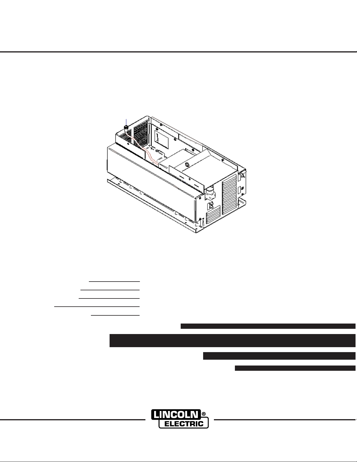
5. Connect the circular connector at the rear of the
water cooler to the connector at the rear of the
power source.
6. Remove temporary supports and carefully finish
lowering the power source onto the water cooler
and line up the mounting holes in the channels at
the base of the power source.
7. Using the four 3/8 screws provided, fasten the water
cooler to the power source.
8. Connect the two front leads from step 3 to the terminal strip at the front of the power source.
ATTACHING THE WATER COOLER TO
THE POWER SOURCE:
1. Preparation:
WARNING
• Always turn off the power to the water cooler
and to the power source before servicing the
machine.
• Always disconnect the Power Wave machine
from its service input power before servicing the
machine.
2. Detach all shipping material from the water cooler.
3. Make sure the wiring bundle with two leads in it is
routed toward the front of the water cooler through
the 1” diameter opening in the sheet metal (see
Figure 1).
CIRCULAR
CONNECTOR
(STEP 5)
TEMPORARY
SUPPORT
POINTS
WATER COOLER
SCREWS (4)
(STEP 7)
FIGURE 1
POWER WAVE 455
1.00” HOLE FOR
WIRING BUNDLE
(STEP 3)
POWER WAVE WATER COOLER
Page 10

B-1
SAFETY PRECAUTIONS
OPERATION
OPERATING PRECAUTIONS
B-1
WARNING
ELECTRIC SHOCK can kill.
• Disconnect input power by removing plug from receptacle before
working inside Cooler.
• Do not operate with covers
removed.
• Use only grounded receptacle.
• Do not remove the power cord ground prong.
• Do not touch electrically “hot” parts inside
Cooler.
• Have qualified personnel do the installation,
maintenance and troubleshooting work.
---------------------------------------------------------------------
See additional warning information at
front of this operator’s manual.
-----------------------------------------------------------
GENERAL DESCRIPTION:
The Power Wave Cooler is specifically designed to
work with select Power Wave’s type power sources
for MIG and TIG guns and torches. It mounts directly
underneath the power source to conserve floor space.
Integral to the cooler is a flow switch to protect welding guns when water flow is interrupted. Electrical
power for the cooler is supplied by the power source.
The following should always be observed when
operating any Power Wave Water Cooler:
WARNING
• Never operate the G3503-[ ] cooler outside of its
case, or without access door in place.
• Immersion in water around electrical lines can
cause electrical shock.
• Never place fingers into openings of Cooler.
Moving parts can injure.
• Turn off power to the Power Wave or the disconnect switch before filling the reservoir.
• Never operate the Cooler with the reservoir fill cap
off. (See Figure 1.A)
RESERVOIR FILL CAP
WATER IN
WATER OUT
YELLOW LED “FLOW
FAULT”
The following should always be observed when operating any Power Wave Water Cooler:
• Check the reservoir daily. (See Figure 3)
• Keep the reservoir full especially after changing any
water lines.
• The power to the Cooler should be turned off when
welding is not taking place for a long period of time.
• Be certain that the Cooler is on (power switch in the
“I” position) before beginning to weld.
• Never operate the Cooler with the reservoir fill cap
removed.
• Avoid placing the Cooler near areas of extreme
heat.
• Avoid placing the Cooler near a flux hopper or an
area where dust build-up is extreme.
• Avoid kinking or putting sharp bends in any water
lines.
• Keep all water lines clean.
TURNING THE SYSTEM ON
After filling the reservoir and connecting the coolant
hoses to the Power Wave Water Cooler per the
Installation Section, turn the Water Cooler on.
You will be able to hear the unit running and feel air
flow out of the front of the K1767-1 when the Cooler is
operating. The Cooler will run continuously when the
Power Wave is turned on.
When first starting the unit, check all of the water lines
to insure that no coolant leaks are present. Leakage
causes poor welding performance, poor cooling performance, low welding component life and potential
electrical safety hazards.
Turn the primer switch on and hold for ten seconds.
coolant will start to flow through the system and the
green LED “Flow on” will light, when the primer switch
is released the pump will remain on and continue to
circulate coolant.
If the flow sensor detects low flow, the pump will stop
operating and the YELLOW LED “Flow Fault” will light.
A signal will be sent to the Power Wave to stop welding to protect the welding gun or torch. (See Figure
1.a)
Refer to the troubleshooting guide to find the potential
causes of the coolant flow fault.
ON/OFF SWITCH
CIRCUIT BREAKER
GREEN LED “FLOW ON”
PRIME SWITCH
Figure 1.A
POWER WAVE WATER COOLER
Page 11

D-1
MAINTENANCE
D-1
SAFETY PRECAUTIONS
WARNING
ELECTRIC SHOCK can kill.
• Disconnect input power by removing plug from receptacle before
working inside Cooler.
• Do not operate with covers
removed.
• Use only grounded receptacle.
• Do not remove the power cord ground prong.
• Do not touch electrically “hot” parts inside
Cooler.
• Have qualified personnel do the installation,
maintenance and troubleshooting work.
---------------------------------------------------------------------
See additional warning information at
front of this operator’s manual.
-----------------------------------------------------------
REMOVING THE G3503-[ ] WATER COOLER FROM THE BASE FOR SERVICE:
WARNING
• Always turn off the power to the water cooler
and to the power source before servicing the
machine.
• Always disconnect the Power Wave machine
from its service input power before servicing
the machine.
• Do not remove the pump relief valves 3/4” hex
nut or attempt to adjust the relief valve setting.
1. Remove the front panel by removing the four
screws holding it in place. Save the screws.
2. Remove both fasteners from the base which hold
the cooler in place. Carefully pull the water cooler
forward until the cooler’s Molex connectors are visible.
3. Disconnect both the water cooler’s Molex connectors.
4. Pull the water cooler completely out of the machine.
5. Perform service or periodic maintenance on the
cooler.
6. Reinstall the water cooler by reversing steps 1 through 4.
7. If necessary, fill the water cooler with recommended coolant (Page D-3) to level shown (Figure
2,Page D-2).
8. Prime the cooler:
a. Keep accessories’ hose lengths horizontal,
either coiled or straight, and no higher than 4
feet of the specified coolant level (Fig. 2).
b. Switch on the Power Wave machine.
c. Turn on and hold the PRIME switch for approxi-
mately 10 seconds until the green LED “flow
on” lights.
9. Check coolant level. Add more if required.
WATER COOLER PERIODIC MAINTENANCE
1. Preparation:
WARNING
• Always switch off the Power Wave machine
power.
• Always disconnect the Power Wave
machine from service input power.
• Do not remove the pump relief valves 3/4
in. acorn hex nut or attempt to adjust the
relief valve setting.
2. Remove the cooler G3503-[ ] from the Power
Wave machine.
3. Clean the pumps inlet strainer:
• Drain the reservoir of coolant and dispose of it
in an environmentally responsible manner (see
Recommended Coolants).
• Place absorbent towels underneath pump
head.
• Hold pump head to apply counter torque when
loosening strainers 7/8 acorn nut. Do not confuse with 3/4 acorn nut. Remove nut and slide
inlet strainer down and out from pump head.
• Gently rinse strainer under running water to
thoroughly clean it.
• Use the mirror to inspect inside of pump for
contamination. Carefully remove hardened
debris with dental pick if necessary, without
scratching inside of the pump.
• Reinstall strainer and acorn nut, tightening
with 75±15 in.-lbs. of torque. Wipe dry all
areas wetted by coolant. Dispose of towels in
an environmentally responsible manner (see
Recommended Coolants).
4. Remove fan shroud and inspect hoses and electrical harnesses for kinking or damage (cut, abrasion,
swelling, etc.). Replace if necessary.
5. Remove accumulated dust from cooler, especially
from the motor and heat exchanger, by blowing it
off with shop air or vacuuming it out.
• The heat exchanger fins are sharp but can be
easily bent. Treat them with care to avoid personal injury and damaging them.
• Remove the cooler from the machine for a
more thorough cleaning job.
6. Motor lubrication is recommended once a year:
• Remove plug over lube port at top of motor
near fan end.
• Add 20 drops of electric motor or SAE 10 oil
then reinstall plug.
POWER WAVE WATER COOLER
Page 12

Front
of
Power Wave Machine
D-2
MAINTENANCE
7. Flush coolant from the system and replace with
fresh, recommended coolant at least once a year.
More frequent flushing may be necessary, depending upon a user’s particular system or its usage.
NOTE: Never run the pump dry. Always use a recom-
mended coolant, otherwise pump damage
may result.
D-2
9. Prime the cooler:
a. Keep accessories’ hose lengths horizontal,
either coiled or straight, and no higher than 4
feet of the specified coolant level (Fig. 2).
b. Switch on the Power Wave machine.
c. Turn on and hold the PRIME switch for approxi-
mately 10 seconds until the green LED “flow
on” lights .
8. Reinstall the cooler into the Power Wave machine.
Reservoir Screen
Visible Coolant Level
0.25 to 0.50
inches
10. Check coolant level. Add more if required.
Figure 2. Specified coolant level.
Figure 2. Specified coolant level.
TABLE 1
COOLER ELECTRICAL HARNESS PIN-OUTS
Molex Molex Description
Connector Pin No.
large 1 Ground
large 2 Motor Common
large 3 Unused
large 4 Unused
large 5 Motor 230 VAC Functions on (PW 450 ONLY)
large 6 Motor 230 VAC Functions on (PW 455 / PW 655)
small 1 Unused
small 2 Unused
small 3 Relay coil
small 4 Relay coil
small 5 Pressure Switch - NO contact
small 6 Pressure Switch - common contact
POWER WAVE WATER COOLER
Page 13

D-3
MAINTENANCE
RECOMMENDED COOLANTS
1. The following coolants have been determined to be
compatible with the wetted materials used in the
cooler assembly:
• Distilled or deionized water
• Potable tap water
• Sediment-free mixtures containing a maxi-
mum of 50% ethylene glycol or automotivegrade antifreeze and the balance of distilled
or deionized water.
2. Ethylene glycol mixtures should be selected if the
cooler may be exposed to a temperature below the
freezing point of water.
3. Consult gun, torch, and wire feeder manuals for
coolant recommendations and select one from the
above list.
4. Pure solutions and mixtures of, or materials (i.e.
towels) wetted with ethylene glycol are toxic to
humans and animals. They must not be haphazardly discarded, especially by pouring liquids down
the drain. Contact the local EPA office for responsible disposal methods or for recycling information.
D-3
5. The cooler’s reservoir has a nominal liquid capacity
of 1.6 gallons.(6.1 Liters)
FILLING THE RESERVOIR
The cooler is shipped from the factory with a 50 / 50
mixture of ethylene glycol and water as coolant.
• Be certain to replace the reservoir fill cap when the
reservoir is full. Operation of the Power Wave
Water Cooler without the fill cap in place can cause
evaporation loss of coolant or low product life.
WATER LINE CONNECTION
Each Water Cooler model contains two female quick
disconnect fittings to mate with water hoses typically
used in the welding market.
Take the accessory INLET hose (colored or tagged
blue on most hoses) and insert it into the cooler’s
“Coolant Out” fitting. Then take the accessory OUTLET hose (colored or tagged red on most hoses) and
insert it into the cooler’s “Coolant In” fitting. Make sure
the connectors are fully inserted. BE CERTAIN THAT
NO LEAKS EXIST WHEN COOLER IS TURNED ON.
A LEAK WILL DEPLETE RESERVOIR VOLUME,
CAUSE POOR COOLING PERFORMANCE AND
REDUCE GUN OR TORCH LIFE.
POWER WAVE WATER COOLER
Page 14

E-1
TROUBLESHOOTING
HOW TO USE TROUBLESHOOTING GUIDE
WARNING
Service and Repair should only be performed by Lincoln Electric Factory Trained Personnel.
Unauthorized repairs performed on this equipment may result in danger to the technician and
machine operator and will invalidate your factory warranty. For your safety and to avoid Electrical
Shock, please observe all safety notes and precautions detailed throughout this manual.
__________________________________________________________________________
E-1
This Troubleshooting Guide is provided to help you
locate and repair possible machine malfunctions.
Simply follow the three-step procedure listed below.
Step 1. LOCATE PROBLEM (SYMPTOM).
Look under the column labeled “PROBLEM (SYMPTOMS)”. This column describes possible symptoms
that the machine may exhibit. Find the listing that
best describes the symptom that the machine is
exhibiting.
Step 2. POSSIBLE CAUSE.
The second column labeled “POSSIBLE CAUSE” lists
the obvious external possibilities that may contribute
to the machine symptom.
Step 3. RECOMMENDED COURSE OF ACTION
This column provides a course of action for the
Possible Cause, generally it states to contact your
local Lincoln Authorized Field Service Facility.
If you do not understand or are unable to perform the
Recommended Course of Action safely, contact your
local Lincoln Authorized Field Service Facility.
CAUTION
If for any reason you do not understand the test procedures or are unable to perform the tests/repairs safely, contact your
Local Lincoln Authorized Field Service Facility for technical troubleshooting assistance before you proceed.
POWER WAVE WATER COOLER
Page 15

E-2
PROBLEMS
(SYMPTOMS)
TROUBLESHOOTING
Observe all Safety Guidelines detailed throughout this manual
POSSIBLE AREAS OF
MISADJUSTMENTS(S)
RECOMMENDED
COURSE OF ACTION
E-2
Cooler does not operate with power
switch on.
(Switch pushed to
"1" position.) No “ LED” Turn on.
Cooler does not operate with power
switch on, YELLOW LED “Flow
Fault” is on.
Internal water leak.
Torch or gun runs hot.
1. Power cord unplugged to powerwave not plugged in.
2. Power switch faulty.
3. Power harness damaged.
1. Water lines blocked or crimped.
2. Leak in gun or water hoses.
3. Reservoir empty.
4. Female quick-connect fittings are
not connected to male fittings.
5. The system needs to be primed.
1. Hose clamp loose on internal
hose.
2. Internal hose punctured.
3. Heat exchanger leaking.
1. Unit placed by area of extreme
heat.
2. Low coolant flow.
3. No coolant flow.
4. Fan not operating.
5. Heat exchanger clogged.(Air or
coolant side)
6. Torch or Gun exceeds cooler rat-
ing.
7. Welding output not disabled with
low or no coolant flow.
If all recommended possible areas
of misadjustment have been
checked and the problem persists,
Contact your local Lincoln
Authorized Field Service Facility.
Fan operates but there is low
coolant flow. (Cooler will not continuously operate)
Fan operates but there is no coolant
flow. (Cooler will not continuously
operate)
Cooler trips outlet circuit breaker.
The Cooler is on, but the Power
Wave still indicates that there is a
water fault.
1. Leak in torch/gun or hoses.
2. Torch/gun or hoses partially
obstructed.
3. Pressure low (pump failing).
1. Pump motor failure.
2. Reservoir empty.
1. Circuit overloaded.
1. Verify that there is actually coolant
flow (ie no blocked connections,
proper coolant level)
2. Check that all connections in the
Power Wave’s green I/O connector are tight and that any insulation is not pinched
CAUTION
If for any reason you do not understand the test procedures or are unable to perform the tests/repairs safely, contact your
Local Lincoln Authorized Field Service Facility for technical troubleshooting assistance before you proceed.
POWER WAVE WATER COOLER
Page 16

F-1
DIAGRAMS
F-1
3.0A
SW1 (RUN)
B
M19822
SOURCE
862
AC
-
PIN 11
PIN 9
868
866A
SW3
(PRIME)
869B
TO POWER
863
862
864
859B
1
2
3
4
567
8
9
11
10
12
8
16
9
1
3
1
2
J32
J31
7
5
4
9
6
8
10
11
1213141516
12
16
7
PERIPHERAL BOARD
869
865
3
866
868
867
861B
AC
6
(P3)
1
4
867A
869A
861A
859A
6
5
312
4
870
LED (G)
LED (Y)
863
D1
AC +
861
AC +
859
8
11
12
1CR
BASE
COOLER
FLOW
SWITCH
T1
5
6
2
M
MOTOR
CHASSIS
350B
2.5A
1
350A
CB1
350
3
4
2
K1767-1 WATER COOLER WIRING DIAGRAM
3
1
6
6
(P4)
5
2
3
4
1
4
352A
350B
GND
352B
352A
350
352
GND
2
3
4
FROM POWER
SOURCE
1
7
10 VAC
2.50 A
1
220VAC
COMPONENT
ELECTRICAL SYMBOLS PER E1537
MTG. PLATE
POWER WAVE WATER COOLER
Page 17

NOTES
POWER WAVE WATER COOLER
Page 18

WARNING
Spanish
AVISO DE
PRECAUCION
● Do not touch electrically live parts or
electrode with skin or wet clothing.
● Insulate yourself from work and
ground.
● No toque las partes o los electrodos
bajo carga con la piel o ropa mojada.
● Aislese del trabajo y de la tierra.
● Keep flammable materials away.
● Mantenga el material combustible
fuera del área de trabajo.
● Wear eye, ear and body protection.
● Protéjase los ojos, los oídos y el
cuerpo.
French
ATTENTION
German
WARNUNG
Portuguese
ATENÇÃO
Japanese
Chinese
Korean
Arabic
● Ne laissez ni la peau ni des vête-
ments mouillés entrer en contact
avec des pièces sous tension.
● Isolez-vous du travail et de la terre.
● Berühren Sie keine stromführenden
Teile oder Elektroden mit Ihrem
Körper oder feuchter Kleidung!
● Isolieren Sie sich von den
Elektroden und dem Erdboden!
● Não toque partes elétricas e elec-
trodos com a pele ou roupa molhada.
● Isole-se da peça e terra.
● Gardez à l’écart de tout matériel
inflammable.
● Entfernen Sie brennbarres Material!
● Mantenha inflamáveis bem guarda-
dos.
● Protégez vos yeux, vos oreilles et
votre corps.
● Tragen Sie Augen-, Ohren- und Kör-
perschutz!
● Use proteção para a vista, ouvido e
corpo.
READ AND UNDERSTAND THE MANUFACTURER’S INSTRUCTION FOR THIS EQUIPMENT AND THE CONSUMABLES TO BE
USED AND FOLLOW YOUR EMPLOYER’S SAFETY PRACTICES.
SE RECOMIENDA LEER Y ENTENDER LAS INSTRUCCIONES DEL FABRICANTE PARA EL USO DE ESTE EQUIPO Y LOS
CONSUMIBLES QUE VA A UTILIZAR, SIGA LAS MEDIDAS DE SEGURIDAD DE SU SUPERVISOR.
LISEZ ET COMPRENEZ LES INSTRUCTIONS DU FABRICANT EN CE QUI REGARDE CET EQUIPMENT ET LES PRODUITS A
ETRE EMPLOYES ET SUIVEZ LES PROCEDURES DE SECURITE DE VOTRE EMPLOYEUR.
LESEN SIE UND BEFOLGEN SIE DIE BETRIEBSANLEITUNG DER ANLAGE UND DEN ELEKTRODENEINSATZ DES HERSTELLERS. DIE UNFALLVERHÜTUNGSVORSCHRIFTEN DES ARBEITGEBERS SIND EBENFALLS ZU BEACHTEN.
Page 19

● Keep your head out of fumes.
● Use ventilation or exhaust to
remove fumes from breathing zone.
● Turn power off before servicing.
● Do not operate with panel open or
guards off.
WARNING
● Los humos fuera de la zona de res-
piración.
● Mantenga la cabeza fuera de los
humos. Utilice ventilación o
aspiración para gases.
● Gardez la tête à l’écart des fumées.
● Utilisez un ventilateur ou un aspira-
teur pour ôter les fumées des zones
de travail.
● Vermeiden Sie das Einatmen von
Schweibrauch!
● Sorgen Sie für gute Be- und
Entlüftung des Arbeitsplatzes!
● Mantenha seu rosto da fumaça.
● Use ventilação e exhaustão para
remover fumo da zona respiratória.
● Desconectar el cable de ali-
mentación de poder de la máquina
antes de iniciar cualquier servicio.
● Débranchez le courant avant l’entre-
tien.
● Strom vor Wartungsarbeiten
abschalten! (Netzstrom völlig öffnen; Maschine anhalten!)
● Não opere com as tampas removidas.
● Desligue a corrente antes de fazer
serviço.
● Não toque as partes elétricas nuas.
● No operar con panel abierto o
guardas quitadas.
● N’opérez pas avec les panneaux
ouverts ou avec les dispositifs de
protection enlevés.
● Anlage nie ohne Schutzgehäuse
oder Innenschutzverkleidung in
Betrieb setzen!
● Mantenha-se afastado das partes
moventes.
● Não opere com os paineis abertos
ou guardas removidas.
Spanish
AVISO DE
PRECAUCION
French
ATTENTION
German
WARNUNG
Portuguese
ATENÇÃO
Japanese
Chinese
Korean
Arabic
LEIA E COMPREENDA AS INSTRUÇÕES DO FABRICANTE PARA ESTE EQUIPAMENTO E AS PARTES DE USO, E SIGA AS
PRÁTICAS DE SEGURANÇA DO EMPREGADOR.
Page 20

• World's Leader in Welding and Cutting Products •
• Sales and Service through Subsidiaries and Distributors Worldwide •
Cleveland, Ohio 44117-1199 U.S.A. TEL: 216.481.8100 FAX: 216.486.1751 WEB SITE: www.lincolnelectric.com
 Loading...