

Page 1

IM657
RETURN TO MAIN MENU
RED-D-ARC
DC-600
For use with machines having Code Numbers:
December, 2000
10650
OPERATOR’S MANUAL
Red-D-Arc Spec-Built Welding Equipment
This RED-D-ARC welder is built to RED-D-ARC Extreme Duty
design specifications by Lincoln Electric.
Safety Depends on You
This welder is designed and built with safety in mind.
However, your overall safety can be increased by proper installation
... and thoughtful operation on your part.
DO NOT INSTALL, OPERATE OR REPAIR THIS EQUIPMENT
WITHOUT READING THIS MANUAL AND THE SAFETY
PRECAUTIONS CONTAINED THROUGHOUT.
And, most importantly, think before you act and be careful.
1-800-245-3660
North America’s Largest Fleet of Welding Equipment
Page 2
i
SAFETY
i
WARNING
CALIFORNIA PROPOSITION 65 WARNINGS
Diesel engine exhaust and some of its constituents
are known to the State of California to cause cancer, birth defects, and other reproductive harm.
The Above For Diesel Engines
ARC WELDING CAN BE HAZARDOUS. PROTECT YOURSELF AND OTHERS FROM POSSIBLE SERIOUS INJURY OR DEATH.
KEEP CHILDREN AWAY. PACEMAKER WEARERS SHOULD CONSULT WITH THEIR DOCTOR BEFORE OPERATING.
Read and understand the following safety highlights. For additional safety information, it is strongly recommended that you
purchase a copy of “Safety in Welding & Cutting - ANSI Standard Z49.1” from the American Welding Society, P.O. Box
351040, Miami, Florida 33135 or CSA Standard W117.2-1974. A Free copy of “Arc Welding Safety” booklet E205 is available
from the Lincoln Electric Company, 22801 St. Clair Avenue, Cleveland, Ohio 44117-1199.
BE SURE THAT ALL INSTALLATION, OPERATION, MAINTENANCE AND REPAIR PROCEDURES ARE
PERFORMED ONLY BY QUALIFIED INDIVIDUALS.
The engine exhaust from this product contains
chemicals known to the State of California to cause
cancer, birth defects, or other reproductive harm.
The Above For Gasoline Engines
FOR ENGINE
powered equipment.
1.a. Turn the engine off before troubleshooting and maintenance
work unless the maintenance work requires it to be running.
____________________________________________________
1.b. Operate engines in open, well-ventilated
areas or vent the engine exhaust fumes
outdoors.
____________________________________________________
1.c. Do not add the fuel near an open flame
welding arc or when the engine is running.
Stop the engine and allow it to cool before
refueling to prevent spilled fuel from vaporizing on contact with hot engine parts and
igniting. Do not spill fuel when filling tank. If
fuel is spilled, wipe it up and do not start
engine until fumes have been eliminated.
____________________________________________________
1.d. Keep all equipment safety guards, covers and devices in
position and in good repair.Keep hands, hair, clothing and
tools away from V-belts, gears, fans and all other moving
parts when starting, operating or repairing equipment.
____________________________________________________
1.e. In some cases it may be necessary to remove safety
guards to perform required maintenance. Remove
guards only when necessary and replace them when the
maintenance requiring their removal is complete.
Always use the greatest care when working near moving
parts.
___________________________________________________
1.f. Do not put your hands near the engine fan.
Do not attempt to override the governor or
idler by pushing on the throttle control rods
while the engine is running.
1.h. To avoid scalding, do not remove the
radiator pressure cap when the engine is
hot.
ELECTRIC AND
MAGNETIC FIELDS
may be dangerous
2.a. Electric current flowing through any conductor causes
localized Electric and Magnetic Fields (EMF). Welding
current creates EMF fields around welding cables and
welding machines
2.b. EMF fields may interfere with some pacemakers, and
welders having a pacemaker should consult their physician
before welding.
2.c. Exposure to EMF fields in welding may have other health
effects which are now not known.
2.d. All welders should use the following procedures in order to
minimize exposure to EMF fields from the welding circuit:
2.d.1.
Route the electrode and work cables together - Secure
them with tape when possible.
2.d.2. Never coil the electrode lead around your body.
2.d.3. Do not place your body between the electrode and
work cables. If the electrode cable is on your right
side, the work cable should also be on your right side.
___________________________________________________
1.g. To prevent accidentally starting gasoline engines while
turning the engine or welding generator during maintenance
work, disconnect the spark plug wires, distributor cap or
magneto wire as appropriate.
2.d.4. Connect the work cable to the workpiece as close as
possible to the area being welded.
2.d.5. Do not work next to welding power source.
Mar ‘95
DC-600
Page 3
ii
SAFETY
ii
ELECTRIC SHOCK can
kill.
3.a. The electrode and work (or ground) circuits
are electrically “hot” when the welder is on.
Do not touch these “hot” parts with your bare
skin or wet clothing. Wear dry, hole-free
gloves to insulate hands.
3.b. Insulate yourself from work and ground using dry insulation.
Make certain the insulation is large enough to cover your full
area of physical contact with work and ground.
In addition to the normal safety precautions, if welding
must be performed under electrically hazardous
conditions (in damp locations or while wearing wet
clothing; on metal structures such as floors, gratings or
scaffolds; when in cramped positions such as sitting,
kneeling or lying, if there is a high risk of unavoidable or
accidental contact with the workpiece or ground) use
the following equipment:
• Semiautomatic DC Constant Voltage (Wire) Welder.
• DC Manual (Stick) Welder.
• AC Welder with Reduced Voltage Control.
3.c. In semiautomatic or automatic wire welding, the electrode,
electrode reel, welding head, nozzle or semiautomatic
welding gun are also electrically “hot”.
3.d. Always be sure the work cable makes a good electrical
connection with the metal being welded. The connection
should be as close as possible to the area being welded.
3.e. Ground the work or metal to be welded to a good electrical
(earth) ground.
ARC RAYS can burn.
4.a. Use a shield with the proper filter and cover
plates to protect your eyes from sparks and
the rays of the arc when welding or observing
open arc welding. Headshield and filter lens
should conform to ANSI Z87. I standards.
4.b. Use suitable clothing made from durable flame-resistant
material to protect your skin and that of your helpers from
the arc rays.
4.c. Protect other nearby personnel with suitable, non-flammable
screening and/or warn them not to watch the arc nor expose
themselves to the arc rays or to hot spatter or metal.
FUMES AND GASES
can be dangerous.
5.a. Welding may produce fumes and gases
hazardous to health. Avoid breathing these
fumes and gases.When welding, keep
your head out of the fume. Use enough
ventilation and/or exhaust at the arc to keep
fumes and gases away from the breathing zone. When
welding with electrodes which require special
ventilation such as stainless or hard facing (see
instructions on container or MSDS) or on lead or
cadmium plated steel and other metals or coatings
which produce highly toxic fumes, keep exposure as
low as possible and below Threshold Limit Values (TLV)
using local exhaust or mechanical ventilation. In
confined spaces or in some circumstances, outdoors, a
respirator may be required. Additional precautions are
also required when welding on galvanized steel.
3.f.
Maintain the electrode holder, work clamp, welding cable and
welding machine in good, safe operating condition. Replace
damaged insulation.
3.g. Never dip the electrode in water for cooling.
3.h. Never simultaneously touch electrically “hot” parts of
electrode holders connected to two welders because voltage
between the two can be the total of the open circuit voltage
of both welders.
3.i. When working above floor level, use a safety belt to protect
yourself from a fall should you get a shock.
3.j. Also see Items 6.c. and 8.
5.b.
Do not weld in locations near chlorinated hydrocarbon
coming from degreasing, cleaning or spraying operations.
The heat and rays of the arc can react with solvent vapors
form phosgene, a highly toxic gas, and other irritating products.
5.c. Shielding gases used for arc welding can displace air and
cause injury or death. Always use enough ventilation,
especially in confined areas, to insure breathing air is safe.
5.d. Read and understand the manufacturer’s instructions for this
equipment and the consumables to be used, including the
material safety data sheet (MSDS) and follow your
employer’s safety practices. MSDS forms are available from
your welding distributor or from the manufacturer.
5.e. Also see item 1.b.
vapors
Mar ‘95
to
DC-600
Page 4
iii
SAFETY
iii
WELDING SPARKS can
cause fire or explosion.
6.a.
Remove fire hazards from the welding area.
If this is not possible, cover them to prevent
the welding sparks from starting a fire.
materials from welding can easily go through small cracks
and openings to adjacent areas. Avoid welding near
hydraulic lines. Have a fire extinguisher readily available.
6.b. Where compressed gases are to be used at the job site,
special precautions should be used to prevent hazardous
situations. Refer to “Safety in Welding and Cutting” (ANSI
Standard Z49.1) and the operating information for the
equipment being used.
6.c. When not welding, make certain no part of the electrode
circuit is touching the work or ground. Accidental contact
can cause overheating and create a fire hazard.
6.d. Do not heat, cut or weld tanks, drums or containers until the
proper steps have been taken to insure that such procedures
will not cause flammable or toxic vapors from substances
inside. They can cause an explosion even
been “cleaned”. For information, purchase “Recommended
Safe Practices for the
Containers and Piping That Have Held Hazardous
Substances”, AWS F4.1 from the American Welding Society
(see address above).
6.e. Vent hollow castings or containers before heating, cutting or
welding. They may explode.
Sparks and spatter are thrown from the welding arc. Wear oil
6.f.
free protective garments such as leather gloves, heavy shirt,
cuffless trousers, high shoes and a cap over your hair. Wear
ear plugs when welding out of position or in confined places.
Always wear safety glasses with side shields when in a
welding area.
6.g. Connect the work cable to the work as close to the welding
area as practical. Work cables connected to the building
framework or other locations away from the welding area
increase the possibility of the welding current passing
through lifting chains, crane cables or other alternate circuits. This can create fire hazards or overheat lifting chains
or cables until they fail.
6.h. Also see item 1.c.
Remember that welding sparks and hot
though
they have
Preparation
for Welding and Cutting of
CYLINDER may explode
if damaged.
7.a. Use only compressed gas cylinders
containing the correct shielding gas for the
process used and properly operating
regulators designed for the gas and
pressure used. All hoses, fittings, etc. should be suitable for
the application and maintained in good condition.
7.b. Always keep cylinders in an upright position securely
chained to an undercarriage or fixed support.
7.c. Cylinders should be located:
• Away from areas where they may be struck or subjected to
physical damage.
• A safe distance from arc welding or cutting operations and
any other source of heat, sparks, or flame.
7.d. Never allow the electrode, electrode holder or any other
electrically “hot” parts to touch a cylinder.
7.e. Keep your head and face away from the cylinder valve outlet
when opening the cylinder valve.
7.f. Valve protection caps should always be in place and hand
tight except when the cylinder is in use or connected for
use.
7.g. Read and follow the instructions on compressed gas
cylinders, associated equipment, and CGA publication P-l,
“Precautions for Safe Handling of Compressed Gases in
Cylinders,” available from the Compressed Gas Association
1235 Jefferson Davis Highway, Arlington, VA 22202.
FOR ELECTRICALLY
powered equipment.
8.a. Turn off input power using the disconnect
switch at the fuse box before working on
the equipment.
8.b. Install equipment in accordance with the U.S. National
Electrical Code, all local codes and the manufacturer’s
recommendations.
8.c. Ground the equipment in accordance with the U.S. National
Electrical Code and the manufacturer’s recommendations.
Mar ‘95
DC-600
Page 5
iv
SAFETY
iv
PRÉCAUTIONS DE SÛRETÉ
Pour votre propre protection lire et observer toutes les instructions
et les précautions de sûreté specifiques qui parraissent dans ce
manuel aussi bien que les précautions de sûreté générales suivantes:
Sûreté Pour Soudage A L’Arc
1. Protegez-vous contre la secousse électrique:
a. Les circuits à l’électrode et à la piéce sont sous tension
quand la machine à souder est en marche. Eviter toujours
tout contact entre les parties sous tension et la peau nue
ou les vétements mouillés. Porter des gants secs et sans
trous pour isoler les mains.
b. Faire trés attention de bien s’isoler de la masse quand on
soude dans des endroits humides, ou sur un plancher
metallique ou des grilles metalliques, principalement dans
les positions assis ou couché pour lesquelles une grande
partie du corps peut être en contact avec la masse.
c. Maintenir le porte-électrode, la pince de masse, le câble
de soudage et la machine à souder en bon et sûr état
defonctionnement.
d.Ne jamais plonger le porte-électrode dans l’eau pour le
refroidir.
e. Ne jamais toucher simultanément les parties sous tension
des porte-électrodes connectés à deux machines à souder
parce que la tension entre les deux pinces peut être le
total de la tension à vide des deux machines.
f. Si on utilise la machine à souder comme une source de
courant pour soudage semi-automatique, ces precautions
pour le porte-électrode s’applicuent aussi au pistolet de
soudage.
zones où l’on pique le laitier.
6. Eloigner les matériaux inflammables ou les recouvrir afin de
prévenir tout risque d’incendie dû aux étincelles.
7. Quand on ne soude pas, poser la pince à une endroit isolé de
la masse. Un court-circuit accidental peut provoquer un
échauffement et un risque d’incendie.
8. S’assurer que la masse est connectée le plus prés possible
de la zone de travail qu’il est pratique de le faire. Si on place
la masse sur la charpente de la construction ou d’autres
endroits éloignés de la zone de travail, on augmente le risque
de voir passer le courant de soudage par les chaines de levage, câbles de grue, ou autres circuits. Cela peut provoquer
des risques d’incendie ou d’echauffement des chaines et des
câbles jusqu’à ce qu’ils se rompent.
9. Assurer une ventilation suffisante dans la zone de soudage.
Ceci est particuliérement important pour le soudage de tôles
galvanisées plombées, ou cadmiées ou tout autre métal qui
produit des fumeés toxiques.
10. Ne pas souder en présence de vapeurs de chlore provenant
d’opérations de dégraissage, nettoyage ou pistolage. La
chaleur ou les rayons de l’arc peuvent réagir avec les vapeurs
du solvant pour produire du phosgéne (gas fortement toxique)
ou autres produits irritants.
11. Pour obtenir de plus amples renseignements sur la sûreté,
voir le code “Code for safety in welding and cutting” CSA
Standard W 117.2-1974.
2. Dans le cas de travail au dessus du niveau du sol, se protéger
contre les chutes dans le cas ou on recoit un choc. Ne jamais
enrouler le câble-électrode autour de n’importe quelle partie
du corps.
3. Un coup d’arc peut être plus sévère qu’un coup de soliel,
donc:
a. Utiliser un bon masque avec un verre filtrant approprié
ainsi qu’un verre blanc afin de se protéger les yeux du rayonnement de l’arc et des projections quand on soude ou
quand on regarde l’arc.
b. Porter des vêtements convenables afin de protéger la
peau de soudeur et des aides contre le rayonnement de
l‘arc.
c. Protéger l’autre personnel travaillant à proximité au
soudage à l’aide d’écrans appropriés et non-inflammables.
4. Des gouttes de laitier en fusion sont émises de l’arc de
soudage. Se protéger avec des vêtements de protection libres
de l’huile, tels que les gants en cuir, chemise épaisse, pantalons sans revers, et chaussures montantes.
5. Toujours porter des lunettes de sécurité dans la zone de
soudage. Utiliser des lunettes avec écrans lateraux dans les
PRÉCAUTIONS DE SÛRETÉ POUR
LES MACHINES À SOUDER À
TRANSFORMATEUR ET À
REDRESSEUR
1. Relier à la terre le chassis du poste conformement au code de
l’électricité et aux recommendations du fabricant. Le dispositif
de montage ou la piece à souder doit être branché à une
bonne mise à la terre.
2. Autant que possible, I’installation et l’entretien du poste seront
effectués par un électricien qualifié.
3. Avant de faires des travaux à l’interieur de poste, la debrancher à l’interrupteur à la boite de fusibles.
4. Garder tous les couvercles et dispositifs de sûreté à leur
place.
Mar. ‘93
DC-600
Page 6
for selecting this QUALITY product. We want you to take pride in
Thank You
operating this product ••• as much pride as we have in bringing
this product to you!
Please Examine Carton and Equipment For Damage Immediately
When this equipment is shipped, title passes to the purchaser upon receipt by the carrier. Consequently, Claims
for material damaged in shipment must be made by the purchaser against the transportation company at the
time the shipment is received.
Please record your equipment identification information below for future reference. This information can be
found on your machine nameplate.
Model Name & Number _____________________________________
Code & Serial Number _____________________________________
Date of Purchase _____________________________________
Whenever you request replacement parts for or information on this equipment always supply the information
you have recorded above.
vv
Read this Operators Manual completely before attempting to use this equipment. Save this manual and keep it
handy for quick reference. Pay particular attention to the safety instructions we have provided for your protection.
The level of seriousness to be applied to each is explained below:
WARNING
This statement appears where the information must be followed exactly to avoid serious personal injury or
loss of life.
CAUTION
This statement appears where the information must be followed to avoid minor personal injury or damage to
this equipment.
DC-600
Page 7

TABLE OF CONTENTS
Page
Installation .......................................................................................................Section A
Technical Specifications ............................................................................................. A-1
Safety Precautions ..................................................................................................... A-2
Select Proper Location.................................................................................................A-2
Tilting .....................................................................................................................A-2
Electrical Input Connections ....................................................................................... A-3
Fuses and Wire Sizes............................................................................................A-3
Ground Connection .............................................................................................. A-3
Input Power Supply Connections...........................................................................A-3
Reconnect Procedure ................................................................................................ A-4
Output Connections ................................................................................................... A-5
Electrode, Work and #21 Lead ..............................................................................A-5
Auxiliary Power and Control Connections .............................................................A-6
Operation .........................................................................................................Section B
Safety Precautions ............................................................................................... B-1
General Description ............................................................................................. B-2
Recommended Processes and Equipment ...........................................................B-2
Design Features and Advantages ........................................................................B-2
Welding Capability ............................................................................................... B-3
Meaning of Graphical Symbols on Case Front......................................................B-3
Meaning of Graphical Symbols on Rating Plate ....................................................B-4
Meaning of Graphical Symbol for Ground Connection ..........................................B-4
Controls and Settings ...........................................................................................B-5
Auxiliary Power in MS - Receptacle.......................................................................B-6
Overload, Overcurrent and Fault Protection..........................................................B-6
Operating Steps ................................................................................................... B-7
Remote Control of Machine Operation ..................................................................B-7
Welding Procedure Recommendations ............................................................... B-7
Semi-Automatic and Automatic Wire Feeding
with a DC-600 and Wire Feeders ..........................................................................B-8
NA-3 Automatic Wire Feeder ..........................................................................B-8
NA-5 Automatic Wire Feeder ........................................................................B-10
LN-8 Semi-Automatic Wire Feeder ...............................................................B-10
LN-7 & LN-9 Semi-Automatic Wire Feeders .................................................B-10
vi
Accessories.....................................................................................................Section C
Wire Feeders and Tractors....................................................................................C-1
Field Installed Options...........................................................................................C-1
Remote Output Control (K775 or K857)..........................................................C-1
Remote Control Adapter Cable (K864) ...........................................................C-1
Undercarriages (K817P, K842).......................................................................C-1
Paralleling Kit (K1611-1) .................................................................................C-1
TIG Module (K930-2) ......................................................................................C-1
Factory or Field Installed Options..........................................................................C-1
Multi-Process Switch (K804-1)........................................................................C-1
Connections for Semi-Automatic or Automatic Wire Feeder Control ....................C-3
Page 8

vii
TABLE OF CONTENTS
Page
Maintenance ....................................................................................................Section D
Safety Precautions ................................................................................................D-1
Routine and Periodic Maintenance........................................................................D-2
Troubleshooting..............................................................................................Section E
Safety Precautions.................................................................................................E-1
How to Use Troubleshooting Guide.......................................................................E-1
Troubleshooting Guide ..........................................................................................E-2
Wiring Diagrams, Connection Diagrams and Dimension Prints.................Section F
Parts List ......................................................................................................P354 Series
Page 9
A-1
INSTALLATION
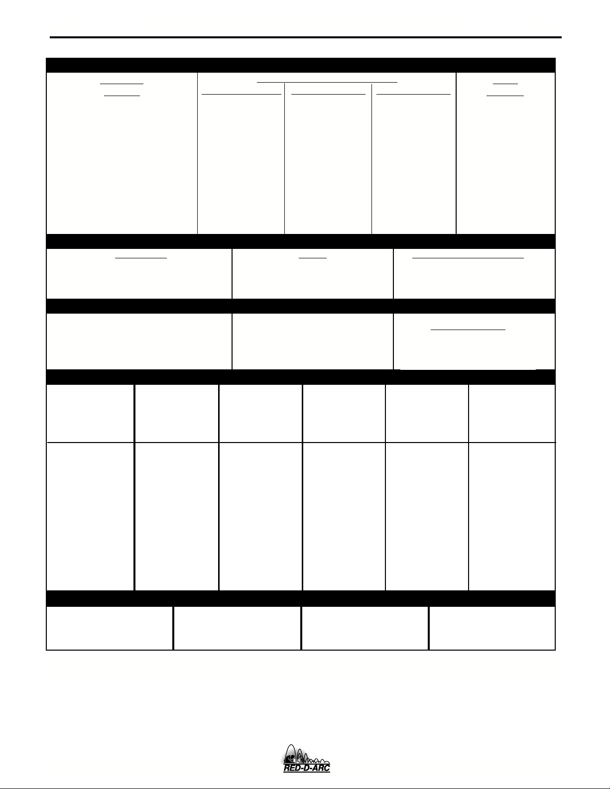
TECHNICAL SPECIFICATIONS – DC-600
INPUT - THREE PHASE ONLY
Standard
Volatge
100% Duty Cycle
Input Current at Rated Output
60% Duty Cycle
50% Duty Cycle
A-1
Code
Number
230/460/575/60
Duty Cycle
100% Duty Cycle
60% Duty Cycle
50% Duty Cycle
Output Range
70A/13V-780A/44V (CV)
90A/24V-780A/44V (CC)
INPUT
VOLTAGE /
FREQUENCY
230
460
575
108/54/43
122/61/49
134/67/54
RATED OUTPUT
Amps
600
680
750
Volts at Rated Amperes
OUTPUT
Maximum Open Circuit Voltage
72V
See the OPERATION section
RECOMMENDED INPUT WIRE AND FUSE SIZES
HERTZ
60
60
60
INPUT AMPERE
RATING ON
NAMEPLATE
108
54
43
TYPE 75°C
COPPER WIRE
IN CONDUIT
AWG(IEC-MM2) SIZES
30°C (86°F) Ambient
2 (34)
6 (14)
8 (8.4)
TYPE 75°C
GROUND WIRE
IN CONDUIT
AWG(IEC-MM2) SIZES
6 (14)
8 (8.4)
8 (8.4)
10650
44
44
44
Auxiliary
for Auxiliary Power
information by model
Power
TYPE 75°C
(SUPER LAG)
OR BREAKER
SIZE (AMPS)
175 Amp
90 Amp
70 Amp
1
PHYSICAL DIMENSIONS
HEIGHT
30.75 in
781 mm
1
Also called “inverse time” or “thermal/magnetic” circuit breakers; circuit breakers which have a delay in tripping action that decreases as the magnitude of the current increases.
WIDTH
22.25 in
567 mm
DEPTH
39.0 in
988 mm
DC-600
WEIGHT
522 lbs.
237 kg.
Page 10
A-2
INSTALLATION
A-2
Read entire Installation Section before installing
the DC-600.
SAFETY PRECAUTIONS
WARNING
ELECTRIC SHOCK CAN KILL.
• Only qualified personnel should
install this machine.
• Turn the input power OFF at the
disconnect switch or fuse box before
working on the equipment.
• Do not touch electrically hot parts.
• Always connect the IDEALARC
DC-600 grounding terminal to a good
electrical earth ground.
• Set the DC-600 Power ON/OFF PUSH BUTTON to the OFF
position when connecting power cord to input power.
__________________
SELECT PROPER LOCATION
Place the welder where clean cooling air can freely
circulate in through the front louvers and out through
the rear louvers. Dirt, dust or any foreign material that
can be drawn into the welder should be kept at a minimum. Failure to observe these precautions can result
in excessive operating temperatures and nuisance
shut-downs.
TILTING
The DC-600 must be placed on a stable, level surface
so it will not topple over.
DC-600
Page 11
A-3
INSTALLATION
A-3
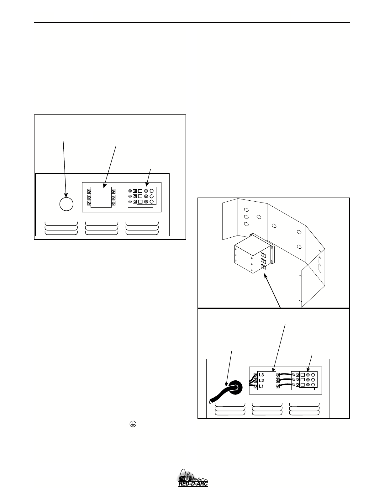
ELECTRICAL INPUT CONNECTIONS
Before installing the machine check that the input supply voltage, phase, and frequency are the same as the
voltage, phase, and frequency as specified on the
welder Rating Plate located on the Case Back
Assembly. Input power supply entry is through the
hole in the Case Back Assembly. See Figure A.1 for
the location of the machine’s input cable entry opening, Input Contactor (CR1), and reconnect panel
assembly for dual voltage machines.
INPUT SUPPLY
CABLE ENTRY
OPENING
CONTACTOR (CR1)
INPUT
RECONNECT
PANEL ASSEMBLY
INPUT POWER SUPPLYCONNECTIONS
A qualified electrician should connect the input power
supply leads.
1. Follow all national and local electrical codes.
2. Use a three-phase line.
3. Remove Input Access Door at upper rear of
machine.
4. Follow Input Supply Connection Diagram located
on the inside of the door.
5. Connect the three phase AC power supply
leadsL1,L2,and L3 to the input contactor
terminals in the Input Box Assembly by passing
them thru the three aligned .50” diameter holes in
the baffle and tighten them in the terminal connectors. Be sure to close the baffle by inserting the
tab into the slot in the baffle. See Figure A.2.
FIGURE A.1 - Rear Panel
FUSE AND WIRE SIZES
Protect the input circuit with the super lag fuses or
delay type circuit breakers listed on the Technical
Specifications page of this manual for the machine
being used. They are also called inverse time or thermal/magnetic circuit breakers.
DO NOT use fuses or circuit breakers with a lower
amp rating than recommended. This can result in “nuisance” tripping caused by inrush current even when
machine is not being used for welding at high output
currents.
Use input and grounding wire sizes that meet local
electrical codes or see the Technical Specifications
page in this manual.
GROUND CONNECTION
Ground the frame of the machine. A ground
terminal marked with the symbol ( ) is located inside
the Case Back of the machine near the input contactor. Access to the Input Box Assembly is at the upper
rear of the machine. See your local and national electrical codes for proper grounding methods.
INPUT
CONTACTOR (CR1)
INPUT POWER SUPPLY
CABLE WITH BUSHING
OR BOX CONNECTOR
RECONNECT
PANEL ASSEMBLY
FIGURE A.2 - Input Power Supply
Connections
DC-600
Page 12
A-4
INSTALLATION
A-4
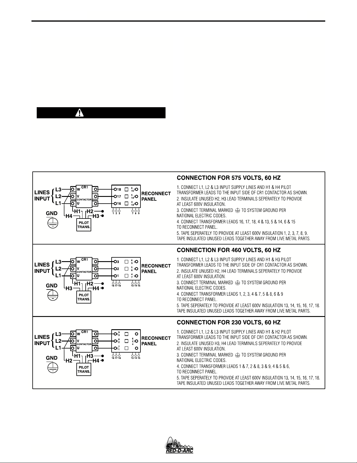
RECONNECT PROCEDURE
Multiple voltage machines are shipped connected to
the highest input voltage listed on the machine’s rating
plate. Before installing the machine, check that the
Reconnect Panel in the Input Box Assembly is connected for the proper voltage.
CAUTION
Failure to follow these instructions can cause immediate failure of components within the machine.
__________________
To reconnect a multiple voltage machine to a different
voltage, remove input power and change the position
of the reconnect board on the Reconnect Panel.
Follow The Input Connection Diagram located on the
inside of Case Back Input Access Door. This connection diagram for the following code is shown below.
1. For 230/460/575, see Figure A.3. (M15666)
FIGURE A.3-Reconnect Panel Board Positions for 230/460/575 VAC Machines
DC-600
Page 13
A-5
INSTALLATION
OUTPUT CONNECTIONS
See Table A.1 for recommended DC-600 cable sizes for combined lengths of electrode and work cables.
TABLE A.1
DC-600 Cable Sizes for Combined Lengths of Copper Electrode and Work Cable
at 100% Duty Cycle
Cable SizeParallel CablesCable Length
2
Lengths up to 150 ft. (46m)
1/0 (53mm
2
2
2/0 (85mm
3/0 (107mm
)2
2
)150 ft.(46m) to 200 ft (61m)
2
)200 ft.(61m) to 250 ft.(76m)
A-5
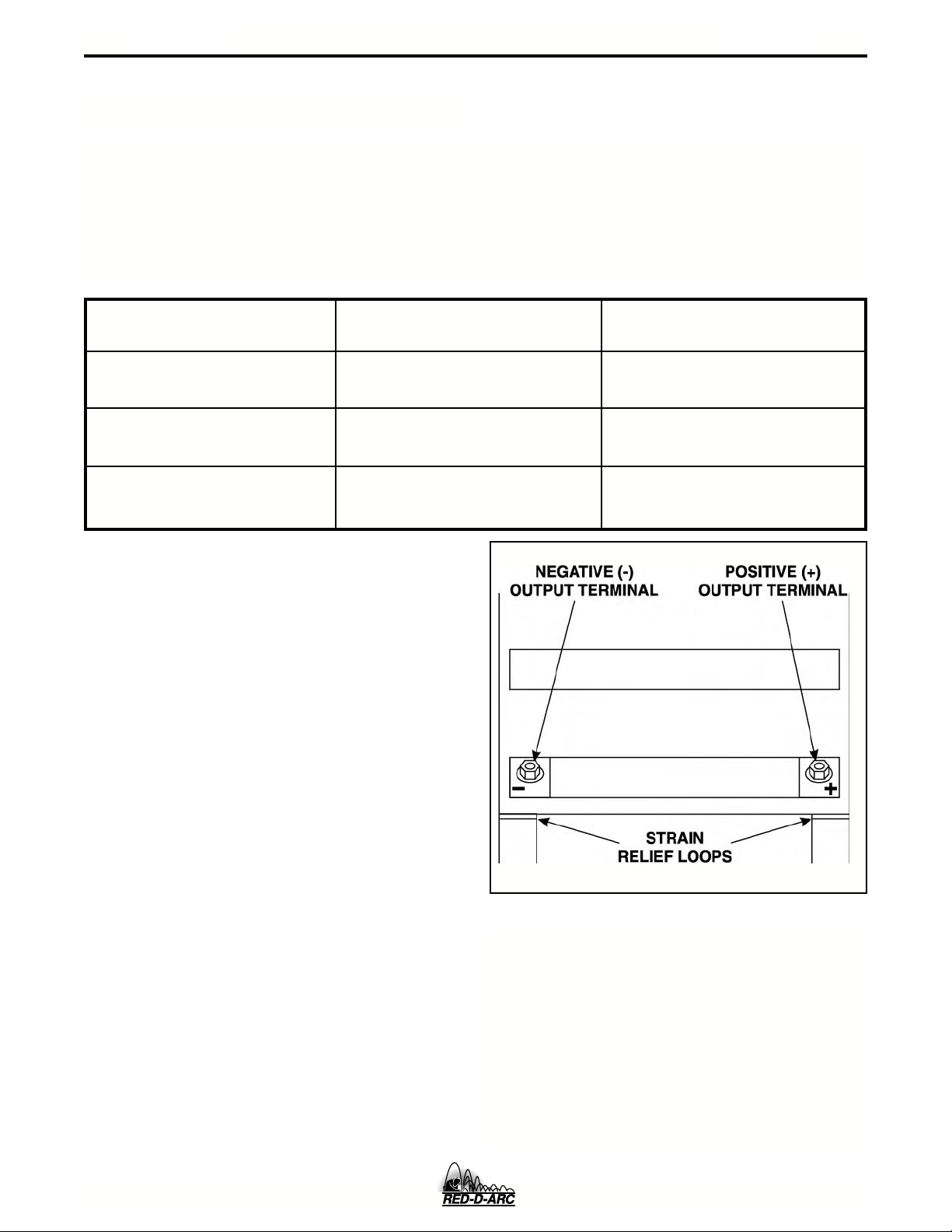
ELECTRODE,WORK AND #21 LEAD
CONNECTIONS
A. Connect Electrode and Work Leads to
Output Terminals.
1. Set the ON/OFF toggle switch to OFF.
2. Locate the retractable strain relief loops directly
below the output terminals in the lower right and
lower left corners of the Case Front Assembly.
See Figure A.4.
3. Pull out the retractable strain relief loops.
4. Insert the electrode lead through the loop directly
below the desired polarity (positive or negative).
Pull through enough cable to reach the output
terminals.
5. Connect electrode lead to the desired terminal
(positive/negative).
6. Tighten the output terminal nut with a wrench.
7. Connect the work lead to the other output
terminal following steps 4-6.
FIGURE A.4 - Output Terminals.
B. Connect #21 Work Sense Lead to Proper
Terminal
There are two work sense lead connection points (+21
and -21) on terminal strip (T.S.2) located behind the
hinged access panel on the right side of the case
front. See 14 Pin MS Type Receptacle section or
Terminal Strip Section for connection procedure.
DC-600
Page 14
A-6
F=76
G=75
H=21
I=41
J=31
K=42
A=32
B=GND
C=2
D=4
E=77
LN
M
INSTALLATION
A-6
AUXILIARY POWER AND
CONTROL CONNECTIONS
Located at the left side of the front of the welder
behind a hinged cover is a 115VAC duplex receptacle
for auxiliary power (60 Hertz Models only). On the
right side of the case front is a 14 Pin MS type receptacle for connection of auxiliary equipment such as
wire feeders. Also, terminal strips with 115VAC and
connections for auxiliary equipment are located
behind the hinged access panel on the right side of
the case front. (see Auxiliary Power Table for details)
AUXILIARY POWER TABLE
Voltage and Circuit Breaker Ratings at Auxiliary Power
Connections for Various Models
Auxiliary 60 Hz
Power Models
Connections
At Duplex 115V 15A
Receptacle
Terminal strip 115V 15A
terminals 31 & 32
MS-Receptacle 115V 15A
pins A & J
MS-Receptacle 42V 10A
pins I & K
115VAC DUPLEX RECEPTACLE (60 HERTZ
MODELS ONLY)
PIN LEAD NO. FUNCTION
A 32 115 VAC
B GND Chassis Connection
C 2 Trigger Circuit
D 4 Trigger Circuit
E 77 Output Control
F 76 Output Control
G 75 Output Control
H 21 Work Sense Connection
I 41 42 VAC
J 31 115 VAC
1.
K 42 42 VAC
L --- --M --- --N --- ---
TERMINAL STRIPS
Terminal strips are available behind the cover on the
case front to connect wire feeder control cables that
do not have a 14 Pin MS-type connector. These terminals supply the connections as shown in the following
Terminal Strip charts. NOTE: There are two work
sense lead connection points on the terminal strip.
Connect both the work sense lead #21 from the 14 pin
connector and #21 lead of the control cable to “-21”
when welding positive polarity or to “+21” when welding negative polarity.
2
The 115VAC duplex receptacle is protected by a circuit breaker located on the nameplate. The receptacle
is a NEMA 5-15R.
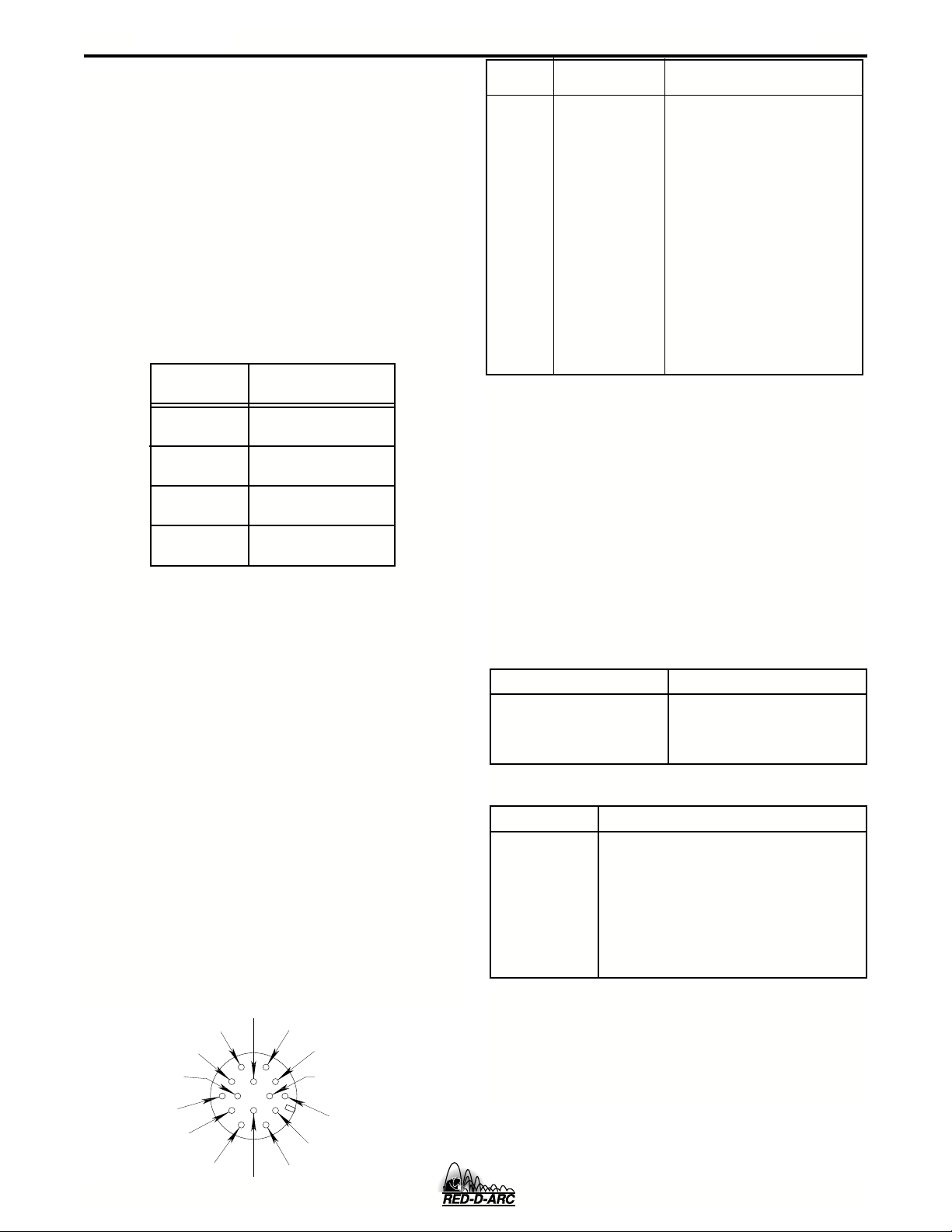
14 PIN MS TYPE RECEPTACLE
(For MS3106A-20-27PX Plug. L.E.C. Part #S12020-32)
Refer to the figure A.5 for the available circuits in the
14 pin receptacle.
42 VAC is available at receptacle pins I and K.
A 10 amp circuit breaker protects this circuit.
115 VAC is available at receptacle pins A and J (All
Models). A 15 amp circuit breaker protects this circuit.
Note that the 42 VAC and 115 VAC circuits are electrically isolated from each other.
FIGURE A.5 FRONT VIEW OF 14-PIN
CONNECTOR RECEPTACLE
TERMINAL STRIP 1 (T.S.1)
Lead No. Function
75 Output Control
76 Output Control
77 Output Control
TERMINAL STRIP 2 (T.S.2)
Lead No. Function
+21
-21
41 42 VAC
4 Trigger Circuit
2 Trigger Circuit
31 115 VAC
32 115 VAC
1.
115VAC circuit is on all models.
2.
As shipped from the factory Lead #21 from the 14 Pin connector is
connected to “-21” on the terminal strip (T.S.2). This is the configuration for positive welding. If welding negative polarity, connect
lead #21 to the “+21” connection point on the terminal strip
(T.S.2).
Work Connection (Electrode Negative)
Work Connection (Electrode Positive)
1
1
2
DC-600
Page 15
B-1
OPERATION
OPERATING INSTRUCTIONS
Read and understand entire section before operating machine.
SAFETY PRECAUTIONS
WARNING
ELECTRIC SHOCK
can kill.
• Do not touch electrically live parts
or electrode with skin or wet
clothing.
• Insulate yourself from work and
ground.
B-1
• Always wear dry insulating
gloves.
FUMES AND GASES
can be dangerous.
• Keep your head out of fumes.
• Use ventilation or exhaust to
remove fumes from breathing
zone.
WELDING, CUTTING and
GOUGING SPARKS
can cause fire or explosion
• Keep flammable material away.
• Do not weld, cut or gouge on
containers that have held combustibles.
ARC RAYS
can burn.
• Wear eye, ear and body
protection.
Observe additional Safety Guidelines detailed in
the beginning of this manual.
DC-600
Page 16

B-2
OPERATION
B-2
GENERAL DESCRIPTION
The DC-600 is an SCR controlled three phase welding
and cutting power source. It uses a single range
potentiometer to control:
• Submerged Arc Semi-Automatic or Automatic
Welding
• Open Arc Semi-Automatic or Automatic Welding
• Stick Welding
• Air/Carbon Arc Cutting (Carbon Rod Sizes up to
3/8” Diameter)
The DC-600 has a three-position Welding Mode
Switch to enable the user to operate in one of three
modes:
• Constant Current (CC) Stick (also used for AAC)
• Constant Voltage (CV) Submerged Arc
• Constant Voltage (CV) Innershield (also used for
GMAW)
The optional Multi-Process Switch allows the user to
switch between semi-automatic or automatic welding
and stick welding or air/carbon arc cutting without disconnecting the wire feeder equipment control, electrode,and work leads.
RECOMMENDED PROCESSES AND
EQUIPMENT
The DC-600 is designed for GMAW (MIG), FCAW,
and submerged arc (SAW) within the capacity of the
machine. It can also be used for stick welding
(SMAW) and for air carbon arc (AAC) cutting with carbon rods up to 3/8" diameter.
The DC-600 is provided with a three position mode
switch that selects CV Innershield, CV Submerged
Arc, or CC Stick.
The DC-600 can be easily connected to wire feeding
equipment, including:
• Semi-automatic wire feeders LN-7, LN-7 GMA,
LN-742, LN-8, LN-9, LN-9 GMA, LN- 10, LN-23P,
LN-25, and DH-10.
• Automatic wire feeders NA-3, NA-5, and NA-5R.
• Tractors LT-56 and LT-7
DESIGN FEATURES AND
ADVANTAGES
• Excellent arc characteristics for optimum constant
voltage submerged arc and Innershield welding
performance.
• A control circuit designed to provide good starting
for a large variety of processes and procedures.
• Output Control Potentiometer that provides easy
single range continuous control.
• Output Control Switch that provides simple switching from local to remote control.
• Output Terminals Switch to energize output terminals either local or remote.
• Red neon pilot light to confirm that the Input
Contactor is energized.
• DC Ammeter and Voltmeter
• 42VAC 10 Amp auxiliary power available for the
wire feeder, circuit breaker protected.
• Single MS-type (14 pin) connector for wire feeder.
• 115VAC 15 Amp auxiliary power available for the
wire feeder, circuit breaker protected.
• 115VAC 15 Amp duplex plug receptacle available
on 60 Hertz models, circuit breaker protected.
• Multi-functional terminal strip for easy connection
of wire feeding control cables.
• Recessed output terminals to avoid any person or
object from accidentally coming into contact with
the output terminals and labeled " + " and " - " for
easy identification.
• Thermostatically protected power source.
• Electronic protection circuit to protect power
source against overloads.
• Input line voltage compensation to provide an
essentially constant output.
• SCR electronically controlled welder output provides extra long life, especially for highly repetitive
welding applications.
• Solid state 2 and 4 circuit for extra long life.
• Two circuit solid state control system provides
maximum performance and circuit protection.
• Low profile case provides maximum use of space.
• Convenient access to all controls.
• Output lead strain relief loops to prevent terminal
and cable damage.
• Easily removed case side.
• Outdoor operation because enclosure is designed
with air intake louvers that keep dripping water
from entering the unit. Transformer, SCR bridge,
and choke have special corrosion resistant paint
for added protection.
DC-600
Page 17

B-3
OPERATION
WELDING CAPABILITY
The DC-600 has the following Output and Duty Cycle based on operation for a 10 minute period:
600 Amps, 44 Volts at 100%
680 Amps, 44 Volts at 60%
750 Amps, 44 Volts at 50%
MEANINGS OF GRAPHICAL SYMBOLS ON CASE FRONT
B-3
Input POWER ON/OFF Switch
SYMBOL
MEANING
INPUT POWER
Pilot Light
Input power on when light is illuminated
(except for abnormal conditions).
Always indicates POWER ON/OFF
switch is in ON position.
OUTPUT CONTROL
ON
OFF
LOCAL/REMOTE Switch
SYMBOL
Control Of Output Voltage and
Current is Via DC-600's Control Dial
Remote Control of Output Voltage
MODE Switch
CC STICK: Shielded Metal Arc
Welding (SMAW), this switch
position is also used for Air
Carbon Arc Cutting (AAC)
CV SUBMERGED ARC:
Constant Voltage Submerged
Arc Welding (SAW)
CV INNERSHIELD: Flux Cored
Arc Welding (FCAW), this switch
position is also used for Gas
Metal Arc Welding (GMAW).
MEANING
and Current
OUTPUT VOLT AGE
AND CURRENT
Clockwise Increase of Output
Voltage and Current
TERMINALS ON/REMOTE Switch
OUTPUT TERMINALS
ENERGIZED
Remote Control of Output Terminals
(Energized or Non-Energized)
Output T erminal Connections
Positive Output Terminal
Negative Output Terminal
WARNING Identification
Warning and Caution Identification
Circuit Breaker
Circuit Breaker (two breakers: 15A
for 115V circuit and 10A for 42V
circuit)
DC-600
Page 18

B-4
NEMA EW 1 (100%)
OPERATION
MEANING OF GRAPHICAL SYMBOLS ON
RATING PLATE (LOCATED ON CASE BACK)
Designates welder complies with
National Electrical Manufacturers
Association requirements EW 1
Class I with 100% duty cycle at
600Amps output.
Three Phase Input Power
3 Phase transformer with rectified
DC output
Line Connection
NRTL/C
Shielded Metal Arc Welding (SMAW)
Submerged Arc Welding (SAW)
Designates welder complies with
R
both Underwriters Laboratories (UL)
standards and Canadian Standards
Association (CSA) standards. (60
Hertz Models)
B-4
Gas Metal Arc Welding (GMAW)
Flux Cored Arc Welding (FCAW)
MEANING OF GRAPHICAL SYMBOL FOR GROUND CONNECTION
Signifies the equipment connection
point for the protective earth ground
DC-600
Page 19

B-5
OPERATION
B-5
CONTROLS AND SETTINGS
All operator controls and adjustments are located on the Case Front Assembly of the DC-600. See Figure B.1 for
the location of each control.
7
5
3
6
8
5
6
4
7
3
8
2
9
1
10
DC-600
12
FIGURE B.1 - CONTROL PANEL KEYS
49
1
2
11
10
13
1. Input POWER ON/OFF Switch
This toggle switch turns the machine on or off.
Putting the switch in the ON “ ” position energizes the machine’s input contactor applying input
power to the machine. Switching the switch to the
OFF “ ” position de-energizes the input
contactor.
2. POWER Light
When the POWER switch is in the ON position the
machine’s red POWER light will illuminate. If the
input contactor de-energizes the machine in an
abnormal situation the pilot light will still illuminate.
In this situation it may be necessary to reset the
machine by switching the POWER switch to the
OFF and then to the ON position. (See Overload,
Overcurrent, and Fault Protection Section)
3. OUTPUT CONTROL
This control provides continuous control of the
machine’s output voltage and current from minimum to maximum (typical full pot range between
15 to 44 volts and 90 to 750 amps) as it is rotated
clock-wise. Voltage or current control is determined by setting of Mode Switch (CV or CC).
4. OUTPUT TERMINALS ON/REMOTE Switch
When this switch is in the REMOTE “ ” position, the DC-600’s output terminals will be electrically “cold” until a remote device such as a wire
feeder closes the #2 and #4 circuit in the MSreceptacle or terminal strip (T.S.2). When this
switch is in the ON “ ” position the machine’s
output terminals will be electrically energized all
the time.
5. LOCAL/REMOTE Switch
When this switch is set to the LOCAL “ “ position, control of the output voltage and current is via
the OUTPUT CONTROL on the DC-600’s control
panel. When this switch is set to the REMOTE
“ ” position, control is through a remote source
such as a wire feeder via the #75, #76, and #77
leads in the MS-receptacle or terminal strip
(T.S.1).
DC-600
Page 20

B-6
OPERATION
B-6
6. Mode Switch
This switch allows for selecting the welding
process to be used:
CC STICK-for SMAW and AAC
CV SUBMERGED ARC- for SAW
CV INNERSHIELD- for FCAW and GMAW
7. 115VAC Duplex Receptacle (60 Hertz Models)
This receptacle provides up to 15 amps of 115
VAC auxiliary power.
8. 115VAC 15 Amp Circuit Breaker
This breaker protects the 115 VAC auxiliary circuits located in the duplex receptacle, terminal
strip (T.S.2) and MS-receptacle.
9. 42VAC 10 Amp Circuit Breaker
This breaker protects the 42VAC auxiliary circuits
located in the terminal strip (T.S.2) and MS-receptacle.
10.14 Pin MS-Receptacle
This connector provides easy connection for a wire
feeder control cable. It provides connections for
auxiliary power, output switching, remote output
control, wire feeder voltmeter sense lead and
ground. Refer to 14 Pin MS Type Receptacle in the
Installation Section for information about the circuits made available at this receptacle.
11.Terminal Strip Cover Panel
Rotate this panel to gain access to the circuits
made available at the two terminal strips (T.S.1
and T.S.2). These terminal strips contains the
same circuits as the 14 pin MS-receptacle. There
is a box connector adjacent to this cover for routing
leads to the terminal strips.
AUXILIARY POWER IN MS-RECEPTACLE
42 volt AC auxiliary power, as required for some wire
feeders, is available through the wire feeder MSreceptacle. A 10 amp circuit breaker protects the 42
volt circuit from overloads.
DC-600 machines can also supply 115 volt AC auxiliary power through the wire feeder receptacle. A 15
amp circuit breaker protects the 115 volt circuit from
overloads.
OVERLOAD, OVERCURRENT, AND
FAULT PROTECTION
This welder has thermostatic protection from excessive duty cycles, overloads, loss of cooling, and high
ambient temperatures. When the welder is subjected
to an overload or loss of cooling, a thermostat will
open. The input contactor will open and remain open
until the machine cools; the red POWER light stays
illuminated. No welding is possible during this cool
down period. The machine will reset automatically
when the thermostat cools.
The power source is also protected against overcurrents in the SCR bridge assembly through an electronic protection circuit. This circuit senses currents
over 780 amps on the power source and opens the
input contactor should the overcurrent remain for a
predetermined time (the red POWER light stays illuminated). The predetermined time varies with the
amount of overcurrent; the greater the overcurrent,
the shorter the time. The input contactor will remain
open until the power source is manually started by
resetting the POWER ON/OFF toggle switch.
12.Negative Output Terminal
This output terminal is for connecting a welding
cable. To change welding polarity and for proper
welding cable size refer to Electrode and Work
Cables in the Installation Section.
13.Positive Output Terminal
This output terminal is for connecting a welding
cable. To change welding polarity and for proper
welding cable size refer to Electrode and Work
Cables in the Installation Section.
The power source circuitry is protected from faults on
leads 75, 76, or 77. If any of these leads are connected to either the positive or negative output leads, the
DC-600 will either shut down completely (input contactor opens and red POWER light stays illuminated),
or will operate at minimum output thus preventing any
damage to the DC-600. If DC-600 shuts down, it must
be manually started by resetting the POWER ON/OFF
toggle switch.
DC-600
Page 21

B-7
OPERATION
B-7
OPERATING STEPS
The following procedures are for using the DC-600 in
the local control mode of operation. For remote control of the machine, see the Remote Control of
Machine Operation section.
Before operating the machine, make sure you have all
materials needed to complete the job. Be sure you
are familiar with and have taken all possible safety
precautions before starting work. It is important that
you follow these operating steps each time you use
the machine.
1. Turn on the main AC power supply to the
machine.
2. Connect the #21 work lead to either + or - on terminal strip (T.S.2).
3. Set the Welding Mode switch to welding process
being used:
• CC STICK (for SMAW and AAC)
• CV SUBMERGED ARC (for SAW)
• CV INNERSHIELD (for FCAW and GMAW)
4. Turn the POWER ON/OFF Toggle Switch to the
“ON” position
• The red pilot light glows.
• The fan starts.
5. Set OUTPUT CONTROL Potentiometer to desired
voltage or current.
6. Set the OUTPUT TERMINALS switch to either
“ON” ( output terminals energized) or “REMOTE”
(output terminals energized when #2 and #4
closed by remote device such as wire feeder)
REMOTE CONTROL OF MACHINE
OPERATION
The toggle switch on the control panel labeled
“Remote - Panel” gives the operator the option of controlling the machine output from a remote location. If
in the Remote position a wire feeder with remote control capabilities or a remote control device such as a
K775 must be connected to terminals 75, 76, and 77.
Refer to Accessories Section for wire feeder remote
information.
WELDING PROCEDURE
RECOMMENDATIONS
Select Welding Mode Switch position based on type of
welding to be done.
1. Innershield Welding (FCAW)/MIG (GMAW)
Welding: Use the CV INNERSHIELD mode.
2. Submerged Arc Welding (SAW): Use the CV
SUBMERGED ARC mode. If performing high
speed welding, switch between the CV
Submerged Arc and the CV Innershield mode and
use the mode that produces the best welding
results.
3. Air/Carbon Arc Cutting (AAC) / Stick Welding
(SMAW) / High Current, Large Puddle Submerged
Arc Welding (SAW): Use the CC STICK mode.
When the DC-600 is used for Air/Carbon Arc cutting, the OUTPUT CONTROL potentiometer
should be set to "9" initially. Based on the size of
the carbon being used or the process, turn the
potentiometer to a lower setting as required by the
process. You can use carbon rods up to 3/8" in
diameter at currents as high as 750 amps with
excellent arc control. The welder protection circuit
protects the machine from extremely high short
circuiting pulses.
7. Make the weld.
DC-600
Page 22

B-8
OPERATION
B-8
SEMI-AUTOMATIC AND AUTOMATIC
WIRE FEEDING WITH THE DC-600
AND WIRE FEEDERS
When using the DC-600 with semi-automatic or automatic wire feeding equipment and for stick welding or
air/carbon arc cutting, it is recommended that the
optional MULTI-PROCESS SWITCH be used. This
switch permits you to easily change the polarity of the
connected wire feeding equipment or switch to stick
welding or air/carbon arc cutting.
NA-3 AUTOMATIC WIRE FEEDER
1. Set the DC-600 LOCAL/REMOTE Switch to
REMOTE. Set the OUTPUT TERMINALS switch
to REMOTE. NOTE: Later model NA-3 automatic
wire feeders are capable of cold starts when the
NA-3 Mode switch is in the CV or CC mode position. Some earlier models are capable of cold
starting only in the CC mode position. Cold starting enables you to inch the wire down to the work,
automatically stop, and automatically energize the
flux hopper valve.
2. Set the DC-600 welding mode switch for the
desired process: CV SUBMERGED ARC, CV
INNERSHIELD mode or CC STICK mode.
2. Set the NA-3 Open Circuit Voltage Control to the
same dial setting as the Arc Voltage Control. If
this is a new welding procedure, a good starting
point is to set the Open Circuit Voltage Control to
# 6.
NOTE: The open circuit voltage of the
DC-600 varies from approximately 16 volts to 56
volts in the CV INNERSHIELD or CV
SUBMERGED ARC modes. The open circuit voltage is constant in the CC STICK mode.
3. Run a test weld. Set proper current, voltage, and
travel speed.
a. For the best starting performance, the NA-
3 Open Circuit Voltage Control and Voltage
Control setting should be the same. Set the
Inch Speed Control for the slowest inch
speed possible.
b. To adjust the Open Circuit Voltage Control to
get the best starting performance, make
repeated starts observing the NA-3 voltmeter.
When the voltmeter pointer swings smoothly up to
the desired arc voltage, without undershooting or
overshooting the desired arc voltage, the Open
Circuit Voltage Control is set properly.
3. Set the NA-3 mode Switch Position to either CV or
CC to match the DC-600 mode selected in step 2.
4. Refer to the NA-3 operators manual for instructions on how to use the NA-3 in conjunction with
the DC-600.
5. Follow the following guidelines for good arc striking detailed below for each welding mode.
GOOD ARC STRIKING GUIDELINES FOR THE NA3 WITH THE DC-600 IN THE CV INNERSHIELD, CV
SUBMERGED ARC OR CC STICK WELDING
MODES.
Following are some basic arc striking techniques that
apply to all wire feed processes. Using these procedures should provide trouble-free starting. These procedures apply to single, solid wires and Innershield
wires.
1. Cut the electrode to a sharp point.
If the voltmeter pointer overshoots the desired
voltage and then returns back to the desired voltage, the Open Circuit Voltage Control is set too
high. This can result in a bad start where the wire
tends to "Blast off."
If the voltmeter pointer hesitates before coming up
to the desired voltage, the Open Circuit Voltage
Control is set too low. This can cause the electrode to stub.
4. Start and make the weld.
a. Cold starts. For cold starts, be sure the work
piece is clean and the electrode makes positive contact with the work piece.
b. Hot "On the Fly" starts. For hot starts, travel
should begin before the wire contacts the
work piece.
DC-600
Page 23

B-9
OPERATION
B-9
ARC STRIKING WITH DC-600 AND THE NA-3
START BOARD
When electrical strikeouts exceed 1 3/4” (44.4mm) an
NA-3 Start Board may be required to improve arc
striking.
When the NA-3 Start Board is used to improve arc
striking, use the following procedures:
1. Set start time at 0.
2. Set NA-3 start current and start voltage at midrange.
3. Set the NA-3 output current and voltage to the
proper settings for the welding procedure to be
used.
4. Turn the Start Board Timer to maximum.
5. Set Start Board current and voltage control.
a. Set the Start Board current control to 1 1/2
dial numbers below that set on the NA-3 current control.
b. Set the Start Board voltage control equal with
the NA-3 voltage control setting.
NOTE: These Start Board current and voltage
settings result in a start up current that is lower
than the NA-3 current setting and approximately
equal with the NA-3 voltage setting for the desired
welding procedure.
6. Establish the correct arc striking procedure with
the NA-3 Start Board timer set at maximum.
a. For the best starting performance, the NA-3
Open Circuit Voltage Control and Voltage
Control setting should be the same. Set the
Inch Speed Control for the slowest inch
speed possible.
b. To adjust the Open Circuit Voltage Control to
get the best starting performance, make
repeated starts observing the NA-3 voltmeter.
When the voltmeter pointer swings smoothly up to
the desired arc voltage, without undershooting or
overshooting the desired arc voltage, the Open
Circuit Voltage Control is set properly.
If the voltmeter pointer overshoots the desired
voltage and then returns back to the desired voltage, the Open Circuit Voltage Control is set too
high. This can result in a bad start where the wire
tends to "Blast off."
If the voltmeter pointer hesitates before coming up
to the desired voltage, the Open Circuit Voltage
Control is set too low. This can cause the electrode to stub.
c. Set NA-3 Start Board current and voltage as
close to the welding procedure current and
voltage as possible.
NOTE: The Start Board current and voltage
should be as close as possible to the welding procedure current and voltage, while still getting satisfactory starts.
d. Set the start time to as low a time as possible
while still getting satisfactory starts.
7. Start and make the weld.
DC-600
Page 24

B-10
OPERATION
B-10
DC-600 POWER SOURCE SETTING WHEN
CONNECTED TO NA-5 WIRE FEEDER
When using the DC-600 with the NA-5 wire feeder, set
the controls on the DC-600 as follows for the best performance:
1. Turn OFF main AC input power supply to the DC-
600.
2. Connect the electrode cables to terminal polarity
to be used.
3. Connect the #21 work lead (on T.S.2) to the
same polarity as the work cable connection.
4. Set the DC-600 LOCAL/REMOTE Switch to
REMOTE.
5. Set the DC-600 OUTPUT TERMINALS switch to
REMOTE.
6. Set the DC-600 WELDING MODE SWITCH to the
position that matches the welding process being
used.
a. For submerged arc welding, set WELDING
MODE SWITCH to CV SUBMERGED ARC
position.
b. For all open arc welding processes set
WELDING MODE SWITCH to CV INNERSHIELD position.
LN-8 SEMI-AUTOMATIC WIRE FEEDER
To use the LN-8 Semi-Automatic Wire Feeder with
DC-600
1. Set the DC-600 WELDING MODE SWITCH to
either CV INNERSHIELD mode or CV
SUBMERGED ARC mode depending on the welding process being used.
2. Set the DC-600 LOCAL/REMOTE SWITCH to the
REMOTE position.
3. Set the DC-600 OUTPUT TERMINALS switch to
REMOTE.
4. Set the LN-8 Welding Mode Switch to the CV position. The LN-8 Welding Mode Switch is located
on the variable voltage (CC) board.
5. Refer to the LN-8 Operator’s Manual for instructions on how to use the LN-8.
LN-7 AND LN-9 SEMI-AUTOMATIC WIRE
FEEDERS OR OTHER CONSTANT WIRE
FEEDERS
To use the LN-7, LN-9, or other constant wire feed
speed semi-automatic wire feeders with DC-600
1. Set the DC-600 WELDING MODE SWITCH to
either CV INNERSHIELD mode or CV
SUBMERGED ARC mode depending on the welding process being used.
NOTE: These semi-automatic wire feeders cannot be used in the CC Stick mode.
2. Set the DC-600 LOCAL/REMOTE SWITCH.
a. LN-7: Use either an optional K775 Remote
Control Box Assembly or set the
DC-600 LOCAL/REMOTE SWITCH in the
Local position.
b. LN-9: Refer to the LN-9 Operator’s Manual for
instructions of how to use the LN-9.
c. Other Constant Wire Feeders: Refer to Wire
Feeders Operator’s Manual.
3. Set the DC-600 OUTPUT TERMINALS switch to
REMOTE.
DC-600
Page 25

C-1
STRAIGHT PLUG (14 PIN)
TO POWER SOURCE
CABLE RECEPTACLE (6 SOCKET)
CABLE RECEPTACLE (14 SOCKET)
TO: K857 REMOTE CONTROL
TO: LN-7 WIRE FEEDERS
ACCESSORIES
C-1
WIRE FEEDERS AND TRACTORS
The DC-600 can be used to power any of the following Wire Feeders and Tractors:
Semi-Automatic Wire Feeders:
DH-10 LN-9
LN-7 LN-9 GMA
LN-7 GMA LN-23P
LN-742 LN-25
LN-8 LN-10
Automatic Wire Feeders:
NA-3 NA-5R
NA-5
Tractors:
LT-7 LT-56
FIELD INSTALLED OPTIONS
Remote Output Control (K775 or K857
with K864 Adapter)
An optional “remote out control” is available. The
K775 is the same remote control that is used on other
Lincoln power sources. The K775 consist of a control
box with 28 feet (8.5mm) of four conductor cable. This
connects to terminals 75,76, and 77 on the terminal
strip (T.S.1) and the case grounding screw so marked
with the symbol “” on the machine. These termi-
nals are located behind the hinged cover on the case
front. This control will give the same control as the
output control on the machine.
Undercarriages (K817P, K842)
For easy moving of the machine, optional undercarriages are available with polyolefin wheels (K817P) or
a platform undercarriage (K842) with mountings for
two gas cylinders at rear of welder.
Paralleling Kit (K1611-1)
Permits paralleling of two DC-600's for welding currents of up to 1200 amps, 100% duty cycle.
Tig Module (K930-2)
Portable high frequency generator for AC/DC TIG
welding.
FACTORY OR FIELD INSTALLED
OPTIONS
Multi-Process Switch (K804-1)
The MULTI-PROCESS SWITCH gives you the ability
to:
• Switch between "stick welding or air/carbon arc
cutting" and using a semi-automatic or automatic
wire feeder.
• Change the polarity of a semi-automatic or auto-
matic wire feeder without changing any electrical
cable connections.
See Figure C.1
The K857 is similar to the K775, except the K857 has
a 6-pin MS-style connector. The K857 requires a
K864 adapter cable which connects to the 14-pin connector on the case front.
Remote Control Adapter Cable (K864)
A "V" cable 12" (.30 m) long to connect a K857
Remote Control (6-pin connector) with an LN-7 wirefeeder (14-pin connector) and the machine (14-pin
connector). If a remote control is used alone the wirefeeder connection is then not used.
+
-
–
WIRE
FEEDER
CABLES
FIGURE C.1 - MULTI-PROCESS SWITCH
DC-600
STICK OR
AIR
CARBON
ARC
+
STICK OR
AIR/CARBON
ARC CABLES
Page 26

C-2
ACCESSORIES
The MULTI-PROCESS SWITCH has two sets of output terminals. You connect the wire feeder unit cables
to the set of terminals on the left side of the box and
the stick or air/carbon arc cables to the set of terminals on the right side (facing the front of the machine)
as shown in Figure C.1. The output terminals are protected against accidental contact by hinged covers.
When the MULTI-PROCESS SWITCH is in the "Stick
or Air/Carbon Arc" position, only those
terminals are energized. The wire feeder nozzle or
gun and electrode are not electrically "hot" when in
this mode.
21-21+ 41 4 2 31 32
NEGATIVE (–)
OUTPUT
STUD
C-2
TERMINAL
STRIP COVER
BOX
CONNECTOR
75 76 77
CONTROL
LEADS
POSITIVE (+)
–
+
OUTPUT
STUD
Follow these steps to install the MULTI-PROCESS
SWITCH:
1. Confirm that the DC-600 POWER ON/OFF switch
is in the OFF position.
2. Disconnect main AC input power to the DC-
600.
3. Open the terminal strip hinged cover located on
the Case Front Assembly.
4. The MULTI-PROCESS SWITCH is mounted to
the case front with four 1/4” self-tapping screws.
The screw holes are 13.8” apart side to side and
4.5” apart top to bottom, Run one of the 1/4”
screws part way in and out of the screw holes to
open them up. Make sure that the two sleeved
control leads do not get pinched when hanging
the switch; route them out the side to the right of
the switch. Support the switch in position and start
the four screws, then tighten them.
5. Route the MULTI-PROCESS SWITCH control
leads through the strain-relief box connectors and
into the terminal strip. Connect wire feeder control
cable as specified in specific connection diagram
and make other terminal strip connections as
specified on the connection diagram for the
Lincoln wire feeder being used.
6. Connect the control leads from the MULTIPROCESS SWITCH to terminals #2 and #4 on
the DC-600's terminal strip.
7. Connect the right cable from the MULTIPROCESS SWITCH (facing the front of the
machine) to the DC-600 positive (+) output terminal. See Figure C.2.
+
ELECTRODE
CABLE
STICK AIR/CARBON
ARC WELDING
EQUIPMENT
WORK
CABLE
ELECTRODE
CABLE
WIRE
FEEDER
WORK
CABLE
WORK
ELECTRODES
(IF NEEDED
JUMPER
SEE INSTRUCTIONS)
FIGURE C.4 - MULTI-PROCESS SWITCH
CABLE CONNECTIONS.
8. Connect the left cable from the MULTI-PROCESS
SWITCH (facing the front of the machine) to the
DC-600 negative (-) output terminal. See Figure
C.2.
9. Connect the wire feeder electrode and work
cables. See Figure C.2.
a. Insert the wire feeder electrode and work
cables through the strain relief loop on the left
side of the DC-600 (facing the front of the
machine).
b. Connect the wire feeder electrode and work
cables to the electrode and work
terminals on the left side of the MULTIPROCESS SWITCH.
10. Connect wire feeder control cable and make other
terminal strip connections as specified on the
connection diagram for the Lincoln wire feeder
being used.
11. Set the DC-600 OUTPUT TERMINALS switch to
REMOTE.
DC-600
Page 27

C-3
ACCESSORIES
C-3
12. Connect stick or air/carbon arc electrode and work
cable. See Figure C.2.
a. Insert the electrode and work cables through
the strain relief loop on the right side (facing
the front of the machine) of the DC-600.
b. Connect the electrode cable to the "Positive"
terminal on the right side of the MULTIPROCESS SWITCH.
c. Connect the work cable to the "Negative" ter-
minal on the right side of the MULTIPROCESS SWITCH.
NOTE: The instructions above are for connecting
the stick polarity positive. To change the polarity,
turn the DC-600 OFF, and reverse the cables.
NOTE: When it is not necessary to have separate
ground cables for stick and semi-automatic or
automatic welding, connect a jumper from the
MULTI-PROCESS SWITCH "Work" terminal to
the MULTI-PROCESS SWITCH "negative" terminal. See Figure C.2.
CONNECTIONS FOR SEMI-AUTOMATIC OR AUTOMATIC WIRE FEEDER CONTROL
1. Set the DC-600 ON/OFF switch to OFF.
2. Set the DC-600 LOCAL/REMOTE switch to
REMOTE.
3. Set the DC-600 OUTPUT TERMINALS switch to
REMOTE.
4. Set the DC-600 MODE switch to the welding
process being used.
5. Refer to the proper connection diagram in the DIAGRAMS section for more information.
To operate the MULTI-PROCESS SWITCH, refer to
the operating instructions on the switch nameplate.
DC-600
Page 28

D-1
MAINTENANCE
SAFETY PRECAUTIONS
WARNING
ELECTRIC SHOCK CAN KILL.
Only qualified personnel should
perform this maintenance.
Turn the input power OFF at the
disconnect switch or fuse box
before working on this equipment.
Do not touch electrically hot parts.
------------------------------------------------------------------------
ROUTINE AND PERIODIC
MAINTENANCE
1. Disconnect input AC power supply lines to the
machine before performing periodic maintenance,
tightening, cleaning, or replacing parts.
D-1
Perform the following daily:
1. Check that no combustible materials are in the
welding or cutting area or around the machine.
2. Remove any debris, dust, dirt, or materials that
could block the air flow to the machine for cooling.
3. Inspect the electrode cables for any slits or
punctures in the cable jacket, or any condition that
would affect the proper operation of the machine.
Perform Periodically:
Clean the inside of the machine with low pressure air
stream. Clean the following parts.
• Main transformer and choke.
• Electrode and work cable connections.
• SCR rectifier bridge and heat sink fins.
• Control board.
• Firing board.
• Fan Assembly.
NOTE: The fan motor has sealed bearings which
require no maintenance.
DC-600
Page 29

E-1
TROUBLESHOOTING
HOW TO USE TROUBLESHOOTING GUIDE
WARNING
Service and Repair should only be performed by Factory Trained Personnel. Unauthorized repairs
performed on this equipment may result in danger to the technician and machine operator and will
invalidate your factory warranty. For your safety and to avoid Electrical Shock, please observe all
safety notes and precautions detailed throughout this manual.
__________________________________________________________________________
E-1
This Troubleshooting Guide is provided to help you
locate and repair possible machine malfunctions.
Simply follow the three-step procedure listed below.
Step 1. LOCATE PROBLEM (SYMPTOM).
Look under the column labeled “PROBLEM (SYMPTOMS)”. This column describes possible symptoms
that the machine may exhibit. Find the listing that
best describes the symptom that the machine is
exhibiting.
Step 2. POSSIBLE CAUSE.
The second column labeled “POSSIBLE CAUSE” lists
the obvious external possibilities that may contribute
to the machine symptom.
Step 3. RECOMMENDED COURSE OF ACTION
This column provides a course of action for the
Possible Cause, generally it states to contact your
local Lincoln Authorized Field Service Facility.
If you do not understand or are unable to perform the
Recommended Course of Action safely, contact your
local Authorized Field Service Facility.
CAUTION
If for any reason you do not understand the test procedures or are unable to perform the tests/repairs safely, contact your
Local Authorized Field Service Facility for technical troubleshooting assistance before you proceed.
DC-600
Page 30

E-2
TROUBLESHOOTING
PC BOARD TROUBLESHOOTING PROCEDURES
E-2
WARNING
ELECTRIC SHOCK can
kill.
Have an electrician install and
service this equipment. Turn the
input power OFF at the fuse box
before working on equipment. Do
not touch electrically hot parts.
CAUTION: Sometimes machine failures appear to be
due to PC board failures. These problems can sometimes be traced to poor electrical connections. To
avoid problems when troubleshooting and replacing
PC boards, please use the following procedure:
1. Determine to the best of your technical ability that
the PC board is the most likely component causing
the failure symptom.
2. Check for loose connections at the PC board to
assure that the PC board is properly connected.
3. If the problem persists, replace the suspect PC
board using standard practices to avoid static electrical damage and electrical shock. Read the warning inside the static resistant bag and perform the
following procedures:
P.C. Board can be damaged by static electricity.
a. Remove your body’ s static
charge before opening the
static-shielding bag. Wear an
anti-static wrist strap. For
ATTENTION
Static-Sensitive
Devices
Handle only at
Static-Safe
Workstations
Reusable
Container
Do Not Destroy
c. Tools which come in contact with the P.C. Board
must be either conductive, anti-static or static-dissipative.
safety, use a 1 Meg ohm
resistive cord connected to a
grounded part of the equipment frame.
b. If you don’t have a wrist strap,
touch an unpainted, grounded, part of the equipment
frame. Keep touching the
frame to prevent static buildup. Be sure not to touch any
electrically live parts at the
same time.
d. Remove the P.C. Board from the static-shielding
bag and place it directly into the equipment. Don’t
set the P.C. Board on or near paper, plastic or
cloth which could have a static charge. If the P.C.
Board can’t be installed immediately, put it back in
the static-shielding bag.
e. If the P.C. Board uses protective shorting jumpers,
don’t remove them until installation is complete.
f. If you return a P.C. Board for credit, it must be in
the static-shielding bag. This will prevent further
damage and allow proper failure analysis.
4. Test the machine to determine if the failure symptom has been corrected by the replacement PC
board.
NOTE: It is desirable to have a spare (known good)
PC board available for PC board troubleshooting.
NOTE: Allow the machine to heat up so that all elec-
trical components can reach their operating
temperature.
5. Remove the replacement PC board and substitute
it with the original PC board to recreate the original
problem.
a. If the original problem does not reappear by sub-
stituting the original board,then the PC board was
not the problem. Continue to look for bad connections in the control wiring harness, junction
blocks, and terminal strips.
b. If the original problem is recreated by the substi-
tution of the original board, then the PC board
was the problem. Reinstall the replacement PC
board and test the machine.
6. Always indicate that this procedure was followed
when warranty reports are to be submitted.
NOTE: Following this procedure and writing on the
warranty report, “INSTAllED AND SWITCHED
PC BOARDS TO VERIFY PROBLEM,” will
help avoid denial of legitimate PC board warranty claims.
DC-600
Page 31

Observe Safety Guidelines
detailed in the beginning of this manual.
*(%+")%%*$
*(%+")%%*$+
&(%"#)
)/#&*%#)
Maj or Physic al o r Ele ctr ical
Damage is Evident
The Machine is dead- The Input
contactor does not operate.
&%))"()%
#) +)*#$*)
%+*&+*&(%"#)
Contact the Lincoln Electric Service
Dept. (216) 383-2531 or 1-888935-3877
1. Check fo r blown or missing
fuses in input lines.
2. Check the three- phase input
line voltage at the machine.
The input voltage must match
the rating plate and reconnect
panel.
3. Power ON/OFF switch may be
defective
(%##$
%+()%*%$
If all recommended possible areas
of misadjustment have been
checked and the problem persists,
?>D13DI?EB<?31<ED8?B9J54
95<4)5BF935139<9DI
+*%$
If for any reason you do not understand the test procedures or are unable to perform the tests/repairs safely, contact your
"?31<ED8?B9J5495<4)5BF935139<9DI for technical troubleshooting assistance before you proceed.
Dc-600
Page 32

E-4
TROUBLESHOOTING
TROUBLESHOOTING GUIDE
PROBLEMS
(SYMPTOMS)
Input contactor (CR1) chatters.
Variable or sluggish welding arc.
POSSIBLE AREAS OF
MISADJUSTMENT(S)
1. The input line voltage may be
2. Make sure input line voltage
1. Poor electrode or work lead con-
2. Welding cables too small.
OUTPUT PROBLEMS
low. Check all three phases.
matches machine rating and
the reconnect panel is connected correctly for the line voltage.
nection
E-4
Observe Safety Guidelines
detailed in the beginning of this manual.
RECOMMENDED
COURSE OF ACTION
If all recommended possible areas
of misadjustment have been
checked and the problem persists,
Contact your local Authorized
Field Service Facility.
Output Control Pot. not functioning
in “LOCAL” control.
No output control in “REMOTE”
control.
115VAC duplex receptacle not
working. (60HZ machines only)
3. Welding current or voltage too
low.
1. LOCAL/REMOTE Switch (S3)
faulty or in wrong position.
2. Faulty OUTPUT CONTROL Pot.
1. LOCAL/REMOTE Switch (S3)
faulty or in wrong position.
2. Faulty Remote Control Unit.
1. 115VAC Circuit Breaker tripped.
CAUTION
If for any reason you do not understand the test procedures or are unable to perform the tests/repairs safely, contact your
Local Authorized Field Service Facility for technical troubleshooting assistance before you proceed.
DC-600
Page 33

E-5
Observe Safety Guidelines
detailed in the beginning of this manual.
TROUBLESHOOTING
TROUBLESHOOTING GUIDE
E-5
PROBLEMS
(SYMPTOMS)
Machine input contactor operates
but machine has no weld
output.Fan runs and pilot light
glows.
POSSIBLE AREAS OF
MISADJUSTMENT(S)
OUTPUT PROBLEMS
1. Place OUTPUT TERMINAL
Switch to “ON”, or install a
jumper from #2 to #4 on
machine terminal strip. If
machine weld output is
restored the problem is in the
wire feeder or control cable.
2. If remote control is not being
used make certain the
LOCAL/REMOTE SWITCH
(SW3) is in the "Local" position.
3. Check 42V Circuit Breaker in
the front panel.Reset if necessary.
4. Check for loose or faulty weld
cable connections.
RECOMMENDED
COURSE OF ACTION
If all recommended possible areas
of misadjustment have been
checked and the problem persists,
Contact your local Authorized
Field Service Facility.
5. Trigger circuit not working.
CAUTION
If for any reason you do not understand the test procedures or are unable to perform the tests/repairs safely, contact your
Local Authorized Field Service Facility for technical troubleshooting assistance before you proceed.
DC-600
Page 34

E-6
TROUBLESHOOTING
TROUBLESHOOTING GUIDE
PROBLEMS
(SYMPTOMS)
Machine has maximum weld output and no control.
POSSIBLE AREAS OF
MISADJUSTMENT(S)
1. LOCAL/REMOTE Switch (S3)
E-6
Observe Safety Guidelines
detailed in the beginning of this manual.
RECOMMENDED
COURSE OF ACTION
OUTPUT PROBLEMS
in wrong position.
2. LOCAL/REMOTE Switch (S3)
is faulty, or an open lead going
to the LOCAL/REMOTE Switch
(S3).
If all recommended possible areas
of misadjustment have been
checked and the problem persists,
Contact your local Authorized
Field Service Facility.
CAUTION
If for any reason you do not understand the test procedures or are unable to perform the tests/repairs safely, contact your
Local Authorized Field Service Facility for technical troubleshooting assistance before you proceed.
DC-600
Page 35

E-7
Observe Safety Guidelines
detailed in the beginning of this manual.
TROUBLESHOOTING
TROUBLESHOOTING GUIDE
E-7
PROBLEMS
(SYMPTOMS)
Machine has minimum output and
no control.
The machine does not have maximum weld output.
POSSIBLE AREAS OF
MISADJUSTMENT(S)
OUTPUT PROBLEMS
1. If a remote control unit is NOT
connected to the terminal strip
#75, #76, and #77 terminals, or
is not connected to the 14 pin
MS receptacle the
LOCAL/REMOTE SWITCH
must be in the "Local" position.
2. If a remote control cable is connected to terminals #75, #76
and #77 or is connected to the
14 pin MS receptacle the leads
may be "shorted" to the positive weld output.
3. Make certain the Three Phase
input voltage is correct and
matches the machine rating
and the reconnect panel.
RECOMMENDED
COURSE OF ACTION
If all recommended possible areas
of misadjustment have been
checked and the problem persists,
Contact your local Authorized
Field Service Facility.
1. Check all Three-Phase input
lines at the DC600. Make
sure input voltages match
machine rating and reconnect panel.
2. Put LOCAL/REMOTE
SWITCH (SW3) in "LOCAL"
position. If problem is
solved then check remote
control unit or wire feeder.
3. Check for loose welding
cable connections.
CAUTION
If for any reason you do not understand the test procedures or are unable to perform the tests/repairs safely, contact your
Local Authorized Field Service Facility for technical troubleshooting assistance before you proceed.
DC-600
Page 36

E-8
TROUBLESHOOTING
TROUBLESHOOTING GUIDE
PROBLEMS
(SYMPTOMS)
Machine shuts off (input contactor
drops out) when the welder output
terminals are made electrically
"hot".
(#2 to #4 closure at terminal strip.)
or OUTPUT TERMINALS switch
is in ON position.
The DC600 will NOT shut off when
the Power Switch is turned to
OFF.
POSSIBLE AREAS OF
MISADJUSTMENT(S)
1. Remove all welding cables and
2. If the machine still shuts off
1. Contact your local Lincoln
OUTPUT PROBLEMS
control cables from the DC
600. Jumper #2 to #4 at the
terminal strip or set OUTPUT
TERMINALS switch to ON
position. If the machine does
NOT shut off and normal open
circuit voltage is present at the
welder output terminals the
problem is external to the
DC600. Either the remote
leads #75, #76 or #77 are
grounded to the negative output cable or there is a short on
the welding output terminals.
when all control and welding
cables are removed then the
problem is internal to the
DC600.
Authorized Field Service
Facility.
E-8
Observe Safety Guidelines
detailed in the beginning of this manual.
RECOMMENDED
COURSE OF ACTION
If all recommended possible areas
of misadjustment have been
checked and the problem persists,
Contact your local Authorized
Field Service Facility.
CAUTION
If for any reason you do not understand the test procedures or are unable to perform the tests/repairs safely, contact your
Local Authorized Field Service Facility for technical troubleshooting assistance before you proceed.
DC-600
Page 37

E-9
Observe Safety Guidelines
detailed in the beginning of this manual.
TROUBLESHOOTING
TROUBLESHOOTING GUIDE
E-9
PROBLEMS
(SYMPTOMS)
The weld output terminals are
always electrically "hot".
POSSIBLE AREAS OF
MISADJUSTMENT(S)
OUTPUT PROBLEMS
1. Remove any external leads
hooked to #2 and #4 on the terminal strip or any connections
to the 14 pin MS connector.
Set OUTPUT TERMINALS
switch to the OFF position. If
the problem disappears the
fault is in the control cable or
wire feeder.
2. If some open circuit voltage is
present (over 3VDC.) after performing Step #1. then the problem is within the DC600.
RECOMMENDED
COURSE OF ACTION
If all recommended possible areas
of misadjustment have been
checked and the problem persists,
Contact your local Authorized
Field Service Facility.
CAUTION
If for any reason you do not understand the test procedures or are unable to perform the tests/repairs safely, contact your
Local Authorized Field Service Facility for technical troubleshooting assistance before you proceed.
DC-600
Page 38

E-10
TROUBLESHOOTING
TROUBLESHOOTING GUIDE
PROBLEMS
(SYMPTOMS)
Poor arc starting when the DC600
is in the CV Sub-Arc or CV
Innershield Modes.
POSSIBLE AREAS OF
MISADJUSTMENT(S)
1. Make sure the proper welding
2. Check weld cables for loose or
WELDING PROBLEMS
procedures are being used.
(wire feed speed , arc voltage
and wire size)
faulty connections.
E-10
Observe Safety Guidelines
detailed in the beginning of this manual.
RECOMMENDED
COURSE OF ACTION
If all recommended possible areas
of misadjustment have been
checked and the problem persists,
Contact your local Authorized
Field Service Facility.
Machine has output but trips off
immediately when wire feed unit
trigger is activated
1. Remove output cables from
DC-600. If problem is resolved
check for external short
between weldiong cables. Also
check control cable (#75, #76,
& #77) for grounds or shorts.
CAUTION
If for any reason you do not understand the test procedures or are unable to perform the tests/repairs safely, contact your
Local Authorized Field Service Facility for technical troubleshooting assistance before you proceed.
DC-600
Page 39

E-11
Observe Safety Guidelines
detailed in the beginning of this manual.
TROUBLESHOOTING
TROUBLESHOOTING GUIDE
E-11
PROBLEMS
(SYMPTOMS)
Poor arc characteristics in all
processes.
POSSIBLE AREAS OF
MISADJUSTMENT(S)
WELDING PROBLEMS
1. Check for the correct input voltages on the three- phase input
lines at the DC600.
2. Make sure the proper welding
procedures are being
used.(wire feed speed, arc voltage and wire size).
3. Check the welding cables for
loose or faulty connections.
RECOMMENDED
COURSE OF ACTION
If all recommended possible areas
of misadjustment have been
checked and the problem persists,
Contact your local Authorized
Field Service Facility.
CAUTION
If for any reason you do not understand the test procedures or are unable to perform the tests/repairs safely, contact your
Local Authorized Field Service Facility for technical troubleshooting assistance before you proceed.
DC-600
Page 40

F-1
NOTES:
N.D. WELDING CABLE MUST BE OF THE PROPER
CAPACITY FOR THE CURRENT AND DUTY CYCLE
OF IMMEDIATE AND FUTURE APPLICATIONS.
"POSITIVE". TO CHANGE THE POLARITY, TURN
THE DC-600 OFF, AND REVERSE THE LEADS AT
THE MULTI-PROCESS SWITCH.
CONNECTION DIAGRAM, CONNECT ELECTRODE
AND WORK LEADS TO THESE TERMINALS
INSTEAD OF THE POWER SOURCE
OUTPUT TERMINALS.
THESE NOTES APPLY ONLY TO DC-600 WITH A
MULTI-PROCESS SWITCH INSTALLED.
N.E. THIS DIAGRAM SHOWS THE "STICK" POLARITY
N.F. USING A WIRE FEEDER, K-317 OR K-318
6
5
4
9
8
7
TO PRIMARY COILS
CODE
ELECTRICAL
RECONNECT
PANEL
ELECTRICAL SYMBOLS PER E1537
1
2
12
34
13
4
6
1
1
610
5
1
4
8
5
8
J3
J5
J7
CONNECTOR CAVITY NUMBERING SEQUENCE
(VIEWED FROM COMPONENT SIDE OF BOARD)
J6
J4
J2
1
8
J1
H1
TO
SUPPLY
LINES
L3
L2
L1
271
H2
272
CR1
INPUT
CONTACTOR
226
238
236
R1
237
75
10K 2W
215
232
224
81
77
76
76
75 77
T.S.1
80
280
210
215
1
2
3
4
5
678
9
1
2
233
256
231
255
J2
J3
CONTROL
P.C. BOARD
11
2
2
33
4
4
5
5
6
6
7
8
9
J4
J5
P.C. BOARD
2
4
215
+
-
WORK
ELECTRODE
TO STICK ELECTRODE HOLDER OR
AIR-CARBON ARC TORCH
TO "WORK" USED WITH STICK
OR AIR-CARBON ARC
STICK WORK LEAD NOT
USED WHEN JUMPER IS
USED.
OPTIONAL USER SUPPLIED JUMPER FOR
THOSE SITUATIONS WHERE IT IS NOT
CABLES FOR STICK AND SEMI-AUTOMATIC
WELDING.
N.D.
N.E.
N.D., N.F.
OPTIONAL
MULTI-PROCESS
SWITCH
210
210
210
215
OUTPUT SHUNT
(50MV @800 AMPS)
OUTPUT
CHOKE
C7
222
OUTPUT
N.D.
(+)
(-)
R2
32A
31
FAN
MOTOR
272
273
SEC. LEAD
THERMOSTAT
256
PRIMARY
THERMOSTAT
256
PILOT
LIGHT
233
235
255
B
57
A
271
W
S
S
F
F
32A
207
208
3
18
6
9
S
F
205
206
2
14
5
8
AUX. 1
S
F
203
204
F
31
S
AUX.2
16
PRI.
4
7
PRI.
SEC.
SEC.
SCR
SCR
SCR
SCR
SCR
SCR
1
2
3
4
5
6
OUTPUT
SNUBBER
G6
G4
G2
OUTPUT RECTIFIER
ASSEMBLY
SCR
SNUBBERS
+
-
G1
G3
G5
NECESSARY TO HAVE SEPARATE GROUND
AAA
A
A
A
CC C
C
C
C
N.G.
1
CR2
10
J7
1
2
3
4
5
6
7
8
10
11
12
1
2
3
4
J6
A
B
B'CC'
A'
G1
G2
G3
G4
G5
G6
208
207
206
205
261
262
263
342
P22
131415
16
FIRING CIRCUIT
215
231
214
203
204
TWISTED
TOGETHER
1
2
3
4
J23
FOR OPTIONAL
222
214
PARALLELING
KIT
30 100W
41
2
4
.05
.05
mFd
mFd
S3
CONTROL
OUTPUT
SWITCH
LOCAL/
REMOTE
WELDING MODE
SWITCH S4
(SHOWN IN CC
STICK POSITION)
FAULT
PROTECTION
RELAY
42A
S
F
41
42
BREAKER
10A
CIRCUIT
21
41
4
31
32
21
-
+
32A
2
S2
OUTPUT
TERM.
SWITCH
4
2
T.S.2
T1 MAIN TRANSFORMER
2
4
41
237
236
+
-
AM
210
215
32
31
DUPLEX (ON 60 HZ MACHINES ONLY)
255
X1
X2
T2
H1
H2
H3
CONTROL
TRANSFORMER
+
-
VM
222
210
AJ
K
N
L
M
I
H
G
B
C
D
E
F
14 PIN
(FRONT
RECEPT.
75
76
77
21
41
31
42
32
2
4
GND
42
222
222
222
210
N.C.
MAY VARY. SEE IM MANUAL FOR LOCATION.
N.C. LOCATION OF THIS LEAD ON T.S.2 TERMINAL STRIP
7
14
8
16
VIEW)
S1
SWITCH
42
15A
BREAKER
CIRCUIT
229
290
291
291
290
PER NATIONAL
TO GROUND
41
G3506-1
DC-600 WIRING DIAGRAM-230/260/575 V 60HZ ONLY
13
17
15
N.G. TAPE UP SEPARATELY TO PROVIDE AT
LEAST 600V INSULATION.
230/460/575V
(SHOWN CONNECTED
FOR LOW VOLTAGE)
3
2
1
15,14,13
18,17,16
N.G. N.G.
H3
H4
N.G.
ALL PRIMARY
LEADS TO
RECONNECT
PANEL
INPUT
POWER
255
229
280
215
1
2
3
456
80
232
75
222
J1
7
8
9
10
11
12
224
81
226
238
235
R.F.
CHOKE
AS'BLY
R.F.
CHOKE
AS'BLY
R.F.
CHOKE
AS'BLY
R.F.
CHOKE
AS'BLY
8-2000J
320V
160J
TP1
.05mFD
600 V
C1
DIAGRAMS
F-1
NOTE: This diagram is for reference only. It may not be accurate for all machines covered by this manual. The specific diagram for a particular code is pasted inside
the machine on one of the enclosure panels. If the diagram is illegible, write to the Service Department for a replacement. Give the equipment code number..
DC-600
Page 41

F-2
S20409
1-28-94
CONNECTION OF LN-742 TO THE CV-655, DC-655 OR DC-600 POWER SOURCE
Only qualified persons should install, use or
service this machine.
ELECTRODE CABLE
-
+
14 PIN
AMPHENOL
POWER SOURCE
LINCOLN
TO WORK
LN-742
WIRE
FEEDER
Power Source before connecting the wire feeder.
Turn off (0) the power switch on the Welding
AND 14-PIN CABLE PLUG, REAR VIEW
AND 14-PIN CABLE PLUG, FRONT VIEW
K=42
C=2
D=4
E=77
F=76
G=75
H=21
I=41
K=42
I=41
H=21
G=75
F=76
E=77
D=4
C=2
PIN
C
D
E
F
G
H
I
K
42
41
21
75
76
77
4
2
LEAD
42V AC
42V AC
WORK
OUTPUT CONTROL
OUTPUT CONTROL
OUTPUT CONTROL
TRIGGER CIRCUIT
TRIGGER CIRCUIT
(SEE APPROPRIATE WIRING DIAGRAM)
FUNCTION
FUNCTIONS ARE LISTED FOR REFERENCE
ONLY AND EACH MAY OR MAY NOT BE
PRESENT IN YOUR EQUIPMENT.
14-SOCKET BOX RECEPTACLE, FRONT VIEW
14-SOCKET BOX RECEPTACLE, REAR VIEW
LN-742
INPUT CABLE
ASSEMBLY
N.C. PINS NOT LISTED ARE NOT CONNECTED
ON CABLE.
N.A. WELDING CABLE MUST BE SIZED FOR CURRENT
AND DUTY CYCLE OF APPLICATION.
N.B. DIAGRAM SHOWS ELECTRODE POSITIVE. TO
CHANGE POLARITY, TURN POWER "OFF",
REVERSE ELECTRODE AND WORK CABLES AT
POWER SOURCE AND SET WIRE FEEDER
VOLTMETER POLARITY SWITCH ON POWER
SOURCE TO PROPER POLARITY.
N.D. IF USING K589-1, REMOTE CONTROL KIT,
SET POWER SOURCE CONTROL SWITCH
TO "REMOTE" POSITION.
N.D.
DIAGRAMS
F-2
DC-600
Page 42

F-3
N.C. Tape up bolted connection if lead #21 is extended.
N.D. Connect the control cable ground lead to the frame terminal
marked near the power source terminal strip. The power
source grounding terminal (marked and located near the power
source input power connections) must be properly connected to
electrical ground per the power source operating manual.
N.E. If an optional remote voltage control is used, connect it to
this terminal strip.
N.A. Welding cables must be of proper capacity for the current and
duty cycle of immediate and future applications. See LN-7
Operating Manual for proper sizes.
N.B. If LN-7 is equipped with a meter kit, extend LN-7 control cable
suitable for the installation. An S16586-[LENGTH] remote
voltage sensing work lead may be ordered for this purpose.
Connect it directly to the work piece independent of the welding
work cable connection. For convenience, this extended #21 lead
should be taped to the welding work lead. (If the length of
welding work cable is short, less than 25 feet, and connections
can be expected to be reliable, then control cable lead #21 does
not need to be extended and can be directly connected to
terminal #21 on the terminal strip. Note that this is not the
preferred connection because it adds error to the LN-7 voltmeter
Above diagram shows electrode connected positive. To change polarity,
turn power off, reverse the electrode and work leads at the power
41
4231
32
75 76
77
NEGATIVE
POSITIVE
32
31
2
4
GND
21
N.A.
N.D.
ELECTRODE CABLE
TO WIRE FEED UNIT
TO WORK
POWER SOURCE
N.E.
N.F.
reading.)
N.F.
If lead #21 is to be connected to
the terminal strip,
connect to the #21 terminal that matches
work polarity. This
connection must be changed whenever the
electrode polarity is
changed.
Only qualified persons should install, use or
service this machine.
Do not operate with covers removed.
Disconnect power source before
servicing.
Do not touch electrically live parts.
LN-7 TO INPUT
CABLE PLUG
LN-7 CONTROL
CABLE
21
-
21
FOR CONTROL CABLE
WITH 14 PIN MS-TYPE
PLUG CONNECTOR
OR
FOR CONTROL CABLE
WITH TERMINAL STRIP
LEAD CONNECTORS
CONTROL CABLE
S22976
source and position the switch on wire feeder (if equipped )
to proper polarity. Also refer to note N.F.
N.B. & N.C.
14-PIN
RECEPTACLE
lead #21 from control cable with terminal strip connectors or from
14-pin receptacle using #14 AWG or larger insulated wire physically
21
+
REMOTE VOLTAGE SENSING LEAD
10-30-98F
N.G.
N.G. Illustration does not necessarily represent actual position of
for more information.
CONNECTION OF LN-7 TO THE CV-655, DC-655 OR DC-600 POWER SOURCE
appropriate output studs. Refer to power source operating manual
For proper setting of switches on power source,
see power source operating manual.
DIAGRAMS
F-3
DC-600
Page 43

F-4
N.C. Tape up bolted connection if lead #21 is extended.
N.D. Connect the control cable ground lead to the frame terminal
marked near the power source terminal strip. The power
source grounding terminal (marked and located near the power
source input power connections) must be properly connected to
electrical ground per the power source operating manual.
N.A. Welding cables must be of proper capacity for the current and
Above diagram shows electrode connected positive. To change polarity,
turn power off, reverse the electrode and work leads at the power
NEGATIVE
POSITIVE
32
31
2
4
GND
21
N.A.
N.D.
ELECTRODE CABLE
TO WIRE FEED UNIT
TO WORK
POWER SOURCE
N.E.
Only qualified persons should install, use or
service this machine.
Do not operate with covers removed.
Disconnect power source before
servicing.
Do not touch electrically live parts.
CABLE
21
FOR CONTROL CABLE
WITH 14 PIN MS-TYPE
PLUG CONNECTOR
OR
FOR CONTROL CABLE
WITH TERMINAL STRIP
LEAD CONNECTORS
CONTROL CABLE
S22977
source and position the switch on wire feeder (if equipped )
to proper polarity. Also refer to note N.F.
N.B. & N.C.
14-PIN
RECEPTACLE
A
B
C
N.E. If using an older LN-8 control cable: connect lead #75 to #75 on
terminal strip, connect lead #76 to #76 on terminal strip, connect
lead #77 to #77 on the terminal strip.
the #21 terminal that matches work polarity. This connection must be
changed whenever the electrode polarity is changed.
N.G. If lead #21 is to be connected to the terminal strip, connect to
N.F. The LN-9 voltage control jumpers must be connected as follows
(refer to LN-9 Operating Manual):
White jumper on voltage board to pin "S" .
Blue jumper on voltage board (later units only),
or on start board (earlier units), to pin "B".
remote voltage sensing work lead may be ordered for this purpose.
N.B. Extend lead #21 from control cable with terminal strip connectors or
from 14-pin receptacle using #14 AWG or larger insulated wire
duty cycle of immediate and future applications.
Connect it directly to the work piece keeping it electrically
convenience, this extended #21 lead should be taped to the
welding work lead. (If the length of work lead circuit is
short, and connections can be expected to be reliable, then
control cable lead #21 does not need to be extended and can be
directly connected to terminal #21 on the terminal strip. Note
that this is not the preferred connection because it adds error
separate from the welding work lead circuit and connection. For
to the wire feeder voltmeter reading.)
physically suitable for the installation. An S16586-[LENGTH]
TO LN-8 OR LN-9
CONTROL
N.F.
INPUT CABLE PLUG
41
4231
32
75 76
77
N.E.
N.G.
21
-
21
+
REMOTE VOLTAGE SENSING LEAD
10-30-98F
N.H. Illustration does not necessarily represent actual position of appropriate
output studs. Refer to power source instruction manual for more info.
N.H.
CONNECTION OF LN-8 OR LN-9 TO THE CV-655, DC-655 OR DC-600 POWER SOURCE
For proper setting of switches on power source,
see power source operating manual.
DIAGRAMS
F-4
DC-600
Page 44

F-5
Above diagram shows electrode connected positive. To change polarity,
turn power off, reverse the electrode and work leads at the power
NEGATIVE
POSITIVE
32
31
2
4
GND
21
N.A.
N.D.
ELECTRODE CABLE
TO WORK
POWER SOURCE
Only qualified persons should install, use or
service this machine.
Do not operate with covers removed.
Disconnect power source before
servicing.
Do not touch electrically live parts.
CONTROL BOX
21
FOR CONTROL CABLE
WITH 14 PIN MS-TYPE
PLUG CONNECTOR
OR
FOR CONTROL CABLE
WITH TERMINAL STRIP
LEAD CONNECTORS
CONTROL CABLE
S22978
N.B. & N.C.
14-PIN
RECEPTACLE
75
76
77
remote voltage sensing work lead may be ordered for this purpose.
If lead #21 is to be connected to
the terminal strip,
connect to the #21 terminal that matches
work polarity. This
connection must be changed whenever the
electrode polarity is
changed.
N.A. Welding cables must be of proper capacity for the current and
duty cycle of immediate and future applications.
Connect it directly to the work piece keeping it electrically
separate form the welding work lead circuit and connection. For
convenience, this extended #21 lead should be taped to the
welding work lead. (If the length of work lead circuit is
short, and connections can be expected to be reliable, then
control cable lead #21 does not need to be extended and can be
directly connected to terminal #21 on the terminal strip. Note
that this is not the preferred connection because it adds error
N.D. Connect the control cable ground lead to the frame terminal
marked near the power source terminal strip. The power
source grounding terminal (marked and located near the power
source input power connections) must be properly connected to
electrical ground per the power source operating manual.
to the wire feeder voltmeter reading.)
N.F.
source.
Reverse the leads on the back of the ammeter and voltmeter
in the automatic control box. Also refer to note N.F.
TO AUTOMATIC
EQUIPMENT
TO AUTOMATIC
CONTROL CABLE
physically suitable for the installation. An S16586-[LENGTH]
41
4231
32
75 76
77
N.F.
21
-
21
+
REMOTE VOLTAGE SENSING LEAD
N.C. Tape up bolted connection if lead #21 is extended.
N.E. If a variable voltage board is present in the automatic controls,
the jumper lead on the VV board must be connected to pin "L" to
permit the inch down button to operate. This jumper, however,
will disable the cold starting/autostop feature of the automatic
controls, permitting only hot starting techniques to be used.
or from 14-pin receptacle using #14 AWG or larger insulated wire
N.B. Extend lead #21 from control cable with terminal strip connectors
10-30-98F
N.G.
Illustration does not necessarily represent actual position of
manual for more information.
N.G.
CONNECTION OF NA-3, LT-5 OR LT-7 TO THE CV-655, DC-655 OR DC-600 POWER SOURCE
appropriate output studs. Refer to power source operating
For proper setting of switches on power source,
see power source operating manual.
DIAGRAMS
F-5
DC-600
Page 45

F-6
NEGATIVE
POSITIVE
32
31
2
4
GND
21
N.A.
N.D.
TO WORK
POWER SOURCE
Only qualified persons should install, use or
service this machine.
Do not operate with covers removed.
Disconnect power source before
servicing.
Do not touch electrically live parts.
21
FOR CONTROL CABLE
WITH 14 PIN MS-TYPE
PLUG CONNECTOR
OR
FOR CONTROL CABLE
WITH TERMINAL STRIP
LEAD CONNECTORS
CONTROL CABLE
S22979
N.B. & N.C.
14-PIN
RECEPTACLE
A
B
C
remote voltage sensing work lead may be ordered for this purpose.
N.A. Welding cables must be of proper capacity for the current and
duty cycle of immediate and future applications.
Connect red jumper to pin "S".
Connect white jumper to pin "B".
Above diagram shows electrode connected positive. To change polarity,
N.F.
If lead #21 is to be connected to
follows:
N.D. Connect the control cable ground lead to the frame terminal
marked near the power source terminal strip. The power
source grounding terminal (marked and located near the power
source input power connections) must be properly connected to
electrical ground per the power source operating manual.
Connect it directly to the work piece keeping it electrically
convenience, this extended #21 lead should be taped to the
welding work lead. (If the length of work lead circuit is
short, and connections can be expected to be reliable, then
control cable lead #21 does not need to be extended and can be
directly connected to terminal #21 on the terminal strip. Note
that this is not the preferred connection because it adds error
turn power off, reverse the electrode and work leads at the power source.
physically suitable for the installation. An S16586-[LENGTH]
N.D. & N.F.
INPUT CABLE PLUG
CONTROL CABLE
41
4231
32
75 76
77
N.F.
21
-
21
+
REMOTE VOLTAGE SENSING LEAD
TO NA-5/-5R
BOLT TO CABLES FROM NA-5/-5R
WIRE CONTACT AS'BLY
box polarity connections. Also refer to note N.F.
Refer to NA-5 or NA-5R Operating Manual for required NA-5 or NA-5R control
FOR ADDITIONAL INSTALLATION INSTRUCTIONS, SEE NA-5 OR NA-5R OPERATING MANUAL.
or from 14-pin receptacle using #14 AWG or larger insulated wire
N.B. Extend lead #21 from control cable with terminal strip connectors
separate from the welding work lead circuit and connection. For
to the NA-5/-5R voltmeter reading.)
N.E. The jumpers on the NA-5/-5R voltage board must be connected as
NA-5/-5R control box.
N.C. Tape up bolted connection if lead #21 is extended.
the terminal strip, connect
When using NA-5/-5R controls above Code 8300, the NA-5/-5R Inch Down
button will not operate unless a jumper is connected between the two
tab terminals, labeled "AUTO", located above the transformer on the
NA-5/-5R Voltage P.C. board. This jumper, however, will disable the
permitting only Hot Starting techniques to be used.
Cold Starting/Auto-Stop/Touching-Work feature of the NA-5/-5R,
10-30-98F
N.H. Illustration does not necessarily represent actual position of
for more information.
to the #21
terminal that matches work polarity. This connection
must be changed
whenever the electrode polarity is changed.
N.G. For proper NA-5/-5R operation, the electrode cables must be snugged under
the clamp bar on the left side of the
N.H.
CONNECTION OF NA-5/-5R TO THE CV-655, DC-655 OR DC-600 POWER SOURCE
appropriate output studs. Refer to power source operating manual
For proper setting of switches on power source,
see power source operating manual.
DIAGRAMS
F-6
DC-600
Page 46

F-7
S22980
ELECTRODE CABLE
-
+
14 PIN
AMPHENOL
POWER SOURCE
TO WORK
AND 14-PIN CABLE PLUG, REAR VIEW
AND 14-PIN CABLE PLUG, FRONT VIEW
K=42
I=41
H=21
D=4
C=2
PIN
B
C
D
E
F
75
76
77
4
2
LEAD
42V AC
42V AC
TRIGGER CIRCUIT
(SEE APPROPRIATE WIRING DIAGRAM)
FUNCTION
FUNCTIONS ARE LISTED FOR REFERENCE
ONLY AND EACH MAY OR MAY NOT BE
PRESENT IN YOUR EQUIPMENT.
14-SOCKET BOX RECEPTACLE, FRONT VIEW
14-SOCKET BOX RECEPTACLE, REAR VIEW
N.C. PINS NOT LISTED ARE NOT CONNECTED
ON CABLE.
N.A. WELDING CABLE MUST BE SIZED FOR CURRENT
AND DUTY CYCLE OF APPLICATION.
G
21
H
41
I
42
J
M
F=76
E=77
G=75
N
L
A
B=GND
K=42
I=41
H=21
D=4
C=2
J
M
F=76
E=77
G=75
N
L
A
B=GND
9 PIN
AMPHENOL
K
GND
CHASSIS CONNECTION
WORK
OUTPUT CONTROL
OUTPUT CONTROL
OUTPUT CONTROL
TRIGGER CIRCUIT
Only qualified persons should install, use or
service this machine.
Do not operate with covers removed.
Disconnect power source before
servicing.
Do not touch electrically live parts.
N.D. IF LEAD #21 IS TO BE CONNECTED TO THE
TERMINAL STRIP, CONNECT TO THE #21
TERMINAL THAT MATCHES WORK POLARITY.
THIS CONNECTION MUST BE CHANGED WHENEVER
THE ELECTRODE POLARITY IS CHANGED.
10-30-98F
N.E.
N.E. ILLUSTRATION DOES NOT NECESSARILY REPRESENT
ACTUAL POSITION OF APPROPRIATE OUTPUT STUDS.
MORE INFORMATION.
CONNECTION OF DH-10 OR LN-10 TO POWER SOURCE WITH 14 PIN AMPHENOL
REFER TO POWER SOURCE OPERATING MANUAL FOR
LINCOLN
WIRE
FEEDER
WIRE FEEDER
INPUT CABLE
ASSEMBLY
N.B. DIAGRAM SHOWS ELECTRODE POSITIVE. TO
CHANGE POLARITY, TURN POWER "OFF",
REVERSE ELECTRODE AND WORK CABLES AT
POWER SOURCE.
FOR PROPER SETTINGS OF SWITCHES ON POWER SOURCE,
SEE POWER SOURCE OPERATING MANUAL.
DIAGRAMS
F-7
DC-600
Page 47

F-8
LOCATION OF BASE MOUNTING HOLES
.94
*
*
*
*
20.00
M12244-6
DC-600
1-20-89A
27.87
9.20
27.50
3.25
39.95
22.25
29.93
THIS DIMENSION WILL VARY
WITH POSITION OF HANDLE
DIMENSION PRINT (WITH K817P UNDERCARRIAGE)
11.12
17.75
38.00
5.90
4.75
DIAGRAMS
F-8
DC-600
Page 48

F-9
6-18-93C
36.12
M15200-3
17.76
38.00
5.19
DIMENSION PRINT (WITH K842 UNDERCARRIAGE)
20.00
27.65
*
37.86
LOCATION OF BASE MOUNTING HOLES
*
*
29.93
.94
*
*
3.25
23.28
22.25
11.12
27.50
7.11
54.91
49.89
DIMENSION PRINT (WITH K842 UNDERCARRIAGE)
DC-600
DIAGRAMS
F-9
DC-600
Page 49

Now Available...12th Edition
VISA
®
Mas terC ardMasterCard
®
The Procedure Handbook of Arc Welding
With over 500,000 copies of previous editions published
since 1933, the Procedure Handbook is considered by many to
be the “Bible” of the arc welding industry.
This printing will go fast so don’t delay. Place your
order now using the coupon below.
The hardbound book contains over 750 pages of welding
information, techniques and procedures. Much of this material
has never been included in any other book.
A must for all welders, supervisors, engineers and
designers. Many welding instructors will want to use the book
as a reference for all students by taking advantage of the low
quantity discount prices which include shipping by
4th class parcel post.
$15.00 postage paid U.S.A. Mainland
How To Read Shop Drawings
The book contains the latest information and application
data on the American Welding Society Standard Welding
Symbols. Detailed discussion tells how engineers and
draftsmen use the “short-cut” language of symbols to pass
on assembly and welding information to shop personnel.
New Lessons in Arc Welding
Lessons, simply written, cover manipulatory techniques;
machine and electrode characteristics; related subjects,
such as distortion; and supplemental information on arc
welding applications, speeds and costs. Practice materials,
exercises, questions and answers are suggested for each
lesson.
528 pages, well illustrated, 6” x 9” size, bound in simulated,
gold embossed leather.
$5.00 postage paid U.S.A.
Mainland
Need Welding T raining?
The Lincoln Electric Company operates the oldest and
most respected Arc Welding School in the United States at its
corporate
dents have graduated. Tuition is low and the training is
“hands on”
For details write: Lincoln Welding School
headquarters in Cleveland, Ohio. Over 100,000 stu-
22801 St. Clair Ave.
Cleveland, Ohio 44117-1199.
Practical exercises and examples develop the reader’s
to visualize mechanically drawn objects as they will appear
in their assembled form.
187 pages with more than 100 illustrations. Size 8-1/2” x
Durable, cloth-covered board binding.
$4.50 postage paid U.S.A.
ability
11”
Mainland
and ask for bulletin ED-80 or call 216-383-2259 and ask
for the
Welding School Registrar.
Lincoln Welding School
BASIC COURSE $700.00
5 weeks of fundamentals
There is a 10% discount on all orders of $50.00 or more for shipment at one time to one location.
Orders of $50 or less before discount or orders outside of North America must be prepaid with charge, check or money order in U.S. Funds Only.
Prices include shipment by 4thClass Book Rate for U.S.A. Mainland Only. Please allow up to 4 weeks for delivery.
UPS Shipping for North America Only. All prepaid orders that request UPS shipment please add:
$5.00 For order value up to $49.99
$10.00 For order value between $50.00 & $99.99
$15.00 For order value between $100.00 & $149.00
For North America invoiced orders over $50.00 & credit card orders, if UPS is requested, it will be invoiced or charged to you at cost.
Outside U.S.A. Mainland order must be prepaid in U.S. Funds. Please add $2.00 per book for surface mail or $15.00 per book for air parcel post shipment.
METHOD OF PAYMENT: (Sorry, No C.O.D. Orders)
CHECK ONE:
Please Invoice (only if order is over $50.00)
Check or Money Order Enclosed, U.S. Funds only
Credit Card - Telephone:_______________________________________________
Account No.
USE THIS FORM TO ORDER:
BOOKS OR FREE INFORMATIVE CATALOGS Telephone: 216-383-2211 or, for fastest service, FAX this completed form to: 216-361-5901.
|_|_|_|_|_|_|_|_|_|_|_|_|_|_|_|_|_|_|_|_|_| Exp Date |_|_| |_|_|
Order from: BOOK DIVISION, The Lincoln Electric Company, 22801 St. Clair Avenue, Cleveland, Ohio 44117-1199
Name: _______________________________________________
Address: _______________________________________________
_______________________________________________
Signature as it appears on Charge Card:
Month Year
______________________
Lincoln Welding School Titles: Price Code Quantity Cost
(ED-80)
Seminar Information Procedure Handbook “Twelfth Edition” $15.00 PH
(ED-45)
Educational Video Information Incentive Management $5.00 IM
(ED-93)
James F. Lincoln Arc Welding The American Century of John C. Lincoln $5.00 AC
Foundation Book Information Welding Preheat Calculator $3.00 WC-8
(JFLF-515)
New Lessons in Arc Welding $5.00 L
How to Read Shop Drawings $4.50 H
A New Approach to Industrial Economics $5.00 NA
Pipe Welding Charts $4.50 ED-89
SUB TOTAL
Additional Shipping Costs if any
TOTAL COST
Page 50

WARNING
Spanish
AVISO DE
PRECAUCION
● Do not touch electrically live parts or
electrode with skin or wet clothing.
● Insulate yourself from work and
ground.
● No toque las partes o los electrodos
bajo carga con la piel o ropa mojada.
● Aislese del trabajo y de la tierra.
● Keep flammable materials away.
● Mantenga el material combustible
fuera del área de trabajo.
● Wear eye, ear and body protection.
● Protéjase los ojos, los oídos y el
cuerpo.
French
ATTENTION
German
WARNUNG
Portuguese
ATENÇÃO
Japanese
Chinese
Korean
Arabic
● Ne laissez ni la peau ni des vête-
ments mouillés entrer en contact
avec des pièces sous tension.
● Isolez-vous du travail et de la terre.
● Berühren Sie keine stromführenden
Teile oder Elektroden mit Ihrem
Körper oder feuchter Kleidung!
● Isolieren Sie sich von den
Elektroden und dem Erdboden!
● Não toque partes elétricas e elec-
trodos com a pele ou roupa molhada.
● Isole-se da peça e terra.
● Gardez à l’écart de tout matériel
inflammable.
● Entfernen Sie brennbarres Material!
● Mantenha inflamáveis bem guarda-
dos.
● Protégez vos yeux, vos oreilles et
votre corps.
● Tragen Sie Augen-, Ohren- und Kör-
perschutz!
● Use proteção para a vista, ouvido e
corpo.
READ AND UNDERSTAND THE MANUFACTURER’S INSTRUCTION FOR THIS EQUIPMENT AND THE CONSUMABLES TO BE
USED AND FOLLOW YOUR EMPLOYER’S SAFETY PRACTICES.
SE RECOMIENDA LEER Y ENTENDER LAS INSTRUCCIONES DEL FABRICANTE PARA EL USO DE ESTE EQUIPO Y LOS
CONSUMIBLES QUE VA A UTILIZAR, SIGA LAS MEDIDAS DE SEGURIDAD DE SU SUPERVISOR.
LISEZ ET COMPRENEZ LES INSTRUCTIONS DU FABRICANT EN CE QUI REGARDE CET EQUIPMENT ET LES PRODUITS A
ETRE EMPLOYES ET SUIVEZ LES PROCEDURES DE SECURITE DE VOTRE EMPLOYEUR.
LESEN SIE UND BEFOLGEN SIE DIE BETRIEBSANLEITUNG DER ANLAGE UND DEN ELEKTRODENEINSATZ DES HERSTELLERS. DIE UNFALLVERHÜTUNGSVORSCHRIFTEN DES ARBEITGEBERS SIND EBENFALLS ZU BEACHTEN.
Page 51

● Keep your head out of fumes.
● Use ventilation or exhaust to
remove fumes from breathing zone.
● Turn power off before servicing.
● Do not operate with panel open or
guards off.
WARNING
● Los humos fuera de la zona de res-
piración.
● Mantenga la cabeza fuera de los
humos. Utilice ventilación o
aspiración para gases.
● Gardez la tête à l’écart des fumées.
● Utilisez un ventilateur ou un aspira-
teur pour ôter les fumées des zones
de travail.
● Vermeiden Sie das Einatmen von
Schweibrauch!
● Sorgen Sie für gute Be- und
Entlüftung des Arbeitsplatzes!
● Mantenha seu rosto da fumaça.
● Use ventilação e exhaustão para
remover fumo da zona respiratória.
● Desconectar el cable de ali-
mentación de poder de la máquina
antes de iniciar cualquier servicio.
● Débranchez le courant avant l’entre-
tien.
● Strom vor Wartungsarbeiten
abschalten! (Netzstrom völlig öffnen; Maschine anhalten!)
● Não opere com as tampas removidas.
● Desligue a corrente antes de fazer
serviço.
● Não toque as partes elétricas nuas.
● No operar con panel abierto o
guardas quitadas.
● N’opérez pas avec les panneaux
ouverts ou avec les dispositifs de
protection enlevés.
● Anlage nie ohne Schutzgehäuse
oder Innenschutzverkleidung in
Betrieb setzen!
● Mantenha-se afastado das partes
moventes.
● Não opere com os paineis abertos
ou guardas removidas.
Spanish
AVISO DE
PRECAUCION
French
ATTENTION
German
WARNUNG
Portuguese
ATENÇÃO
Japanese
Chinese
Korean
Arabic
LEIA E COMPREENDA AS INSTRUÇÕES DO FABRICANTE PARA ESTE EQUIPAMENTO E AS PARTES DE USO, E SIGA AS
PRÁTICAS DE SEGURANÇA DO EMPREGADOR.
Page 52

• World's Leader in Welding and Cutting Products •
• Sales and Service through Subsidiaries and Distributors Worldwide •
Cleveland, Ohio 44117-1199 U.S.A. TEL: 216.481.8100 FAX: 216.486.1751 WEB SITE: www.lincolnelectric.com
 Loading...