

Page 1
Wave Designer
TM
IM649
RETURN TO MAIN MENU
Safety Depends on You
Lincoln arc welding and cutting
equipment is designed and built
with safety in mind. However, your
overall safety can be increased by
proper installation ... and thoughtful operation on your part. DO
NOT INSTALL, OPERATE OR
REPAIR THIS EQUIPMENT
WITHOUT READING THIS
MANUAL AND THE SAFETY
PRECAUTIONS CONTAINED
THROUGHOUT. And, most
importantly, think before you act
and be careful.
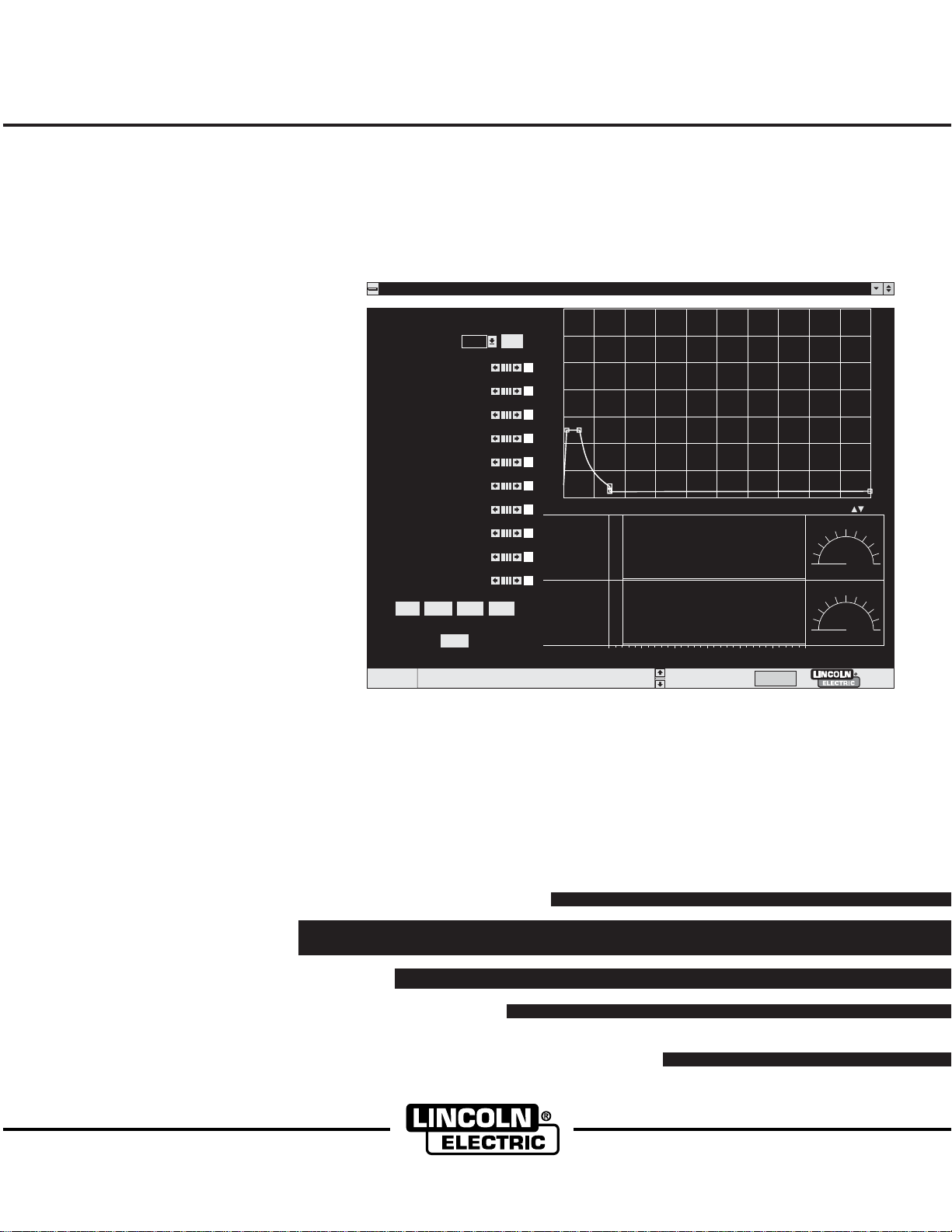
File Tools Print Help
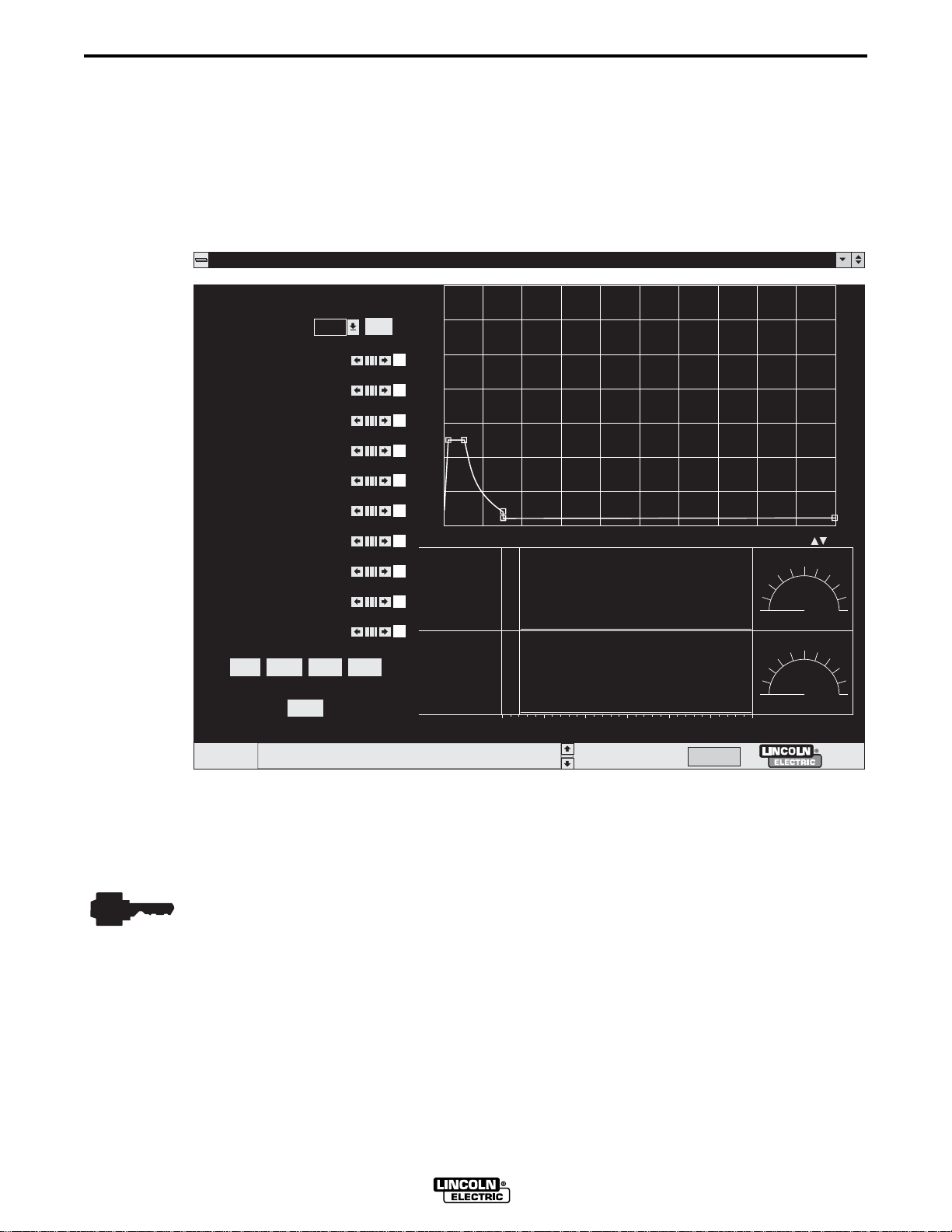
Pulse Waveform Editor
Adapt
About
AC.sco loaded
50
600
-20
250
1.2
3.0
.100
40
21
33.4
26.4
Short
Wire Feed Speed
Ramp Up Rate
Ramp Overshoot %
Peak Amps
Peak Time ms
Tailout Time
Tailout Speed
Stepoff Amps
Backgrd Amps
Backgrd Time
Frequency
Start
Status
Wave Designer Pro Off Line - pulse.swf
700
600
Edit
500
400
300
200
100
0
0 3 6 9 12 15 18 21 24 27 30
End
Off Line Stand by
Adaptive
May, 1999
World's Leader in Welding and Cutting Products Premier Manufacturer of Industrial Motors
Cleveland, Ohio 44117-1199 U.S.A. TEL: 216.481.8100 FAX: 216.486.1751 WEB SITE: www.lincolnelectric.com
SOFTWARE OPERATOR’S MANUAL
• Sales and Service through Subsidiaries and Distributors Worldwide •
Page 2

Page 3

i
License Information ..................................................................................................... ii
Introduction .................................................................................................... Section 1
1.1 Product Overview .......................................................................................... 1-1
1.2 User Responsibility ....................................................................................... 1-1
1.3 Computer System Requirements .................................................................. 1-1
1.4 Software Release Data ................................................................................. 1-2
1.5 Welding Equipment Requirements ................................................................ 1-2
Software Installation ...................................................................................... Section 2
2.1 File Storage Locations ................................................................................. 2-1
2.2 Software Installation Procedure .................................................................... 2-1
2.3 Equipment Interface Connections ................................................................. 2-2
2.4 Equipment/Software Startup ......................................................................... 2-4
2.5 Upgrade Firmware ........................................................................................ 2-4
Software Operation ........................................................................................ Section 3
3.1 Synergic Welding and Workpoints ................................................................ 3-1
3.2 Working in Wave Designer ............................................................................ 3-2
3.3 Wave Design Process ................................................................................. 3-11
3.4 Downloading Wave Shapes ........................................................................ 3-12
3.5 Autosave ..................................................................................................... 3-13
TABLE OF CONTENTS
Page
i
ArcScope ........................................................................................................ Section 4
4.1 Introduction ................................................................................................... 4-1
Troubleshooting ............................................................................................ Section 5
5.1 Overview ....................................................................................................... 5-1
5.2 Wave Designer Troubleshooting Procedure ................................................. 5-1
Pulse Wave Shaping Principles ............................................................... Appendix A
A.1 Appendix Overview ...................................................................................... A-1
A.2 GMAW Pulse Overview ................................................................................ A-2
A.3 Adaptive and Non-Adaptive Mode ................................................................ A-4
A.4 Pulse Wave Design Process ........................................................................ A-5
A.5 Primary Pulse Waveform Components ...................................................... A-14
A.6 Secondary Waveform Parameters ............................................................. A-16
A.7 Application Exercise ................................................................................... A-17
STT Wave Shaping Principles .................................................................. Appendix B
B.1 Appendix Overview ...................................................................................... B-1
B.2 STT Overview ............................................................................................... B-2
B.3 STT (Surface Tension Transfer) ................................................................... B-4
B.4 STT Wave Design Process .......................................................................... B-6
B.5 Primary STT Waveform Components ........................................................ B-12
B.6 Secondary STT Waveform Components .................................................... B-14
B.7 Application Exercise ................................................................................... B-15
WAVE DESIGNER
Page 4

ii ii
LICENSE INFORMATION
By clicking the acceptance button or installing the software, you are consenting to be bound by and are becoming
a party to this agreement. If you do not agree to all of the terms of this agreement, click the button that indicates
you do not accept the terms and do not install the software. (If applicable, you may return the product to the place
of purchase for a full refund.) If the copy of the software you received was accompanied by a printed or other
form of "hard-copy" end user license agreement whose terms vary from this agreement, then the hard-copy end
user license agreement governs your use of the software.
WAVE DESIGNER SOFTWARE LICENSE AGREEMENT
LICENSE:
Lincoln grants you the right to use the Wave Designer Software ("the Software"). You will not use, copy, modify, rent, sell or transfer this
Software, or any portion thereof, except as provided for in this Agreement. The Software includes and utilizes Java Runtime software owned
by Sun Microsystems, Inc. and this license is conditioned upon your agreement to the Sun Microsystems Binary Code License which is
attached and made a part of this license. There is no legal or commercial association between Lincoln and Sun Microsystems, Inc.
You may use the Software on a single computer and with any Lincoln arc welding equipment which you own or lease. If the software is
installed on a networked computer, only one (1) copy can be used at a time.
RESTRICTIONS
1) Use the Software on more than one computer or with non-Lincoln arc welding equipment.
2) Sub-license the Software.
3) Reverse engineer, de-compile, disassemble, modify, or extract archived files from the Software.
4) Copy the Software, except for backup purposes.
5) Sell, license, or patent welding applications, waveforms, or other know how developed with this Software.
NON-DISCLOSURE
You agree that the Software is and shall remain the property of Lincoln Electric, and that you will hold the Software in confidence for Lincoln.
You agree to make reasonable efforts to prevent unauthorized use of the Software, and to prevent disclosure to third parties.
ROYALTY-FREE
Provided you have paid the initial license fee, you will be under no obligation to pay Lincoln a royalty for the use of the Software when used as
permitted under this license.
WARRANTY
Lincoln warrants to the original purchaser that the Software will perform substantially as described in the Software documentation for a period
of 90 days from the date of purchase. Lincoln's liability under this warranty shall not exceed the amount you paid for the Software. No
warranty is made by Lincoln that the Software is free of errors or limitations. No warranty is made by Lincoln with respect to the Java Runtime
software.
THE ABOVE WARRANTIES ARE THE ONLY WARRANTIES OF ANY KIND EITHER EXPRESSED OR IMPLIED, INCLUDING
WARRANTIES OF MERCHANTABILITY OR FITNESS FOR A PARTICULAR PURPOSE. LINCOLN SHALL NOT BE LIABLE FOR ANY
LOSS OF PROFITS, LOSS OF USE, INTERRUPTION OF BUSINESS, NOR FOR INDIRECT, SPECIAL, INCIDENTAL OR
CONSEQUENTIAL DAMAGES OF ANY KIND WHICH RELATE TO USE OF THE SOFTWARE. SELECTION AND APPLICATION OF THE
SOFTWARE IS YOUR SOLE RESPONSIBILITY AND NO WARRANTY IS GIVEN WITH REGARD TO WELDING CHARACTERISTICS
DESIGNED USING THIS SOFTWARE OR THE SUITABILITY OF WELDS PRODUCED USING SUCH CHARACTERISTICS.
TRANSFER
You may transfer the Software, subject to this license, to another party if the receiving party also purchases from you the Invertec Power
Wave power source with which this Software is used. Prior to any such transfer, the transferee must agree to the terms of this license and
you must notify Lincoln, in writing, of the name and address of the party to whom the Software has been transferred. You must retain no
copies of the Software and accompanying documentation. Transfer of the license terminates your right to use the Software. This Software
may not be exported except as permitted by the export laws of the United States.
: You may not:
:
:
:
:
IMPROVEMENTS
From time-to-time, Lincoln may make improvements in the Software. You agree that there is no obligation on the part of Lincoln to provide
you with or notify you of any improvements. Such improvements may be purchased by you from Lincoln under the terms of a separate
License Agreement or Maintenance Agreement for that Software. Additional charges for installing and trouble-shooting may apply.
POST-TERMINATION OBLIGATIONS
If this Agreement is terminated, you must stop using the Software and, except in the case of transfer, destroy all copies. Your confidentiality
obligation shall survive termination and remain in effect for a period of five years following termination.
APPLICABLE LAW
This License Agreement shall be interpreted and construed in accordance with the laws of the State of Ohio, and any litigation brought under
this License Agreement shall be filed in the State or Federal Courts in the State of Ohio. The United Nations Convention for the International
Sales of Goods is expressly excluded. Any claim arising out of this License Agreement will first be submitted for resolution by arbitration.
TERM AND TERMINATION:
This Agreement shall remain in effect for so long as the Wave Designer Software is in use as permitted under this license. The license may
be terminated by you at any time by removing and returning to Lincoln all copies of the Software.
:
:
:
WAVE DESIGNER
Page 5

iii iii
JAVA RUNTIME ENVIRONMENT, VERSION 1.1.6, BINARY CODE LICENSE
This binary code license ("License") contains rights and restrictions associated with use of the accompanying Java Runtime Environment
software and documentation ("Software"). Read the License carefully before using the Software. By using the Software you agree to the
terms and conditions of this License.
1. License to Distribute. Licensee is granted a royalty-free right to reproduce and distribute the Software provided that Licensee: (i)
distributes the Software complete and unmodified (except for the specific files identified as optional in the Software README file), only as
part of, and for the sole purpose of running, Licensee's Java compatible applet or application ("Program") into which the Software is
incorporated; (ii) does not distribute additional software intended to replace any component(s) of the Software; (iii) agrees to incorporate
the most current version of the Software that was available 180 days prior to each production release of the Program; (iv) does not
remove or alter any proprietary legends or notices contained in the Software; (v) includes the provisions of Sections 2, 3, 5, 6, 8 and 9 in
Licensee's license agreement for the Program; and (vi) agrees to indemnify, hold harmless, and defend Sun and its licensors from and
against any claims or lawsuits, including attorneys' fees, that arise or result from the use or distribution of the Program.
2. Java Platform Interface. Licensee may not modify the Java Platform Interface ("JPI", identified as classes contained within the "java"
package or any subpackages of the "java" package), by creating additional classes within the JPI or otherwise causing the addition to or
modification of the classes in the JPI. In the event that Licensee creates any Java-related API and distributes such API to others for
applet or application development, Licensee must promptly publish broadly, an accurate specification for such API for free use by all
developers of Java-based software.
3. Restrictions. Software is confidential copyrighted information of Sun and title to all copies is retained by Sun and/or its licensors.
Licensee shall not decompile, disassemble, decrypt, extract, or otherwise reverse engineer Software. Software may not be leased,
assigned, or sublicensed, in whole or in part, except as specifically authorized in Section 1. Software is not designed or intended for use
in online control of aircraft, air traffic, aircraft navigation or aircraft communications; or in the design, construction, operation or
maintenance of any nuclear facility. Licensee warrants that it will not use or redistribute the Software for such purposes.
LICENSE INFORMATION
4. Trademarks and Logos. This License does not authorize Licensee to use any Sun name, trademark or logo. Licensee acknowledges
that Sun owns the Java trademark and all Java-related trademarks, logos and icons including the Coffee Cup and Duke ("Java Marks")
and agrees to: (i) comply with the Java Trademark Guidelines at http://java.sun.com/trademarks.html; (ii) not do anything harmful to or
inconsistent with Sun's rights in the Java Marks; and (iii) assist Sun in protecting those rights, including assigning to Sun any rights
acquired by Licensee in any Java Mark.
5. Disclaimer of Warranty. Software is provided "AS IS," without a warranty of any kind. ALL EXPRESS OR IMPLIED
REPRESENTATIONS AND WARRANTIES, INCLUDING ANY IMPLIED WARRANTY OF MERCHANTABILITY, FITNESS FOR A
PARTICULAR PURPOSE OR NON-INFRINGEMENT, ARE HEREBY EXCLUDED.
6. Limitation of Liability. SUN AND ITS LICENSORS SHALL NOT BE LIABLE FOR ANY DAMAGES SUFFERED BY LICENSEE OR ANY
THIRD PARTY AS A RESULT OF USING OR DISTRIBUTING SOFTWARE. IN NO EVENT WILL SUN OR ITS LICENSORS BE LIABLE
FOR ANY LOST REVENUE, PROFIT OR DATA, OR FOR DIRECT, INDIRECT, SPECIAL, CONSEQUENTIAL, INCIDENTAL OR
PUNITIVE DAMAGES, HOWEVER CAUSED AND REGARDLESS OF THE THEORY OF LIABILITY, ARISING OUT OF THE USE OF
OR INABILITY TO USE SOFTWARE, EVEN IF SUN HAS BEEN ADVISED OF THE POSSIBILITY OF SUCH DAMAGES.
7. Termination. This license shall automatically terminate 180 days after production release of the next version of the Software by Sun.
Licensee may terminate this License at any time by destroying all copies of Software. This License will terminate immediately without
notice from Sun if Licensee fails to comply with any provision of this License. Upon such termination, Licensee must destroy all copies of
Software.
8. Export Regulations. Software, including technical data, is subject to U.S. export control laws, including the U.S. Export Administration Act
and its associated regulations, and may be subject to export or import regulations in other countries. Licensee agrees to comply strictly
with all such regulations and acknowledges that it has the responsibility to obtain licenses to export, re-export, or import Software.
Software may not be downloaded, or otherwise exported or re-exported (i) into, or to a national or resident of, Cuba, Iraq, Iran, North
Korea, Libya, Sudan, Syria or any country to which the U.S. has embargoed goods; or (ii) to anyone on the U.S. Treasury Department's
list of Specially Designated Nations or the U.S. Commerce Department's Table of Denial Orders.
9. Restricted Rights. Use, duplication or disclosure by the United States government is subject to the restrictions as set forth in the Rights in
Technical Data and Computer Software Clauses in DFARS 252.227-7013© (1) (ii) and FAR 52.227-19© (2) as applicable.
10. Governing Law. Any action related to this License will be governed by California law and controlling U.S. federal law. No choice of law
rules of any jurisdiction will apply.
11. Severability. If any of the above provisions are held to be in violation of applicable law, void, or unenforceable in any jurisdiction, then
such provisions are herewith waived or amended to the extent necessary for the License to be otherwise enforceable in such jurisdiction.
However, if in Sun's opinion deletion or amendment of any provisions of the License by operation of this paragraph unreasonably
compromises the rights or increase the liabilities of Sun or its licensors, Sun reserves the right to terminate the License.
WAVE DESIGNER
Page 6

iv iv
LICENSE INFORMATION
WAVE DESIGNER
Page 7
Section 1 1-1
INTRODUCTION
KEY TOPICS
This symbol indicates the location of key concepts throughout this manual.
1.1 PRODUCT OVERVIEW
Wave Designer is a visual, interactive software application used to modify wave shapes for use
with programmable waveform-controlled welding machines such as the Power Wave 455. The
Wave Designer software package includes a standard set of waveforms commonly used in
commercial and industrial welding applications.
The Wave Designer software package is intended for use by a weld application engineer in
concert with a skilled welding technician properly trained in welding applications.
This Instruction Manual guides you through the installation and operation of Wave Designer to
modify selected standard wave shapes and produce pulsed waveforms tailored to your specific
welding applications. The resulting custom waveforms automatically adjust your welding machine
to produce consistent weld transfers throughout a range of wire feed speeds and arc lengths.
1.2 USER RESPONSIBILITY
Because design, fabrication, erection, and welding variables affect the results obtained in
applying this type of information, the serviceability of a product or structure is the
responsibility of the user. Variations such as plate chemistry, plate surface condition (oil,
scale), plate thickness, preheat, quench, joint fit-up, gas type, gas flow rate, and
equipment may produce results different than those expected. Some adjustments to
procedures may be necessary to compensate for unique individual conditions. When
possible, test all procedures, duplicating actual field conditions.
1.3 COMPUTER SYSTEM REQUIREMENTS
Wave Designer software is intended for use on Windows 95, Windows 98, or Windows NT 4.0.
It will not work with Windows NT 3.51, Windows 3.1, or Windows for Workgroups. The core of
this product is architecture-neutral (operating system independent). If you would like to have
Wave Designer on Solaris SPARC, Solaris x86, MAC OS, AIX, OS/2, or Linux, please notify us
at wavedesigner@lincolnelectric.com. With Java Internationalization, Wave Designer can
support numerous European and Asian languages. Send your foreign language request to
wavedesigner@lincolnelectric.com.
We recommend a Pentium processor, 32 MB of RAM, and 6 MB of hard drive disk space for
efficient program operation. When running, Wave Designer occupies at least 10 MB of RAM. If
your computer is low in memory, we suggest you close other programs that consume large
memory. If you have less than 32 MB RAM, you may be able to run Wave Designer with “virtual
memory”. Set up virtual memory with one of the following command sequences.
In Windows 95 or 98
Start | Settings | Control Panel | System | Performance
Virtual Memory | Let me specify my own virtual memory settings
Minimum 100 | OK | Are you sure you want to continue? Yes | Close
Do you want to restart your computer now? Yes
WAVE DESIGNER
Page 8

1-2 Section 1
In Windows NT 4.0 log on as Administrator
An RS-232 serial communication cable is required to use Wave Designer software with Power
Wave power sources. The Power Wave requires an RS-232 DB25 male connector. Most
computers feature an RS-232 DB-9 female connector as the COM serial port. (e.g. Radio Shack
cat no. 26-269 serial cable connects to this combination). Verify the set up on your computer as
it may differ.
We recommend using an 800 x 600 pixel or larger display monitor. A 640 x 480 display will not
show all the features of the Wave Designer Editor Screens.
INTRODUCTION
Start | Settings | Control Panel | System | Performance
Virtual Memory Change... | Initial Size (MB): 100 | Set | OK
Do you want to restart your computer now? Yes
1.4 SOFTWARE RELEASE DATA
Wave Designer is a product of The Lincoln Electric Company. Please send your comments,
questions, suggestions, and problem reports to wavedesigner@lincolnelectric.com.
Refer to the Wave Designer Welcome screen for the applicable release version of the Wave
Designer software package. Wave Designer is a JAVA (TM) application (applet) and it comes
bundled with Java Runtime Environment (JRE Version 1.1.6) from SUN Microsystems. You may
directly download JRE from http://java.sun.com/products/jdk/1.1/jre/index.html. More information
about JAVA technology can be found at the http://java.sun.com web site.
1.5 WELDING EQUIPMENT REQUIREMENTS
Wave Designer works only with the Power Wave 455 or similar Lincoln Electric Company
Programmable Waveform Controlled welding systems. The following welding equipment is
required to interface with Wave Designer and to produce sample welds.
• power source (Power Wave 455 or similar)
• wire feeder and associated gears and drive rolls (Power Feed 10 or similar)
• welding gun
• regulated supply of shielding gas
• continuous-feed electrode
• interconnecting hoses and cables
• sample weld materials
• oscilloscope (optional)
WAVE DESIGNER
Page 9

Section 2 2-1
SOFTWARE INSTALLATION
2.1 FILE STORAGE LOCATIONS
The Wave Designer default home directory is C:\Program Files\WaveDesigner.
Subdirectories included with Wave Designer are as follows:
• arcScope - user data file for ArcScope traces (Wave Designer Pro option only)
• bin - system executables and support files, do not tamper with these files
• export - user waveform data table in ASCII text and html format
• firmware - bundled system firmware for PW455 machines
• jre - bundled Java Runtime Environment 1.1.6 from Sun Microsystems
• map - waveform editor template map files, do not tamper with them
• pictures - image files for GMAW droplet transfer movies
• systemWeldFile - user custom waveform files
• weldModeFile - copies of the weld mode directory (weld files for the welding machine)
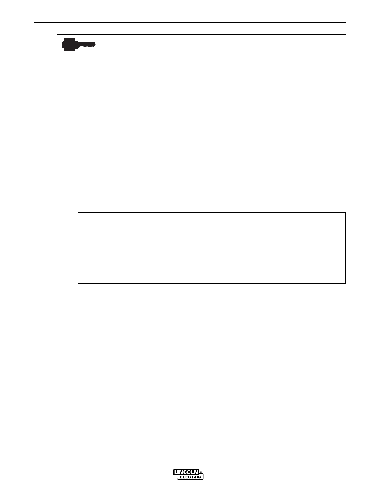
2.2 SOFTWARE INSTALLATION PROCEDURE
Standard installation (CD ROM version): Start | Run | Browse; Run D:\setup.exe
Install the Wave Designer program as you would any Windows application. Select the Wave
Designer program icon from your START window to start up the program. Refer to Table 2-1 for
alternate installation procedures. On startup, the Wave Designer screens in Figure 2-1 will be
displayed.
NOTE: If upgrading a previous software release, save your data files (waveforms, scope traces,
etc.) and uninstall the previous software release before installing the new version.
TABLE 2-1. ALTERNATE INSTALLATION PROCEDURES.
Application/
Operation Drive Command Sequence
Install Floppy Disk Version A Start | Run | Browse; Run setup.exe
Install Java Runtime All Create shortcut: <dir>\jrew.exe -ms12000000 -cp .\*.jar Pwgui
Executable Version Start Program: <dir>\Program Files\WaveDesigner\bin
Install Wave Designer Windows NT 4.0 Create Start Menu Shortcut; set icon for “All Users”
Icon
Start Wave Designer in a C Open C:\Program Files\WaveDesigner\bin
DOS Window Type: jre -ms12000000 -cp .\*.jar Pwgui
or:..\jre\bin\jre -ms12000000 -cp .\*.jar Pwgui
Start | Settings | Control Panel | Add/Remove Programs
Uninstall Program All Select Wave Designer in scroll window and click on
Add/Remove button. Use Windows Explorer or File Manager to
remove Wave Designer folder.
WAVE DESIGNER
Page 10
WAVE DESIGNER
2-2 Section 2
SOFTWARE INSTALLATION
FIGURE 2-1.
Copyright © 1998 The Lincoln Electric Company
Welcome to Wave Designer
Lincoln Electric Wave Designer Version 1.0
All Rights Reserved
STARTUP SCREEN.
Wave Designer
WARNING: This computer program is protected by copyright law
and international treaties. Unauthorized reproduction or
distribution of this program, or any part of it, may be prosecuted to
the maximum extent possible under the law.
United States Patent Pending
Comments? Write to wavedesigner@lincolnelectric.com
Initializing ... Please wait
2.3 EQUIPMENT INTERFACE CONNECTIONS
Wave Designer communicates welding parameter changes to the welding machine controller in
real time (on-the-fly). To enable communication with Wave Designer, reconfigure the welding
machine settings as follows:
1. Disconnect the electrical power to the welding machine.
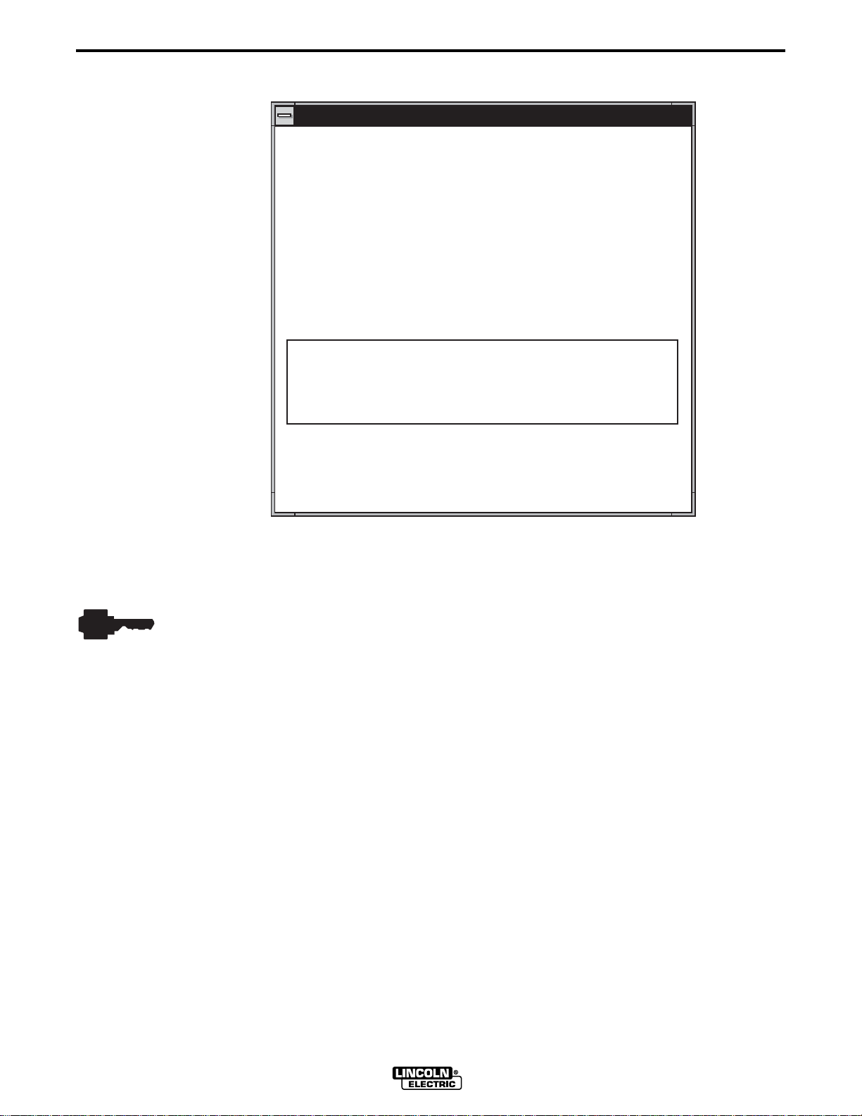
2. Remove the control box LED display panel, Figure 2-2. Be careful not to pull hard on the
panel wiring harness.
3. Locate the bottom DIP switch block (SW2) on the user interface control board. Move the last
DIP switch (position #8) up and reinstall the LED display panel.
4. Toggle the control box SELECT switch up and down until the Weld Mode indicator lights up.
Toggle the SET switch to get an OFF readout on the LED display.
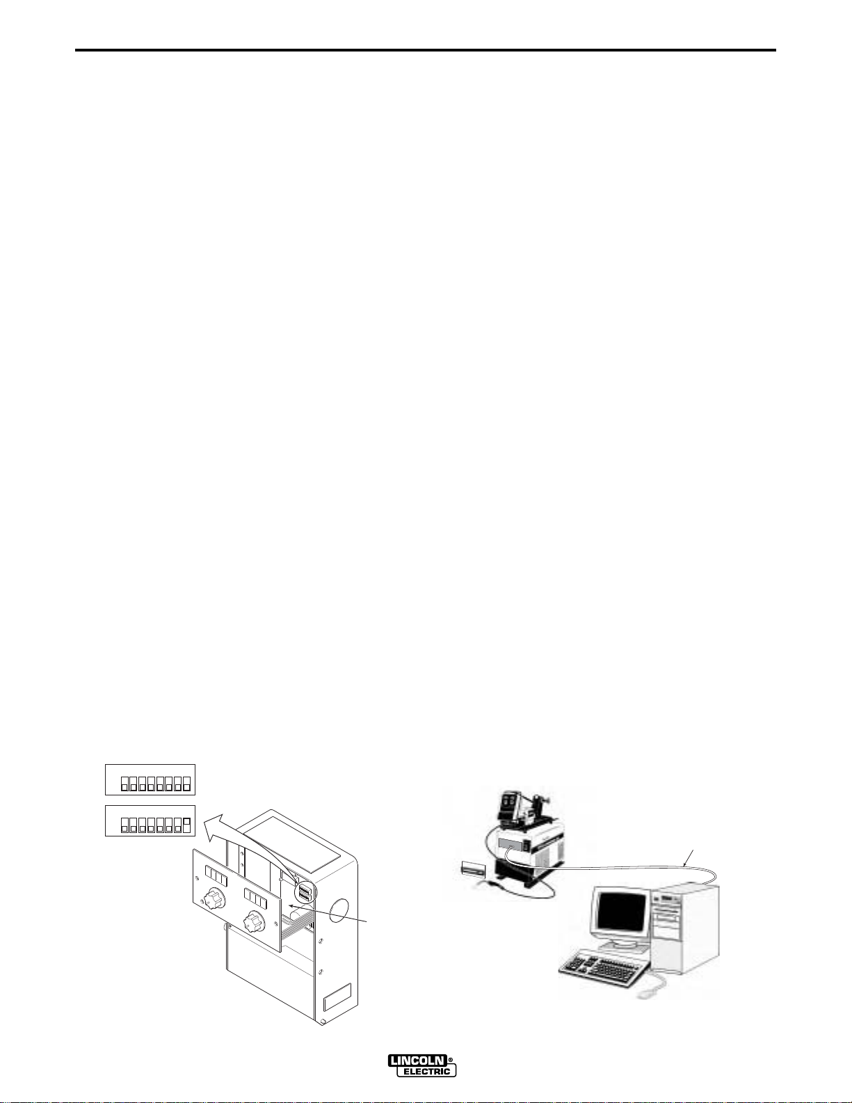
5. An RS-232 serial communication cable is required to use Wave Designer software with
Power Wave power sources. The Power Wave requires an RS-232 DB25 male connector.
Most computers feature an RS-232 DB-9 female connector as the COM serial port. (e.g.
Radio Shack cat no. 26-269 serial cable connects to this combination). Verify the set up on
your computer as it may differ.
27850002
6. Connect the RS-232 cable between the COM1 port of your computer and the mating
connector behind the front center panel of the power source, Figure 2-3.
WAVE DESIGNER
Page 11
Section 2 2-3
SOFTWARE INSTALLATION
PLEASE NOTE: Some IBM ThinkPads® by default have the serial port disabled and instead the port is used for infrared. The
following information describes the procedure to disable the infrared feature and enable the serial port. Follow the instructions
below to use COM1 to communicate with the PowerWave. More instructions at the end discuss how to use other ports, if
necessary.
The following information can also be found at the IBM website at
http://www.pc.ibm.com/qtechinfo/DSHY-3P5QW4.html
How to enable the external serial port on your ThinkPad
SYMPTOM:
The ThinkPad is not communicating with the PowerWave serial device.
CONFIGURATION:
Any ThinkPad trying to utilize the external serial port using any applicable operating systems.
RESOLUTION:
By default, currently available ThinkPads come with the external serial port disabled and Infrared enabled on COM 1. To use
the serial port on COM 1 you must either disable infrared or change infrared so that it uses alternate resources. If you are not
using infrared for printing or file sharing it is recommended that it be disabled.
To disable infrared and enable the serial port on COM 1 do the following:
1. Double-click your ThinkPad Features or ThinkPad Configuration icon located in the ThinkPad folder on your desktop.
2. Locate the Infrared button located on the left-hand side of this configuration screen and click it once.
(Note: If you hold your mouse pointer over any of the icons in this configuration screen the button will be identified at the
bottom in the status window.)
3. Change Infrared from "Enable" to "Disable" and click "OK".
4. Locate the serial port icon and click it once.
5. Select serial port "enable" and insure that the COM PORT setting is "COM 1" and click "OK".
6. Shut down and restart the computer.
More Information:
There are many different combinations of port settings that are possible. The following table indicates the standard settings for
the four available COM Ports:
COM 1 03F8 4 COM 2 02F8 3
COM 3 03E8 4 COM 4 02E8 3
Please note that COM 1 and 3 share IRQ 4 and COM 2 and 4 share IRQ 3. You can not configure multiple devices to the
same IRQ.
If not successful, try to use COM3. Follow the instructions above while substituting COM1 with COM3. Configure Wave
Designer by changing the properties of the Wave Designer icon (right click mouse when pointing to the icon), add "-port com3"
to the command line.
FIGURE 2-2. CONTROL BOARD DIP SWITCH SETTING.
SW1
SW2
ON
ON
112
5
3
66778
4
5
3
2
8
4
CONTROL
BOX
CONTROL
BOARD
27850003
FIGURE2-3. INTERFACE CONNECTION.
POWER
SOURCE
FRONT
PAN E L
RS232
CABLE
COMPUTER
SYSTEM
27850004
WAVE DESIGNER
Page 12
2-4 Section 2
SOFTWARE INSTALLATION
2.4 EQUIPMENT/SOFTWARE STARTUP
When the Wave Designer software installation is complete, Wave Designer is listed among the
programs you can start up from the Windows startup screen. Click on START, point to the
programs option, then click on the Wave Designer option. The Wave Designer Welcome
screen is displayed followed by the Pulse Waveform Editor screen. When the Pulse Waveform
Editor screen is displayed, the software is ready for use.
Wave Designer Pro Off Line - pulse.swf
File Tools Print Help
Pulse Waveform Editor
Wire Feed Speed
50
Edit
700
600
Ramp Up Rate
Ramp Overshoot %
Peak Amps
Peak Time ms
Tailout Time
Tailout Speed
Stepoff Amps
Backgrd Amps
Backgrd Time
Frequency
Adapt
Start
Status
AC.sco loaded
600
-20
250
1.2
3.0
.100
40
21
33.4
26.4
About
Short
End
500
400
300
200
100
0
0 3 6 9 12151821242730
27850001
Off Line Stand by
Adaptive
2.5 UPGRADE FIRMWARE
An ArcScope application is provided with Wave Designer Pro. In order to run the ArcScope
application, it may be necessary to upgrade the welding machine firmware. If the old firmware
does not support ArcScope, the ArcScope application will display garbled data rather than
waveforms. Wave Designer will automatically detect the firmware version and prompt you to
upgrade the firmware if required.
WAVE DESIGNER
Page 13

Section 3 3-1
SOFTWARE OPERATION
3.1 SYNERGIC WELDING AND WORKPOINTS
Prior to using Wave Designer it is important to have a good understanding of the concepts of
synergic welding and workpoints. Synergic welding is basically “one knob control” of a welding
process; all other variables of the process are adjusted by the power source based on the single
controlling variable. This single controlling variable is known as a workpoint. For example, in
synergic pulse welding (GMAW-P), the operator can adjust the wire feed speed (WFS). The
WFS is the workpoint. The synergic power source will then set all other GMAW-P variables
based on the WFS by “looking up” the other variables from a pre-programmed weld table. See
Figure 3-1.
Wave Designer is a program that lets you develop a customized weld procedure by letting you
program each variable for multiple workpoints into a weld “look up” table.
Power Wave power sources go even a step further than simply “looking up” pre-programmed
variables from a weld table. If a selected WFS is between two pre-programmed workpoints, the
Power Wave will interpolate values for each of the welding variables. The result is a precise and
continuous range of welding control.
Refering to Figure 3-1, lets examine how this interpolation works by looking at one welding
variable — background amps. The operator selects a wire feed speed of 175 in/min. This value is
between the pre-programmed workpoints of 150 and 200 in/min. The Power Wave interpolates
between the pre-programmed background amp values of 80 and 60 and adjusts the background
amps to 70.
FIGURE 3-1. WFS ENCODER AND WELD DATA TABLE.
WFS/AMPS
ENCODER
NOTE: WFS ENCODER SETTING
DETERMINES WELDING
PROCESS VARIABLES PER
RELATED WELD TABLE.
PRE-PROGRAMMED WELDING PROCESS VARIABLES INTERPOLATED
PARAMETER VALUE
100
90
WORK-
POINTS
(WFS)
80
100
150
200
250
PEAK CURRENT
280
280
280
280
280
PULSE WIDTH
1.2
1.2
1.2
1.2
1.2
BACKGROUND AMPS
FREQUENCY
20
40
60
80
100
50
60
80
90
100
80
70
60
50
40
30
BACKGROUND AMPS
20
10
0
INTERPOLATED
BACKGROUND AMPS
WIRE FEED SPEEDS
WFS = 175
1000 15050 200
27850005
WAVE DESIGNER
Page 14
WAVE DESIGNER
3-2 Section 3
SOFTWARE OPERATION
3.2 WORKING IN
3.2.1 WAVEFORM EDITOR WINDOW
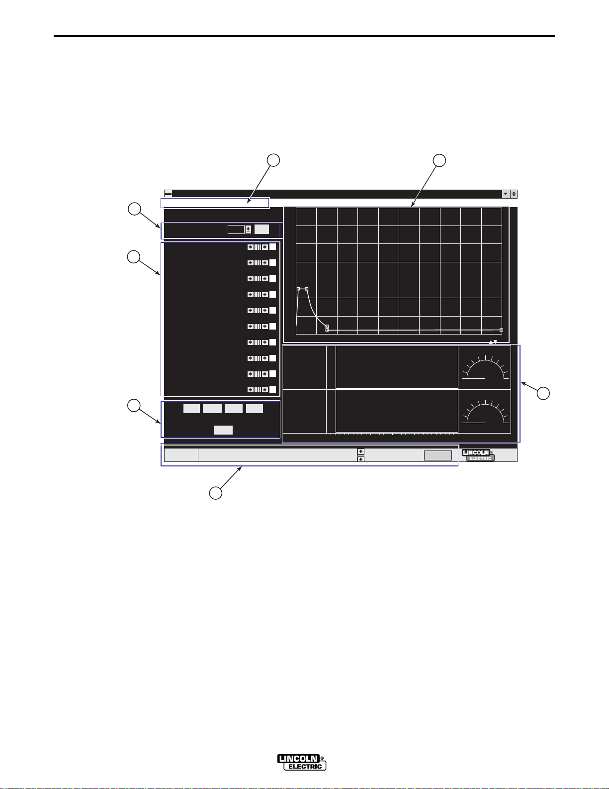
Refer to the Waveform Editor window in Figure 3-2 and the related usage instructions.
2
3
5
File Tools Print Help
Ramp Overshoot %
Status
FIGURE 3-2. WAVEFORM EDITOR WINDOW.
1
Wave Designer Pro Off Line - pulse.swf
Pulse Waveform Editor
Edit
600
-20
250
1.2
3.0
.100
40
21
33.4
26.4
Adapt
About
AC.sco loaded
50
Short End
Wire Feed Speed
Ramp Up Rate
Peak Amps
Peak Time ms
Tailout Time
Tailout Speed
Stepoff Amps
Backgrd Amps
Backgrd Time
Frequency
Start
4
700
600
500
400
300
200
100
0
0 3 6 9 12 15 18 21 24 27 30
Off Line Stand by
Adaptive
7
6
1. Tool Bar Tool bar menus access alternate windows, open and save files, etc. Detailed
instructions are provided in paragraph 3.2.2.
2. Workpoint Selector/Editor The workpoint selector includes a pulldown window for
selecting a workpoint and an edit window for changing the listing of workpoint values. For
the Pulse Waveform Editor, the workpoints are wire feed speeds. The workpoint parameter
(peak voltage, current, etc.) varies with the welding mode (pulse, STT, etc.). Refer to
paragraph 3.2.3 for more detail on selecting and editing workpoints.
3. Variable Parameters The listing of variable parameters display the active parameter
values for the selected WFS. The parameter values are changed (edited) with the related
arrows and slide bars or by moving parameter nodes in the waveform graphic editor. See
paragraph 3.2.4 for more details on editing variable parameters and the wave shape.
4. Graphic Editor The graphic editor displays the active wave shape. The wave shape
changes when the parameter values are changed. The displayed wave parameter nodes
(boxes) can be selected with your mouse to edit the variable parameters. Pressing the
<F1> key will also toggle from one selected node to another. See paragraph 3.2.4 for more
details on editing variable parameters and the wave shape.
WAVE DESIGNER
27850006
Page 15
Section 3
SOFTWARE OPERATION
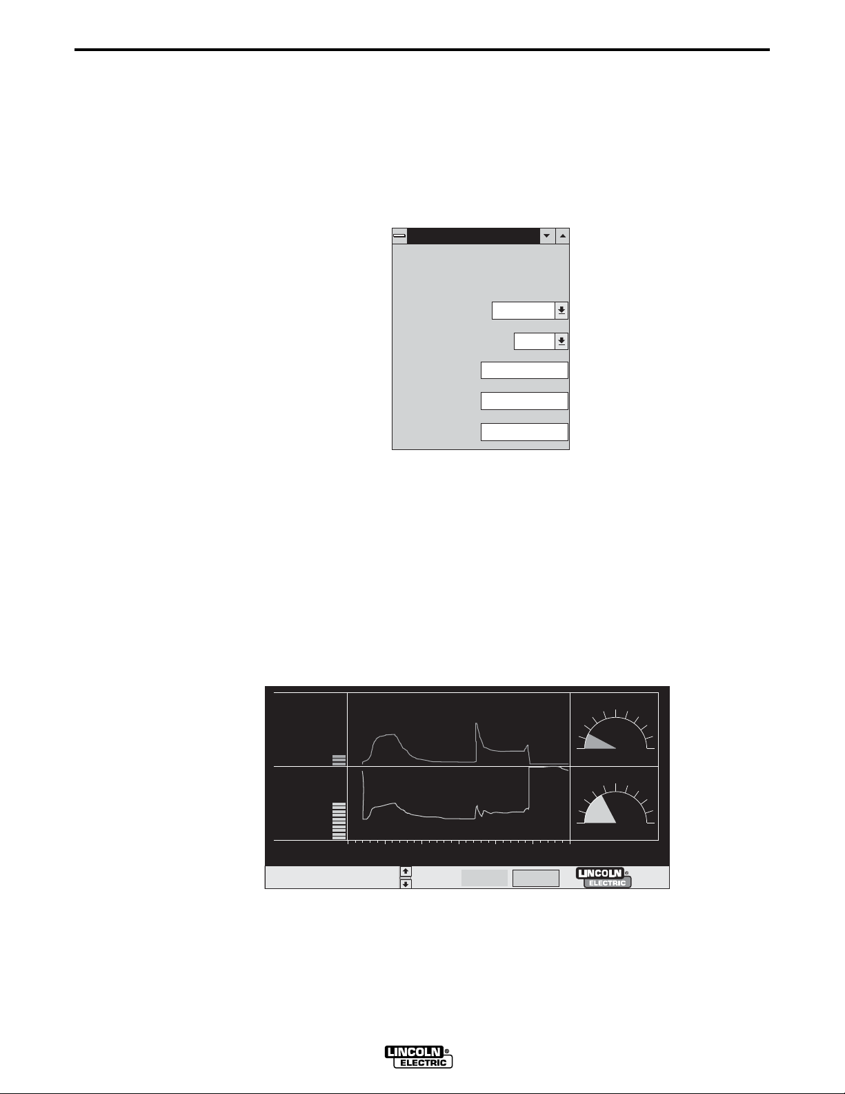
5. Optional Windows The optional window buttons open additional windows used during
wave shaping. Optional windows in the pulse Waveform Editor include Start, Adapt, Short,
End, and About. Details about the use of most optional windows is covered in the applicable
appendix (i.e. Appendix A for Pulse Wave Shaping). We use the About window shown in
Figure 3-3 to record descriptive weld application data for custom wave shape files. This
information is stored with the program in the computer and in the Power Wave.
FIGURE 3-3. THE “ABOUT” EDIT WINDOW.
About the Procedure
About the Procedure
Process Type
GMAW
3-3
Wire Size
Steel Pulse A
.035 Steel
super GAS
Other
6.3mm
27850007
Wire Type
Process Name
Procedure
Gas
6. Wave Designer Status Bar This status bar provides a scrolled listing of recent program
∂ ƒ
events, error conditions, etc. Use the arrow keys
to scroll through the listings. The status
bar includes three system status indicators: on line/off line, standby/welding, and
adaptive/non-adapt. The adaptive indicator is also a button that toggles between the
adaptive and non-adaptive mode.
7. Volts/Amps Display The Volts/Amps display, Figure 3-4, provides real time, oscilloscope
type displays of the voltage and amperage outputs from the connected power source.
Smaller display monitors (640 x 480 pixels or less) will not show the volts/amps display.
FIGURE 3-4. TYPICAL VOLTS/AMPS DISPLAY.
On Line
Welding
WAVE DESIGNER
Adaptive
27850008
Page 16

3-4 Section 3
SOFTWARE OPERATION
3.2.2 WAVEFORM EDITOR TOOL BAR
There are four menu selections available on the pulse waveform editor tool bar. The following
describes how to use the File, Tools, and Print menus. The Help menu is self explanatory.
3.2.2.1 FILE MENU
The File menu provides options for accessing
and managing waveform data files. The File
menu options include the following:
Open Waveform Ctrl+O
Use the Open Waveform option to open a
Wave Designer waveform or an in-house
custom waveform you created and saved
earlier.
Save Waveform As ...
Use the Save Waveform As ... option to save
an open waveform under a different filename.
Save Waveform Ctrl+S
The Save Waveform option saves all recent
changes to an open waveform file.
Open Scope Trace (Wave Designer Pro option only)
Use the Open Scope Trace option to open a graphical display of oscilloscope type waveforms
(volts, ohms, amps, etc.) for any stored waveform (.swf) file.
File
Tools Print Help
Open Waveform Ctrl+O
Save Waveform As ...
Save Waveform
Ctrl+S
Open Scope Trace
Save Scope As ...
Save Scope
Export to Text File
Export to HTML Web Pages
Import Text File
Quit
Ctrl+Q
27850009
Save Scope As ... (Wave Designer Pro option only)
Use this option to save an open Scope Trace file under a different filename.
Save Scope (Wave Designer Pro option only)
The Save Scope option saves changes to the parameters in a .sco file caused by recent changes
to an open waveform file. Failure to actively open and save the Scope Trace file may result in an
inaccurate parameter record for a waveform undergoing design changes.
Export to Text File
Use the Export to Text File option to save a tabular record of the waveform variables data at
each of its design (Wire Feed Speed) workpoints.
Export to HTML Web Pages
Use the Export to Web Pages option to copy a custom waveform to a web page for transmission
of the waveform to Lincoln Electric for review.
Quit Ctrl+Q
Use the Quit option to exit the Wave Designer program.
WAVE DESIGNER
Page 17
Section 3 3-5
SOFTWARE OPERATION
3.2.2.2 TOOLS MENU
The Tools menu includes waveform display
options and other tools required to operate
Wave Designer. The Tools menu options
include the following:
Pulse Editor Ctrl+P
Display the Pulse Waveform Editor screen.
STT Editor Ctrl+E
Display the STT Waveform Editor screen.
Simplify Editor
Tools Print
Help
Pulse Editor Ctrl+P
STT Editor
Simplify Editor
ArcScope
Flash Custom Waveform
Browse Mode Directory
Upgrade Firmware
Go Offline
Display the primary wave shaping parameters
only. (See page A-1.)
ArcScope Ctrl+A
(Wave Designer Pro option only)
Display the Scope Trace screen for the currently displayed waveform.
Flash Custom Waveform Ctrl+F
Transmit selected waveforms to the welding
machine. This option requires that the
equipment interconnections are made and
that the welding machine is on-line
(communicating).
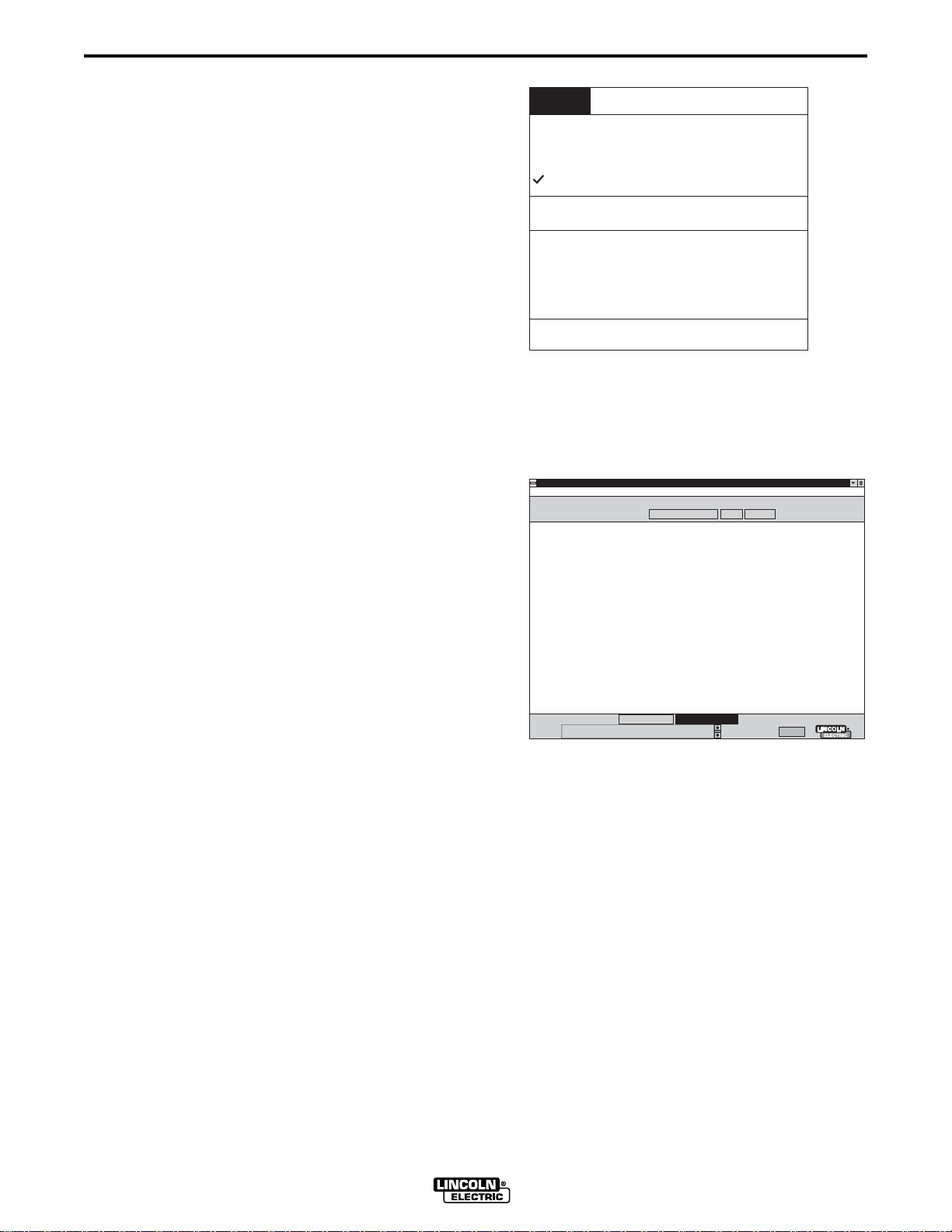
Browse Mode Directory Ctrl+B
Display the Weld Mode Directory screen. The
Weld Mode Directory lists the waveforms that
are presently downloaded into the welding
machine controller memory. You can
download up to ten custom waveforms to the
weld mode directory, memory slots (Modes)
File Tools Print Help
Mode 12: NST3510C.SWG: Steel Pulse, .035 Steel, Argon CO2 Blends
Mode 20: N45ST00C.SWG: Mig 3, .045 Steel, CO2
Mode 21: N45ST10C.SWG: Mig 3, .045 Steel, Argon CO2 Blends
Mode 22: NST4510C.SWG: Steel Pulse, .045 Steel, Argon CO2 Blends
Mode 24: N52ST00C.SWG: Mig 3, .052 Steel, CO2
Mode 25: N52ST10C.SWG: Mig 3, .052 Steel, Argon CO2 Blends
Mode 26: NST5210C.SWG: Steel Pulse, .052 Steel, Argon CO2 Blends
Mode 31: N35SS02.SWG: Mig 3, .035 Stainless, Argon Oxy Blends
Mode 32: NSS3502.SWG: Stainless Pulse2, .035 Stainless, Argon Oxy Blends
Mode 41: N45SS02.SWG: Mig 3, .045 Stainless, Argon Oxy Blends
Mode 42: NSS4502.SWG: Stainless Pulse2, .045 Stainless, Argon Oxy Blends
Mode 71: N48AL43.SWG: MIG 1, 3/64 4043, 100% Argon
Mode 72: NAL4843.SWG: Aluminum Pulse, 3/64 4043, 100% ARGON
Mode 73: N62AL43.SWGL MIG 1, 1/16 4043, 100% Argon
Mode 74: NAL6243.SWG: Aluminum Pulse, 1/16 4043, 100% Argon
Mode 75: N48AL56.SWG: MIG 1, 3/64 5356, 100% Argon
Mode 76: NAL4856.SWG: Aluminum Pulse, 3/64 5356, 100% Argon
Mode 77: N62AL56.SWG: MIG 1, 1/16 5356, 100% Argon
Mode 78: NAL6256.SWG: Aluminum Pulse, 1/16 5356, 100% Argon
Mode 81: N45MC10C.SWG: FCAW_GS, .045 MC-710, Argon CO2 Blends
Mode 82: NMC4510C.SWG: Pulse Metal Core, .045 MC-710, Argon CO2 Blends
Mode 90: N45OS00C.SWG: FCAW_GS, .045 FCAW-GS, 100% CO2
Mode 91: N45OS20C.SWG: FCAW_GS, .045 FCAW-GS, Argon CO2 Blends
Mode 200: mode200.SWG: CC TEST USING WP, 25A-600A,
Mode 201: MODE201.SWG: CV TEST USING WP, 10V-35V,
Mode 202: MODE202.SWG: CC TEST, NO WP, FIXED AT 10A,
Mode 203: MODE203.SWG: CC TEST, NO WP, FIXED AT 355A,
Mode 204: MODE204.SWG: CC TEST, NO WP, FIXED AT 455A,
Mode 205: MODE205.SWG: CC TEST, NO WP, FIXED AT 550A,
Mode 206: MODE206.SWG: CV TEST, NO WP, FIXED AT 30V,
weldfile uploaded
Status
Wave Designer Pro Off Line - pulse.swf
Search Weld Mode Directory
Search for:
Upload from Machine
155 through 164.
Ctrl+E
Ctrl+A
Ctrl+F
Ctrl+B
Search Browse All
0% done
Off Line
Stand by
27850010
Adaptive
27850011
Upgrade Firmware
Use this option when installing new firmware on your welding machine. The new firmware is
required to run this Wave Designer software release. When later software releases are issued,
they may or may not include firmware upgrades. If firmware upgrades are included, you will use
the Upgrade Firmware option to install the upgrades.
Go Offline
Use the Go Offline option to temporarily interrupt and re-establish communications between the
welding machine / wire feeder and Wave Designer.
WAVE DESIGNER
Page 18
3-6 Section 3
SOFTWARE OPERATION
3.2.2.3 PRINT MENU
Print menu options enable you to print out a waveform display, ArcScope screen, or tabular
waveform data listing as shown below. The Print menu options include the following:
Wave Designer Pro Waveform Editor
Printed on Thu Jul 09 07:24:50 EDT 1998
..\systemWeldFile\pulse.swf
For Wire Feed Speed 150 inch / min
700
600
500
400
300
200
100
0
0 3 6 9 1215 182124 2730
Print
Ramp Up Rate
Tailout Time
Peak Amps
Stepoff Amps
Backgrd Amps
Peak Time ms
Backgrd Time
Frequency
Tailout Speed
Ramp Overshoot %
Peak Voltage
Adaptive Type
Inductance
Short Detect Volt
Pinch Current Rise Rate
Arc Restablish Volt
End Amp
End Time
Open Circuit Volt
Strike Peak Time
Strike Peak Amps
Start Volt
Start Time
Start Amps
Help
600
1.5
280
25
20
1.4
8.7
83.3
.100
-7
30.0
Fresa
2.625
5.0
55
15.0
550
2.5
48.0
2.5
550
28.0
87.5
172
Waveform Ctrl+W
ArcScope Capture
Ctrl+C
Variable Table Ctrl+T
Wave Designer Pro Data Table Created on Thu Jul 09 07:26:41 EDT 1998
..\systemWeldFile\pulse.swf
Weld Process: SMAW
Wire Type: Other
Wire Size: 6.3mm
Process Name: Steel Pulse A
Procedure: .035 Steel
Gas: super GAS
WireFeed inch / min 50 80 110 150 205 300 400 600 700 850 1000 1200
Ramp Up Rate
Tailout Time
Peak Amps
Stepoff Amps
Backgrd Amps
Peak Time ms
Backgrd Time
Frequency
Tailout Speed
Ramp Overshoot %
Peak Voltage
Adaptive Type
Inductance
Short Detect Volt
Pinch Current Rise Rate
Arc Restablish Volt
End Amp
End Time
Open Circuit Volt
Strike Peak Time
Strike Peak Amps
Start Volt
Start Time
Start Amps
600
3.0
250
40
21
1.2
33.4
26.4
.100
-20
24.00
Mora
2.999
5.0
55
15.0
550
2.5
48.0
1.5
550
28.0
50.0
50
600
3.0
250
45
28
1.4
20.2
40.2
.100
-17
26.0
Naranja
2.251
5.0
55
15.0
550
2.5
48.0
2.5
550
28.0
50.0
83
600
3.0
260
25
20
1.5
9.1
71.9
.100
-23
27.00
Manzana
2.251
5.0
55
15.0
550
2.5
48.0
2.5
550
28.0
75.0
145
600
1.5
280
25
20
1.4
8.7
83.3
.100
-7
30.0
Fresa
2.625
5.0
55
15.0
550
2.5
48.0
2.5
550
28.0
87.5
172
600
1.5
300
30
25
1.4
4.7
125.0
.250
-12
31.0
Sandia
2.999
5.0
55
15.0
550
2.5
48.0
2.5
550
28.0
100.0
200
600
1.5
350
70
45
.8
3.8
151.5
.250
-1
34.00
Mora
1.499
5.0
55
15.0
550
2.5
48.0
2.5
550
28.0
75.0
250
800
1.5
420
60
60
.8
3.0
175.4
.250
-10
39.50
Mora
-0.00
5.0
55
15.0
550
2.5
48.0
2.5
550
28.0
50.0
325
800
1.0
470
90
90
.8
2.3
222.2
.250
-13
41.0
Mora
-0.00
5.0
55
15.0
550
2.5
48.0
2.5
550
28.0
50.0
350
800
1.0
500
150
150
.8
2.2
227.3
.250
-6
41.50
Mora
-0.00
5.0
55
15.0
550
2.5
48.0
2.5
550
28.0
50.0
425
800
1.0
535
190
190
.8
2.0
238.1
.250
-5
43.0
Mora
-0.00
5.0
55
15.0
550
2.5
48.0
2.5
550
28.0
50.0
438
800
1.0
520
230
230
.9
1.7
256.4
.250
-10
43.5
Mora
-0.00
5.0
55
15.0
550
2.5
48.0
2.5
550
28.0
50.0
450
800
1.0
540
270
270
.9
1.7
256.4
.250
-6
44.00
Mora
-0.00
5.0
55
15.0
550
2.5
48.0
2.5
550
28.0
50.0
475
Wave Designer ArcScope
Printed on Thu Jul 09 07:25:58 EDT 1998
50
---
Volt
---
Amp
.00
dV/dt
1.0
Ohm
7840
Watt
0 Amp
0.0 Volt
0.0 KW
0.0 KJ
0.0 Sec
Measured: N/A
25
0
700
350
0
100
0
-100
1
.5
0
10000
5000
0
0 10 20 30 40
WAVE DESIGNER
27850012
Page 19
Section 3 3-7
SOFTWARE OPERATION
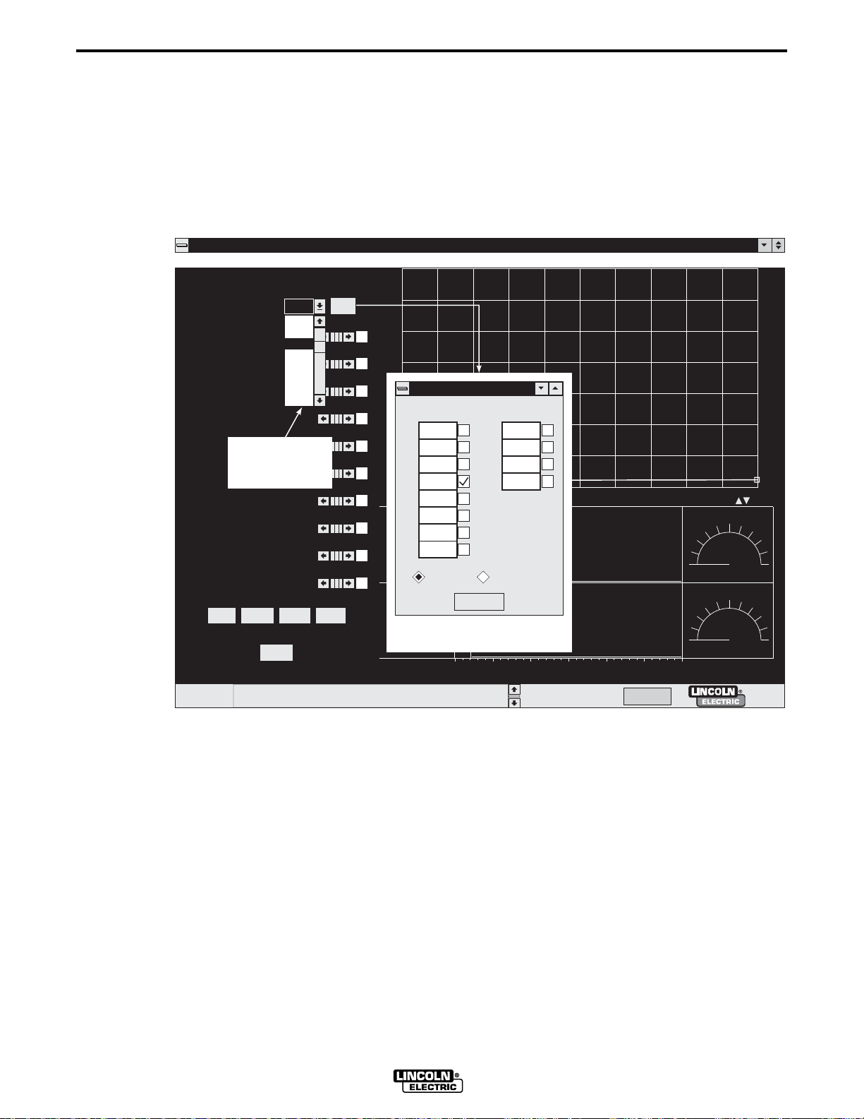
3.2.3 EDITING AND SELECTING WORKPOINTS
For each custom welding application, unique wave shapes are developed for specific workpoints
within the range of workpoints defined for the application. In Wave Designer the range of
workpoints and the specific workpoint values are defined in a Workpoint Editor window. After the
workpoints are defined, we use a workpoint pulldown menu to select a specific workpoint for
wave shaping. The following describes how workpoints are defined (edited) and selected for a
Pulse (GMAW) mode welding application.
Wave Designer Pro Off Line - pulse.swf
File Tools Print Help
Pulse Waveform Editor
Adapt
600
-20
250
1.2
3.0
.100
40
21
33.4
26.4
About
50
80
110
150
205
300
400
600
700
Short
Wire Feed Speed
Ramp Up Rate
Ramp Overshoot %
Peak Amps
Peak Time ms
Tailout Time
WORKPOINT
PULLDOWN
Tailout Speed
MENU
Stepoff Amps
Backgrd Amps
Backgrd Time
Frequency
Start
Edit
End
700
600
500
400
300
WorkPoint Editor
WorkPoint Editor
200
80 700
0
80 700
1
100
110 700
2
150 700
3
0
0 3 6 9 12151821242730
205
4
300
5
400
6
600
7
inch / min meter / min
WORKPOINT
EDITOR WINDOW
8
9
10
11
700
350
0
60
Go Figure
30
0
0 102030405060
0
0
350
0
30
0
700
60
Status
AC.sco loaded
WAVE DESIGNER
Off Line Stand by
Adaptive
27850013
Page 20
3-8 Section 3
SOFTWARE OPERATION
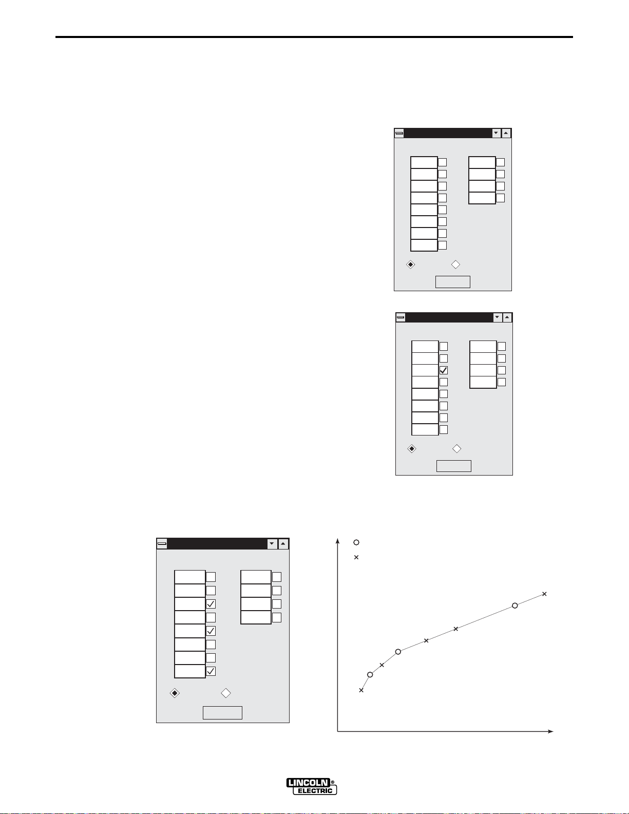
3.2.3.1 EDITING WORKPOINTS
Clicking on the Edit button in the waveform Editor window opens a Workpoint Editor window. The
Workpoint Editor window displays a listing of workpoints for the selected standard waveform. Use
the Workpoint Editor window according to the following descriptions and guidelines:
• Each workpoint value must be equal to or greater
than the preceding workpoint value.
• The workpoints range is from the lowest defined
workpoint to the highest.
• Successive workpoint boxes can share the same
value. Equivalent workpoints will share the same
wave shape. Wave Designer selects the last
workpoint of equal value as the controlling
workpoint.
• You can click on the related check box to lock (fix)
the wave shape variables for a developed
workpoint.
• You can click on the Go Figure button to
extrapolate/interpolate fixed workpoint parameter
values for all non-checked workpoints.
• When only one workpoint is fixed (checked), Go
Figure copies the workpoint (sets the wave shape
parameters for all other defined workpoints equal
to those of the fixed workpoint). This function
should be used just after the wave shape for the
first workpoint is fully developed.
• When two or more workpoints are developed and
fixed, selecting Go Figure performs a linear
interpolation of the wave shape parameters
between checked workpoints and extrapolation to
unchecked workpoints outside the checked ones.
WorkPoint Editor
WorkPoint Editor
80 700
0
80 700
1
110 700
2
150 700
3
205
4
300
5
400
6
600
7
inch / min meter / min
WorkPoint Editor
8
9
10
11
Go Figure
WorkPoint Editor
80 700
0
80 700
1
110 700
2
150 700
3
205
4
300
5
400
6
600
7
inch / min meter / min
10
11
Go Figure
28750014
8
9
28750015
WorkPoint Editor
WorkPoint Editor
80 700
0
80 700
1
110 700
2
150 700
3
205
4
300
5
400
6
600
7
inch / min meter / min
8
9
10
11
Go Figure
WP2
WORKPOINT VARIABLE
WP0, 1
WAVE DESIGNER
FIXED VALUE
INTERPOLATED/
EXTRAPOLATED VALUE
WP4
WP3
WP6
WP5
WORKPOINT
WP8, 9, 10, 11
WP7
28750016
Page 21
Section 3 3-9
SOFTWARE OPERATION
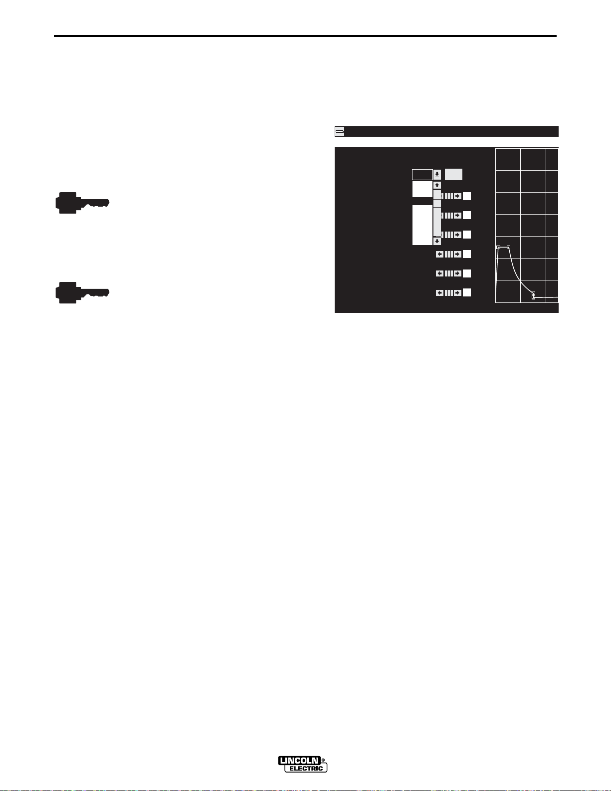
3.2.3.2 SELECTING WORKPOINTS
Clicking on the workpoint display box in the waveform Editor window opens a Workpoint
pulldown menu. The pulldown menu displays the listing of workpoints defined for the active
waveform. Use the pulldown menu according to the following descriptions and guidelines:
• Click on any one of the listed workpoints
to access the related waveform.
• The related welding machine control
must be set to the selected parameter
value. If the welding machine setting is
not equal to the selected workpoint
value, changes to the wave shape will
be applied to the workpoint value
nearest the welding machine setting.
• The welding machine Trim encoder must
be set to 1.00; the Arc control to “OFF”,
and the Mode control to “OFF”. Failure
to verify these welding machine
settings will defeat all wave shaping
efforts.
File Tools Print Help
Pulse Waveform Editor
600
-7
280
1.4
3.0
.100
50
80
110
150
205
300
400
600
700
Wire Feed Speed
Ramp Up Rate
Ramp Overshoot %
Peak Amps
Peak Time ms
Tailout Time
Tailout Speed
Wave Designer Pro Off
700
Edit
600
500
400
300
200
100
0
024
27850017
WAVE DESIGNER
Page 22
3-10 Section 3
SOFTWARE OPERATION
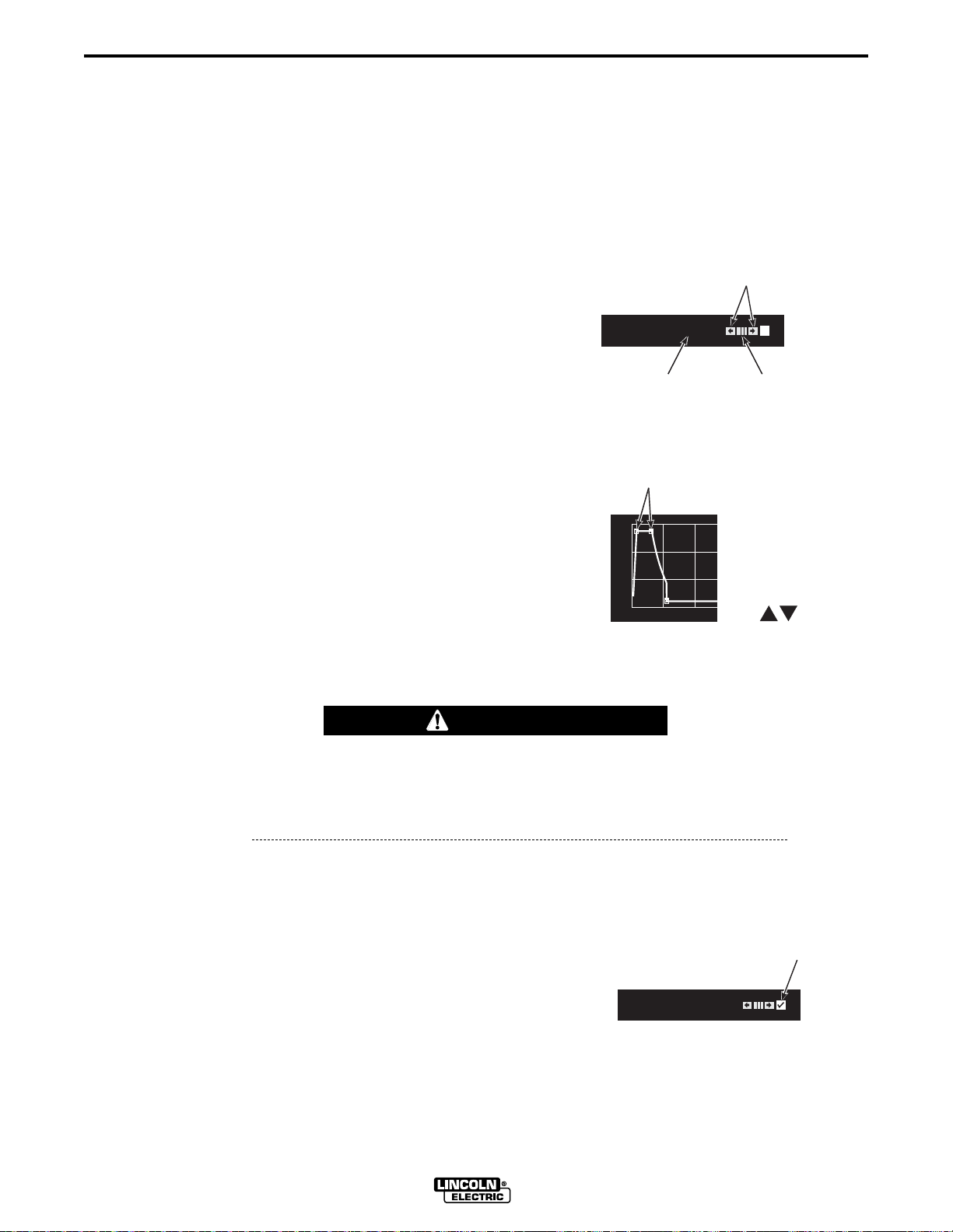
3.2.4 EDITING VARIABLE PARAMETERS
The following is a summary of the different methods available for changing (editing) parameter
values on the Waveform Editor screen and other display screens accessible through Wave
Designer. Read the following information carefully before making parameter changes on the
Waveform Editor screen.
• The variable editor and wave shape graphic functions are interrelated.
• Click once on an edit parameter arrow to increase or
decrease the parameter value by one unit; click and
hold the arrow to ramp the value up or down.
• Click on and drag the parameter display scroll bar to
scroll through the value range.
• Select (highlight) the parameter value. Select and
∂ ƒ
use the up/down keys
to change the value. Hold
down the Ctrl key while using the up/down keys to
change the value 10 times faster. You may directly
type in the desired value.
• Click on a node (hot spot) on the waveform graphic
and use the parameter arrows or drag the node with
your mouse as needed to achieve the desired
parameter value readout. Use the keyboard arrow
∂ ƒ ß ©
keys
to move the hot spot. Press Ctrl and an
arrow key to move the hot spot 10 times faster. Use
the F1 key to jump to the next hot spot.
Peak Amps
250
PARAMETER
VALUE
NODES
300
200
100
0
036
EDIT PARAMETER
ARROWS
SCROLL
BAR
27850018
CONTRACT
GRAPHIC
EXPAND
GRAPHIC
27850019
CAUTION
Uncontrolled drag with the mouse can result in large changes to the welding
machine output. Large changes can result in unexpected and undesired results.
We recommend using the edit arrows or keyboard entry to change parameter
values on-line.
• The expand and contract graphic arrows change the time scale on the X-axis to expand or
contract the wave shape.
To select a Waveform Editor parameter for edit, click on
the parameter check boxes as needed to erase the
checkmarks for all other parameters.
If a parameter has a visible checkmark, the related
Peak Amps
250
parameter value will remain fixed; you cannot change it.
When a parameter is known to be set properly, you may
wish to leave it fixed while adjusting other parameters. However, the variables are interrelated;
changing parameters while one or more is fixed may unpredictably effect other variables.
WAVE DESIGNER
PARAMETER
CHECK BOX
27850020
Page 23
Section 3 3-11
SOFTWARE OPERATION
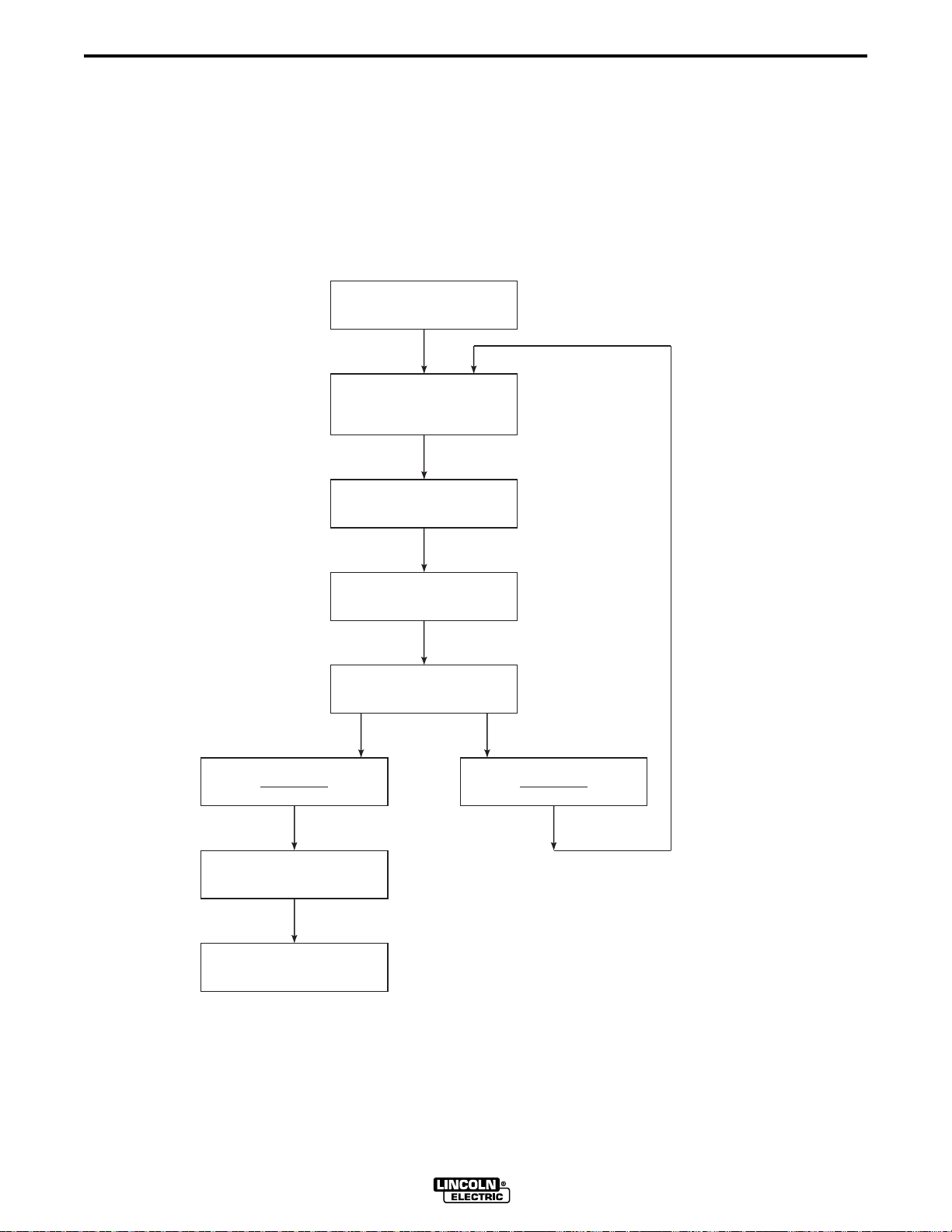
3.3 WAVE DESIGN PROCESS
The wave design process is a series of operations that allows you to quickly modify a standard
waveform to fit your specific welding application. The following process flowchart applies to a
pulse waveform, but is similar to the process used to modify STT and other waveforms.
Examples of each process step can be found in the listed reference paragraphs.
PROCESS FLOW: REFERENCE
PARAGRAPH:
Select a Waveform
from Memory
Mode = OFF
Select Workpoint
Set Powerwave WFS
Set Trim = 1.00
Set Arc Control = OFF
Set NO-ADAPT
(SEE APPENDIX A)
A-4.1
A-4.2 Step 1
GO FIGURE
Save File to Disk
Adjust Pulse
Variables at
Fixed Stickout
Set ADAPT
Adjust Peak Volts
and
Adaptive Type
Adjust Optional
Variables
(if needed)
GO FIGURE
A-4.2 Step 2
A-4.2 Steps 3 & 4
A-4.2 Steps 5, 6, & 7
Save File to Disk; Develop Next Workpoint
A-4.2 Step 8
Download File to Welding
Machine Memory
Section 3, paragraph 3.4
27850021
WAVE DESIGNER
Page 24

3-12 Section 3
SOFTWARE OPERATION
3.4 DOWNLOADING WAVE SHAPES
The Power Wave stores wave shapes in the welding machine controller memory. The memory
structure does not allow an upload or download of individual wave shapes. When downloading
wave shapes to the welding machine, the entire welding machine memory must be overwritten.
Each wave shape must be re-selected for download to the flash memory. Two methods are
available to access desired weld files; use the “Upload From Machine” option in the Weld Mode
Directory window or (if the weld files are all factory default files) select the “Bundled Factory
Default” option from the Flash Custom Waveform window. Any custom wave shapes not
specifically selected for download will not be re-written to the welding machine’s flash memory.
When downloading files to a new Power Wave welding machine, be aware that the bundled
factory default files in the Wave Designer software may be out of date, but needed for use with
older welding machines. Save the old factory default files in a new, “old weld files” directory and
access the latest factory default files from the Lincoln Electric web site for use on the newer
Power Wave machine(s).
Weld files can be corrupted during upload from a welding machine. If a weld file is corrupted, you
will not be able to upload the machine’s weld mode directory.
You can download up to ten custom waveforms to the weld mode directory. The assigned
memory slots are Modes 155 through 164. When all ten slots are in use, the only way to install
another custom waveform is to overwrite one of the ten allocated memory slots. Use the
following procedure to download acceptable wave shapes to the allocated welding machine
memory.
1. Select the Flash Custom Waveform option from the Tools menu to display the Flashing
PowerWave Custom Weld Files screen.
File Tools Print Help
This procedure re-programs the custom weld files i n permanent memory (flash) storage
Mode 155
Mode 156
Mode 157
Mode 158
Mode 159
Mode 160
Mode 161
Mode 162
Mode 163
Mode 164
Wave Designer Pro Off Line - pulse.swf
Flashing PowerWave Custom Weld Files
It allows welding with custom weld files without Wave Designer in production
This will erase existing custom weld files. It will take a few minutes to complete.
Choose...
Choose...
Choose...
Choose...
Choose...
Choose...
Choose...
Choose...
Choose...
Choose...
Desc
Desc
Desc
Desc
Desc
Desc
Desc
Desc
Desc
Desc
Size
Size
Size
Size
Size
Size
Size
Size
Size
Size
Status
AC.sco loaded
Custom Weld File Storage Space Left:
Merge your files int o: Bundled factory default
Bundled factory default
Save t
Last uploaded files
Newly uploaded files
Off Line Stand by
WAVE DESIGNER
0% done
No Adapt
27850022
Page 25

Section 3 3-13
2. Select a blank Mode or a defined Mode for overwrite by clicking on a box to the left of the
Modes listing. When the Mode is selected, a checkmark appears in the Mode box.
3. Enter the file name of the desired waveform in the box to the right of the selected Mode
number. Click on the Choose button to find the exact name of the weld file(s) you wish to
download. Click on the weld file name to select the file for download.
4. Use steps 2 and 3 to assign up to ten new file names to the weld Modes list. If a good weld
file was already stored in the welding machine’s memory, you must re-enter the name of the
stored weld file to download it to the welding machine.
5. Click on one of the three “Merge your files into:” options. Select the desired option per the
following descriptions.
a. Bundled factory default — Merges selected files with factory default files for download.
b. Last uploaded files — Merges selected files with weld mode directory last uploaded
from a welding machine. Overwrites modes 155 through 164 if like mode I.D.
number(s) are assigned to selected file(s).
c. Newly uploaded files — Merges selected files with directory of connected welding
machine. Overwrites modes 155 through 164 if like I.D. number(s) are assigned to
selected file(s).
SOFTWARE OPERATION
6. Click on the button at the bottom of the screen to download the selected
files to the welding machine’s Weld Mode Directory.
3.5 AUTOSAVE
When working in Wave Designer, the autosave function will automatically back up the waveform
in a file called ‘backup.swf’ every 5 minutes. In case of a program or computer glitch, exit and
restart the program, open the ‘backup.swf’ file, and use the Save As ... file menu option to save
the backup file under a different file name. When you modify a waveform, but fail to manually
save it, the waveform title will change to ‘Wave Designer Pro – xxx.swf [modified]’, thereby
indicating that the waveform has not been manually saved.
WAVE DESIGNER
Page 26

3-14 Section 3
SOFTWARE OPERATION
WAVE DESIGNER
Page 27

Section 4 4-1
ARCSCOPE
4.1 INTRODUCTION
The following describes the ArcScope application included with Wave Designer Pro. The
ArcScope application provides oscilloscope type displays of power source output waveforms on
your computer monitor.
4.1.1 USING THE ARC SCOPE WINDOW
Refer to the ArcScope window in Figure 4-1 and the related window usage instructions.
FIGURE 4-1. ARC SCOPE WINDOW.
File Tools Print Help
1
2
3
4
5
Status
ARC SCOPE
Live Update
Condense
Browse >
Browse <
Let Go
Configure ...
0.0 Volt
0 Amp
0.0 KW
0.0 Hz
0.0 KJ
0.0 Sec
3.5 ms, 285.7 Hz
1077.6 Joule
AC.sco loaded
Wave Designer Pro Off Line - pulse.swf
25
0
700
350
30
2000
0
-2000
1
.5
0
15000
7500
0
0 10203040
MEASUREMENT
LINE
Off Line Stand by
No Adapt
6
7
27850023
1. Tool Bar The tool bar is the same tool bar displayed in the waveform editor window. The
Tools and Print menus provide ArcScope capture and print options for storage and printout
of the active ArcScope graphics.
2. Toggle Options
Additional information about the
Live Update
and
Condense
Live Update
are toggled on and off with the mouse.
and
Condense
options is provided in
paragraph 4.1.2.
3. Measurement Scroll Bar Use the measurement scroll bar to move the vertical blue
measurement line left and right in the waveform display area. The measurement line
indicates where the data values are being taken among the various waveforms. Use the
scroll bar arrows to move the line incrementally. You can also click and drag the scroll bar or
measurement line.
4. Optional Windows The optional window buttons select ArcScope windows and options to
tailor the ArcScope data sample and display. Refer to paragraph 4.1.2 for additional
information about the optional windows.
5. Sample Statistics With the blue measurement line at the zero reference point, you can
click on any point to the right of the line to get a sample readout of the time period (ms),
pulse frequency (Hz), and weld system heat input (kJ) between the reference line and the
selected points measured: N/A is shown when no measurement has been taken.
WAVE DESIGNER
Page 28

4-2 Section 4
ARCSCOPE
6. Status Bar The status bar provides a scrolled listing of recent Wave Designer program
operations, error conditions, etc., and three operational status indicators. The adaptive
indicator is also a button that toggles between the Adaptive and Non-Adaptive mode.
7. Graphical Display Area The graphical display provides refreshed displays of the selected
waveforms from the output of the connected power source. The power source sampling rate
is 10kHz, unless the Condense option is selected.
4.1.2 OTHER ARC SCOPE OPTIONS
Live Update: The Live Update option is normally on (checked) to display changing output data
during the weld application. To maintain an existing display for study while welding, turn the Live
Update option off.
Condense: The Condense option is normally off (not checked). When turned on, the Condense
option forces the welding machine to sample data only during weld state transitions. This extends
the length (time) of the sample stored in the welding machine buffer and records only what
happens during weld state transitions.
Browse: The Browse left/right options allow you to display the contents of the welding machine
storage buffer following a weld application. The buffer stores the last 300 milliseconds of
sampling data when the Condense option is off. (Longer samples are stored when the Condense
option is on.)
Pause/Let Go: The Pause option allows you to freeze an ArcScope display while the welding
application is running. The Let Go option disables the Pause function.
Configure: Use the Scope Configuration window to select the power source measurements for
the graphical display area.
Centerline: Select the Centerline option to place a
gray centerline in each of the displays.
Available measurement/display options include:
Volt: average power source output voltage
Amp: average arc current
GSF: (Global Scale Factor) correction factor
forcing the weld application to the desired
arc length
State: the state progression of the welding
application (ramp-up, peak, tailout, etc.)
Channel 1
Channel 2
Channel 3
Channel 4
Channel 5
Scope Configuration
Scope Configuration
Name
Volt
Amp
dV/dt
Ohm
Watt
Reverse Polarity State
Minimum Maximum
.0
0
-100
.0
0
0
50.0
700
100
1.0
10000
Watt: instantaneous power output
dv/dt: rate of voltage change per unit time
calculated at a 10 kHz sampling rate
Waveform Start State
Centerline
8
dI/dt: rate of amperage change per unit time @
10 kHz
dp/dt: rate of power change per unit time @ 10
OK
27850024
kHz
ohm: arc impedance
dr/dt: rate of resistance change per unit time @ 10 kHz
Reverse Polarity State: For machines with an AC welding option, Reverse Polarity State
selects the State (0 to 19) for electrode negative.
Waveform Start State: Specifies which Power Wave state (0 to 19) is used to calculate the
actual frequency displayed on the bottom left side of the ArcScope window. Wave Designer
counts the elapsed time between the start of this state to calculate the frequency. The Waveform
Start State is set to 8 by default. Call Lincoln Electric for more details.
WAVE DESIGNER
Page 29

Section 4 4-3
File | Save Scope: Use the Save Scope option to
save the scope trace data in ASCII text format for use
in a word editor or spreadsheet data processing
application.
File | Open Scope Trace: Use the Open Scope
Trace option to open a saved scope trace data file.
ARCSCOPE
File
Tools Print Help
Open Waveform Ctrl+O
Save Waveform As ...
Save Waveform
Ctrl+S
Open Scope Trace
Save Scope As ...
Save Scope
Export to Text File
Export to HTML Web Pages
Import Text File
Quit
Ctrl+Q
27850009
WAVE DESIGNER
Page 30

4-4 Section 4
ARCSCOPE
WAVE DESIGNER
Page 31

WAVE DESIGNER
Section 5 5-1
TROUBLESHOOTING
5.1 OVERVIEW
Wave Designer troubleshooting is limited to the software application. If the welding machine
does not respond, recheck the interface connection and communication setup requirements in
section 2 of this manual. Refer to the welding machine service manuals for troubleshooting
suspected equipment malfunctions.
5.2
If you believe the Wave Designer software program is malfunctioning, use the following
procedure to launch the Wave Designer program with a DOS console window for diagnostic
messages in the background.
a. From your Windows™ Start screen, move the mouse over the Wave Designer icon.
b. Right click the mouse, and select Properties.
c. Select Shortcut and change ‘jrew.exe’ to read ‘jre.exe’, then select OK.
d. Start up the program from the Wave Designer icon. The opening screen should display a
DOS window titled ‘jre’. Copy down any abnormal message displayed in the ‘jre’ window,
especially messages with the word ‘Exception’ in them.
TROUBLESHOOTING PROCEDURE
e. Send the message(s) via E-mail on the world wide web to:
wavedesigner@lincolnelectric.com.
We will respond to your problem as quickly as possible.
WAVE DESIGNER
Page 32

5-2 Section 5
TROUBLESHOOTING
WAVE DESIGNER
Page 33

Appendix A A-1
PULSE WAVE SHAPING PRINCIPLES
A.1 APPENDIX OVERVIEW
This appendix provides a series of discussions on pulse wave shaping principles and the
development of custom GMAW pulse waveforms. The contents of this appendix are arranged as
follows:
Paragraph No./Title Contents Description
A.2 GMAW Pulse Overview How the pulse waveform transfers weld droplets to the
weld surface
A.3 Adaptive and Non-Adaptive How WFS and primary wave shape parameters effect
Mode welding
A.4 Pulse Wave Design Process Flowchart and step by step descriptions of the pulse
wave design process
A.5 Primary Pulse Waveform How peak current, peak time, frequency, and
Components background current effect weld droplet transfer
A.6 Secondary Pulse Waveform How ramp up rate, % ramp overshoot, tailout speed,
Components tailout time, stepoff amperage, and background time
effect weld droplet transfer
A.7 Application Exercise Sample development of a power wave welding program
using Wave Designer
WAVE DESIGNER
Page 34

A-2 Appendix A
PULSE WAVE SHAPING PRINCIPLES
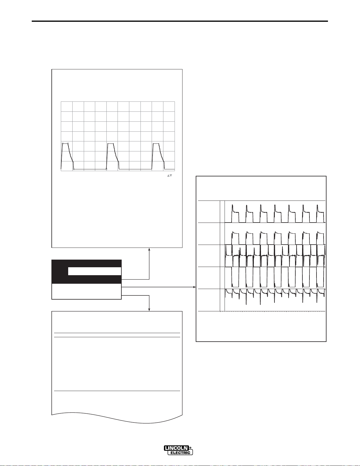
A.2 GMAW PULSE OVERVIEW
Figure A-1 illustrates the variables of the GMAW-P welding process. Each of these variables can
be programmed into a weld table using the Wave Designer software. Figure A-2 shows how the
pulse waveform and the primary variables shape, detach and propel a weld droplet across the
arc.
For more details on each of these variables, refer to
and
Secondary Pulse Waveform Components
in paragraphs A.5 and A.6 of this appendix.
FIGURE A-1. PULSE WAVEFORM PARAMETERS.
PEAK TIME
TAILOUT
TIME
% OVERSHOOT
TAILOUT
SPEED
PEAK
RAMP-UP RATE
AMPS
1/FREQUENCY
File Tools Print Help
Pulse Waveform Editor
Adapt
About
AC.sco loaded
50
600
-20
250
1.2
3.0
.100
40
21
33.4
26.4
Short
Wire Feed Speed
Ramp Up Rate
Ramp Overshoot %
Peak Amps
Peak Time ms
Tailout Time
Tailout Speed
Stepoff Amps
Backgrd Amps
Backgrd Time
Frequency
Start
Status
Wave Designer Pro Off Line - pulse.swf
700
600
Edit
500
400
300
200
100
0
0 3 6 9 12 15 18 21 24 27 30
End
Primary Pulse Waveform Components
STEP-OFF
AMPS
BACKGROUND AMPS
BACKGROUND
TIME
27850026
Off Line Stand by
Adaptive
27850027
WAVE DESIGNER
Page 35

Appendix A A-3
PULSE WAVE SHAPING PRINCIPLES
FIGURE A-2. WELD DROPLET TRANSFER.
SPRAY TRANSITION
CURRENT
PEAK AMPS
TAILOUT
RAMP-UP RATE
BACKGROUND AMPS
T1 T2 T5T3 T4
WELD
DROPLET
TRANSFER
27850028
• From time T1 to T2: Background current maintains an arc, and a weld bead starts to
form.
• From time T2 to T3: Ramp-up current forms the weld droplet at the tip of the electrode.
• From time T3 to T4: Peak current and peak time separate the droplet and propel it
toward the weld surface. The arc width and transfer force are
controlled by peak current and peak time.
• From time T4 to T5: Tailout current controls the heat input to and agitation of the weld
puddle. Shorter tailout contributes less heat to the weld. (The level of
background current also affects the weld heat.)
• After time T5: The waveform repeats to start the weld droplet transfer process over
again.
EACH PULSE DELIVERS ONE DROPLET OF WELD MATERIAL
WAVE DESIGNER
27850029
Page 36

A-4 Appendix A
PULSE WAVE SHAPING PRINCIPLES
A.3 ADAPTIVE AND NON-ADAPTIVE MODE
To proficiently develop welding procedures using Wave Designer, the key concept of Adaptive
versus Non-Adaptive welding must be understood. Wave Designer allows the user to set the
machine into either adaptive or non-adaptive mode. During the wave design process both modes
will be used depending upon the step.
A.3.1 ADAPTIVE MODE
In normal synergic welding the Power Wave welds in the adaptive mode. As the stickout changes
due to variations in the workpiece or operator hand motion, the Power Wave “adapts” or changes
the pulse variables to maintain a constant arc length. This is illustrated in Figure A-3.
Since adaptive mode attempts to maintain a fixed arc length, this is the mode that you will use
when adjusting an optimal arc length. Refer to steps 3 and 4 “Adjust the Peak Volts” in the flow
chart of paragraph A.4. Note: This step must be performed with the Trim set equal to 1.0 on the
Power Wave machine.
A.3.2 NON-ADAPTIVE MODE
In non-adaptive mode, the Power Wave does not adapt the pulse variables to maintain a
constant arc length as the stickout varies. This is illustrated in Figure A-3.
Therefore, the non-adaptive mode is the mode that you use to develop the proper waveform
variables. If this is attempted in the adaptive mode, you will get erroneous results since the
machine will be attempting to change (adapt) these variables. Refer to step 2 “Adjust Pulse
Variables at Fixed Stickout” in the process flow chart, Figure A-4.
NOTE: During this step of the wave design process, it is important to manually hold a constant
stickout.
FIGURE A-3. FIXED STICKOUT (NON-ADAPTIVE) VS.
OPTIMAL ARC LENGTH (ADAPTIVE).
ADAPTIVE
ARC LENGTH
=
ARC LENGTH
STICKOUT
2
1
1
ARC
LENGTH
STICKOUT
1
2
ARC
LENGTH
NON-
ADAPTIVE
ARC LENGTH
=
ARC LENGTH
STICKOUT
2
1
1
LENGTH
ARC
STICKOUT
1
2
ARC
LENGTH
27850031
2
2
WAVE DESIGNER
Page 37

Appendix A A-5
PULSE WAVE SHAPING PRINCIPLES
A.4 PULSE WAVE DESIGN PROCESS
The Wave Designer software interfaces with the welding machine controller to permit real time
communication of pulse wave design changes. Refer to paragraph 2.3 for equipment interface
connections.
Use the following wave design process to customize a standard wave shape. The process is
summarized in the following flowchart. The flowchart is followed by a detailed process
description. To ensure that the design process creates a wave shape suitable for your weld
application, we recommend that you perform all editing functions in the order presented. Where
an editing function is described as optional and you choose not to perform the edit function,
proceed to the next edit function in the design process.
FIGURE A-4. PROCESS FLOWCHART.
PROCESS FLOW: REFERENCE
PARAGRAPH:
Select a Waveform
from Memory
Mode = OFF
(SEE APPENDIX A)
A-4.1
GO FIGURE
Select Workpoint
Set Powerwave WFS
Set Trim = 1.00
Set Arc Control = OFF
Set NO-ADAPT
Adjust Pulse
Variables at
Fixed Stickout
Set ADAPT
Adjust Peak Volts
and
Adaptive Type
Adjust Optional
Variables
(if needed)
GO FIGURE
A-4.2 Step 1
A-4.2 Step 2
A-4.2 Steps 3 & 4
A-4.2 Steps 5, 6, & 7
Save File to Disk; Develop Next Workpoint
A-4.2 Step 8
Save File to Disk
Download File to Welding
Machine Memory
Section 3, paragraph 3.4
27850021
WAVE DESIGNER
Page 38

A-6 Appendix A
PULSE WAVE SHAPING PRINCIPLES
A.4.1 SELECTING A STARTING WAVE SHAPE
When customizing a waveform for a specific welding application, we recommend that you use a
waveform in an existing weld file. An existing weld file can be selected from the systemWeldFiles
folder in the Wave Designer directory as follows:
a. Click on a standard wave shape from the systemWeldFiles folder. Use the load file option in
the File menu to download the selected file to the Pulse Waveform Editor.
NOTE: The welding machine’s controller memory is allocated 10 weld mode slots (modes 155 to
164) for the storage of custom weld designs. No more than ten custom weld modes can
be downloaded to the welding machine. You cannot upload a custom weld from the
welding machine, but you can overwrite any or all of your allotted weld file memory
locations.
b. In Waveform Editor, select the Save Waveform As ... option from the File menu.
CAUTION
Failure to use the Save Waveform As... option to copy the standard wave shape
will result in changes to the standard wave shape. Make sure you assign a
unique file name to a copy of the standard wave shape before making any
waveform changes. Make backup copies of all original wave shape files as well
as the custom wave shapes you create.
c. When prompted, type in a unique filename for the new waveform. Select OK to assign the
new file name to the waveform.
WAVE DESIGNER
Page 39

Appendix A A-7
PULSE WAVE SHAPING PRINCIPLES
A.4.2 CUSTOMIZING THE WAVE SHAPE
If customizing your first wave shape, perform the wave shaping exercises provided at the back of
this section to get thoroughly acquainted with wave shaping. Thereafter, refer to the following
wave shaping procedure.
1. Select a Workpoint
a. Select a workpoint from the Wire Feed Speed pulldown menu. The first workpoint selected
should be in the midrange of the expected Wire Feed Speeds to be used for the weld
application. If you are uncertain of the WFS range, we recommend selecting 150 or 200
in./min. as a first workpoint.
NOTE: You can edit one or more workpoints to values other than the defaults.
However, the listing of wire feed speeds displayed must be the same or
increasing from top to bottom. All twelve wire feed speeds must be assigned
values, but multiple workpoints can share the same value.
The reason you would edit multiple workpoints to the same value would be to
limit the range of WFS or to develop fewer than twelve workpoints.
WorkPoint Editor
WorkPoint Editor
50 700
0
80 850
1
110 1000
2
150 1200
3
205
4
300
5
400
6
600
7
inch / min meter / min
b. Set the welding machine’s wire feed speed equal to the selected workpoint setting.
8
9
10
11
Go Figure
28750032
c. Verify that the power source control box Weld Mode is set for an OFF readout at the LED
display and that the arc control is OFF.
WAVE DESIGNER
Page 40

A-8 Appendix A
PULSE WAVE SHAPING PRINCIPLES
2. Open the Adaptive Loop / Find the Optimal Arc Characteristics
Use the following weld trials and adjustment sequence to tune the selected waveform for your
weld application at the designated workpoint (wire feed speed). Weld trials and adjustments are
more easily performed with one person welding while you adjust the waveform parameters at the
computer terminal.
a. Click on the button to open the Adapting
Stickout screen. Select the No Adapt option to open
the adaptive loop of the welding machine. The
Adapting Stickout
Adapting Stickout
For Wire Feed Speed
150
adaptive indicator on the editor screen will change to
No Adapt, indicating that the welding machine is in an
No Adapt: Maintain constant wire extension
open-loop, non-adaptive, condition.
Adaptive: Maintain constant arc length
NOTE: The adaptive loop must be open to prevent the
welding machine from making adaptive responses
to the wave shape changes. If the adaptive loop is
Adaptive Type
PeakAmp 10%, Stepoff 30%, Background 30%, Freq 45%
Fresa
closed, observations of how the welding machine
responds to the wave shape changes will be false.
Peak Voltage
30.0
Failure to open the adaptive loop of the welding
machine will inhibit the development of a
successful waveform for your welding application.
Inductance
2.625
27850033
b. Set the PowerFeed Trim control for a readout of 1.00. This will ensure that the wave shape
is designed at the midrange of the trim adjustment capability. The welding machine’s trim
control allows the welder to adjust the arc length between 0.5 to 1.5 (50% to 150%) times
the established arc length adjustment factor.
c. Maintain a constant stickout. The stickout should be equal to the expected average of the
welding application. We recommend about 5/8 in. to 3/4 in. (16 mm to 19 mm) electrical
stickout.
d. While welding a trial weld bead, adjust the pulse variables (peak current, peak time,
background current, frequency, etc.) to achieve a desired droplet transfer with a fixed 5/8 in.
to 3/4 in. (16 mm to 19 mm) stickout at the selected wire feed speed. Refer to paragraph
A.5.
e. With the stickout at a fixed setting, make trail welds during each adjustment so you can
directly observe the effect of the adjustments in the arc and resulting weld. Adjust the
variables as needed to achieve the desired weld transfer at the fixed stickout.
PEAK TIME
TAILOUT
TIME
% OVERSHOOT
TAILOUT
SPEED
STEP-OFF
AMPS
PEAK
RAMP-UP RATE
AMPS
BACKGROUND AMPS
BACKGROUND
TIME
1/FREQUENCY
27850034
WAVE DESIGNER
Page 41

Appendix A A-9
PULSE WAVE SHAPING PRINCIPLES
3. Close the Adaptive Loop / Adjust the Peak Voltage
a. If the adaptive stickout window is not open, click on the button to open the
window. Select the adaptive option to close the adaptive loop. Verify that the adaptive
button lights up.
NOTE: When on-line with the adaptive loop closed, the wave shape parameters will be adapted
(change) to maintain constant arc length. Adjusting one parameter in Wave Designer
often forces the adaptive feature to modify other wave shape parameters. The adaptive
nature of the program may be noticed when editing the parameters; changing one
parameter value causes other parameter values to change in response. We recommend
not changing pulse variables in the adaptive mode.
b. While the adaptive loop is closed, the peak voltage value displayed in the adaptive stickout
window is adjustable. While welding a trial bead, adjust the peak voltage for an optimal arc
length.
c. If desired, adjust the inductance value to achieve the desired weld pinch. If the inductance
value is set too high, it will limit the rate of current change and may limit the ramp-up rate
and tailout speed.
4. Select an Adaptive Type (Optional)
a. Click on the button on the Waveform Editor screen to view the Adapting Stickout
screen. Click on the arrow in the adaptive type box to display the adaptive types listing.
b. Select each adaptive type in-turn and perform a trial weld. After performing a trial weld for
each adaptive type, select the adaptive type best suited to the wire feed speed. A brief
summary of the adaptive type characteristics is presented in Table A-1.
TABLE A-1. ADAPTIVE TYPE CHARACTERISTICS.
Adaptive Type *Characteristics
Sandia Stepoff and background
30%, frequency 45%
Fresa
Manzana
Naranja
Peak current 10%, stepoff
and background 30%,
frequency 45%
Peak current 20%, stepoff
and background 10%,
frequency 30%
Peak current and time 10%,
stepoff and background
10%, frequency 30%
Application
lower wire feed speeds and where consistent
pulse values for droplet detachment are
required
intermediate wire feed speeds
high wire feed speeds; peak current is the
controlling variable
where highest range of peak adaptive control
is required
Mora
*Each adaptive type specifies which parameters are being adapted and the sensitivity of adaptiveness for
each parameter. For example, Mora type adapts only one parameter — frequency — at a sensitivity level
of 60%. In developing waveforms, try each adaptive type to determine the most desired result.
Frequency 60%
WAVE DESIGNER
typical for most pulse GMAW welding
machines
Page 42

A-10 Appendix A
PULSE WAVE SHAPING PRINCIPLES
5. Adjust the Start Control Parameters (Optional)
The start control parameters can be adjusted to define how the welding machine will respond
when the arc is struck.
To view the start control window, click on the button on the Waveform Editor screen.
Adjust the start control parameters to accommodate your welding application and per the
following parameter descriptions.
Start Control - Pulse
Start Control
STRIKE
PEAK AMPS
STRIKE
PEAK TIME
For Wire Feed Speed
Stage 1 : Wire Run In
Open Circuit Volt
150
48.0
AVERAGE
START
AMPS
Stage 2 : Striking Pulse
Strike Peak Time
Strike Peak Amps
2.0
550.0
@
OPEN
CIRCUIT
START
VOLTS
START TIME
Stage 3 : Arc Length Control
Start Volt
Start Time
28.0
50
VOLTS
ARC
STRIKE
Stage 4 : Current Control
Start Amps
50
Open circuit voltage: Sets the power source output voltage for the torch idle condition (the
welding machine is on, but not welding).
Strike peak amps: Adjust this parameter to set the peak level for the arc-strike current spike.
Strike peak time: Adjust this parameter to set the duration of peak current for the arc-strike
current spike.
Starting volts: Adjust this parameter to set the gun voltage to be maintained during the arc
starting routine.
27850035
Starting time: Adjust this parameter to set the duration of the arc starting routine.
Starting amps: Adjust this parameter to set the average current level during starting.
WAVE DESIGNER
Page 43

Appendix A A-11
PULSE WAVE SHAPING PRINCIPLES
6. Adjust the Shorting Control Parameters (Optional)
The shorting control parameters can be adjusted to define how the welding machine will respond
when the arc shorts to the weld puddle.
To view the shorting control window, click on the button on the Waveform Editor screen.
Adjust the shorting control parameters to accommodate your welding application and per the
following parameter descriptions.
PINCH CURRENT
RISE PLATE
Shorting Control
Shorting Control
For Wire Feed Speed
AMPS
Short Detect Volt
VOLTS
SHORT
DETECT
VOLTS
Short detect voltage: Adjust this parameter to set the detect voltage level that will start the
shorting response.
Pinch current rise rate (shorting response): Adjust this parameter to set the current rise rate that
will be used to clear a short.
Arc reestablish volts: Adjust this parameter to set the detect voltage level that will end the
shorting response.
ARC
REESTABLISH
VOLTS
Pinch Current Rise Rate
Arc Restablish Volt
50
5
55.18
15
27850036
WAVE DESIGNER
Page 44

A-12 Appendix A
PULSE WAVE SHAPING PRINCIPLES
7. Adjust the End Condition Parameters (Optional)
The end condition parameters can be adjusted to define how the welding machine will respond at
the end of a weld application.
To view the end condition window, click on the button on the Waveform Editor screen.
Adjust the end condition parameters to accommodate your welding application and per the
following parameter descriptions.
END AMPS
End Conditioning
End Conditioning
For Wire Feed Speed
End Amp
END
TIME
End amps: Adjust this parameter to establish the peak amperage of the wire conditioning pulse.
The wire conditioning pulse knocks the last weld droplet from the electrode at the end of a weld.
End time: Adjust this parameter to set the duration of the ending pulse.
Amp • Time: This parameter indicates the power of the ending pulse.
End Time
Amp * Time
50
550.0
2.5
1375.0
27850037
WAVE DESIGNER
Page 45

Appendix A A-13
PULSE WAVE SHAPING PRINCIPLES
8. “Go Figure” / Make the Waveform Synergic
Weld synergy is established by shaping the 2nd and all subsequent workpoints. Being synergic,
the waveform parameters automatically adjust to programmed data table values. The data table
values are unique for selected wire feed speeds. Thereby, the output of the power source
changes in response to changes in the wire feed speed, as controlled by the PowerWave’s WFS
encoder setting. The process of making the waveform synergic involves two procedures;
developing the 2nd workpoint and workpoints interpolation.
Developing the 2nd Workpoint
Develop the second workpoint in the same manner as the first.
WorkPoint Editor
WorkPoint Editor
80 700
0
80 700
1
110 700
2
150 700
3
205
4
300
5
400
6
600
7
inch / min meter / min
8
9
10
11
Go Figure
FIXED VALUE
INTERPOLATED/
EXTRAPOLATED VALUE
WP5
WP3
WP4
WP2
WORKPOINT VARIABLE
WP0, 1
WIRE FEED SPEEDS
WP8, 9, 10, 11
WP7
WP6
28750038
NOTE: In the workpoint window where workpoints 9 through 11 are not selected, they are
assigned the value of workpoint 8. This sets 700 as the upper limit on the operative
wire feed speeds.
Workpoints Interpolation
After shaping the second waveform, open the workpoint editor and click on the
button. Wave Designer interpolates the waveform parameters for each unchecked (not
selected) wire feed speed. These steps can be repeated multiple times to fine tune all the
workpoints. The set (fixed) wire feed speeds are those indicated (checked) in the workpoints
listing. Go Figure will interpolate/extrapolate between/from set workpoints.
WAVE DESIGNER
Page 46

A-14 Appendix A
PULSE WAVE SHAPING PRINCIPLES
A.5 PRIMARY PULSE WAVEFORM COMPONENTS
The following paragraphs describe how peak current, peak time, frequency, and background
current effect weld droplet transfer.
A.5.1 PEAK CURRENT AND PEAK TIME
A combination of peak current and peak time, Figure A-6, applies a force to detach the weld
droplet from the electrode and propel it across the arc. Transition current is the current level
required to achieve weld droplet formation. In order to achieve weld droplet transfer, the peak
current must always be above the spray transition current.
FIGURE A-6. PEAK CURRENT AND PEAK TIME.
PEAK TIME
PEAK
PEAK TIME
PEAK
FIXED
STICKOUT
SMALLER LARGER
DROPLET DROPLET
LONGER SHORTER
ARC ARC
27850039
WAVE DESIGNER
Page 47

Appendix A A-15
PULSE WAVE SHAPING PRINCIPLES
A.5.2 FREQUENCY
Frequency, Figure A-7, is the number of pulses per second or, in theory, the number of weld
droplets per second. Since increasing the frequency generates more pulses in a given time
period, higher frequencies generate higher average current levels.
FIGURE A-7. FREQUENCY.
AVERAGE
CURRENT
BACKGROUND
CURRENT
T
1
LARGER
DROPLETS
T2
T3
AVERAGE
CURRENT
BACKGROUND
CURRENT
SMALLER
DROPLETS
LONGER
ARC
SHORTER
T1
ARC
T2
T3
27850040
A.5.3 BACKGROUND CURRENT
The background current, Figure A-7, is set to maintain a desired plasma arc between weld
droplet transfers and to control the heat input to the weld system.
WAVE DESIGNER
Page 48

A-16 Appendix A
PULSE WAVE SHAPING PRINCIPLES
A.6 SECONDARY WAVEFORM PARAMETERS
A.6.1 RAMP-UP RATE
The ramp-up rate is the speed of current climb from the background current level to the peak
current level. Faster ramp-up rates tend to produce a plasma plume that quickly surrounds the
end of the next droplet.
A.6.2 RAMP OVERSHOOT %
The ramp overshoot % can be set from -100% to +100% of the peak amps value. Positive %
overshoot is commonly used to harden the arc. Negative % overshoot (undershoot) is used to
soften the arc for welding. Ramp overshoot can also be used to compensate for variations in the
length of the ground lead which alters the output inductance of the power source.
A.6.3 TAILOUT SPEED
The tailout speed is the rate of amperage decrease from the peak current level to the step-off
current level. Tailout speed decreases exponentially. Tailout speed affects the amount of heat
put into the system just after droplet transfer. Slow tailout speeds (near 0) apply more heat to the
weld system. Rapid tailouts are more likely to short circuit the electrode to the work.
A.6.4 TAILOUT TIME
The tailout time is the duration of tailout. Longer tailout times maintain the system heat longer.
Shorter tailout times can force the output to reach the background current level. Note that the
adaptive loop can not force the wave period (1/pulse frequency) into the tailout region. We
recommend setting the background time long enough to allow the adaptive loop to work.
A.6.5 STEP-OFF AMPERAGE
Step-off amperage is the target current level reached during tailout. The step-off amperage must
be higher than the background current.
A.6.6 BACKGROUND TIME
Background time is the duration of background current. Background time is equal to the
waveform period minus the duration of ramp up, peak time, and tailout. Increasing the
background time decreases the pulse frequency. We recommend setting the background time
long enough to allow the adaptive loop to work.
FIGURE A-8. PULSE WAVEFORM PARAMETERS.
TAILOUT
TIME
TAILOUT
SPEED
STEP-OFF
AMPS
BACKGROUND AMPS
% OVERSHOOT
RAMP-UP RATE
PEAK TIME
PEAK
AMPS
1/FREQUENCY
WAVE DESIGNER
BACKGROUND
TIME
Page 49

Appendix A A-17
PULSE WAVE SHAPING PRINCIPLES
A.7 APPLICATION EXERCISE
This application exercise steps the user through the development of a basic PowerWave welding
program using Wave Designer. Your application most likely will vary from this example but the
concepts outlined are recommended for all development work.
If you would like to follow along with this example, use the following set up:
Machine: PowerWave 455, PowerFeed 10, Magnum 400 gun and cable, miscellaneous other
parts to complete welding cell
Wire: 0.035 L-56
Gas: 90% Argon 10% CO
Computer: See Section 2 of this manual for minimum requirements and connection diagrams.
Click on the Wave Designer icon to start the program.
For this example, we developed a program to run wire feed speeds between 150 in/min. and
300 in/min. The user may want to develop more workpoints for practice.
Before starting the waveshape development process, confirm that the consumables are working
properly with the welder. We recommend using a standard waveshape such as mode 5 to
confirm that the welding system performs under normal conditions before attempting to develop
waveshapes.
2
1.
Select a wave shape.
(From the tool bar, select
‘File’, ‘Open Waveform’.) For this exercise, select
the “pulse.swf” wave shape. This wave shape is
automatically loaded when the Wave Designer
program is first used. Generally, the user should
choose a waveshape file that has the closest
welding performance to the intended application.
Pick a wire feed speed
2.
from the Wire Feed
Speed pulldown menu. We started with the 150
in/min. WFS. Also, be sure to set the PowerFeed’s
wire feed speed to the same WFS as the selected
workpoint and set the trim to 1.00. (In this exercise,
the WFS is 150 in/min.)
File
Tools Print Help
Open Waveform Ctrl+O
Save Waveform As ...
Save Waveform
File Tools Print Help
Ctrl+S
27850041
Pulse Waveform Editor
600
-7
280
50
80
110
150
205
300
400
600
700
27850047
Wire Feed Speed
Ramp Up Rate
Ramp Overshoot %
Peak Amps
WAVE DESIGNER
Page 50

A-18 Appendix A
PULSE WAVE SHAPING PRINCIPLES
3. Using the adaptive stickout window or the green
adaptive button on the status bar,
Adapt’
. The status bar at the bottom of the
select ‘No
screen should read:
. Close the “adapt” window (if
No Adapt: Maintain constant wire extension
Adapting Stickout
Adapting Stickout
For Wire Feed Speed
150
opened).
Adaptive: Maintain constant arc length
4. While welding,
improve welding performance.
constant 5/8 in. stickout (torch tip to work
adjust the pulse variables to
Maintain a
Adaptive Type
PeakAmp 10%, Stepoff 30%, Background 30%, Freq 45%
Fresa
distance.)
Peak Voltage
Inductance
Start Adapt Short End
30.0
2.625
27850042
Our Experiment: We found multiple droplet detachment with an arc length that was too long
at these waveform settings. To attain the proper droplet detachment, we reduced the peak
current value to 250 amps and found improved weld droplet transfer. But reducing the peak
current also caused the arc to be shorter.
Then we needed to lengthen the arc. We reduced the background time to 8.5 milliseconds,
thereby increasing the frequency. The result was a good arc length set at the fixed stickout
of 5/8 in. The droplet transfer was now acceptable and the arc length correct for this stick
out. With the pulse variables set, we could now proceed to make the PowerWave adaptive
(maintain a set arc length over a range of stickouts).
This was a simple application. It shows that the variables interact with each other. The
right solution for a given application may not be the right solution for another. Wave
Designer features great flexibility to manipulate the waveshape to suit specific applications.
5. Click on the button and select the
‘Adaptive’ mode.
(The status bar now
reads: .)
While making weld,
set the ‘Peak Voltage’
to
No Adapt: Maintain constant wire extension
Adapting Stickout
Adapting Stickout
For Wire Feed Speed
150
obtain the desired arc length at the 1.00 trim
setting.
Our Experiment: We found that a peak
voltage of 27.0 volts resulted in a useable arc
length. (In the “No Adapt” mode, welding with
a fixed 5/8 in. stickout, the actual voltage on
the PowerWave’s voltmeter read about 19
volts. When setting the peak voltage, the
average volts was also about 19 volts. Note
Adaptive: Maintain constant arc length
Adaptive Type
PeakAmp 10%, Stepoff 30%, Background 30%, Freq 45%
Peak Voltage
Inductance
Start Adapt Short End
Fresa
30.0
2.625
27850043
that the actual voltage readouts at the
welding machine will not be the same as the
peak voltage.)
WAVE DESIGNER
Page 51

Appendix A A-19
5003
PULSE WAVE SHAPING PRINCIPLES
6. The “Start”, “Short”, and “End” windows can
be adjusted at this time to optimize the
starting, shorting, and ending routines.
Our Experiment: We needed to adjust the
starting variables. With the feeder’s run-in
WFS set at 65 in/min, we set the starting
variables to control the starting routine. With
the assistance of ArcScope, we found good
settings with these values: start volt 21.0,
start time 35 milliseconds, and start current
180 amps. The OCV strike peak time and
amps were acceptable as set.
Start Control - Pulse
Start Control
For Wire Feed Speed
Stage 1 : Wire Run In
Open Circuit Volt
Stage 2 : Striking Pulse
Strike Peak Time
Strike Peak Amps
Stage 3 : Arc Length Control
Start Volt
Start Time
Stage 4 : Current Control
Start Amps
48.0
2.0
550
21.0
88
172
150
27850044
7. Click on the button to display the
WorkPoint Editor window. Check only those
wire feed speed points that have been
developed (only 150 in/min. at this point). The
WorkPoint Editor can also be used to change
the wire feed speed value of a workpoint.
Workpoints can have the same value but must
be in numerical order.
Select the button to set the wave
shape parameters for all workpoints equal to
the wave shape parameters of the 150 in/min.
workpoint. Close the WorkPoint Editor window.
WorkPoint Editor
WorkPoint Editor
50 700
0
80 850
1
110 1000
2
150 1200
3
205
4
300
5
400
6
600
7
inch / min meter / min
8
9
10
11
Go Figure
287
2
WAVE DESIGNER
Page 52

A-20 Appendix A
PULSE WAVE SHAPING PRINCIPLES
8. For a
second workpoint
we went to 300 in/min. Select the 300 in/min. wire feed speed
from the pulldown menu in Waveform Editor window. Reset the PowerFeed for 300 in/min.
with a 1.00 trim.
9. Open the adapting stickout window and select
the ‘No Adapt’ mode; close the window.
10. At lower wire feed speed settings, some users
like to fix the values of the peak variables. To
do this, check the boxes next to the peak
variables (ramp up rate, ramp overshoot %,
peak amps, peak time, and tailout). Perform
Pulse Waveform Editor
Wire Feed Speed
Ramp Up Rate
Ramp Overshoot %
Peak Amps
150
600
.0
250
Edit
weld trials and adjust the pulse wave shape
variables.
Our Experiment: At the higher wire feed
speed, we needed more heat to melt the
added wire. We took the background up to
75 amps and the background time down to
3.8 milliseconds. (The frequency also
changed due to the change to the
background time.) Welding trials indicated
Peak Time ms
Tailout Time
Tailout Speed
Stepoff Amps
Backgrd Amps
Backgrd Time
1.4
1.5
.100
25
20
8.3
27850045
that the droplets were transferring properly
and that the arc length was correct for the
5/8 in. (16 mm) stickout.
11. Set the mode to ‘Adaptive’. Make a trial weld to check the peak voltage setting.
Our Experiment: While welding we found that 27 volts was about right for the peak voltage.
Since the peak variables did not change, the peak voltage will remain about the same as
well. We also noticed that the average voltage increased from the value observed at
150 in/min. This increase is due to the higher frequency required for the higher wire feed
speeds.
WAVE DESIGNER
Page 53

Appendix A A-21
PULSE WAVE SHAPING PRINCIPLES
12. Open the “Edit” screen and select only those
WorkPoint Editor
workpoints that have been developed (150 and
300 in/min.). Select the button to
WorkPoint Editor
interpolate the remaining workpoints. The
function gives a estimation of the
values needed for the other wire feed speeds.
Each useable workpoint should be developed
separately.
Our Experiment: We tested the 205 in/min.
workpoint to confirm that its operation was
good. We checked the pulse variables in the
no adapt mode and the peak voltage in the
adaptive mode. The 205 in/min. workpoint
0
80 850
1
110 1000
2
150 1200
3
205
4
300
5
400
6
600
7
8
9
10
11
50 700
was acceptable without modifications. The
other workpoints in the program can be
inch / min meter / min
developed in a similar fashion. After we
completed developing the program, we
checked its performance across the range of
wire feed speeds.
Go Figure
28750046
13. The specific wire feed speed points of the program are now developed in the range of
150 in/min to 300 in/min. Check the full range of the program to confirm its synergic
operation.
Our Experiment: We started at 150 in/min. and while welding, ran the wire feed speed up to
300 in/min. The arc looked consistent across the range.
14. If desired, our new custom waveform could be ‘Saved As’ another file name and
downloaded into the PowerWave’s weld mode directory.
The new program is complete. To summarize, we performed the following sequence of tasks:
1. Set up the equipment.
2. Selected a program close to our application needs.
3. Selected a wire feed speed.
4. Make program “No Adapt” and set pulse variables.
5. Make program “Adapt” and set arc length.
6. Adjust the starting, shorting, ending routines as needed.
7. Use to interpolate and extrapolate values for the other wire feed speeds.
8. Choose the next wire feed speed to develop and go back to step 4.
9. Weld with the range of the program to confirm operation performance.
WAVE DESIGNER
Page 54

A-22 Appendix A
PULSE WAVE SHAPING PRINCIPLES
WAVE DESIGNER
Page 55

Appendix B B-1
STT WAVE SHAPING PRINCIPLES
B.1 APPENDIX OVERVIEW
This appendix provides a series of discussions on STT wave shaping principles and the
development of custom STT waveforms. The contents of this appendix are arranged as follows:
Paragraph No./Title Contents Description
B.2 STT Overview How the STT waveform transfers weld droplets to the
weld surface
B.3 STT (Surface Tension Transfer) How WFS and wave shape parameters effect welding
B.4 STT Wave Design Process Flowchart and step by step descriptions of the STT
wave design process
B.5 Primary STT Waveform How peak current, background current, and tailout
Components speed effect weld droplet transfer
B.6 Secondary STT Waveform How pinch start, pinch/peak, peak time, and dV/dt
Components detect effect weld droplet transfer
B.7 Application Exercise Sample development of an STT welding program using
Wave Designer.
WAVE DESIGNER
Page 56

B-2 Appendix B
STT WAVE SHAPING PRINCIPLES
B.2 STT OVERVIEW
Figure B-1 illustrates the variables of the STT welding process. Each of these variables can be
programmed into a weld table using the Wave Designer software. Figure B-2 shows how the
STT waveform and the primary variables produce a weld.
For more details on each of these variables, refer to
Secondary STT Waveform Components
in paragraphs B.5 and B.6 of this appendix.
FIGURE B-1. STT WAVEFORM PARAMETERS.
AMPERES
PINCH START
BACKGROUND AMPS
dV/dt CALCULATE
Primary STT Waveform Components
PEAK TIME
PEAK AMPS
TAILOUT
SPEED
TIME
and
File Tools Print Help
STT Waveform Editor
Wire Feed Speed
Peak Amps
Backgrd Amps
Tailout Speed
Pinch Start
Pinch | Peak
Peak Time
dV | dt detect
Start About
Status
90
200
60
.500
140
.70
1.0
14.00
Explain
read template2.map
Wave Designer Pro Off Line - stt.swf
500
400
Edit
300
200
100
0
012345678910
Off Line Stand by
27850057
WAVE DESIGNER
Page 57

Appendix B B-3
STT WAVE SHAPING PRINCIPLES
FIGURE B-2. WELD DROPLET TRANSFER.
PEAK
AMPS
TA I L OU T
PINCH AMPS
BACKGROUND AMPS
T
0
T
T
1
2
T
3
T
5
T
6
T
7
27850060
• From time T0to T1: Background current is a steady-state current level, between 50 and
(Background Current) 100 Amps that maintains an arc to form a weld bead.
• From time T
to T2: An arc voltage detector indicates that the arc is shorted; background
1
(Ball Time) current is reduced for approximately 0.75 milliseconds.
• From time T
to T3: High current is applied to speed the transfer of molten metal to the
2
(Pinch) weld puddle. A dV/dt calculation indicates when fuse separation is
about to occur; current is reduced to 50 Amps.
• Time T
: Fuse separation occurs at low current. Time T4is a function of
4
(Fuse Separation) voltage, and not indicated on the amperage waveform.
• From time T
to T6: A period of high arc current that melts the electrode back.
5
(Plasma Boost)
• From time T
to T7: Arc current is reduced from Peak Amps to the Background current
6
(Plasma) level.
WAVE DESIGNER
Page 58

B-4 Appendix B
p
STT WAVE SHAPING PRINCIPLES
B.3 STT (SURFACE TENSION TRANSFER)
The Invertec STT power source is a high-frequency, current-controlled machine that delivers
power to the arc based on immediate arc requirements. The Invertec STT produces large
electrode current changes within microseconds. It operates in the short-circuiting welding mode.
The electrode current supplied by the power source is guided by the arc voltage state. An
ordered sequence of events controls the current throughout the droplet transfer process. The
electrode current and voltage waveforms for a typical welding cycle are shown in Figure B-3.
Following Figure B-3 are detailed descriptions of the STT welding cycle events.
FIGURE B-3. ELECTRODE CURRENT AND VOLTAGE WAVEFORMS
FOR A TYPICAL STT WELDING CYCLE.
Surface Tension Transfer™
Electrode
Electrode to
work volts
Electrode
Amperes
T0– T
1
– T
T
1
2
TTTTT
0
A background current between 50 and 100 Amps is delivered to the arc prior
to shorting of the electrode to the weld puddle. Background current is a steadystate current level that serves two purposes. First, the background current
supplies power to the arc to maintain the fluidity of the molten drop at the end of
the electrode. (Failure to supply the minimum required current causes the upper
portion of the molten ball to freeze. As more of the ball solidifies, arc instability
and finally stubbing occurs.) Secondly, the background current level greatly
effects plate heating.
Ball time occurs when the electrode initially shorts at the background current
level. When the Invertec’s arc voltage detector circuit signals that the “arc” is
shorting out, the background current is immediately reduced for approximately
0.75 milliseconds. The rapid current drop promotes good electrical contact and
“wetting” of the ball to the weld puddle. Wetting prevents an “incipient short”,
wherein the ball is violently repelled from the weld puddle, breaking apart and
causing spatter.
TT T
12
345 6 7
Time
27850063
WAVE DESIGNER
Page 59

Appendix B B-5
STT WAVE SHAPING PRINCIPLES
T2– T
– T
T
3
– T
T
5
– T
T
6
3
The pinch mode applies an increasing, dual-slope ramp of current to the
shorted electrode. The dual slope ramp of current accelerates the transfer of
molten metal by the electric pinch forces. The pinch force is directly proportional
to the square of the pinch current.
5
dV/dt is the rate of shorted-electrode voltage change per unit time. On-going
dV/dt calculations are performed electronically during the pinch mode. Due to the
high resistance of molten iron, the electrode-to-work voltage never reaches zero.
Near fuse separation at T
raises the dV/dt value to a designated maximum. The
4
power source immediately reduces the arc current to 50 Amps. The current drop
occurs before the shorted electrode separates. The T4event indicates that fuse
separation has occurred, but at a very low current.
6
Immediately following separation of the electrode from the weld puddle, peak
current occurs. Peak current is a period of high arc current. The electrode is
quickly saturated by this current and melts back. The jet forces acting upon the
weld puddle (cathode) depress the molten surface, increasing the arc length and
thereby minimizing the possibility of the electrode shorting prematurely. Peak
current is maintained for approximately 1 to 2 milliseconds. Excessive power
would melt too much electrode and cause weld spatter. Even at low power, the
shape of the melted electrode at this point is very irregular.
7
Plasma is the final period when the arc current is reduced exponentially from the
peak current level to the background Ievel. The exponential current drop
mechanically dampens the weld pool agitation produced during peak current.
WAVE DESIGNER
Page 60

B-6 Appendix B
STT WAVE SHAPING PRINCIPLES
B.4 STT WAVE DESIGN PROCESS
The Wave Designer software interfaces with the welding machine controller to permit real time
communication of STT wave design changes. Refer to paragraph 2.3 for equipment interface
connections.
Use the wave design process to customize a standard wave shape. The process is summarized
in Figure B-4. The flowchart is followed by a detailed process description. To ensure that the
process creates a wave shape suitable for your weld application, we recommend that you
perform all editing functions in the order presented. Where an editing function is described as
optional and you choose not to perform the edit function, proceed to the next edit function in the
design process.
FIGURE B-4. PROCESS FLOWCHART.
PROCESS FLOW: REFERENCE
PARAGRAPH:
Select a Waveform
from Memory
Mode = OFF
(SEE APPENDIX B)
B-4.1
GO FIGURE
Save File to Disk
Select Workpoint
Set Invertec = WFS
Trim = 1.00
STT Variables
ADJUST
Adjust Optional
Variables
GO FIGURE
B-4.2 Step 1
B-4.2 Step 2
B-4.2 Step 3
Save File to Disk; Develop Next Workpoint
B-4.2 Step 4
Download File to Welding
Machine Memory
Section 3, paragraph 3.4
27850061
WAVE DESIGNER
Page 61

Appendix B B-7
STT WAVE SHAPING PRINCIPLES
B.4.1 SELECTING A STARTING WAVE SHAPE
When customizing a waveform for a specific welding application, we recommend that you use a
waveform in an existing weld file. An existing weld file can be selected from the systemWeldFiles
folder in the Wave Designer directory as follows:
a. Click on a standard wave shape from the systemWeldFiles folder. Use the load file option in
the File menu to download the selected file to the STT Waveform Editor.
NOTE: The welding machine’s controller memory is allocated 10 weld mode slots (modes 155 to
164) for the storage of custom weld designs. No more than ten custom weld modes can
be downloaded to the welding machine. You cannot upload a custom weld from the
welding machine, but you can overwrite any or all of your allotted weld file memory
locations.
b. In Waveform Editor, select the Save Waveform As ... option from the File menu.
CAUTION
Failure to use the Save Waveform As... option to copy the standard wave shape
will result in changes to the standard wave shape. Make sure you assign a
unique file name to a copy of the standard wave shape before making any
waveform changes. Make backup copies of all original wave shape files as well
as the custom wave shapes you create.
c. When prompted, type in a unique filename for the new waveform. Select OK to assign the
new file name to the waveform.
WAVE DESIGNER
Page 62

B-8 Appendix B
STT WAVE SHAPING PRINCIPLES
B.4.2 CUSTOMIZING THE WAVE SHAPE
If customizing your first wave shape, perform the wave shaping exercises provided at the back of
this section to get thoroughly acquainted with wave shaping. Thereafter, refer the following wave
shaping procedure.
1. Select a Workpoint
a. Select a workpoint from the Wire Feed Speed pulldown menu. The first workpoint selected
should be in the midrange of the expected Wire Feed Speeds to be used for the weld
application. If you are uncertain of the WFS range, we recommend selecting 150 or 200
in/min. as a first workpoint.
NOTE: You can edit one or more workpoints to values other than the defaults.
However, the listing of wire feed speeds displayed must be the same or
increasing from top to bottom. All four wire feed speeds must be assigned
values, but multiple workpoints can share the same value.
The reason you would edit multiple workpoints to the same value would be to
limit the range of WFS or to develop fewer than four workpoints.
WorkPoint Editor
WorkPoint Editor
90
0
170
1
200
2
225
3
inch / min meter / min
Go Figure
28750048
b. Set the welding machine’s wire feed speed equal to the selected workpoint setting.
c. Verify that the control box Weld Mode is set for an OFF readout at the LED display and that
the arc control is OFF.
WAVE DESIGNER
Page 63

Appendix B B-9
STT WAVE SHAPING PRINCIPLES
2. Find the Optimal Arc Characteristics
Use the following weld trials and adjustment sequence to tune the selected waveform for your
weld application at the designated workpoint (wire feed speed). Weld trials and adjustments are
more easily performed with one person welding while you adjust the waveform parameters at the
computer terminal.
a. Set the Invertec Trim control for a readout of 1.00. This will ensure that the wave shape is
designed at the midrange of the trim adjustment capability. The welding machine’s trim
control allows the welder to adjust the arc length between 0.5 to 1.5 (50% to 150%) times
the established arc length adjustment factor.
b. Maintain a constant stickout. The stickout should be equal to the expected average of the
welding application. We recommend about 5/8 in. to 3/4 in. (16 mm to 19 mm) electrical
stickout.
c. While welding a trial weld bead, adjust the waveform variables (peak current, background
current, tailout, etc.) to achieve a desired droplet transfer with a fixed 5/8 in. to 3/4 in.
(16 mm to 19 mm) stickout at the selected wire feed speed. Refer to paragraph B.5.
d. With the stickout at a fixed setting, make trail welds during each adjustment so you can
directly observe the effect of the adjustments in the arc and resulting weld. Adjust the
variables as needed to achieve the desired weld transfer at the fixed stickout.
NOTE: Wire feed speed controls the deposition rate. Peak current controls the arc length.
Background current controls the bead contour, and tailout adjusts power (heat) in the
arc. For optimum spatter control, the arc should be focused on the weld puddle.
PEAK TIME
PEAK AMPS
AMPERES
PINCH START
BACKGROUND AMPS
dV/dt CALCULATE
TIME
TAILOUT
SPEED
27850059
WAVE DESIGNER
Page 64

B-10 Appendix B
STT WAVE SHAPING PRINCIPLES
3. Adjust the Start Control Parameters (Optional)
The start control parameters can be adjusted to define how the welding machine will respond
when the arc is struck.
To view the start control window, click on the button on the Waveform Editor screen.
Adjust the start control parameters to accommodate your welding application and per the
following parameter descriptions.
Start Control - STT
STT Start Control
STRIKE
PEAK I
OPEN
CIRCUIT
VOLTS
TIME
ARC
STRIKES
STRIKE
START TIME
STRIKE I
AVERAGE
START
AMPS
@
START
VOLTS
For Wire Feed Speed
Stage 1: Wire Run In
Open Circuit Volt
Stage 2: Striking Pulse
Strike Peak I
Strike Time
Strike |
Stage 3: Molten Ball Formation
Start Volt
Start Time
90
42.00
750
1.0
700
23.00
20.0
27850058
Open circuit voltage: Sets the power source output voltage for the torch idle condition (the
welding machine is on, but not welding).
Strike time: Adjust this parameter to set the duration of peak current for the arc-strike current
spike.
Strike Peak I & Strike I: Adjust these parameters to set the peak current level for the arc-strike
current spike.
The Strike Peak I is set to some level (e.g. 50 amps) higher than the Strike I to improve current
step responsiveness. In other words, the actual current has a tendency of lagging behind in rapid
stepping of commanded current. A higher initial Strike Peak I is designed to overcome this
problem.
Starting volts: Adjust this parameter to set the gun voltage to be maintained during the arc
starting routine.
Starting time: Adjust this parameter to set the duration of the arc starting routine.
WAVE DESIGNER
Page 65

Appendix B B-11
STT WAVE SHAPING PRINCIPLES
4. “Go Figure” / Make the Waveform Synergic
Weld synergy is established by shaping the 2nd and all subsequent workpoints. Being synergic,
the waveform parameters automatically adjust to programmed data table values. The data table
values are unique for selected wire feed speeds. Thereby, the output of the power source
changes in response to changes in the wire feed speed, as controlled by the Invertec’s WFS
encoder setting. The process of making the waveform synergic involves two procedures;
developing the 2nd workpoint and workpoints interpolation.
Developing the 2nd Workpoint
Develop the second workpoint in the same manner as the first.
WorkPoint Editor
WorkPoint Editor
90
0
170
1
200
2
225
3
FIXED VALUE
INTERPOLATED/
EXTRAPOLATED VALUE
WP3
WP2
WP1
WORKPOINT VARIABLE
inch / min meter / min
Go Figure
WP0
WIRE FEED SPEEDS
28750056
Workpoints Interpolation
After shaping the second waveform, open the workpoint editor and click on the
button. Wave Designer interpolates the waveform parameters for each selected wire feed
speed between the first and second developed workpoints. These steps can be repeated multiple
times to fine tune all the workpoints. The set (fixed) wire feed speeds are those indicated
(checked) in the workpoints listing. Go Figure will interpolate/extrapolate between/from set
workpoints.
WAVE DESIGNER
Page 66

B-12 Appendix B
STT WAVE SHAPING PRINCIPLES
B.5 PRIMARY STT WAVEFORM COMPONENTS
The following paragraphs describe how peak current, background current, and tailout effect weld
droplet transfer.
B.5.1 PEAK CURRENT
The peak current control acts similar to an “arc pinch” control. Peak current serves to establish
the arc length and promote good fusion. Higher peak current levels will cause the arc to broaden
momentarily while increasing the arc length. If set too high, long arc lengths will inhibit travel
speed. Setting this level too low will cause instability and wire stubbing. In practice, this current
level should be adjusted for minimum spatter and puddle agitation.
ADJUST ARC LENGTH WITH PEAK CURRENT
OPTIMUMLOW HIGH
NOTE: In 100% CO2shielding gas applications, the peak current level should be set greater
than in a similar application using a high percentage Argon blend. Longer initial arc
lengths with 100% CO2are required to reduce spatter.
27850064
WAVE DESIGNER
Page 67

Appendix B B-13
STT WAVE SHAPING PRINCIPLES
B.5.2 BACKGROUND CURRENT
The Background current controls the overall heat input to the weld. Adjusting this level too high
will form a large droplet resulting in globular type transfer and increased spatter. Adjusting this
level too low will cause wire stubbing and poor wetting of the weld metal.
ADJUST BEAD SHAPE USING BACKGROUND CURRENT
OPTIMUMLOW HIGH
24850065
NOTE: Applications using 100% CO2require less background current than similar procedures
using high Argon blends. This is due to greater heat generated in the 100% CO2arc.
CONTACT TIP TO WORK DISTANCE
LONG OPTIMUM
SHORT
27850065
B.5.3 TAILOUT
The tailout provides additional heat without the molten droplet becoming too large. Increase
tailout as needed to add heat to the arc without increasing arc length. (This will allow for faster
travel speeds and improved wetting). As tailout is increased, the peal and/or background current
is usually reduced.
WAVE DESIGNER
Page 68

B-14 Appendix B
STT WAVE SHAPING PRINCIPLES
B.6 SECONDARY STT WAVEFORM COMPONENTS
NOTE: The Invertec STT power source circuitry automatically establishes proper values for most
primary and secondary waveform components. The values can be adjusted, but should
not be set far from their automatically set values.
B.6.1 PINCH START
The pinch start is the amperage setting that begins the ramp up to the maximum pinch current.
Pinch start current must exceed background current.
B.6.2 PINCH/PEAK
Pinch/Peak is the ratio of maximum pinch current to peak current. This parameter is used to
establish the desired maximum pinch current value.
B.6.3 PEAK TIME
Peak time is the duration of the plasma boost period (peak amps) in milliseconds. The duration of
peak time is typically set from 1 to 2 milliseconds. Longer peak times may cause weld spatter.
B.6.4 dV/dt DETECT
The dV/dt detect setting determines at what point in the necking down process pinch current will
be discontinued.
WAVE DESIGNER
Page 69

Appendix B B-15
STT WAVE SHAPING PRINCIPLES
B.7 APPLICATION EXERCISE
This application exercise steps the user through the development of a basic PowerWave/STT
welding program using Wave Designer. Your application most likely will vary from this example
but the concepts outlined are recommended for all development work.
If you would like to follow along with this example, use the following set up:
Machine: PowerWave/STT, PowerFeed 10, Magnum 400 gun and cable, miscellaneous other
parts to complete welding cell (The standard PowerWave does not have an STT
capability. Be sure to use the STT output stud on the STT power source.)
Wire: 0.045 L-56
Gas: CO
Computer: See Section 2 of this manual for minimum requirements and connection diagrams.
For this example, we developed a program to weld 16 gauge fillets and lap welds at 130 in/min
wire feed speed. The user may want to develop more workpoints for practice.
Before starting the waveshape development process, confirm that the consumables are working
properly with the welder. We recommend using a standard waveshape such as mode 5 to
confirm that the welding system performs under normal conditions before attempting to develop
waveshapes.
2
Click on the Wave Designer icon to start the program.
1.
Select a wave shape.
(From the tool bar, select
‘File’, ‘Open Waveform’.) For this exercise, select
the “AST452CF STT Fillet Steel 045 CO2
mode.swf” (Wave Designer with Windows 95/NT
supports long file names.) The STT Waveform
Editor window is automatically displayed. Generally,
the user should choose a waveshape file that has
the closest welding performance to the intended
application.
Wave Designer Pro Off Line - AST452CF STT Fillet Steel 045 CO2 mode 117.swf
File Tools Print Help
STT Waveform Editor
Wire Feed Speed
Peak Amps
Backgrd Amps
Tailout Speed
Pinch Start
Pinch | Peak
Peak Time
dV | dt detect
Start About
200
350
55
.080
245
.70
1.0
13.00
Explain
Edit
500
400
300
200
100
0
012345678910
File
Tools Print Help
Open Waveform Ctrl+O
Save Waveform As ...
Save Waveform
Ctrl+S
27850041
27850069
WAVE DESIGNER
Page 70

B-16 Appendix B
STT WAVE SHAPING PRINCIPLES
2.
Pick a wire feed speed
from the Wire Feed
Speed pulldown menu. We wanted to start
with a 130 in/min. WFS. But 130 is not a
workpoint in the selected wave shape
application. Use the Workpoint Editor window
to change the second workpoint (170 in/min.)
to 130.
Select 130
3.
from the Wire Feed Speed
pulldown menu. Also, be sure to set the
PowerFeed’s wire feed speed to the same
WFS as the selected workpoint and set the
trim to 1.00. (In this exercise, the WFS is 130
in/min.) Set the PowerWave mode and Arc
Control settings to ‘OFF’.
WorkPoint Editor
WorkPoint Editor
90
0
130
1
200
2
225
3
inch / min meter / min
Go Figure
28750067
STT Waveform Editor
350
200
90
130
200
225
Wire Feed Speed
Peak Amps
Edit
27850068
4. If you are using the expanded STT Editor window, check the box next to the pinch/peak
variable. This will fix the ratio of pinch start to peak amps. Selecting the Simplify Editor
option (see the tools menu) automatically fixes this ratio.
NOTE: The STT process reacts to changes in the arc. When a short occurs, the STT routine
responds to the short in a controlled fashion. The STT process does not use an adaptive
loop. The process adapts to changes in stickout only by changes in the number of times
shorts occur.
5. While welding,
adjust the STT variables to improve welding performance.
Maintain a
constant 5/8 in. stickout (torch tip to work distance.)
Our Experiment: The weld produced by this setting is too hot. We burned through the 16
gauge fillet. The arc is too long and is producing too much spatter.
First, we reduced the peak current to 250 amps. Welding again shows that the arc length is
now correct, but there is still too much heat in the arc.
Second, we reduced tailout from .100 to .140 (increasing tailout reduces the heat input). We
welded again and found there was still too much heat in the arc.
Next, we reduced the background to 35 amps. This resulted in very good fillet welds on 16
gauge steel.
The starting screen can be adjusted at this time if needed. The STT waveform incorporates
a soft start feature. The initial pulse to start the arc can be adjusted as necessary to achieve
excellent results on a wide variation of applications.
Our goal was to optimize the welding at only one workpoint. The 130 in/min. workpoint is fully
developed. If desired, you can save the new application, select the next workpoint and optimize
the welding at that wire feed speed in a similar fashion as the first. The Go Figure function can
assist in interpolating/extrapolating the variables at the next workpoint.
WAVE DESIGNER
Page 71

INDEX
A
Adaptive Loop .......................................................................................................... A-4
Adaptive Types ........................................................................................................ A-9
Adaptive and Non-Adaptive Mode ........................................................................... A-4
Amp • Time .............................................................................................................. A-12
Application Exercise, STT........................................................................................ B-15
Application Exercise, Wave Shaping, Pulse ............................................................ A-17
Arc Length (Pulse) ................................................................................................... A-4
Arc Reestablish Volts............................................................................................... A-11
ArcScope ................................................................................................................. 4-1
B
Background Current, Pulse...................................................................................... A-15
Background Current, STT ................................................................................. B-4, B-13
Background Time..................................................................................................... A-16
Ball Time .................................................................................................................. B-4
C
Computer System Requirements............................................................................. 1-1
Control Board Dip Switch Settings........................................................................... 2-2
Current,
Background....................................................................................... A-15, B-4, B-13
Peak.................................................................................................. A-14, B-5, B-12
Transition........................................................................................................... A-14
Index-1
D
Data Table, Waveform ............................................................................................. 3-6
Dip Switch Settings, Control Board.......................................................................... 2-2
Downloading Wave Shapes..................................................................................... 3-12
Droplet Transfer, Pulse Weld................................................................................... A-3
dV/dt.................................................................................................................. B-4, B-14
E
Editor Window, Waveform ....................................................................................... 3-2
End Amps ................................................................................................................ A-12
End Time.................................................................................................................. A-12
Equipment Interface Connections............................................................................ 2-2
Equipment Startup ................................................................................................... 2-4
F
File Menu ................................................................................................................ 3-4
File Storage Locations ............................................................................................ 2-1
Firmware .................................................................................................................. 2-4
Frequency ................................................................................................................ A-15
G
Go Figure ........................................................................................................ A-13, B-11
I
Inductance .............................................................................................................. A-16
WAVEDESIGNER
Page 72

Index-2
INDEX
M
Making the Waveform Synergic .............................................................................. A-13
O
Open Circuit Voltage................................................................................................ A-10
Operation, Software ................................................................................................ 3-2
P
Peak Current .......................................................................................... A-14, B-5, B-12
Peak Current and Time (Pulse) .............................................................................. A-14
Peak Time................................................................................................................ A-14
Peak Voltage............................................................................................................ A-9
Pinch Current Rise Rate .......................................................................................... A-14
Pinch Mode .............................................................................................................. B-5
Pinch/Peak .............................................................................................................. B-14
Pinch Start .............................................................................................................. B-14
Plasma .................................................................................................................... B-5
Principles, Pulse Wave Shaping .............................................................................. A-1
Primary Waveform Components, Pulse .................................................................. A-14
Print Menu................................................................................................................ 3-6
Process, STT Wave Design .................................................................................... B-6
Process, Wave Design ............................................................................................ 3-11
Product Overview .................................................................................................... 1-1
Pulse Frequency ...................................................................................................... A-15
Pulse Wave Design Process.................................................................................... 3-11
Pulse Wave Shaping Principles .............................................................................. A-1
R
Ramp-Up Rate ........................................................................................................ A-16
S
Secondary Waveform Parameters, Pulse................................................................ A-16
Short Detect Voltage................................................................................................ A-11
Software Installation ................................................................................................ 2-1
Software Operation .................................................................................................. 3-2
Software Release Data ............................................................................................ 1-2
Start Time ................................................................................................................ A-10
Start Volts ................................................................................................................ A-10
Startup .................................................................................................................... 2-4
Strike Peak Amps .................................................................................................... A-10
Strike Peak Time...................................................................................................... A-10
Surface Tension Transfer ........................................................................................ B-4
T
Tailout, STT ............................................................................................................ B-13
Time,
Background ...................................................................................................... A-16
Ball .................................................................................................................... B-4
End .................................................................................................................... A-12
Peak ........................................................................................................ A-14, B-14
Start .................................................................................................................. A-10
Tool Bar .................................................................................................................. 3-2
Tools Menu .............................................................................................................. 3-5
Troubleshooting ...................................................................................................... 5-1
WAVEDESIGNER
Page 73

INDEX
U
Upgrade Firmware .................................................................................................. 2-5
User Responsibility .................................................................................................. 1-1
V
Voltage,
Arc Reestablish ................................................................................................ A-11
Open Circuit ...................................................................................................... A-10
Peak .................................................................................................................. A-9
Short Detect ...................................................................................................... A-11
Start .................................................................................................................. A-10
W
Wave Design Process, Pulse .................................................................................. 3-11
Wave Design Process, STT .................................................................................... B-6
Wave Shaping, Pulse .............................................................................................. A-1
Wave Shaping, STT ................................................................................................ B-1
Wave Designer Operation........................................................................................ 3-2
Waveform Data Table .............................................................................................. 3-6
Waveform Editor Window ........................................................................................ 3-2
Weld Droplet Transfer, Pulse .................................................................................. A-3
Weld Droplet Transfer, STT .................................................................................... B-3
Welding Equipment Requirements .......................................................................... 1-2
Index-3
WAVEDESIGNER
Page 74

Index-4
INDEX
WAVEDESIGNER
 Loading...