

Page 1

IM638
RETURN TO MAIN MENU
Clutched Aluminum Drive Roll Kits
KP1682 Series
February, 2006
INSTALLATION INSTRUCTIONS
Table of Contents
Safety . . . . . . . . . . . . . . . . . . . . . . . . . . . . . . . . .1
General Description . . . . . . . . . . . . . . . . . . . . . .1
Kit Sizes and Contents . . . . . . . . . . . . . . . . . . . .2
Installation Instructions (2-Roll Feeders) . . . . . . .3
Installation Instructions (4-Roll Feeders) . . . . . . .4
Recommended Guns, Liners and Tips . . . . . . . .5
SAFETY
Follow all safety guidelines in your power source and feeder operators manuals and any additional guidelines
covered in this manual.
Date of Purchase:
Serial Number:
Code Number:
Model:
Where Purchased:
GENERAL DESCRIPTION
The KP1682 series of drive roll kits are optimized to feed aluminum MIG wires with the following wire feeders:
2-Roll Feeders 4-Roll Feeders
LN-25 Synergic 7
LN-7 LN-7
LN-742 LN-742
The drive rolls are specifically designed to minimize any wire deformation while the mechanical clutch is specifically designed to prevent wire birdnesting by limiting the amount of feeding force on the wire.
The guide tubes are constructed of a high density plastic that supports the wire directly from the drive rolls yet
does not scrape the wire.
Design features of the clutched drive roll system:
• The drive roll pressure is preset to obtain the correct feeding force without deforming the wire. Readjusting
the idle roll tension may place too much force on the wire, thus deforming it. However, too little tension may
allow the wire to slip at the drive rolls. We have preset the tension at the factory. No further adjustment
should be necessary. (2-roll feeders ONLY)
• The clutch is designed to disengage before the wire can birdnest. The slip force is set according to the wire
size. The spring tension is preset at the factory. No further adjustment should be necessary.
• The drive roll and idle roll are manufactured with a groove design that supports the wire without crushing it.
We recommend that for every spool of wire, the rolls be removed and the grooves cleaned of any residual aluminum build up. An abrasive string works well. As residual aluminum builds up, the drive rolls will deform the
wire and feeding performance will degrade.
Cleveland, Ohio 44117-1199 U.S.A. TEL: 216.481.8100 FAX: 216.486.1751 WEB SITE: www.lincolnelectric.com
• World's Leader in Welding and Cutting Products •
• Sales and Service through Subsidiaries and Distributors Worldwide •
Page 2
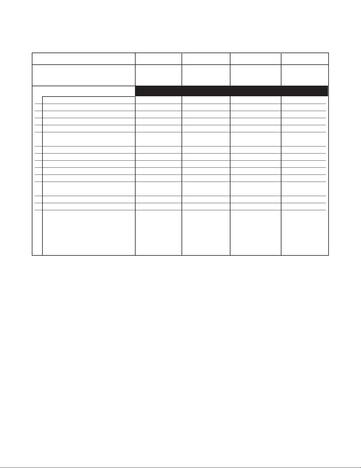
KIT SIZES & CONTENTS
The table and figures below list and illustrates the various K1682 series clutched aluminum drive roll kits for the
various wire sizes. Included with each KP1682 series kit are the components needed for 2-roll and 4-roll feeders.
Each kit includes the following items:
Drive Roll Kit KP1682-035A KP1682-1.0A KP1682-3/64A KP1682-1/16A
Metric Wire Size 0.9 mm 1.0 mm 1.2 mm 1.6 mm
English Wire Size .035 in .040 in 3/64 in (.047) 1/16 in (.063)
Included Items
1 Clutch Bolt S24474 S24474 S24474 S24474
2 Spring T11862-59 T11862-59 T11862-59 T11862-59
3 Clutch Pad (Qty. 2) S24475 S24475 S24475 S24475
4 Drive Roll S24480-035A S24480-1.0A S24480-3/64A S24480-1/16A
5 Outgoing Guide Tube S24479-035A S24479-3/64A S24479-3/64A S24479-1/16A
The following items are to be used for 2-roll operation only:
6 Incoming Guide Tube S21273-3/64 S21273-3/64 S21273-3/64 S21273-1/16
7 Idle Roll Arm Assembly S16666-035A S16666-1.0A S16666-3/64A S16666-1/16A
8 Quick Release Arm M19287 M19287 M19287 M19287
9 Latch S24299 S24299 S24299 S24299
10 Torsion Spring S24300 S24300 S24300 S24300
11 Speed Clip T10982-7 T10982-7 T10982-7 T10982-7
The following items are to be used for 4-roll operation only:
12 Incoming Guide Tube S21273-3/64F S21273-3/64F S21273-3/64F S21273-1/16F
13 Idle Roll and Shaft Assembly S24472-035A S24472-1.0A S24472-3/64A S24472-1/16A
14 Middle Guide Tube M17509-3/64 M17509-3/64 M17509-3/64 M17509-1/16
KP1682 CLUTCHED ALUMINUM DRIVE ROLL KITS
2
Page 3

INSTALLATION INSTRUCTIONS
Bolt
Drive Roll
Top
Clutch
Pad
Bottom
Clutch
Pad
Spring
(2-ROLL FEEDERS)
WARNING
ELECTRIC SHOCK Can Kill
• Only qualified persons should perform
this installation.
• When inching the electrode, the drive mechanism
and the electrode may be electrically "hot".
6. Remove the idle roll arm assembly by removing the
retainer. Store for possible reuse. (See Figure 2).
• The electrode cable that feeds the LN-25 may be
electrically "hot" even when the system is not being
used. Be sure to turn off the welding power source
before changing drive rolls or guides.
• Cabinet feeders like the LN-25 are recommended to
protect the wire from airborne dust. Dirt that accumulates on the wire can be forced into the feeder and
welding gun creating feeding resistance. Maintaining
a clean feeder and a clean wire supply will minimize
feeding problems.
------------------------------------------------------------------------
1. Turn off input power to the welding power source
using the disconnect switch at the fuse box before
installing the clutch drive system.
2. Remove the gun and cable, drive roll, and guide
tubes from the feeder.
3. Remove the hex head screw, clamping collar, and
key from the drive shaft. Save these parts as they
will be required if this feeder is used for normal
operation.
Figure 2
Note: All the parts that were removed from the feeder
should be saved. These parts are required for
normal operation. Now the system is ready to
install all parts of the clutched drive roll system.
7. As shown in Figure 3, install the bottom clutch pad,
the drive roll, the top clutch pad, and the spring &
bolt to the feeder’s drive shaft. DO NOT OVERTIGHTEN THE BOLT. Only snug it to secure the
assembly. The proper tension is preset for the wire
size and does not need adjustment. Make sure that
the clutch material faces the drive roll.
4. Clean and polish the feeder’s drive shaft using a
fine abrasive cloth (400 grit). The drive roll must be
able to spin freely.
5. Remove the pressure arm by removing the hex
head bolt from the gearbox. The bolt, pivot tube,
and thin spacer will be required for the new tension
arm. Remove these parts from the original tension
arm. (See Figure 1).
Figure 1
KP1682 CLUTCHED ALUMINUM DRIVE ROLL KITS
Figure 3
8. Install the short incoming guide tube and outgoing
guide tube into their respective locations. Do not
overtighten the thumb screws as they may damage
the guide tubes.
9. Install the new idle roll assembly on the hinge pin.
A retainer can be used but is not necessary.
10. Assemble the new quick release pressure arm to
the gearbox using the bolt, pivot tube, and washer
removed in Step 5. The idle roll tension is preset
for optimum feeding of aluminum wires. No
adjustment is necessary.
11. Install a new Magnum gun and cable with a fresh
liner designed specifically for aluminum. Page 5
contains recommended liners and tips for standard Magnum guns.
12. Be certain that the guide tubes do not touch the
drive roll or idle roll. If they do touch, readjust
them and tighten in place.
3
Page 4

INSTALLATION INSTRUCTIONS
Bolt
Drive Roll
Top
Clutch
Pad
Bottom
Clutch
Pad
Spring
(4-ROLL FEEDERS)
WARNING
ELECTRIC SHOCK Can Kill
• Only qualified persons should perform
this installation.
• When inching the electrode, the drive mechanism
and the electrode may be electrically "hot".
• Dirt that accumulates on the wire can be forced into
the feeder and welding gun creating feeding resistance. Maintaining a clean feeder and a clean wire
supply will minimize feeding problems.
------------------------------------------------------------------------
6. As shown in Figure 5, mount the bottom clutch pad,
the drive roll, the top clutch pad, and the spring/bolt
assembly to the feeder’s outgoing side drive shaft.
DO NOT OVERTIGHTEN THE BOLT. Only snug it
to secure the assembly. The proper tension is preset for the wire size and does not need adjustment.
Make sure that the clutch material faces the drive
roll.
1. Turn off input power to the welding power source
using the disconnect switch at the fuse box before
installing the clutch drive system.
2. Remove the gun and cable, drive rolls, and guide
tubes from the feeder.
3. Remove the hex head screw, clamping collar, and
key from the drive shafts. Save these parts as they
will be required if this feeder is used for normal
operation.
4. Clean and polish the drive shaft on the outgoing
side of the gearbox using a fine abrasive cloth (400
grit). The drive roll must be able to spin freely.
5. Remove both idle rolls from the swing arms by
removing the pins and the socket head cap screws
and washers on the top and bottom of the swing
arms. Save the pins and hardware for later reuse.
(See Figure 4).
Figure 5
7. Mount the long incoming guide tube and the outgoing guide tube into their respective mounts. Do not
overtighten the thumb screw as it may damage the
guide tubes.
Install the grooved idle roll in the outgoing side
8.
swing arm using the pins and hardware from Step 5.
9. Mount a new Magnum gun and cable with a fresh
liner designed specifically for aluminum. Page 5
contains recommended liners and tips for standard
Magnum guns.
10. Be certain that the guide tube do not touch the
drive roll or the idle roll. If they do touch, readjust
them and tighten in place.
Figure 4
Note: All the parts that were removed from the feeder
should be saved. These parts are required for
normal operation. Now the system is ready to
mount all parts of the clutched drive roll system.
KP1682 CLUTCHED ALUMINUM DRIVE ROLL KITS
4
Page 5

RECOMMENDED GUNS, LINERS and TIPS
The following are the various Magnum guns recommended for feeding aluminum when the appropriate
liners and contact tips are installed .
MAGNUM 450WC WATER COOLED GUN
MAGNUM 300, MAGNUM 300FM, MAGNUM 400,
MAGNUM 400FM, MAGNUM 400DSFM GUNS
Aluminum Liners for 10 ft (3.0 meter) guns:
KP1958-1 (.030-.035 in, .8mm-.9mm) Black
KP1958-5 (.035-3/64 in, .9mm-1.2mm) Blue
KP1958-3 (1/16 in, 1.6mm) Red
Complete guns set up for aluminum feeding:
K684-7 10 ft (3.0 meter) length, .035-3/64 (.9mm -
1.2mm) wire
K684-8 10 ft (3.0 meter) length, 1/16in (1.6 mm)
wire
Aluminum Liners for 10 ft (3.0 meter) guns:
KP1958-1 (.030-.035 in, .8mm-.9mm) Black
KP1958-5 (.035-3/64 in, .9mm-1.2mm) Blue
KP1958-3 (1/16 in, 1.6mm) Red
Aluminum Liners for 15 ft (4.5 meter) and shorter
guns:
KP1958-2 (.030-.035 in, .8mm-.9mm) Black
KP1958-6 (.035-3/64 in, .9mm-1.2mm) Blue
KP1958-4 (1/16 in, 1.6mm) Red
Aluminum Contact Tips:
KP2067-1B1 (.035 in, .9 mm)
KP2067-3B1 (.040 in, 1.0 mm)
KP2067-9B1 (3/64 in, 1.2 mm)
KP2067-7B1 (1/16 in, 1.6 mm)
Note: KP1955-1 and -2 liners can be used, but the
KP1958 series is recommended.
Aluminum Liners for 15 ft (4.5 meter) and shorter
guns:
KP1958-2 (.030-.035 in, .8mm-.9mm) Black
KP1958-6 (.035-3/64 in, .9mm-1.2mm) Blue
KP1958-4 (1/16 in, 1.6mm) Red
Note: KP1955-1 and -2 liners can be used, but the
M18732 series is recommended.
Aluminum Contact Tips:
KP2010-4B1 (.035 in, .9 mm) Notched
KP2010-5B1 (3/64 in, 1.2 mm) Notched
KP2020-9B1 (3/64 in, 1.2 mm)
KP2021-7B1 (3/64 in, 1.2 mm) Heavy Duty
KP2021-8B1 (1/16 in, 1.6 mm) Heavy Duty
MAGNUM 200 AND MAGNUM 200FM GUNS
Aluminum Liners:
KP1955-1 (.035-3/64, .9mm-1.2mm)
Aluminum Contact Tips:
KP2010-4B1 (.035 in, .9 mm) Notched
KP2010-5B1 (3/64 in, 1.2 mm) Notched
KP2020-9B1 (3/64 in, 1.2 mm)
KP2021-7B1 (3/64 in, 1.2 mm) Heavy Duty
KP1682 SERIES ALUMINUM DRIVE ROLL KIT
5
Page 6

• World's Leader in Welding and Cutting Products •
• Sales and Service through Subsidiaries and Distributors Worldwide •
Cleveland, Ohio 44117-1199 U.S.A. TEL: 216.481.8100 FAX: 216.486.1751 WEB SITE: www.lincolnelectric.com
 Loading...