

Page 1

Power Feed 11 SemiAutomatic
RETURN TO MAIN MENU
For use with: Power Feed 11 K1635-1 (World Model) Code 10529; 10777
Power Feed 11 K1636-1 (European Model) Code 10531; 10778
Safety Depends on You
Lincoln arc welding and cutting
equipment is designed and built
with safety in mind. However, your
overall safety can be increased by
proper installation ... and thoughtful operation on your part.
NOT INSTALL, OPERATE OR
REPAIR THIS EQUIPMENT
WITHOUT READING THIS
MANUAL AND THE SAFETY
PRECAUTIONS CONTAINED
THROUGHOUT.
importantly, think before you act
and be careful.
And, most
DO
Cabinet Wire Feeder
IM613-B
October, 2000
Date of Purchase:
Serial Number:
Code Number:
Model:
Where Purchased:
OPERATOR’S MANUAL
Copyright © 2000 Lincoln Global Inc.
Cleveland, Ohio 44117-1199 U.S.A. TEL: 216.481.8100 FAX: 216.486.1751 WEB SITE: www.lincolnelectric.com
• World's Leader in Welding and Cutting Products •
• Sales and Service through Subsidiaries and Distributors Worldwide •
Page 2

i
SAFETY
i
WARNING
CALIFORNIA PROPOSITION 65 WARNINGS
Diesel engine exhaust and some of its constituents
are known to the State of California to cause cancer, birth defects, and other reproductive harm.
The Above For Diesel Engines
ARC WELDING CAN BE HAZARDOUS. PROTECT YOURSELF AND OTHERS FROM POSSIBLE SERIOUS INJURY OR DEATH.
KEEP CHILDREN AWAY. PACEMAKER WEARERS SHOULD CONSULT WITH THEIR DOCTOR BEFORE OPERATING.
Read and understand the following safety highlights. For additional safety information, it is strongly recommended that you
purchase a copy of “Safety in Welding & Cutting - ANSI Standard Z49.1” from the American Welding Society, P.O. Box
351040, Miami, Florida 33135 or CSA Standard W117.2-1974. A Free copy of “Arc Welding Safety” booklet E205 is available
from the Lincoln Electric Company, 22801 St. Clair Avenue, Cleveland, Ohio 44117-1199.
BE SURE THAT ALL INSTALLATION, OPERATION, MAINTENANCE AND REPAIR PROCEDURES ARE
PERFORMED ONLY BY QUALIFIED INDIVIDUALS.
The engine exhaust from this product contains
chemicals known to the State of California to cause
cancer, birth defects, or other reproductive harm.
The Above For Gasoline Engines
FOR ENGINE
powered equipment.
1.a. Turn the engine off before troubleshooting and maintenance
work unless the maintenance work requires it to be running.
____________________________________________________
1.b. Operate engines in open, well-ventilated
areas or vent the engine exhaust fumes
outdoors.
____________________________________________________
1.c. Do not add the fuel near an open flame
welding arc or when the engine is running.
Stop the engine and allow it to cool before
refueling to prevent spilled fuel from vaporizing on contact with hot engine parts and
igniting. Do not spill fuel when filling tank. If
fuel is spilled, wipe it up and do not start
engine until fumes have been eliminated.
____________________________________________________
1.d. Keep all equipment safety guards, covers and devices in
position and in good repair.Keep hands, hair, clothing and
tools away from V-belts, gears, fans and all other moving
parts when starting, operating or repairing equipment.
____________________________________________________
1.e. In some cases it may be necessary to remove safety
guards to perform required maintenance. Remove
guards only when necessary and replace them when the
maintenance requiring their removal is complete.
Always use the greatest care when working near moving
parts.
___________________________________________________
1.f. Do not put your hands near the engine fan.
Do not attempt to override the governor or
idler by pushing on the throttle control rods
while the engine is running.
1.h. To avoid scalding, do not remove the
radiator pressure cap when the engine is
hot.
ELECTRIC AND
MAGNETIC FIELDS
may be dangerous
2.a. Electric current flowing through any conductor causes
localized Electric and Magnetic Fields (EMF). Welding
current creates EMF fields around welding cables and
welding machines
2.b. EMF fields may interfere with some pacemakers, and
welders having a pacemaker should consult their physician
before welding.
2.c. Exposure to EMF fields in welding may have other health
effects which are now not known.
2.d. All welders should use the following procedures in order to
minimize exposure to EMF fields from the welding circuit:
2.d.1.
Route the electrode and work cables together - Secure
them with tape when possible.
2.d.2. Never coil the electrode lead around your body.
2.d.3. Do not place your body between the electrode and
work cables. If the electrode cable is on your right
side, the work cable should also be on your right side.
___________________________________________________
1.g. To prevent accidentally starting gasoline engines while
turning the engine or welding generator during maintenance
work, disconnect the spark plug wires, distributor cap or
magneto wire as appropriate.
2.d.4. Connect the work cable to the workpiece as close as
possible to the area being welded.
2.d.5. Do not work next to welding power source.
Mar ‘95
Page 3
ii
SAFETY
ii
ELECTRIC SHOCK can
kill.
3.a. The electrode and work (or ground) circuits
are electrically “hot” when the welder is on.
Do not touch these “hot” parts with your bare
skin or wet clothing. Wear dry, hole-free
gloves to insulate hands.
3.b. Insulate yourself from work and ground using dry insulation.
Make certain the insulation is large enough to cover your full
area of physical contact with work and ground.
In addition to the normal safety precautions, if welding
must be performed under electrically hazardous
conditions (in damp locations or while wearing wet
clothing; on metal structures such as floors, gratings or
scaffolds; when in cramped positions such as sitting,
kneeling or lying, if there is a high risk of unavoidable or
accidental contact with the workpiece or ground) use
the following equipment:
• Semiautomatic DC Constant Voltage (Wire) Welder.
• DC Manual (Stick) Welder.
• AC Welder with Reduced Voltage Control.
3.c. In semiautomatic or automatic wire welding, the electrode,
electrode reel, welding head, nozzle or semiautomatic
welding gun are also electrically “hot”.
3.d. Always be sure the work cable makes a good electrical
connection with the metal being welded. The connection
should be as close as possible to the area being welded.
3.e. Ground the work or metal to be welded to a good electrical
(earth) ground.
ARC RAYS can burn.
4.a. Use a shield with the proper filter and cover
plates to protect your eyes from sparks and
the rays of the arc when welding or observing
open arc welding. Headshield and filter lens
should conform to ANSI Z87. I standards.
4.b. Use suitable clothing made from durable flame-resistant
material to protect your skin and that of your helpers from
the arc rays.
4.c. Protect other nearby personnel with suitable, non-flammable
screening and/or warn them not to watch the arc nor expose
themselves to the arc rays or to hot spatter or metal.
FUMES AND GASES
can be dangerous.
5.a. Welding may produce fumes and gases
hazardous to health. Avoid breathing these
fumes and gases.When welding, keep
your head out of the fume. Use enough
ventilation and/or exhaust at the arc to keep
fumes and gases away from the breathing zone. When
welding with electrodes which require special
ventilation such as stainless or hard facing (see
instructions on container or MSDS) or on lead or
cadmium plated steel and other metals or coatings
which produce highly toxic fumes, keep exposure as
low as possible and below Threshold Limit Values (TLV)
using local exhaust or mechanical ventilation. In
confined spaces or in some circumstances, outdoors, a
respirator may be required. Additional precautions are
also required when welding on galvanized steel.
3.f.
Maintain the electrode holder, work clamp, welding cable and
welding machine in good, safe operating condition. Replace
damaged insulation.
3.g. Never dip the electrode in water for cooling.
3.h. Never simultaneously touch electrically “hot” parts of
electrode holders connected to two welders because voltage
between the two can be the total of the open circuit voltage
of both welders.
3.i. When working above floor level, use a safety belt to protect
yourself from a fall should you get a shock.
3.j. Also see Items 6.c. and 8.
5.b.
Do not weld in locations near chlorinated hydrocarbon
coming from degreasing, cleaning or spraying operations.
The heat and rays of the arc can react with solvent vapors
form phosgene, a highly toxic gas, and other irritating
products.
5.c. Shielding gases used for arc welding can displace air and
cause injury or death. Always use enough ventilation,
especially in confined areas, to insure breathing air is safe.
5.d. Read and understand the manufacturer’s instructions for this
equipment and the consumables to be used, including the
material safety data sheet (MSDS) and follow your
employer’s safety practices. MSDS forms are available from
your welding distributor or from the manufacturer.
5.e. Also see item 1.b.
Mar ‘95
vapors
to
Page 4

iii
SAFETY
iii
WELDING SPARKS can
cause fire or explosion.
6.a.
Remove fire hazards from the welding area.
If this is not possible, cover them to prevent
the welding sparks from starting a fire.
materials from welding can easily go through small cracks
and openings to adjacent areas. Avoid welding near
hydraulic lines. Have a fire extinguisher readily available.
6.b. Where compressed gases are to be used at the job site,
special precautions should be used to prevent hazardous
situations. Refer to “Safety in Welding and Cutting” (ANSI
Standard Z49.1) and the operating information for the
equipment being used.
6.c. When not welding, make certain no part of the electrode
circuit is touching the work or ground. Accidental contact
can cause overheating and create a fire hazard.
6.d. Do not heat, cut or weld tanks, drums or containers until the
proper steps have been taken to insure that such procedures
will not cause flammable or toxic vapors from substances
inside. They can cause an explosion even
been “cleaned”. For information, purchase “Recommended
Safe Practices for the
Containers and Piping That Have Held Hazardous
Substances”, AWS F4.1 from the American Welding Society
(see address above).
6.e. Vent hollow castings or containers before heating, cutting or
welding. They may explode.
Sparks and spatter are thrown from the welding arc. Wear oil
6.f.
free protective garments such as leather gloves, heavy shirt,
cuffless trousers, high shoes and a cap over your hair. Wear
ear plugs when welding out of position or in confined places.
Always wear safety glasses with side shields when in a
welding area.
6.g. Connect the work cable to the work as close to the welding
area as practical. Work cables connected to the building
framework or other locations away from the welding area
increase the possibility of the welding current passing
through lifting chains, crane cables or other alternate circuits. This can create fire hazards or overheat lifting chains
or cables until they fail.
6.h. Also see item 1.c.
Remember that welding sparks and hot
though
they have
Preparation
for Welding and Cutting of
CYLINDER may explode
if damaged.
7.a. Use only compressed gas cylinders
containing the correct shielding gas for the
process used and properly operating
regulators designed for the gas and
pressure used. All hoses, fittings, etc. should be suitable for
the application and maintained in good condition.
7.b. Always keep cylinders in an upright position securely
chained to an undercarriage or fixed support.
7.c. Cylinders should be located:
• Away from areas where they may be struck or subjected to
physical damage.
• A safe distance from arc welding or cutting operations and
any other source of heat, sparks, or flame.
7.d. Never allow the electrode, electrode holder or any other
electrically “hot” parts to touch a cylinder.
7.e. Keep your head and face away from the cylinder valve outlet
when opening the cylinder valve.
7.f. Valve protection caps should always be in place and hand
tight except when the cylinder is in use or connected for
use.
7.g. Read and follow the instructions on compressed gas
cylinders, associated equipment, and CGA publication P-l,
“Precautions for Safe Handling of Compressed Gases in
Cylinders,” available from the Compressed Gas Association
1235 Jefferson Davis Highway, Arlington, VA 22202.
FOR ELECTRICALLY
powered equipment.
8.a. Turn off input power using the disconnect
switch at the fuse box before working on
the equipment.
8.b. Install equipment in accordance with the U.S. National
Electrical Code, all local codes and the manufacturer’s
recommendations.
8.c. Ground the equipment in accordance with the U.S. National
Electrical Code and the manufacturer’s recommendations.
Mar ‘95
Page 5

iv
SAFETY
iv
PRÉCAUTIONS DE SÛRETÉ
Pour votre propre protection lire et observer toutes les instructions
et les précautions de sûreté specifiques qui parraissent dans ce
manuel aussi bien que les précautions de sûreté générales suiv-
antes:
Sûreté Pour Soudage A L’Arc
1. Protegez-vous contre la secousse électrique:
a. Les circuits à l’électrode et à la piéce sont sous tension
quand la machine à souder est en marche. Eviter toujours
tout contact entre les parties sous tension et la peau nue
ou les vétements mouillés. Porter des gants secs et sans
trous pour isoler les mains.
b. Faire trés attention de bien s’isoler de la masse quand on
soude dans des endroits humides, ou sur un plancher
metallique ou des grilles metalliques, principalement dans
les positions assis ou couché pour lesquelles une grande
partie du corps peut être en contact avec la masse.
c. Maintenir le porte-électrode, la pince de masse, le câble
de soudage et la machine à souder en bon et sûr état
defonctionnement.
d.Ne jamais plonger le porte-électrode dans l’eau pour le
refroidir.
e. Ne jamais toucher simultanément les parties sous tension
des porte-électrodes connectés à deux machines à souder
parce que la tension entre les deux pinces peut être le
total de la tension à vide des deux machines.
f. Si on utilise la machine à souder comme une source de
courant pour soudage semi-automatique, ces precautions
pour le porte-électrode s’applicuent aussi au pistolet de
soudage.
zones où l’on pique le laitier.
6. Eloigner les matériaux inflammables ou les recouvrir afin de
prévenir tout risque d’incendie dû aux étincelles.
7. Quand on ne soude pas, poser la pince à une endroit isolé de
la masse. Un court-circuit accidental peut provoquer un
échauffement et un risque d’incendie.
8. S’assurer que la masse est connectée le plus prés possible
de la zone de travail qu’il est pratique de le faire. Si on place
la masse sur la charpente de la construction ou d’autres
endroits éloignés de la zone de travail, on augmente le risque
de voir passer le courant de soudage par les chaines de levage, câbles de grue, ou autres circuits. Cela peut provoquer
des risques d’incendie ou d’echauffement des chaines et des
câbles jusqu’à ce qu’ils se rompent.
9. Assurer une ventilation suffisante dans la zone de soudage.
Ceci est particuliérement important pour le soudage de tôles
galvanisées plombées, ou cadmiées ou tout autre métal qui
produit des fumeés toxiques.
10. Ne pas souder en présence de vapeurs de chlore provenant
d’opé rations de dégraissage, nettoyage ou pistolage. La
chaleur ou les rayons de l’arc peuvent réagir avec les vapeurs
du solvant pour produire du phosgéne (gas fortement toxique)
ou autres produits irritants.
11. Pour obtenir de plus amples renseignements sur la sûreté,
voir le code “Code for safety in welding and cutting” CSA
Standard W 117.2-1974.
2. Dans le cas de travail au dessus du niveau du sol, se protéger
contre les chutes dans le cas ou on recoit un choc. Ne jamais
enrouler le câble-électrode autour de n’importe quelle partie
du corps.
3. Un coup d’arc peut être plus sévère qu’un coup de soliel,
donc:
a. Utiliser un bon masque avec un verre filtrant approprié
ainsi qu’un verre blanc afin de se protéger les yeux du rayonnement de l’arc et des projections quand on soude ou
quand on regarde l’arc.
b. Porter des vêtements convenables afin de protéger la
peau de soudeur et des aides contre le rayonnement de
l‘arc.
c. Protéger l’autre personnel travaillant à proximité au
soudage à l’aide d’écrans appropriés et non-inflammables.
4. Des gouttes de laitier en fusion sont émises de l’arc de
soudage. Se protéger avec des vêtements de protection libres
de l’huile, tels que les gants en cuir, chemise épaisse, pantalons sans revers, et chaussures montantes.
5. Toujours porter des lunettes de sécurité dans la zone de
soudage. Utiliser des lunettes avec écrans lateraux dans les
PRÉCAUTIONS DE SÛRETÉ POUR
LES MACHINES À SOUDER À
TRANSFORMATEUR ET À
REDRESSEUR
1. Relier à la terre le chassis du poste conformement au code de
l’électricité et aux recommendations du fabricant. Le dispositif
de montage ou la piece à souder doit être branchéà une
bonne mise à la terre.
2. Autant que possible, I’installation et l’entretien du poste seront
effectués par un électricien qualifié.
3. Avant de faires des travaux à l’interieur de poste, la debrancher à l’interrupteur à la boite de fusibles.
4. Garder tous les couvercles et dispositifs de sûretéà leur
place.
Mar. ‘93
Page 6
Thank You
vv
for selecting a QUALITY product by Lincoln Electric. We want you
to take pride in operating this Lincoln Electric Company product
••• as much pride as we have in bringing this product to you!
Please Examine Carton and Equipment For Damage Immediatel
When this equipment is shipped, title passes to the purchaser upon receipt by the carrier. Consequently, Claims
for material damaged in shipment must be made by the purchaser against the transportation company at the
time the shipment is received.
Please record your equipment identification information below for future reference. This information can be
found on your machine nameplate.
Model Name & Number _____________________________________
Code & Serial Number _____________________________________
Date of Purchase _____________________________________
Whenever you request replacement parts for or information on this equipment always supply the information
you have recorded above.
Read this Operators Manual completely before attempting to use this equipment. Save this manual and keep it
handy for quick reference. Pay particular attention to the safety instructions we have provided for your protection.
The level of seriousness to be applied to each is explained below:
y
WARNING
This statement appears where the information must be followed exactly to avoid serious personal injury or
loss of life.
CAUTION
This statement appears where the information must be followed to avoid minor personal injury or damage to
this equipment.
Page 7

TABLE OF CONTENTS
Page
Installation .......................................................................................................Section A
Technical Specifications.......................................................................................................A-1
Safety Precautions ...............................................................................................................A-2
Wire Feeder to Power Source Configurations......................................................................A-2
Mounting on Top of the Power Source..........................................................................A-2
Hanging.........................................................................................................................A-2
On the Floor ..................................................................................................................A-2
Control Box Orientation.................................................................................................A-2
Cable Connections ...............................................................................................................A-3
Control Cable Connections ...........................................................................................A-3
Control Cable Specifications .........................................................................................A-3
Typical Cabinet Feeder Connection..............................................................................A-3
Control Cable Installation ..............................................................................................A-3
Electrode Cable Connections........................................................................................A-3
Electrode Cable Installation ..........................................................................................A-3
Work Cable Connections ..............................................................................................A-4
Wire Drive Gear Ratio (High or Low Speed) ........................................................................A-4
Selecting the Proper Gear Ratio ...................................................................................A-4
Changing the Wire Drive Ratio......................................................................................A-4
DIP Switch Setup .................................................................................................................A-6
Setting DIP Switches in the Control Box .......................................................................A-6
Setting DIP Switches in the Wire Drive .........................................................................A-7
Wire Feed Drive Roll Kits .....................................................................................................A-8
Procedure to Install Drive Rolls and Wire Guides ................................................................A-8
Gun and Cable Assemblies..................................................................................................A-9
Gun Connection Guidelines .................................................................................................A-9
GMAW Shielding Gas ........................................................................................................A-10
Lifting Handle .....................................................................................................................A-10
Optional Features Installation.............................................................................................A-11
Optional Panels for Control Box .........................................................................................A-11
General Panel Installation Guidelines ................................................................................A-11
vi
Operation ............................................................................................................Section B
Safety Precautions ..............................................................................................................B-1
Product Description ..............................................................................................................B-1
Recommended Processes and Equipment ..........................................................................B-1
Duty Cycle ............................................................................................................................B-1
Control Box Operation..........................................................................................................B-1
Control Box Panels - Upper Panel ................................................................................B-1
Control Box Panels - Set Up Controls Description........................................................B-4
Control Box - P.C. Board Adjustments..........................................................................B-4
Control Box - Setting Operating Limits..........................................................................B-5
Control Box - Using Operating Limits............................................................................B-5
Wire Drive Operation............................................................................................................B-6
Wire Drive Settings - External ..............................................................................................B-6
Wire Drive - P.C. Board Adjustments ...................................................................................B-7
Wire Reel Loading................................................................................................................B-7
Feeding Electrode and Brake Adjustment............................................................................B-8
Drive Roll Pressure Setting ..................................................................................................B-8
Gas Guard Regulator Setting ...............................................................................................B-8
Making a Weld......................................................................................................................B-9
Wire Reel Changing .............................................................................................................B-9
Wire Feed Overload Protection ............................................................................................B-9
Component Status Lights ...................................................................................................B-10
Status Light States ......................................................................................................B-10
Accessories .....................................................................................................Section C
Drive Roll and Guide Tube Kits............................................................................................C-1
Other Accessories................................................................................................................C-2
Maintenance ....................................................................................................Section D
Safety Precautions ...............................................................................................................D-1
Routine Maintenance ...........................................................................................................D-1
Avoiding Wire Feeding Problems.........................................................................................D-1
Periodic Maintenance...........................................................................................................D-1
Procedure for Removing Feedplate from Wire Feeder ........................................................D-1
Page 8

vii
TABLE OF CONTENTS
Page
Troubleshooting ..............................................................................................Section E
Safety Precautions ...............................................................................................................E-1
Troubleshooting Guide .........................................................................................................E-2
Diagrams .............................................................................................................Section F
Wiring (Power Feed 11 Wire Feeder) ....................................................................F-1
Wiring (Power Feed 11 Control Box) .....................................................................F-2
Dimension Print......................................................................................................F-3
Parts Lists .......................................................................................................P315 Series
Page 9
A-1
INSTALLATION
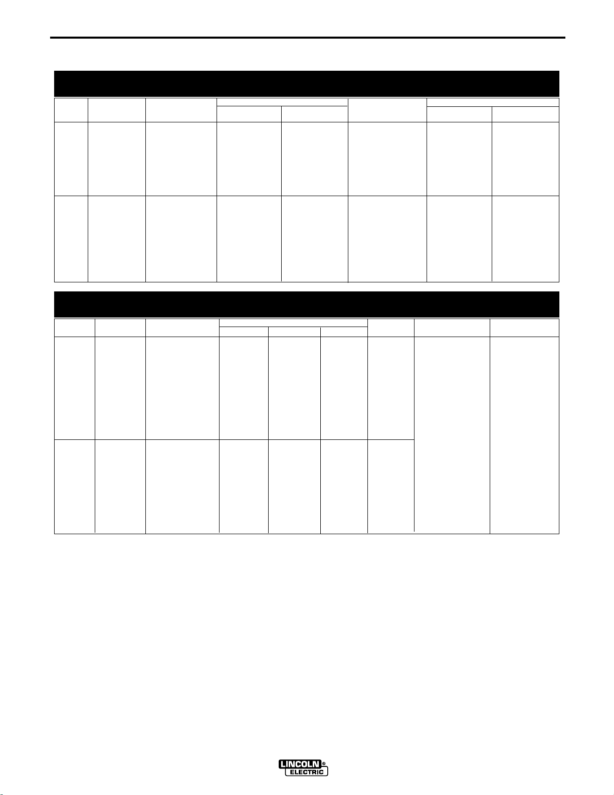
TECHNICAL SPECIFICATIONS – Power Feed 11
COMPLETE UNITS
SPEC.# TYPE LOW SPEED RATIO HIGH SPEED RATIO
Speed Solid Cored Speed Solid Cored
Wire Size Wire Size
A-1
K1635-1
K1636-1
Power Feed 11
Cabinet (1.27-15.9 m/m) (0.6 - 1.6 mm) (0.8 - 2.0 mm) (2.03 - 27.9 m/m) (0.6 - 1.2 mm) (0.8 - 1.2 mm)
Wire
Feeder
(World Model)
Power Feed 11
Cabinet (1.27-15.9 m/m) (0.6 - 1.6 mm) (0.9 - 2.0 mm) (2.03 - 27.9 m/m) (0.6 - 1.2 mm) (0.9 - 1.2 mm)
Wire
Feeder
(European
Model)
50-625 IPM .025 - 1/16 in. .030 - 5/64 in 75 - 1100 IPM .025 - .045 in. .030 - .045 in.
50-625 IPM .025 - 1/16 in. .035 - 5/64 in 75 - 1100 IPM .025 - .045 in. .035 - .045 in.
COMPLETE UNITS
SPEC.# TYPE INPUT POWER PHYSICAL SIZE• TEMPERATURE RATING
K1635-1 Power 40 VDC 20.0 “ 9.0 “ 28.7 “ 61 Lbs
Height Width Depth Weight Operating Storage
Feed 11 (508 mm) ( 230 mm) (729 mm) (27.7 Kg)
(World
Model)
Dimensions
+40°C +40°C
K1636-1 Power 40 VDC 20.0 “ 9.0 “ 28.7 “ 61 Lbs -20°C -40°C
Feed 11 (508 mm) ( 230 mm) (729 mm) (27.7 Kg)
(European
Model)
to to
The PF-11 is environmentally rated IP21S per IEC60529
POWER FEED 11
Page 10

A-2
INSTALLATION
A-2
SAFETY PRECAUTION
ELECTRIC SHOCK can
kill.
• Only qualified personnel should perform this installation.
• Turn off the input power to the power source at the
disconnect switch or fuse box before working on
this equipment. Turn off the input power to any
other equipment connected to the welding system
at the disconnect switch or fuse box before working on this equipment.
• Do not touch electrically hot parts.
• Always connect the Power Wave grounding lug
(located inside the reconnect input access door) to
a proper safety (Earth) ground.
----------------------------------------------------------------------------------------
WIRE FEEDER TO POWER SOURCE
CONFIGURATIONS
The Wire Feeder is equipped to operate in the vertical
or horizontal position. It is shipped ready for use in the
in the vertical position.
MOUNTING ON TOP OF THE POWER SOURCE
The Wire Feeder is shipped with the vertical mounting
bracket installed on the bottom of the Feeder. The
Feeder must be placed on top (right side) of the
Power Source such that the bolt on the mounting
bracket goes thru the hole in the Power Source’s Lift
Bail and the front hole on the right front foot of the
mounting bracket is placed over the weld stud on the
roof of the Power Source. Use the Wing Nut/washer
assembly provided to secure the Feeder to the Power
Source.
Note: A longer or additional Control Cable may be
required when hanging the Feeder. See ACCESSORIES section for information on optional Control
Cables.
ON THE FLOOR
The Wire Feeder is equipped with aluminum skids
which protect the enclosure when the Feeder is
placed on the floor in either the horizontal or vertical
position.
CONTROL BOX ORIENTATION
The Control Box is designed to be easily rotated to
accommodate horizontal or vertical positions. The procedure to change the Control Box Orientation is as follows:
1. Open the Wire Drive compartment door.
2. Locate the Retaining Collar(just above the Wire
Drive unit) and depress the Release Bar and
remove the Retaining Collar from the Control Box
mounting shaft.
3. Pull the Control Box out just enough to allow the
Control Box to be rotated to the desired position
and then re-install. ( Be sure no leads are pinched)
Note: For the Horizontal position the right side of
the Control Box must be next to the front panel
components.
4. Re-install the Retaining Collar. Some light pressure
on the Control Box may be necessary to get the
release bar to “click” into the mounting shaft
groove.
Note: The Wire Feeder can also be mounted horizontally. See ACCESSORIES section for information on
the Optional Horizontal Mounting Bracket.
HANGING
The Wire Feeder is equipped with 2 insulated Lifting
Eyes for hanging the Feeder. It is recommended that
the Lifting Eyes always be used when hanging the
Feeder. The Lifting Handles should be used for short
term carrying of the Feeder
POWER FEED 11
Page 11

A-3
INSTALLATION
A-3
CABLE CONNECTIONS
CONTROL CABLE CONNECTIONS
• All system control cables are the same.
• All control cables can be connected end to end to
extend their length.
• All system equipment must be connected to a control cable.
Welding systems using the Power Feed 11 offer previously unprecedented flexibility in the connection of
system components. This system uses the same type
of control cable between each of the system components. Connections can be “daisy chained” from one
system component to another. Since communication
over the control cables is done by a robust communications network, the order of connection of the components makes no difference. The cables can be connected anywhere that there is a mating connector.
CONTROL CABLE SPECIFICATIONS
aligning the pins and key, plug it into the back of
the wire feeder head, rotate the threaded locking
ring until the connector is completely fastened
Note: Depending on the location of the of the Wire
Feeder relative to the Power Source a longer
Control Cable or additional Control Cable(s) may be
required.See section 2.0 “Optional Features” for
information on optional Control Cables.
ELECTRODE CABLE CONNECTIONS
Most welding applications run with the electrode being
positive (+). For those applications, connect the electrode cable between the wire feeder and the positive
(+) output stud on the power source (located beneath
the spring loaded output cover near the bottom of the
case front).
A work lead must be run from the negative (-) power
source output stud to the work piece. The work piece
connection must be firm and secure, especially if
pulse welding is planned. Excessive voltage drops at
the work piece connection often result in unsatisfactory pulse welding performance.
The cable is a 5 copper conductor cable in a SO-type
rubber jacket. There is one 20 gauge twisted pair for
network communications. This pair has an impedance
of approximately 120 ohms and a propagation delay
per foot of < 2.1 ns. There are two 12 gauge conductors that are used to supply the 40 VDC to the network. The fifth wire is 18 gauge and is used as an
electrode sense lead. It is typically connected to the
feed plate on the feed head when that feed head is
active.
NOTE: Maximum cable length between any two
nodes is 250'.
TYPICAL CABINET FEEDER CONNECTION
The Control cable is connected from the Power
Source to the Wire Feeder. The Power Feed 11
comes standard with an 8 ft. Control Cable.
CONTROL CABLE INSTALLATION:
1. Connect the end of the control cable with the 5-pin
cable plug to the mating receptacle on the power
source. With the pins and key aligned, plug it into
the power source, rotate the threaded locking ring
until the connector is completely fastened
When negative electrode polarity is required, such as
in some Innershield™ applications, install as above,
except reverse the output connections at the power
source (electrode cable to the negative (-) stud, and
work cable to the positive (+) stud).
ELECTRODE CABLE INSTALLATION:
The Power Feed 11 comes with an installed electrode
cable. Connect the power source end of the cable to
the power source output terminal of the desired polarity.
The K1636-1 Power Feed 11 (Europe) electrode cable
is equipped with a Twist-Mate™ connector while the
K1635-1 Power Feed 11 (World) is equipped with a
lug connector. Also for both models open the Wire
Drive compartment door and check that the electrode
cable lug is against the Feedplate and that the connection is tight. Any electrode cable replacement or
extension should be sized according to the specifications given in the work cable connections section .
2. Connect the end of control cable with the 5-socket
end to the mating receptacle on the back of the
wire feeder. To connect the cable to the feeder,
POWER FEED 11
Page 12
A-4
INSTALLATION
A-4
WORK CABLE CONNECTIONS
Connect a work lead of sufficient size and length (per
the following table) between the proper output terminal on the power source and the work. Be sure the
connection to the work makes tight metal-to-metal
electrical contact.
To avoid interference problems with other equipment
and to achieve the best possible operation, route all
cables directly to the work or wire feeder. Avoid
excessive lengths, bundle the electrode and ground
cables together where practical, and do not coil
excess cable.
Minimum work and electrode cables sizes are as follows:
Current
60% Duty
Cycle
500 Amps
600 Amps
Minimum Copper Work Cable Size, AWG
Up to 100 ft Length (30m)
3/0 (85 mm2)
3/0 (85 mm2)
SELECTING THE PROPER GEAR RATIO
See the Technical Specifications at the front of this
section for feed speed and wire size capabilities with
high and low speed gear ratios. To determine whether
you should be using the high or low speed ratio use
the following guidelines:
- When operating at wire feed speeds
(15.9 m/m), you must have the high speed gear
(large 30 tooth, 1.6 inch diameter gear) installed.
- When operating at wire feed speeds below 625 IPM
(15.9 m/m), you must have the low speed gear
(small 17 tooth, .95 inch diameter gear) installed for
all wire sizes because using the low speed ratio provides the maximum available wire feeding force.
Note:
If you are feeding only .045” (1.2 mm) diameter and smaller wires you may, at your option, use
the factory installed high speed ratio.
above 625 IPM
CHANGING THE WIRE DRIVE RATIO
When using an inverter type power source, Use the
largest welding (electrode and ground) cables that are
practical. At least 3/0 (85 mm
the average output current would not normally require
it. When pulsing, the pulse current can reach very
high levels. Voltage drops can become excessive,
leading to poor welding characteristics, if undersized
welding cables are used.
2
) copper wire — even if
WIRE DRIVE GEAR RATIO (HIGH
OR LOW SPEED)
The speed range capability and drive torque of the
Power Feed 11 wire drive can be easily and quickly
changed by changing the external drive gear. The
Power Feed 11 is shipped with both a high speed and
a low speed gear. As shipped from the factory, the
high speed (low torque) gear is installed on the feeder. If this is the desired gear ratio, no changes need
to be made.
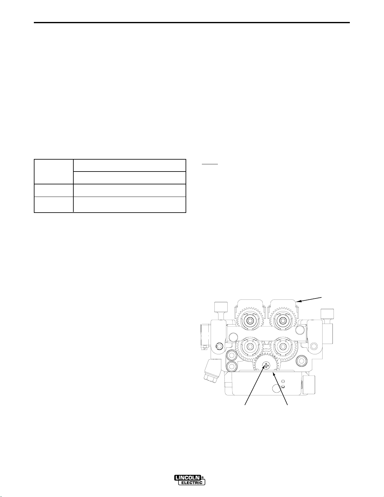
Changing the ratio requires a gear change and a PC
board switch change. The Power Feed 11 is shipped
with both a high speed and a low speed gear. As
shipped from the factory, the high speed (low torque)
gear is installed on the feeder. For identification purposes, the low speed (high torque) gear has 17 teeth
and is .95 inches in diameter. The high speed gear
has 30 teeth and is 1.6 inches in diameter. See
Figure A.2.
WIRE
FEEDER
FIGURE A.2 — CHANGING WIRE DRIVE RATIO.
POWER FEED 11
PHILLIPS
HEAD SCREW
DRIVE
GEAR
Page 13

A-5
INSTALLATION
A-5
RATIO CHANGE PROCEDURE:
1) Power down the Power Feed by turning OFF its
companion PowerWave power source. For maximum safety, disconnect the control cable from the
Power Feed.
2) Pull open the Wire Feeder’s Compartment Door.
3) Remove the Feedplate per the following:
a) Disconnected the Electrode from the Feedplate
b) Pull open the Wire Drive Pressure Door.
c) Using a 3/16" Hex Key Wrench remove the two
screws that secure the Feedplate to the
Interface Plate. These screws are located just
below and to the right and just below and to left
of the lower drive gears.
d) Swing the rear of the Feedplate out towards
the front of the machine which will allow it to be
pulled back and out of the machine.
Note: The shielding gas hose and gun leads are still
attached to the Feedplate. This is OK provided that
the Feedplate is setting on a suitable surface such
that no excess tension is being place on the gas hose
and gun leads. If necessary remove the gas hose and
disconnect the leads.
4) Remove the pinion gear as follows:
a) Using a phillips head screwdriver remove the
screw that secures the gear to the output shaft
of the gearbox and remove the gear.
b) Lightly cover the output shaft with engine oil or
equivalent. Install appropriate size gear(small
gear for low speed and a large gear for high
speed) onto output shaft and secure with flat
washer, lock washer, and Phillips head screw
which were previously removed.
Note: Be sure that the woodruff key remains secured
to the output shaft during the gear change.
6) Re-attach Feedplate (and gas hose and gun leads
if they were removed) that was removed in Step 3
and reconnect the Electrode Cable.
Note: The screws that secure the Feedplate to the
Interface Plate must go thru the insulator bushings in
the Feedplate.
7) Close the Wire Drive Pressure Door and Wire
Feeder’s Compartment Door.
8) Set the High/Low Dip Switch on Feed Head PC
board as follows:
a) Remove the left case side as follows:
- Remove 4 screws that directly secure the
case side
- Loosen the 3 screws that secure the lower
skid rail. This will free the case side edge
and allow it to be lifted up and removed.
Note: PF-11's that have been installed horizontally on
top of the Power Source will need to remove the
Mounting Bracket in order to access the the left case
side.
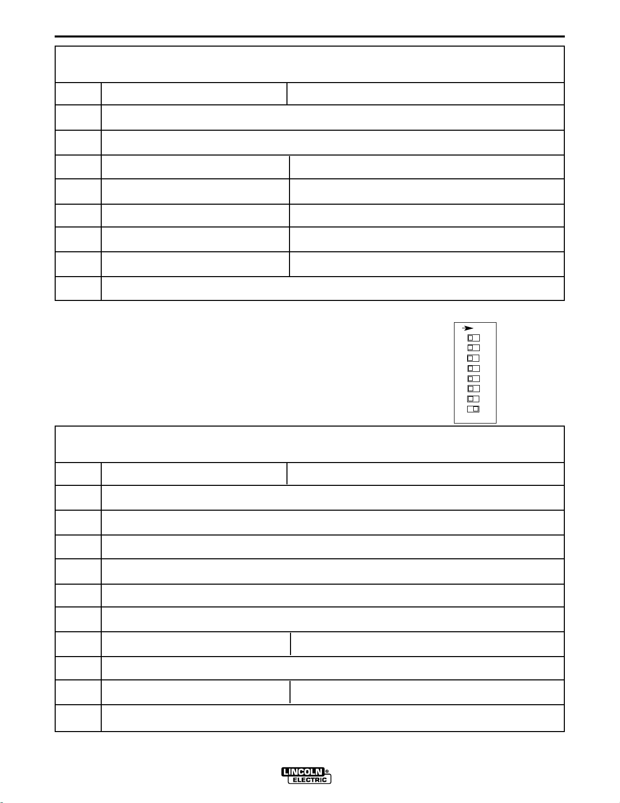
b) Locate the 8-position DIP switch (S1) on the
Feed Head PC board. The setting will be made
on the bottom most switch, DIP switch #8.
c) Using a pencil or other small object, to slide the
switch left, to the “OFF" position, when the low
speed gear is installed. Conversely, slide the
switch right, to the “ON" position, when the high
speed gear is installed. Refer to the diagrams
below.
Setting for Low Speed Setting for High Speed
O
N
12 3456 78
N
O
12 3456 78
5) Position the Motor/Gearbox as follows:
a) There are 4 screws that secure the
Motor/Gearbox to the Interface Plate. Using a
3/16" Hex Key Wrench remove the 2 upper
screws and loosen (but don’t remove) the 2
lower screws.
b) Slide the Motor/Gearbox to the
UPPER SET OF HOLES FOR LOW SPEED
LOWER SET OF HOLES FOR HIGH SPEED.
c) Secure in position with flat washers, lock wash-
ers, and socket head screws that were previously removed and loosened.
S1
d) Replace the left case side and screws(and
POWER FEED 11
S1
Mounting Bracket if required). The PC board
will “read” the switch at power up, automatically
adjusting all control parameters for the speed
range selected.
Page 14

A-6
INSTALLATION
A-6
DIP SWITCH SETUP
ON
12 3456 78
S1
SETTING DIP SWITCHES IN THE
CONTROL BOX
There are two DIP switch banks on the mother board
of the Control Box. They are labeled S1 and S2 and
are located and oriented as shown in Figure A.3.
ON
12 3456 78
FIGURE A.3
S2
S1 DIP Switch Bank on Control Box Motherboard (For Software version S24456-1)
Switch Off On
1 Standard speed limits adjustable High speed gearbox limits adjustable
2 WFS Display = inches/minute WFS Display = meters/minute
3 Left Display is always preset WFS Left Display is preset WFS when weld current is not flowing
Left Display is actual weld current when weld current is flowing
CC modes override this switch regardless of position. Left Display is always preset weld current when weld current is not flowing and actual weld current when weld current is flowing
4 Run-in = Minimum Speed Available Run-in = weld WFS
If any option containing a Run-in setting is connected to the motherboard, it automatically
overrides this switch regardless of position.
5 Memory change with trigger disabled Memory change with trigger enabled
6 Acceleration, MSB (Sets acceleration rate for wire drive) see below
7 Acceleration (Sets acceleration rate for wire drive) see below
8 Acceleration, LSB (Sets acceleration rate for wire drive) see below
DIP SWITCH 6 DIP SWITCH 7 DIP SWITCH 8
Acceleration 1 (slow) Off Off On
Acceleration 2 Off On Off
Acceleration 3 Off On On
Acceleration 4 On Off Off
Acceleration 5 (fast ) (factory setting) Off Off Off
Note: the factory shipped settings for Switch S1 are as follows:
PF-11 European - Switches 1-2 “ON”; Switches 3-8 “OFF”
PF-11 World - Switch 1 “ON”; Switches 2-8 “OFF”
POWER FEED 11
Page 15
A-7
INSTALLATION
S2 DIP Switch Bank on Control Box Motherboard (For software version S24456-1)
Switch Off On
1 Network Group ID, MSB (Assigns Control Box to a specific group) (Off is factory setting)
2 Network Group ID, LSB (Assigns Control Box to a specific group ) (Off is factory setting)
3 4-Step Domestic Configuration 4-Step European Configuration
4 Power Feed 10 / Dual Power Feed 11
5 Procedure change with trigger “OFF” Procedure change with trigger “ON”
6 Must be off for normal operation Adjust lower limits
7 Must be off for normal operation Adjust upper limits
8 Must be on for all units (Permits selection of extended modes)
Note: the factory shipped settings for Switch S2 are as follows:
PF-11 European - Switches 1,2 & 5-7 “OFF”; Switches 3,4,8 “ON”
PF-11 World - Switches 1-3 & 5-7 “OFF”; Switches 4, 8 “ON”
N
O
12 3456 78
A-7
SETTING DIP SWITCHES IN THE WIRE
DRIVE
There is one DIP switch bank on the control board of
the wire drive. It’s labeled S1 and is located and oriented as shown in Figure A.4.
FIGURE A.4
S1
S1 DIP Switch Bank on Wire Drive Control Board (For software version S24468-1)
Switch Off On
1 Network Group ID, MSB (Assigns Wire Drive to a specific group)
2 Network Group ID, LSB (Assigns Wire Drive to a specific group )
3 Network Feed Head ID, MSB (Assigns feed head number to wire drive)
4 Network Feed Head ID (Assigns feed head number to wire drive)
5 Network Feed Head ID, LSB (Assigns feed head number to wire drive)
6 Spare
7 Electrode Sense Polarity = Positive Electrode Sense Polarity = Negative
Switch position must match polarity of weld cable attached to feed plate.
8 Gear Box Ratio = Low Gear Box Ratio = High
Switch position must match actual gear box ratio of wire drive.
Note: the factory shipped settings for Switches 1-7 is “OFF”, Switch 8 is “ON”.
POWER FEED 11
Page 16

A-8
INSTALLATION
A-8
WIRE FEED DRIVE ROLL KITS AND
FAST-MATE™ GUN ADAPTER
GUIDE TUBES
NOTE: The maximum rated solid and cored wire
sizes and selected drive ratios are shown on the
SPECIFICATIONS in the front of this section. The
electrode sizes that can be fed with each drive roll and
wire guide are stenciled on each part. Check the kit
for proper components. Kit specifications can be
found in the ACCESSORIES section.
FAST-MATE™ GUN ADAPTER GUIDE
TUBES
Guide Tubes for Steel Wire:
The Power Feed 11 is supplied with 4 wire guide
tubes which allow the I.D. of the Fast-Mate™ gun
adapter to be optimized for every wire size. The various size wire guide tubes are identified by the number
of rings scribed toward one end of the tube and
should be selected per the table below.
PROCEDURE TO INSTALL DRIVE
ROLLS AND GUIDE TUBES
WARNING
ELECTRIC SHOCK can kill.
• Do not touch electrically live parts such
as output terminals or internal wiring.
When feeding without Power Feed 11 “Cold
•
Feed” feature, electrode and drive mechanism
are “hot” to work and ground and could remain
energized several seconds after the gun trigger
is released.
• Turn OFF input power at welding power
source before installation or changing drive
roll and/or guide tubes.
• Welding power source must be connected
to system ground per the National Electrical
Code or any applicable local codes.
• Only qualified personnel should
perform this installation.
Observe all additional Safety Guidelines detailed
throughout this manual.
DRIVE ROLL KIT AND GUIDE TUBE
INSTALLATION
Wire Size Number
of Rings
.023"-.045" (0.6-1.2mm) 1
.045"-1/16" (1.2-1.6mm) 2
1/16"-5/64" (1.6-2.0mm) 3
5/64"-7/64" (2.0-2.8mm) 4
Guide Tubes for Aluminum Wire:
For optimum aluminum wire feeding the appropriate
plastic lined guide tube should be used per the table
below. These must be ordered.
Part Wire Size Tube
Number Color
S24129-1 .030"-.035" (0.8-0.9mm) Black
S24129-2 .035"-3/64" (0.9-1.2mm) Blue
S24129-3 1/16" (1.6mm) Red
1) Turn OFF Welding Power Source.
2) Pull open Pressure Door to expose rolls and wire
guides.
3) Remove Outer Wire Guide by turning knurled
thumb screws counter-clock-wise to unscrew them
from Feed plate.
4) Remove drive rolls, if any are installed, by pulling
straight off shaft. Remove inner guide.
Note: Not all Drive Roll and Wire Guide changes
require changing the Gun Adapter Guide
Tubes. See FAST-MATE™ GUN ADAPTER
GUIDE TUBES in this section for the proper
size guide tube required for the wire size to be
used. If a guide tube change is NOT required
skip Steps 5 & 6 And go to Step 7.
5) Loosen the small Knurled Knob on the Feedhead.
This the Knurled Knob that is closest to the Gun
Adapter and is used to secure the wire guide tube
into the Gun Adapter.
6) Insert the new wire guide tube (either end, tube is
symmetric) into the incoming end of the Gun
Adapter (This will remove an existing tube if present) until it flush with the incoming end and retighten the small Knurled Knob.
POWER FEED 11
Page 17

A-9
INSTALLATION
A-9
7) Insert inner Wire Guide, groove side out, over the
two locating pins in the feed plate.
8) Install each drive roll by pushing over shaft until it
butts up against locating shoulder on the drive roll
shaft. (Do Not exceed maximum wire size rating of
the wire drive).
9) Install Outer Wire Guide by sliding over locating
pins and tightening in place.
10) Engage upper drive rolls if they are in the “open”
position and close Pressure Door.
NOTE: To set drive roll pressure, see DRIVE ROLL
PRESSURE SETTING in the OPERATION section.
GUN AND CABLE ASSEMBLIES
The Power Feed 11 wire feeder is equipped with a
Fast-Mate™ Gun Adapter that provides for the use of
guns with Fast-Mate™ or European style gun connections and will handle both standard Fast-Mate™and
Dual Schedule Fast-Mate™ guns.
The Fast-Mate™ Gun Adapter requires the use of
wire guide tubes. The Power Feed 11 is supplied with
4 wire guide tubes. See FAST-MATE™ GUN
ADAPTER GUIDE TUBES and DRIVE ROLL KIT
AND GUIDE TUBE INSTALLATION sections for proper selection and installation of Fast-Mate™ Gun
Adapter wire guide tubes.
MAGNUM GUNS
Magnum Fast-Mate™ air cooled and water cooled
gun and cable assemblies are available to allow welding with solid and cored wire electrodes. See the
appropriate Magnum Literature for descriptions of the
200 to 400 ampere air cooled gun and cables that are
available, as well as the Magnum 450 ampere water
cooled gun and cable.
Magnum X-Tractor gun and cable assemblies provide
fume extraction capability for welding with solid and
cored wire electrodes. See the appropriate Magnum
Literature for descriptions of the 250 to 400 ampere
air cooled gun and cable assemblies that are available.
GUN CONNECTION GUIDELINES
General Guidelines
The instructions supplied with the gun should be followed when installing and configuring a gun. What follows are some general guidelines that are not intended to cover all guns.
a. Check that the drive rolls, wire guide and gun
adapter wire guide tube are proper for the electrode size and type being used. If not, change
them.
b. Connect gun to gun connector making sure all pins
and gas tube line up with appropriate holes in connector. Tighten gun by turning large nut on gun
clockwise.
WATER COOLED GUIDELINES
The Power Feed 11 comes equipped with coolant inlet
and outlet connections on the front and back of the
feeder. The maximum water pressure permitted for
use with the PF-11 is 100 psi.
a. Using male quick connect fittings, connect appro-
priate water hoses to the coolant inlet and outlet on
the back of the feeder. Connect the other ends of
these hoses to the appropriate ports on your water
cooling unit.
b. Connect the gun hoses to the coolant inlet and out-
let on the front of the feeder. In the event the
water line fittings on your water cooled gun are
incompatible with the female quick connects on the
front of the Power Feed 11, male quick connects
are provided for installation on 3/16" (5mm) hose
(Customer to provide appropriate clamps). The
feeder connectors self seal when disconnected.
c. Water cooled guns can be damaged very quickly if
they are used even momentarily without water
flowing. To protect the gun, we recommended that
a K1536-1 Magnum Flow Sensor kit be installed.
This will prevent wire feeding if no water flow is
present. See ACCESSORIES Section for more
information regarding this kit
Note:Most Non-Lincoln Guns can be connected to the
Power Feed 11 provided the gun has a European
Style Gun Connector.
POWER FEED 11
Page 18

A-10
INSTALLATION
A-10
GMAW SHIELDING GAS
WARNING
CYLINDER may explode if damaged.
• Keep cylinder upright and chained to
support.
• Keep cylinder away from areas where
it may be damaged.
• Never lift welder with cylinder attached.
• Never allow welding electrode to touch cylinder.
• Keep cylinder away from welding or other live elec-
trical circuits.
BUILDUP OF SHIELDING GAS may
harm health or kill.
• Shut off shielding gas supply when not
in use.
SEE AMERICAN NATIONAL STANDARD Z-49.1,
“SAFETY IN WELDING AND CUTTING” PUBLISHED
BY THE AMERICAN WELDING SOCIETY.
------------------------------------------------------------------------
Customer must provide a cylinder of shielding gas, a
pressure regulator, a flow control valve, and a hose
from the flow valve to the gas inlet fitting of the wire
drive unit.
Any shielding gas can be used that is recommended
in the electrode’s product literature at a maximum
pressure of 60 psi (4.1 bar) This may include such
gasses as Argon, Helium, Nitrogen, and blended
gasses such Ar-He, Ar-N2, Ar-O2, Ar-CO2, CO2, and
Ar-CO2-O2.
LIFTING HANDLE
The Power Feed 11 is shipped with a insulated Lifting
Handle which can be mounted on the top or back of
the Wire Feeder. This handle is intended to be primarily used for short term carrying of the Feeder. While
this handle is suitable for hanging the Feeder it is recommended that the Lifting Eyes also always be used
when hanging the Feeder. The procedure to mount
the Lifting Handle is as follows:
1) Turn Off the Welding Power Source
2) Open the Wire Drive Compartment Door and
remove the wire reel if present.
3) Using the appropriate socket and wrench(1/2")
remove the 2 screws and nuts from either the middle top or middle rear of the Feeder. The screws
are black in color and about 6.5" apart.
4) Using the hardware provided with the handle
secure the handle in the desired position.
Note: If it is desired to have handles in both the top
and back locations, an additional handle can be
ordered. ( Part Number S24131)
Connect a supply hose from the gas cylinder flow
valve outlet to the 5/8-18 female inert gas fitting on the
back panel of the Wire Feeder. See ACCESSORIES
section for information regarding the optional Gas
Guard Regulator
Note: Included with the K1636-1 Power Feed 11
(Euro) ONLY is a barbed fitting and union nut
that can be installed on the 5/8-18 female inert
gas fitting on the back panel of the Wire Feeder
and allows for the connection of a 3/16"(5mm)
I.D. gas hose (Customer to provide appropriate
clamps).
POWER FEED 11
Page 19

A-11
INSTALLATION
A-11
OPTIONAL FEATURES INSTALLATION
A number of Optional Features are available for
use with Power Feed 11. Some Installation information is provided in this section, REFER TO THE
INSTRUCTIONS THAT COME WITH EACH KIT FOR
DETAILED INFORMATION REGARDING INSTALLATION.
OPTIONAL PANELS FOR CONTROL BOX
All optional panels for the control box are described in
the ACCESSORIES section of this manual along with
their installation instructions as are all other pieces of
optional equipment.
The PF-11 Control Box is designed to accept two control panels and one door option. Panels can be
mounted in one of two positions: Upper and lower.
Each Control Box is shipped with a Control/Display
(CD) panel installed in the upper position, and a
CV/Gouge (CV/G) panel in the lower position.
The CD panel must be installed in every Control Box.
The remaining panel can be one of the following:
CV/G, MX2, or MSP2.
GENERAL PANEL INSTALLATION
GUIDELINES:
Installation or removal of any panel can be done with
only a Phillips screwdriver after the system power is
turned off. To remove a panel, remove the two screws
holding it in place, remove the push-on chassis
ground wire and remove the harness connection to
the Control Box main PC board. To install any panel,
reverse that process. Turn power back on when complete (option panels are only recognized at power up.
Do not install panels with the power on.) Note that
removal or installation of any panel may also require
the removal of the other panel, in order to have easy
access to the PC board connectors. Detailed installation instructions are shipped with each option panel.
Note: The CD panel must be installed in the upper
position; its harness is not long enough to allow
installation in the lower position. Similarly,
option panels must be installed in the lower
position.
POWER FEED 11
Page 20

B-1
OPERATION
B-1
SAFETY PRECAUTIONS
WARNING
ELECTRIC SHOCK can kill.
• Do not touch electrically live parts such
as output terminals or internal wiring.
•
When inching with gun trigger, electrode and
drive mechanism are “hot” to work and
ground and could remain energized several
seconds after the gun trigger is released.
• Turn OFF input power at welding power
source before installation or changing
drive roll and/or guide tubes.
• Welding power source must be connected
to system ground per the National
Electrical Code or any applicable local
codes.
• Only qualified personnel should
perform this installation.
Observe all additional Safety Guidelines detailed throughout this manual.
PRODUCT DESCRIPTION
The Power Feed 11 is a high performance, digitally
controlled, modular cabinet style wire feeder.
Properly equipped, it can support the GMAW, GMAWP, FCAW, and SMAW processes. The Power Feed
wire feeders are designed to be a part of a modular,
multi process welding system.
The Power Feed 11 is a 4 driven roll feeder that operates on 40VDC input power.
RECOMMENDED PROCESSES AND
EQUIPMENT
RECOMMENDED PROCESSES
The Power Feed 11 can be set up in a number of configurations. It is designed to be used for GMAW,
GMAW-P, FCAW, and SMAW for a variety of materials, including mild steel, stainless steel, and cored
wires.
RECOMMENDED EQUIPMENT
The Power Feed 11 must be used with power sources
having digital communication capabilities and 40 VDC
auxiliary power. The presently available power source
is the PowerWave 455.
DUTY CYCLE
The Power Feed 11 wire feeder is capable of welding
at a 100% duty cycle (continuous welding). The power
source will be the limiting factor in determining system
duty cycle capability.
CONTROL BOX OPERATION
The most frequently used Control Box controls and
settings are external; some features are accessed by
internal controls and settings.
CONTROL BOX PANELS - UPPER PANEL
The Power Feed wire feeders are designed to be
used with Power Feed compatible power sources,
operating as a system. Each component in the system
has special circuitry to “talk with” the other system
components, so each component (power source, wire
feeder, electrical accessories) knows what the other is
doing at all times. This shared information lays the
groundwork for a system with superior welding performance.
The Power Feed 11 is available configured in both
European and World models. There are two features
that distinguish the European from the World model.
The first is the 4 step trigger logic and the second is
the type of electrode connection which is a Twist-
TM
Mate
later in this section for more details on the 4 step trigger logic.
on the European and a Lug on the World. See
POWER FEED 11
Control/Display Panel: (Required)
Each PF-11 Control box must have a Control/Display
(CD) panel. This panel consists of adjustment knobs,
digital displays and a series of indicator lights (LEDs).
There are two knobs; each has a 4 digit LED display
and a pair of LEDs associated with it. Knobs and displays have dual functions; the LEDs indicate which
function at any given time. This panel also has a dual
color Status LED, used to indicate the general health
status of the Control Box and its connection to other
components in the system (power source, wire drive,
etc.).
The left knob/display is labeled WFS / AMPS (wire
feed speed/amps). In non-synergic modes, the WFS
control changes the wire feed speed according to the
desired procedure. In synergic welding modes (synergic CV, pulse GMAW) WFS is the dominant control
parameter, controlling all other variables.
Page 21

B-2
OPERATION
B-2
The user adjusts WFS according to factors such as weld
size, penetration requirements, heat input, etc. The power
source then uses the WFS setting to adjust its output characteristics (output voltage, output current) according to preprogrammed settings contained in the power source. In
constant current modes (arc gouging, stick, TIG) this control
adjusts the output current, in amps. An LED lights to inform
the user which function (WFS or amps) is active.This display
can be either English or metric units. Further, this display
can be set up to display either WFS or amps when using
wire welding modes. (See SETTING DIP SWITCHES in the
INSTALLATION section.)
The right knob is labeled VOLTS / TRIM. In constant voltage modes (synergic CV, standard CV) the control adjusts
the welding voltage. In pulse synergic welding modes
(pulse GMAW only) the user can change the Trim setting to
adjust the arc length. It is adjustable from 0.50 to 1.50. A
Trim setting of 1.00 means than no adjustments will be
made to the preset arc lengths, and is optimum for most
conditions. An LED lights to inform the user which function
(volts or trim) is active.
Both displays indicate preset values, according to the weld
mode selected, when not welding. Once welding begins,
they switch to displaying actual values. At that time, the
indicator LEDs will flash to signify actual values are being
displayed. The displays hold the actual values for 5 seconds after a weld is stopped. Turning a knob during the
hold time shuts off the hold, and returns the meters to their
preset values.
The allowable settings are determined by other system components. The WFS range, for instance, is dependent upon
the gear range in the Wire Drive and on the welding programs in the Power Wave power source. The voltage and
current are similarly limited by programs in the Power Wave.
Control Box Panels - Lower Panels
A description of the set up controls, Preflow, Run In, Arc
Control, Postflow, and Crater, and their maximum and minimum values, is in Control Box Panels - Set Up Controls
Description in this section.
K1542-4 CV/Gouge Panel:(Std.)
The CV/G Panel has a single toggle switch for selecting
between two weld modes: CV welding and arc gouging. All
other set up parameters, Preflow, Arc Control, Postflow, and
Crater, default to zero or off. Run-in defaults to the minimum value, or to the weld speed depending on the position
of its associated dip switch. (See “Setting DIP Switches in
the Control Box” section.) Burn back defaults to the onboard trimmer adjustment. When used with the Dual
Procedure or Memory options, only the WFS/Amps and
Volts/Trim settings are saved.
POWER FEED 11
Selecting the Gouge mode immediately energizes the
output terminals on the power source. The output current is set by the Amps control. The Volts/Trim adjustment has no effect in this mode.
K1542-11 MX2 Panel:(Optional)
This panel provides a selection of four weld modes:
CV/MIG, CV/Flux Cored, CC/Stick/soft and
CC/Stick/Crisp through a toggle switch and indicator
lights (LEDs). It allows for adjustment of all set up parameters, Preflow, Run In, Arc Control, Burnback,
Postflow, and Crater, through an up/down toggle switch,
indicator lights and a 3 digit display.
Weld modes are selected with the Mode Select switch,
an up/down center-off momentary toggle switch. Moving
the switch bat up or down moves the Weld Mode LED in
the corresponding direction. Holding the switch in either
direction will cause the indicator to move quickly in the
corresponding direction until the switch is released, or
the upper or lower limit is reached.
To adjust Set Up parameters, first select the Set Up
parameter for adjustment, and then adjust the displayed
value up or down.
Set Up parameters are selected with the Select switch,
an up/down center-off momentary toggle switch. Moving
the switch bat up or down moves the Weld Mode LED in
the corresponding direction. Holding the switch in either
direction will cause the indicator to move quickly in the
corresponding direction until the switch is released, or
the upper or lower limit is reached.
The value of the active Set Up parameter, as defined by
the Set Up LED, is displayed on the MX2 panel Set Up
display. The value can be modified with the Set switch.
The Set switch is an up/down center-off momentary toggle switch. Moving the switch bat up or down adjusts the
displayed value in the corresponding direction. Holding
the switch in either direction will cause the display to
move quickly in the corresponding direction until the
switch is released, or the upper or lower parameter limit
is reached.
To energize the output studs in either CC/Stick mode,
the right Control/Display panel knob, labeled Volts/Trim,
must be used. The Volts/Trim knob must be turned
clockwise roughly a quarter revolution to energize the
output studs. (The Volts/trim display will indicate ‘On’
when the studs are energized.) Similarly, turning the
knob a quarter turn counter-clockwise de-energizes the
output studs. If a CC/Stick weld mode is entered through
use of the Dual Procedure, the studs will be in the same
state as when they were last used. If a CC/Stick weld
mode is entered through a Memory recall, the studs will
be de-energized.
Page 22

B-3
OPERATION
B-3
K1542-12 MSP2 Panel: (Optional)
This panel provides a selection of over 25 weld
modes, including CV, pulse, FCAW and CC, through
a toggle switch and indicator lights (LEDs). It allows
for adjustment of all set up parameters, Preflow, Run
In, Arc Control, Burnback, Postflow, and Crater,
through an up/down toggle switch, indicator lights and
a 3 digit display.
To adjust a set up parameter (Weld Mode being one
of those parameters), first select one of the set up
parameters for adjustment, and then adjust the displayed value up or down.
Set up parameters are selected with the Select switch,
an up/down center-off momentary toggle switch.
Moving the switch bat up or down moves an LED in
the corresponding direction. Holding the switch in
either direction will cause the indicator to move quickly
in the corresponding direction until the switch is
released, or the upper or lower limit is reached.
The value of the active set up parameter is shown on
the MSP2 panel digital display. The value can be
modified with the Set switch. The Set switch is an
up/down center-off momentary toggle switch. Moving
the switch bat up or down adjusts the displayed value
in the corresponding direction. Holding the switch in
either direction will cause the display to move quickly
in the corresponding direction until the switch is
released, or the upper or lower parameter limit is
reached.
To energize the output studs in either CC/Stick mode,
the right Control/Display panel knob, labeled
Volts/Trim, must be used. The Volts/Trim knob must
be turned clockwise roughly a quarter revolution to
energize the output studs. (The Volts/trim display will
indicate ‘On’ when the studs are energized.)
Similarly, turning the knob a quarter turn counterclockwise de-energizes the output studs. If a CC/Stick
weld mode is entered through use of the Dual
Procedure, the studs will be in the same state as
when they were last used. If a CC/Stick weld mode is
entered through a Memory recall, the studs will be deenergized.
K1640-1 Dual Procedure / Memory Door Panel:
(Optional)
This panel provides two functions: Dual Procedure
and Memory. Dual Procedure provides for setting and
manual selection of two procedures. Selection can be
done at the panel, or through a dual procedure welding gun switch connected to the Wire Drive trigger
receptacle. Memory provides six independent storage
locations for Control Box settings. All selections are
done with push buttons and indicator lights. Dual
Procedure can be used without making use of
Memories; the opposite is also true.
To set Procedure A, hit the Procedure button until the
A LED illuminates. Make all desired settings on the
Control Box. Settings are automatically saved as
changes are made. Do the same for procedure B. If
using a gun switch to select procedures, hit the
Procedure button until the Gun LED illuminates.
When in the Gun mode is selected, either light A or B
will be flashing. The flashing light identifies the
Procedure, A or B, which is selected by a dual procedure gun switch. If no dual procedure switch is
plugged in, the Procedure defaults to A. Settings are
saved at power down.
To load a memory, start by setting all adjustments and
functions on the Power Feed to the desired settings.
To save the settings to Memory 1, simply hit the Save
button (its red light will illuminate) and then hit the 1
button. The settings are now saved in Memory 1. The
contents of Memory 1 will not change, even if the
power is turned off, until the next time the Save key
and the 1 key are hit in sequence. The same procedure can be applied to each of the other 5 memories.
If the Save key is hit accidentally, simply hit the Save
button again, its light will go out, and the Save function will be canceled.
Note: It is not required to load all 6 memories at once,
nor is it necessary to load them in order. Memory can
be loaded at any time, except when welding.
Similarly, the Save key is not active while the gun trigger is pulled, or while welding.
Memory has an advanced feature called ‘memory
reminder’. When the Save key is hit, the memory
reminder function flashes the LED of the most recently
used memory, so the operator can save procedures in
the most recently used memory if desired. It is not
necessary to save to the most recently used memory;
the memory reminder function, and it’s flashing LED,
can be ignored.
Memories cannot be changed without using the Save
key. When slight procedure adjustments are necessary, but there is no desire to ‘permanently’ save the
adjustments to a memory, this can be done with
Procedure A and Procedure B. Set the Panel to A or
B, and recall a memory setting. Make the slight procedure adjustment -- it will be saved in A or B, whichever was selected when the adjustments were made.
The memory location will not have changed.
POWER FEED 11
Page 23

B-4
OPERATION
B-4
To recall a memory setting, simply push that memory
button. That memory’s contents will be immediately
recalled to the Control box.
If the ‘Memory Change with Trigger Pull’ DIP switch is
on (see “Setting DIP Switches in the Control Box” section) it is possible to recall a given memory by quickly
pulling and releasing the gun trigger before welding.
To switch to memory ‘n’, simply pull and release the
gun trigger ‘n’ times without attempting to weld. The
trigger pulls and releases must be done quickly, in
rapid succession. If too much time is allowed to pass,
the memory location will not change. Note that whenever the trigger is pulled, a welding sequence (preflow, run in, etc.) begins, so the electrode should not
be allowed to contact the work piece.
CONTROL BOX PANELS -- SET UP
CONTROLS DESCRIPTION
Certain large option panels can modify the set up
parameters Preflow, Run In, Arc Control, Burnback,
Postflow, and Crater. The meaning of those parameters, and their maximum and minimum values, follows.
Crater - Used only when welding with the 4-Step trigger mode. Can be set to Off or On. When On,
Adjustments can be made to WFS and Volts/Trim on
the Control/Display panel. These settings are then
used for ‘cratering’ when in the 4-Step trigger mode
(see explanation of 2 Step and 4 Step operation
below). When Off, ‘cratering’ is not possible.
CONTROL BOX -- PC BOARD ADJUSTMENTS
The Control Box Mother board provides the capability
to adjust some wire feeding parameters as follows:
Acceleration: The motor acceleration can be varied
in five steps, from slow to fast. See “Setting DIP
Switches in the Control Box” section.
Burnback: For the options which cannot adjust the
Burnback set up parameter (CV/G and M panels) a
PC board adjustment (trimmer R5) is provided. The
range is 0.0 to 0.25 seconds, increasing in the clockwise direction. This is ignored by options which have
the ability to adjust Burnback (MX2 and MSP2 panels).
Preflow - Time delay after the trigger is pulled, but
before weld starts, during which shielding gas flows.
Weld start is defined as the time when both the power
source is energized and the Wire Drive begins feeding
wire. Adjustable from 0.0 (Off) to 2.5 seconds in 0.1s
increments.
Run In - Wire feed speed during arc starting. Wire
Drive will feed wire at the Run In speed for one second, or until weld current flows. Low speed gear
range: Off (Run In speed equals weld wire feed
speed) or adjustable from 50 to 150 IPM (1.25 to 3.80
MPM). High speed gear range: Off (Run In speed
equals weld wire feed speed) or adjustable from 75 to
150 IPM (2.00 to 3.80 MPM)
Arc Control - Unitless characteristic, also known as
Inductance or Wave Control. Allows operator to vary
the arc characteristics from “soft” to “harsh” in all weld
modes. Adjustable from -10.0 to 10.0 in increments of
0.1. Off (0.0) is nominal.
Burnback - Time delay after the trigger is released
during which the power source remains energized but
the Wire Drive stops feeding wire. Adjustable from
0.00 (Off) to 0.25 seconds in 0.01 second increments.
Run In: For the options which cannot adjust the Run
In set up parameter (CV/G and M panels) a PC board
DIP switch setting is provided. In one position, the run
in speed will be the minimum Wire Drive WFS. At the
other setting, run in will occur at the same speed as
set on the WFS knob. This DIP switch setting is
ignored by options which have the ability to adjust
Run In (MX2 and MSP2 panels). See “Setting DIP
Switches in the Control Box” section.
Postflow - Time delay after burnback is complete,
during which shielding gas flows. Adjustable from 0.0
(Off) to 10.0 seconds in 0.1 second increments.
POWER FEED 11
Page 24

B-5
OPERATION
B-5
CONTROL BOX -- SETTING OPERATING LIMITS
Upper and lower operating limits can be set for the
WFS/Amps setting and the Volts/Trim setting. Doing
so requires knowledge of how to set the limits, and
access to the PC board in the Control Box.
There are two independent sets of limits, Procedure A
limits and Procedure B limits. If a DP/M door option is
installed, the A and B limits must be set independently. If there is no DP/M door option, the Control Box
defaults to Procedure A, and only Procedure A limits
can be set.
With system power on, select the weld mode for which
you want to set limits. If a Dual Procedure option is
installed, select the procedure A. Turn the system
power off. Remove the two screws holding the
Control/Display panel to the Control Box, but do not
unplug it. Tilt the panel down to allow access to DIP
switches S1-1, S2-6 and S2-7. (See “Setting DIP
Switches in the Control Box” section.) Do not allow
the panel to hang by the wiring harness.
Determine if the Wire Drive is set up for low or high
speed. If low speed, S1-1 should be off. If high speed,
set S1-1 to on.
CONTROL BOX -- USING OPERATING LIMITS
Once set, limits apply to all weld modes. Limiting
Procedure A to 200 to 300 inches per minute, for
example, limits the ability of the operator to adjust his
WFS in pulse, CV and FCAW weld modes. Limiting
the Volts to 23.0 to 24.5 would limit the ability of the
operator to adjust his Volts in synergic and non-synergic CV modes. Procedure B could be set up with different limits. Limits are absolute -- they will override
values stored in the memories. Note that limits do not
apply to set up parameters, such a Preflow and Arc
Control.
To adjust the lower limit, set S2-6 to on. Turn the
power on and adjust the WFS/Amps and Volts/Trim
knobs to the desired lower limits. Note: You will not be
able to adjust the lower limit outside of the minimum
and maximum wire feed speed of the Wire Drive, nor
above the upper limit. Turn the system power off.
Return S2-6 to off.
To adjust the upper limit, set S2-7 to on. Turn the
power on and adjust the WFS/Amps and Volts/Trim
knobs to the desired upper limits. Note: You will not
be able to adjust the upper limit outside of the minimum and maximum wire feed speed of the Wire
Drive, nor below the lower limit. Turn the system
power off. Return S2-7 to off.
If a Dual Procedure panel is installed, repeat the
above procedure with the Procedure B selected.
When done, attach the Control/Display panel to the
Control Box. The machine is now ready for normal
operation with the new limits.
POWER FEED 11
Page 25

B-6
OPERATION
B-6
WIRE DRIVE OPERATION
The most frequently used Wire Drive settings are
external; some features are accessed by internal settings.
WIRE DRIVE SETTINGS -- EXTERNAL
2 STEP/4 STEP SWITCH:
The Wire Drive has a 2 Step/ 4 Step switch located
near the gun connector. This switch has no effect in
CC modes of operation, such as stick welding.
Europe and World 2 Step Logic:
1. Closing the gun trigger initiates the welding
sequence (preflow, run in, etc.).
2. Opening the gun trigger ends the welding
sequence (burnback, postflow, etc.).
World 4 Step Logic:
With Crater Fill “OFF”
1. Closing the gun trigger initiates the welding
sequence (preflow, run in, etc.).
2. Opening the trigger after the welding arc is established allows the weld to continue as long as current flows. If the arc goes out, the 4 step cycle is
reset.
3. Closing the trigger again allows the weld to continue.
European Only 4 Step Logic
With Crater Fill “OFF”:
1. Closing the gun trigger initiates the welding
sequence (preflow, run in, etc.).
2. Opening the trigger allows the wire to continue
feeding before or after the welding arc is established. If the arc goes out the wire continues feeding.
3. Closing the trigger again cancels the interlock and
the wire to continues feeding.
4. Opening the trigger again ends the welding
sequence (burnback, postflow, etc.).
With Crater Fill “ON”:
1. Closing the gun trigger initiates the welding
sequence (preflow, run in, etc.).
2. Opening the trigger allows the wire to continue
feeding before or after the welding arc is established. If the arc goes out the wire continues feeding.
3. Closing the trigger again cancels the interlock
changes the wire feed speed and the Volts/Trim to
the Crater values, and the wire continues feeding.
4. Opening the trigger again ends the welding
sequence (burnback, postflow, etc.).
COLD FEED / GAS PURGE SWITCH:
4. Opening the trigger again ends the welding
sequence (burnback, postflow, etc.).
With Crater Fill “ON”
1. Closing the gun trigger initiates the welding
sequence (preflow, run in, etc.).
2. Opening the trigger after the welding arc is established allows the weld to continue as long as current flows. If the arc goes out, the 4 step cycle is
reset.
3. Closing the trigger again changes the wire feed
speed and the Volts/Trim to the Crater values,
and the weld to continues
4. Opening the trigger again ends the welding
sequence (burnback, postflow, etc.).
POWER FEED 11
The Wire Drive has a Cold Feed/Gas Purge Switch
located near the gun connector. This is an up/down
center-off momentary toggle switch.
When held in the up position, the Wire Drive will feed
wire, but neither the power source nor the gas solenoid will be energized. When cold feeding, the feed
speed can be adjusted by rotating the WFS encoder
knob on the Control Box. Adjusting the cold feed will
not affect the run in or welding wire feed speed.
When the cold feed switch is released, the cold feed
value is saved.
When this switch is held in the down position, the gas
solenoid valve is energized, but neither the power
source nor the drive motor will be energized.
Page 26

B-7
OPERATION
B-7
WIRE DRIVE -- PC BOARD ADJUSTMENTS
ELECTRODE POLARITY:
The system needs to be aware of the electrode polarity. A DIP switch setting on the Wire Drive PC board is
used for this purpose. See INSTALLATION Section
“Setting DIP Switches in the Wire Drive”.
GEAR BOX RATIO:
The systems needs to know which gear has been
installed on the Wire Drive, low or high speed. A DIP
switch setting on the Wire Drive PC board is used for
this purpose. See INSTALLATION section“Wire Drive
Ratio” for information on how to set the DIP Switch.
WIRE REEL LOADING - READI-REELS,
SPOOLS OR COILS
CAUTION
CHECK TO BE SURE THE RETAINING SPRING HAS
FULLY RETURNED TO THE LOCKING POSITION AND
HAS SECURELY LOCKED THE READI-REEL CAGE IN
PLACE. RETAINING SPRING MUST REST ON THE CAGE,
NOT THE WELDING ELECTRODE.
------------------------------------------------------------------------
10. To remove Readi-Reel from Adapter, depress retaining
spring tab with thumb while pulling the Readi-Reel cage
from the molded adapter with both hands. Do not remove
adapter from spindle.
To Mount a 30 Lb. (14 kg) Readi-Reel Package
(Using the Molded Plastic K363-P Readi-Reel
Adapter:)
1. Open the Wire Drive Compartment Door
To Mount 10 to 44 Lb. (4.5-20 kg) Spools
2. Depress the Release Bar on the Retaining Collar and
remove it from the spindle.
3. Place the Adapter on the spindle
4. Re-install the Retaining Collar. Make sure that the Release
Bar “pops up” and that the collar retainers fully engage the
retaining ring groove on the spindle.
5. Rotate the spindle and adapter so the retaining spring is at
the 12 o'clock position.
6. Position the Readi-Reel so that it will rotate in a direction
when feeding so as to be de- reeled from bottom of the
coil.
7. Set one of the Readi-Reel inside cage wires on the slot in
the retaining spring tab.
8. Lower the Readi-Reel to depress the retaining spring and
align the other inside cage wires with the grooves in the
molded adapter.
(12"/300 mm Diameter) or 14Lb.(6 Kg)
Innershield Coils:
(For 13-14 lb. (6 Kg) Innershield coils, a K435 Coil
Adapter must be used).
1. Open the Wire Drive Compartment Door
2. Depress the Release Bar on the Retaining Collar
3. Place the spool on the spindle making certain the
4. Re-install the Retaining Collar. Make sure that the
FIGURE B.1
and remove it from the spindle.
spindle brake pin enters one of the holes in the
back side of the spool. Be certain the wire comes
off the reel in a direction so as to de-reel from the
bottom of the coil.
Release Bar “pops up” and that the collar retainers
fully engage the retaining ring groove on the spindle.
9. Slide cage all the way onto the adapter until the retaining
spring "pops up" fully.
POWER FEED 11
Page 27

B-8
OPERATION
B-8
FEEDING ELECTRODE AND BRAKE
ADJUSTMENT
1) Turn the Reel or spool until the free end of the
electrode is accessible.
2) While tightly holding the electrode, cut off the bent
end and straighten the first 6" (150 mm). Cut off
the first 1" (25 mm). (If the electrode is not properly straightened, it may not feed or may jam causing
a "birdnest".)
3) Insert the free end through the incoming guide
tube.
4) Press the Cold Inch key or the Cold Feed Mode
gun trigger and push the electrode into the drive
roll.
WARNING
When feeding with the gun trigger, unless “COLD
FEED” trigger mode is selected, the electrode and
drive mechanism are always “HOT” to work and
ground and could remain “HOT” several seconds after
the gun trigger is released.
___________________________________________
1) Press end of gun against a solid object that is
electrically isolated from the welder output and
press the gun trigger for several seconds.
2) If the wire "birdnests", jams, or breaks at the drive
roll, the drive roll pressure is too great. Back the
pressure setting out turn, run new wire through
gun, and repeat above steps.
3) If the only result is drive roll slippage, disengage
the gun, pull the gun cable forward about 6" (150
mm). There should be a slight waviness in the
exposed wire. If there is no waviness, the pressure is too low. Increase the pressure setting
turn, reconnect the gun, tighten locking clamp and
repeat the above steps.
GAS GUARD REGULATOR SETTING
1) With the gas supply shut off, the Gas Guard regu-
lator flow adjusting Key should be set to maximum
(full clockwise) which is rated to be 60 SCFH (28
l/min).
5) Feed the electrode through the gun.
6) Adjust the brake tension with the thumbscrew on
the spindle hub, until the reel turns freely but with
little or no overrun when wire feeding is stopped.
Do not overtighten.
DRIVE ROLL PRESSURE SETTING
The Power Feed 11 pressure is factory pre-set to
about position “2" as shown on the pressure indicator
on the front of the feedplate door. This is an approximate setting.
The optimum drive roll pressure varies with type of
wire, surface condition, lubrication, and hardness.
Too much pressure could cause “birdnesting”, but too
little pressure could cause wire feed slippage with
load and/or acceleration. The optimum drive roll setting can be determined as follows:
2) Adjust gas supply flow rate for a level higher than
will be required, then adjust Gas Guard flow
adjusting Key counterclockwise to the desired gas
flow rate.
POWER FEED 11
Page 28

B-9
OPERATION
B-9
MAKING A WELD
1. Use only a network compatible power source.
2. Properly connect the electrode and work leads for
the correct electrode polarity.
3. Set all desired parameters such as trigger logic,
Run-in Speed, Acceleration, Electrode polarity, etc.
per “DIP SWITCH SETUP” in the INSTALLATION
section.
4.
Set 2-step, 4-step switch on wire drive to desired
mode of operation. (Refer to “2-step/4-step switch
operation” in this section.)
5. Select Weld Mode. (Refer to Control Box
Operation in this section).
6. Use Control Select switches, increment/decrement
switches, and encoder knobs to set desired parameters for weld depending on what options are
installed. (Refer to Control Box Operation in this
section).
7. Feed the electrode through the gun and cable and
then cut the electrode within approximately .38"
(9.5 mm) of the end of the contact tip for solid wire
and within approximately .75" (19mm) of the extension guide for cored wire.
out and Postflow time, if used, is over.
13. If required, starting can be optimized by adjusting
the acceleration and/or run-in speed. (Refer to
Control Box Operation in this section).
WIRE REEL CHANGING
At the end of a coil, remove the last of the old electrode coil from the conductor cable by either pulling it
out at the nozzle end of the gun or by using the following procedure:
1. Cut the end of the electrode off at the gun end. Do
not break it off by hand because this puts a slight
bend in the wire making it difficult to pull it back
through the nozzle.
2. Disconnect the gun cable from the gun connector
on the Power Feed 11 wire drive unit and lay the
gun and cable out straight.
3. Using pliers to grip the wire, pull it out of the cable
from the connector end.
4. After the electrode has been removed, reconnect
the gun cable to the drive. Load a new reel of electrode per the instructions in “Wire Reel Loading” in
this section.
8. Connect work cable to metal to be welded. Work
cable must make good electrical contact to the
work. The work must also be grounded as stated
in "Arc Welding Safety Precautions".
WARNING
When using an Open Arc process,
it is necessary to use correct eye,
head, and body protection.
____________________________________
9. If used, be sure shielding gas valve is turned on.
10. Position electrode over joint. End of electrode
may be lightly touching the work.
11. Lower welding helmet, close gun trigger, and start
welding. Hold the gun so the contact tip to work
distance gives the correct electrical stickout as
required for the procedure being used.
12. To stop welding, release the gun trigger and then
pull the gun away from the work after the arc goes
WIRE FEED OVERLOAD PROTECTION
The wire drive has solid-state overload protection of
the wire drive motor. If the wire drive motor becomes
overloaded for an extended period of time the wire
drive will issue a shutdown command to the Control
Box and force it’s status light to blink between green
and red. The Control Box turns off the power source,
wire feed and gas solenoid. The status light on the
wire drive will continue to blink between green and red
for about 30 seconds before the wire drive will automatically reset. At that time, the wire drive will issue a
shutdown over command to the Control Box that will
return the system to normal operation. The wire drive
will force it’s status light to solid green.
Overloads can result from improper tip size, liner,
drive rolls, or guide tubes, obstructions or bends in the
gun cable, feeding wire that is larger than the rated
capacity of the feeder or any other factors that would
impede normal wire feeding. (See “Avoiding Wire
Feeding Problems” in the MAINTENANCE section).
POWER FEED 11
Page 29

B-10
OPERATION
B-10
COMPONENT STATUS LIGHTS
Each network component has a single status light.
The light is a bicolor, Green/Red, LED. The purpose
of the status light is to allow the operator to quickly
identify that the system is working properly or, if not,
NOTE: The green light ON and steady indicates a normal functioning system.
which component is causing the problem. By using
the status lights the operator can quickly pinpoint the
system problem to a particular component. See the
following table for a complete listing and description of
all status light conditions.
STATUS LIGHT STATES
LED State
Off
Green LED blinking at a “normal”
rate
Power Source LED
Power Source is not turned ON or is not
tioning correctly.
It should only blink for a few seconds while
the system is mapping (identifying components). If blinking continues every group may
have a mapping error. (DIP switches may be
set incorrectly).
func-
LED on any other nodes (components);
Wire Feeder, Control Box Etc.
The system component is not receiving input
power or
It should only blink for a few seconds until
the system component (node) has been recognized. If the blinking continues at least
one node in the group has a mapping error
(DIP switches may be set incorrectly). The
node or nodes with mapping errors will be
blinking red.
• There may be too many components in the
group. All components in the group will be
blinking green.
• The power source bus may not be available. The bus may be being used to program
another component.
• The LED’s of the power source and the
component being programmed will be solid
green.
is faulty.
Red LED blinking
at a “normal” rate
Red/Green LED
blinking at a “normal” rate
Indicates a recoverable communication fault.
The power source should automatically
recover: If it cannot recover the LED will be
solid red.
Indicates a recoverable hardware fault such
as over temperature, overload shutdown etc.
POWER FEED 11
Indicates a recoverable communication fault
most likely caused by one of the following.
• More than one control box (UI) in the
group. All control boxes in the group will be
blinking red.
• No control box (UI) in the group. All nodes
in the group will be blinking red.
• More than one node, of the same equipment type, has the same group and feed
head (FH) numbers. All these nodes will be
blinking red.
• The feed head DIP switches may be set to
zero. The nodes with DIP switches set to
zero will be blinking red.
•The node bus may be off.
Indicates a recoverable hardware fault such
as over temperature, overload shutdown etc.
Could also be an open shutdown circuit at
the feed head (leads 570, 572 with tab terminals) typically used for water flow shutdown
switches.
Page 30

B-11
OPERATION
STATUS LIGHT STATES (CON’T)
B-11
LED State
Red LED blinking
at a fast rate
Red LED ON and
steady
Green LED ON
and steady
Power Source LED
Power source needs to be reprogrammed.
Contact your Local Authorized Lincoln Field
Service Facility.
Power source has a non-recoverable hardware fault. Contact your Local Authorized
Lincoln Field Service Facility.
System normal and functional.
Normal Blinking LED - Each illumination should exist for 0.5 seconds.
Fast Blinking LED - Each illumination should exist for 0.1 seconds.
LED on any other nodes (components);
Wire Feeder, Control Box Etc.
System component (node) needs to be
reprogrammed. Contact your Local
Authorized Lincoln Field Service Facility.
System component (node) has a non-recoverable hardware fault. Contact your Local
Authorized Lincoln Field Service Facility.
System normal and functional.
POWER FEED 11
Page 31

C-1
ACCESSORIES
TABLE C.1 – DRIVE ROLL AND GUIDE TUBE KITS
C-1
Wire Size
Solid Steel Electrode
0.023” - 0.025” (0.6 mm) KP1505 - 030S
0.030” (0.8 mm) KP1505 - 030S
0.035” (0.9 mm) KP1505 - 035S
0.040” (1.0 mm) KP1505 - 045S*
0.045” (1.2 mm) KP1505 - 045S*
0.052” (1.4 mm) KP1505 - 052S
1/16” (1.6 mm) KP1505 - 1/16S
5/64” (2.0 mm) KP1505-5/64
3/32” (2.4 mm) KP1505-3/32
Cored Electrode
0.030 (0.8 mm) KP1505 - 035C
0.035” (0.9 mm) KP1505 - 035C
0.040” (1.0 mm) KP1505 - 045C
4-Roll
Drive
(4-Driven)
0.045” (1.2 mm) KP1505 - 045C
0.052” (1.4 mm) KP1505 - 052C
1/16” (1.6 mm) KP1505 - 1/16C
0.068” (1.7 mm) KP1505 - 068
5/64” (2.0 mm) KP1505 - 5/64
3/32” (2.4 mm) KP1505 - 3/32
Lincore Hard Facing
7/64”
7/64” (2.8mm) KP1505 - 7/64
.120” (3.0mm) KP1505 - 120
Aluminum Electrode
0.035” (0.9 mm) KP1507 - 035A
0.040” (1.0 mm) KP1507 - 040A
3/64” (1.2 mm) KP1507 - 3/64A
1/16” (1.6 mm) KP1507 - 1/16A
3/32” (2.4 mm) KP1507 - 3/32A
* Included with K1636-1 Power Feed-11 (Europe) only.
(2.8mm) KP1505 - 7/64H
The KP1507 series of drive roll kits contain a number of components, in addition to the drive rolls, to optimize the wire
feeder for aluminum wire feeding. These components are
specifically designed to protect the aluminum wire from abrasion and deformation, thereby avoiding many common aluminum feeding problems.
POWER FEED 11
Page 32

C-2
ACCESSORIES
C-2
DESCRIPTION OF OPTIONAL CONTROL BOX PANELS
A number of Optional Features are available for use
with Power Feed 11. Some Installation information is
provided in this section,
TIONS THAT COME WITH EACH KIT FOR DETAILED
INFORMATION REGARDING INSTALLATION.
OPTIONAL PANELS FOR CONTROL BOX
The PF-11 Control Box is designed to accept two control panels and one door option. Panels can be
mounted in one of two positions: Upper and lower.
Each Control Box is shipped with a Control/Display
(CD) panel installed in the upper position, and a
CV/Gouge (CV/G) panel in the lower position.
The CD panel must be installed in every Control Box.
The remaining panel can be one of the following:
CV/G, MX2, or MSP2.
Note: The CD panel must be installed in the upper
position; its harness is not long enough to allow installation in the lower position. Similarly, option panels
must be installed in the lower position.
GENERAL PANEL INSTALLATION GUIDELINES:
Installation or removal of any panel can be done with
only a Phillips screwdriver after the system power is
turned off. To remove a panel, remove the two screws
holding it in place, remove the push-on chassis
ground wire and remove the harness connection to
the Control Box main PC board. To install any panel,
reverse that process. Turn power back on when complete (option panels are only recognized at power up.
Do not install panels with the power on.) Note that
removal or installation of any panel may also require
the removal of the other panel, in order to have easy
access to the PC board connectors. Detailed installation instructions are shipped with each option panel.
K1542-11 “MX2” Panel
This panel provides a selection of four weld modes:
CV/MIG, CV/Flux Cored, CC/Stick/soft and
CC/Stick/Crisp through a toggle switch and indicator
lights (LEDs). It allows for adjustment of all set up
parameters, Preflow, Run In, Arc Control, Burnback,
Postflow, and Crater, through an up/down toggle
switch, indicator lights and a 3 digit display.
REFER TO THE INSTRUC-
K1542-12 “MSP2” Panel
This panel provides a selection of over 25 weld
modes, including CV, pulse, FCAW and CC, through a
toggle switch and indicator lights (LEDs). It allows for
adjustment of all set up parameters, Preflow, Run In,
Arc Control, Burnback, Postflow, and Crater, through
an up/down toggle switch, indicator lights and a 3 digit
display.
K1640-1 Dual Procedure/ Memory Door Panel
This panel provides two functions: Dual Procedure
and Memory. Dual Procedure provides for setting and
manual selection of two procedures. Selection can be
done at the panel, or through a dual procedure welding gun switch connected to the Wire Drive trigger
receptacle. Memory provides six independent storage
locations for Control Box settings. All selections are
done with push buttons and indicator lights.
Installation of the door option can be done with only a
Phillips screwdriver and a 3/8” wrench after the system power is turned off. Start by removing the upper
panel (for access to the PC board connector) and the
old door (save the hinge parts). Connect the door
option PC board connector and the push-on chassis
ground wire, route the leads through the access hole,
and install the door with the original hinge parts.
Reinstall the upper panel to complete the installation.
Detailed installation instruction are shipped with each
door option.
K1543, K1544 AND K1545 INPUT
CABLE ASSEMBLIES
Available Cable Assemblies:
K1543 - Control cable only. Consists of a 5-conductor
control cable with a 5-pin control cable plug, without
electrode cable, and is available in lengths of 8', 16',
25', 50' and 100'.
K1544 - Consists of a 5-conductor control cable with a
5-pin control cable plug and a 4/0 electrode cable. It is
rated at 600 amps, 60% duty cycle and is available in
lengths of 8', 16', 25', and 50'.
K1545 - Control cable and a 4/0 (85 mm2) electrode
cable with Twist-Mate™ connector on one end and a
stud terminal on the other. It is rated at 500 amps,
60% duty cycle and is available in lengths of 8', 16',
25', and 50'.
With input power disconnected from the power
source, install the Control Cable Assemblies per the
instruction in INSTALLATION - “Cable Connections”.
POWER FEED 11
Page 33

C-3
ACCESSORIES
C-3
WIRE SPINDLE ADAPTERS
K435 - Permits 14 lb. (6 kg) Innershield coils to be
mounted on 2" (51 mm) O.D. spindles.
K363P - Adapts Lincoln Readi-Reel coils of electrode
30 lb. (14 kg) and 22 lb. (10 kg) to a 2" (51 mm) spindle. Durable molded plastic one piece construction.
Designed for easy loading; adapter remains on spindle for quick changeover.
GUN AND CABLE ASSEMBLIES
A number of Fast-MateTM air cooled and water
cooled gun and cable assemblies as well as fume
extraction models are available for use with the Power
Feed 11. See the appropriate Magnum literature for
detailed information.
K1536-1 WATER FLOW SENSOR KIT
This kit is intended to be used as a means of stopping
wire feeding in the event that the water cooler (for a
water cooled gun) is not turned on. Water cooled guns
can be damaged very quickly if they are used even
momentarily without water flowing.
HORIZONTAL
The K1649-1 provides a bracket for mounting the
Power Feed 11 horizontally on top of the Power
Source. Installation instructions are included with the
bracket.
The K1536-1 has two control leads coming from the
unit that become electrically common when water is
flowing. The .25 inch tab terminals of leads 570 and
572, inside the feed head case, are disconnected from
each other. Then the flow sensor control wires are
connected to leads 570 and 572. Refer to the instructions that come with flow sensor kit for detailed installation instructions.
K659-1 GAS GUARD REGULATOR
Adjustable flow regulator with removable adjuster key
for CO2 and Argon blend gases. Mounts onto feeder
inlet, and reduces gas waste and arc start “blow” by
reducing surge caused by excess pressure in supply
hose.
Install the 5/8-18 male outlet of the regulator to the
5/8-18 female gas inlet on the back panel of the wire
drive. Secure fitting with flow adjuster key at top.
Attach gas supply to 5/8-18 female inlet of regulator
per instructions in the INSTALLATION section.
K1649-1 MOUNTING BRACKET-
POWER FEED 11
Page 34

D-1
MAINTENANCE
Safety Precautions
WARNING
MAINTENANCE
Avoiding Wire Feeding Problems
Wire feeding problems can be avoided by observing
the following gun handling and feeder set up procedures:
a) Do not kink or pull cable around sharp corners.
D-1
ELECTRIC SHOCK can kill.
• Do not touch electrically live parts such
as output terminals or internal wiring.
•
When inching with gun trigger, electrode and
drive mechanism are “hot” to work and
ground and could remain energized several
seconds after the gun trigger is released.
• Turn OFF input power at welding power
source before installation or changing
drive roll and/or guide tubes.
• Welding power source must be connected
to system ground per the National
Electrical Code or any applicable local
codes.
• Only qualified personnel should
perform maintenance work.
Observe all additional Safety Guidelines detailed
throughout this manual.
Routine Maintenance
Drive Rolls and Guide Tubes
After feeding every coil of wire, inspect the drive roll
section. Clean it as necessary. The drive rolls and
Inner Wire Guides are stamped with the wire sizes
they will feed. If a wire size other than that stamped
on the roll(s) is to be used, the roll(s) and Inner Wire
Guides must be changed.
b) Keep the electrode cable as straight as possible
when welding or loading electrode through cable.
c) Do not allow dolly wheels or trucks to run over
cables.
d) Keep cable clean by following maintenance
instructions.
e) Use only clean, rust-free electrode. The Lincoln
electrodes have proper surface lubrication.
f) Replace contact tip when the arc starts to become
unstable or the contact tip end is fused or
deformed.
g) Do not use excessive wire spindle brake settings.
h) Use proper drive rolls, wire guides and drive roll
pressure settings.
Periodic Maintenance
Wire Drive Motor and Gearbox
Every year inspect the gearbox and coat the gear
teeth with grease. Do not use graphite grease.
Gun and Cable Maintenance
See appropriate Operator’s Manual.
All drive rolls have two identical grooves. The rolls
may be flipped over to use the other groove.
See “ Procedure to Install Drive Rolls and Wire
Guides” in the INSTALLATION section for roll changing instructions.
Wire Reel Mounting - Readi-Reels and
10 through 44lb (4.5-14kg) Spools
No routine maintenance required.
POWER FEED 11
Procedure for Removing Feedplate from
Wire Feeder
1. Using a 3/16" Hex Key Wrench remove the two
screws that secure the Feedplate to the Interface
Plate. These screws are located just below and to
the right and left of the lower drive gears.
2. Disconnect the Electrode Lead from the Feedplate.
3. Swing the rear of the Feedplate out towards the
front of the machine which will allow it to be pulled
back and out of the machine.
4. Remove the gas hose and disconnect the gun
leads.
Page 35

E-1
TROUBLESHOOTING
HOW TO USE TROUBLESHOOTING GUIDE
WARNING
Service and Repair should only be performed by Lincoln Electric Factory Trained Personnel.
Unauthorized repairs performed on this equipment may result in danger to the technician and
machine operator and will invalidate your factory warranty. For your safety and to avoid
Electrical Shock, please observe all safety notes and precautions detailed throughout this
manual.
__________________________________________________________________________
This Troubleshooting Guide is provided to
help you locate and repair possible machine
malfunctions. Simply follow the three-step
procedure listed below.
E-1
Step 1. LOCATE PROBLEM (SYMPTOM).
Look under the column labeled “PROBLEM
(SYMPTOMS)”. This column describes
possible symptoms that the machine may
exhibit. Find the listing that best describes
the symptom that the machine is exhibiting.
Step 2. POSSIBLE CAUSE.
The second column labeled “POSSIBLE
CAUSE” lists the obvious external possibilities that may contribute to the machine
symptom.
WARNING
ELECTRIC SHOCK can kill.
• Do not touch electrically live parts such
as output terminals or internal wiring.
•
When inching with gun trigger, electrode and
drive mechanism are “hot” to work and
ground and could remain energized several
seconds after the gun trigger is released.
• Turn OFF input power at welding power
source before installation or changing
drive roll and/or guide tubes.
• Welding power source must be connected
to system ground per the National
Electrical Code or any applicable local
codes.
• Only qualified personnel should perform
these trouble shooting procedures.
Step 3. RECOMMENDED COURSE OF
ACTION
This column provides a course of action for
the Possible Cause, generally it states to
contact you local Lincoln Authorized Field
Service Facility.
If you do not understand or are unable to
perform the Recommended Course of
Action safely, contact you local Lincoln
Authorized Field Service Facility.
Observe all additional Safety Guidelines detailed
throughout this manual.
CAUTION
If for any reason you do not understand the test procedures or are unable to perform the tests/repairs safely, contact your
Local Lincoln Authorized Field Service Facility for technical troubleshooting assistance before you proceed.
POWER FEED 11
Page 36

E-2
PROBLEMS
(SYMPTOMS)
TROUBLESHOOTING
Observe all Safety Guidelines detailed throughout this manual
POSSIBLE CAUSE
RECOMMENDED
COURSE OF ACTION
E-2
1. Rough wire feeding or wire not
feeding but drive rolls are turning.
a. Gun cable kinked and/or twisted.
b. Wire jammed in gun and cable.
Check for mechanical restrictions
in feeding path.
c. Check for current position of drive
rolls Relative to split wire guide
groove.
d. Drive rolls may not be seated
properly.
e. Gun cable dirty. - Clean if neces-
sary.
f. Worn drive roll.
g. Electrode rusty and/or dirty.
Cable frayed, or poor solder joint
at work or electrode lug.
h. Worn nozzle or cable liner. -
Replace if necessary.
If all recommended possible areas of
misadjustment have been checked
and the problem persists, Contact
your local Lincoln Authorized
Field Service Facility.
I. Partially flashed or melted contact
tip. - Replace if necessary.
j. Incorrect drive roll pressure. -
Readjust if necessary.
k. Improper liner, tip or inner/outer
guides. - Replace if necessary.
CAUTION
If for any reason you do not understand the test procedures or are unable to perform the tests/repairs safely, contact your
Local Lincoln Authorized Field Service Facility for technical troubleshooting assistance before you proceed.
POWER FEED 11
Page 37

E-3
PROBLEMS
(SYMPTOMS)
TROUBLESHOOTING
Observe all Safety Guidelines detailed throughout this manual
POSSIBLE CAUSE
RECOMMENDED
COURSE OF ACTION
E-3
2. Variable or “hunting arc.
3. Poor arc striking with sticking or
“blast-offs”, weld porosity, narrow
and ropy looking bead, or electrode
stubbing into plate while welding.
a. Wrong size, worn and/or melted
contact tip. - Replace if necessary.
b. Worn work cable or poor work
connection. - Replace if necessary.
c. Loose electrode or work cable
connections.
d. Wrong polarity. - Make sure elec-
trode polarity is correct for
process being used.
e. Gas nozzle extended beyond gun
tip or wire stickout too long while
welding.
f. Poor gas shielding on processes
requiring gas. - Check gas flow
and mixture.
a. Improper procedures or tech-
niques. - See “Gas Metal Arc
Welding Guide” (GS-100).
b. Improper gas shielding - Clean
gas nozzle. Make certain that gas
diffuser is not empty or turned off.
Make certain gas flow rate is
proper.
If all recommended possible areas of
misadjustment have been checked
and the problem persists, Contact
your local Lincoln Authorized
Field Service Facility.
Remove gun liner and check rubber seal for any sign of deterioration or damage. Be sure set
screw in connector block is in
place and tightened against the
liner bushing.
CAUTION
If for any reason you do not understand the test procedures or are unable to perform the tests/repairs safely, contact your
Local Lincoln Authorized Field Service Facility for technical troubleshooting assistance before you proceed.
POWER FEED 11
Page 38

E-4
PROBLEMS
(SYMPTOMS)
TROUBLESHOOTING
Observe all Safety Guidelines detailed throughout this manual
POSSIBLE CAUSE
RECOMMENDED
COURSE OF ACTION
E-4
4. Tip seizes in diffuser.
5. Unit shuts off while welding or
attempting to weld, status light is
red/green alternating between
colors every second. Unit tries to
recover after 30 seconds and
may repeat again.
6. Drive roll does not turn although
arc voltage is present, and solenoid
is on. Feed head and Control Box
status LEDs are both solid green.
a. Tip overheating due to prolonged
or excessive high current and/or
duty cycle welding.
Note:
a. Wire feed shut down circuit
b. The wire drive motor may be
a. Check for loose or broken leads
b. Defective wire feed motor or feed
A light application of high
temperature antiseize lubricant (such as Lincoln E2067
Graphite Grease) may be
applied to tip of threads.
maybe electrically open. (Leads
570 and 572 in wire feed head.
overloaded. Check for mechanical restrictions in the wire feeding
path.
at the wire drive motor.
head PC board. Note: With WFS
set to max control board should
supply 24 VDC to motor (leads
#550, #551).
If all recommended possible areas of
misadjustment have been checked
and the problem persists, Contact
your local Lincoln Authorized
Field Service Facility.
CAUTION
If for any reason you do not understand the test procedures or are unable to perform the tests/repairs safely, contact your
Local Lincoln Authorized Field Service Facility for technical troubleshooting assistance before you proceed.
POWER FEED 11
Page 39

E-5
PROBLEMS
(SYMPTOMS)
TROUBLESHOOTING
Observe all Safety Guidelines detailed throughout this manual
POSSIBLE CAUSE
RECOMMENDED
COURSE OF ACTION
E-5
7. No wire feed, solenoid, or arc
voltage. Status LEDs are solid
green.
8. No control of wire feed.
All status lights are solid green.
Preset WFS is adjustable on Control
Box
9. Wire feed motor turns and solenoid operates, but no arc voltage
is present. Status light is solid
green on Control Box.
a. Faulty gun trigger switch. The gun
trigger switch or circuit may be
faulty. Check or Replace.
a. Defective motor tach or control
PC board, or harness. Check for
loose or faulty connections on
motor tach. See Wiring Diagram.
a. Power source is unable to
respond due to thermal or other
type of shut down mode.
b. Power source is defective. See
Power Source LED Status Light
Chart.
If all recommended possible areas of
misadjustment have been checked
and the problem persists, Contact
your local Lincoln Authorized
Field Service Facility.
CAUTION
If for any reason you do not understand the test procedures or are unable to perform the tests/repairs safely, contact your
Local Lincoln Authorized Field Service Facility for technical troubleshooting assistance before you proceed.
POWER FEED 11
Page 40

E-6
PROBLEMS
(SYMPTOMS)
TROUBLESHOOTING
Observe all Safety Guidelines detailed throughout this manual
POSSIBLE CAUSE
RECOMMENDED
COURSE OF ACTION
E-6
10. Speed does not change when
weld current flows. Status lights
are solid green.
11. Voltmeter and/or ammeter do
not function properly even
though status lights are solid
green. Welding may vary from
normal procedure.
12. Purge switch on feed head does
not activate solenoid but trigger
closure in MIG or pulse modes
does.
a. Run-in and weld speeds are set to
the same value.
b. Possible problem with current
sensor electronics in power
source. Check power source manual to trouble shoot current sensor
electronics.
a. 67 and/or 21 voltage sense leads
may have intermittent or poor connections. Check.
b. Possible problem with power
source electronics.
a. Defective gas purge switch or
feed head board. Check continuity
with gas purge switch held down
across J1 pins 3 and 5. Release
purge switch and note there
should be no continuity now. If
either of these fail, the problem is
either in the gas purge switch or
harnessing. If no failure, replace
feed head board.
If all recommended possible areas of
misadjustment have been checked
and the problem persists, Contact
your local Lincoln Authorized
Field Service Facility.
13. Cold feed switch does not acti-
vate the motor but trigger does
in MIG or Pulse modes. LEDs
are solid green on both CB and
feed head boards.
a. Defective cold feed switch or feed
head PC board. Check continuity
with cold feed switch held up
across plug pins 3 and 4 of J1.
Release the cold inch switch and
note that there should be no continuity now. If either of these fail,
the problem is either in the purge
switch or harnessing. If continuity
O.K., replace feed head board.
CAUTION
If for any reason you do not understand the test procedures or are unable to perform the tests/repairs safely, contact your
Local Lincoln Authorized Field Service Facility for technical troubleshooting assistance before you proceed.
POWER FEED 11
Page 41

E-7
PROBLEMS
(SYMPTOMS)
TROUBLESHOOTING
Observe all Safety Guidelines detailed throughout this manual
POSSIBLE CAUSE
RECOMMENDED
COURSE OF ACTION
E-7
14. Displays and/or indicator lights
do not change when their corresponding switches and or knobs
are activated to request a
change.
a. The encoders or switches may be
faulty.
b. Check for broken harness wire(s)
or harness disconnected from
intended location.
If all recommended possible areas of
misadjustment have been checked
and the problem persists, Contact
your local Lincoln Authorized
Field Service Facility.
CAUTION
If for any reason you do not understand the test procedures or are unable to perform the tests/repairs safely, contact your
Local Lincoln Authorized Field Service Facility for technical troubleshooting assistance before you proceed.
POWER FEED 11
Page 42

E-8
PROBLEMS
(SYMPTOMS)
TROUBLESHOOTING
Observe all Safety Guidelines detailed throughout this manual
POSSIBLE CAUSE
RECOMMENDED
COURSE OF ACTION
E-8
15. Display(s) are blank.
16. Dual Procedure is not function-
ing when using remote dual procedure switch. Status lights are
solid green on CB and head
boards.
a. Power source is OFF.
b. Feeder supply or fuse circuit at
power source is blown or tripped,
or defective harness or cabling.
c. Display or CB boards may be
faulty.
a. Gun has not been selected at the
control box. Set dual procedure
switch on CB to gun. Refer to
operating instructions.
b. Faulty remote dual procedure
switch. Remove switch. Check
continuity between switch pins
with switch open and closed. If it
fails the continuity test, repair or
replace switch.
c. Faulty Local Dual procedure
switch.
If all recommended possible areas of
misadjustment have been checked
and the problem persists, Contact
your local Lincoln Authorized
Field Service Facility.
CAUTION
If for any reason you do not understand the test procedures or are unable to perform the tests/repairs safely, contact your
Local Lincoln Authorized Field Service Facility for technical troubleshooting assistance before you proceed.
POWER FEED 11
Page 43

E-9
PROBLEMS
(SYMPTOMS)
TROUBLESHOOTING
Observe all Safety Guidelines detailed throughout this manual
POSSIBLE CAUSE
RECOMMENDED
COURSE OF ACTION
E-9
17. Dual Procedure is not function-
ing when using the local dual
procedure switch (on CB).
Status lights are solid green on
CB and Head boards.
18. Wire feed speed is consistent
and adjustable, but operates at
the wrong speed.
a. Faulty local dual procedure
switch or CB mother board.
Disconnect harness plug from J5
of CB mother board. Check that
there is continuity between plug
pins 1 and 7 local DPS is in position “A” but not when in gun or
“B”. Now check that there is continuity between plug pins 1and 8
when local DPS is in position “B”
but not when in “Gun” or “A”. If
any of these continuity tests fail,
repair or replace switch or switch
harness to correct the problem,
Otherwise, replace CB mother
board.
a. Dip switch on feed head board
does not match gear ratio used at
gear box. If using a high speed
gear, the feed head PC board dip
switch 8 must be set to 1 or “ON”.
b. Feed head board is not properly
reading DIP switch. Replace feed
head PC board.
If all recommended possible areas of
misadjustment have been checked
and the problem persists, Contact
your local Lincoln Authorized
Field Service Facility.
19. Status LED not solid green
a. see LED Status Light Chart.
CAUTION
If for any reason you do not understand the test procedures or are unable to perform the tests/repairs safely, contact your
Local Lincoln Authorized Field Service Facility for technical troubleshooting assistance before you proceed.
POWER FEED 11
Page 44

E-10
Observe all Safety Guidelines detailed throughout this manual
Note: For any Err # listed below write down the error number for reference and try cycling power to see if the
error clears itself. If not, refer to the What to Do column for the given Err.
PROBLEMS
(SYMPTOMS)
Display shows any of the following:
TROUBLESHOOTING
POSSIBLE CAUSE
RECOMMENDED
COURSE OF ACTION
E-10
Err 001
Err 003
Err 004
Err 005
More than 1 CB with the same group
number.
Too many objects in group.
More than 1 object of the same
equipment type with the same group
# and feed head #.
A feed head has its feed head dip
switches set to zero in a group with
more than one object.
Make sure the group dip switch setting is unique for each CB.
A given group can only support up to
7 objects. Remove any objects over
7 from the group either by changing
the group dip switch settings or
physically disconnecting any objects
over 7 in the group.
Adjust the dip switch setting to make
either the group # or feed head #
unique for all objects of the same
equipment type.
The appropriate feed head # is 1
through 7. Check the dip switch setting chart in INSTALLATION section
and set the switches to make the
Feed head ID non-zero.
Err 006
Did not receive a recognition command from the power source.
Check to see if the status light is not
solid green on the power source
(refer to status light states in OPERATION section if not). Also, check
continuity in the communication lines
from CB to Power Source (refer to
wiring diagram). Refer to Power
source trouble shooting section for
additional information. If all these
avenues fail, replace CB mother PC
board.
CAUTION
If for any reason you do not understand the test procedures or are unable to perform the tests/repairs safely, contact your
Local Lincoln Authorized Field Service Facility for technical troubleshooting assistance before you proceed.
POWER FEED 11
Page 45

E-11
Observe all Safety Guidelines detailed throughout this manual
Note: For any Err # listed below write down the error number for reference and try cycling power to see if the
error clears itself. If not, refer to the What to Do column for the given Err.
PROBLEMS
(SYMPTOMS)
Display shows any of the following:
TROUBLESHOOTING
POSSIBLE CAUSE
RECOMMENDED
COURSE OF ACTION
E-11
Err 020
Err 100
Err 200
Err 201
An attempt was made to reprogram
a CB or feed head but the program
did not verify.
The Power Source issued a shut
down command for some reason.
No Heart beat response from the
PS.
No heart beat response from an
object.
Check for potential electrical HF
noise generators in the area. Try
removing the noise source and programming again. If the Err 020 still
occurs, either replace the EEPROM
chip(s) in the board being reprogrammed or replace the whole PC
board being reprogrammed.
See what to Do on Err 006.
See what to Do on Err 006.
If this occurs while welding, the status LED should be flashing red on
the object that lost heart beat.
Otherwise, look for any nodes that
are flashing green. This indicates
they have not been recognized and
there is a power source problem
(see power source trouble shooting
section). If the status LED is either
flashing or solid red, there may be a
problem with continuity in the communication lines. Check the lines for
continuity, in the cable and harnessing (refer to wiring diagram).
Err 210
EEPROM error.
Parameter recalled at power up was
out of range. Rotate Encoder Knob
to reset. Check all settings before
proceeding to weld. If this condition
persists then replace the CB mother
PC board.
CAUTION
If for any reason you do not understand the test procedures or are unable to perform the tests/repairs safely, contact your
Local Lincoln Authorized Field Service Facility for technical troubleshooting assistance before you proceed.
POWER FEED 11
Page 46

E-12
Observe all Safety Guidelines detailed throughout this manual
Note: For any Err # listed below write down the error number for reference and try cycling power to see if the
error clears itself. If not, refer to the What to Do column for the given Err.
PROBLEMS
(SYMPTOMS)
Display shows any of the following:
TROUBLESHOOTING
POSSIBLE CAUSE
RECOMMENDED
COURSE OF ACTION
E-12
Err 211
Err 212
- - - (three dashes)
Microprocessor RAM error in Control
Box.
Microprocessor RAM Error in object
board other than Control Box (Such
as feed head)
Appears on right display of CB module that contains the status LED
Turn Power off at power source.
Wait 5 seconds. Turn power back
on. If Err 211 is displayed again,
then replace CB mother PC board.
Cycle power as in Err 211. If Err 212
is still displayed, then replace the PC
board in the object with the fault. The
object with the fault should be solid
red on its status LED.
This is an indication that a constant
current such as stick or gauge mode
has been selected. Turning the right
encoder clockwise when in this state
will activate output to Power Source.
Turning the right encoder counterclockwise will deactivate output.
CAUTION
If for any reason you do not understand the test procedures or are unable to perform the tests/repairs safely, contact your
Local Lincoln Authorized Field Service Facility for technical troubleshooting assistance before you proceed.
POWER FEED 11
Page 47

F-1
DIAGRAMS
F-1
1
4
A
A
P7
P10
P12
6
3
1
3
P11
2
6
A
5
A
1
3
A
121
CAVITY NUMBERING SEQUENCE (AS VIEWED FROM LEAD SIDE OF CONNECTOR)
P13
4
12
A
**
J5
7
10
A
**
J1
6
6
*
**
A
J1J3J7
J10
J12
4
4
3
1
2
**
J2J4J11
*
J2
J6
**
**
ON VOLTAG E SENSE SELECT P.C. BOAR D
J13
= CHASSIS CONN ECTION
WIRING DIAGRAM - POWER FEED 11 WIRE FEEDER
*
ON CONTROL P.C. BOARD
**
1 2
555
557
556
GUN CONNECTOR
(FRONT VIEW )
TO
CONTROL
BOX
(P7)
4
516
3
(J7)
500A
541A
400A
540A
542A
(P11)
554
555
1
234 23
(J11)
554
555
CONTROL
P.C. BO
S1
ON
OFF
554
557
556
556
560
B
512
558
W
559
456
1
557
512
558
565
560
564
559
ARD
1
3
4
2
(J5)
8
765
(J4)
(J6)
(J3)
(J2)
(J1)
(P12)
(J12)
1
2392321
45678
1110
12
123
4
12
13561234
4
4
56798
10
554
555
512
558
559
560
570
564
571
565
556
557
563
562
561
512B
511
550
552
551
553
541D
542D
500D
540D
540A
541A
541
542A
542
540B
540
500A
500
540C
COLD INCH/
GAS PURGE
559
512A
512
WIRE
DRIVE
ASSEMBLY
TACH
MOTOR
N.B.
558
GEARBOX
RED/GRE EN
STATUS LED
N.A.
2 STEP/
4 STEP
B
W
67A
R
B
U
(P13)(J13)
11323 24
562
561
563
VOLTAGE SENSE
SELECT P.C. BOARD
R.F.
N.B.
560
512A
B
512B
67A
511
400
67
67A
(P10)(J10)
56
4
67A
551
R
550
TOROID
(J1)
12
356
4
12
(J2)
7-2000
L10778
NOTES:
N.A. PIN NEAREST THE FLAT EDGE OF LED LENS (CATHODE) ALIGNS W ITH BLACK
LEAD OF LED SOCKET.
R.F.
540B
U - BLUE
R - RED
B - BLACK
LEAD COLOR CODING
ELECTRICAL SYMBOLS PE R E1537.
N.B. TOGGLE SWITCHES SHOWN FROM CONNECTION SIDE OF SWIT CH.
552
GAS
SOLENOID
540C
571
570
553
AC
+
RECTIFIER
AC
BRIDGE
541D
542D
B
A
SHUT
DOWN
LINC-NET
TOROID
67
67
500D
540D
67
(J9)
E
D
C
OUTPUT
RECEPTA CLE
(OPTIONAL)
541
A
R.F.
TOROID
INPUT ELECTRODE CABLE
67
500
540
542
(J8)
B
E
D
C
LINC-NET
INPUT
RECEPTA CLE
A
NOTE: This diagram is for reference only. It may not be accurate for all machines covered by this manual. The specific diagram for a particular code is pasted inside
the machine on one of the enclosure panels. If the diagram is illegible, write to the Service Department for a replacement. Give the equipment code number..
POWER FEED 11
Page 48

F-2
N.C.
STATUS LED
RED/GREEN
DIAGRAMS
F-2
B
L10833
N WIRES. SEE THE
MATION.
AL INFOR
E ALL OF THE SHOW
ADDITION
Y NOT HAV
G DIAGRAM FOR
TION INSTALLED MA
HE OP
:
W
B
NOTES
LEAD OF LED SOCKET.
N.A. CAVITY NUMBERING SEQUENCE AS VIEWED FROM COMPONENT SIDE OF PC BOARD.
N.B. CAVITY NUMBERING SEQUENCE AS VIEWED FROM LEAD SIDE OF CONNECTOR.
N.C. PIN NEAREST THE FLAT EDGE OF LED LENS (CATHODE) ALIGNS WITH BLACK
SIDE DOWN.
N.E. T
N.F. CAVITY NUMBERING SEQUENCE AS VIEWED FROM EDGE OF PC BOARD, COMPONENT
OPTION’S WIRIN
= CHASSIS CONNECTION
B - BLACK
W - WHITE
ELECTRICAL SYMBOLS PER E1537.
LEAD COLOR CODING
500
8
512
7
551
6
8
1
(J1)
N.F.
DOOR
OPTION
512B65657564
2
1
3
N.E.
500F10566
5
4
5
1
(J5)
WIRING DIAGRAM POWER FEED 11 CONTROL BOX
54
3
2
1
P.C. BOARD
DISPLAY
567
568
10
6
N.A.
569
8
552
550
551
512
9
512C
(J1)
50014552
8
1
N.F.
550
1
DUAL
7
(J4)
7 8
5 6
4
3
2
1
P.C. BOARD
ENCODER
500C
554
987654321
8
N.A.
554
553
556
555
512C
500C
555
556
553
B
1011121314
LOWER
PANEL
OPTION
N.E.
511
560
561
559
500D
557
558
512A
W
312
87654
6
12
1
7
(J3)
N.A.
562
9
3
1
(P7)
N.B.
563
500E
101112
1
234
1
541A
541A
21
400A
542A
(J2)
542A
R.F.
500A
N.A.
5
500A
TOROID
540A
4
3
6
4
CABINET
6
TO FEEDER
OPTION
400C
400B
400D
CONTROL BOX
540A
DOOR PANELBOTTOM PANELTOP PANEL
243342
1
4
21
3
(J1)
N.A.
INTERFACE
USER
BOARD
MOTHER
S1
S2
OFF
ON
OFF
NOTE: This diagram is for reference only. It may not be accurate for all machines covered by this manual. The specific diagram for a particular code is pasted inside
the machine on one of the enclosure panels. If the diagram is illegible, write to the Service Department for a replacement. Give the equipment code number..
ON
POWER FEED 11
Page 49

F-3
.38
3.90
DIAGRAMS
20.01
17.96
.68
.50
F-3
L10834
B-UF
1.18
3.10
1.29
15.71
2.13
7.34
ON BRACKET)
(MOUNTING HOLES
2.01
8.66
.44
19.59
16.84
18.02
18.52
POWER FEED 11
21.00
26.64
24.96
28.69
(MOUNTING HOLES ON BRACKET)
Page 50

NOTES
POWER FEED 11
Page 51

Now Available...12th Edition
VISA
®
Mas ter Car dMasterCard
®
The Procedure Handbook of Arc Welding
With over 500,000 copies of previous editions published
since 1933, the Procedure Handbook is considered by many to
be the “Bible” of the arc welding industry.
This printing will go fast so don’t delay. Place your
order now using the coupon below.
The hardbound book contains over 750 pages of welding
information, techniques and procedures. Much of this material
has never been included in any other book.
A must for all welders, supervisors, engineers and
designers. Many welding instructors will want to use the book
as a reference for all students by taking advantage of the low
quantity discount prices which include shipping by
4th class parcel post.
$15.00 postage paid U.S.A. Mainland
How To Read Shop Drawings
The book contains the latest information and application
data on the American Welding Society Standard Welding
Symbols. Detailed discussion tells how engineers and
draftsmen use the “short-cut” language of symbols to pass
on assembly and welding information to shop personnel.
New Lessons in Arc Welding
Lessons, simply written, cover manipulatory techniques;
machine and electrode characteristics; related subjects,
such as distortion; and supplemental information on arc
welding applications, speeds and costs. Practice materials,
exercises, questions and answers are suggested for each
lesson.
528 pages, well illustrated, 6” x 9” size, bound in simulated,
gold embossed leather.
$5.00 postage paid U.S.A.
Mainland
Need Welding Training?
The Lincoln Electric Company operates the oldest and
most respected Arc Welding School in the United States at its
corporate
dents have graduated. Tuition is low and the training is
“hands on”
For details write: Lincoln Welding School
headquarters in Cleveland, Ohio. Over 100,000 stu-
22801 St. Clair Ave.
Cleveland, Ohio 44117-1199.
Practical exercises and examples develop the reader’s
to visualize mechanically drawn objects as they will appear
in their assembled form.
187 pages with more than 100 illustrations. Size 8-1/2” x
Durable, cloth-covered board binding.
$4.50 postage paid U.S.A.
ability
11”
Mainland
and ask for bulletin ED-80 or call 216-383-2259 and ask
for the
Welding School Registrar.
Lincoln Welding School
BASIC COURSE $700.00
5 weeks of fundamentals
There is a 10% discount on all orders of $50.00 or more for shipment at one time to one location.
Orders of $50 or less before discount or orders outside of North America must be prepaid with charge, check or money order in U.S. Funds Only.
Prices include shipment by 4 th Class Book Rate for U.S.A. Mainland Only. Please allow up to 4 weeks for delivery.
UPS Shipping for North America Only. All prepaid orders that request UPS shipment please add:
$5.00 For order value up to $49.99
$10.00 For order value between $50.00 & $99.99
$15.00 For order value between $100.00 & $149.00
For North America invoiced orders over $50.00 & credit card orders, if UPS is requested, it will be invoiced or charged to you at cost.
Outside U.S.A. Mainland order must be prepaid in U.S. Funds. Please add $2.00 per book for surface mail or $15.00 per book for air parcel post shipment.
METHOD OF PAYMENT: (Sorry, No C.O.D. Orders)
CHECK ONE:
Please Invoice (only if order is over $50.00)
Check or Money Order Enclosed, U.S. Funds only
Credit Card - Telephone: _______________________________________________
Account No.
USE THIS FORM TO ORDER:
BOOKS OR FREE INFORMATIVE CATALOGS Telephone: 216-383-2211 or, for fastest service, FAX this completed form to: 216-361-5901.
|_|_|_|_|_|_|_|_|_|_|_|_|_|_|_|_|_|_|_|_|_| Exp Date |_|_| |_|_|
Order from: BOOK DIVISION, The Lincoln Electric Company, 22801 St. Clair Avenue, Cleveland, Ohio 44117-1199
Name: _______________________________________________
Address: _______________________________________________
_______________________________________________
Signature as it appears on Charge Card:
Month Year
______________________
Lincoln Welding School Titles: Price Code Quantity Cost
(ED-80)
Seminar Information Procedure Handbook “Twelfth Edition” $15.00 PH
(ED-45)
Educational Video Information Incentive Management $5.00 IM
(ED-93)
James F. Lincoln Arc Welding The American Century of John C. Lincoln $5.00 AC
Foundation Book Information Welding Preheat Calculator $3.00 WC-8
(JFLF-515)
New Lessons in Arc Welding $5.00 L
How to Read Shop Drawings $4.50 H
A New Approach to Industrial Economics $5.00 NA
Pipe Welding Charts $4.50 ED-89
SUB TOTAL
Additional Shipping Costs if any
TOTAL COST
Page 52

● Keep your head out of fumes.
● Use ventilation or exhaust to
remove fumes from breathing zone.
● Turn power off before servicing.
● Do not operate with panel open or
guards off.
WARNING
● Los humos fuera de la zona de res-
piración.
● Mantenga la cabeza fuera de los
humos. Utilice ventilación o
aspiración para gases.
● Gardez la tête à l’écart des fumées.
● Utilisez un ventilateur ou un aspira-
teur pour ôter les fumées des zones
de travail.
● Vermeiden Sie das Einatmen von
Schweibrauch!
● Sorgen Sie für gute Be- und
Entlüftung des Arbeitsplatzes!
● Mantenha seu rosto da fumaça.
● Use ventilação e exhaustão para
remover fumo da zona respiratória.
● Desconectar el cable de ali-
mentación de poder de la máquina
antes de iniciar cualquier servicio.
● Débranchez le courant avant l’entre-
tien.
● Strom vor Wartungsarbeiten
abschalten! (Netzstrom völlig öffnen; Maschine anhalten!)
● Não opere com as tampas removidas.
● Desligue a corrente antes de fazer
serviço.
● Não toque as partes elétricas nuas.
● No operar con panel abierto o
guardas quitadas.
● N’opérez pas avec les panneaux
ouverts ou avec les dispositifs de
protection enlevés.
● Anlage nie ohne Schutzgehäuse
oder Innenschutzverkleidung in
Betrieb setzen!
● Mantenha-se afastado das partes
moventes.
● Não opere com os paineis abertos
ou guardas removidas.
Spanish
AVISO DE
PRECAUCION
French
ATTENTION
German
WARNUNG
Portuguese
ATENÇÃO
Japanese
Chinese
Korean
Arabic
LEIA E COMPREENDA AS INSTRUÇÕES DO FABRICANTE PARA ESTE EQUIPAMENTO E AS PARTES DE USO, E SIGA AS
PRÁTICAS DE SEGURANÇA DO EMPREGADOR.
Page 53

WARNING
Spanish
AVISO DE
PRECAUCION
● Do not touch electrically live parts or
electrode with skin or wet clothing.
● Insulate yourself from work and
ground.
● No toque las partes o los electrodos
bajo carga con la piel o ropa mojada.
● Aislese del trabajo y de la tierra.
● Keep flammable materials away.
● Mantenga el material combustible
fuera del área de trabajo.
● Wear eye, ear and body protection.
● Protéjase los ojos, los oídos y el
cuerpo.
French
ATTENTION
German
WARNUNG
Portuguese
ATENÇÃO
Japanese
Chinese
Korean
Arabic
● Ne laissez ni la peau ni des vête-
ments mouillés entrer en contact
avec des pièces sous tension.
● Isolez-vous du travail et de la terre.
● Berühren Sie keine stromführenden
Teile oder Elektroden mit Ihrem
Körper oder feuchter Kleidung!
● Isolieren Sie sich von den
Elektroden und dem Erdboden!
● Não toque partes elétricas e elec-
trodos com a pele ou roupa molhada.
● Isole-se da peça e terra.
● Gardez à l’écart de tout matériel
inflammable.
● Entfernen Sie brennbarres Material!
● Mantenha inflamáveis bem guarda-
dos.
● Protégez vos yeux, vos oreilles et
votre corps.
● Tragen Sie Augen-, Ohren- und Kör-
perschutz!
● Use proteção para a vista, ouvido e
corpo.
READ AND UNDERSTAND THE MANUFACTURER’S INSTRUCTION FOR THIS EQUIPMENT AND THE CONSUMABLES TO BE
USED AND FOLLOW YOUR EMPLOYER’S SAFETY PRACTICES.
SE RECOMIENDA LEER Y ENTENDER LAS INSTRUCCIONES DEL FABRICANTE PARA EL USO DE ESTE EQUIPO Y LOS
CONSUMIBLES QUE VA A UTILIZAR, SIGA LAS MEDIDAS DE SEGURIDAD DE SU SUPERVISOR.
LISEZ ET COMPRENEZ LES INSTRUCTIONS DU FABRICANT EN CE QUI REGARDE CET EQUIPMENT ET LES PRODUITS A
ETRE EMPLOYES ET SUIVEZ LES PROCEDURES DE SECURITE DE VOTRE EMPLOYEUR.
LESEN SIE UND BEFOLGEN SIE DIE BETRIEBSANLEITUNG DER ANLAGE UND DEN ELEKTRODENEINSATZ DES HERSTELLERS. DIE UNFALLVERHÜTUNGSVORSCHRIFTEN DES ARBEITGEBERS SIND EBENFALLS ZU BEACHTEN.
Page 54

• World's Leader in Welding and Cutting Products •
• Sales and Service through Subsidiaries and Distributors Worldwide •
Cleveland, Ohio 44117-1199 U.S.A. TEL: 216.481.8100 FAX: 216.486.1751 WEB SITE: www.lincolnelectric.com
 Loading...