

Page 1
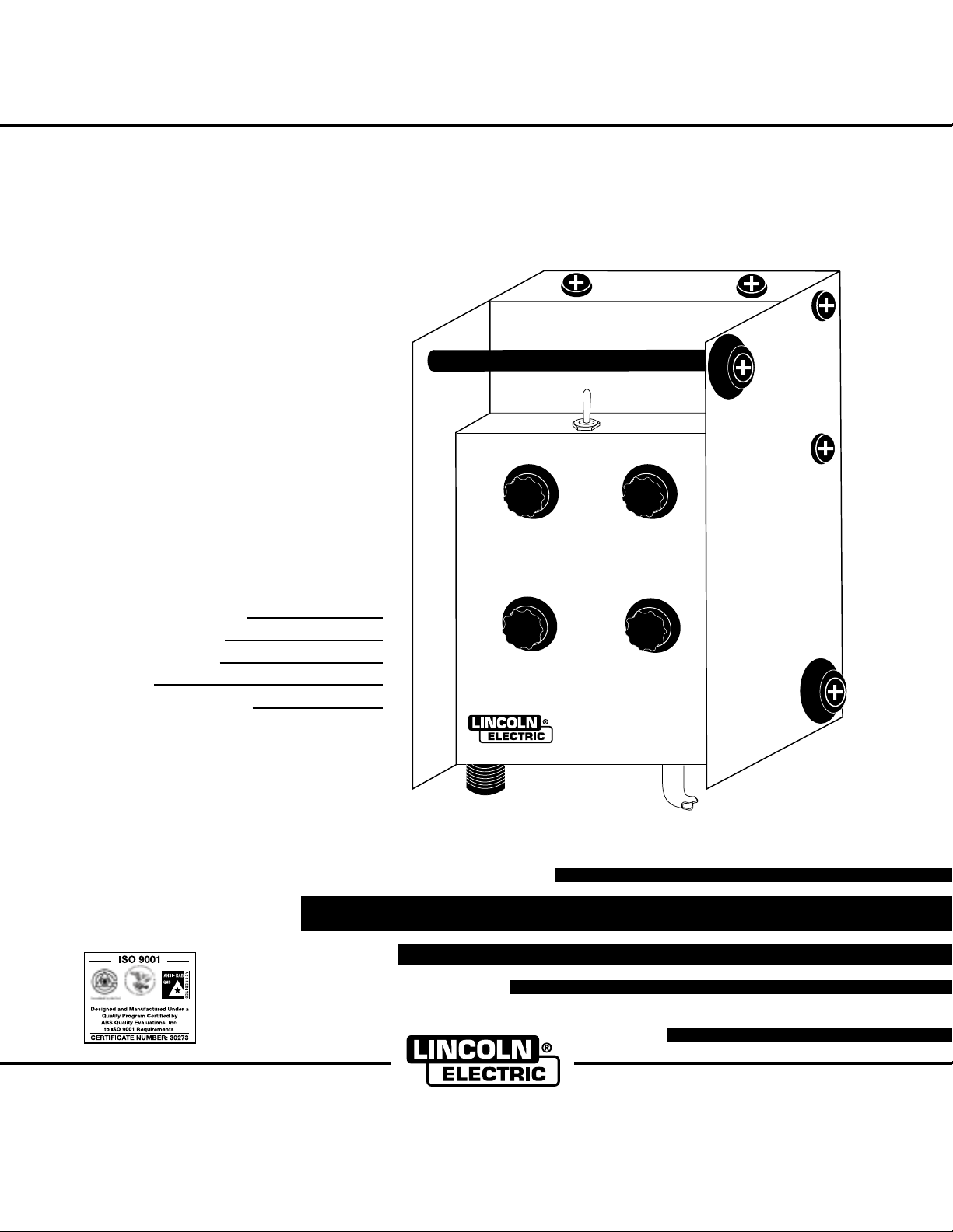
TIG PULSER
RETURN TO MAIN MENU
IM611-B
October,2001
For use with machines having Code Numbers:
Safety Depends on You
Lincoln arc welding and cutting
equipment is designed and built
with safety in mind. However, your
overall safety can be increased
by proper installation ... and
thoughtful operation on your part.
DO NOT INSTALL, OPERATE
OR REPAIR THIS EQUIPMENT
WITHOUT READING THIS MANUAL AND THE SAFETY PRECAUTIONS CONTAINED
THROUGHOUT. And, most
importantly, think before you act
and be careful.
10472,
10606
10735
Date of Purchase:
Serial Number:
Code Number:
Model:
Where Purchased:
TIG PULSER
OPERATOR’S MANUAL
Cleveland, Ohio 44117-1199 U.S.A. TEL: 216.481.8100 FAX: 216.486.1751 WEB SITE: www.lincolnelectric.com
• World's Leader in Welding and Cutting Products •
• Sales and Service through Subsidiaries and Distributors Worldwide •
Page 2
i
SAFETY
WARNING
CALIFORNIA PROPOSITION 65 WARNINGS
For Diesel Engines: Diesel engine exhaust and
some of its constituents are known to the State
of California to cause cancer, birth defects, and
other reproductive harm.
ARC WELDING CAN BE HAZARDOUS. PROTECT YOURSELF AND OTHERS FROM POSSIBLE SERIOUS INJURY OR DEATH.
KEEP CHILDREN AWAY. PACEMAKER WEARERS SHOULD CONSULT WITH THEIR DOCTOR BEFORE OPERATING.
Read and understand the following safety highlights. For additional safety information, it is strongly recommended that you purchase a copy of “Safety in Welding & Cutting - ANSI Standard Z49.1” from the American Welding Society, P.O. Box 351040,
Miami, Florida 33135 or CSA Standard W117.2-1974. A Free copy of “Arc Welding Safety” booklet E205 is available from the
Lincoln Electric Company, 22801 St. Clair Avenue, Cleveland, Ohio 44117-1199.
BE SURE THAT ALL INSTALLATION, OPERATION, MAINTENANCE AND REPAIR PROCEDURES ARE
PERFORMED ONLY BY QUALIFIED INDIVIDUALS.
For Gasoline Engines: The engine exhaust from
this product contains chemicals known to the
State of California to cause cancer, birth defects,
or other reproductive harm.
i
FOR ENGINE
powered equipment.
1.a. Turn the engine off before troubleshooting and maintenance
work unless the maintenance work requires it to be running.
____________________________________________________
1.b.Operate engines in open, well-ventilated
areas or vent the engine exhaust fumes
outdoors.
____________________________________________________
1.c. Do not add the fuel near an open flame weld-
ing arc or when the engine is running. Stop
the engine and allow it to cool before refueling to prevent spilled fuel from vaporizing on
contact with hot engine parts and igniting. Do
not spill fuel when filling tank. If fuel is spilled,
wipe it up and do not start engine until fumes
have been eliminated.
____________________________________________________
1.d. Keep all equipment safety guards, coversand devices in position and in good repair.Keep hands, hair, clothing and tools
away from V-belts, gears, fans and all other moving parts
when starting, operating or repairing equipment.
____________________________________________________
1.e. In some cases it may be necessary to remove safety
guards to perform required maintenance. Remove
guards only when necessary and replace them when the
maintenance requiring their removal is complete.
Always use the greatest care when working near moving
parts.
___________________________________________________
1.f. Do not put your hands near the engine fan. Do
not attempt to override the governor or idler
by pushing on the throttle control rods while
the engine is running.
1.h. To avoid scalding, do not remove the
radiator pressure cap when the engine is
hot.
ELECTRIC AND
MAGNETIC FIELDS
may be dangerous
2.a. Electric current flowing through any conductor causes
localized Electric and Magnetic Fields (EMF). Welding
current creates EMF fields around welding cables and
welding machines
2.b. EMF fields may interfere with some pacemakers, and
welders having a pacemaker should consult their physician
before welding.
2.c. Exposure to EMF fields in welding may have other health
effects which are now not known.
2.d. All welders should use the following procedures in order to
minimize exposure to EMF fields from the welding circuit:
2.d.1.
Route the electrode and work cables together - Secure
them with tape when possible.
2.d.2. Never coil the electrode lead around your body.
2.d.3. Do not place your body between the electrode and
work cables. If the electrode cable is on your right
side, the work cable should also be on your right side.
___________________________________________________
1.g. To prevent accidentally starting gasoline engines while
turning the engine or welding generator during maintenance
work, disconnect the spark plug wires, distributor cap or
magneto wire as appropriate.
2.d.4. Connect the work cable to the workpiece as close as
possible to the area being welded.
2.d.5. Do not work next to welding power source.
Mar ‘95
Page 3
ii
SAFETY
ii
ELECTRIC SHOCK can kill.
3.a. The electrode and work (or ground) circuits
are electrically “hot” when the welder is on.
Do not touch these “hot” parts with your bare
skin or wet clothing. Wear dry, hole-free
gloves to insulate hands.
3.b. Insulate yourself from work and ground using dry insulation.
Make certain the insulation is large enough to cover your full
area of physical contact with work and ground.
In addition to the normal safety precautions, if welding
must be performed under electrically hazardous
conditions (in damp locations or while wearing wet
clothing; on metal structures such as floors, gratings or
scaffolds; when in cramped positions such as sitting,
kneeling or lying, if there is a high risk of unavoidable or
accidental contact with the workpiece or ground) use
the following equipment:
• Semiautomatic DC Constant Voltage (Wire) Welder.
• DC Manual (Stick) Welder.
• AC Welder with Reduced Voltage Control.
3.c. In semiautomatic or automatic wire welding, the electrode,
electrode reel, welding head, nozzle or semiautomatic
welding gun are also electrically “hot”.
3.d. Always be sure the work cable makes a good electrical
connection with the metal being welded. The connection
should be as close as possible to the area being welded.
3.e. Ground the work or metal to be welded to a good electrical
(earth) ground.
3.f.
Maintain the electrode holder, work clamp, welding cable and
welding machine in good, safe operating condition. Replace
damaged insulation.
3.g. Never dip the electrode in water for cooling.
3.h. Never simultaneously touch electrically “hot” parts of
electrode holders connected to two welders because voltage
between the two can be the total of the open circuit voltage
of both welders.
3.i. When working above floor level, use a safety belt to protect
yourself from a fall should you get a shock.
3.j. Also see Items 6.c. and 8.
ARC RAYS can burn.
4.a. Use a shield with the proper filter and cover
plates to protect your eyes from sparks and
the rays of the arc when welding or observing
open arc welding. Headshield and filter lens
should conform to ANSI Z87. I standards.
4.b. Use suitable clothing made from durable flame-resistant
material to protect your skin and that of your helpers from
the arc rays.
4.c. Protect other nearby personnel with suitable, non-flammable
screening and/or warn them not to watch the arc nor expose
themselves to the arc rays or to hot spatter or metal.
FUMES AND GASES
can be dangerous.
5.a. Welding may produce fumes and gases
hazardous to health. Avoid breathing these
fumes and gases.When welding, keep
your head out of the fume. Use enough
ventilation and/or exhaust at the arc to keep
fumes and gases away from the breathing zone. When
welding with electrodes which require special
ventilation such as stainless or hard facing (see
instructions on container or MSDS) or on lead or
cadmium plated steel and other metals or coatings
which produce highly toxic fumes, keep exposure as
low as possible and below Threshold Limit Values (TLV)
using local exhaust or mechanical ventilation. In
confined spaces or in some circumstances, outdoors, a
respirator may be required. Additional precautions are
also required when welding on galvanized steel.
5.b.
Do not weld in locations near chlorinated hydrocarbon
coming from degreasing, cleaning or spraying operations.
The heat and rays of the arc can react with solvent vapors
form phosgene, a highly toxic gas, and other irritating
products.
5.c. Shielding gases used for arc welding can displace air and
cause injury or death. Always use enough ventilation,
especially in confined areas, to insure breathing air is safe.
5.d. Read and understand the manufacturer’s instructions for this
equipment and the consumables to be used, including the
material safety data sheet (MSDS) and follow your
employer’s safety practices. MSDS forms are available from
your welding distributor or from the manufacturer.
vapors
to
5.e. Also see item 1.b.
Mar ‘95
Page 4
iii
SAFETY
iii
WELDING SPARKS can
cause fire or explosion.
6.a.
Remove fire hazards from the welding area.
If this is not possible, cover them to prevent
the welding sparks from starting a fire.
materials from welding can easily go through small cracks
and openings to adjacent areas. Avoid welding near
hydraulic lines. Have a fire extinguisher readily available.
6.b. Where compressed gases are to be used at the job site,
special precautions should be used to prevent hazardous
situations. Refer to “Safety in Welding and Cutting” (ANSI
Standard Z49.1) and the operating information for the
equipment being used.
6.c. When not welding, make certain no part of the electrode
circuit is touching the work or ground. Accidental contact can
cause overheating and create a fire hazard.
6.d. Do not heat, cut or weld tanks, drums or containers until the
proper steps have been taken to insure that such procedures
will not cause flammable or toxic vapors from substances
inside. They can cause an explosion even
been “cleaned”. For information, purchase “Recommended
Safe Practices for the
Containers and Piping That Have Held Hazardous
Substances”, AWS F4.1 from the American Welding Society
(see address above).
6.e. Vent hollow castings or containers before heating, cutting or
welding. They may explode.
Sparks and spatter are thrown from the welding arc. Wear oil
6.f.
free protective garments such as leather gloves, heavy shirt,
cuffless trousers, high shoes and a cap over your hair. Wear
ear plugs when welding out of position or in confined places.
Always wear safety glasses with side shields when in a
welding area.
6.g. Connect the work cable to the work as close to the welding
area as practical. Work cables connected to the building
framework or other locations away from the welding area
increase the possibility of the welding current passing
through lifting chains, crane cables or other alternate circuits.
This can create fire hazards or overheat lifting chains or
cables until they fail.
6.h. Also see item 1.c.
Remember that welding sparks and hot
though
they have
Preparation
for Welding and Cutting of
CYLINDER may explode
if damaged.
7.a. Use only compressed gas cylinders
containing the correct shielding gas for the
process used and properly operating
regulators designed for the gas and
pressure used. All hoses, fittings, etc. should be suitable for
the application and maintained in good condition.
7.b. Always keep cylinders in an upright position securely
chained to an undercarriage or fixed support.
7.c. Cylinders should be located:
• Away from areas where they may be struck or subjected to
physical damage.
• A safe distance from arc welding or cutting operations and
any other source of heat, sparks, or flame.
7.d. Never allow the electrode, electrode holder or any other
electrically “hot” parts to touch a cylinder.
7.e. Keep your head and face away from the cylinder valve outlet
when opening the cylinder valve.
7.f. Valve protection caps should always be in place and hand
tight except when the cylinder is in use or connected for
use.
7.g. Read and follow the instructions on compressed gas
cylinders, associated equipment, and CGA publication P-l,
“Precautions for Safe Handling of Compressed Gases in
Cylinders,” available from the Compressed Gas Association
1235 Jefferson Davis Highway, Arlington, VA 22202.
FOR ELECTRICALLY
powered equipment.
8.a. Turn off input power using the disconnect
switch at the fuse box before working on
the equipment.
8.b. Install equipment in accordance with the U.S. National
Electrical Code, all local codes and the manufacturer’s
recommendations.
8.c. Ground the equipment in accordance with the U.S. National
Electrical Code and the manufacturer’s recommendations.
Mar ‘95
Page 5

iv
SAFETY
iv
PRÉCAUTIONS DE SÛRETÉ
Pour votre propre protection lire et observer toutes les instructions
et les précautions de sûreté specifiques qui parraissent dans ce
manuel aussi bien que les précautions de sûreté générales suivantes:
Sûreté Pour Soudage A L’Arc
1. Protegez-vous contre la secousse électrique:
a. Les circuits à l’électrode et à la piéce sont sous tension
quand la machine à souder est en marche. Eviter toujours
tout contact entre les parties sous tension et la peau nue
ou les vétements mouillés. Porter des gants secs et sans
trous pour isoler les mains.
b. Faire trés attention de bien s’isoler de la masse quand on
soude dans des endroits humides, ou sur un plancher metallique ou des grilles metalliques, principalement dans
les positions assis ou couché pour lesquelles une grande
partie du corps peut être en contact avec la masse.
c. Maintenir le porte-électrode, la pince de masse, le câble de
soudage et la machine à souder en bon et sûr état defonctionnement.
d.Ne jamais plonger le porte-électrode dans l’eau pour le
refroidir.
e. Ne jamais toucher simultanément les parties sous tension
des porte-électrodes connectés à deux machines à souder parce que la tension entre les deux pinces peut être le
total de la tension à vide des deux machines.
f. Si on utilise la machine à souder comme une source de
courant pour soudage semi-automatique, ces precautions
pour le porte-électrode s’applicuent aussi au pistolet de
soudage.
6. Eloigner les matériaux inflammables ou les recouvrir afin de
prévenir tout risque d’incendie dû aux étincelles.
7. Quand on ne soude pas, poser la pince à une endroit isolé de
la masse. Un court-circuit accidental peut provoquer un
échauffement et un risque d’incendie.
8. S’assurer que la masse est connectée le plus prés possible de
la zone de travail qu’il est pratique de le faire. Si on place la
masse sur la charpente de la construction ou d’autres endroits
éloignés de la zone de travail, on augmente le risque de voir
passer le courant de soudage par les chaines de levage,
câbles de grue, ou autres circuits. Cela peut provoquer des
risques d’incendie ou d’echauffement des chaines et des
câbles jusqu’à ce qu’ils se rompent.
9. Assurer une ventilation suffisante dans la zone de soudage.
Ceci est particuliérement important pour le soudage de tôles
galvanisées plombées, ou cadmiées ou tout autre métal qui
produit des fumeés toxiques.
10. Ne pas souder en présence de vapeurs de chlore provenant
d’opérations de dégraissage, nettoyage ou pistolage. La
chaleur ou les rayons de l’arc peuvent réagir avec les vapeurs
du solvant pour produire du phosgéne (gas fortement toxique)
ou autres produits irritants.
11. Pour obtenir de plus amples renseignements sur la sûreté, voir
le code “Code for safety in welding and cutting” CSA Standard
W 117.2-1974.
2. Dans le cas de travail au dessus du niveau du sol, se protéger
contre les chutes dans le cas ou on recoit un choc. Ne jamais
enrouler le câble-électrode autour de n’importe quelle partie
du corps.
3. Un coup d’arc peut être plus sévère qu’un coup de soliel,
donc:
a. Utiliser un bon masque avec un verre filtrant approprié
ainsi qu’un verre blanc afin de se protéger les yeux du rayonnement de l’arc et des projections quand on soude ou
quand on regarde l’arc.
b. Porter des vêtements convenables afin de protéger la peau
de soudeur et des aides contre le rayonnement de l‘arc.
c. Protéger l’autre personnel travaillant à proximité au
soudage à l’aide d’écrans appropriés et non-inflammables.
4. Des gouttes de laitier en fusion sont émises de l’arc de
soudage. Se protéger avec des vêtements de protection libres
de l’huile, tels que les gants en cuir, chemise épaisse, pantalons sans revers, et chaussures montantes.
5. Toujours porter des lunettes de sécurité dans la zone de
soudage. Utiliser des lunettes avec écrans lateraux dans les
zones où l’on pique le laitier.
PRÉCAUTIONS DE SÛRETÉ POUR
LES MACHINES À SOUDER À
TRANSFORMATEUR ET À
REDRESSEUR
1. Relier à la terre le chassis du poste conformement au code de
l’électricité et aux recommendations du fabricant. Le dispositif
de montage ou la piece à souder doit être branché à une
bonne mise à la terre.
2. Autant que possible, I’installation et l’entretien du poste seront
effectués par un électricien qualifié.
3. Avant de faires des travaux à l’interieur de poste, la debrancher à l’interrupteur à la boite de fusibles.
4. Garder tous les couvercles et dispositifs de sûreté à leur
place.
Mar. ‘93
Page 6

for selecting a QUALITY product by Lincoln Electric. We want you
Thank You
to take pride in operating this Lincoln Electric Company product •••
as much pride as we have in bringing this product to you!
Please Examine Carton and Equipment For Damage Immediately
When this equipment is shipped, title passes to the purchaser upon receipt by the carrier. Consequently, Claims
for material damaged in shipment must be made by the purchaser against the transportation company at the
time the shipment is received.
Please record your equipment identification information below for future reference.This information can be found
on your machine nameplate.
Model Name & Number _____________________________________
Code & Serial Number _____________________________________
Date of Purchase _____________________________________
Whenever you request replacement parts for or information on this equipment always supply the information you
have recorded above.
vv
Read this Operators Manual completely before attempting to use this equipment. Save this manual and keep it
handy for quick reference. Pay particular attention to the safety instructions we have provided for your protection.
The level of seriousness to be applied to each is explained below:
WARNING
This statement appears where the information must be followed exactly to avoid serious personal injury or
loss of life.
CAUTION
This statement appears where the information must be followed to avoid minor personal injury or damage to
this equipment.
Page 7

TABLE OF CONTENTS
Page
SAFETY .......................................................................................................................................i-iv
INSTALLATION................................................................................................................Section A
TECHNICAL SPECIFICATIONS...........................................................................................A.1
SAFETY PRECAUTIONS.....................................................................................................A.2
LOCATION............................................................................................................................A.2
MOUNTING BRACKETS......................................................................................................A.2
HIGH FREQUENCY INTERFERENCE PROTECTION .......................................................A.2
ELECTRICAL INPUT CONNECTIONS................................................................................A.2
MACHINE GROUNDING...............................................................................................A.2
SUPPLY CONNECTIONS .............................................................................................A.2
CONNECTION TO A TIG POWER SOURCE...............................................................A-2
CONTROL CABLE CONNECTION...............................................................................A.3
OUTPUT CABLES FOR PULSE WELDING ........................................................................A.3
OPERATION.....................................................................................................................Section B
SAFETY PRECAUTIONS.....................................................................................................B.1
GENERAL DESCRIPTION...................................................................................................B.1
OPERATIONAL FEATURES AND CONTROLS............................................................B.1
DESIGN FEATURES AND ADVANTAGES....................................................................B.2
WELDING CAPABILITY .......................................................................................................B.2
LIMITATIONS ........................................................................................................................B.2
POWER SOURCE SETTINGS.............................................................................................B.2
TIG PULSER CONTROLS AND SETTINGS .......................................................................B.2
vivi
MAINTENANCE...............................................................................................................Section C
TROUBLESHOOTING.....................................................................................................Section D
DIAGRAMS ......................................................................................................................Section E
WIRING DIAGRAM ..............................................................................................................E.1
PARTS MANUAL ....................................................................................................................P-313
TIG PULSER
Page 8
A-1
INSTALLATION
TECHNICAL SPECIFICATIONS - TIG PULSER
INPUT
Model Description Volts mAmps Frequency
K1619-1 TIG Pulser 5 VDC 25 mA DC
OUTPUT
Output Frequency Peak Current Background Current Peak Pulse Width
Range Range (% on Time)
Min. to 90% Max. 0 to 100% of Peak 10% to 90%
0.5 to 20 Hz of Power Source Rating Current Setting of cycle
PHYSICAL DIMENSIONS
HEIGHT WIDTH DEPTH WEIGHT
3.5 in. 5.0 in. 8.0 in. 4.6 lbs (2.1 kg)
(with cable)
89(mm) 127(mm) 203(mm)
A-1
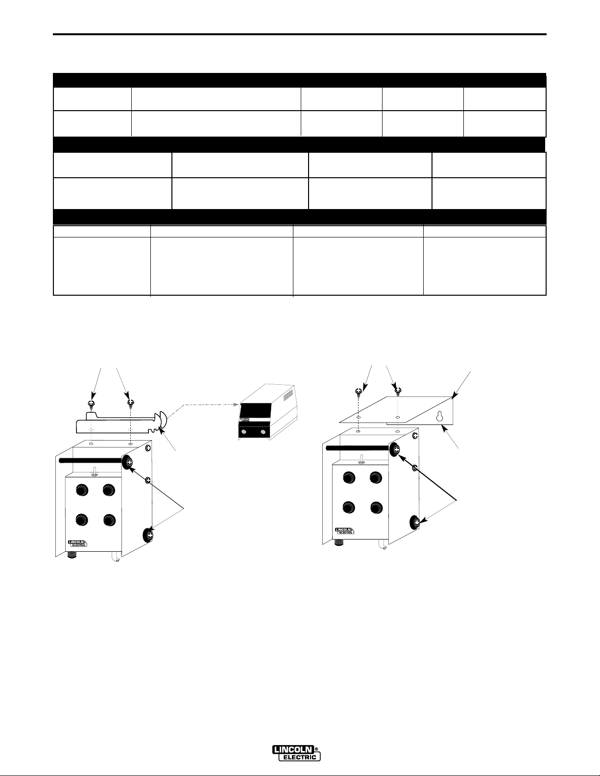
EXISTING CASE TOP SCREWS
SQUARE WAVE TIG 275
“HOOK” BRACKET
PROTECTIVE
RUBBER BUMBER
TIG PULSER
Figure A.1a - ”Hook” Bracket Installation for
mounting to a TIG Power
Source.
EXISTING CASE TOP SCREWS
TIG PULSER
UNIVERSAL BRACKET
MOUNTING HOLES TO
SECURE TO GENERIC
SURFACE
PROTECTIVE
RUBBER BUMBER
Figure A.1b - Universal Mounting Bracket
Installation for mounting to a
generic surface.
TIG PULSER
Page 9

A-2
INSTALLATION
A-2
Read this entire installation section before you
start installation.
SAFETY PRECAUTIONS
WARNING
ELECTRIC SHOCK can kill.
•Only qualified personnel should perform this installation.
•Turn the input power OFF at the disconnect switch or fuse box before working on this equipment.
•Do not touch electrically hot parts.
•Always connect the SW TIG 275
grounding terminal to a good electrical
earth ground.
------------------------------------------------------------------------
Only qualified personnel should install, use or service
this equipment
LOCATION
The second bracket is a universal bracket that is
designed to allow the TIG Pulser to be fastened to any
secure surface. Attach the bracket to the desired surface.Then attach the TIG Pulser to the universal bracket using the two screws from the top of the TIG Pulser
as shown in Figure A.1b.
HIGH FREQUENCY INTERFERENCE
PROTECTION
A TIG Pulser is suitable for use near a high frequency
arc starter because the circuitry in the TIG Pulser has
been specially designed for this situation.
ELECTRICAL INPUT CONNECTIONS
MACHINE GROUNDING
The TIG Pulser is grounded to the power source by the
ground lead carried inside the Control Cable. Ground
the power source according to all local and national
electrical codes. Also refer to the power source operator’s manual for any other grounding considerations.
The TIG Pulser can be used in the same locations and
environments as the power source. It is rated for use
in damp, dirty environments.
MOUNTING BRACKETS
The TIG Pulser has rubber feet that allow it to be set on
top of the machine or any flat surface. Two mounting
brackets are also provided for a more secure mounting.
Locate the two mounting brackets that are supplied
with the TIG Pulser in the loose parts bag. To prevent
accidentally dropping the unit, always secure the TIG
Pulser to a stable surface with one of the brackets.
The first bracket is designed to hook onto the left side
of a SW TIG 175, SW TIG 275 or like compatible power
source, allowing the TIG Pulser to be located next to
the machine control panel. Attach this bracket as
shown in Figure A.1a by using the two screws from the
top of the TIG Pulser. Tilt the Pulser to engage the hook
of the bracket into the slots on the top left side of the
power source then swing down so the rubber bumper
is against the case side and hook slots drop over the
bottom of the side slots. To remove; lift up and swing
out to disengage the hook bracket.
SUPPLY CONNECTIONS
The TIG Pulser receives its input power from the power
source through the Control Cable.
CONNECTION TO A POWER SOURCE
WARNING
Turn the Power switch on the power source “OFF”
before connecting or disconnecting input power lines,
output cables or control cables.
------------------------------------------------------------------------
TIG PULSER
Page 10

A-3
INSTALLATION
A-3
CONTROL CABLE CONNECTION
Refer to Figure A.2.
1. Connect the 6-pin cable plug of the TIG Pulser to
the Amptrol receptacle of the power source. If the
optional 25 foot Control Cable Extension is used, it
should be plugged into the Amptrol receptacle of
the power source and then into the TIG Pulser
cable. Only one control cable should be used; do
not series multiple extensions together. Using 50
foot or longer control cables may lead to poor welding performance.
2. Connect a foot Amptrol (shown), hand Amptrol or
an Arc Start Switch to the Tig Pulser see Figure A.2
Control cable connection.
3. Set the AMPERAGE control knob on the power
source to MAX position. Note: The pulser won't
properly function if the Amperage control is not
set at maximum.
4. Set the mode switch on power source to 2-step or
4-step TIG depending on the process being used.
Note: If the mode switch is set at Stick, the
Pulser won't have any control on the power
source and the power source will give maximum
output.
OUTPUT CABLES FOR PULSE
WELDING
Pulse welding generates high peak currents, which in
turn cause large voltage drops in welding cables. It is
essential that large cables (2/0 minimum) are used and
that all connections are clean and tight.
Because of voltage drops, the total length of the welding leads (work lead length plus electrode lead length)
should not exceed 50 feet. If longer cables are used,
the welding performance may be degraded.
NOTE: Do not coil the output cables around any
metal object.
SOURCE
FOOT AMPTROL
(SHOWN)
OR
HAND AMPTROL
OR
ARC START
SWITCH
TIG
PULSER
Figure A.2 Control Cable Connection.
TIG
POWER
REMOTE
RECEPTACLE
TIG PULSER
Page 11

B-1
OPERATION
B-1
SAFETY PRECAUTIONS
Read this entire section before operating the unit.
Additionally, read the power source operator’s manual
before operating this unit.
WARNING
ELECTRIC SHOCK
can kill.
•Do not touch electrically live parts such
as output terminals or internal wiring.
•Insulate yourself from the work and
ground.
•Always wear dry insulating gloves.
------------------------------------------------------------------------
FUMES AND GASES
can be dangerous.
•Keep your head out of fumes.
•Use ventilation or exhaust to remove
fumes from breathing zone.
------------------------------------------------------------------------
WELDING SPARKS
can cause fire or
explosion.
•Keep flammable material away.
•Do not weld on containers that have
held combustibles.
------------------------------------------------------------------------
ARC RAYS
can burn.
GENERAL DESCRIPTION
The TIG Pulser is a “pendant” type GTAW Pulsing
option for the SW TIG 175, SW TIG 275, or like compatible power source. It is a simple, easy-to-use unit,
with a minimum of controls. It supports the GTAW-P
(pulse TIG) process on mild steel, stainless steel, and
aluminum. The TIG Pulser features a 12 foot (3.7 m)
cable with plug and is supplied with brackets for mounting. A receptacle is provided for use with an optional
Amptrol or Arc Start Switch.
RECOMMENDED PROCESSES AND
EQUIPMENT
At the time of printing, the TIG Pulser is only recommended for use with the SW TIG 175 and the SW TIG
275 power source for GTAW-P (pulse TIG) procedures
within the capacity of the TIG power source.
The TIG Pulser may be used with an optional Hand
(K963) or Foot (K870) Amptrol or Arc Start Switch
(K814) for either 2-Step or 4-Step trigger mode. The 4step trigger mode or the Tig Pulser only works with
power source equipped with 4-step fiunction such as
the SW TIG 275.
OPERATIONAL FEATURES AND
CONTROLS
The TIG Pulser has the following controls as standard:
Peak Current, Background Current, % on Time (Peak
Pulse Width), and Pulses per Second (Frequency). All
are continuously adjustable thru control ranges.
•Wear eye, ear and body protection.
------------------------------------------------------------------------
Observe additional Safety Guidelines detailed in the
beginning of this manual.
TIG PULSER
Page 12

B-2
OPERATION
B-2
DESIGN FEATURES AND ADVANTAGES
• Simple controls make this unit easy to set up and
adjust.
• Operating power provided through the remote control
cable receptacle eliminating the need for an independent power supply.
• Accomodates Amptrol or Arc Start Switch in 2-step or
4-step trigger mode.
• Designed to the IEC-974-1 standard.
• Attractive, rugged case includes carrying handle and
rubber feet.
• Unit is supplied with one bracket for hanging on the
power source, and one “universal” bracket for mounting to vertical or horizontal surfaces.
WELDING CAPABILITY
The TIG Pulser provides GTAW-P capability for the SW
TIG power source up to 90% of the maximum current
capacity of the machine.
LIMITATIONS
POWER SOURCE SETTINGS
The power source AMPERAGE control knob must be
set at MAX. and the mode switch must be set at 2-step
or 4-step TIG. The polarity switch and other control
knobs on the power source can be set at any desired
position and will have the same effect as being operated without the TIG Pulser.
TIG PULSER CONTROLS AND SETTINGS
Refer to Figure B.1.
MODE switch
Located on the top side of the TIG Pulser. Set this
switch to one of the following three postitions:
• Set to Amptrol 2-step if welding in 2-step and want to
remotely control the welding current with a hand
Amptrol or a foot Amptrol.
• Set to Arc Start Switch 2-step if welding in 2-step
with an Arc Start Switch. Welding may be performed
in this mode with a hand Amptrol or a foot Amptrol,
however the current will not be remotely controlled
but controlled by the setting on the pulser
• Set to 4-step if welding in 4-step and the power
source is set to 4-step. Either an Arc Start Switch or
an Amptrol can be used, however current can only
be controlled by the pulser setting. Refer to the
power source instruction manual for 4-step TIG operation.
At the time of printing, the TIG Pulser is only recommended for use with the SW TIG 175 and the SW TIG
275 power source for GTAW-P (pulse TIG) procedures
within the capacity of the TIG power source. Check
power source Operator’s Manual before using with the
TIG Pulser.
TIG PULSER
ARC START SWITCH
2-STEP
AMPTROL
2-STEP
PEAK
CURRENT
% ON TIME
ARC START
SWITCH
OR AMPTROL
4-STEP
BACKGROUND
CURRENT
PULSES PER
SECOND
TIG PULSER
Figure B.1 TIG PULSER Controls
Page 13

B-3
OPERATION
B-3
PEAK CURRENT knob
If the mode switch is set to Amptrol 2-step, the peak
welding current can be controlled by an Amptrol from
minimum up to the limit set by this knob.
If the mode switch is set to either the Arc Start Switch
2-step position or the 4-step position, the setting on
this knob determines the peak welding current.
Note: The MAX position on this knob is equivalent to
about 90% of the maximum output current of the
power source.
This setting adjusts the wetting and bead shape during the peak pulse time of each cycle.
TIG PULSER PRESET
When using the TIG Pulser with a power source with
the preset capability, the peak welding current can be
preset with the Peak Current knob on the TIG Pulser.
• Preset in 2-step TIG mode:
Adjust the Peak Current and read the preset on the
power source display. For TIG Pulser code number
10472, when mode switch is set to Amptrol 2-step
the power source will always display the minimum
preset; to preset the peak current set the mode
switch to Arc Start Switch 2-step and adjust the
Peak Current then set to Amptrol 2-step if welding
with an Amptrol.
• Preset in 4-step TIG mode:
Set the Background Current to PULSER OFF position, adjust the Peak Current to preset, then set the
Background Current to the desired level.
In 4-step TIG mode the preset alternates between
peak and background currents when the
Background Current is not set at pulser off position, and therefore the power source display also
alternates between peak and background currents.
BACKGROUND CURRENT knob
Use this knob to set the background current as a percentage of the peak current. If set at PULSER OFF
position, the welding current will be normal as if welding without the TIG Pulser, that way non-pulsing welding can be done without having to disconnect the TIG
Pulser.
• This setting is adjusted as low as will maintain the
arc during the background current time. 40 - 60% is
a typical starting point.
% ON TIME knob
This knob controls the duration of the peak current as
a percentage of one pulse cycle. For instance if set at
40%, the welding current will remain at peak for 40% of
one pulse cycle and at the background current for 60%
of one pulse cycle.
• This setting controls the total heat of the weld as a
balance between peak pulse and background times
affecting distortion and burnthrough. 40 - 60% is a
typical starting point.
PULSES PER SECOND knob
Use this knob to set the frequency or the number of
pulses per second, from 0.5 pulse per second to 20
pulses per second.
• This setting adjusts bead shape to travel speed.
Thinner plate with faster travel speed will require
higher frequency than thicker plate with slower travel
speed. 2 - 3 is a typical starting point.
The following table may be used as a guide line to preset the TIG Pulser when connecting to a SW TIG 175:
TIG PULSER SW TIG 175
PEAK CURRENT OUTPUT CURRENT
DIAL REFERENCE (AMPS)
MIN. 10
125
235
345
455
565
675
790
8 110
9 135
MAX. 160
TIG PULSER
Page 14

C-1
MAINTENANCE
GENERAL MAINTENANCE
No regular or periodic maintenance is required for the
TIG Pulser. As with any welding equipment, occasionally clean the exterior of the unit with a low pressure
airstream or a damp cloth. This keeps the front and
rear nameplates in a readable condition. Replace any
nameplates that become illegible.
C-1
TIG PULSER
Page 15

D-1
TROUBLESHOOTING
HOW TO USE TROUBLESHOOTING GUIDE
WARNING
Service and Repair should only be performed by Lincoln Electric Factory Trained Personnel.
Unauthorized repairs performed on this equipment may result in danger to the technician
and machine operator and will invalidate your factory warranty. For your safety and to avoid
Electrical Shock, please observe all safety notes and precautions detailed throughout this
manual.
__________________________________________________________________________
This Troubleshooting Guide is provided to
help you locate and repair possible machine
malfunctions. Simply follow the three-step
procedure listed below.
D-1
Step 1. LOCATE PROBLEM (SYMPTOM).
Look under the column labeled “PROBLEM
(SYMPTOMS)”. This column describes possible symptoms that the machine may exhibit. Find the listing that best describes the
symptom that the machine is exhibiting.
Symptoms are grouped into the following
categories: engine problems, function problems and output problems.
Step 2. PERFORM EXTERNAL TESTS.
The second column labeled “POSSIBLE
AREAS OF MISADJUSTMENT(S)” lists the
obvious external possibilities that may contribute to the machine symptom. Perform
these tests/checks in the order listed. In
general, these tests can be conducted without removing the case wrap-around cover.
Step 3. RECOMMENDED COURSE OF
ACTION
If you have exhausted all of the items in step
2. Contact your Local Lincoln Authorized
Field Service Facility.
CAUTION
If for any reason you do not understand the test procedures or are unable to perform the tests/repairs safely, contact your Local
Lincoln Authorized Field Service Facility for technical troubleshooting assistance before you proceed.
TIG PULSER
Page 16

D-2
TROUBLESHOOTING
Observe all Safety Guidelines detailed througout this manual
D-2
PROBLEMS
(SYMPTOMS)
No output.
Max. welding current and Tig Pulser
has no control.
Remote hand or foot Amptrol has no
control on welding current.
Always has min. welding current
when using Arc Start Switch.
POSSIBLE AREAS OF
MISADJUSTMENTS(S)
GENERAL PROBLEMS
1. The AMPERAGE knob on power
source is not set at MAX.
2. Power source & Tig Pulser connection is wrong.
3. Defective Pulser PC board.
1. MODE switch on power source is
set at STICK position.
2. Defective Pulser PC board.
1. MODE switch on Tig Pulser is not
set at Amptrol 2-step.
2. Defective Pulser PC board.
1. MODE switch on Tig Pulser is set
at Amptrol.
RECOMMENDED
COURSE OF ACTION
1. Set AMPERAGE knob at MAX.
2. See Installation & Connection section
for proper connection.
3. Replace Pulser PC board.
1. Set MODE switch on power source to
2-step or 4-step TIG.
2. Replace Pulser PC board.
1. Set MODE switch on Tig Pulser to
Amptrol 2-step.
2. Replace Pulser PC board.
1. Set MODE switch on Tig Pulser to Arc
Start Switch 2-step if welding in 2-step,
or to 4-step if welding in 4-step.
Remote Amptrol has no control on
the welding current in 4-step.
Welds but does not pulse.
2. Wiring at Peak Current potentiometer is broken.
3. Defective Pulser PC board.
Nothing is wrong, in 4-step mode the
welding current is controlled only by
the Peak Current knob on Pulser.
1. Background current is set at
PULSER OFF position.
2. Wring at Pulses per Second
potentiometer is broken.
3. Defective Pulser PC board.
2. Check wiring at Peak Current potentiometer.
3. Replace Pulser PC board.
1. Set Background current to desired
position.
2. Check wiring at Pulses per Second
potentiometer.
3. Replace Pulser PC board.
CAUTION
If for any reason you do not understand the test procedures or are unable to perform the tests/repairs safely, contact your Local
Lincoln Authorized Field Service Facility for technical troubleshooting assistance before you proceed.
TIG PULSER
Page 17

D-3
TROUBLESHOOTING
Observe all Safety Guidelines detailed througout this manual
D-3
PROBLEMS
(SYMPTOMS)
2-STEP TIG WELDING PROBLEMS
Hi-Freq kicking in and out while welding in DC.
No Hi-Freq or no gas, can not start.
Low welding current.
Does not pulse.
POSSIBLE AREAS OF
MISADJUSTMENTS(S)
1. Background Current is set too low.
2. Defective power source.
1. Power source & Tig Pulser connection is wrong.
2. Defective power source.
1. Power source is set at 4-step Tig.
2. Defective Pulser PC board.
1. MODE switch on Tig Pulser is set
at 4-step.
2. Defective Pulser PC board.
RECOMMENDED
COURSE OF ACTION
1. Set Background Current to desired
position.
2. Check power source.
1. See Installation & Connection section
for proper connection.
2. Check power source.
1. Set power source to 2-step TIG.
2. Replace Pulser PC board.
1. Set MODE switch on Tig Pulser to 2step.
2. Replace Pulser PC board.
PROBLEMS
(SYMPTOMS)
4-STEP TIG WELDING PROBLEMS
Does not pulse when trigger closed.
Does not pulse when trigger open.
No output.
Welding current goes off after starting.
POSSIBLE AREAS OF
MISADJUSTMENTS(S)
Nothing is wrong, only pulse during
welding when trigger is open.
1. MODE switch on Tig Pulser is not
set at 4-step.
2. Defective Pulser PC board.
1. Mode switch on power source is
set at 2-step TIG.
2. Defective power source.
1. Background Current and/or Peak
Current set too low.
2. Defective power source.
RECOMMENDED
COURSE OF ACTION
1. Set MODE switch to 4-step.
2. Replace Pulser PC board.
1. Set MODE switch on power source to
4-step.
2. Check power source.
1. Set Background Current and Peak
Current to desired position.
2. Check power source.
CAUTION
If for any reason you do not understand the test procedures or are unable to perform the tests/repairs safely, contact your Local
Lincoln Authorized Field Service Facility for technical troubleshooting assistance before you proceed.
TIG PULSER
Page 18

E-1
DIAGRAMS
WIRING DIAGRAM - TIG PULSER
E-1
J4
FOOT OR HAND
AMPTROL
CDA
B
L1
TOROID
P3
C
BDA
1
4
2
3
J3
CONTROL BOARD
CONNECTION
ARC START SWITCH
FORE
ARC START
E
5
6
S1
2-STEP
SWITCH
VIEWED FROM REAR
4-STEP
212
213
214
2-STEP
AMPTROL
201
PEAK
CURRENT
202
CW
R1
203
CURRENT
BACKGROUND
CW
204
205
P1
212
1
R2
206
202
2
214
3
201
4
211
5
1
208
6
% ON
208
207
205
207
J1
36527
4
TIME
CW
213
987
J2
209
203
10
R3
204
11
209
8
210
131412
210
206
PER
PULSES
SECOND
CW
R4
211
C-RW
M18917
601
602
603
601
1
TOROID
602
603
2
305
B
604
604
4
B
E
TIG PULSER WIRING DIAGRAM
F
C
J4
BD
AE
MATING VIEW
P2
J6
J1J3J2
P6
P5
B
A
SEQUENCE (COMPONENT SIDE VIEW)
F
C
E
D
P5
MATING VIEW
PC BOARD CONNECTOR CAVITY NO.
Note: This diagram may not be totally applicable to every code covered by this manual.
606
605
607
L2
606
607
605
6
7
W
G
U
F
D
A
CABLE
CONTROL
ASSEMBLY
608
608
8
R
C
CASE
FRONT
TIG PULSER
Page 19

NOTES
Page 20

PARTS LIST FOR
TIG PULSER
P-313P-313
This parts list is provided as an informative guide only.
This information was accurate at the time of printing. However, since these
pages are regularly updated in Lincoln Electric’s official Parts Book (BK-34),
always check with your Lincoln parts supplier for the latest parts information.
TIG PULSER
Page 21

Now Available...12th Edition
VISA
®
Mas ter Car dMasterCard
®
The Procedure Handbook of Arc Welding
With over 500,000 copies of previous editions published
since 1933, the Procedure Handbook is considered by many to
be the “Bible” of the arc welding industry.
This printing will go fast so don’t delay. Place your
order now using the coupon below.
The hardbound book contains over 750 pages of welding information, techniques and procedures. Much of this material
has never been included in any other book.
A must for all welders, supervisors, engineers and
designers. Many welding instructors will want to use the book as
a reference for all students by taking advantage of the low quantity discount prices which include shipping by
4th class parcel post.
$15.00 postage paid U.S.A. Mainland
How To Read Shop Drawings
The book contains the latest information and application
data on the American Welding Society Standard Welding
Symbols. Detailed discussion tells how engineers and draftsmen use the “short-cut” language of symbols to pass on
assembly and welding information to shop personnel.
New Lessons in Arc Welding
Lessons, simply written, cover manipulatory techniques;
machine and electrode characteristics; related subjects, such
as distortion; and supplemental information on arc welding
applications, speeds and costs. Practice materials, exercises,
questions and answers are suggested for each
lesson.
528 pages, well illustrated, 6” x 9” size, bound in simulated,
gold embossed leather.
$5.00 postage paid U.S.A.
Mainland
Need Welding Training?
The Lincoln Electric Company operates the oldest and
most respected Arc Welding School in the United States at its
corporate
have graduated. Tuition is low and the training is
“hands on”
For details write: Lincoln Welding School
headquarters in Cleveland, Ohio. Over 100,000 students
22801 St. Clair Ave.
Cleveland, Ohio 44117-1199.
Practical exercises and examples develop the reader’s
to visualize mechanically drawn objects as they will appear in
their assembled form.
187 pages with more than 100 illustrations. Size 8-1/2” x
Durable, cloth-covered board binding.
$4.50 postage paid U.S.A.
ability
11”
Mainland
and ask for bulletin ED-80 or call 216-383-2259 and ask
for the
Welding School Registrar.
Lincoln Welding School
BASIC COURSE $700.00
5 weeks of fundamentals
There is a 10% discount on all orders of $50.00 or more for shipment at one time to one location.
Orders of $50 or less before discount or orders outside of North America must be prepaid with charge, check or money order in U.S. Funds Only.
Prices include shipment by 4 th Class Book Rate for U.S.A. Mainland Only. Please allow up to 4 weeks for delivery.
UPS Shipping f
or North America Only. All prepaid orders that request UPS shipment please add:
$5.00 For order value up to $49.99
$10.00 For order value between $50.00 & $99.99
$15.00 For order value between $100.00 & $149.00
For North America invoiced orders over $50.00 & credit card orders, if UPS is requested, it will be invoiced or charged to you at cost.
Outside U.S.A. Mainland order must be prepaid in U.S. Funds. Please add $2.00 per book for surface mail or $15.00 per book for air parcel post shipment.
METHOD OF PAYMENT: (Sorry, No C.O.D. Orders)
CHECK ONE:
Please Invoice (only if order is over $50.00)
Check or Money Order Enclosed, U.S. Funds only
Credit Card - Telephone: _______________________________________________
Account No.
USE THIS FORM TO ORDER:
BOOKS OR FREE INFORMATIVE CATALOGS Telephone: 216-383-2211 or, for fastest service, FAX this completed form to: 216-361-5901.
|_|_|_|_|_|_|_|_|_|_|_|_|_|_|_|_|_|_|_|_|_|
Order from: BOOK DIVISION, The Lincoln Electric Company, 22801 St. Clair Avenue, Cleveland, Ohio 44117-1199
Exp Date
Name: _______________________________________________
Address: _______________________________________________
_______________________________________________
|_|_| |_|_|
Month Year
Signature as it appears on Charge Card:
______________________
Lincoln Welding School Titles: Price Code Quantity Cost
(ED-80)
Seminar Information Procedure Handbook “Twelfth Edition” $15.00 PH
(ED-45)
Educational Video Information Incentive Management $5.00 IM
(ED-93)
James F. Lincoln Arc Welding The American Century of John C. Lincoln $5.00 AC
Foundation Book Information Welding Preheat Calculator $3.00 WC-8
(JFLF-515)
New Lessons in Arc Welding $5.00 L
How to Read Shop Drawings $4.50 H
A New Approach to Industrial Economics $5.00 NA
Pipe Welding Charts $4.50 ED-89
SUB TOTAL
Additional Shipping Costs if any
TOTAL COST
Page 22

WARNING
Spanish
AVISO DE
PRECAUCION
● Do not touch electrically live parts or
electrode with skin or wet clothing.
● Insulate yourself from work and
ground.
● No toque las partes o los electrodos
bajo carga con la piel o ropa mojada.
● Aislese del trabajo y de la tierra.
● Keep flammable materials away.
● Mantenga el material combustible
fuera del área de trabajo.
● Wear eye, ear and body protection.
● Protéjase los ojos, los oídos y el
cuerpo.
French
ATTENTION
German
WARNUNG
Portuguese
ATENÇÃO
Japanese
Chinese
Korean
Arabic
● Ne laissez ni la peau ni des vête-
ments mouillés entrer en contact
avec des pièces sous tension.
● Isolez-vous du travail et de la terre.
● Berühren Sie keine stromführenden
Teile oder Elektroden mit Ihrem
Körper oder feuchter Kleidung!
● Isolieren Sie sich von den
Elektroden und dem Erdboden!
● Não toque partes elétricas e elec-
trodos com a pele ou roupa molhada.
● Isole-se da peça e terra.
● Gardez à l’écart de tout matériel
inflammable.
● Entfernen Sie brennbarres Material!
● Mantenha inflamáveis bem guarda-
dos.
● Protégez vos yeux, vos oreilles et
votre corps.
● Tragen Sie Augen-, Ohren- und Kör-
perschutz!
● Use proteção para a vista, ouvido e
corpo.
READ AND UNDERSTAND THE MANUFACTURER’S INSTRUCTION FOR THIS EQUIPMENT AND THE CONSUMABLES TO
BE USED AND FOLLOW YOUR EMPLOYER’S SAFETY PRACTICES.
SE RECOMIENDA LEER Y ENTENDER LAS INSTRUCCIONES DEL FABRICANTE PARA EL USO DE ESTE EQUIPO Y LOS
CONSUMIBLES QUE VA A UTILIZAR, SIGA LAS MEDIDAS DE SEGURIDAD DE SU SUPERVISOR.
LISEZ ET COMPRENEZ LES INSTRUCTIONS DU FABRICANT EN CE QUI REGARDE CET EQUIPMENT ET LES PRODUITS A
ETRE EMPLOYES ET SUIVEZ LES PROCEDURES DE SECURITE DE VOTRE EMPLOYEUR.
LESEN SIE UND BEFOLGEN SIE DIE BETRIEBSANLEITUNG DER ANLAGE UND DEN ELEKTRODENEINSATZ DES HERSTELLERS. DIE UNFALLVERHÜTUNGSVORSCHRIFTEN DES ARBEITGEBERS SIND EBENFALLS ZU BEACHTEN.
Page 23

● Keep your head out of fumes.
● Use ventilation or exhaust to
remove fumes from breathing zone.
● Turn power off before servicing.
● Do not operate with panel open or
guards off.
WARNING
● Los humos fuera de la zona de res-
piración.
● Mantenga la cabeza fuera de los
humos. Utilice ventilación o
aspiración para gases.
● Gardez la tête à l’écart des fumées.
● Utilisez un ventilateur ou un aspira-
teur pour ôter les fumées des zones
de travail.
● Vermeiden Sie das Einatmen von
Schweibrauch!
● Sorgen Sie für gute Be- und
Entlüftung des Arbeitsplatzes!
● Mantenha seu rosto da fumaça.
● Use ventilação e exhaustão para
remover fumo da zona respiratória.
● Desconectar el cable de ali-
mentación de poder de la máquina
antes de iniciar cualquier servicio.
● Débranchez le courant avant l’entre-
tien.
● Strom vor Wartungsarbeiten
abschalten! (Netzstrom völlig öffnen; Maschine anhalten!)
● Não opere com as tampas removidas.
● Desligue a corrente antes de fazer
serviço.
● Não toque as partes elétricas nuas.
● No operar con panel abierto o
guardas quitadas.
● N’opérez pas avec les panneaux
ouverts ou avec les dispositifs de
protection enlevés.
● Anlage nie ohne Schutzgehäuse
oder Innenschutzverkleidung in
Betrieb setzen!
● Mantenha-se afastado das partes
moventes.
● Não opere com os paineis abertos
ou guardas removidas.
Spanish
AVISO DE
PRECAUCION
French
ATTENTION
German
WARNUNG
Portuguese
ATENÇÃO
Japanese
Chinese
Korean
Arabic
LEIA E COMPREENDA AS INSTRUÇÕES DO FABRICANTE PARA ESTE EQUIPAMENTO E AS PARTES DE USO, E SIGA AS
PRÁTICAS DE SEGURANÇA DO EMPREGADOR.
Page 24

LIMITED WARRANTY
STATEMENT OF LIMITED WARRANTY
The Lincoln Electric Company (Lincoln) warrants to the end
user (purchaser) of all new welding and cutting equipment,
electrode and flux (collectively called the “Goods”) that it will
be free of defects in workmanship and material.
This warranty is void if Lincoln or its Authorized Service
Facility finds that the equipment has been subjected to
improper installation, improper care or abnormal operations.
WARRANTY PERIOD
Lincoln will assume both the parts and labor expense of
correcting defects during the full warranty period. All warranty periods date from the date of purchase to the original
end user and are as follows:
7 Years
• Main power rectifiers on all non-inverter low frequency (50
and 60 Hz) type welders.
3 Years
• All Lincoln welding machines, wirefeeders and plasma
cutting machines unless listed below.
2 Years
• Power Arc 5000
Ranger 10, Ranger 10-LX
Weldanpower 125, Weldanpower 150
1 Year
• AC-100
Invertec V100-S, Invertec V130-S, Invertec V200-T
Power Arc 4000
Pro-Cut 20
• All water coolers (internal or external models)
(1) (2) (3)
CONDITIONS OF WARRANTY
TO OBTAIN WARRANTY COVERAGE:
The purchaser must contact Lincoln or Lincoln’s Authorized
Service Facility about any defect claimed under Lincoln’s
warranty.
Determination of warranty on welding and cutting equipment
will be made by Lincoln or Lincoln’s Authorized Service
Facility.
WARRANTY REPAIR:
If Lincoln or Lincoln’s Authorized Service Facility confirms
the existence of a defect covered by this warranty, the defect
will be corrected by repair or replacement at Lincoln’s
option.
At Lincoln’s request, the purchaser must return, to Lincoln or
its Authorized Service Facility, any “Goods” claimed defective under Lincoln’s warranty.
FREIGHT COSTS:
The purchaser is responsible for shipment to and from the
Lincoln Authorized Service Facility.
WARRANTY LIMITATIONS
Lincoln will not accept responsibility or liability for repairs
made outside of a Lincoln Authorized Service Facility.
Lincoln’s liability under this warranty shall not exceed the
cost of correcting the defect of the Lincoln product.
• All stick electrode, welding wire and flux.
• Arc welding and cutting robots and robotic controllers
• All Environmental Systems equipment, including portable
units, central units, gun and cable assemblies and accessories. (Does not include consumable items listed under
30 day warranty.)
• All welding and cutting accessories including gun and
cable assemblies, TIG and plasma torches, spool guns,
wire feed modules, undercarriages, field installed options
that are sold separately, unattached options, welding supplies, standard accessory sets, replacement parts, and
Magnum products. (Does not include expendable parts
listed under 30 day warranty)
30 Days
• All consumable items that may be used with the environmental systems described above. This includes hoses, filters, belts and hose adapters.
• Expendable Parts - Lincoln is not responsible for the
replacement of any expendable part that is required due
to normal wear.
Lincoln will not be liable for incidental or consequential damages (such as loss of business, etc.) caused by the defect
or the time involved to correct the defect.
This written warranty is the only express warranty provided
by Lincoln with respect to its products. Warranties implied
by law such as the warranty of merchantability are limited to
the duration of this limited warranty for the equipment
involved.
This warranty gives the purchaser specific legal rights. The
purchaser may also have other rights which vary from state
to state.
(1)
Equipment manufactured for the Lincoln Electric Company is subject to the
warranty period of the original manufacturer.
(2)
All engines and engine accessories are warranted by the engine or engine
accessory manufacturer and are not covered by this warranty.
(3)
SAE400 WELD N’ AIR compressor is warranted by the compressor manu-
facturer and not covered by this warranty.
Dec, ‘97
World's Leader in Welding and Cutting Products Premier Manufacturer of Industrial Motors
• Sales and Service through Subsidiaries and Distributors Worldwide •
Cleveland, Ohio 44117-1199 U.S.A. TEL: 216.481.8100 FAX: 216.486.1751 WEB SITE: www.lincolnelectric.com
 Loading...