

Page 1
K1570-1
RETURN TO MAIN MENU
CYLINDERUNDERCARRIAGE KIT
-INSTALLATION-
REQUIRED TOOLS
3/8” Nut driver 6” x 3/8” Socket Extension
9/16” Socket & Ratchet Electric chain hoist (recommended)
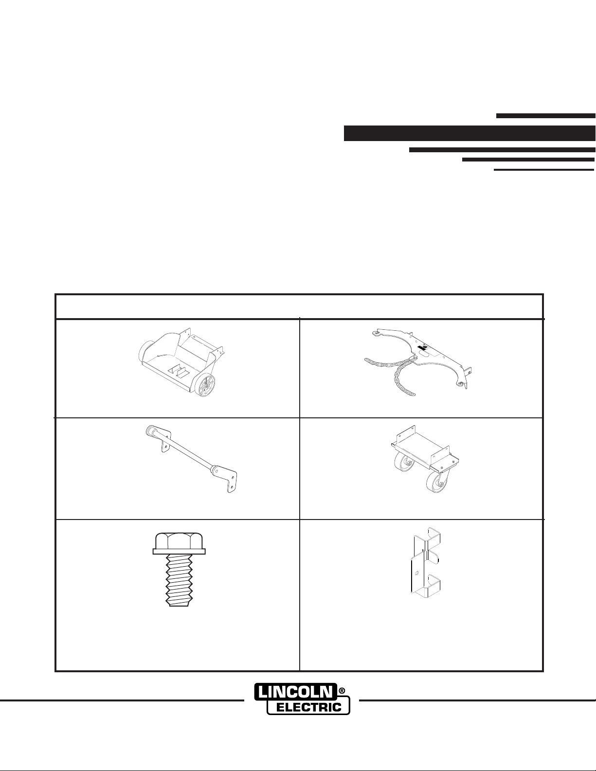
UNPACK THE KIT
Your Undercarriage Kit is a Dual Cylinder kit. Check your Undercarriage Kit for the following.
K1570-1
Dual Cylinder Undercarriage Kit
IM600
June, 2005
WARNING
CYLI
mayexplode
ifdamaged
NDER
Kee
and
pclin
Kee
whe
cha
pc
Ne
re
ine
cl
der
er
lin
Ne
it
dt
ind
t
lif
der
upr
er
ma
Kee
er
tu
tw
igh
all
r
awa
pc
upp
att
be
ch
eld
t
the
ww
ach
dam
lin
rt
cl
er
fr
rl
eld
ed
age
der
ind
wit
ma
ie
ing
d
er
h
rea
awa
ele
ele
ctr
fr
ctrde
ica
mw
lc
eld
irc
ing
uit
Lower Cylinder Support Wheel Assembly Upper Cylinder Support Bracket and Warning Decal
Handle Assembly Caster Wheel Assembly
Cable Retainer (Quantity 2)
(Actual Size)
3/8 - 16 x 1.00 Hex Head Thread Cutting Screw
Cleveland, Ohio 44117-1199 U.S.A. TEL: 216.481.8100 FAX: 216.486.1751 WEB SITE: www.lincolnelectric.com
(Cadium Plated - Quantity 8)
Copyright © 2005 Lincoln Global Inc.
• World's Leader in Welding and Cutting Products •
• Sales and Service through Subsidiaries and Distributors Worldwide •
Page 2
INSTALLATION OF THE K1570-1 DUAL
CYLINDER UNDERCARRIAGE KIT
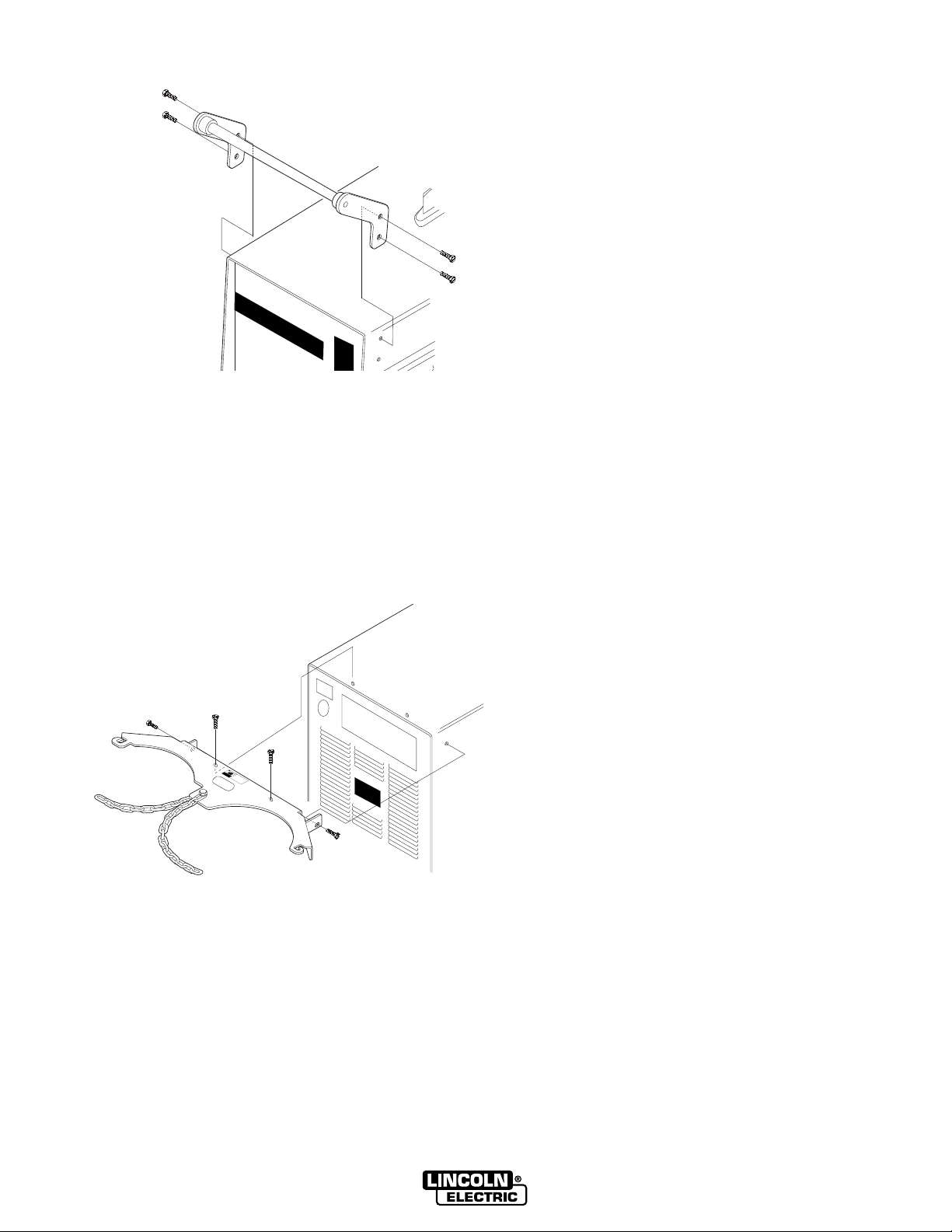
STEP 1. INSTALL THE HANDLE.
a. With the 3/8" nut driver or wrench, remove the
four existing screws from the case sides. Save
the screws to install the handle.
b. Install the handle using the four screws saved
from the previous step.
STEP 2. INSTALL THE UPPER CYLINDER SUPPORT BRACKET.
a. Remove the two existing screws from the case
top and one screw from each case side. Save
the four screws.
b. Position the bracket as shown so that the two
holes in the bracket line up with the two exist-
WARNING
CYLINDER
mayexpl
if
damaged
p
od
y
p
e
v
y
y
v
p
y
p
b
pp
y
y
y
v
y
ing holes in the machine case top.
c. With the 3/8" nut driver or wrench, install the
bracket at the top using the two previously
removed screws. Secure the bracket at the
sides with the two remaining screws. Note
that one of the slots is slightly smaller than the
diameter of the screw to insure proper electrical grounding.
2
Page 3

STEP 3. INSTALL THE CABLE RETAINERS.
a. Locate the existing 1/4-20 screws located half
way up at the back of each case side.
b. Remove these screws with the 3/8 nut-driver
and mount the 2 cable retainers to each case
side as shown. NOTE: The cable retainer
should be oriented as shown when mounting. It should wrap around the case back
corner and lay flat.
STEP 4. INSTALL THE CASTER ASSEMBLY
WARNING
FALLING EQUIPMENT can
cause injury.
• Lift only with equipment of adequate lifting capacity.
• Be sure the machine is stable
when lifting it.
------------------------------------------------------------------
a. Attach the hoist lifting hook to the lift bail of the
machine. Lift the machine to allow enough
clearance to slide the caster assembly into
place.
b. Position the caster assembly at the front of the
machine between the machine base channels.
c. Mount with four 3/8-16x1.00 threading cutting
screws provided with the kit, using two on
each side of the base.
3
Page 4

STEP 5. INSTALL THE LOWER CYLINDER
STEP 5. INSTALL THE LOWER CYLINDER
SUPPORT WHEEL ASSEMBLY
SUPPORT WHEEL ASSEMBLY
WARNING
WARNI
N
G
CYLINDER
mayexp
ifdam
K
e
an
e
aged
p
lod
Ke
d
cy
w
ep
c
h
h
li
N
e
a
e
e
r
c
i
nd
cy
e
y
n
e
l
e
er
N
li
rli
i
i
d
e
t
n
t
n
d
to
oto
up
e
d
ma
e
K
r
era
f
r
e
r
twe
y
or
e
su
i
al
aw
pc
uc
gh
be
p
l
t
ot
ay
p
h
t
o
ta
ld
y
o
w
d
h
l
r
c
c
e
a
e
f
i
t
y
w
h
r
ma
r
r
nd
li
e
ed
om
l
wi
g
li
e
nd
d
e
raw
i
t
d
a
er
n
h
e
r
g
e
el
a
ay
e
s
l
e
ec
c
fr
tr
tr
o
i
m
o
c
d
a
w
e
l
e
l
c
d
i
i
r
n
c
g
u
i
ts
------------------------------------------------------------------
a. Lift the machine to allow enough clearance to
slide the lower cylinder support wheel assembly into place.
a. Position the wheel assembly as shown in the
illustration so that the four holes line up with
the four existing holes in the machine base
channels (two on each side).
b. With the 9/16" socket, 6” x 3/8” extension and
the ratchet, install the wheel assembly to the
sides of the machine base channels using the
remaining four 3/8-16x1.00 thread cutting
screws provided with the kit.
FALLING EQUIPMENT can
cause injury.
• Lift only with equipment of adequate lifting capacity.
• Be sure the machine is stable
when lifting it.
Assembly of the Dual Cylinder Undercarriage Kit
is now complete. Carefully lower the machine to
the floor and detach the hoist.
PARTS LIST
K1570-1
DUAL CYLINDER UNDERCARRIAGE KIT
Item Part No. Description Qty.
No.
1 M17891-1 Lower Cylinder 1
2 S22166-1 Upper Cylinder 1
3 M17889-1 Caster Wheel 1
4 M17130-1 Handle Assembly 1
5 M18239 Cable Retainer 2
6 S9225-53 3/8-16x1.00 Thread Cutting
Support Wheel Assembly
Support Bracket
Assembly
Screw 8
4
 Loading...