

Page 1

WIRE FEEDER
RETURN TO MAIN MENU
OPERATOR'S MANUAL
IM597
MK 091-0414
November 1999
Rev i
For use with Push-Pull Torches Model K1589, K1590, K1591, K1592
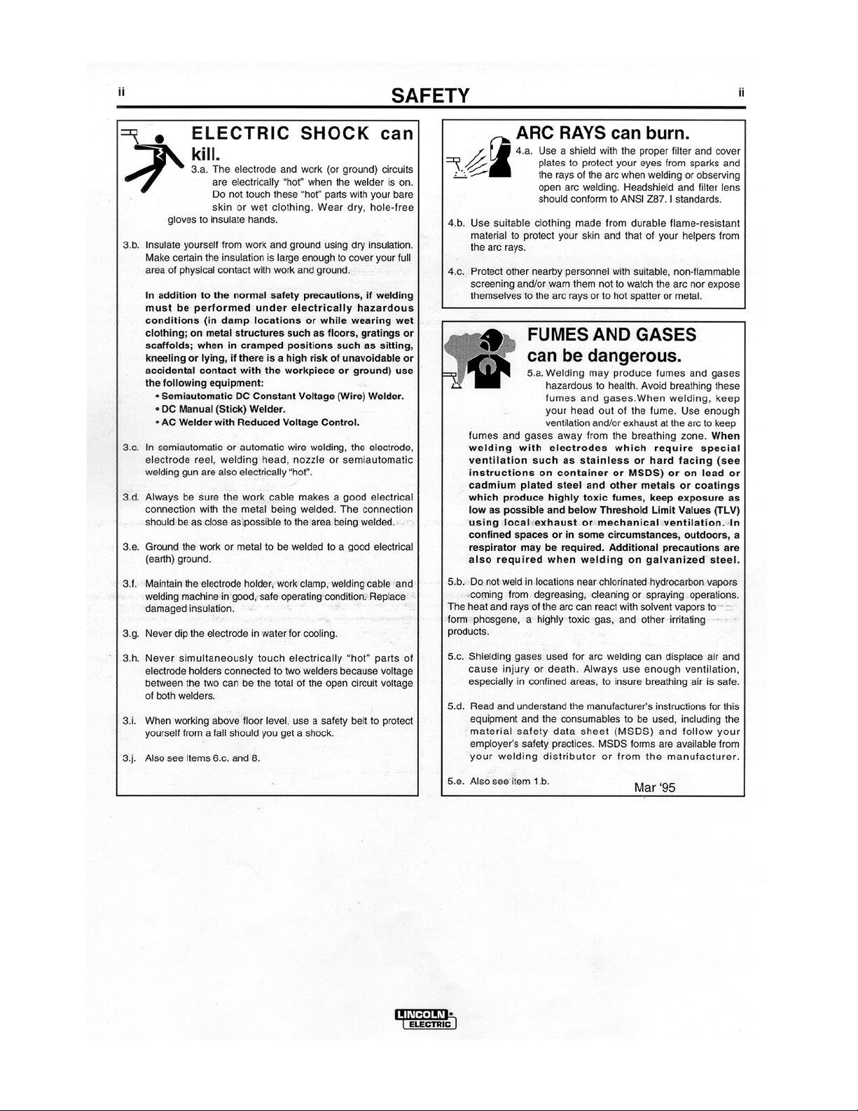
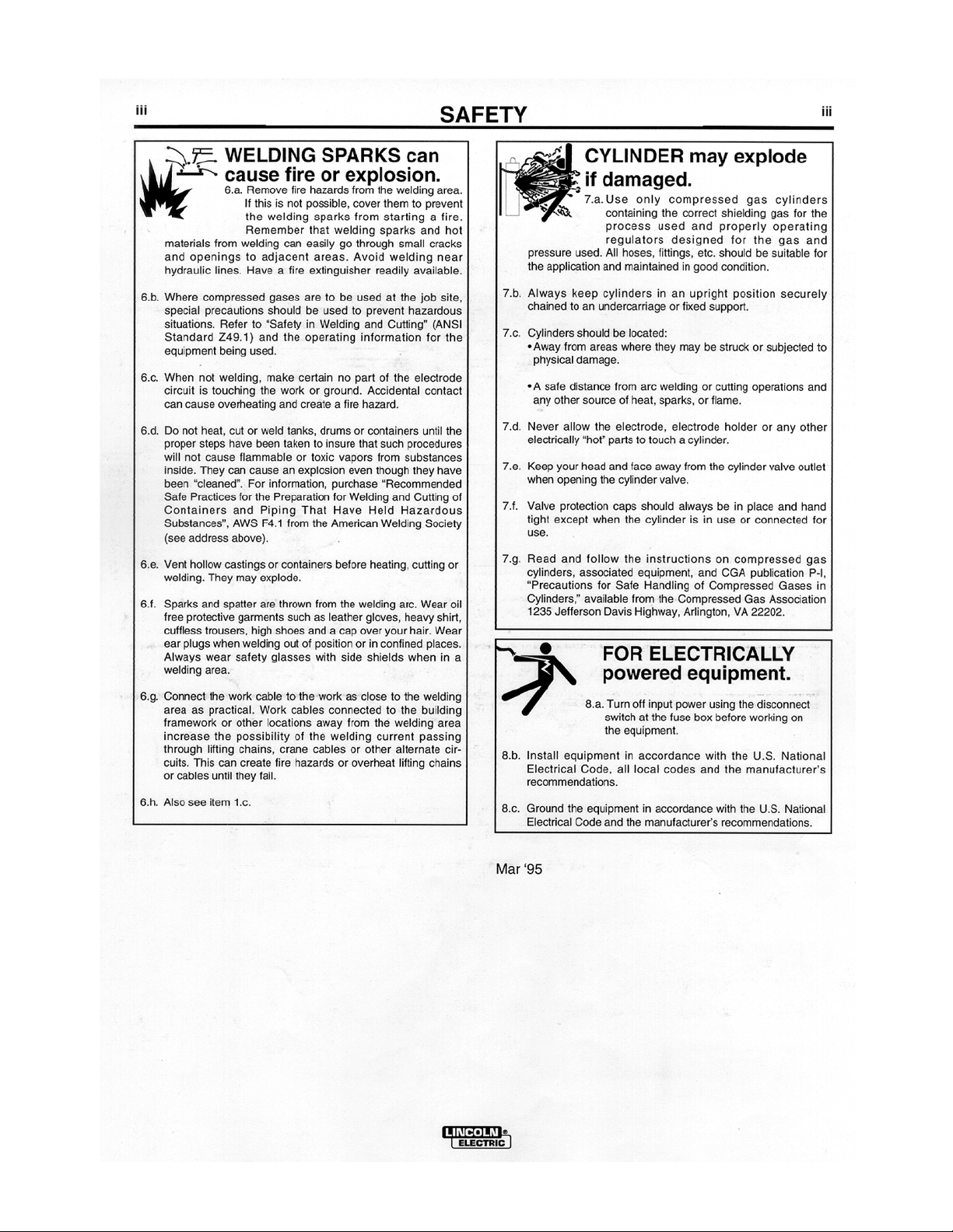
Safety Depends on You
Lincoln arc welding equipment is
designed and built with safety in
mind. However, your overall safety
can be increased by proper
installation...and thoughful operation
on your part. DO NOT INSTALL,
OPERATE OR REPAIR THIS
EQUIPMENT WITHOUT READING
THIS MANUAL AND THE SAFETY
PRECAUTIONS CONTAINED
THROUGHOUT. And, most
importantly, think before you act
and be careful.
Cobramatic
®
World's Leader in Welding and Cutting Products
OPERATOR'S MANUAL
Premier Manufacturer of Industrial Motors
Sales and Service through Subsidiaries and Distibutors Worldwide
Cleveland, Ohio 44117-1199 U.S.A. TEL: 216.481.8100 FAX: 216.486.1751 WEB SITE: www.lincolnelectric.com
Page 2

Page 3
Page 4
Page 5
Page 6
Page 7

THIS PAGE INTENTIONALLY BLANK
K1587-1 Cobramatic® Owner's Manual -
Page 7
Page 8

Table of Contents
Section 1 SPECIFICATIONS ........................................................... 10
Section 2 SUPPORT EQUIPMENT REQUIRED ................................ 10
Section 3 COOLANT RECOMMENDATIONS .................................... 10
Section 4 OPTIONAL ACCESSORIES .............................................. 10
Section 5 INSTALLATION .............................................................. 10
5.1 Location ................................................................................................. 10
5.2 42 VAC Input Power Connections ............................................................. 11
5.3 Posa Start Connection .............................................................................11
Section 6 WIRE THREADING PROCEDURE .................................... 11
6.1 Wire Spool Installation ............................................................................ 11
6.2 Threading Procedure ............................................................................... 11
6.3 Pre-Setting Slave Motor Tension ............................................................... 12
Section 7 OPERATION ................................................................... 12
7.1 General .................................................................................................. 12
7.2 Feeder Controls ...................................................................................... 12
7.3 CV/CC Posa Start Operating Procedure .................................................... 13
Section 8 MAINTENANCE............................................................... 14
8.1 Testing the Torch .................................................................................... 14
8.2 Relay K2 Operation .................................................................................15
8.3 Testing the Input Power Circuits ............................................................... 15
8.4 Testing the Speed Control ........................................................................ 15
MAIN PC BOARD CONNECTIONS ................................... 16
TROUBLE SHOOTING ..................................................... 17
DRAWINGS .................................................................... 18
K1587-1 Wire Feed Cabinet - Exploded View .............................................18
003-2016 Front Panel - Exploded View......................................................20
003-0570 Spindle Brake Assembly - Exploded View .................................... 21
003-1232 Slave Motor Assembly - Exploded View ...................................... 22
Wire Harness for Input Power from Power Source ...................................... 23
Main PC Board Parts Placement................................................................ 24
Front Panel Circuit Board ......................................................................... 26
SCHEMATICS.................................................................. 27
Wiring Schematic .................................................................................... 27
Torch Connections .................................................................................. 28
Block Diagram ........................................................................................ 29
WARRANTY REPAIR STATIONS ..................................... 30
K1587-1 Cobramatic® Owner's Manual -
Page 8
Page 9

THIS PAGE INTENTIONALLY BLANK
K1587-1 Cobramatic® Owner's Manual -
Page 9
Page 10

Section 1 SPECIFICATIONS
Wire Diameter Capacity .................................... .030 - 1/16" ALL Types
Wire Capacity .................................................... 12" Standard
(Insulated or Non-Insulated)
Power Input ....................................................... 42 VAC 50/60 Hz,
............................................................................ 150 Watts Peak (3 amps)
Weight ................................................................ 31 pounds
Shipping Weight ............................................... 36 pounds
For Use with these Lincoln Torches ............... K1589,K1590,K1591,K1592
Section 2 SUPPORT EQUIPMENT REQUIRED
C.V. or C.C. Power Source of Sufficient Capacity for Your Needs.
Regulated Gas Supply and Hoses.
Properly Sized Power Leads from Power Source to Wire Feeder and Ground.
Water Source and Hose Capable of Providing a Minimum of 1 qt/min. at 45
p.s.i. when using water cooled torches.
Section 3 COOLANT RECOMMENDATIONS
1. Use a name-brand additive which does not contain reactive sulphur or
chlorine and does not react with copper, brass, or aluminum.
2. Check coolant periodically to remain within limits of the following:
A. Coolant Flow rate - 1 quart/minute at 45 p.s.i.
B. Resistivity - 10K ohms/centimeter
C. Ph Range - 5.5-8.5
D. Particle Size - .005"
Section 4 OPTIONAL ACCESSORIES
Replacement Plastic Guides for Slave Motor
Lincoln MK Products
Inlet Guide S23980-1 753-0062
Outlet Guide with Knob S23980-2 003-0428
Section 5 INSTALLATION
5.1 LOCATION
The cabinet should be placed in a location where it can be protected from
damage. Lead lengths and accessibility must also be considered when
installing the cabinet.
K1587-1 Cobramatic® Owner's Manual -
Page 10
Page 11

5.2 42 VAC INPUT POWER CONNECTIONS
Your Wire Feeder comes factory ready with a harness to plug directly into all 14 pin
Lincoln Power Sources equipped with 42 VAC auxiliary.
The 42 VAC is connected to the PC Board on terminal strip J5 #1 (neutral) and #2
(hot) and Ground to the Cabinet chassis.
5.3 POSA START CONNECTIONS
Posa Start circuitry aids welding starts by sensing arc establish signals. A
weld ground signal is required for this to circuit to work, which is provided
through the Power Harness to the Power Source and is internally connected
to the P.C. board on terminal strip J6 terminal 2.
Note: Place polarity switch to DCEP. Refer to scetion 7.3 for
power supply settings to insure proper Posa Start operation.
WARNING: TURN THE INPUT POWER TO THE POWER SOURCE OFF
AT THE DISCONNECT SWITCH BEFORE PERFORMING ANY WORK.
Section 6 WIRE THREADING PROCEDURE
6.1 WIRE SPOOL INSTALLATION
Release latches, and open right side door of cabinet.
Remove spool retainer from spindle hub.
Install wire spool onto spindle hub so that wire feeds from bottom of spool
towards slave motor. Make sure that the hole in the spool aligns with pin on
spindle hub. The white dot on the end of the spindle hub will aid in this
alignment.
Replace the spool retainer.
6.2 THREADING PROCEDURE
Place wire size selector switch on front panel to the correct position for the
wire being used.
Loosen end of wire from spool and cut off any kinked or bent portions.
Unreel and straighten out first 6" to 8" of wire.
Release tension from slave motor drive rolls.
Route wire into inlet guide, along drive roll groove, and into wire conduit.
Prevent the wire spool from turning with the palm of the right hand, and at the
same time grasp the slave motor pressure adjusting knob.
Pull the torch trigger and slowly tighten the slave motor pressure adjusting
knob until the slave motor stalls.
CAUTION:
EXCESSIVE DRIVE ROLL TENSION WILL
THAN IMPROVE WIRE FEED PERFORMANCE.
K1587-1 Cobramatic® Owner's Manual -
Page 11
REDUCE RATHER
Page 12

Tighten the torch pressure adjusting knob so the wire will be picked up and
fed through the contact tip. Proper tension is achieved when wire does not
slip if a small amount of pressure is added to the wire as it exits the tip.
6.3 PRE-SETTING SLAVE MOTOR TENSION
All Cobramatics have preset adjusting nuts which enables spools of the same
wire diameter and type to be changed without further pressure adjustment
after initial set-up.
To preset the slave motor tension bottom out the pressure adjusting knob by
turning it completely clockwise.
Prevent the wire spool from turning and using a 9/16" wrench adjust the
preset nut until the slave motor stalls.
Correct pressure will now be achieved by simply bottoming out the pressure
adjusting knob.
6.4 WIRE GUARD
The Cobramatic® Wire Guard is designed to keep the welding wire from
jumping off the spool inside the wire feed cabinet. When the trigger is
released and the brake engages, especially when using a new spool that is
heavier towards the outside, the spool will tend to rotate more against the
spindle drag adjustment.
However since the wire is held by the slave motor it will not move and could
subsequently jump off the back of the spool and become lodged in the brake
mechanism, or jump off the front of the spool and electrically short-out to the
cabinet chassis. The wire guard will keep the wire from doing either.
The wire guard is designed to run inside the spool on top of the wire, and
when the brake is engaged the wire guard will hold the wire onto the spool.
The wire guard is made of a heavy woven nylon material that is resistant to
wear and will not contaminate the surface of the wire.
Section 7 OPERATION
7.1 GENERAL
The AC slave motor in the feeder runs at a fast, constant speed, but has very
low torque. It is always trying to feed more wire than the torch motor wants,
and when the motor gets all it wants, it slows the slave motor preventing a
bird’s nest. Because of the low torque produced by the slave motor, a brake
system is used to prevent wire overrun rather than tension. The drag
adjustment in the spindle is used to keep the wire slightly taut, so it will not
unspool while feeding wire. The 24 VDC torch pull motor is controlled by a
solid state speed control and a potentiometer located in the torch.
7.2 FEEDER CONTROLS
7.2.1 ON/OFF SWITCH
Placing the switch in the “ON” position energizes the feeder circuitry and the
power indicator light.
7.2.2 WIRE SIZE SELECTOR SWITCH
The wire size selector switch changes the torque of the slave motor for the
K1587-1 Cobramatic® Owner's Manual -
Page 12
Page 13

wire you are using. When in the .030-.035 aluminum only position, the slave
motor produces approximately 1 1/2 lbs. inches and approximately 4 1/2 lbs.
inches when in the all other wires position.
(NOTE: Operating the cabinet with the switch in the wrong position will cause
wire feed difficulties.)
7.2.3 POSA START CONTROLS
The Posa Start Run-in Speed Control, located on the front panel, provides
adjustment for slow wire run-in. Once the arc has been established, the wire
feed speed is automatically changed from the slow run-in speed to the
welding speed set on the torch potentiometer.
7.2.4 TORCH AMPHENOL CONNECTORS
The Cobramatic® contains a 7 pin “W” clocked amphenol.
7.2.5 CONDUIT INLET
The Conduit Inlet provides access to the slave motor outlet guide.
7.2.6 GAS INLET
Provides access to the gas fitting inside the cabinet.
7.2.7 POWER INLET
The Power Inlet provides access to the power block inside the cabinet.
7.3 CV/CC POSA START OPERATING PROCEDURE
7.3.1 GENERAL
The Posa Start feature allows the Cobramatic® to be used in combination
with constant current DC welding power sources of open circuit voltage in
excess of 55 volts - also, any constant voltage welding power source capable
of a minimum of 50 amps.
(NOTE: Reverse polarity MUST be used.)
CAUTION:
DO NOT OPERATE A COBRAMATIC® ON A POWER SOURCE HAVING A
HIGH-FREQUENCY STARTING CIRCUIT BEFORE MAKING SURE THAT THE
HIGH-FREQUENCY PORTION OF THE POWER SOURCE IS TURNED OFF.
FAILURE TO TAKE THIS PRECAUTION WILL CAUSE PERMANENT DAMAGE
TO THE POSA START CIRCUITRY.
The Posa Start Run-in Speed Control, located on the front panel, provides
adjustment for slow wire run-in. Once the arc has been established, the wire
feed speed is automatically changed from the slow run-in speed to the
welding speed set on the torch potentiometer.
7.3.2 CV POSA START OPERATION
Attach Cobramatic® to CV power source according to the installation
instructions.
Turn the Cobramatic® to the “ON” position and the Posa Start to the “OFF”
position.
Adjust power source to desired voltage for your weld condition.
Depress gun trigger and adjust wire feed speed at gun to match voltage
setting. If approximate wire feed is not known, it is better to start with excess
wire feed rather than too little, in order to prevent a “burn-back”.
Turn the Posa Start switch to the “ON” position. Press torch trigger and,
using Run-in Speed Control, adjust wire feed rate to approximately 10% of
welding wire speed set at torch.
Strike an arc, and adjust wire feed rate at gun until correct condition is
achieved.
K1587-1 Cobramatic® Owner's Manual -
Page 13
Page 14

7.3.3 CC POSA START OPERATION
Attach the Cobramatic® to a CC power source according to the installation
instructions.
Insure power supply high frequency switch is in the “OFF” position, and
power supply is set to DC reverse polarity.
The power supply contactor should be set to “Remote” or “Tig” and the
amperage control set to “Panel” or “Standard” depending on power supply.
Turn the Cobramatic® power switch to the “ON” position and the Posa Start
switch to the “OFF” position.
Adjust power source to desired amperage for your weld condition.
Press gun trigger and adjust wire feed speed at gun to match current setting.
If approximate wire feed speed is not known, it is better to start with excess
wire feed rather than too little, in order to prevent possible damage to the
contact tip.
Turn Posa Start switch to the “ON” position. Press torch trigger and, using
Run-in Speed Control, adjust wire feed speed to approximately 10% of
welding wire speed set at torch.
Strike an arc; if the wire stubs out, reduce wire feed rate at gun, or increase
amperage setting on power source.
NOTE: Because the Posa Start Run-in Speed always remains a percentage of the
actual welding wire feed rate, the Posa Start run-in speed will always slow down or
speed up proportional to any adjustment you now make at the gun. Therefore, if you
slow down the welding wire feed speed, you will have to increase the Run-in Speed
setting.
Section 8 MAINTENANCE
Maintenance of the torch will normally consist of a general cleaning of the
wire guide system, including tubes, drive rolls, and conduits at regular
intervals.
Remove spatter build-up from inside of nozzles with a hardwood stick.
The only parts on the Cobramatic system that are subject to normal wear are
the conduit, contact tips, gas cups, front body liners, wire guides, drive and
idler rolls. A supply of these parts should be maintained on hand.
If repairs do become necessary, any part can easily be replaced by a qualified
shop maintenance man.
Your Cobramatic® is designed to provide years of reliable service. Normal
wear and component failure may require occasional service.
The number of units in operation and the importance of minimal "down time"
will determine to what extent spare parts should be stocked on hand.
8.1 TESTING THE TORCH
8.1.1 MOTOR CHECK
Remove the amphenol connector from the cabinet.
Using the torch amphenol, check the resistance across pins “A” and
“B”(motor leads). The resistance across the motor should be between 5-10
ohms.
If an open circuit or short exist, check the motor leads and motor
independently.
K1587-1 Cobramatic® Owner's Manual -
Page 14
Page 15

8.1.2 TESTING THE POTENTIOMETER - “W” CLOCKED
Using the torch amphenol, check the resistance across pin “D” (wiper) and
pin “C”. The resistance should vary from 0 - 5K ohms.
Check the resistance across pin “D” (wiper) and pin “G”. The resistance
should vary from 5K - 0 ohms.
8.1.3 TESTING THE MICRO SWITCH
Using the torch amphenol, check for continuity across pins “E” and “F” when
the trigger is pressed.
8.2 RELAY K2 OPERATION
When the torch trigger is pressed, 24VAC is sent to the coil of relay K2.
When K2 is energized, AC is sent to the slave motor, spool brake, and the AC
contactor. Relay K2 is also responsible for sending 24VAC to the speed
control circuit and shorting the torch motor leads together when the trigger is
released for the dynamic braking system. K2 also provides the closing
contactor signal.
8.3 TESTING THE INPUT POWER CIRCUITS
The AC circuits are protected by fuses F2 and F3. If F2 and F3 continually
blow, remove J4 (Brake Solenoid), J7 (slave motor) and J5-3,4 (AC
Contactor) from the P.C. Board. Replace fuse, and retrigger system. If fuse
does not blow; isolate the problem by plugging in J4, J7, and J5-3,4 one at a
time until the fuse blows.
8.4 TESTING THE SPEED CONTROL
NOTE: The torch should be tested first and the amphenol must be connected to the
Cobramatic® to perform this test.
Place a voltmeter across diode D10 and press torch trigger. A reading of 0 24VDC should be observed, as the torch potentiometer varied.
24.024.0
24.0
24.024.0
D10
VDC
+
_
K1587-1 Cobramatic® Owner's Manual -
Page 15
Page 16

MAIN P.C. BOARD CONNECTIONS
Note: For Cabinet Remote Pot Kit, Remove
Jumper from J13-J14. Plug
Remote Pot Kit into J14.
J14
J13
J1
CURRENT SENSOR
(Posa Start)
J2
FRONT PANEL
1 12 2 33 4 4
Control
Cable
LE P/N L10708-1
MK P/N 843-0496
J3
FRONT PANEL
J4
BRAKE SOLENOID
J7
SLAVE MOTOR
J8
J5J6
TRANSFORMER
Input Power - 42VAC
Input Power - 42VAC
Chasis Ground
Closing Contacts Out
Closing Contacts Out
Weld Connection Ref (-)
Not Used
K1587-1 Cobramatic® Owner's Manual -
Page 16
Page 17

TROUBLESHOOTING
TROUBLE CAUSE REMEDY
No wire feed at torch, feeder
not operating, i.e., no slave
motor or brake soleniod.
Brake soleniod inoperative.
No wire feed at torch, feeder
operating properly.
F2 & F3 (MDA7 7A Slow Blow)
fuse in feeder blown.
F1 (4 amp) fuse in feeder blown. Check motor leads for shorts, then
Micro-switch defective/not being
activated. Broken electrical cable.
Relay K2 inoperative. Check/Replace relay K2.
Loose J2, J3, P.C. board
connector
Soleniod defective. Replace soleniod.
Relay K2 inoperative. Check for 42VAC across J4-1 and J4-2
Bad potentiometer. Check potentiometer with meter.
Bad torch motor. Check/Replace motor.
Broken electrical cable. Check motor and potentiometer wires
Bad speed control/PCB. Check/Replace P.C. Board.
Loose or no cable connections. Check all power connections.
Check AC circuit. Replace fuse
replace fuse
Replace switch. Check switch for
operation. Check micro switch wires for
continuity.
Check J2, J3 connectors.
Check relay K2 for AC not present.
for continuity.
Wire feeds, but welding wire
is not energized.
Wire feeds erratically.
Wire feeds one speed only
Wire walks out of drive rolls
Relay K2 not sending contactor
signal.
Contactor control cable loose or in
wrong position.
Welding power source not working
right.
Excessive spool drag pressure. Decrease spool drag pressure inside
Dirty or worn conduit. Blow out or replace conduit.
Incorrect pressure on drive rolls. Adjust pressure at both feeder and
Idler roll stuck. Check for lock washer under idler roll, or
Wrong size contact tip. See contact tip table.
Bad potentiometer. Check with meter.
Broken electrical cable in lead
assy.
Bad speed control. Check/Replace P.C. Board.
Idler roll upside-down. Place groove in idler roll towards top.
Rear wire guide missing. Replace wire guide.
Check/Replace relay K2.
Check power supply owners manual for
location and type of contactor signal
required, i.e. closing contacts or AC.
Check power supply for proper
operation.
hub.
torch.
replace if damaged or worn.
Check potentiometer wires for continuity
or shorts.
K1587-1 Cobramatic® Owner's Manual -
Page 17
Page 18

Exploded View - K1587-1 Wire Feed Cabinet
K1587-1 Cobramatic® Owner's Manual -
Page 18
Page 19

PARTS LIST - K1587-1 Wire Feed Cabinet
No. Qty. Part Number Description
1 1 436-0122 Base, Cabinet, Screened, Lincoln
2 1 438-0019 Cover, Front, PCB, Lincoln
3 14 336-0038 Screw, PH Fil T/B #6-32 x 3/8
4 4 301-0103 Rubber Feet
5 16 333-0043 Washer, Int-Star #6
6 4 336-0006 Screw, PH Fil #6-32 x 1/2
7 6 341-0005 Nut, Hex #6-32
8 2 329-0003 Screw, Hex1/4-20 x 3/4
9 2 332-0009 Washer, Shoulder 0.265 ID
10 1 261-0105 Insulator Power Block
11 1 003-1674 Power Block Assy.
12 1 261-0104 Insulator, Spool
13 2 336-0037 Screw, PH Fil T/B #6-32 x 1/4
14 2 329-0005 Screw, Hex 1/4-20 x 1.00 LG
15 1 261-0372 Insulator, Slave Motor
16 2 331-0005 Washer, Flat 1/4
17 2 333-0009 Washer, Spring Lock 1/4
18 2 341-0010 Nut, Hex 1/4-20
19 1 001-1232 Slave Mtor 42V Assy.
20 1 003-0570 Spindle Brake Assy.
21 1 328-0112 Screw, Socket HD 3/8-16 x 1.00 LG
22 1 003-0784 Pawl Ratchet Assy.
23 1 405-0886 Decal, Warning (T13297)
24 2 327-0012 Screw, ST T/F #6-32 x 1/4 LG
25 1 419-0080 Spring Extension
26 1 003-2095 Brake Solenoid, 42V Assy.
27 1 003-1723 Transformer, 42V Assy.
28 16 336-0005 Screw, PH, Fil, #6-32 x 3/8 LG
29 5 331-0002 Washer, Flat #6
30 4 345-0008 Nut, Self-Locking #6-32
31 1 405-0909 Decal, Electronic Connection
32 1 003-1721 PCB, Main Assy.
33 6 342-0410 Apcer, Stacking #6-32 x 0.534 LG
34 4 336-0039 Screw, PH. Fil. #10-32 x 3/8 LG
35 1 003-2016 Assy, Panel, Front, Lincoln
36 1 351-0752 Bushing Snap 1.12ID, 1.50 Dia Mtg. Hole
37 1 351-0744 Bushing Snap 1.00ID, 1.375 Dia Mtg. Hole
38 4 351-0745 Bushing Snap 15/16ID, 1.125 Dia Mtg. Hole
39 1 351-0082 Cap Plug 7/8 Dia Mtg. Hole
40 1 411-0157 Clamp Cable Strain Rel.
41 1 003-2015 Assy, Doors, Lincoln
42 1 415-0243 Handle Carry
43 4 329-0219 Screw, Hex #10-24 x 1/2 LG
44 4 331-0067 Washer, Flat #10
45 4 333-0007 Washer, Spring Lock #10
46 4 341-0007 Nut, Hex #10-24
47 1 L10708-1 Control Cable, Lincoln 42V
48 1 435-3121 Holder Capacitor
49 0.25ft 261-0446 Mylar Tape
50 4 351-0086 Thread Insert #6-32
51 1 405-0894 Serial Number ID Plate, Lincoln
52 4 351-0089 Thread Insert #10-32
53 2 331-0049 Washer, Flat 1/4
54 4 411-0020 Tie Wrap
55 1 003-1798 External Cap Assy
56 1 351-0758 Bushing, Snap. dia3/4, Black
57 1 301-0087 Wire Guard
K1587-1 Cobramatic® Owner's Manual -
Page 19
Page 20

Exploded View - MK P/N 003-2016 Front Panel
K1587-1 Cobramatic® Owner's Manual -
Page 20
Page 21

Exploded View - MK P/N 003-0570 Spindle Brake Assy.
lbt.0750-BT
serpmoC
.oN .ytQ .oNtraP noitpircseD
11 9650-300yssAgniraeB
31 9500-327ekarBksiD
53 9500-914gnirpSnois
21 5460-734dedloM,eldnipS
63 3600-133talF,rehsaW
73 3603-033.doM8/5x4/1rcSredluohS
41 6621-134gniRpu-kcaB
81 0810-734deifidoM,rehsaW
K1587-1 Cobramatic® Owner's Manual -
111 8100-543gnikcoLfleS,tuN
311 0020-13323/1x8/7x8/3-1talFrehsaW
211 9610-134reniateRloopS
0
91 0320-914gnirpSnoisserpmoC
11 0010-13361/5talF,rehsaW
Page 21
Page 22

Exploded View - MK P/N 001-1232 Slave Motor Assy.
34 3/REF 324-0286 Screw, flat hd 1/4-20 x 3/4
33 3/REF 333-0064 Washer c'sink int star 1/4
32 1/REF 330-0004 Screw, shoulder 1/4 x 3/4
31 1/REF 330-0001 Screw, shoulder 1/4 x 3/8
30 1/REF 501-0207 Idler roll-slave motor
29 1/REF 333-0009 Washer, lock spring 1/4
28 3/REF 331-0044 Washer flat #10
27 1/REF 003-0273 Pressure shaft, knob
26 1/REF 345-0047 Nut, adjust
25 1/REF 419-0211 Spring, comp. 0.62 od x 0.062
24 1/REF 331-0050 Washer, 1/4 id
23 1/REF 413-0209 Idler roll arm
22 1/REF 431-1082 Nut, stop shaft
K1587-1 Cobramatic® Owner's Manual -
21 3/REF 328-0024 Screw, socket hd #8-32 x 3/8
20 1/REF 753-0062 Guide, wire 1/2 dia.
20 1/REF S23980-1* Guide, wire 1/2 dia.
19 1/REF 003-0176 Knob, sub-assy.
18 1/REF 753-0062 Guide, wire outlet 5/8 dia.
18 1/REF S23980-2* Guide, wire outlet 5/8 dia.
17 2/REF 321-0060 Set screw #10-24 x 1/4
16 1/REF 511-0206 Drive roll-slave motor
Page 22
9 1/REF 507-0130 Gear Shaft
15 2/REF 328-0029 Screw, socket hd #8-32 x 1.00
14 2/REF 328-0026 Screw, socket hd #8-32 x 5/8
13 4/REF 333-0006 Washer, lock spring #8
8 1/REF 501-0118 Bearing reduction shaft
12 4/REF 342-0063 Spacer, 1/4 x 0.171 id
11 1/REF 431-0334 Cap
10 1/REF 501-0156 Cap bearing
7 1/REF 431-0347 Gear reduction casting
6 1/REF 261-0213 Gear box insulator
5 1 001-1231 Gear box assy-slave motor
3 1/REF 421-0128 Spring pin 1/16 x 1/4 lg
2 1/REF 507-0128 Hel gear 24p-8t-0.33
1 1 003-1720 Torque motor s/a
Parts List
No. Qty. MK P/N Description
* Lincoln Electric Part Number
Page 23

Wire Harness for Input Power from Power Source
Plug for Lincoln
Power Source
Wires terminated
inside Cobramatic
Cabinet
LE P/N L10708-1 42VAC Interface Cable
(MK P/N 843-0496)
Control Cable Termination Chart
Function Color Code
42 VAC input White I J5-1
42 VAC input Black K J5-2
Posa Start ref. gnd Blue H J6-2
Contactor Red C J6-3
Contactor Orange D J6-4
Ground Green B Chassis
K1587-1 Cobramatic® Owner's Manual -
Lincoln 14 Pin
Plug Receptacle
Page 23
Cobramatic I
Cabinet Terminal
Page 24

MAIN P.C. BOARD
PARTS PLACEMENT
COMPONENTS TO BE REPLACED BY QUALIFIED SERVICE PERSONNEL ONLY.
K1587-1 Cobramatic® Owner's Manual -
Page 24
Page 25

MK P/N 003-1721
MAIN P.C. BOARD
PARTS LIST
COMPONENT # MK P/N DESCRIPTION
K1 ................................. 157-0144...................... RELAY, 5V 500 Ohm 200MA
R3 ................................. 115-0154...................... RESISTOR, carbon .25 watt 6.8K ohm
R4, R5 .......................... 115-0042 ...................... RESISTOR, carbon .50 watt 6.8K ohm
R12, R13 ...................... 115-0120 ...................... RESISTOR, carbon .25 watt 100 ohm
R6 ................................. 115-0122...................... RESISTOR, carbon .25 watt 150 ohm
R7 ................................. 115-0144...................... RESISTOR, carbon .25 watt 10K ohm
R8 ................................. 115-0138...................... RESISTOR, carbon .25 watt 3.3K ohm
R9 ................................. 115-0129...................... RESISTOR, carbon .25 watt 560 ohm
R10 ............................... 115-0136...................... RESISTOR, carbon .25 watt 2.2K ohm
R11 ............................... 115-0141...................... RESISTOR, carbon .25 watt 5.6K ohm
D1 ................................. 124-0002...................... DIODE, 1 amp 800 volts (IN4006)
D6-D10 ......................... 124-0003...................... DIODE, 2.5 amps 1KV (HEP170)
D4 ................................. 124-0011...................... DIODE, zener 1 watt 10 volts (IN4740)
D5 ................................. 124-0012...................... DIODE, zener 1 watt 6.8 volts (IN4736)
Q2 ................................ 122-0011 ...................... TRANSISTOR, NPN 500MA 250 volts (2N5655)
Q3 ................................ 122-0004 ...................... TRANSISTOR, PNP 1 amp 50 volts (2N4249)
Q4 ................................ 122-0013 ...................... TRANSISTOR, unijunction 30 volts (2N2646)
Q5 ................................ 125-0028 ...................... THYRISTOR, 8 amps 400 volts (MCR218-6)
C1, C5, C8, C9 ............. 101-0016 ...................... CAPACITOR, ceramic .01uf 600VDC
C2 ................................. 101-0013...................... CAPACITOR, Poly .047uf 200VDC
C3 ................................. 104-0060...................... CAPACITOR, electrolytic 6.8uf 63 VDC
C4, C6 .......................... 104-0002 ...................... CAPACITOR, tantalum 10uf 20VDC
C7 ................................. 101-0021...................... CAPACITOR, ceramic .047uf 50VDC
RV1, RV5, RV6, RV7 .... 124-0026...................... VARISTOR, 130 volts 10 amps
RV2, RV3, RV4............. 124-0028 ...................... VARISTOR, 56 volts 8 amps
J1 ................................. 153-0866 ...................... CONNECTOR, R/A header 2 pin
J2 ................................. 153-0923 ...................... TERMINAL, header 26 pin
J3 ................................. 153-0842 ...................... TERMINAL, header 10 pin
J4 ................................. 153-0844 ...................... TERMINAL, header 2 pin
J5, J6 ............................ 186-0057...................... TERMINAL, strip 4 pin
J7, J8 ............................ 153-0850...................... CONNECTOR, 6 pin
J13, J14 ........................ 153-0867 ...................... CONNECTOR, R/A header 3 pin
Fuse Holder .................. 152-0008...................... FUSE HOLDER, PC mount
F1 ................................. 151-0043 ...................... FUSE, 3AG 4A 250V
F2, F3 ........................... 151-0021 ...................... FUSE, MDA7 7A Slow Blow
K2 ................................. 157-0022...................... RELAY, 24VAC 4PDT
K2 Socket ..................... 173-0026 ...................... SOCKET, relay 15 pin
Jumper ......................... 003-1307...................... JUMPER CABLE
Clip ............................... 157-0023 ...................... Relay Clip
K1587-1 Cobramatic® Owner's Manual -
Page 25
Page 26

MK P/N 003-2001
FRONT PANEL CIRCUIT BOARD
COMPONENT # MK P/N DESCRIPTION
R1 ................................. 113-0062...................... RESISTOR, wire wound 30 ohm, 8 watt
R2 ................................. 119-0020...................... POTENTIOMETER, 100K ohm
R3 ................................. 115-0037...................... RESISTOR, carbon 2.7K ohm, 1/2 watt
D1 ................................. 124-0045 ...................... LED, green
SW1 ............................. 159-3587...................... SWITCH, DPDT, p.c. mount
SW2 ............................. 159-3586...................... SWITCH, SPDT, p.c. mount
SW3 ............................. 159-3586...................... SWITCH, SPDT p.c. mount
J1 ................................. 153-0842 ...................... HEADER, 10pin, 90 degree
J2 ................................. 153-0924 ...................... HEADER, 26pin, 90 degree
J3 ................................. 153-0860 ...................... HEADER, 8pin, 90 degree
J4 ................................. 153-0860 ...................... HEADER, 8pin, 90 degree
COMPONETS TO BE REPLACED BY QUALIFIED SERVICE PERSONNEL ONLY.
K1587-1 Cobramatic® Owner's Manual -
Page 26
Page 27

COBRAMATIC®
WIRING SCHEMATIC
K1587-1 Cobramatic® Owner's Manual -
Page 27
Page 28

COBRAMATIC®
TORCH CONNECTIONS
K1587-1 Cobramatic® Owner's Manual -
Page 28
Page 29

COBRAMATIC®
BLOCK DIAGRAM
K1587-1 Cobramatic® Owner's Manual -
071-0368
Page 29
Page 30

MK WARRANTY REPAIR STATIONS
for MK Products
ALABAMA
AIRGAS MID-SOUTH
Birmingham, AL
205/251-6835
WELDING ENGINEERING SUPPLY CO.
Prichard, AL
334/457-8681
ARIZONA
PRAXAIR
Phoenix, AZ
602/269-2151
ARKANSAS
APPLIED SERVICES, INC.
Benton, AR
501/860-6464
RELIABLE WELDING REPAIR
Greenwood, AR
501/996-6688
CALIFORNIA
ADVANCED WELDER REPAIR
Commerce, CA
323/263-7383
ARC PRODUCTS
San Diego, CA
619/628-1022
CAL-WELD SUPPLY
Fresno, CA
209/445-0131
EMCO EAST
Concord, CA 94520
PRAXAIR DISTRIBUTION (ARC RENT)
Long Beach, CA
562/427-0099
R. J. KATES
San Diego, CA
619/565-6960
RED-D-ARC, INC.
Carson, CA
COLORADO
INDUSTRIAL GAS PROD. & SUPPLY
Colorado Springs, CO
719/473-1947
WELDERS & EQUIP. SVC. & TESTING
Littleton, CO
303/932-8755
WESTERN SLOPE WELDER REPAIR
Grand Junction, CO
970/243-9616
FLORIDA
A & I SPECIALTIES
Lehigh Acres, FL
941/368-7435
ACTION WELDING SUPPLY
Jacksonville, FL
904/786-2254
AMVEL CORPORATION
Miami, FL
305/592-5678
ELECTRICAL WELDERS SERVICE
Orlando, FL 32808
407/290-9551
HOLOX LTD.
Merrit Island, FL
407/454-4106
HAUN SYSTEMS REPAIR
Orlando, FL
407/872-0011
ROPER ELECTRIC MOTOR SERVICE
Panama City, FL 32405
850/769-6643
SMITTY’S WELDER SERVICE
West Palm Beach, FL
561/845-1224
TRI-GAS
Miami, FL
305/592-3180
SO-CAL AIRGAS
Gardena, CA
310/523-9355
K1587-1 Cobramatic® Owner's Manual -
GEORGIA
MC CULLOUGH ELEC. MOTOR SVC.
Atlanta, GA
404/688-5251
Page 30
Page 31

MK WARRANTY REPAIR STATIONS
for MK Products
B&W INDUSTRIAL SERVICES
Augusta, GA
706/738-8722
IDAHO
NORCO
Boise, ID
208/336-1643
ILLINOIS
BODINE ELECTRIC OF DECATUR
Decatur, IL
217/423-2593
INDUSTRIAL WELDER REBUILDERS
Alsip, IL
708/371-5688
PCI ENERGY SERVICES
Lake Bluff, IL
847/680-8100
RELIABLE EQUIPMENT REPAIR
Hamel, IL
618/633-5000
INDIANA
APCO GAS TECH
Speedway, IN
317/481-4550
EVANSVILLE ARMATURE, INC.
Evansville, IN
812/428-9034
IOWA
CENTRAL STATES AIRGAS
Des Moines, IA
515/266-1111
CEDAR RAPIDS WELDING SUPPLY
Cedar Rapids, IA
319/365-1466
KANSAS
KANOX
Hutchinson, KS
316/665-5551
LOUISIANA
GREENE WELDING SUPPLY
West Monroe, LA
318/340-9206
RED BALL OXYGEN CO.
Shreveport, LA
318/425-3211
MICHIGAN
APEX WELDING GASES & SUPPLY
Muskegon Heights, MI
616/722-3185
WESAR COMPANY
Three Rivers, MI
616/483-9125
MINNESOTA
MINNEAPOLIS OXYGEN CO.
Minneapolis, MN
612/588-8855
OXYGEN SERVICE CO.
St. Paul, MN
612/644-7273
MISSOURI
CEE-KAY SUPPLY, INC.
St. Louis, MO
324/644-3500
P.G. WALKER
Springfield, MO
417/862-1745
NORTH CAROLINA
INDUSTRIAL MAINTENANCE OVERFLOW
Fletcher, NC
704/684-2000
M & L WELDER REPAIR
Asheville, NC
828/250-9353
MACHINE & WELDING SUPPLY CO.
Dunn, NC
910/892-4016
KENTUCKY
GENERAL WELDING PRODUCTS
Louisville, KY
502/635-5218
K1587-1 Cobramatic® Owner's Manual -
NATIONAL WELDERS
High Point, NC
910/882-1110
Page 31
Page 32

MK WARRANTY REPAIR STATIONS
for MK Products
NORTH CAROLINA (contd.)
NATIONAL WELDERS SUPPLY CO.
Charlotte, NC
704/392-7317
OHIO
ALBRIGHT WELDING SUPPLY
Wooster, OH
330/264-2021
ARC EQUIPMENT COMPANY
Struthers, OH 44471
333/750-9353
CnD MACHINE, INC.
Canton, OH 44706
330/478-8811
VALLEY NATIONAL GASES
Lima, OH
419/228-1008
RICK’S WELDER REPAIR SERVICE
Eastlake, OH
440/269-1204
VALLEY NATIONAL GASES
Toledo, OH
419/241-9114
WELDINGHOUSE, INC.
Cleveland, OH
216/524-1955
OKLAHOMA
BILL’S WELDER REPAIR
Oklahoma City, OK
405/232-4799
AIRGAS MID-SOUTH
Tulsa, OK
918/582-0885
J.A. CUNNINGHAM EQUIPMENT, INC.
Philadelphia, PA
215/426-6650
VALLEY NATIONAL GASES
Pittsburgh, PA
412/281-1835
SOUTH CAROLINA
IND’L ELECTRIC REWINDING CO. OF
SUMTER
Sumter, SC
803/773-9366
TENNESSEE
NEXAIR
Memphis, TN
901/523-6821
TEXAS
AIRGAS HOUSTON
Houston, TX
713/462-8027
DENISON OXYGEN
Denison, TX
903/465-3369
RITE-WELD SUPPLY, INC
Fort Worth, TX
817/626-8237
VIRGINIA
NORFOLK WELDERS SUPPLY
Norfolk, VA
804/622-6571
WASHINGTON
A-L WELDING PRODUCTS
Tukwila, WA
425/228-2218
RITE-WELD SUPPLY, INC
dba OKLAHOMA WELDERS SUPPLY
Madill, OK
580/795-5561
PENNSYLVANIA
GEOVIC WELDING SUPPLY
Milton, PA
717/742-9377
K1587-1 Cobramatic® Owner's Manual -
CASCADE AIRGAS/WELDER’S SUPPLY
Seattle, WA
206/224-0433
OXARC, INC
Spokane, WA
509/535-7794
OXYGEN SALES & SERVICE, INC
Tacoma, WA
253/473-2282
Page 32
Page 33

MK WARRANTY REPAIR STATIONS
PACIFIC WELDING SUPPLIES
Tacoma, WA
253/572-5302
PRAXAIR
Seattle, WA
206/624-7033
AMERICAN EQUIPMENT SERVICES
Kent, WA
253/395-9947
WISCONSIN
BENTLEY WELDING SUPPLY
Brookfield, WI
414/938-6365
CANADA
ARC & GENERATOR REPAIR
Garson, Ontario
705/525-2141
for MK Products
INDUSTRIAL ELECTRONIC SERVICES
Calgary, Alberta
403/279-3432
M.R.T. REPAIR CENTER, INC.
Montreal, Québec
514/648-0800
OZARK ELECTRICAL MARINE LTD.
St. John’s Newfoundland
PEEL ENGINES
Mississauga, Ontario
905/670-1535
PROMOTECH électrique, Inc.
Fleurimont, Québec
819/822-2111
WELDERS SUPPLY
Winnipeg, Manitoba
204/772-9476
WELDING WIDE SERVICES, INC.
Brampton, Ontario
905/874-9992
K1587-1 Cobramatic® Owner's Manual -
Page 33
Page 34

Page 35

Page 36

THIS PAGE INTENTIONALLY BLANK
K1587-1 Cobramatic® Owner's Manual -
Page 36
Page 37

Effective April 1, 1998
This warranty supersedes all previous MK Products warranties and is
exclusive, with no other guarantees or warranties expressed or implied.
LIMITED WARRANTY - MK Products,Inc.,Irvine,California warrants
that all new and unused equipment furnished by MK Products is
free from defect in workmanship and material as of the time and
place of delivery by MK Products. No warranty is made by MK
Products with respect to trade accessories or other items
manufactured by others. Such trade accessories and other items
are sold subject to the warranties of their respective manufacturers,
if any.
MK Products’ warranty does not apply to components having
normal useful life of less than one (1) year, such as relay points,
wire conduit, tungsten, and welding torch parts that come in
contact with the welding wire, including nozzles, nozzle insulators,
and contact tips where failure does not result from defect in
workmanship or material.
In the case of MK Products’ breach of warranty or any other duty
with respect to the quality of any goods, the exclusive remedies
therefore shall be at MK Products’ option: (1) repair; (2) replacement;
(3) where authorized in writing by MK Products, the reasonable
cost of repair or replacement at our Irvine, California plant; or (4)
payment of or credit for the purchase price (less reasonable
depreciation based upon actual use) upon return of the goods at
customer’s risk and expense. Upon receipt of notice of apparent
defect or failure, MK Products shall instruct the claimant on the
warranty claim procedures to be followed.
As a matter of general policy only, MK Products may honor an
original user’s warranty claims on warranted equipment in the
event of failure resulting from a defect within the following periods
from the date of delivery of equipment to the original user:
1. Torches and Weldheads ........................................ 1 year
2. All Other Equipment ............................................. 3 years
3. Repairs ................................................................... 90 days
Classification of any item into the foregoing categories shall be at
the sole discretion of MK Products. Notification of any failure must
be made in writing within 30 days of such failure.
A copy of the invoice showing the date of sale must accompany
products returned for warranty repair or replacement.
All equipment returned to MK Products for service must be
properly packaged to guard against damage from shipping. MK
Products will not be responsible for any damages resulting from
shipping.
Normal surface transportation charges (both ways) for products
returned for warranty repair or replacement will be borne by MK
Products, except for products sold to foreign markets.
ANY EXPRESS WARRANTY NOT PROVIDED HEREIN AND
ANY IMPLIED WARRANTY, GUARANTY, OR
REPRESENTATION AS TO PERFORMANCE, AND ANY
REMEDY FOR BREACH OF CONTRACT WHICH, BUT FOR
THIS PROVISION, MIGHT ARISE BY IMPLICATION,
OPERATION OF LAW, CUSTOM OF TRADE, OR COURSE OF
DEALING, INCLUDING ANY IMPLIED WARRANTY OF
MERCHANTABILITY OR OF FITNESS FOR PARTICULAR
PURPOSE, WITH RESPECT TO ANY AND ALL EQUIPMENT
FURNISHED BY MK PRODUCTS, IS EXCLUDED AND
DISCLAIMED BY MK PRODUCTS.
EXCEPT AS EXPRESSLY PROVIDED BY MK PRODUCTS IN
WRITING, MK PRODUCTS ARE INTENDED FOR ULTIMATE
PURCHASE BY COMMERCIAL/INDUSTRIAL USERS AND FOR
OPERATION BY PERSONS TRAINED AND EXPERIENCED IN
THE USE AND MAINTENANCE OF WELDING EQUIPMENT
AND NOT FOR CONSUMERS OR CONSUMER USE. MK
PRODUCTS WARRANTIES DO NOT EXTEND TO, AND NO RESELLER IS AUTHORIZED TO EXTEND MK PRODUCTS’
WARRANTIES TO ANY CONSUMER.
MK Products, Inc.
16882 Armstrong Ave.
Irvine, CA 92606
Tel (949)863-1234
Fax (949)474-1428
World's Leader in Welding and Cutting Products
• Sales and Service through Subsidiaries and Distributors Worldwide •
Cleveland, Ohio 44117-1199 U.S.A. TEL: 216.481.8100 FAX: 216.486.1751 WEB SITE: www.lincolnelectric.com
Premier Manufacturer of Industrial Motors
FORM : LW-8
DATE : April 1, 1998
 Loading...