

Page 1
IM351-D
THELINCOLNELECTRIC CO.
CLEVELAND, OHU.S.A.
Dono
t
touc
h
live
e
le
ctrical
p
arts
ore
lec
t
r
o
dewith
skinorwe
t
clo
t
hin
g
Insula
t
e
y
ou
rselffromwor
k
a
ndgro
und.
A
l
wa
y
swe
a
rd
ryinsulat
i
ng
gloves.
Dono
t
u
s
e
A
Cweld
erif
yourc
lot
h
i
n
g
,
g
lovesor
w
or
k
a
r
e
aisdam
porif
wo
rkingon
,
u
n
d
er
orinsi
d
e
wo
rkplace.
Usethe
followin
g
e
quipme
nt:
S
e
miauto
mat
icDC
con
s
ta
n
tvolta
ge(wir
e)w
e
l
d
er
.
DC
M
anu
a
l(
s
tick
)we
lde
r
A
c
w
eld
erwit
h
red
u
ce
dvolt
a
geco
n
tro
l.
Dono
t
o
p
e
ratewithpa
n
e
lsre
mov
e
d
Disco
nnecti
n
p
u
tp
o
we
rb
e
fo
res
e
rvicing
.
ONLY
Q
U
A
LIF
I
EDPERSONAL
SH
OUL
DINSTALL,
U
SEO
F
SERVI
C
E
T
HI
S
EQUIPMEN
T
.
READ
AN
D
F
O
L
L
O
WTHEMAN
UFAC
T
URE'S
IN
S
TR
U
CTIO
N
S,
EMPLOYER'
SSAFETYPRACTICES AN
DMATERIALSAF
ET
YD
ATA
SHEET
S
(
MSDS)F
OR
C
O
N
SU
MABLES.
SeeAmericanNationalStandardZ 49.1"
SafetyinWeld
i
ngandCutting",publishedb
y
theAmeric
a
nWeldingSoc
iet
y,
55
0LeJeuneRd.,
Mia
mi,Florid
a33126
;
OS
HASaf
etyan
dH
e
athSta
ndar
ds,29CFR191
0A
vailablefromU.S.Gov
e
rn
ment
Pri
n
t
in
gO
ffi
ce,W
as
hington,D.C. 20402. DONO
TR
EMO
VETHIS WARN
ING
AV
E
R
TISE
MENT:
L
ASOUDU
R
E
A
L
'AR
CC
OM
P
O
R
TED
E
S
R
ISQUE
SDE
B
LE
S
SRES
P
U
RL'OPE
R
A
T
EU
R
OULES
PER
SONNE
S
D
A
N
ISLAZO
N
E
DE
TRAV
AI
L.CO
N
SUL
T
ERLANO
T
I
C
E
TECH
N
I
QUE
AV
A
NTU
T
I
LIS
ATIO
N
.
Ke
e
pyo
ur
hea
d
o
u
toffu
m
e
s.
U
see
n
ou
g
hventila
t
iono
rexh
a
usta
t
t
hea
r
c,o
rb
o
th
,
t
ok
ee
p
f
umes
a
ndg
a
se
s
f
r
o
myou
rbrea
t
h
in
gwon
ean
d
ge
n
er
ala
r
e
a.
D
o
n
otw
e
ld
n
ea
r
fla
mmab
l
e
mat
erial.
Don
otw
e
ld
o
nc
o
n
ta
in
er
swh
ic
h
ha
v
eh
el
d
f
la
m
mab
le
mat
eri
al
We
a
re
y
ee
a
ra
ndb
od
yp
r
ot
e
c
t
ion
SERIALNO.
CODENO.
Thismach
ineand theaccesso
riesare cove
redby oneor moreofthe
f
ollowingpatents: United st
a
t
es3
,
806,695;3.975,616; 4,246,463
;
4,247
,
751;Austral
ia467,447; 499,502;517,120; 525,54
1;Brazi
l79,787;
PI
7
,
803,421;PI 7,905
,
509;Canada 96
5,487;
1,
0
41,181;1,093,159
;1,119,674;
Euro
peanPatent 8527(Fran
ce,West
Germany,
Uni
t
e
d
Kingdom,
Netherl
ands,
I
taly,Sweden); France73.01
477;75 34477;7814757lItaly
1,102
,
502;M
exico147
,
019;S.
Korea19064; Swe
den78051
12-5;United
Ki
ngdom1,52
9,
726;1
,
579,700;
W.Germany 2550 278;28 23 2
93.
Ot
herpatents p
endin
g.
RETURN TO MAIN MENU
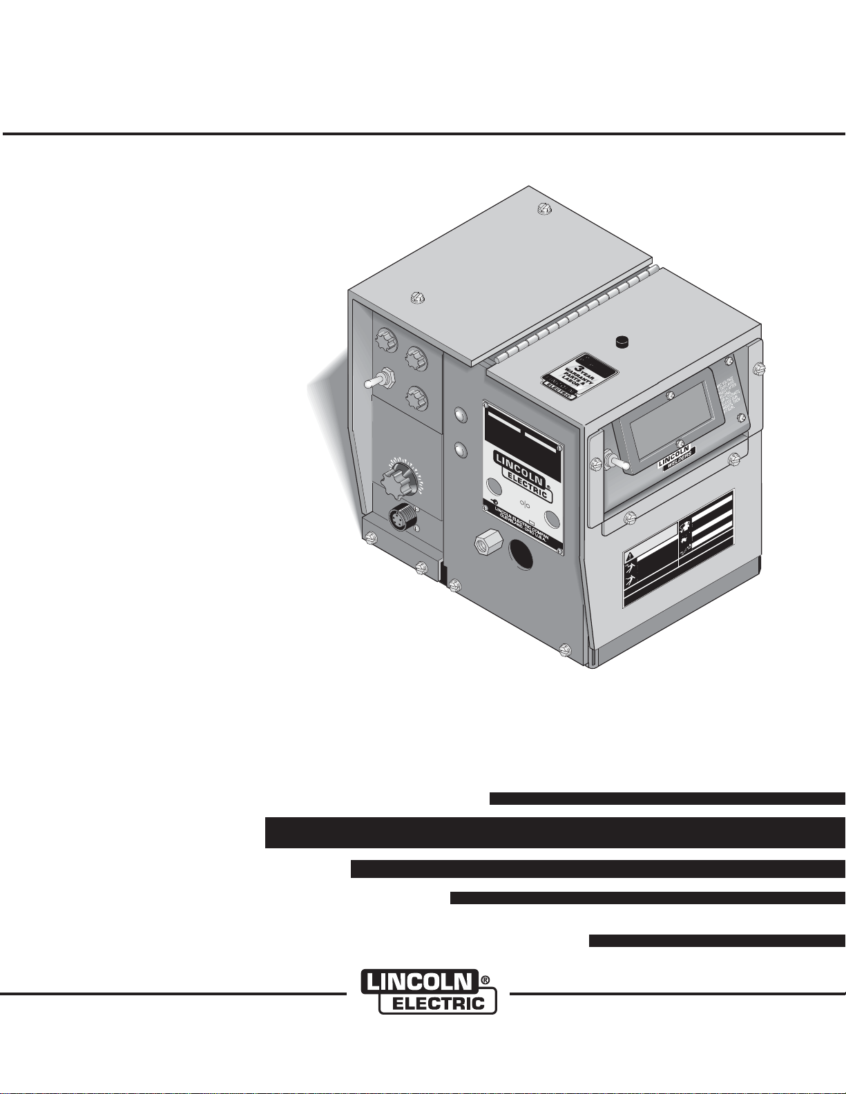
LN-7 and LN-7 GMA Wire Feeders
For machines with code numbers: 9100 and above
Safety Depends on You
Lincoln arc welding and cutting
equipment is designed and built
with safety in mind. However,
your overall safety can be
increased by proper installation ...
and thoughtful operation on your
part. DO NOT INSTALL, OPER-
ATE OR REPAIR THIS EQUIPMENT WITHOUT READING
THIS MANUAL AND THE
SAFETY PRECAUTIONS CONTAINED THROUGHOUT. And,
most importantly, think before you
act and be careful.
LN-7 GMA shown with optional
K417 digital meter kit and K418
GMA timer kit.
(2 and 4 Roll Models)
SERIAL NO.
This mach
f
ollowing patents: U
4,247
ine and the accesso
7
,
,
803,421; PI 7,905
LN-7 GMA CONTROL
WIRE SPEED
INCHE
S PER
3
3
5
MINUTE
0
0
0
4
250
0
0
4
200
5
0
5
1
0
5
0
0
550
100
600
650
700
751; Austral
Euro
Netherl
pean Patent 8527 (Fran
1,102
Ki
,
502; M
ngdom 1,52
Ot
her patents
ands, I
taly, Sweden); France 73.01
exico 147
9,
726; 1
p
endin
nited states 3
ia 467,447;
ries are cove
,
509; Canada
,
8
499,502; 517,120; 525
06,695; 3.975,616; 4,246,46
96
ce,
5,487;
West
,
019; S.
,
579,700; W. Germany 25 50 278;
Germany,
g.
Korea 19064;
LN-7
NEMA EW3
115V, 50/60 HZ AMPS
CODE NO.
red by one or mor
1,041,181; 1,093,159
477; 75 34477;
Uni
Swe
den 780
,
541; Brazi
t
e
d Kingdom,
78 14757l Italy
51
28
June 2013
VOLTS
ELECTRODE
e of
the
3;
l 79,787;
;
1,119,674;
12-5; United
23
2
93.
POLARITY
POSITIVE
PI
NEGATIVE
THE LINCOLN ELECTRIC CO.
kill
trod
c
le
r e
o
.
d
n
rts
OCK can
pa
rou
l
glo
nd g
s.
a
ctrica
ng,
i
e
k
r or
r
th
WARNING
el
glove
lo
wo
g
ing
c
r
h
live
unde
t
tin
u
n,
la
ch
yo
u
f from
o
clo
l
t
su
o
g
if
ELECTRIC SH
t
r
t
ge (wir
o
urse
ry in
lde
lta
o
or we
d
e
r
y
vo
Do n
a
e
t
t
n
C w
skin
a
ment:
l
or if workin
ontrol.
A
ta
s we
s
c
p
e
y
e
s
Insu
d
g.
u
con
wa
e
t
er
l
tag
g equip
l
ld
A
n
is dam
DC
mov
wi
a
ic
ervicin
e
Do no
r
s
ollo
a
f
rkplace.
ick) we
F
t
mat
duced vo
s
ore
wo
f
anels re
l (
e
re
p
a
h
SE O
U
miauto
ET
Use the
URE'S
anu
e
T
with
S
M
er wit
e
power b
AC
t
TALL,
eld
rat
F
DC
u
S
e
U
w
p
IN
c
inp
o
A
t
D
MATERIAL SAF
nnect
OUL
Do no
THE MAN
D
SH
HA
Disco
LOW
L
OS
O
;
SONAL
F
R
D
AN
PRACTICES AN
ED PE
I
a 33126
LIF
MABLES.
A
READ
.
U
T
SU
SAFETY
Q
N
S
O
C
mi, Florid
ONLY
OR
Mia
F
EQUIPMEN
hington, D.C. 20402. DO
EMPLOYER'
Rd.,
as
MSDS)
(
ce, W
ffi
See American National Standard Z 49.1 "Safety in Weld
0 Le Jeune
g O
in
55
t
n
Pri
CLEVELAND, OH U.S.A.
S.
OTHER
F &
RSEL
e
U
b
alth
OTECT YO
,
d
oth
PR
an
r he
e
b
r
o
c,
won
r
g
a
ND GASES can
in
he
th
A
t
t
a
s.
t
brea
e
s
r
u
m
S WARNING,
a
se
fu
you
u
of
m
exh
t
r
THI
o
u
r
o
f
gerous to you
FUMES
s
d o
ion
t
se
a
hea
g
dan
READ
ur
nd
ventila
a
yo
h
p
g
le
e
ou
Ke
umes
n
RKS can ca
mab
a.
e
e
p f
m
r
A
se
la
ee
f
U
al a
n.
ld
o k
ial.
SP
t
e
er
h
n
er
t
e
ge
v
ma
ha
le
h
s and
ic
wh
mmab
s
explosio
er
fla
r
in
WELDING
E
DE
ta
nea
D
n
o
ld
c
e
n
fire or
w
o
.
injure eye
ot
ld
N
n
ZONE
e
o
w
D
LA
ot
al
ATIO
n
ES RISQUES
IS
can
S
eri
Do
y,
mat
TE D
TILI
ction
DAN
iet
e
R
S
ot
O
r
P
NT U
y p
in.
A
ent
od
OM
b
m
C
SONNE
6
nd
rn
C
ARC RAYS
a
e
r
rn sk
with
a
QUE AV
I
PER
'AR
e
MENT: L
WARN
U
P
N
ng", published
ds, 29 CFR 191
619
e
L
1
bu
y
A
re
E
a
n Welding Soc
R
a
OULES
TECHN
We
R
E
VM M
C
I
UDU
EU
T
O
T
A
R
A S
LA NO
the Americ
ER
T
y
R L'OPE
b
vailable from U.S. Gov
A
SUL
0
G
N
I
e
k
r
o
w
r
o
s
ve
nside
i
r.
lde
e
w
)
TISE
e
R
E
SRES
S
L. CO
AV
AI
LE
B
TRAV
S
S,
HI
N
T
S
E
C
CTIO
U
ndar
SHEET
TR
S
SERVI
IN
ATA
ng and Cutti
D
i
Y
ath Sta
e
d H
VE THIS
EMO
ety an
T R
Saf
NO
Cleveland, Ohio 44117-1199 U.S.A. TEL: 216.481.8100 FAX: 216.486.1751 WEB SITE: www.lincolnelectric.com
OPERATORʼS MANUAL
• World's Leader in Welding and Cutting Products •
Copyright © Lincoln Global Inc.
• Sales and Service through Subsidiaries and Distributors Worldwide •
Page 2

i
SAFETY
i
WARNING
CALIFORNIA PROPOSITION 65 WARNINGS
Diesel engine exhaust and some of its constituents
are known to the State of California to cause cancer, birth defects, and other reproductive harm.
The Above For Diesel Engines
ARC WELDING CAN BE HAZARDOUS. PROTECT YOURSELF AND OTHERS FROM POSSIBLE SERIOUS INJURY OR DEATH.
KEEP CHILDREN AWAY. PACEMAKER WEARERS SHOULD CONSULT WITH THEIR DOCTOR BEFORE OPERATING.
Read and understand the following safety highlights. For additional safety information, it is strongly recommended that you
purchase a copy of “Safety in Welding & Cutting - ANSI Standard Z49.1” from the American Welding Society, P.O. Box
351040, Miami, Florida 33135 or CSA Standard W117.2-1974. A Free copy of “Arc Welding Safety” booklet E205 is available
from the Lincoln Electric Company, 22801 St. Clair Avenue, Cleveland, Ohio 44117-1199.
BE SURE THAT ALL INSTALLATION, OPERATION, MAINTENANCE AND REPAIR PROCEDURES ARE
PERFORMED ONLY BY QUALIFIED INDIVIDUALS.
The engine exhaust from this product contains
chemicals known to the State of California to cause
cancer, birth defects, or other reproductive harm.
The Above For Gasoline Engines
FOR ENGINE
powered equipment.
1.a. Turn the engine off before troubleshooting and maintenance
work unless the maintenance work requires it to be running.
____________________________________________________
1.b.Operate engines in open, well-ventilated
areas or vent the engine exhaust fumes
outdoors.
____________________________________________________
1.c. Do not add the fuel nea r a n o pen flame
welding arc or when the engine is running.
Stop the engine and allow it to cool before
refueling to prevent spilled fuel from vaporizing on contact with hot engine parts and
igniting. Do not spill fuel when filling tank. If
fuel is spilled, wipe it up and do not start
engine until fumes have been eliminated.
____________________________________________________
1.d. Keep all equipment safety guards, covers
and devices in position and in good
repair.Keep hands, hair, clothing and tools
away from V-belts, gears, fans and all other
moving parts when starting, operating or
repairing equipment.
____________________________________________________
1.e. In some cases it may be necessary to remove safety
guards to perform required maintenance. Remove
guards only when necessary and replace them when the
maintenance requiring their removal is complete.
Always use the greatest care when working near moving
parts.
___________________________________________________
1.f. Do not put your hands near the engine fan. Do not attempt
to override the governor or idler by pushing on the throttle
control rods while the engine is running.
___________________________________________________
1.g. To prevent accidentally starting gasoline engines while
turning the engine or welding generator during maintenance
work, disconnect the spark plug wires, distributor cap or
magneto wire as appropriate.
1.h. To avoid scalding, do not remove the
radiator pressure cap when the engine is
hot.
ELECTRIC AND
MAGNETIC FIELDS
may be dangerous
2.a. Electric current flowing through any conductor causes
localized Electric and Magnetic Fields (EMF). Welding
current creates EMF fields around welding cables and
welding machines
2.b. EMF fields may interfere with some pacemakers, and
welders having a pacemaker should consult their physician
before welding.
2.c. Exposure to EMF fields in welding may have other health
effects which are now not known.
2.d. All welders should use the following procedures in order to
minimize exposure to EMF fields from the welding circuit:
2.d.1.
Route the electrode and work cables together - Secure
them with tape when possible.
2.d.2. Never coil the electrode lead around your body.
2.d.3. Do not place your body between the electrode and
work cables. If the electrode cable is on your right
side, the work cable should also be on your right side.
2.d.4. Connect the work cable to the workpiece as close as
possible to the area being welded.
2.d.5. Do not work next to welding power source.
Page 3
ii
SAFETY
ii
ELECTRIC SHOCK can
kill.
3.a. The electrode and work (or ground) circuits
are electrically “hot” when the welder is on.
Do not touch these “hot” parts with your bare
skin or wet clothing. Wear dry, hole-free
gloves to insulate hands.
3.b. Insulate yourself from work and ground using dry insulation.
Make certain the insulation is large enough to cover your full
area of physical contact with work and ground.
In addition to the normal safety precautions, if welding
must be performed under electrically hazardous
conditions (in damp locations or while wearing wet
clothing; on metal structures such as floors, gratings or
scaffolds; when in cramped positions such as sitting,
kneeling or lying, if there is a high risk of unavoidable or
accidental contact with the workpiece or ground) use
the following equipment:
• Semiautomatic DC Constant Voltage (Wire) Welder.
• DC Manual (Stick) Welder.
• AC Welder with Reduced Voltage Control.
3.c. In semiautomatic or automatic wire welding, the electrode,
electrode reel, welding head, nozzle or semiautomatic
welding gun are also electrically “hot”.
3.d. Always be sure the work cable makes a good electrical
connection with the metal being welded. The connection
should be as close as possible to the area being welded.
3.e. Ground the work or metal to be welded to a good electrical
(earth) ground.
3.f.
Maintain the electrode holder, work clamp, welding cable and
welding machine in good, safe operating condition. Replace
damaged insulation.
3.g. Never dip the electrode in water for cooling.
3.h. Never simultaneously touch electrically “hot” parts of
electrode holders connected to two welders because voltage
between the two can be the total of the open circuit voltage
of both welders.
3.i. When working above floor level, use a safety belt to protect
yourself from a fall should you get a shock.
3.j. Also see Items 6.c. and 8.
ARC RAYS can burn.
4.a. Use a shield with the proper filter and cover
plates to protect your eyes from sparks and
the rays of the arc when welding or observing
open arc welding. Headshield and filter lens
should conform to ANSI Z87. I standards.
4.b. Use suitable clothing made from durable flame-resistant
material to protect your skin and that of your helpers from
the arc rays.
4.c. Protect other nearby personnel with suitable, non-flammable
screening and/or warn them not to watch the arc nor expose
themselves to the arc rays or to hot spatter or metal.
FUMES AND GASES
can be dangerous.
5.a. Welding may produce fumes and gases
hazardous to health. Avoid breathing these
fumes and gases. When welding, keep
your head out of the fume. Use enough
ventilation and/or exhaust at the arc to keep
fumes and gases away from the breathing zone. When
welding with electrodes which require special
ventilation such as stainless or hard facing (see
instructions on container or MSDS) or on lead or
cadmium plated steel and other metals or coatings
which produce highly toxic fumes, keep exposure as
low as possible and within applicable OSHA PEL and
ACGIH TLV limits using local exhaust or mechanical
ventilation. In confined spaces or in some circumstances, outdoors, a respirator may be required.
Additional precautions are also required when welding
on galvanized steel.
5. b. The operation of welding fume control equipment is affected
by various factors including proper use and positioning of
the equipment, maintenance of the equipment and the specific welding procedure and application involved. Worker
exposure level should be checked upon installation and
periodically thereafter to be certain it is within applicable
OSHA PEL and ACGIH TLV limits.
5.c.
Do not weld in locations near chlorinated hydrocarbon
coming from degreasing, cleaning or spraying operations.
The heat and rays of the arc can react with solvent vapors
form phosgene, a highly toxic gas, and other irritating products.
5.d. Shielding gases used for arc welding can displace air and
cause injury or death. Always use enough ventilation,
especially in confined areas, to insure breathing air is safe.
vapors
to
5.e. Read and understand the manufacturer’s instructions for this
equipment and the consumables to be used, including the
material safety data sheet (MSDS) and follow your
employer’s safety practices. MSDS forms are available from
your welding distributor or from the manufacturer.
5.f. Also see item 1.b.
Page 4
iii
SAFETY
iii
WELDING and CUTTING
SPARKS can
cause fire or explosion.
6.a.
Remove fire hazards from the welding area.
If this is not possible, cover them to prevent
Remember that welding sparks and hot
materials from welding can easily go through small cracks
and openings to adjacent areas. Avoid welding near
hydraulic lines. Have a fire extinguisher readily available.
6.b. Where compressed gases are to be used at the job site,
special precautions should be used to prevent hazardous
situations. Refer to “Safety in Welding and Cutting” (ANSI
Standard Z49.1) and the operating information for the
equipment being used.
6.c. When not welding, make certain no part of the electrode
circuit is touching the work or ground. Accidental contact
can cause overheating and create a fire hazard.
6.d. Do not heat, cut or weld tanks, drums or containers until the
proper steps have been taken to insure that such procedures
will not cause flammable or toxic vapors from substances
inside. They can cause an explosion even
been “cleaned”. For information, purchase “Recommended
Safe Practices for the
Containers and Piping That Have Held Hazardous
Substances”, AWS F4.1 from the American Welding Society
(see address above).
6.e. Vent hollow castings or containers before heating, cutting or
welding. They may explode.
Sparks and spatter are thrown from the welding arc. Wear oil
6.f.
free protective garments such as leather gloves, heavy shirt,
cuffless trousers, high shoes and a cap over your hair. Wear
ear plugs when welding out of position or in confined places.
Always wear safety glasses with side shields when in a
welding area.
6.g. Connect the work cable to the work as close to the welding
area as practical. Work cables connected to the building
framework or other locations away from the welding area
increase the possibility of the welding current passing
through lifting chains, crane cables or other alternate circuits. This can create fire hazards or overheat lifting chains
or cables until they fail.
6.h. Also see item 1.c.
the welding sparks from starting a fire.
though
they have
Preparation
for Welding and Cutting of
CYLINDER may explode
if damaged.
7.a. Use o nly c omp r essed gas cylinders
containing the correct shielding gas for the
process used and properly operating
regulators designed for the gas and
pressure used. All hoses, fittings, etc. should be suitable for
the application and maintained in good condition.
7.b. Always keep cylinders in an upright position securely
chained to an undercarriage or fixed support.
7.c. Cylinders should be located:
• Away from areas where they may be struck or subjected to
physical damage.
• A safe distance from arc welding or cutting operations and
any other source of heat, sparks, or flame.
7.d. Never allow the electrode, electrode holder or any other
electrically “hot” parts to touch a cylinder.
7.e. Keep your head and face away from the cylinder valve outlet
when opening the cylinder valve.
7.f. Valve protection caps should always be in place and hand
tight except when the cylinder is in use or connected for
use.
7.g. Re ad and fo llow t he ins tr uctio ns on c om pressed gas
cylinders, associated equipment, and CGA publication P-l,
“Precautions for Safe Handling of Compressed Gases in
Cylinders,” available from the Compressed Gas Association
1235 Jefferson Davis Highway, Arlington, VA 22202.
FOR ELECTRICALLY
powered equipment.
8.a. Turn off input power using the disconnect
switch at the fuse box before working on
the equipment.
8.b. Ins tall equipment in accordance with the U.S. National
Electrical Code, all local codes and the manufacturer’s
recommendations.
8.c. Ground the equipment in accordance with the U.S. National
Electrical Code and the manufacturer’s recommendations.
6.I. Read and follow NFPA 51B “ Standard for Fire Prevention
During Welding, Cutting and Other Hot Work”, available
from NFPA, 1 Batterymarch Park, PO box 9101, Quincy, Ma
022690-9101.
6.j. Do not use a welding power source for pipe thawing.
Refer to http://www.lincolnelectric.com/safety for additional safety information.
Page 5
iv
SAFETY
iv
PRÉCAUTIONS DE SÛRETÉ
Pour votre propre protection lire et observer toutes les instructions et les précautions de sûreté specifiques qui parraissent
dans ce manuel aussi bien que les précautions de sûreté
générales suivantes:
Sûreté Pour Soudage A LʼArc
1. Protegez-vous contre la secousse électrique:
a. Les circuits à lʼélectrode et à la piéce sont sous tension
quand la machine à souder est en marche. Eviter toujours
tout contact entre les parties sous tension et la peau nue
ou les vétements mouillés. Porter des gants secs et sans
trous pour isoler les mains.
b. Faire trés attention de bien sʼisoler de la masse quand on
soude dans des endroits humides, ou sur un plancher
metallique ou des grilles metalliques, principalement dans
les positions assis ou couché pour lesquelles une
grande partie du corps peut être en contact avec la
masse.
c. Maintenir le porte-électrode, la pince de masse, le câble
de soudage et la machine à souder en bon et sûr état
defonctionnement.
d.Ne jamais plonger le porte-électrode dans lʼeau pour le
refroidir.
e. Ne jamais toucher simultanément les parties sous tension
des porte-électrodes connectés à deux machines à souder parce que la tension entre les deux pinces peut être le
total de la tension à vide des deux machines.
f. Si on utilise la machine à souder comme une source de
courant pour soudage semi-automatique, ces precautions
pour le porte-électrode sʼapplicuent aussi au pistolet de
soudage.
5. Toujours porter des lunettes de sécurité dans la zone de
soudage. Utiliser des lunettes avec écrans lateraux dans les
zones où lʼon pique le laitier.
6. Eloigner les matériaux inflammables ou les recouvrir afin de
prévenir tout risque dʼincendie dû aux étincelles.
7. Quand on ne soude pas, poser la pince à une endroit isolé de
la masse. Un court-circuit accidental peut provoquer un
échauffement et un risque dʼincendie.
8. Sʼassurer que la masse est connectée le plus prés possible
de la zone de travail quʼil est pratique de le faire. Si on place
la masse sur la charpente de la construction ou dʼautres
endroits éloignés de la zone de travail, on augmente le risque
de voir passer le courant de soudage par les chaines de levage, câbles de grue, ou autres circuits. Cela peut provoquer
des risques dʼincendie ou dʼechauffement des chaines et des
câbles jusquʼà ce quʼils se rompent.
9. Assurer une ventilation suffisante dans la zone de soudage.
Ceci est particuliérement important pour le soudage de tôles
galvanisées plombées, ou cadmiées ou tout autre métal qui
produit des fumeés toxiques.
10. Ne pas souder en présence de vapeurs de chlore provenant
dʼopérations de dégraissage, nettoyage ou pistolage. La
chaleur ou les rayons de lʼarc peuvent réagir avec les
vapeurs du solvant pour produire du phosgéne (gas fortement toxique) ou autres produits irritants.
11. Pour obtenir de plus amples renseignements sur la sûreté,
voir le code “Code for safety in welding and cutting” CSA
Standard W 117.2-1974.
2. Dans le cas de travail au dessus du niveau du sol, se protéger contre les chutes dans le cas ou on recoit un choc. Ne
jamais enrouler le câble-électrode autour de nʼimporte quelle
partie du corps.
3. Un coup dʼarc peut être plus sévère quʼun coup de soliel,
donc:
a. Utiliser un bon masque avec un verre filtrant approprié
ainsi quʼun verre blanc afin de se protéger les yeux du
rayonnement de lʼarc et des projections quand on soude
ou quand on regarde lʼarc.
b. Porter des vêtements convenables afin de protéger la
peau de soudeur et des aides contre le rayonnement de
lʻarc.
c. Protéger lʼautre personnel travaillant à proximité au
soudage à lʼaide dʼécrans appropriés et non-inflammables.
4. Des gouttes de laitier en fusion sont émises de lʼarc de
soudage. Se protéger avec des vêtements de protection
libres de lʼhuile, tels que les gants en cuir, chemise épaisse,
pantalons sans revers, et chaussures montantes.
PRÉCAUTIONS DE SÛRETÉ POUR
LES MACHINES À SOUDER À
TRANSFORMATEUR ET À
REDRESSEUR
1. Relier à la terre le chassis du poste conformement au code
de lʼélectricité et aux recommendations du fabricant. Le dispositif de montage ou la piece à souder doit être branché à
une bonne mise à la terre.
2. Autant que possible, Iʼinstallation et lʼentretien du poste
seront effectués par un électricien qualifié.
3. Avant de faires des travaux à lʼ interieur de poste, la
debrancher à lʼinterrupteur à la boite de fusibles.
4. Garder tous les couvercles et dispositifs de sûreté à leur
place.
Page 6
Thank You
vv
for selecting a QUALITY product by Lincoln Electric. We want you
to take pride in operating this Lincoln Electric Company product
••• as much pride as we have in bringing this product to you!
The business of The Lincoln Electric Company is manufacturing and selling high quality welding equipment, consumables, and cutting equipment. Our challenge is to meet the needs of our customers and to exceed their expectations. On occasion, purchasers may ask Lincoln
Electric for advice or information about their use of our products. We respond to our customers based on the best information in our possession at that time. Lincoln Electric is not in a position to warrant or guarantee such advice, and assumes no liability, with respect to such information or advice. We expressly disclaim any warranty of any kind, including any warranty of fitness for any customer’s particular purpose,
with respect to such information or advice. As a matter of practical consideration, we also cannot assume any responsibility for updating or
correcting any such information or advice once it has been given, nor does the provision of information or advice create, expand or alter any
warranty with respect to the sale of our products.
Lincoln Electric is a responsive manufacturer, but the selection and use of specific products sold by Lincoln Electric is solely within the control
of, and remains the sole responsibility of the customer. Many variables beyond the control of Lincoln Electric affect the results obtained in
applying these types of fabrication methods and service requirements.
Subject to Change – This information is accurate to the best of our knowledge at the time of printing. Please refer to www.lincolnelectric.com
for any updated information.
CUSTOMER ASSISTANCE POLICY
Please Examine Carton and Equipment For Damage Immediately
When this equipment is shipped, title passes to the purchaser upon receipt by the carrier. Consequently, Claims
for material damaged in shipment must be made by the purchaser against the transportation company at the
time the shipment is received.
Please record your equipment identification information below for future reference. This information can be
found on your machine nameplate.
Product _________________________________________________________________________________
Model Number ___________________________________________________________________________
Code Number or Date Code_________________________________________________________________
Serial Number____________________________________________________________________________
Date Purchased___________________________________________________________________________
Where Purchased_________________________________________________________________________
Whenever you request replacement parts or information on this equipment, always supply the information you
have recorded above. The code number is especially important when identifying the correct replacement parts.
On-Line Product Registration
- Register your machine with Lincoln Electric either via fax or over the Internet.
• For faxing: Complete the form on the back of the warranty statement included in the literature packet
accompanying this machine and fax the form per the instructions printed on it.
• For On-Line Registration: Go to our
“Product Registration”. Please complete the form and submit your registration.
Read this Operators Manual completely before attempting to use this equipment. Save this manual and keep it
handy for quick reference. Pay particular attention to the safety instructions we have provided for your protection.
The level of seriousness to be applied to each is explained below:
WEB SITE at www.lincolnelectric.com. Choose “Quick Links” and then
WARNING
This statement appears where the information must be followed exactly to avoid serious personal injury or loss of life.
CAUTION
This statement appears where the information must be followed to avoid minor personal injury or damage to this equipment.
LN-7 & LN-7 GMA
Page 7

TABLE OF CONTENTS
Page
Safety . . . . . . . . . . . . . . . . . . . . . . . . . . . . . . . . . . . . . . . . . . . . . . . . . . . . . . . i-iv
Installation . . . . . . . . . . . . . . . . . . . . . . . . . . . . . . . . . . . . . . . . . . . . . . . . . . . Section A
Technical Specifications . . . . . . . . . . . . . . . . . . . . . . . . . . . . . . . . . . . . . . A-1
Mounting Location . . . . . . . . . . . . . . . . . . . . . . . . . . . . . . . . . . . . . . . . . . A-2
Machine Grounding . . . . . . . . . . . . . . . . . . . . . . . . . . . . . . . . . . . . . . . . . A-2
Input Cable Connections . . . . . . . . . . . . . . . . . . . . . . . . . . . . . . . . . . . . . A-2
Work Cable . . . . . . . . . . . . . . . . . . . . . . . . . . . . . . . . . . . . . . . . . . . . . . . . A-21
Gun and Cable Assemblies . . . . . . . . . . . . . . . . . . . . . . . . . . . . . . . . . . . A-21
Gun Cable Connections . . . . . . . . . . . . . . . . . . . . . . . . . . . . . . . . . . . . . . A-21
Water Connections (For Water Cooled Guns) . . . . . . . . . . . . . . . . . . . . . A-22
Shielding Gas Hookup . . . . . . . . . . . . . . . . . . . . . . . . . . . . . . . . . . . . . . . A-23
Operation . . . . . . . . . . . . . . . . . . . . . . . . . . . . . . . . . . . . . . . . . . . . . . . . . . . . Section B
Safety Precautions . . . . . . . . . . . . . . . . . . . . . . . . . . . . . . . . . . . . . . . . . . B-1
General Description . . . . . . . . . . . . . . . . . . . . . . . . . . . . . . . . . . . . . . . . . B-1
Recommended Processes and Equipment . . . . . . . . . . . . . . . . . . . . . . . B-2
Controls and Settings . . . . . . . . . . . . . . . . . . . . . . . . . . . . . . . . . . . . . . . . B-2
Circuit Protection . . . . . . . . . . . . . . . . . . . . . . . . . . . . . . . . . . . . . . . . . . . B-3
Avoiding Ground Lead Protector (GLP) Activation . . . . . . . . . . . . . . . . . . B-3
Drive Roll Installation (2 Roll) . . . . . . . . . . . . . . . . . . . . . . . . . . . . . . . . . . B-3
Drive Roll Installation (4 Roll) . . . . . . . . . . . . . . . . . . . . . . . . . . . . . . . . . . B-5
Idle Roll Pressure Setting . . . . . . . . . . . . . . . . . . . . . . . . . . . . . . . . . . . . . B-7
Wire Loading . . . . . . . . . . . . . . . . . . . . . . . . . . . . . . . . . . . . . . . . . . . . . . B-8
Acceleration Setting . . . . . . . . . . . . . . . . . . . . . . . . . . . . . . . . . . . . . . . . . B-12
Wire Speed and Voltage Adjustment . . . . . . . . . . . . . . . . . . . . . . . . . . . . B-12
Making a Weld . . . . . . . . . . . . . . . . . . . . . . . . . . . . . . . . . . . . . . . . . . . . . B-13
Wire Reel Changing . . . . . . . . . . . . . . . . . . . . . . . . . . . . . . . . . . . . . . . . . B-13
K417 Digital Voltmeter Kits . . . . . . . . . . . . . . . . . . . . . . . . . . . . . . . . . . . B-13
Optional Flux Tank Loading . . . . . . . . . . . . . . . . . . . . . . . . . . . . . . . . . . . B-14
vi
Accessories . . . . . . . . . . . . . . . . . . . . . . . . . . . . . . . . . . . . . . . . . . . . . . . . . . Section C
General . . . . . . . . . . . . . . . . . . . . . . . . . . . . . . . . . . . . . . . . . . . . . . . . . . . C-1
Auxiliary Equipment Connection . . . . . . . . . . . . . . . . . . . . . . . . . . . . . . . C-2
Options/Accessories . . . . . . . . . . . . . . . . . . . . . . . . . . . . . . . . . . . . . . . . . C-2
Attaching the Wire Reel Stand . . . . . . . . . . . . . . . . . . . . . . . . . . . . . . . . . C-4
Maintenance . . . . . . . . . . . . . . . . . . . . . . . . . . . . . . . . . . . . . . . . . . . . . . . . . Section D
Routine Maintenance . . . . . . . . . . . . . . . . . . . . . . . . . . . . . . . . . . . . . . . . D-1
Periodic Maintenance . . . . . . . . . . . . . . . . . . . . . . . . . . . . . . . . . . . . . . . . D-1
Sequence of Operation . . . . . . . . . . . . . . . . . . . . . . . . . . . . . . . . . . . . . . D-4
Troubleshooting . . . . . . . . . . . . . . . . . . . . . . . . . . . . . . . . . . . . . . . . . . . . . . Section E
Wiring Diagram . . . . . . . . . . . . . . . . . . . . . . . . . . . . . . . . . . . . . . . . . . . . . . . Section F
Parts Pages . . . . . . . . . . . . . . . . . . . . . . . . . . . . . . . . . . . . . . . . . . .P-283, P-744 Series
LN-7 & LN-7 GMA
Page 8
A-1
INSTALLATION
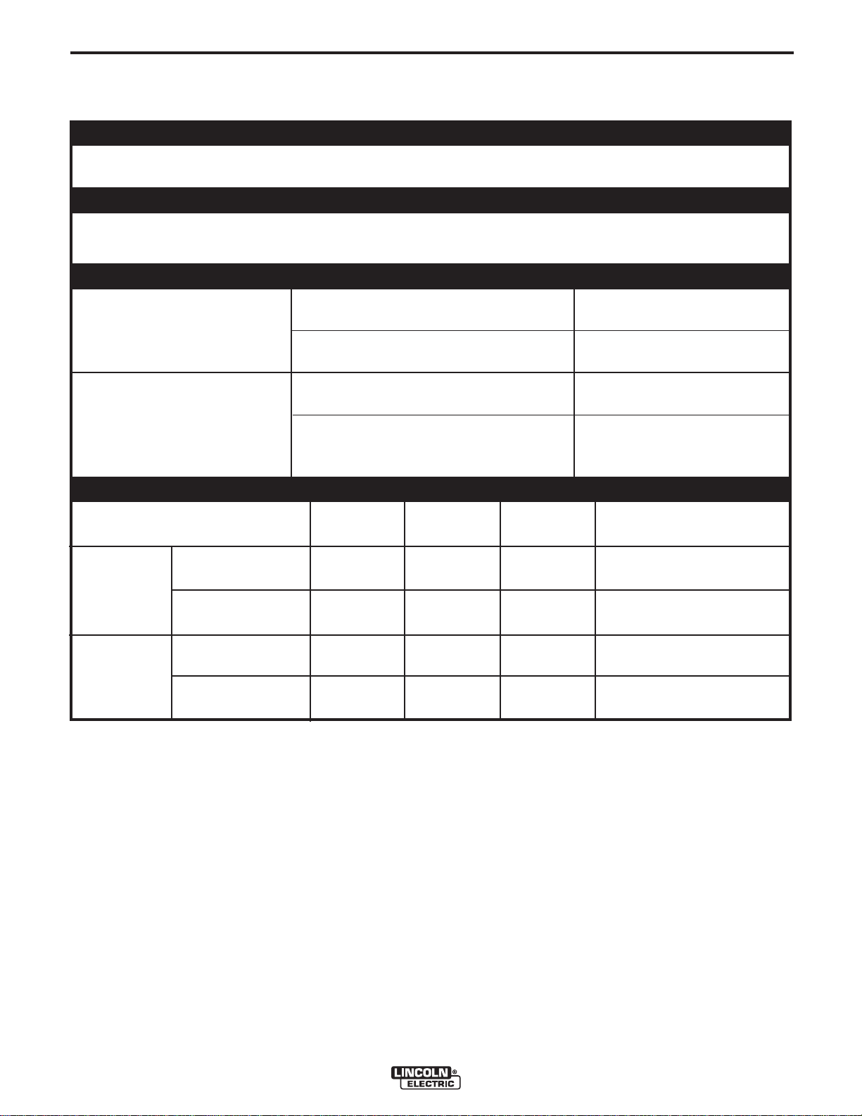
TECHNICAL SPECIFICATIONS – LN-7 and LN-7 GMA
INPUT VOLTAGE
Supplied by power source: 115 VAC, 50/60 Hz, 2.5 Amps
WIRE FEED SPEED
LN-7 GMA 75 to 700 in. per minute (1.90 to 17.8 m/min)
LN-7 50 to 500 in. per minute (1.27 to 12.7 m/min)
WIRE DIAMETERS
A-1
TWO
ROLL
FEEDER
FOUR
ROLL
FEEDER
LN-7 GMA
LN-7
WITHOUT
WIRE STAND
WITH WIRE
STAND (K377)
WITHOUT
WIRE STAND
WITH WIRE
STAND (K377)
0.023 in. through 1/16 in.
(0.6 through 1.6 mm)
0.045 in. through 5/64 in.
(1.2 through 2.0 mm)
0.023 in. through 3/32 in.
(0.6 through 2.4 mm)
0.045 in. through 7/64 in.
(1.2 through 2.8 mm)
PHYSICAL DIMENSIONS
LENGTH
9.62 in.
(244 mm)
20.68 in.
(525 mm)
9.70 in.
(246 mm)
20.76 in.
(527 mm)
WIDTH
9.76 in.
(247 mm)
9.76 in.
(247 mm)
11.60 in.
(295 mm)
11.60 in.
(295 mm)
HEIGHT
10.89 in.
(277 mm)
17.00 in.
(432 mm)
11.11 in.
(282 mm)
17.00 in.
(432 mm)
solid electrode
cored electrode
solid electrode
cored electrode
TOTAL WEIGHT
LESS ELECTRODE
24 lbs
(10.9 kg)
36 lbs
(16.3 kg)
30.5 lbs
(13.8 kg)
42.5 lbs
(19.3 kg)
DUTY CYCLE: The amount of welding performed in a 10 minute period, expressed as a percentage.
LN-7 & LN-7 GMA
Page 9

A-2
INSTALLATION
MOUNTING LOCATION
The LN-7 and LN-7 GMA wire feeder can be mounted
directly on top of the power source providing that it is
secure and level. It can also be mounted to an
undercarriage when portability is required.
MACHINE GROUNDING
The LN-7 and LN-7 GMA wire feeders are ground to
the power source through the input cable. The power
source grounding terminal must be properly connected
to electrical ground per the power source operating
manual.
INPUT CABLE CONNECTIONS
Various input cable assemblies are available for the
LN-7 GMA wire feeder. Refer to the Accessories
section for complete descriptions
A-2
WARNING
Turn input power off before connecting the LN-7
GMA wire feeder.
------------------------------------------------------------------------
For connecting an LN-7 GMA to a specific Lincoln
power source follow steps 1 through 6, and refer to the
connection diagrams in Figure A.3 through A.17 for the
specific power source. Table A.1 lists each figure
number with its corresponding power source.
TABLE A.1 - LN-7 GMA CONNECTION DIAGRAMS
Figure # Power Source
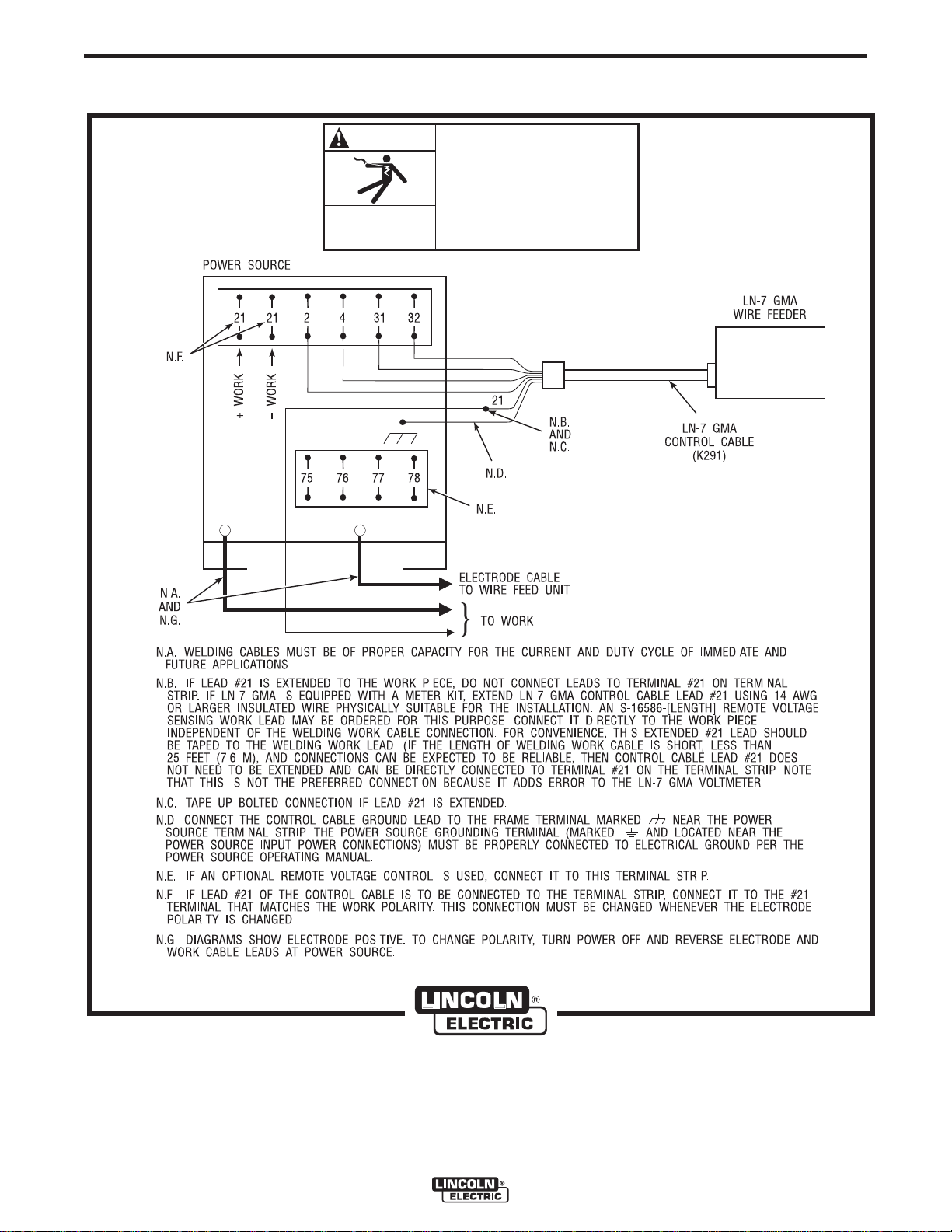
A.3 LN-7 GMA To DC-400, DC-250 and CV/CVI Power Sources With Terminal Strip - Connection
Diagram
A.4 LN-7 GMA To Pulsed Power 500 - Connection Diagram
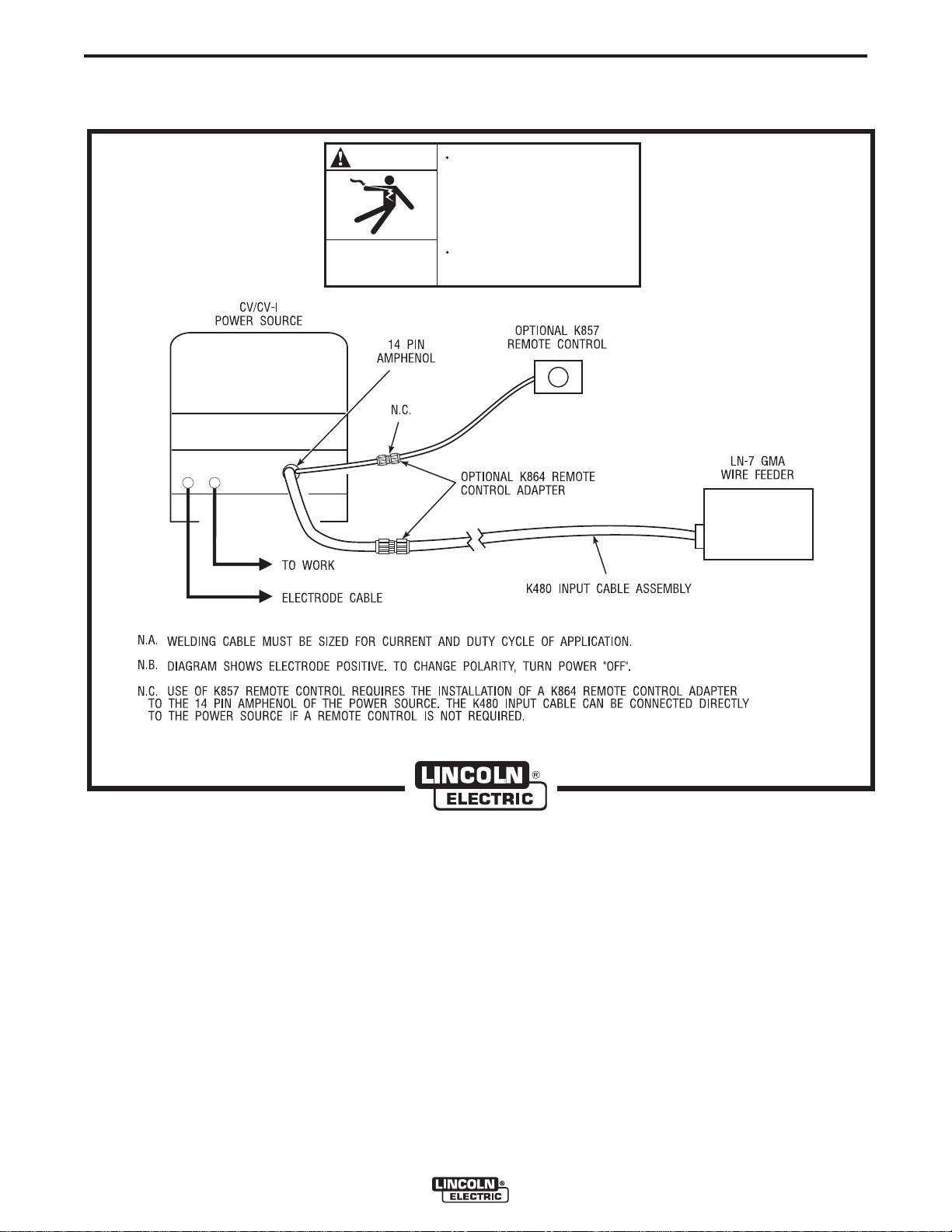
A.5 LN-7 GMA To CV/CVI Power Sources With 14 Pin Amphenol Connector - Connection Diagram
A.6 LN-7 GMA To CV/CVI Power Sources With Twist-Mate Connector and 14 Pin Amphenol/Remote
Control - Connection Diagram
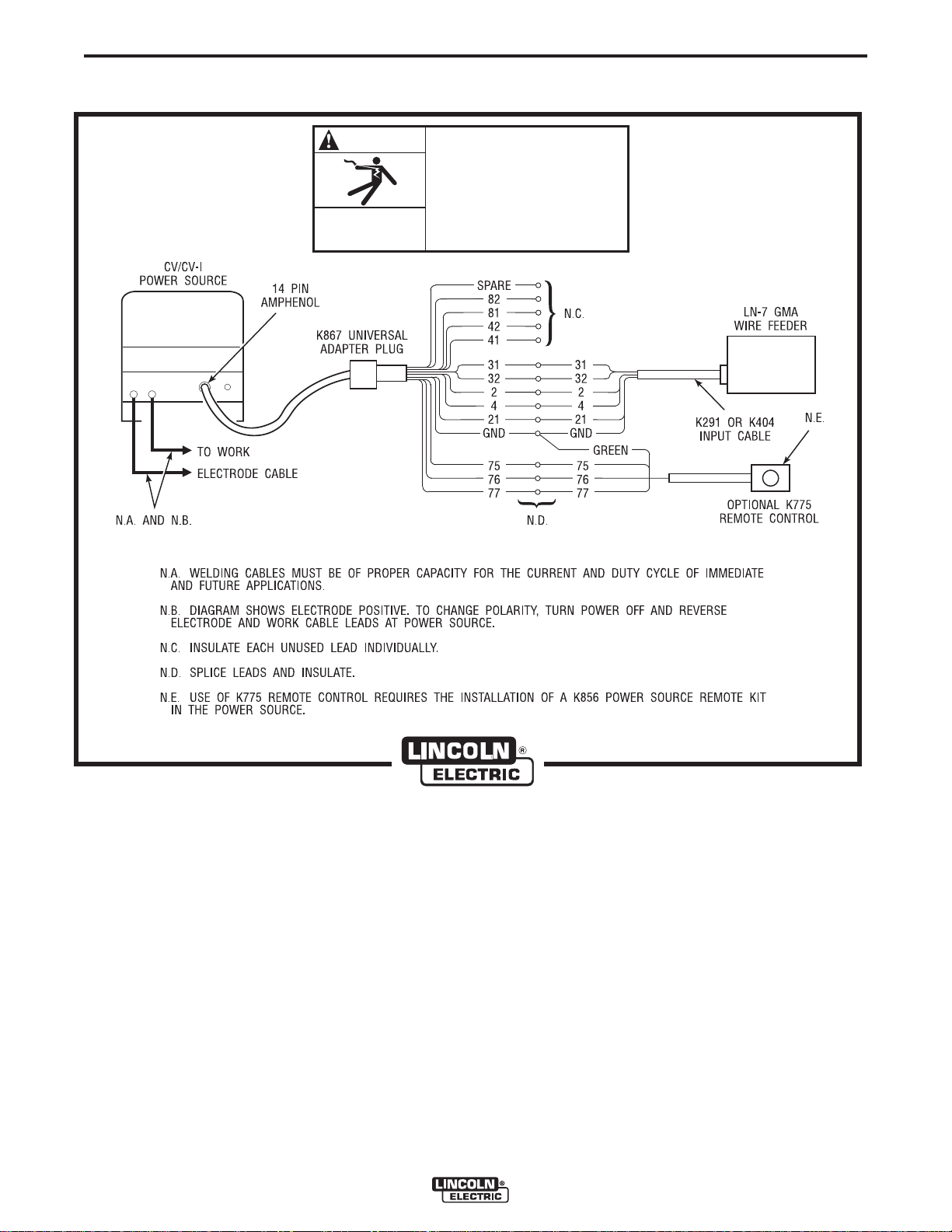
A.7 LN-7 GMA To CV/CVI Power Source (K867/K775) - Connection Diagram
A.8 LN-7 GMA To R3S-250 or R3S-325 - Connection Diagram
A.9 LN-7 GMA To SAM Motor Generator or Engine Welder - Connection Diagram
A.10 LN-7 GMA To DC-600 - Connection Diagram
A.11 LN-7 GMA To R3S-400, 600, or 800 - Connection Diagram
A.12 LN-7 GMA To Most Lincoln Motor Generators - Connection Diagram
A.13 LN-7 GMA To WP250 or G9 PRO - Connection Diagram
A.14 LN-7 GMA To Ranger 9 - Connection Diagram
A.15 LN-7 GMA To Ranger 10-LX - Connection Diagram
A.16 LN-7 GMA To Power Sources With No Output Contactor - Connection Diagram
A.17 LN-7 GMA To Power Sources With Contactor and No Terminal Strip - Connection Diagram
A.18 LN-7 GMA To FLEXTEC 650 - Connection Diagram
LN-7 & LN-7 GMA
Page 10
A-3
INSTALLATION
A-3
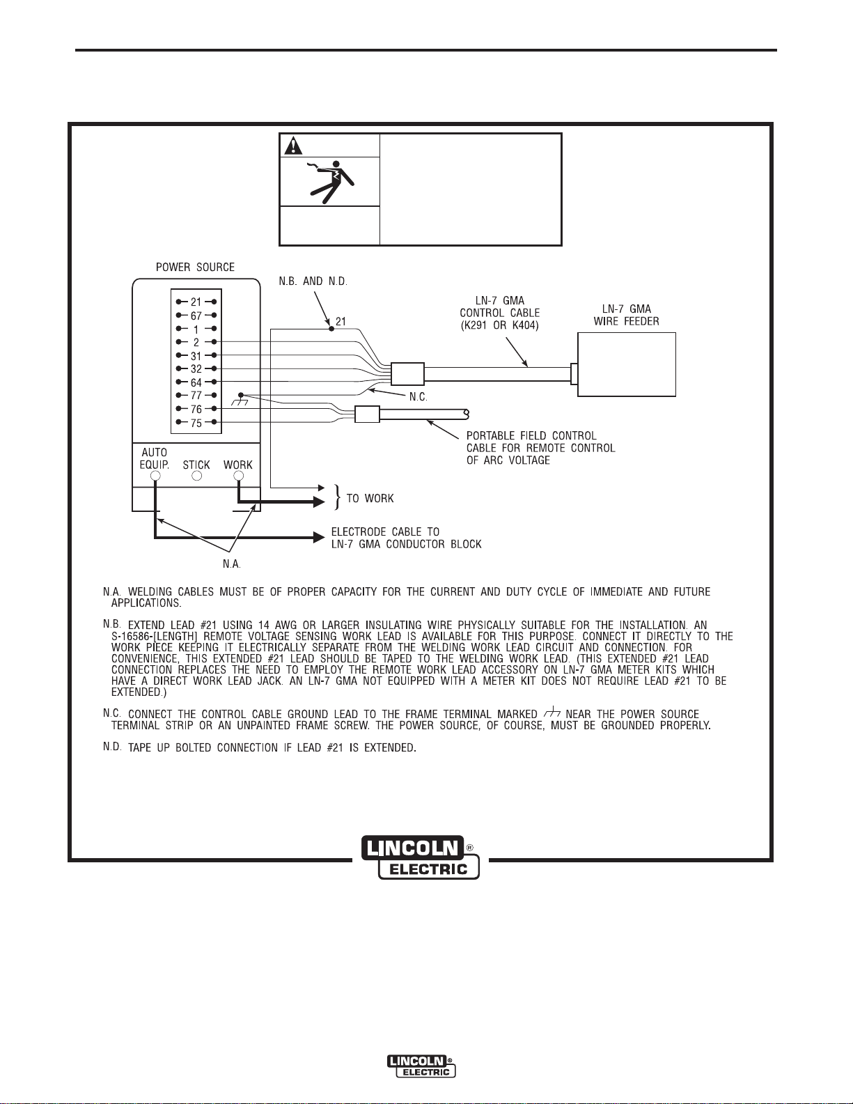
1. For K291 and K404 cables, connect the end of the
control cable with the lugged leads to the power
source. If lead #21 is extended to work, do not
connect leads to terminal #21 on terminal strip.
For K584, K594 or K480 cables connect the 14
pin amphenol connector to the power source.
Include any jumpers called for on the connection
diagram. Do not add any other jumpers or
connections.
WARNING
Never operate a Lincoln power source that has a
jumper from #2 to #4 on the terminal strip, or a
power source without a contactor, with this wire
feeder. To do so would defeat the purpose of the
grounding lead protector circuit and could result in
the overheating of the electrical ground circuit to
the wire feeder.
------------------------------------------------------------------------
2. For constant voltage power sources with an
output contactor but no terminal strip or 14-pin
control receptacle, see Figure A.17. For constant
voltage power sources without an internal output
contactor, and requiring a K240 Contactor Kit,
see Figure A.16.
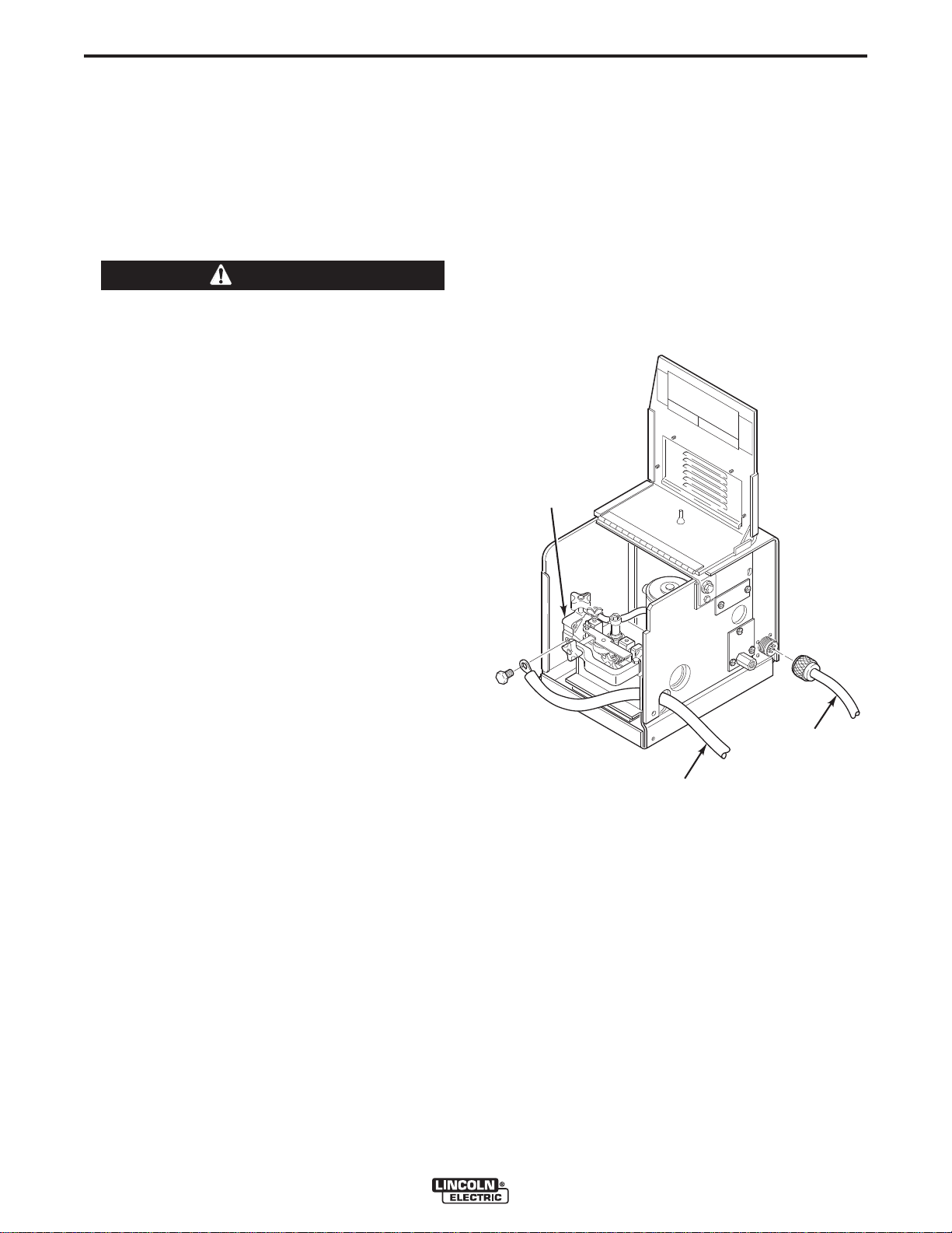
4. Referring to Figure A.1, route the end of the
electrode cable through the large hole in the back
panel of the LN-7 case. Connect the electrode
cable to the brass conductor block on the front of
the gearbox using the 1/2-13 x .75 bolt provided.
Be sure the cable is placed to allow easy
access and clearance for the idle roll arm
pressure adjustment and to allow the drive
roll section cover to close.
FIGURE A.1 – INPUT CONTROL CABLE AND
ELECTRODE CABLE CONNECTIONS.
CONDUCTOR
BLOCK
If input cables longer than the standard length
3.
must be used, K292 extension cables (50 ft/15.2
m) can be installed. These have polarized plugs
on each end of the control cable and include a 4/0
(107 mm
between the standard input cable and the wire
feeder. Total input cable length should not exceed
400 ft (122 m). When using longer lengths of
extension cables, it may be necessary to add
parallel electrode cables to minimize the voltage
drop in the cable.
2
) electrode cable. Install the extensions
CONTROL
CABLE
ELECTRODE
LN-7 & LN-7 GMA
Page 11

A-4
INSTALLATION
A-4
5. Connect the input control cable polarized
Amphenol plug into the mating 6-pin receptacle
on the rear of the control section.
6. Referring to Figure A.2, install the input cable
under the wire reel mounting stand strain relief
FIGURE A.2 – STRAIN RELIEF CLAMP.
clamp. Remove the screws holding the clamp to
the base of the wire reel mounting assembly, put
the input cable assembly under the clamp and
reinstall the screws.
CONTROL
CABLE
STRAIN
RELIEF
CLAMP
ELECTRODE
CABLE
LN-7 & LN-7 GMA
Page 12
A-5
INSTALLATION
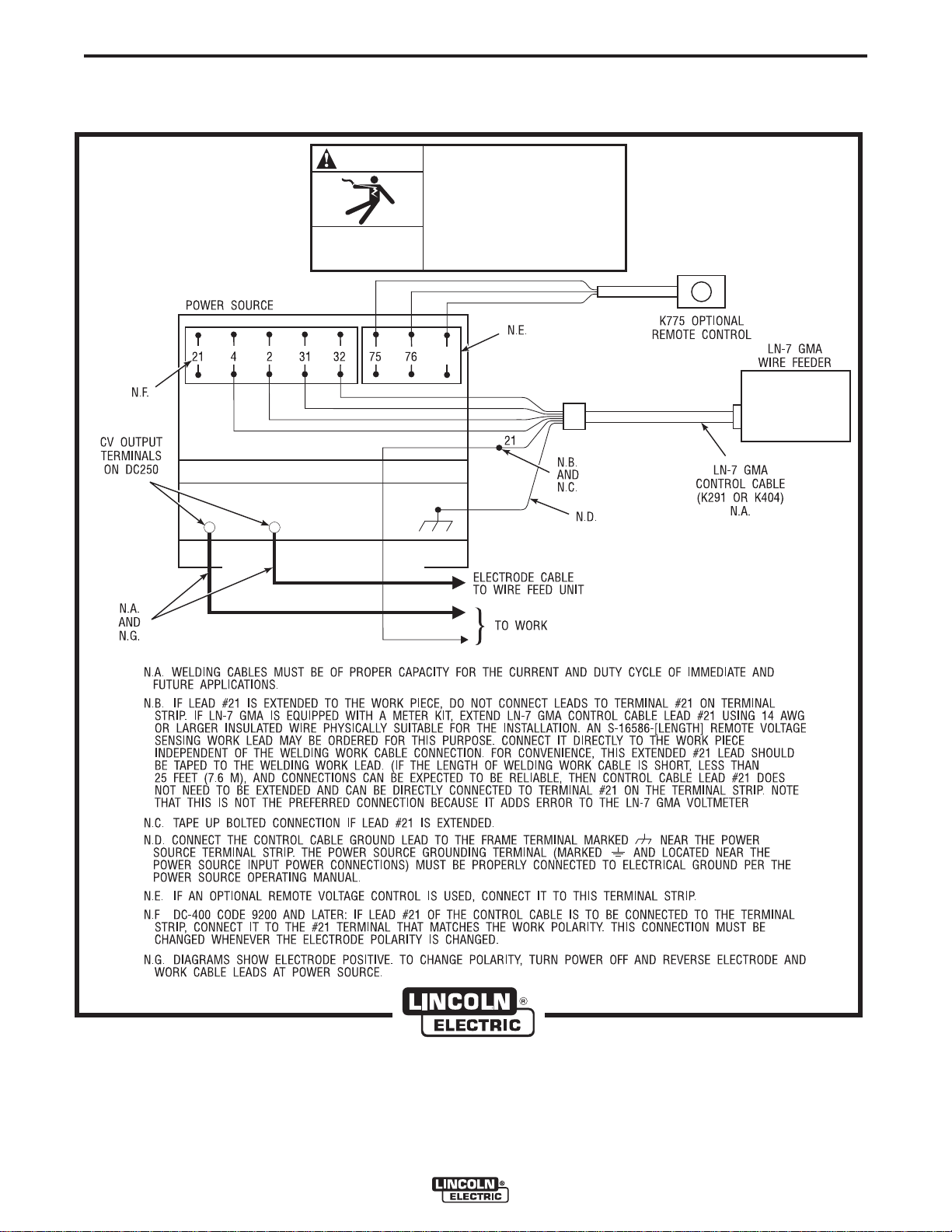
FIGURE A.3 – LN-7 & LN-7 GMA TO DC-400, DC-250 AND CV/CVI POWER SOURCES WITH
TERMINAL STRIP - CONNECTION DIAGRAM.
A-5
WARNING
ELECTRIC
SHOCK
CAN KILL
–
+
TURN INPUT POWER OFF
BEFORE CONNECTING THE
LN-7 GMA WIRE FEEDER.
77
LN-7 & LN-7 GMA
CLEVELAND, OHIO U.S.A
Page 13
A-6
INSTALLATION
FIGURE A.4 – LN-7 & LN-7 GMA TO PULSED POWER 500 - CONNECTION DIAGRAM.
A-6
WARNING
ELECTRIC
SHOCK
CAN KILL
–
+
TURN INPUT POWER OFF
BEFORE CONNECTING THE
LN-7 GMA WIRE FEEDER.
LN-7 & LN-7 GMA
CLEVELAND, OHIO U.S.A
Page 14

A-7
INSTALLATION
FIGURE A.5 – LN-7 & LN-7 GMA TO CV/CVI POWER SOURCES WITH 14 PIN AMPHENOL
CONNECTOR - CONNECTION DIAGRAM.
A-7
WARNING
ELECTRIC
SHOCK
CAN KILL
+
–
TURN INPUT POWER OFF
BEFORE CONNECTING THE
LN-7 GMA WIRE FEEDER.
LN-7 & LN-7 GMA
CLEVELAND, OHIO U.S.A
Page 15
A-8
INSTALLATION
FIGURE A.6 – LN-7 & LN-7 GMA TO CV/CVI POWER SOURCES WITH TWIST-MATE CONNECTOR
AND 14 PIN AMPHENOL/REMOTE CONTROL - CONNECTION DIAGRAM.
A-8
WARNING
ELECTRIC
SHOCK
CAN KILL
+
–
TURN OFF INPUT POWER
TO THE WELDING POWER
SOURCE USING THE
DISCONNECT SWITCH AT
THE FUSE BOX BEFORE
CONNECTING THE WIRE
FEEDER.
ONLY QUALIFIED PERSONS
SHOULD INSTALL, USE, OR
SERVICE THIS MACHINE.
LN-7 & LN-7 GMA
CLEVELAND, OHIO U.S.A
Page 16
A-9
INSTALLATION
FIGURE A.7 – LN-7 & LN-7 GMA TO CV/CVI POWER SOURCE (K867/K775) - CONNECTION DIAGRAM.
A-9
WARNING
ELECTRIC
SHOCK
CAN KILL
–+
TURN INPUT POWER OFF
BEFORE CONNECTING THE
LN-7 GMA WIRE FEEDER.
LN-7 & LN-7 GMA
CLEVELAND, OHIO U.S.A
Page 17

A-10
INSTALLATION
FIGURE A.8 – LN-7 & LN-7 GMA TO R3S-250 OR R3S-325 - CONNECTION DIAGRAM.
A-10
–+
WARNING
ELECTRIC
SHOCK
CAN KILL
TURN INPUT POWER OFF
BEFORE CONNECTING THE
LN-7 GMA WIRE FEEDER.
LN-7 & LN-7 GMA
CLEVELAND, OHIO U.S.A
Page 18
A-11
INSTALLATION
FIGURE A.9 – LN-7 & LN-7 GMA TO SAM MOTOR GENERATOR OR ENGINE WELDER - CONNECTION
DIAGRAM.
A-11
WARNING
ELECTRIC
SHOCK
CAN KILL
TURN INPUT POWER OFF
BEFORE CONNECTING THE
LN-7 GMA WIRE FEEDER.
LN-7 & LN-7 GMA
CLEVELAND, OHIO U.S.A
Page 19

A-12
INSTALLATION
FIGURE A.10 – LN-7 & LN-7 GMA TO DC-600 - CONNECTION DIAGRAM.
A-12
WARNING
ELECTRIC
SHOCK
CAN KILL
–
+
TURN INPUT POWER OFF
BEFORE CONNECTING THE
LN-7 GMA WIRE FEEDER.
LN-7 & LN-7 GMA
CLEVELAND, OHIO U.S.A
Page 20

A-13
INSTALLATION
FIGURE A.11 – LN-7 & LN-7 GMA TO R3S-400, 600, OR 800 - CONNECTION DIAGRAM.
A-13
WARNING
ELECTRIC
SHOCK
CAN KILL
TURN INPUT POWER OFF
BEFORE CONNECTING THE
LN-7 GMA WIRE FEEDER.
LN-7 & LN-7 GMA
CLEVELAND, OHIO U.S.A
Page 21

A-14
INSTALLATION
A-14
FIGURE A.12 – LN-7 & LN-7 GMA TO MOST LINCOLN MOTOR GENERATORS - CONNECTION DIAGRAM.
32
WARNING
ELECTRIC
SHOCK
CAN KILL
TURN INPUT POWER OFF
BEFORE CONNECTING THE
LN-7 GMA WIRE FEEDER.
LN-7 & LN-7 GMA
CLEVELAND, OHIO U.S.A
Page 22

A-15
INSTALLATION
FIGURE A.13 – LN-7 & LN-7 GMA TO WP250 OR G9 PRO - CONNECTION DIAGRAM.
A-15
WARNING
ELECTRIC
SHOCK
CAN KILL
TURN INPUT POWER OFF
BEFORE CONNECTING THE
LN-7 GMA WIRE FEEDER.
CAUTION
AUXILIARY
VOLTAGE MUST
NOT EXCEED
140 VOLTS.
LN-7 GMA TO WP250 G9
PRO: ANY INCREASE OF THE
HIGH IDLE ENGINE RPM BY
CHANGING THE GOVERNOR
SETTING OR OVERRIDING
THE THROTTLE LINKAGE
WILL CAUSE AN INCREASE
IN THE AC AUXILIARY
VOLTAGE. IF THIS VOLTAGE
GOES ABOVE 140 VOLTS,
THE LN-7 GMA CONTROL
CIRCUIT WILL BE DAMAGED.
THE ENGINE GOVERNOR
SETTING IS PRE-SET AT THE
FACTORY - DO NOT ADJUST
ABOVE RPM SPECIFICATIONS
LISTED IN ENGINE WELDER
OPERATING MANUAL.
LN-7 & LN-7 GMA
CLEVELAND, OHIO U.S.A
Page 23

A-16
INSTALLATION
FIGURE A.14 – LN-7 & LN-7 GMA TO RANGER 9 – CONNECTION DIAGRAM.
A-16
WARNING
ELECTRIC
SHOCK
CAN KILL
DO NOT OPERATE WITH
PANELS OPEN.
DISCONNECT NEGATIVE (-)
BATTERY LEAD BEFORE
SERVICING.
DO NOT TOUCH
ELECTRICALLY LIVE PARTS.
WARNING
MOVING
PARTS
CAN INJURE
KEEP GUARDS IN PLACE.
KEEP AWAY FROM MOVING
PARTS.
ONLY QUALIFIED PERSONS
SHOULD INSTALL, USE, OR
SERVICE THIS MACHINE.
LN-7 & LN-7 GMA
CLEVELAND, OHIO U.S.A
Page 24

A-17
INSTALLATION
FIGURE A.15 – LN-7 & LN-7 GMA TO RANGER 10-LX – CONNECTION DIAGRAM.
A-17
WARNING
ELECTRIC
SHOCK
CAN KILL
DO NOT OPERATE WITH
PANELS OPEN.
DISCONNECT NEGATIVE (-)
BATTERY LEAD BEFORE
SERVICING.
DO NOT TOUCH
ELECTRICALLY LIVE PARTS.
WARNING
MOVING
PARTS
CAN INJURE
KEEP GUARDS IN PLACE.
KEEP AWAY FROM MOVING
PARTS.
ONLY QUALIFIED PERSONS
SHOULD INSTALL, USE, OR
SERVICE THIS MACHINE.
LN-7 & LN-7 GMA
CLEVELAND, OHIO U.S.A
Page 25

A-18
INSTALLATION
FIGURE A.16 – LN-7 & LN-7 GMA TO POWER SOURCES WITH NO OUTPUT
CONTACTOR - CONNECTION DIAGRAM.
A-18
WARNING
ELECTRIC
SHOCK
CAN KILL
TURN INPUT POWER OFF
BEFORE CONNECTING THE
LN-7 GMA WIRE FEEDER.
LN-7 & LN-7 GMA
CLEVELAND, OHIO U.S.A
Page 26

A-19
INSTALLATION
FIGURE A.17 – LN-7 & LN-7 GMA TO POWER SOURCES WITH CONTACTOR AND NO TERMINAL
STRIP - CONNECTION DIAGRAM.
A-19
WARNING
ELECTRIC
SHOCK
CAN KILL
TURN INPUT POWER OFF
BEFORE CONNECTING THE
LN-7 GMA WIRE FEEDER.
LN-7 & LN-7 GMA
CLEVELAND, OHIO U.S.A
Page 27

A-20
FLEXTEC™-650
INSTALLATION
FIGURE A.18 – LN-7 & LN-7 GMA TO FLEXTEC 650 - CONNECTION DIAGRAM.
WIRE FEEDER
14-PIN CONTROL CABLE K1818-XX
ELECTRODE
WORK
LN-7
LN-7GMA
A-20
WELD MODE
WELD TERMINALS
REMOTE/LOCAL
VOLTMETER POLARITY
CONTROL SETTING
CV, CV-INNERSHIELD
OFF
LOCAL
PROCESS DEPENDENT
LN-7 & LN-7 GMA
Page 28

A-21
INSTALLATION
A-21
WORK CABLE
Connect a work lead of sufficient size and length
(Table A.2) between the proper output stud on the
power source and the work. Be sure the connection to
the work makes tight metal-to-metal electrical contact.
Poor work lead connections can result in the grounding
lead protector being activated.
TABLE A.2 – WORK LEAD SPECIFICATIONS
Copper Work Cable Size, AWG
Current 60% Up To 50 Ft 50 Ft-100 Ft
2
Duty Cycle (15.2 m
300 Amps 0 (53 mm
400 Amps 00 (67 mm2) 000 (85 mm2)
500 Amps 00 (67 mm2) 000 (85 mm2)
600 Amps 000 (85 mm2) 0000 (107 mm2)
) (15.2-30.4 m2)
2
) 00 (67 mm2)
GUN AND CABLE ASSEMBLIES
the control cable amphenol plug into the mating 5cavity receptacle on the front of the control section
below the nameplate.
If using the K489-1 Fast-Mate Adapter, install per the
S19389 instructions included with the kit.
FIGURE A.19 – GUN CABLE CONNECTIONS.
The LN-7 and LN-7 GMA can be used with several
guns. In most cases, Lincoln guns and cables are
shipped assembled, ready to weld. Use the gun and
cable assembly for the electrode type (solid,
Outershield , or Innershield) and electrode size to be
used. Refer to the Accessories Section for different
gun types.
GUN CABLE CONNECTIONS
Lay the cable out straight. Insert the connector on the
welding conductor cable through the large hole in the
front panel of the LN-7 and into the brass conductor
block on the front of the gearbox. Refer to Figure A.19.
Make sure it is all the way in and tighten the hand
wheel. Keep this connection clean and bright. Connect
AMPHENOL
CONNECTOR
CONDUCTOR
BLOCK
GUN CABLE
ASSEMBLY
LN-7 & LN-7 GMA
Page 29

A-22
ONT
BAC
INSTALLATION
A-22
WATER CONNECTIONS
(FOR WATER COOLED GUNS)
The LN-7 or LN-7 GMA must have a K527 Water
Solenoid Kit installed (see the Accessories Section).
The K440-1 LN-7 GMA model already has a water
solenoid installed. Refer to Figure A.20 and perform
the following steps:
NOTE: If not using a Lincoln water cooler , and if your
water cooling device is not designed for use with a
waterline solenoid valve, you may remove the solenoid
and screw the male fitting (after applying sealant)
directly into the brass manifold block.
FIGURE A.20 – WATER CONNECTIONS.
1. Using male 5/8-18 UNF left-hand thread fittings,
connect appropriate water hoses to the coolant
inlet and outlet on the back of the LN-7. Connect
the other ends of these hoses to the appropriate
ports on your water cooling units.
2. In the event the water line fittings on your water
cooled gun are incompatible with the female quick
connects on the front of the LN-7, male quick
connects are provided for installation on 3/16 in.
I.D. hose (customer to provide appropriate
clamps). The feeder connectors self seal when
disconnected.
FRFRONT
K
LN-7 & LN-7 GMA
Page 30

A-23
INERT
GAS
FITTING
GAS
HOSE
GAS
SUPPLY
HOSE
INSTALLATION
A-23
SHIELDING GAS HOOKUP (LN-7 GMA
or LN-7 with Optional K494 Gas Solenoid
Installed)
WARNING
Gas under pressure is explosive. Always keep gas
cylinders in an upright position and to the
undercarriage or a stationary support. See
American National Standard Z-49.1, “Safety In
Welding And Cutting”, published by the American
Welding Society.
------------------------------------------------------------------------
Customer must provide a cylinder of shielding gas, a
pressure regulator, a flow control valve, and a hose
FIGURE A.21 – SHIELDING GAS HOOKUP.
from the flow valve to the gas inlet fitting of the LN-7
GMA or the K494 Gas Solenoid Valve Kit installed on
the LN-7. Install per Figure A.21 and the following:
1. Connect the supply hose from the gas cylinder
flow valve outlet to the 5/8-18 female inert gas
fitting on the back panel of the LN-7.
2. Install the barbed fitting and union nut to the
5/8-18 female inert gas fitting on the front of the
LN-7. Connect 3/16 in. (4.8 mm) I.D. gas hose
from the gun to the barbed fitting.
When the gun is to be removed, this fitting can be
easily detached by loosening the union nut.
INER
FITTING
GAS
HOSE
GAS
GAS
SUPPL
HOSE
LN-7 & LN-7 GMA
Page 31

B-1
OPERATION
B-1
Read and understand this entire section before
operating your machine.
SAFETY INSTRUCTIONS
WARNING
ELECTRIC SHOCK can kill.
• Do not touch electrically live parts such
as output terminals or internal wiring.
• Insulate yourself from the work and
ground.
• Always wear dry insulating gloves.
____________________________________
FUMES AND GASES
can be dangerous.
• Keep your head out of fumes.
GENERAL DESCRIPTION
The K440 LN-7 GMA semiautomatic constant speed
wire feeder is specifically equipped for gas metal arc
welding using flux-cored Outershield electrodes and
solid wire. The LN-7 GMA is also suitable for selfshielded flux-cored Innershield electrodes, submerged
arc welding (if constant voltage is satisfactory), and
other open arc welding. It has been factory assembled
with the following features:
• Wire feed dial [75 to 700 in./min (1.9 to 17.8
m/min)].
• Factory installed gas solenoid valve and gas
fittings.
• Wire drive uses a permanent magnet motor and
includes tool-less “quick- release” idle roll pressure
arm, outgoing guide tube and gun cable fastening.
• Optional factory installed water solenoid and fittings
for use with water cooled welding guns.
• Use ventilation or exhaust to
remove fumes from breathing
zone.
____________________________________
WELDING, CUTTING and
GOUGING SPARKS
can cause fire or explosion
• Keep flammable material away.
• Do not weld, cut or gouge on
containers that have held com-
bustibles.
____________________________________
ARC RAYS
can burn.
• Wear eye, ear and body
protection.
The K567-1 LN-7 GMA 4-Roll is designed to provide
the additional feeding force required when using gun
cables over 15 ft (4.6 m) long or when the wire is pulled
long distances (such as when bulk packages are
used). Because the four-roll feeder has twice the
contact surface, it can also help when feeding softer
wires by delivering the same or more feeding force as
the two-roll with less overall wire deformation. Wire
size range, speed and features are the same as other
LN-7 GMA models.
The K521 LN-7 semiautomatic constant speed wire
feeder is recommended for self-shielded flux-cored
Innershield® electrodes, submerged arc welding, and
other open arc welding. It has the following features:
• Wire feed dial [50 to 500 in./min (1.27 to 12.7
m/min)].
• Wire drive uses a permanent magnet motor and
includes tool-less “quick- release” idle roll pressure
arm, outgoing guide tube and gun cable fastening.
• Optional factory installed water solenoid and fittings
for use with water cooled welding guns.
____________________________________
Only qualified personnel should operate this equipment. Observe all safety information throughout this
manual.
LN-7 & LN-7 GMA
Page 32

B-2
OPERATION
B-2
RECOMMENDED PROCESSES AND
EQUIPMENT
The LN-7 GMA is recommended for use in MIG and
Innershield welding applications, the LN-7 is
recommended for Innershield welding applications.
Both are recommended for use with constant voltage
power sources such as the Idealarc DC-250, 400, or
600, or CV types. The LN-7 GMA is capable of feeding
FIGURE B.1 – WIRE FEEDER CONTROLS.
PREFLOW
CONTROL
(OPTIONAL)
PURGE-COLD
INCH SWITCH
(OPTIONAL)
POSTFLOW
CONTROL
(OPTIONAL)
wires ranging from 0.023 in. through 1/16 in. (0.6
through 1.6 mm) solid, 0.045 in. through 5/64 in. (1.2
through 2.0 mm) Innershield, and 0.062 in. through
5/64 in. (1.6 through 2.0 mm) Outershield electrodes.
The LN-7 is capable of feeding wires ranging from
0.023 in. through 3/32 in. (0.6 through 2.4 mm) solid
and 0.045 in. through 7/64 in. (1.2 through 2.8 mm)
cored.
BURNBACK
CONTROL
(OPTIONAL)
WIRE FEED
SPEED CONTROL
CONTROLS AND SETTINGS
Operator controls are illustrated in Figure B.1. Refer to
the figure and the following explanations of the
controls.
WIRE FEED SPEED CONTROL. This control sets the
feed speed of the wire feeder. Turn the knob to the left
for slower speeds and to the right for higher speeds.
The control is calibrated. The nameplate shows the
wire speed for the given setting of the control.
BURNBACK CONTROL (OPTIONAL). This control,
located on the optional K419 Burnback Timer and
K418 GMA Timer Kits, provides a precise time delay
that allows the wire to be burned off at the end of the
weld. This is useful for those applications where higher
speed, fine wire feeding is used and there is a
tendency for the electrode to overrun at the end of the
ELECTRODE
POLARITY SWITCH
(OPTIONAL)
weld and cause “sticking” in the crater. The delay is
adjustable for optimum burnback depending on wire
size, process, procedure, etc.
PREFLOW CONTROL (OPTIONAL). This control,
located on the optional K418 GMA Timer Kit, provides
flow of shielding gas to the work before the arc is
established. The gas solenoid valve is energized
immediately when the gun trigger is closed, but the
time delay before the wire feeder is energized is
adjustable from 0 to 1.5 seconds. Turn the knob to the
left for shorter delays and to the right for longer delays.
POSTFLOW CONTROL (OPTIONAL). This control,
located on the optional K418 GMA Timer Kit, provides
flow of shielding gas to the work after welding has
stopped. Delay for the gas solenoid valve shutoff is
adjustable from 0 to 1.5 seconds. Turn the knob to the
left for shorter delays and to the right for longer delays.
LN-7 & LN-7 GMA
Page 33

B-3
PURGE - COLD INCH SWITCH (OPTIONAL). This
control, located on the optional K418 GMA Timer Kit,
provides control of some wire feeder functions without
energizing the welding power source. The momentary
up position energizes the gas solenoid but not the wire
feeder or welding power source. The momentary down
position energizes the wire feeder but not the gas
solenoid or the welding power source.
ELECTRODE POLARITY SWITCH (OPTIONAL).
This switch, located on the optional K416 Digital and
K417 Analog Meter Kits, controls the polarity of the
meter. Set this switch to the same polarity as the
electrode lead to allow correct operation of the meter.
OPERATION
CIRCUIT PROTECTION
A manual reset circuit breaker protects the AC supply
line and the wire feeder from overloads, usually
caused by excessive wire drag or other wire feed
problems. To reset the circuit breaker, raise the cover
of the wire drive compartment and push the white
button on the side of the control box above the drive
rolls.
The LN-7 and LN-7 GMA also include a Ground Lead
Protector (GLP) circuit and fuse in the 2-4 contactor
circuit.
The frame of the LN-7 wire feed unit is grounded to the
frame of the power source by a lead in the control
cable. The GLP circuit prevents welding current from
damaging this lead if the electrode circuit touches the
wire feeder frame while the gun trigger is pressed.
When the protector circuit is tripped, the wire feed rolls
will not turn and the welding contactor in the power
source will not close when the gun trigger is pressed.
To reset the protector circuit, press the red button
above the drive rolls and to the left of the circuit
breaker. There is no visual indication when the
protector circuit is tripped.
B-3
DO NOT coil excess input cable assembly or use a
coiled assembly as shipped from the factory. Instead,
loop the excess cable length back and forth in three to
six foot straight lengths. Coiling the input cable results
in a transformer action between the electrode
conductor cable and the ground lead in the
multiconductor control cable. This transformer action
can cause a current to flow in the ground lead which
will falsely activate the GLP circuit.
To reset the GLP circuit, press the red button above
the drive rolls and to the left of the circuit breaker.
DRIVE ROLL INSTALLATION
CHANGING DRIVE ROLLS FOR TWOROLL WIRE FEEDERS:
To change drive rolls on a two-roll wire feeder, refer to
Figure B.2 and perform the following steps:
1. Rotate the latch knob on the quick release arm.
2. Remove the hex head screw and clamping collar.
Remove the drive roll from the shaft.
3. The new roll to be installed is stamped for the size to
be fed. An “A” after the size indicates aluminum wire.
Remove the rolls from the kit and wipe them clean.
Wipe the output shaft and locating shoulder clean.
4. Use the drive key, clamping collar, and hex head
screw to install the roll on the output shaft. Certain
size drive rolls consist of two roll halves, and may
contain a spacer. If the drive roll you are installing
contains a spacer, the spacer fits between the two
halves of the drive roll. Tighten the hex head
screw.
5. Back out the guide tube clamping screws.
Remove the old guide tubes, if installed.
AVOIDING GROUND LEAD
PROTECTOR (GLP) ACTIVATION
DO NOT allow the electrode to contact the case of the
wire feeder or the uninsulated part of the wire reel
stand when the gun trigger is activated.
Be sure that all work lead connections to the work
make tight metal-to-metal contact.
DO NOT allow excess input cable or work cable to be
placed closer than three feet from the wire feeder.
LN-7 & LN-7 GMA
6. Insert the outgoing guide tube (the one with the
plastic insert) into the front hole. If the guide tube
has a non-symmetrical chisel end, the larger
radius must face the drive roll. See Figure B.2.
Push the guide tube back as far as it will go and
tighten the clamping screw. Insert the incoming
guide tube as far back as it will go and tighten the
clamping screw. The clamping screws are dog
points. When the guide tubes are properly
installed these dog points will lock into the annular
grooves in each of the guide tubes.
7. Set the idle roll pressure as detailed in the Idle
Page 34

B-4
Roll Pressure Setting procedure detailed later in
this section.
FIGURE B.2 – INSTALLING DRIVE ROLLS ON A TWO-ROLL FEEDER.
OPERATION
B-4
LN-7 & LN-7 GMA
Page 35

B-5
OPERATION
B-5
CHANGING DRIVE ROLLS FOR FOURROLL WIRE FEEDERS:
To change drive rolls on a four-roll wire feeder, refer to
Figure B.3 and perform the following steps:
1. Remove the gun and cable from the conductor
block on the feeder by loosening the hand screw
and pulling the gun straight out of the block.
2. Open both quick release levers by moving the
levers outward and pulling them toward you.
3. Loosen the thumb screws holding the guide tubes
in place. Remove the incoming and outgoing
guide tubes, if installed.
4. Remove the hex head screws and clamping
collars from the output shafts. Remove the drive
rolls and middle guide tube, if installed.
5. The new rolls to be installed are stenciled with the
wire size that will be fed. An “A” after the number
indicates aluminum wire. Remove the rolls from
the kit and wipe them clean. Wipe the output
shafts and locating shoulders clean.
6. Install one roll onto either output shaft using the
drive key, clamping collar, and hex head screw.
Certain size drive rolls consist of two roll halves,
and may contain a spacer. If the drive roll you are
installing contains a spacer, the spacer fits
between the two halves of the drive roll. Tighten
the hex head screw.
7. Install the middle guide tube, but do not tighten at
this time. When installing a 0.035” middle guide
tube the larger radius should be aligned towards
the drive roll. Slide the guide tube up against the
drive roll.
8. Install the second drive roll on the remaining shaft
the same way as the first. Center the middle guide
tube between the rolls and tighten the
thumbscrews holding it in place.
9. Close and latch both quick release levers.
10. Slide the incoming guide tube into the rear hole of
the gearbox until it almost touches the drive roll
and guide tube. Tighten the thumbscrew to hold it
in place.
11. Install the outgoing guide tube into the front hole
of the gearbox (through the conductor block) and
tighten the thumb screw. The 0.035 in. outgoing
guide tube should have the larger radius oriented
toward the drive roll. For proper installation of the
outgoing guide tube insert, refer to Figure B.3.
12. Be certain that the guide tubes do not touch the
drive rolls or idle rolls. If they do touch, readjust
them and tighten in place.
LN-7 & LN-7 GMA
Page 36

B-6
FIGURE B.3 – INSTALLING DRIVE ROLLS ON A FOUR-ROLL FEEDER.
DRIVE
ROLL
HALVES
OPERATION
CLAMPING
COLLAR
SPACER (IF
REQUIRED)
B-6
KEY
GUIDE TUBE DETAIL
OUTGOING
GUIDE TUBE
INSERT
OUTPUT
SHAFT
OUTGOING
GUIDE TUBE
IDLE
ROLL
LARGE
RADIUS
DRIVE
ROLL
MIDDLE
GUIDE
TUBE
SMALL
RADIUS
LN-7 & LN-7 GMA
Page 37

B-7
OPERATION
B-7
IDLE ROLL PRESSURE SETTING
The idle roll pressure is set at the factory. Two-roll
feeders are set with the pressure adjustment knob
backed out two turns from full pressure, and four-roll
feeders are set backed out three turns. This is an
approximate setting. For small wire sizes and
aluminum wire the optimum idle roll pressure varies
with type of wire, surface condition, lubrication, and
hardness. The optimum idle roll setting can be
determined as follows:
Two-roll wire feeders:
1. Press the end of the gun against a solid object
that is electrically isolated from the welder output
and press the trigger for several seconds.
2. If the wire “birdnests”, jams, or breaks at the drive
roll, the idle roll pressure is set too high. Back the
pressure adjustment knob, Figure B.4, out 1/2
turn. Run new wire through the gun and repeat
step 1.
2. After outgoing pressure is set, determine how
many turns away from full pressure the setting is.
3. Set both idle roll tensions to this setting. Engage
both idle rolls before welding. For most
applications, best wire feeding will occur when
both idle roll pressures are set the same.
FIGURE B.4 – IDLE ROLL PRESSURE SETTING.
3. If the only result is drive roll slippage, loosen the
gun cable clamping screw on the conductor block
and pull the gun cable forward about six inches.
There should be a slight waviness in the exposed
wire. If there is no waviness, the pressure is too
low. Increase the pressure setting 1/4 turn. Lock
the gun cable in place and repeat steps 1 and 2.
Four-roll wire feeders:
1. Release the incoming idle roll and perform the
pressure setting procedure for two roll feeders to
set outgoing idle roll pressure.
PRESSURE
ADJUSTMENT
KNOB
LN-7 & LN-7 GMA
Page 38

B-8
OPERATION
B-8
WIRE LOADING
WIRE REEL LOADING – READI-REELS
AND SPOOLS
TO MOUNT A 30 LB READI-REEL PACKAGE
USING THE MOLDED PLASTIC K363-P TYPE
ADAPTER:
1. Make certain that the threaded locking collar is
tight and securely locks the adapter on the
spindle. See Figure B.5.
2. Rotate the spindle and adapter so the retaining
spring is at the 12 oʼclock position.
3. Position the Readi-Reel so that it will rotate in a
clockwise direction when feeding (wire is to be
de-reeled from the bottom of the coil).
4. Set one of the Readi-Reel inside cage wires on
the slot in the retaining spring tab.
5. Lower the Read-Reel to depress the retaining
spring and align the other inside cage wires with
the grooves in the adapter.
6. Slide the cage all the way onto the adapter until
the retaining spring “pops up” fully.
WARNING
Check to be sure the retaining spring has been
fully returned to the locking position and has
SECURELY locked the Readi-Reel cage in place.
Retaining spring must rest on the cage, not the
welding electrode.
------------------------------------------------------------------------
7. To remove the Readi-Reel from the adapter,
depress the retaining spring with thumb while
pulling the Readi-Reel cage from the adapter with
both hands. Do not remove the adapter from the
spindle.
2 IN. O.D. SPINDLE ADAPTER
BRAKE
HOLDING
PIN
FIGURE B.5 – INSTALLING A 30 LB READI-REEL PACKAGE.
RETAINING SPRING
GROOVES
READI-REEL
LN-7 & LN-7 GMA
INSIDE CAGE WIRES THREADED
LOCKING
COLLAR
Page 39

B-9
OPERATION
B-9
TO MOUNT 10 TO 30 LB SPOOL (12” DIAMETER):
(For 8 in. spools a K468 spindle adapter must be
used.)
1. Remove the locking collar and Read-Reel
adapter shipped on the 2 in. diameter spindle
(adapter is not required).
2. Place the spool on the spindle making certain the
brake holding pin enters one of the holes in the
back side of the spool. Be certain the wire comes
off the reel in a clockwise direction when dereeled form the bottom of the coil.
3. Replace and tighten the locking collar.
ELECTRODE FEEDING AND BRAKE
ADJUSTMENT
1. Turn the Readi-Reel or spool until the free end of
the electrode is accessible.
2. While tightly holding the electrode, cut off the bent
end and straighten the first six inches. Cut off the
first inch. (If the electrode is not properly
straightened, it may not feed or may not go into
the outgoing guide tube, causing a “birdnest”.)
3. Insert the free end through the incoming guide
tube.
4. Press the gun trigger and push the electrode into
the drive roll.
WARNING
ELECTRIC SHOCK
can kill.
• Do not touch electrically live parts
such as output terminals or
internal wiring.
• When inching with the gun
trigger, electrode and drive
mechanism are “hot” to work and
ground.
------------------------------------------------------------------------
5. Inch the electrode through the gun.
Adjust the brake tension with the thumbscrew on
6.
the spindle hub until the reel turns freely but with
little or no overrun when wire feeding is stopped.
Do not overtighten.
LN-7 & LN-7 GMA
Page 40

B-10
OPERATION
B-10
WIRE REEL LOADING – 50 AND 60 LB
COILS (K303 OR K376 WIRE REEL STAND)
ADJUSTABLE WIRE REEL BRAKE
The mount for standard 50 and 60 pound electrode
coils includes a two-position brake assembly.
Generally the brake should be at the inner position
(nearest to the wire reel shaft) for wire feed speeds
below 400 in./min (10 m/min). It should be at the outer
position for the faster wire speeds often used when
feeding smaller diameter electrode.
To adjust the brake position, remove the wire reel. Pull
the cotter pin that holds the brake shoe to the arm,
move the shoe and replace the cotter pin. Do not bend
the cotter pin - it is held in place by a friction fit.
TO MOUNT A 50 OR 60 LB COIL:
1. To remove the wire reel from its shaft, grasp the
spring loaded knob and pull out. This straightens
the knob so it seats into the shaft when released.
Remove the reel.
2. Lay the reel flat on the floor. Loosen the spinner
nut and remove the cover plate. See Figure B.6.
CAUTION
Always be sure the free end of the coil is securely held
while the tie wires are being cut and until the wire is
feeding through the drive rolls. Failure to do this will
result in “back lashing” of the coil, which may tangle the
wire. A tangled coil will not feed. It must be untangled
or discarded.
------------------------------------------------------------------------
8. Cut and remove only the tie wire holding the free
end of the coil. Insert the free end into one of the
holes in the cover and secure it by bending it
back. Cut and remove the remaining tie wires.
9.
Replace the reel on the wire feeder. Grasp the
shaft knob, pull it out and swing it across the reel
hub, locking the reel in place.
FIGURE B.6 – LOADING A 50 OR 60 LB COIL.
SPINNER
NUT
COVER
PLATE
3. Place the coil of electrode on the reel so it
unwinds as the reel rotates clockwise. DO NOT
cut the tie wires at this time.
4. Be sure the coil is placed so the spring loaded
arms will not interfere with the later removal of the
coil tie wires.
5. When loading 0.030, 0.035, and 0.045” electrode,
be certain the coil is placed on the reel so the
spring loaded arms are at the center of the slots
in the cardboard coil liner. This provides the
positive compression of the coil sides needed for
trouble-free wire feeding.
6. Put the cover plate on the reel so the four arms of
the cover plate straddle and are in line with the
spring loaded arms of the reel.
7. Tighten the cover as much as possible by hand.
DO NOT hammer on the spinner nut arms.
COIL
REEL
SLOTS
CARDBOARD
COIL
LINER
TIE WIRE
SPRING
LOADED
ARM
LN-7 & LN-7 GMA
Page 41

B-11
OPERATION
B-11
FEEDING ELECTRODE
1. Turn the reel until the free end of the electrode is
accessible.
2. While tightly holding the electrode, cut off the bent
end and straighten the first six inches. Cut off the
first inch. (If the electrode is not properly
straightened, it may not feed or may not go into
the outgoing guide tube causing a “birdnest”.)
3. Insert the free end through the incoming guide
tube.
4. Press the gun trigger and push the electrode into
the drive roll.
WARNING
ELECTRIC SHOCK
can kill.
• Do not touch electrically live parts
such as output terminals or
internal wiring.
• When inching with the gun
trigger, electrode and drive
mechanism are “hot” to work and
ground.
WIRE LOADING – 13-14 LB INNERSHIELD
COILS
The K378 small mounting stand for the 14 lb
Innershield coil does not have an adjustable brake. It
has a fixed drag built into the reel spindle.
To load a 14 lb coil:
1. Remove the snap-on lid from the plastic canister.
2. Remove the center clamping nut and the cover
plate from the wire reel.
3. Unpack the 14 lb coil of wire. Be sure not to bend
the side tangs of the liner. Straighten any tangs
that may have been bent.
4. Remove the start end of the coil from its holding
slot in the coil liner. Cut off the bent end,
straighten the first six inches, and cut off the first
inch. (If the electrode is not properly straightened,
it may not feed or may not enter the outgoing
tube, causing a “birdnest”.)
5. Thread the end through the canister wire feed
liner until about four inches of electrode are
exposed.
6. Place the coil onto the disc support.
7. Replace the front reel cover and center clamping
nut. Keep the reel from turning and tighten the
center clamping nut securely.
5. Inch the electrode through the gun.
8. Thread the exposed end of the electrode into the
wire feeder until it touches the drive rolls. Actuate
the gun trigger and feed the electrode through the
system.
LN-7 & LN-7 GMA
Page 42

B-12
OPERATION
B-12
ACCELERATION SETTING
The LN-7 and LN-7 GMA can be configured for
optimum starting for different procedures by selecting
between two speeds of controlled wire acceleration. As
shipped from the factory, the LN-7 and LN-7 GMA
models are set for fast acceleration. Fast acceleration
is typically the best for most smaller wire procedures.
Slow acceleration may be more desirable for long
stickout applications, or if a larger diameter electrode is
being used.
Acceleration is set on the control PC board. To gain
access to the control PC board, make certain the input
power is off and remove the side cover on the control
side of the LN-7 or LN-7 GMA. To change the
acceleration on earlier control PC boards, reconnect
the jumper to “F” (Fast) or “S” (Slow). Later control PC
boards use a DIP switch (S101). S101 has 8 circuits
(switches); only circuit #1 is used. Set circuit #1 in the
“F” position for fast acceleration or in the “S” position
for slow acceleration. See Figure B.7.
FIGURE B.7 – ACCELERATION SETTING
(LATER CONTROL PC BOARDS).
WIRE SPEED AND VOLTAGE
ADJUSTMENT
Use only constant voltage power type sources. If using
a multiple process power source, be sure it is set for
constant voltage output per instructions in the manual
for the power source.
Set the power source polarity switch or properly
connect the electrodes and work leads for the correct
electrode polarity. If the wire feeder is equipped with an
optional meter kit, set the meter polarity switch to the
proper working polarity.
Set the voltage using the control on the power source
or the optional remote voltage control, if used. Set the
open circuit voltage to approximately 2 volts higher
than the desired procedure voltage. The final setting
must be made according to the arc voltage while
welding.
The wire speed control on the front of the wire feeder,
Figure B.8, has a dial that is calibrated directly in
inches per minute. Set the control for the desired
procedure wire speed.
S101
UNUSED
CIRCUITS
FIGURE B.8 – SETTING WIRE SPEED.
WIRE
SPEED
CONTROL
FS
CIRCUIT #1
LN-7 & LN-7 GMA
Page 43

B-13
OPERATION
B-13
MAKING A WELD
1. Inch the electrode through the gun and cable. For
solid wire, cut the electrode within approximately
3/8 in. of the end of the contact tip. If using cored
wire, cut the electrode within 3/4 in. of the
extension guide.
2. Connect the work cable to the metal to be welded.
The work cable must make good electrical
contact with the work. The work must also be
grounded.
WARNING
When using an open arc process, it is necessary to
use correct eye, head, and body protection.
------------------------------------------------------------------------
3. Position the electrode over the joint. The end of
the electrode may be lightly touching the work.
Lower your welding helmet. Close the gun trigger
4.
and begin welding. Hold the gun so the contact tip
to work distance gives the correct electrical
stickout as required for the procedure being used.
K417 DIGITAL VOLTMETER KITS
Lincoln Specified Procedures give voltmeter readings
taken between the work and the gun cable brass
connection block inside the LN-7. To match these
voltage readings, the #21 lead should be extended
directly to the work per the instructions on the wire
feeder to power source connection diagrams given in
the Installation Section.
To read volts, set the “Electrode Polarity” switch,
Figure B.9, to the same polarity as the electrode lead
connection to the power source.
The K417 Digital Voltmeter Kit has a hold feature that
will freeze the last arc voltage reading at the moment
the trigger is released to stop welding. This feature
allows the welding operator to easily check the arc
voltage and make adjustments if necessary to match
procedures. For accuracy, it is important to release
the gun trigger and the lift the gun away from the
work.
The hold circuit automatically releases about six
seconds after the gun trigger is released. It is also
released when the trigger is closed again to begin
welding.
5. To stop welding, release the gun trigger and then
pull the gun away from the work after the arc goes
out.
WIRE REEL CHANGING
At the end of a coil, remove the last of the old electrode
from the conductor cable. Either pull it out at the
nozzle, or use the following procedure.
1. Cut off the end of the electrode at the gun end. Do
not break it off by hand. Breaking by hand puts a
slight bend in the wire, making it difficult to pull it
back through the nozzle.
2. Uncouple the gun conductor cable from the
conductor block on the wire feeder drive unit and
lay the gun cable out straight.
3. Using pliers, grip the wire and pull it out of the
cable from the connector end.
4. After the electrode has been removed, connect
the gun conductor back to the wire feeder.
5. Load a new reel of electrode per the instructions
for the specific reel type given previously in this
section.
FIGURE B.9 – ELECTRODE POLARITY SWITCH.
ELECTRODE
POLARITY
SWITCH
LN-7 & LN-7 GMA
Page 44

B-14
OPERATION
B-14
FLUX TANK LOADING
K320 FLUX TANK (OPTIONAL)
Either turn off the incoming air line or remove the quick
disconnect if one has been installed. Slightly loosen
the tank cap and let the air in the tank escape in the
holes in the side of the cap. After pressure has been
released, remove the cap from the tank. Using the
funnel provided, put 100 pounds of flux in the tank. It is
very important that only new or properly reclaimed flux
be put in the tank. Coarse particles and/or magnetic
particles will stop the flux feeding process. New Lincoln
flux is properly screened at the factory. All reclaimed
flux must be separately screened through a vibrating
screen with 0.065 in. to 0.075 in. openings and be put
through a magnetic separator. The K310 vibrated
screen and K58 magnetic separator are available for
this purpose. The screen in the funnel supplied with the
tank has much larger openings and its only purpose is
to keep paper and slag out of the tank.
There will always be a small amount of air and possible
drops of water coming out of the end of the tube coiled
under the tank. This is an automatic disposal system in
case the plant air has water and dirt in it.
K310 FLUX SCREEN (OPTIONAL)
The unit was designed to fit the top of either the
standard fill funnel or a K58 magnetic separator. The
unit has a steel screen with 0.065 to 0.075 in. openings
and an air vibrator attached to the frame. The vibrator
can be used with air line pressures ranging from 20
through 100 psi.
For ease of handling, the user should connect the
incoming air line to the 1/8 in. pipe elbow with the aid
of a quick disconnect type air coupling.
It is very important that reclaimed flux to be used in the
continuous flux feeding system be passed through the
K310 screen or its equivalent.
K58 MAGNETIC SEPARATOR (OPTIONAL)
The K58 is a permanent magnet type separator
designed to fit the top of the standard fill funnel of the
continuous flux feeding system.
The purpose of the separator is to remove magnetic
materials such as mill scale and any other extraneous
magnetic materials which may have been recovered
along with the flux to be processed.
It is important to remove these magnetic particles from
the flux which is to be used in the continuous flux
feeding systems. If the magnetic material is not
removed it will gather around the nozzle of the gun and
impede or shut off the flux flow when making relatively
long welds or welding continuously. The magnetic
particles can also cause porosity in the weld.
LN-7 & LN-7 GMA
Page 45

C-1
ACCESSORIES
GENERAL
The following is a list of the accessories that can be
used with the LN-7 GMA wire feeder.
TABLE C.1 – LN-7 GMA ACCESSORIES.
Product Number Name
K162-1** Spindle Kit-Two inch Hub
K163** Undercarriage
K419** Burnback timer kit
K418** GMA Timer Kit
K417** Digital voltmeter kit
K320** Flux tank
K303** 50-60 lb Wire reel mounting stand
M-11514 Wire reel dust shield door for K303
K1840-10 Twist-Mate to Lug- 1/0, 350A, 60% Duty Cycle, 25 ft.
C-1
Weld Power Cables:
K1841-25 Twist-Mate toTwist Mate- 1/0, 350A, 60% Duty Cycle, 25 ft.
K1841-50 Twist-Mate toTwist Mate- 2/0, 350A, 60% Duty Cycle, 25 ft.
K1842-10 Lug to Lug-3/0, 600A, 60% Duty Cycle, 10 ft.
K1842-35 Lug to Lug-3/0, 600A, 60% Duty Cycle, 35 ft.
K1842-60 Lug to Lug-3/0, 600A, 60% Duty Cycle, 60 ft.
K1842-110 Lug to Lug-4/0, 600A, 60% Duty Cycle, 110 ft.
Welding Guns:
K126** Innershield gun - 350 Amps
K115** Innershield welding gun - 450 Amps
K112** Submerged arc welding gun - 500 Amps
K113** Submerged arc welding gun - 600 Amps
K497* Magnum GMA welding gun - 200 Amps
K470* Magnum GMA welding gun - 300 Amps
K471* Magnum GMA welding gun - 400 Amps
K527** Water solenoid kit
K494** Gas solenoid valve kit (Included on LN-7 GMA)
K1818-10 Wire Feeder Control Cable - 10 ft.
K1797-25 Wire Feeder Control Cable Extensions Requires K1818-10
K1797-50 Wire Feeder Control Cable Extensions Requires K1818-10
K1798
K1803-1 Work and Wire Feeder Power Cables Package
*Magnum GMA welding guns require a K466-1 connector for use with the LN-7 GMA wire
feeder.
**A detailed description of each item is given later in this section.
Adapter Cable for Control Cable to Terminal Strip Power Source
LN-7 & LN-7 GMA
Page 46

C-2
ACCESSORIES
C-2
AUXILIARY EQUIPMENT
CONNECTION
The power for 115 volt AC auxiliary equipment can be
obtained from the 7 and 32A terminals inside the
control box. The 7 and 32A circuit is energized when
the gun trigger circuit is closed.
NOTE: The LN-7 GMA already has the factory installed
gas solenoid valve leads attached to terminals 7 and
32A. Additional auxiliary equipment connection is not
recommended.
Install 1/4” quick connect terminals to the leads from
the auxiliary equipment. Route the leads through the
same hole that the motor leads pass through to the
inside of the control box and connect the terminals to
#32A and #7 on the control PC Board. Route the leads
so that they are .50” or greater away from the chassis
mounted power resistor. The current draw must NOT
exceed 1/4 ampere.
CAUTION
Do not connect the power source contactor to
these terminals.
------------------------------------------------------------------------
NOTE: The auxiliary equipment contacts open when
the trigger is released. When the optional K418 GMA
Timer Kit is installed, the auxiliary contacts open after
the postflow time delay.
K162-1 SPINDLE
The K162-1 spindle is used for mounting Readi-Reels
and 2 in. I.D. spools with a 60 lb capacity on a K303
Wire Reel Stand. When used with Read-Reels, a
Read-Reel Adapter is required. For 8 in. O.D. spools,
a K468 Spindle Adapter is available.
To mount the 2 in. spindle kit for Readi-Reels and 10
through 60 lb spools, remove the shaft for the standard
50-60 pound wire coils from the mounting framework.
Install the spindle per the instructions (M15241)
shipped with the spindle kit.
K163 UNDERCARRIAGE
The undercarriage includes casters, wheels, a handle,
and related hardware. Casters are mounted at the front
and wheels at the rear of the platform. The handle is
bolted to the front of the platform so the wire feeder
can be tilted back and wheeled like a two-wheel truck.
Installation sheet M13424 is provided with the
undercarriage.
K419 BURNBACK TIMER KIT
The kit is available for those applications where the
LN-7 or LN-7 GMA is used for higher speed, fine wire
feeding (0.023 in. to 0.045 in. wire sizes) where there
is a tendency for the electrode to overrun at the end of
the weld causing “sticking” in the crater. The kit
provides a precise time delay that allows the wire to be
burned off at the end of the weld. The delay is
adjustable for optimum burnback depending on wire
size, process, procedure, etc. This kit also includes a
cold inch switch.
The K419 Burnback Kit is also useful for those
installations where the gun is clamped in a fixture and
cannot be lifted from the work at the end of the weld.
Installation and operation instructions (M15060) are
included with the kit.
The K162-1 is a high capacity design which replaces
the original K162 30 lb spindle. The K162-1 spindle
has a white spacer and has part no. M-14587-1
molded on. The original K162 spindle has a black
spacer and the part no. M14587. Parts may not be
exchanged from one design to the other.
WARNING
Do not use coils or spools heavier than 30 lbs on
the original K162 spindle.
------------------------------------------------------------------------
LN-7 & LN-7 GMA
Page 47

C-3
ACCESSORIES
C-3
K418 GMA TIMER KIT
This kit is available to provide the following functions:
1. Preflow Control – Provides flow of shielding gas
to the work before the arc is established. The
solenoid valve is energized immediately when the
gun trigger is closed, but the time delay before the
wire feeder is energized is adjustable to between
0 and 1.5 seconds.
2. Postflow Control – Provides flow of shielding gas
to the work after welding is stopped. Solenoid
valve shutoff delay after the trigger is released is
adjustable from 0.5 to 4.5 seconds.
3. Burnback Control – Provides a precise time delay
that allows the wire to be burned off at the end of
the weld. The delay is adjustable for optimum
burnback depending on the wire size, process,
procedure, etc.
4. Purge - Cold Inch Switch – Momentary Up
position energizes the gas solenoid but not the
wire feeder or welding power source. Momentary
down position energizes the wire feeder but not
the welding power source or the gas solenoid
valve.
Installation and operation instructions (M15059) are
included with the kit.
K417 DIGITAL VOLTMETER KIT
Includes a three digit LED display and a polarity switch.
Also includes a hold feature that freezes the display for
approximately six seconds at the reading just prior to
stopping welding. This feature allows the operator to
easily check his procedure at the end of the weld and
make adjustments if required. Installation instructions
(M15080) are included with the kit.
K320 FLUX TANK
The K320 flux tank is available to permit the LN-7 or
LN-7 GMA to be used for submerged arc welding.
Install per the instructions shipped with the kit.
WIRE REEL DUST SHIELD DOOR
FOR K303
In extremely dusty and dirty locations this door kit can
be added to those units having the dust shield kit (S-
14543). This door kit includes a hinged door and
sliding bottom seal. When these parts are attached to
the reel support per the instructions included, the unit
becomes a completely enclosed housing. Order part
no. M11514.
POWER INPUT CABLES
A variety of power input cable assemblies are available for various current ratings and power source connection types. All provide a polarized control cable
plug (MS-3106A-18-12S) and a lugged electrode
cable for connection to the wire feeder.
WELDING GUNS
INNERSHIELD GUNS
The K126 gun and cable assembly is recommended
for most welding with 0.062 in. through 3/32 in.
Innershield electrodes at up to 350 amps. Install the
insulated nozzle extension (or thread protector) and
the nozzle contact tip for the stickout and electrode
size being used. (See Figure C.1.)
FIGURE C.1 – THE K126 GUN.
LN-7 & LN-7 GMA
Page 48

C-4
For heavy duty welding at up to 450 amps and with
0.068 in. through 3/32 in. Innershield electrode, use an
appropriate K115 or K115-45 gun and cable assembly
(See Figure C.2). Install the proper insulated nozzle
extension and contact tip for the stickout and electrode
size being used.
For welding with 7/64 in. Innershield electrode, use a
K115-3/32 with an M11474-120 nozzle or a K115-453/32 with an M11510-120 nozzle. Also install a 7/64 in.
contact tip and install the insulated nozzle extension
for the stickout being used.
TM
NOTE: Linconditioner
locations where smoke accumulation is a problem and
conventional exhaust systems are ineffective. The
available smoke removal type Innershield guns and
vacuum units can be used in these locations.
Instructions are shipped with the equipment.
FIGURE C.2 – THE K115 and K115-45 GUNS.
guns are recommended for
ACCESSORIES
C-4
K527 WATER SOLENOID KIT
Install and connect per the instructions (M16261)
shipped with the kit.
This kit is factory installed on the K440-1 LN-7 GMA.
K494 LN-7 GAS SOLENOID KIT
(Standard on LN-7 GMA)
Install per the instructions (M16057) shipped with the
kit.
K303 50 TO 60 LB WIRE REEL
MOUNTING STAND
The K303 60 lb Wire Reel Mounting Stand includes
a dust shield. The assembly includes a framework to
which is attached the 50 to 60 lb wire reel, a mounting
spindle, a lift bale, and a cable clamp for fastening the
input cable assembly. It is easily mounted to the basic
wire feed unit by following the Attaching the Wire Reel
Stand procedure at the end of this section.
SUBMERGED ARC GUNS
The K112 gun and cable assembly is recommended
for welding with 1/16 in. solid steel electrode at up to
500 amps. The K113 gun and cable is recommended
for 5/64 in. and 3/32 in. (2.0 and 2.4 mm) solid steel
electrodes (types L50, L60, L61, and L70) for use up to
600 amps.
GMAW GUNS
An expanding line of Magnum GMA gun and cable
assemblies are available to allow welding with solid
and cored electrodes using the GMAW process. See
the appropriate Magnum literature for descriptions of
the 100-500 ampere air cooled gun and cables that are
available. Gun cable lengths range from 10 to 25 ft.
(3.0 to 7.5 m) and feed electrode sizes 0.023 in. to
3/32 in. (0.6 to 2.4 mm).
ATTACHING THE WIRE REEL
STAND
The mounting hardware for mounting the stands is
included with the LN-7 and LN-7 GMA. Screws and
washers are inserted in their respective mounting
holes. To connect:
1. Remove the three 3/8 in. hex head bolts from the
back of the wire feed unit.
2. Place the wire reel mounting stand mounting
bracket in position against the back of the wire
feed unit.
3. Replace and tighten the hex head bolts. The long
screw and plain washer go into the top hole.
NOTE: Magnum GMA welding guns require a K466-1
connector for use with an LN-7 GMA wire feeder.
LN-7 & LN-7 GMA
Page 49

D-1
MAINTENANCE
D-1
ROUTINE MAINTENANCE
DRIVE ROLLS AND GUIDE TUBES
After feeding every coil of wire, inspect the drive roll
section. Clean the assembly as necessary. Do not
use solvent to clean the drive roll assembly as it may
wash the lubricant out of the bearings. The drive rolls
and guide tubes are stamped with the wire sizes they
will feed. If a wire size other than that stamped on the
rolls is to be used, the rolls and guide tubes must be
changed.
The drive rolls for 0.045 and 0.052 cored electrode
and 1/16, 0.068, 5/64, 3/32, and 7/64 electrode have
a double set of teeth so they can be reversed for
additional life. Between the two knurled rolls (except
1/16 and smaller rolls) is a shim washer which limits
the damage to the electrode if wire feeding problems
occur. Drive rolls for 0.023 through 0.052 solid
electrodes have no teeth.
Refer to the instructions included with the drive roll kit
for installation and replacement of the drive rolls on
the wire feeder.
WIRE REEL MOUNTING
GUN AND CABLE MAINTENANCE
For instructions on periodic maintenance for the
welding gun and cables, refer to the manual for your
specific model of welding gun.
Gun Nozzles (All)
1. Replace worn contact tips as required.
2. On Innershield guns, remove spatter from tip or
extension guide after each ten minutes of arc time
or as required.
3. Replace worn spring liners in nozzles. The life of
the liner can be doubled by rotating liner 180°. The
liner can be pulled out the back end of the nozzle
by wedging the blade of a small screwdriver in the
I.D. and pulling.
4. Inner parts of nozzles can be removed and
replaced by removing the internal hollow-lock set
screw from the contact tip end of the nozzle with a
5/32 or 3/32 Allen wrench.
The insert and retainer will normally fall out the end of
the nozzle but if they do not, gently drive the spring
liner towards the outgoing end of the nozzle.
To prolong the life of the reel shaft on the 50 to 60 lb
coils, periodically coat it with a thin layer of grease.
No maintenance to the two position brake is required.
If the brake shoe wears through to metal, replace the
brake assembly.
No routine maintenance is required for Readi-Reels
and 10 to 30 lb spools. Do not lubricate the 2 in.
spindles.
CONTACTOR CIRCUIT FUSE
The 2 amp, 250 volt fuse (F1) on the control P.C.
Board protects the contactor circuit (leads #4 and #2)
from overloads or shorts which can be caused by a
wrong connection at the power source.
PERIODIC MAINTENANCE
WIRE DRIVE MOTOR AND GEARBOX
Every year inspect the gearbox and coat the gear
teeth with a moly-disulfide filled grease. Do not use
graphite grease.
When re-assembling nozzle, make certain the ceramic
nozzle insert (if used) is placed next to the spring
liner. The hollow-lock set screw is to be tightened to
give the dimension specified below as measured from
the end of the nozzle to the hollow-lock set screw.
GUN DIMENSION
K112 (500) .38 IN.
K113 .38 IN
K114 .38 IN
K115 .75 IN
K116 .75 IN
K126 .38 IN
K206 .38 IN
K289-5/64 .44 IN
K289-3/32 & .120 .75 IN
K309 .38 IN
Every six months check the motor brushes. Replace
them if they are less than 1/4 in. long.
LN-7 & LN-7 GMA
Page 50

D-2
MAINTENANCE
D-2
Gun Cables (All)
A dirty gun cable can cause rough and erratic wire
feeding. Therefore, the cable liner must be cleaned
periodically. Clean Innershield gun cables after using
approximately 300 pounds of electrode; clean submerged arc gun cables after using approximately 600
pounds of electrode.
Remove the cable from the wire feeder. Lay it out
straight on the floor. Remove the contact nozzle tip
from the gun. Using an air hose and only partial pressure, gently blow out the cable. Work the full length of
the cable by bending it back and forth and then blow it
out again. Repeat this procedure until no more dirt
comes out.
AUTOMATIC FLUX FEEDING SYSTEM
(K320)
The only maintenance required on the flux feeding
system is cleaning the water and sludge trap sump.
Do this every six months or whenever air no longer
escapes from the coiled tube under the flux tank.
the short pinched section; this should have a gap of
between .005 to .050 in. to allow a small amount of air
to escape when the equipment is being used. If this
end piece is badly corroded, replace it with a new
piece.
Loosen the collar on the 2-1/8 inch steel filter tube and
take the filter tube off the machine. Wash out completely. Fit steel tube back into its bottom. Fill the
steel tube to within two inches of the top with any
clean Lincoln submerged arc welding flux.
Raise the steel tube into place and tighten the collar.
When the air pressure is turned on again, part of the
flux in the steel tube will be forced into the coiled tube.
Be certain a small amount of air is escaping from the
pinched end of the copper tube.
TO CLEAN:
Turn off the incoming air and release the tank pressure. Remove the coiled aluminum tubing from the
bottom of the filter unit. Remove the pinched copper
end piece from the end of the aluminum tube. Wash
all the material out of the aluminum tube. Clean out
LN-7 & LN-7 GMA
Page 51

D-3
MAINTENANCE
GUN CABLE CONNECTOR REQUIREMENTS TO PERMIT PROPER CONNECTION TO LINCOLN LN-7 GMA AND LN-7
WIRE FEEDER
The following Figures D.1 and D.2 should serve as a
guide to determine if a particular gun or switch can be
connected to the LN-7 GMA and LN-7.
FIGURE D.1 – LN-7 CONNECTORS
D-3
“A” Diameter Hole
to be Concentric to
Wire Size .749/.747 (19.0/18.9)
in. (mm) Diameter Within .008 (.20) F.I.M.
7/64 .152 [#24 Drill]
0.68-5/64 (1.7-2.0) .125 [1/8” (3.2 mm) Drill]
1/16-0.062 (1.6) .078 [5/64” (2.0 mm) Drill]
.045 & .052 (1.1 & 1.3) .062 [1/16” (1.6 mm) Drill]
.023-.035 (0.6-0.9) .055 [(1.4 mm) #54 Drill]
All dimensions in inches and (millimeters).
FIGURE D.2 – SWITCH REQUIREMENTS
LN-7 CONNECTOR FOR 1/16-7/64” (1.6-2.0 MM) WIRE)
LN-7 CABLE CONNECTOR FOR .023-.052” (0.6-1.3 mm)
WIRE (FOR ALL OTHER DIMENSIONS, SEE ABOVE).
NOTE: Connector part with .7459/.747 (19.0/18.9)
diameter should be made from brass if it is to be part
of the welding current carrying circuit.
1/2 Amp AC 24 Volts — Inductive
1/2 Amp DC 24 Volts — Inductive
LN-7 & LN-7 GMA
Page 52

D-4
MAINTENANCE
LN-7 SEQUENCE OF OPERATION (Optional Timer Kit not Installed)
Turn on Power Source
Press Gun Trigger
Closes 524-525
Energizes 1 CR
D-4
Closes 2-4 Circuit
Energizes welder
pilot relay
and/or
Energizes welder
contactor
Electrode now
“hot” to ground
115V AC input power
is applied to SCR
control circuit and
Motor Armature
(539-541 circuit) is
energized
Wire feed motor starts
at low speed and increases
speed to welding speed
Arc Starts
Welding
Release Gun Trigger
Opens 524-525
Closes 31-7A circuit
Energizes aux. equipment
(gas solenoid) connected
to 7-32A with 115 VAC
Opens 2-4 Circuit
De-energizes welder
pilot relay
and/or
De-energizes welder
contactor
Electrode is
“cold” to work
De-Energizes 1 CR
Disconnects motor
armature from SCR control.
1CR normally closed contact
closes shorting armature
thru dynamic braking
resistor.
Wire feed motor stops
Unit ready for next weld
LN-7 & LN-7 GMA
Opens 31-7A circuit
Auxiliary equipment
de-energized
Page 53

E-1
TROUBLESHOOTING & REPAIR
HOW TO USE TROUBLESHOOTING GUIDE
WARNING
Service and Repair should only be performed by Lincoln Electric Factory Trained Personnel.
Unauthorized repairs performed on this equipment may result in danger to the technician and
machine operator and will invalidate your factory warranty. For your safety and to avoid Electrical
Shock, please observe all safety notes and precautions detailed throughout this manual.
__________________________________________________________________________
E-1
This Troubleshooting Guide is provided to help you
locate and repair possible machine malfunctions.
Simply follow the three-step procedure listed below.
Step 1. LOCATE PROBLEM (SYMPTOM).
Look under the column labeled “PROBLEM (SYMPTOMS)”. This column describes possible symptoms
that the machine may exhibit. Find the listing that
best describes the symptom that the machine is
exhibiting.
Step 2. POSSIBLE CAUSE.
The second column labeled “POSSIBLE CAUSE” lists
the obvious external possibilities that may contribute
to the machine symptom.
Step 3. RECOMMENDED COURSE OF ACTION
This column provides a course of action for the
Possible Cause, generally it states to contact your
local Lincoln Authorized Field Service Facility.
If you do not understand or are unable to perform the
Recommended Course of Action safely, contact your
local Lincoln Authorized Field Service Facility.
CAUTION
If for any reason you do not understand the test procedures or are unable to perform the tests/repairs safely, contact your
Local Lincoln Authorized Field Service Facility for technical troubleshooting assistance before you proceed.
LN-7 & LN-7 GMA
Page 54

E-2
TROUBLESHOOTING & REPAIR
Observe all Safety Guidelines detailed throughout this manual
E-2
PROBLEMS
(SYMPTOMS)
Rough wire feeding or wire not feeding but drive rolls are turning.
POSSIBLE
CAUSE
PROBLEMS
1. Gun cable kinked and/or twisted.
2. Wire jammed in gun and cable.
3. Incorrect size or installation of
drive rolls and guide tubes.
4. Drive roll loose.
5. Gun cable dirty.
6. Worn drive rolls.
7. Electrode rusty and/or dirty.
RECOMMENDED
COURSE OF ACTION
1. Inspect gun cable and replace if
necessary.
2. Remove wire from gun and cable feed in new wire. Note any
obstructions in gun and cable.
Replace gun and cable if necessary.
3. Refer to Operation Section for
proper installation of drive rolls
and guide tubes.
4. Remove, clean, install and tighten.
5. Clean cable or replace liner.
6. Replace.
7. Replace.
Variable or hunting arc.
8. Worn nozzle or cable liner.
9. Partially flashed or melted contact
tip.
10. Incorrect idle roll pressure.
11. Wire reel brake tension set too
high.
1. Worn and/or melted contact tip.
2. Worn work cable or poor work
connection.
3. Loose electrode connections.
4. Wrong polarity.
8. Replace.
9. Replace contact tip.
10. Set idle roll pressure see
Operation Section of manual.
11. Tension should be just high
enough to prevent overrun.
1. Replace tip - remove any spatter
on end of tip
2. Inspect - repair or replace as nec-
essary.
3 Be sure electrode lead is tight, gun
cable tight in wire feeder contact
block, gun nozzle and gun tip tight.
4. Check connection at output studs
for polarity required by welding
process.
CAUTION
If for any reason you do not understand the test procedures or are unable to perform the tests/repairs safely, contact your Local Authorized
Field Service Facility.
LN-7 & LN-7 GMA
Page 55

E-3
TROUBLESHOOTING & REPAIR
Observe all Safety Guidelines detailed throughout this manual
E-3
PROBLEMS
(SYMPTOMS)
Weld porosity, narrow and ropey
bead, or electrode stubbing into
plate when welding.
LN-7 circuit breaker trips while welding.
LN-7 or power source electrical
problems such as:
POSSIBLE
CAUSE
PROBLEMS
1. Contaminated weld joint or
improper procedures.
2. Lack of shielding gas.
1. See problem 1.
2. High ambient temperature (causing circuit breaker to trip).
3. Electrical problems in power
source or LN-7
1. Loose connections or broken lead.
RECOMMENDED
COURSE OF ACTION
1. Clean welded joint. Check that
controls are set correctly for procedure.
2. Obtain proper gas flow.
1. Correct problems.
2. Provide better ventilation for LN-7.
Make sure ventilation louvers and
clean and un-obstructed.
3. See problem 5.
1. Turn power source and LN-7 off
and check leads and connections.
• Power source fuse blowing.
• LN-7 circuit breaker tripping.
• No control of wire feed motor.
• Wire feed motor not running.
• Auxiliary equipment connected
to 32A and 7 not working.
• Power source contactor not
working but LN-7 feeds wire.
2. Grounding lead protector tripped.
3. Electrical component has failed.
4. Contactor circuit fuse on motor
control P.C. board blown.
2. Push reset button.
3. Replace blown fuses or reset circuit breaker and try to weld. If
trouble reoccurs, contact your
local authorized field service shop.
4. Correct problem and replace fuse
(2A-250V)
CAUTION
If for any reason you do not understand the test procedures or are unable to perform the tests/repairs safely, contact your Local Authorized
Field Service Facility.
LN-7 & LN-7 GMA
Page 56

F-1
WIRING DIAGRAM
F-1
N.D.
POSITION.
S101 IN THE "F"
(SLOW ACCELERATION).
POSITION.
S101 IN THE "S"
KIT IS INSTALLED.
BURNBACK KIT RECEPTACLE.
JUMPER PLUG (P4) IS
N.A. QUICK CONNECT TERMINALS
GROUND LEAD
0.25 AMP RATING.
7 & 32A TO OPTIONAL
SOLENOID VALVE 115 V.A.C.
PROTECTOR RESET
2.5 AMP
CIRCUIT BREAKER
N.C. OPTIONAL GMA TIMER OR
N.B. METER KIT RECEPTACLE.
524
529
32
32A
25W
REMOVED WHEN EITHER
R1
N.D. ON LN-7 :
10K
WIRE SPEED
RHEOSTAT
531
2
31
ON LN-7 GMA:
R2
544
529
544
423
}
527
526
543
543
*
J102
C
T2
P
T1
B1
B
BS1S
WIRING DIAGRAM
A
A
LOW VOLTAGE
R
B
TRIGGER TRANSFORMER
RYY
B
T1
N.A.
LEAD.
FLOWING IN GROUNDING
N.E. ACTIVATED BY CURRENT
542
567
P2
542
524
525
1
6
5
OPTIONAL
C
T2
P
T1
B1
B
7
509
508
32A
8
GUN CABLE
TIMER KIT PLUG
12
11
10
6789
5
34
2
1
7
S101
0
1
5
6
CONNECTION
1
S
4
OPTIONAL
F101
S
N
2
1
3
O
F
GUN & CABLE
CONDUCTOR BLOCK
BURNBACK
KIT PLUG
N.C.
*
J104
B
539
W
2 AMP
1
2
3
INPUT
ELECTRODE
R140
CR101
541
7
10
4
568
11
9
12
1
4
5
2
3
6
CONNECTOR CAVITY
NUMBERING SEQUENCE.
*
CABLE
524
HI
1
0
S
1
2
3
4
5
6
7
8
*
J103
1
2
4
5
P3
523
509
508
322
R
R
Y
Y
B - BLACK
R - RED
W - WHITE
LEAD COLOR CODING
(COMPONENT SIDE OF BOARD)
D
B
A
E
C
J5
525
LOW
N
1
O
R137
*
}
6
3
32A
B
2
4
3
31
531
31
32A
B
Y - YELLOW
G - GREEN
GUN CONTROL
CABLE
J101
}
6
2
1
4
ELECTRICAL SYMBOLS PER E-1537
LN-7 CONTROL P.C. BOARD
P1
6-8-2001G
974
M16
CASE GROUNDING STUD
6
526
5
525
21
J5
526
527
P5
N.B.
CR2
GLP
REED
SWITCH
B
1
2
4
3
541
w
GAS SOLENOID
(LN-7 GMA ONLY)
WATER SOLENOID
(LN-7 GMA FOR WATER-
WIRE FEED MOTOR
G
539
G
COOLED GUNS ONLY)
567
OPTIONAL DIGITAL
METER KIT
PLUG
567
OPTIONAL
ANALOG METER
KIT PLUG
21
508
509
21
31
D
N.E.
32
C
.
INPUT
2
4
F
E
B
A
GND
CONTROL
CABLE
115 V.A.C.
TO CONTACTOR CIRCUIT
WORK
.
This wiring diagram is typical for this unit but is not exact for all codes. If an exact diagram is needed, specify the code
number and contact the Lincoln Electric Service Department.
LN-7 & LN-7 GMA
Page 57

NOTES
LN-7 & LN-7 GMA
Page 58

NOTES
LN-7 & LN-7 GMA
Page 59

NOTES
LN-7 & LN-7 GMA
Page 60

WARNING
Spanish
AVISO DE
PRECAUCION
Do not touch electrically live parts or
electrode with skin or wet clothing.
Insulate yourself from work and
ground.
No toque las partes o los electrodos
bajo carga con la piel o ropa mojada.
Aislese del trabajo y de la tierra.
Keep flammable materials away.
Mantenga el material combustible
fuera del área de trabajo.
Wear eye, ear and body protection.
Protéjase los ojos, los oídos y el
cuerpo.
French
ATTENTION
German
WARNUNG
Portuguese
ATENÇÃO
Japanese
Chinese
Korean
Arabic
Ne laissez ni la peau ni des vête-
ments mouillés entrer en contact
avec des pièces sous tension.
Isolez-vous du travail et de la terre.
Berühren Sie keine stromführenden
Teile oder Elektroden mit Ihrem
Körper oder feuchter Kleidung!
Isolieren Sie sich von den
Elektroden und dem Erdboden!
Não toque partes elétricas e elec-
trodos com a pele ou roupa molhada.
Isole-se da peça e terra.
Gardez à l’écart de tout matériel
inflammable.
Entfernen Sie brennbarres Material!
Mantenha inflamáveis bem guarda-
dos.
Protégez vos yeux, vos oreilles et
votre corps.
Tragen Sie Augen-, Ohren- und Kör-
perschutz!
Use proteção para a vista, ouvido e
corpo.
READ AND UNDERSTAND THE MANUFACTURER’S INSTRUCTION FOR THIS EQUIPMENT AND THE CONSUMABLES TO BE
USED AND FOLLOW YOUR EMPLOYER’S SAFETY PRACTICES.
SE RECOMIENDA LEER Y ENTENDER LAS INSTRUCCIONES DEL FABRICANTE PARA EL USO DE ESTE EQUIPO Y LOS
CONSUMIBLES QUE VA A UTILIZAR, SIGA LAS MEDIDAS DE SEGURIDAD DE SU SUPERVISOR.
LISEZ ET COMPRENEZ LES INSTRUCTIONS DU FABRICANT EN CE QUI REGARDE CET EQUIPMENT ET LES PRODUITS A
ETRE EMPLOYES ET SUIVEZ LES PROCEDURES DE SECURITE DE VOTRE EMPLOYEUR.
LESEN SIE UND BEFOLGEN SIE DIE BETRIEBSANLEITUNG DER ANLAGE UND DEN ELEKTRODENEINSATZ DES HERSTELLERS. DIE UNFALLVERHÜTUNGSVORSCHRIFTEN DES ARBEITGEBERS SIND EBENFALLS ZU BEACHTEN.
Page 61

Keep your head out of fumes.
Use ventilation or exhaust to
remove fumes from breathing zone.
Turn power off before servicing.
Do not operate with panel open or
guards off.
WARNING
Los humos fuera de la zona de res-
piración.
Mantenga la cabeza fuera de los
humos. Utilice ventilación o
aspiración para gases.
Gardez la tête à l’écart des fumées.
Utilisez un ventilateur ou un aspira-
teur pour ôter les fumées des zones
de travail.
Vermeiden Sie das Einatmen von
Schweibrauch!
Sorgen Sie für gute Be- und
Entlüftung des Arbeitsplatzes!
Mantenha seu rosto da fumaça.
Use ventilação e exhaustão para
remover fumo da zona respiratória.
Desconectar el cable de ali-
mentación de poder de la máquina
antes de iniciar cualquier servicio.
Débranchez le courant avant l’entre-
tien.
Strom vor Wartungsarbeiten
abschalten! (Netzstrom völlig öffnen; Maschine anhalten!)
Não opere com as tampas removidas.
Desligue a corrente antes de fazer
serviço.
Não toque as partes elétricas nuas.
No operar con panel abierto o
guardas quitadas.
N’opérez pas avec les panneaux
ouverts ou avec les dispositifs de
protection enlevés.
Anlage nie ohne Schutzgehäuse
oder Innenschutzverkleidung in
Betrieb setzen!
Mantenha-se afastado das partes
moventes.
Não opere com os paineis abertos
ou guardas removidas.
Spanish
AVISO DE
PRECAUCION
French
ATTENTION
German
WARNUNG
Portuguese
ATENÇÃO
Japanese
Chinese
Korean
Arabic
LEIA E COMPREENDA AS INSTRUÇÕES DO FABRICANTE PARA ESTE EQUIPAMENTO E AS PARTES DE USO, E SIGA AS
PRÁTICAS DE SEGURANÇA DO EMPREGADOR.
Page 62

• World's Leader in Welding and Cutting Products •
• Sales and Service through Subsidiaries and Distributors Worldwide •
Cleveland, Ohio 44117-1199 U.S.A. TEL: 216.481.8100 FAX: 216.486.1751 WEB SITE: www.lincolnelectric.com
 Loading...