

Page 1
SEMIAUTOMATIC WIRE FEEDER
RETURN TO MAIN MENU
Safety Depends on You
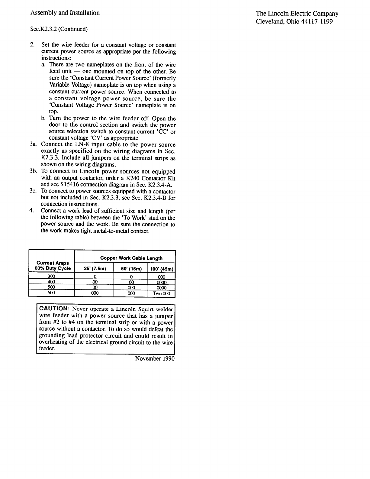
Lincoln arc welding and cutting
equipment is designed and built
with safety in mind. H oweve r,
your overall safety can be
increased by proper installation
... and thoughtful operation on
your part. DO NOT INS TALL,
OP ERAT E OR REPAIR T HIS
EQUIPMENT WITHOUT READING THIS MANUAL AND THE
SAFETY PRECAUTIONS CONTAINED THROUGHOUT. And,
most importantly, think bef
you act and be careful.
ore
TM
LN -8
IM274-A
June, 2010
Cleveland, Ohio 44117-1199 U.S.A. TEL: 216.481.8100 FAX: 216.486.1751 WEB SITE: www.lincolnelectric.com
OPERATOR’S MANUAL
Copyright © Lincoln Global Inc.
• World's Leader in Welding and Cutting Products •
• Sales and Service through Subsidiaries and Distributors Worldwide •
Page 2
i
SAFETY
i
WARNING
CALIFORNIA PROPOSITION 65 WARNINGS
Diesel engine exhaust and some of its constituents
are known to the State of California to cause cancer, birth defects, and other reproductive harm.
The Above For Diesel Engines
ARC WELDING CAN BE HAZARDOUS. PROTECT YOURSELF AND OTHERS FROM POSSIBLE SERIOUS INJURY OR DEATH.
KEEP CHILDREN AWAY. PACEMAKER WEARERS SHOULD CONSULT WITH THEIR DOCTOR BEFORE OPERATING.
Read and understand the following safety highlights. For additional safety information, it is strongly recommended that you
purchase a copy of “Safety in Welding & Cutting - ANSI Standard Z49.1” from the American Welding Society, P.O. Box
351040, Miami, Florida 33135 or CSA Standard W117.2-1974. A Free copy of “Arc Welding Safety” booklet E205 is available
from the Lincoln Electric Company, 22801 St. Clair Avenue, Cleveland, Ohio 44117-1199.
BE SURE THAT ALL INSTALLATION, OPERATION, MAINTENANCE AND REPAIR PROCEDURES ARE
PERFORMED ONLY BY QUALIFIED INDIVIDUALS.
The engine exhaust from this product contains
chemicals known to the State of California to cause
cancer, birth defects, or other reproductive harm.
The Above For Gasoline Engines
FOR ENGINE
powered equipment.
1.a. Turn the engine off before troubleshooting and maintenance
work unless the maintenance work requires it to be running.
____________________________________________________
1.b. Operate engines in open, well-ventilated
areas or vent the engine exhaust fumes
outdoors.
____________________________________________________
1.c. Do not add the fue l near an open f lame
welding arc or when the engine is running.
Stop the engine and allow it to cool before
refueling to prevent spilled fuel from vaporizing on contact with hot engine parts and
igniting. Do not spill fuel when filling tank. If
fuel is spilled, wipe it up and do not start
engine until fumes have been eliminated.
____________________________________________________
1.d. Keep all equipment safety guards, covers and devices in
position and in good repair.Keep hands, hair, clothing and
tools away from V-belts, gears, fans and all other moving
parts when starting, operating or repairing equipment.
____________________________________________________
1.e. In s ome cas es it may b e nec ess ary to remov e saf ety
gu a r d s to perf o r m r equir e d m ainten a n c e. Rem o v e
guards only when necessary and replace them when the
ma i n t e nance re q uirin g th eir re m o v a l is c o m p lete.
Always use the greatest care when working near moving
parts.
___________________________________________________
1.f. Do not put your hands near the engine fan.
Do not attempt to override the governor or
idler by pushing on the throttle control rods
while the engine is running.
1.h. To avoid scalding, do not remove the
radiator pressure cap when the engine is
hot.
ELECTRIC AND
MAGNETIC FIELDS
may be dangerous
2.a. Electric curr en t flowing through any conduct or c au ses
localized Electric and Magnetic Fields (EMF). Welding
current creates EMF fields around welding cables and
welding machines
2.b. EMF field s may int erfer e with some pacemak ers, and
welders having a pacemaker should consult their physician
before welding.
2.c. Exposure to EMF fields in welding may have other health
effects which are now not known.
2.d. All welders should use the following procedures in order to
minimize exposure to EMF fields from the welding circuit:
2.d.1.
Route the electrode and work cables together - Secure
them with tape when possible.
2.d.2. Nev er coil the e lectrod e lead around your body.
2.d.3. Do not place your body between the electrode and
work cables. If the electrode cable is on your right
side, the work cable should also be on your right side.
___________________________________________________
1.g. To prevent accidentally starting gasoline engines while
turning the engine or welding generator during maintenance
work, disconnect the spark plug wires, distributor cap or
magneto wire as appropriate.
2.d.4. Connect the work cable to the workpiece as close as
possible to the area being welded.
2.d.5. Do not work next to welding power source.
Page 3

ii
SAFETY
ii
ELECTRIC SHOCK can
kill.
3.a. The electrode and work (or ground) circuits
are electrically “hot” when the welder is on.
Do not touch these “hot” parts with your bare
skin or wet cloth in g. W ea r dr y, hole-free
gloves to insulate hands.
3.b. Insulate yourself from work and ground using dry insulation.
Make certain the insulation is large enough to cover your full
area of physical contact with work and ground.
In addition to the normal safety precautions, if welding
mu s t be p e rformed under elec t rically hazar d ous
conditions (in damp locations or while wearing wet
clothing; on metal structures such as floors, gratings or
scaffolds; when in cramped positions such as sitting,
kneeling or lying, if there is a high risk of unavoidable or
accidental contact with the workpiece or ground) use
the following equipment:
• Semiautomatic DC Constant Voltage (Wire) Welder.
• DC Manual (Stick) Welder.
• AC Welder with Reduced Voltage Control.
3.c. In semiautomatic or automatic wire welding, the electrode,
electrode reel, welding head, nozzle or sem ia ut om at ic
welding gun are also electrically “hot”.
3.d. Always be sure the work cable makes a good electrical
connection with the metal being welded. The connection
should be as close as possible to the area being welded.
3.e. Ground the work or metal to be welded to a good electrical
(earth) ground.
3.f.
Maintain the electrode holder, work clamp, welding cable and
welding machine in good, safe operating condition. Replace
damaged insulation.
3.g. Never dip the electrode in water for cooling.
3.h. Ne ver s imu ltane ous ly touch ele ctr ica lly “ hot ” par ts of
electrode holders connected to two welders because voltage
between the two can be the total of the open circuit voltage
of both welders.
3.i. When working above floor level, use a safety belt to protect
yourself from a fall should you get a shock.
3.j. Also see Items 6.c. and 8.
ARC RAYS can burn.
4.a. Use a shield with the proper filter and cover
plates to protect your eyes from sparks and
the rays of the arc when welding or observing
open arc welding. Headshield and filter lens
should conform to ANSI Z87. I standards.
4.b. Use suitable clothing made from durable flame-resistant
material to protect your skin and that of your helpers from
the arc rays.
4.c. Protect other nearby personnel with suitable, non-flammable
screening and/or warn them not to watch the arc nor expose
themselves to the arc rays or to hot spatter or metal.
FUMES AND GASES
can be dangerous.
5.a. Weldi ng may produce fume s and gases
hazardous to health. Avoid breathing these
fumes and gases. When welding , keep
your head out of the fume. Use enough
ventilation and/or exhaust at the arc to keep
fumes and gases away from the breathing zone. When
we l ding w ith e lectrod e s wh i ch r e quire special
ve n tilati on s uch as s tainles s or hard facing (se e
instru ctio ns on container or MSDS ) o r o n l ead or
cadmium plated steel and other metals or coatings
which produce highly toxic fumes, keep exposure as
low as possible and within applicable OSHA PEL and
ACGIH TLV limits using local exhaust or mechanical
ventilation. In confined spaces or in some circumst a nces, outd o ors, a r espira tor may be r equired .
Additional precautions are also required when welding
on galvanized steel.
5. b. The operation of welding fume control equipment is affected
by various factors including proper use and positioning of
the equipment, maintenance of the equipment and the specific welding procedure and application involved. Worker
exposure level should be checked upon installation and
periodically thereafter to be certain it is within applicable
OSHA PEL and ACGIH TLV limits.
5.c.
Do not weld in locations near chlorinated hydrocarbon
coming from degreasing, cleaning or spraying operations.
The heat and rays of the arc can react with solvent vapors
form phosgene, a highly toxic gas, and other irritating products.
5.d. Shielding gases used for arc welding can displace air and
caus e injur y or dea th. Alw ays use e nough v entilat ion,
especially in confined areas, to insure breathing air is safe.
vapors
to
5.e. Read and understand the manufacturer’s instructions for this
equipment and the consumables to be used, including the
ma t e r i al s a f e ty d a t a shee t (MSDS) an d fo llow yo u r
employer’s safety practices. MSDS forms are available from
yo u r weld i n g di s t r ibuto r or fr om th e ma n u f actur e r .
5.f. Also see item 1.b.
Page 4
iii
SAFETY
iii
WELDING and CUTTING
SPARKS can
cause fire or explosion.
6.a.
Remove fire hazards from the welding area.
If this is not possible, cover them to prevent
Re m e m b er th a t w eldin g s p arks a n d h ot
materials from welding can easily go through small cracks
an d o pen i ngs to adja cen t a reas . A voi d w eldi ng nea r
hydraulic lines. Have a fire extinguisher readily available.
6.b. Where compressed gases are to be used at the job site,
special precautions should be used to prevent hazardous
situations. Refer to “Safety in Welding and Cutting” (ANSI
Standard Z49.1) and the operating information for the
equipment being used.
6.c. When not welding, make certain no part of the electrode
circuit is touching the work or ground. Accidental contact
can cause overheating and create a fire hazard.
6.d. Do not heat, cut or weld tanks, drums or containers until the
proper steps have been taken to insure that such procedures
will not cause flammable or toxic vapors from substances
inside. They can cause an explosion even
been “cleaned”. For information, purchase “Recommended
Safe Practices for the
Co n t a i ners and Piping That Have Held Haza r d o u s
Substances”, AWS F4.1 from the American Welding Society
(see address above).
6.e. Vent hollow castings or containers before heating, cutting or
welding. They may explode.
Sparks and spatter are thrown from the welding arc. Wear oil
6.f.
free protective garments such as leather gloves, heavy shirt,
cuffless trousers, high shoes and a cap over your hair. Wear
ear plugs when welding out of position or in confined places.
Always wear safety glasses with side shields when in a
welding area.
6.g. Connect the work cable to the work as close to the welding
area as practical. Work cables connected to the building
framework or other locations away from the welding area
increase the possibility of t he w el di ng current passing
through lifting chains, crane cables or other alternate circuits. This can create fire hazards or overheat lifting chains
or cables until they fail.
6.h. Also see item 1.c.
the welding s pa rks fro m startin g a fire.
though
they have
Preparation
for Welding and Cutting of
CYLINDER may explode
if damaged.
7.a. Us e o n ly com p r e ssed g a s c ylind e r s
containing the correct shielding gas for the
pr o c e s s used a n d p r operl y o p e ratin g
re g u l a tors d e signe d f or t h e gas a n d
pressure used. All hoses, fittings, etc. should be suitable for
the application and maintained in good condition.
7.b. Alwa ys keep cyl inder s in an upr ight posit ion sec urely
chained to an undercarriage or fixed support.
7.c. Cylinders should be located:
• Away from areas where they may be struck or subjected to
physical damage.
• A safe distance from arc welding or cutting operations and
any other source of heat, sparks, or flame.
7.d. Never allow the electrode, electrode holder or any other
electrically “hot” parts to touch a cylinder.
7.e. Keep your head and face away from the cylinder valve outlet
when opening the cylinder valve.
7.f. Valve protection caps should always be in place and hand
tight except when the cylinder is in use or connected for
use.
7.g. Re ad and f oll ow the inst ruc tio ns on com pre sse d g as
cylinders, associated equipment, and CGA publication P-l,
“Precautions for Safe Handling of Compressed Gases in
Cylinders,” available from the Compressed Gas Association
1235 Jefferson Davis Highway, Arlington, VA 22202.
FOR ELECTRICALLY
powered equipment.
8.a. Turn off input power using the disconnect
switch at the fuse box before working on
the equipment.
8.b. Install equipment in accord ance with the U.S. National
Electrical Code, all local code s and the manufacturer’s
recommendations.
8.c. Ground the equipment in accordance with the U.S. National
Electrical Code and the manufacturer’s recommendations.
6.I. Read and follow NFPA 51B “ Standard for Fire Prevention
During Welding, Cutting and Other Hot Work”, available
from NFPA, 1 Batterymarch Park, PO box 9101, Quincy, Ma
022690-9101.
6.j. Do not use a welding power source for pipe thawing.
Refer to http://www.lincolnelectric.com/safety for additional safety information.
Page 5

iv
SAFETY
iv
PRÉCAUTIONS DE SÛRETÉ
Pour votre propre protection lire et observer toutes les instructions
et les précautions de sûreté specifiques qui parraissent dans ce
manuel aussi bien que les précautions de sûreté générales suivantes:
Sûreté Pour Soudage A L’Arc
1. Protegez-vous contre la secousse électrique:
a. Les circuits à l’électrode et à la piéce sont sous tension
quand la machine à souder est en marche. Eviter toujours
tout contact entre les parties sous tension et la peau nue
ou les vétements mouillés. Porter des gants secs et sans
trous pour isoler les mains.
b. Faire trés attention de bien s’isoler de la masse quand on
soude dans des endroits humides, ou sur un plancher
metallique ou des grilles metalliques, principalement dans
les positions assis ou couché pour lesquelles une grande
partie du corps peut être en contact avec la masse.
c. Maintenir le porte-électrode, la pince de masse, le câble
de soudage et la machine à souder en bon et sûr état
defonctionnement.
d.Ne jamais plonger le porte-électrode dans l’eau pour le
refroidir.
e. Ne jamais toucher simultanément les parties sous tension
des porte-électrodes connectés à deux machines à souder
parce que la tension entre les deux pinces peut être le
total de la tension à vide des deux machines.
f. Si on utilise la machine à souder comme une source de
courant pour soudage semi-automatique, ces precautions
pour le porte-électrode s’applicuent aussi au pistolet de
soudage.
2. Dans le cas de travail au dessus du niveau du sol, se protéger
contre les chutes dans le cas ou on recoit un choc. Ne jamais
enrouler le câble-électrode autour de n’importe quelle partie
du corps.
5. Toujours porter des lunettes de sécurité dans la zone de
soudage. Utiliser des lunettes avec écrans lateraux dans les
zones où l’on pique le laitier.
6. Eloigner les matériaux inflammables ou les recouvrir afin de
prévenir tout risque d’incendie dû aux étincelles.
7. Quand on ne soude pas, poser la pince à une endroit isolé de
la masse. U n cour t-circuit accidental peut provoquer un
échauffement et un risque d’incendie.
8. S’assurer que la masse est connectée le plus prés possible
de la zone de travail qu’il est pratique de le faire. Si on place
la masse sur la charpente de la construction ou d’autres
endroits éloignés de la zone de travail, on augmente le risque
de voir passer le courant de soudage par les chaines de levage, câbles de grue, ou autres circuits. Cela peut provoquer
des risques d’incendie ou d’echauffement des chaines et des
câbles jusqu’à ce qu’ils se rompent.
9. Assurer une ventilation suffisante dans la zone de soudage.
Ceci est particuliérement important pour le soudage de tôles
galvanisées plombées, ou cadmiées ou tout autre métal qui
produit des fumeés toxiques.
10. Ne pas souder en présence de vapeurs de chlore provenant
d’o pérations de d égraissage, nettoyage ou pist olage. La
chaleur ou les rayons de l’arc peuvent réagir avec les vapeurs
du solvant pour produire du phosgéne (gas fortement toxique)
ou autres produits irritants.
11. Pour obtenir de plus amples renseignements sur la sûreté,
voir le code “Code for safety in welding and cutting” CSA
Standard W 117.2-1974.
PRÉCAUTIONS DE SÛRETÉ POUR
3. Un coup d’arc peut être plus sévère qu’un coup de soliel,
donc:
a. Utiliser un bon masque avec un verre filtrant approprié
ainsi qu’un verre blanc afin de se protéger les yeux du rayonnement de l’arc et des projections quand on soude ou
quand on regarde l’arc.
b. Porter des vêtements convenables afin de protéger la
peau de soudeur et des aides contre le rayonnement de
l‘arc.
c. Proté ge r l’autre p er sonnel travaillant à p roximité au
soudage à l’aide d’écrans appropriés et non-inflammables.
4. Des gout tes de laitier en fusion sont émises d e l’arc de
soudage. Se protéger avec des vêtements de protection libres
de l’huile, tels que les gants en cuir, chemise épaisse, pantalons sans revers, et chaussures montantes.
LES MACHINES À SOUDER À
TRANSFORMATEUR ET À
REDRESSEUR
1. Relier à la terre le chassis du poste conformement au code de
l’électricité et aux recommendations du fabricant. Le dispositif
de montage ou la piece à souder doit être branché à une
bonne mise à la terre.
2. Autant que possible, I’installation et l’entretien du poste seront
effectués par un électricien qualifié.
3. Avant de faires des travaux à l’interieur de poste, la debrancher à l’interrupteur à la boite de fusibles.
4. Garder tous les couvercles et dispositifs de sûreté à leur
place.
Page 6

NOTES
Page 7
Page 8

Page 9

Page 10

Page 11

Page 12
Page 13
Page 14
Page 15
Page 16
Page 17
Page 18
Page 19
Page 20
Page 21
Page 22

Page 23

Page 24
Page 25

Page 26
Page 27
Page 28
Page 29
Page 30
Page 31

Page 32

Page 33

Page 34

Sec. K3.1.1
Introduction
Input power (115VAC, 2.5A) is supplied by the Power Source.
Duty Cycle: The amount of welding perfromed in a 10 minute period,
expressed nas a percentage.
Page 35

Page 36

Page 37

NOTES
Page 38

Page 39

Page 40

Page 41

Page 42

Page 43

Page 44

Page 45

Page 46

Page 47

Page 48

Page 49

Page 50

Page 51

Page 52

Page 53

Page 54

P-103-C, C.1
P-103-D, D.1
P-103-E, E.1, P-103-E.2
P-103-F, F.1
P-103-G, G.1
P-103-H, H.1
P-103-J, J.1
P-103-K, K.1
P-202-C, C.1, C.2, C.3
C.4, C.5, C.6
P-110-C, C.1
P-110-D, D.1
P-110-E, E.1
P-110-F, F.1, G, G.1
P-107-F.2, F.3
P-107-G, G.1
P-107-J
P-107-L
P-107-M
P-107-O, O.1
P-125-N, N.1
P-125-O, O.1
P-107-P
P-107-R
P-107-S, S.1
P-107-T
..............................................................................................
P-107-V.a, V.b
P-107-W, W.1
P-107-W.2a, W.2b
Page 55

P-28-H, J.b1
P-107-X
P-107-Y
P-110-Z
P-110-AA
P-110-AA
P-114-H
Order K202
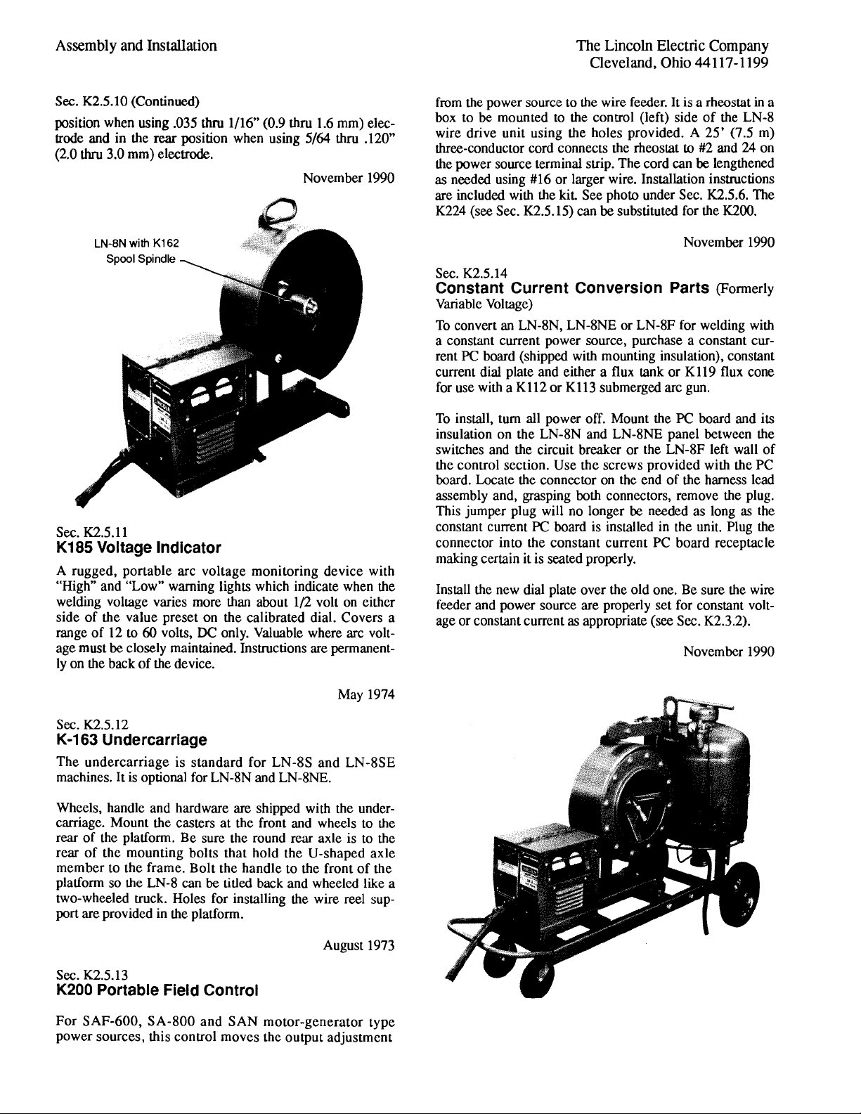
Order K162
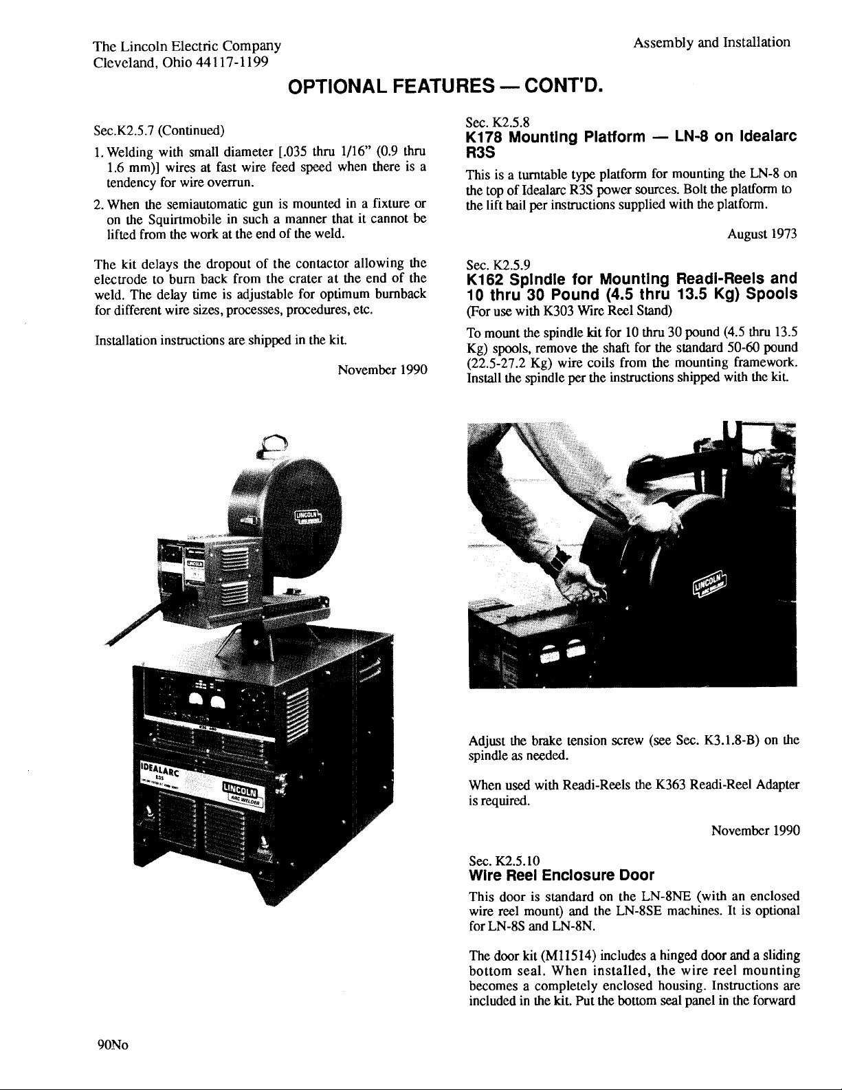
Order K178
Page 56

06-06-2005
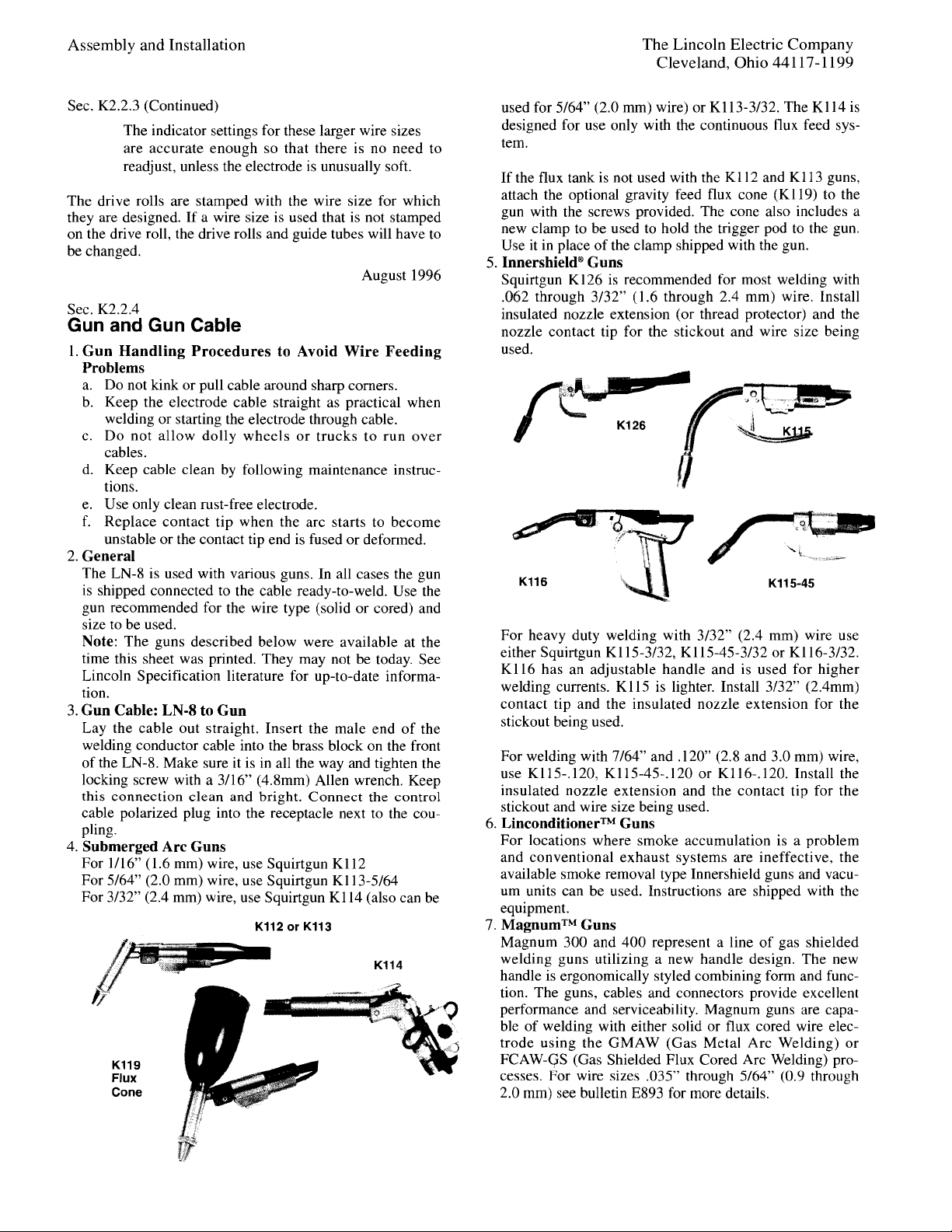
K112 & K113 SQUIRTGUNS & CABLES
P-103-CP-103-C
K112 & K113 Squirtguns & Cables
de o Gu s de o Gu s de o Gu s de o Gu s
Part Numbers Part Numbers Part Numbers Part Numbers
NOTE: In 1977 the semiautomatic guns were redesigned to conform to NEMA standards. To identify a new
design gun an ampere rating is stencilled on the clamp of the “Clamp and Tube Assembly” (Item 2). For
new design guns use columns 3 or 4. In 1979 the K112 and K113 guns were further redesigned. This latest redesign may be identified by a size molded in the nozzle insulation (Part of Item 1) near the handle to
gun connection.
1
7
8
9
10C10C
10D10D
5
4
2
6
3
1010
10A10A
10D10D
10B10B
Page 57

Gun & Cable Assembly (5/64” Electrode)
(No Electrode Size Stencil) K113 1 • • X •
Gun & Cable Assembly
(5/64” Electrode) (Stenciled 5/64)
K113-5/64 1 X • X •
Gun & Cable Assembly
(3/32” Electrode) (Stenciled 3/32)
K113-3/32 1 • • X •
1 Gun Assembly M10614-4
ø
1•X•X
1 Gun Assembly M10614-7 1 • • • X
1 Gun Assembly M10614-9 1 X • X •
1 Gun Assembly M10614-8 1 • • X •
Gun Parts See P-103-D
2 Clamp and Flux Tube Assembly S16165 1 X X X X
3 Handle M10102 1 X X • •
3 Handle M10102-1 1 • • X X
4 Socket Head Cap Screw T9447-9 1 X X • •
4 Socket Head Cap Screw T14438 1 • • X X
5 Trigger and Control Cable Assembly M12462-15 1 X X X X
Assembly Parts See P-103-K
6 8-32 x 1/4 Pan Head Screw CF000148 4 X X X X
7 Spatter Shield T12027 1 X X X X
8 Retaining Ring S9776-7 1 X X X X
9 Clamp S11598-1 1 X X • •
9 Clamp S15921-2 1 • • X X
10 Conductor Cable, Includes: L5728-7 1 • • X •
10 Conductor Cable, Includes: L4230-7 1 X • • •
10 Conductor Cable, Includes: L4230-1 1 • X • •
10 Conductor Cable, Includes: (350 Amp) L5728-1
ø
1•••X
10 Conductor Cable, Includes: (500 Amp) L6250-4 1 • • • X
10A Handle and Stiffener, Wire Feeder End M14048 1 X • X •
10A Handle and Stiffener, Wire Feeder End M14050-1 1 • X • X
10B Connector, Wire Feeder End S12801-6 X • X •
10B Connector, Wire Feeder End (350 Amp) S12801-1
ø
•X•X
10B Connector, Wire Feeder End (500 Amp) S12801-9 • • • X
10C Connector, Gun End (350 Amp) S12802-11 • • • X
10C Connector, Gun End (500 Amp) S12802-16 • • • X
10C Connector, Gun End S12802-6 X • • •
10C Connector, Gun End S12802-1 • X • •
10C Connector, Gun End S12802-14 • • X •
10D Clamping Tube, Both Ends (All Except 500A) S7748-40 2 X X X X
10D Clamping Tube, Both Ends (500A Only) S16997 2 • • • X
11
Cable Liner - For K112 (1/16” Electrode, 350 Amp Only)
S12898-5/64
ø
1•X••
Adapter Kit to use Squirtguns K113 with MN-1
and MN-3 (Not Illustrated) M10682
ø
1X•X•
Adapter Kit to use Squirtguns K113 with ML-2
(Not Illustrated) S12967
ø
1X•X•
11-22-2005
K112 & K113 SQUIRTGUNS & CABLES
Use only the parts marked “x” in the column under the
heading number called for in the model index page.
# Indicates a change this printing.
P-103-C.1
ITEM DESCRIPTION PART NO. QTY. 1 23456789
P-103-C.1
de o Gu s de o Gu s de o Gu s de o Gu s
Sub Assembly Illustration Sub Assembly Illustration Sub Assembly Illustration Sub Assembly Illustration
For Squirtgun K113, use the parts marked “X” in Column 1 or 3 (see note).
For Squirtgun K112, use the parts marked “X” in Column 2 or 4 (see note).
ø This part is obsolete and no longer available.
#
Page 58

06-03-2005
SQUIRTGUNS K112 & K113
P-103-D
P-103-D
Gun Assembly - Squirtguns K112 & K113
de o Gu s de o Gu s de o Gu s
Part Numbers Part Numbers Part Numbers Part Numbers
NOTE: In 1977 the semiautomatic guns were redesigned to conform to NEMA standards. To identify a
new design gun an ampere rating is stencilled on the clamp of the “Clamp & Tube Assembly”
(Item 2 of P-103-C). For new design guns use columns 3, 4 or 5. In 1979 the K112 and K113
guns were further redesigned. This latest redesign may be identified by a size molded in the
nozzle insulation (Part of Item 2) near the handle to gun connection.
1
2A
2B
4
3
2A1
2A2
2A3
2A4
5
2A
2B
2A1
2A2
2A3
2A4
Page 59

08-28-2007
SQUIRTGUNS K112 & K113
Use only the parts marked “x” in the column under the
heading number called for in the model index page.
# Indicates a change this printing.
P-103-D.1
ITEM DESCRIPTION PART NO. QTY. 123 4 56789
P-103-D.1
de o Gu s de o Gu s de o Gu s de o Gu s
Sub Assembly Illustration Sub Assembly Illustration Sub Assembly Illustration Sub Assembly Illustration
For Squirtgun K113, use the parts marked “X” in Column 1 or 3 (see note).
For Squirtgun K112, use the parts marked “X” in Column 2 or 4 (see note).
For Squirtgun K112 (500 Amp), use the parts marked “X” in Column 5 (see note).
ø This part is obsolete and no longer available.
1 Cap S12955 1 X X • • •
1 Cap T14181 1 • • X X X
2
Housing & Nozzle Asbly, Includes:
(5/64, Stenciled)
M10670-7 1 X • X • •
2
Housing & Nozzle Asbly, Includes:(
3/32, Stenciled)
M10670-6 1 • • X •
2 Housing & Nozzle Asbly, Includes: M10670-4
ø
1•X•X•
2 Housing & Nozzle Asbly, Includes: M10670-5 1 • • • • X
2A Nozzle S13813-1 1 • X • X X
2A Nozzle (3/32) S13813-3 1 • • X • •
2A Nozzle (5/64) S13813-4 1 • • X • •
2A1 Nozzle Liner, Tight Wound Steel Spring
(For 5/64, No Stencil) KP2095-1 1 X • X • •
2A1 Nozzle Liner, Tight Wound Steel Spring
(For 5/64 Stenciled) KP2095-12 1 • • X • •
2A1 Nozzle Liner, Tight Wound Steel Spring
(For 3/32 Stenciled) KP2095-11 1 • • X • •
2A1 Nozzle Liner, Tight Wound Steel Spring T12931-3 1 • X • X X
2A2 Ceramic Insert KP2094-2 1 • • X • •
2A3 Insert Retainer T12977-1 1 • • X • •
2A4 Hollow Lock Set Screw T12932-1 1 X X X X X
2B Housing S13486-1
ø
1•X•X•
2B Housing S13486-2 1 X • X • X
3 Collar S12964-1 1 X X X X X
4 Nozzle Flux Cone (S12957-1/2) KP1968-1 1 X X X X X
4 Nozzle Flux Cone (S12957-5/8) KP1968-5 1 X X X X X
4 Nozzle Flux Cone (S12957-3/4) KP1968-4 1 X X X X X
4 Nozzle Flux Cone (S12957-13/16) KP1968-2 1 X X X X X
4 Nozzle Flux Cone (S12957-15/16) KP1968-3 1 X X X X X
4 Chamfered 3/4” Nozzle Flux Cone T14278 1 X X X X X
5 Contact Tip, 1/16” Electrode T12011-1/16 KP2086-2 * • X • X •
5 Contact Tip, 5/64” Electrode T12011-5/64 KP2086-4 * X • X • •
5 Contact Tip, 3/32” Electrode T14050-3/32 (Note 1) T14050-3/32 * • • X • •
5 Contact Tip, 3/32” Electrode
T12011-3/32 (1) KP2086-3 (1)
••X••
5 Contact Tip, 1/16” Electrode T14050-1/16 (Note 1) T14050-1/16 * • • • • X
Nozzle Extension K113-5/64, 1-3/4 Stickout S13027-4 1 X • X • •
Nozzle Extension K113-3/32, 1-3/4 Stickout S13027-5 1 X • X • •
Nozzle Extension K113-3/32, 2-1/8 Stickout S13027-3 1 X • X • •
Guide Tips for Long Stickout Extensions K113-5/64
KP2104-2 1 X • X • •
Guide Tips for Long Stickout Extensions K113-3/32
KP2091-1 1 X • X • •
Guide Tips for Long Stickout Extensions K113-3/32
T14435-3/32 (1)
X•X••
* As Required
(1) To be used only when using S13027-5 extension
NOTE 1: When tip life is limited by tip being
fused over the use of T14726-[ ] tips
may result in a lower overall cost.
#
#
#
Page 60

07-18-2005
K114 SQUIRTGUN & CABLE
P-103-E
P-103-E
K114 Squirtgun & Cable
de o Gu s de o Gu s de o Gu s de o Gu s
Part Numbers Part Numbers Part Numbers Part Numbers
7
4
5
1
3
2020
4A4A
4B4B
2
1616
1313
1010
9
6
1717
1515
1414
1212
1818
1919
30A30A
8
3434
3333
31C31C
2626
3535
2727
2828
31B31B
31D31D
31A31A
30B30B
3030
3131
2929
3737
3636
4040
}
4141
4242
3939 3030
3838
3232
Page 61

Squirtgun & Cable K114
1 Nozzle Flux Cone 13/16” Opening (Opt)(S12957-13/16) KP1968-2 1 X
1 Nozzle Flux Cone 5/8” Opening (Std) (S12957-5/8) KP1968-5 1 X
1 Nozzle Flux Cone 3/4” Opening (Opt) (S12957-3/4) KP1968-4 1 X
1 Nozzle Flux Cone 15/16” Opening (Opt)(S12957-15/16) KP1968-3 1 X
2 Contact Tip (T12236-3/32) KP2088-2
As Reqʼd
X
2 Contact Tip (Optional) (T12236-5/64) KP2088-3 1 X
Gun Assembly, Includes: (Items 3 thru 20) L5757-A 1 X
3 Socket Head Cap Screw T9447-22 1 X
4 Nozzle, Includes: S13816 1 X
4A Nozzle Liner, Tight Wound Steel Spring T12931-2 1 X
4B Liner Locking Screw T12932-2 1 X
5 Gun Tube S13042 1 X
6 Right & Left Gun Mount L3828 1 X
7 Flux Shut Off Assembly S11686 1 X
8 Receptacle Clamp T11521 1 X
9 Spring T11514 1 X
10 Lever S11567-1 1 X
12 Pivot Pin T11546 1 X
13 Rivet T10167-1 1 X
14 Plain Washer S9262-39 1 x
15 Spring Clip S11685 1 X
16 Trigger S11569 1 X
17 Snap Ring S9776-16 1 X
18 Gun Hanger T11523 1 X
19 Roll Pin T9967-23 1 X
20 Collar S12964-1 1 X
Handle & Conductor Cable Asbly, Includes: (Items 26 thru 42)
L5757-B
26 Clamping Ring S12903 1 X
27 Tube Insulator T11584 1 X
28 Handle S11629 1 X
29 Flux Tube S11822 1 X
30 Control Cable, Includes: M9473 1 X
Micro Switch S12182-1 1 X
30A 3 Contact Receptacle, Gun End T11155-1 1 X
30B 5 Contact Receptacle, Wire End S12020-6 1 X
31 Conductor Cable, Includes: L5728-6 1 X
31A Handle & Stiffener, Wire Feeder End M14048 1 X
31B Connector, Wire Feeder End S12801-6 1 X
31C Connector, Gun End S12802-14 1 X
31D Clamping Tube, Both Ends S7748-40 2 X
32 #8-32 x 1.875 FHS CF000133 2 X
33 Socket Head Screw T9447-8 1 X
34 Snap Ring S9776-28 1 X
35 Socket Head Screw T9447-21 1 X
36 Switch Mounting Plate S11588 1 X
37 #8-32 x .50 RHS CF000033 3 X
38 Actuator T11527 1 X
39 Insulation T11522 3 X
40 #2-56 x .4375 RHS CF000135 2 X
08-28-2007
K114 SQUIRTGUN & CABLE
Use only the parts marked “x” in the column under the
heading number called for in the model index page.
# Indicates a change this printing.
P-103-E.1
ITEM DESCRIPTION PART NO. QTY. 123456789
P-103-E.1
de o Gu s de o Gu s de o Gu s de o Gu s
Sub Assembly Illustration Sub Assembly Illustration Sub Assembly Illustration Sub Assembly Illustration
Page 62

41 Lock Washer T9695-10 2 X
42 #2-56 HN CF000136 2 X
Nozzle Extension, 2-1/4” Stickout, (Not Shown) S12891-1 1 X
Housing S13028-1 1 X
Insert T12329-1 1 X
Tip T12328-3/32 1 X
Nozzle Extension, 3-1/4” Stickout, (Not Shown) S12891-2
ø
1X
Housing S13028-2 1 X
Insert T12329-2
ø
1X
Tip T12328-3/32 1 X
Adapter Kit to use Squirtgun K114 w/MN-1 & ML-3
(Not Shown) KP24A-62 1 X
Adapter Kit to use Squirtgun K114 w/ML-2
(Not Shown) S12967
ø
1X
09-25-2008
K114 SQUIRTGUN & CABLE
Use only the parts marked “x” in the column under the
heading number called for in the model index page.
# Indicates a change this printing.
P-103-E.2
ITEM DESCRIPTION PART NO. QTY. 123456789
P-103-E.2
de o Gu s de o Gu s de o Gu s de o Gu s
Sub Assembly Illustration Sub Assembly Illustration Sub Assembly Illustration Sub Assembly Illustration
ø This part is obsolete and no longer available.
#
Page 63

K114 SQUIRTGUN & CABLE
NOTES
de o Gu s de o Gu s de o Gu s de o Gu s
Page 64

07-16-2007
SQUIRTGUN & CABLE
P-103-F
P-103-F
K115 Squirtgun & Cable
de o Gu s de o Gu s de o Gu s de o Gu s
Part Numbers Part Numbers Part Numbers Part Numbers
NOTE 1: For old contact tips (length 7/8”)
used only with nozzles made before Fall 1968,
order: T12236 – .120
T12236 – 7/64”
T12236 – 3/32"
NOTE: In 1977 the semiautomatic guns were redesigned to conform to NEMA standards. To identify a new
design gun an ampere rating is stencilled on the “Switch Housing Clamp” (Item 14). For new design guns use
columns 5, 6, 7, 8, 9 or 10.
1
4
1717
7
1515
3
2
6
17A17A
17B17B
9
1111
9A9A
9B9B
9C9C
9D9D
1212
8
1414
5
1010
1
Page 65

Gun & Cable Asbly (82º Nozzle): .120 & 7/64 K115-.120* 1 X • • • X • • • • •
Gun & Cable Asbly (82º Nozzle): 3/32 Wire K115-3/32* 1 • X • • • X • • • •
Gun & Cable Asbly (82º Nozzle): 5/64 Wire K115-5/64* 1 • • • • • • • • X •
Gun & Cable Asbly (45ºNozzle): .
120 & 7/64 Wire
K115-45-.120* 1 • • X • • • X • • •
Gun & Cable Asbly (45º Nozzle): 3/32 Wire K115-45-3/32* 1 • • • X • • • X • •
Gun & Cable Asbly (45º Nozzle): 5/64 Wire K115-45-5/64* 1 • • • • • • • • • X
1 Conductor Cable, Includes:
L4230-5* or -10*
1 XXXX••••••
1 Conductor Cable, Includes:
L5728-5* or -10*
1••••XXXX••
1 Conductor Cable, Includes:
L5728-7* or -14*
1 • •••••••XX
Handle, Wire Feeder End M14048 1 X X X X X X X X X X
Connector, Wire Feeder End S12801-6 1 • • • • • • • • X X
Connector, Gun End S12802-4 1 X X X X • • • • • •
Connector, Gun End S12802-13 1 X X X X X X X X X •
Connector, Gun End S12802-14 1 • • • • • • • • X X
Clamping Tube, Both Ends S7748-40 2 X X X X X X X X X X
2 Snap Ring S9776-7 1 X X X X X X X X X X
3 Clamp S15921-1 1 X X X X X X X X X X
4 Clamp & Shield Assembly S12880 1 X X X X X X X X X X
5 #8-32 x .25 Pan Head Screw CF000148 4 X X X X X X X X X X
6 Spatter Shield T12027 1 X X X X X X X X X X
7 Socket Head Cap Screw T9447-9 1 X X X X • • • • • •
7 Socket Head Cap Screw T14438 1 • • • • X X X X X X
8 Handle M10102 1 X X X X • • • • • •
8 Handle M10102-1 1 • • • • X X X X X X
9 Nozzle (82º), Includes:
(M11474-.120) KP1907-1 1 X • • • X • • • • •
9 Nozzle (82º), Includes:
(M11474-3/32) KP1907-2 1 • X • • • X • • • •
9 Nozzle (82º), Includes:
(
M14027-82-5/64) KP1919-2
1 • •••••••X•
9 Nozzle (45º), Includes:
(M11510-.120) KP1910-1 1 • • X • • • X • • •
9 Nozzle (45º), Includes:
(M11510-3/32) KP1910-2 1 • • • X • • • X • •
9 Nozzle (45º), Includes: (
M14027-45-5/64) KP1919-1
1 • ••••••••X
9A
Nozzle Liner, Tight Wound Steel Spring (.120) (T12931-7)
KP2095-6 1 X • X • X • X • • •
9A
Nozzle Liner, Tight Wound Steel Spring (3/32) (T12931-5)
KP2095-5 1 • X • X • X • X • •
9A
Nozzle Liner, Tight Wound Steel Spring (5/64) (T12931-32)
KP2095-13 1 • • • • • • • • X X
9B Nozzle Insert (.120)
(T12576-3) KP2094-3 1 X • X • X • X • • •
9B Nozzle Insert (3/32)
(T12576-1) KP2094-1 1 • X • X • X • X • •
9B Nozzle Insert (5/64)
(T12576-1) KP2094-1 2 • • • • • • • • X X
9C Nozzle Insert Retainer T12977-2 1 X X X X X X X X • •
9D Liner Locking Screw T12932-2 1 X X X X X X X X X X
10 Trigger & Control Cable Assembly
M12462-10 or -15*
1 X XX XXXXXXX
Assembly Parts See P-103-K
11 Insulated Guide, 2-3/4” Electrical Stickout S12691-1 1 X X X X X X X X • •
11 Insulated Guide, 3-3/4” Electrical Stickout S12691-2 1 X X X X X X X X • •
11 Insulated Guide, 1-1/4” Electrical Stickout S13358 1 X X X X X X X X • •
12 Contact Tip (Length 1-1/8”) Note 1
(T14157-.120) KP2103-3 X • X • X • X • • •
12 Contact Tip (Length 1-1/8”) Note 1
(T14157-7/64) KP2103-6 X • X • X • X • • •
12 Contact Tip (Length 1-1/8”) Note 1
(T14157-3/32) KP2103-4 • X • X • X • X • •
12 Contact Tip (Length 1-1/8”) Note 1
(T14157-5/64) KP2103-5 • • • • • • • • X X
12 Contact Tip (Length 1-1/8”) Note 1 (T14157-072) KP2103-1 1 • • • • • • • • X X
14 Switch Housing Clamp S12339 1 X X X X • • • • • •
14 Switch Housing Clamp S15922-1 1 • • • • X X X X X X
15 Shield Mounting Block (Early Guns Only)
(Not Illustrated) T12385
ø
1 X XX XXXXX • •
17 #8-32 x 1.50 RHS CF000119 2 X X X X X X X X X X
17A Lock Washer T9695-3 2 X X X X X X X X X X
17B #8-32 HN CF000042 2 X X X X X X X X X X
18 CCC Decal (Not Shown) T13086-192 1 X X X X X X X X X X
Adapter Kit to use K115 Squirtgun with MN-1 & ML-3 (Not Shown)
M10682
ø
1 X XX XXXXXXX
Adapter Kit to use K115 Squirtgun with ML-2 (Not Shown)
S12967
ø
1 X XX XXXXXXX
08-28-2007
SQUIRTGUN & CABLE
For .120 & 7/64” Electrode Gun, use the parts marked “X” in Column 1, 3, 5 or 7.
For 3/32” Electrode Gun, use the parts marked “X” in Column 2, 4, 6 or 8.
For 5/64” Electrode Gun, use the parts marked “X” in Column 9 or 10
# Indicates a change this printing.
P-103-F.1
ITEM DESCRIPTION PART NO. QTY. 123 456789 10
P-103-F.1
de o Gu s de o Gu s de o Gu s de o Gu s
Sub Assembly Illustration Sub Assembly Illustration Sub Assembly Illustration Sub Assembly Illustration
#
#
#
#
#
#
#
#
#
#
#
Page 66

06-06-2005
K116 SQUIRTGUN & CABLE
P-103-G
P-103-G
K116 Squirtgun & Cable
de o Gu s6 de o Gu s de o Gu s de o Gu s
Part Numbers Part Numbers Part Numbers Part Numbers
Note: In 1977 the semiautomatic guns were redesigned to conform to NEMA standards. To identify a new
design gun an ampere rating is stencilled in the handle of “ Assembly” (Item 7). For new design guns use
columns 3 or 4.
NOTE 1: For old contact tips (length 7/8”) used only with
nozzles made before Fall 1968, order: T12236-.120
T12236-7/64”
T12236-3/32”
13
1
8
9
10
4C
4D
2
5
3
11
6
7
4
4D
4B
12
1D
1C
1B
1A
4A
4B
4D
4A
13
4D
4C
11
10
1A
1B
1C
1D
12
Page 67

Gun & Cable Assembly-.120” & 7/64” Electrode K116-.120* 1 X • X •
Gun & Cable Assembly - 3/32” Electrode K116-3/32* 1 • X • X
1 Nozzle, Includes: M11475-.120 1 X • X •
1 Nozzle, Includes: M11475 - 3/32 1 • X • X
1A Nozzle Liner, Tight Wound Steel Spring (T12931-8) KP2095-7 1 X • X •
1A Nozzle Liner, Tight Wound Steel Spring T12931-6
ø
1•X•X
1B Nozzle Insert (T12576-3) KP2094-3 1 X • X •
1B Nozzle Insert (T12576-1) KP2094-1 1 • X • X
1C Nozzle Insert Retainer T12977-2 1 XXXX
1D Liner Locking Screw T12932-2 1 XXXX
2 Switch Housing Clamp S12339-1 1 XXXX
3 Handle M10102 1 X X • •
3 Handle M10102-1 1 • • X X
4 15ʼ Conductor Cable, Includes: L5728-5* 1 XXXX
4 15ʼ Conductor Cable, Includes: L5728-10* 1 XXXX
4 10ʼ Conductor Cable, Includes: L4230-10* 1 X X • •
4 10ʼ Conductor Cable, Includes: L5728-10* 1 • • X X
4A Handle, Wire Feeder End M14048 1 XXXX
4B Connector, Wire Feeder End S12801-4 1 XXXX
4C Connector, Gun End S12802-4 1 X X • •
4C Connector, Gun End S12802-13 1 • • X X
4D Clamping Tube, Both Ends S7748-40 2 XXXX
5 8-32 x 1/4 Pan Head Screw CF000049 4 XXXX
6 Socket Head Screw S11604-9 2 XXXX
7 Handle & Control Cable Assembly - 15ʼ Length L5734-15*
ø
1 XXXX
7 Handle & Control Cable Assembly - 10ʼ Length L4189-10* 1 X X • •
7 Handle & Control Cable Assembly - 10ʼ Length L5734-10* 1 • • X X
Assembly Parts See P-103-H 1 • • X X
8 Spatter Shield T12027 1 XXXX
9 Snap Ring S9776-7 1 XXXX
10 Clamp S11598-1 1 X X • •
10 Clamp S15921-2 1 • • X X
11 Socket Head Cap Screw T9447-9 1 X X • •
11 Socket Head Cap Screw T14438 1 • • X X
12 Contact Tip (Length 1-1/8”) Note 1 (T14157-.120) KP2103-3
As Reqʼd
X• X•
12 Contact Tip (Length 1-1/8”) Note 1
(T14157-7/64) KP2103-6
As Reqʼd
X• X•
12 Contact Tip (Length 1-1/8”) Note 1 (T14157-3/32) KP2103-4
As Reqʼd
•X•X
13 Insulated Guide, 2-3/4” Electrical Stickout (S12691-1) KP1965-1 1 XXXX
13 Insulated Guide, 3-3/4” Electrical Stickout (S12691-2) KP1965-2 1 X • • •
13 Insulated Guide, 1-1/2” Electrical Stickout (S13358) KP1971-1 1 • X X X
Adapter Kit to Use K116 w/MN-1 & ML-3 (Not Shown)
M10682
ø
1 XXXX
Adapter Kit to Use K116 with ML-2 (Not Shown) S12967
ø
1 XXXX
08-28-2007
K116 SQUIRTGUN & CABLE
Use only the parts marked “x” in the column under the
heading number called for in the model index page.
# Indicates a change this printing.
P-103-G.1
ITEM DESCRIPTION PART NO. QTY. 123456789
P-103-G.1
de o Gu s de o Gu s de o Gu s de o Gu s
Sub Assembly Illustration Sub Assembly Illustration Sub Assembly Illustration Sub Assembly Illustration
For .120 & 7/64” Electrode Gun, use the parts marked “X” in Column 1 or 3 (See Note).
For 3/32” Electrode Gun, use the parts marked “X” in Column 2 or 4 (See Note)
ø This part is obsolete and no longer available.
#
#
#
#
#
#
* Specify 15ʼ or 10ʼ Cable as Appropriate
Page 68

08-26-2008
K116 SQUIRTGUN HANDLE & CONTROL CABLE
P-103-HP-103-H
K116 Squirtgun Handle & Control Cable
de o Gu s de o Gu s de o Gu s de o Gu s
Part Numbers Part Numbers Part Numbers Part Numbers
4
1
3
6
21
5
11
12
26
17
22
20
19
13A
25
7
24
10
9
13
13C
13B
8
15
14
16
13B
13C
13
13A
14
19
16
20
10
24
25
26
22
12
11
21
17
15
Page 69

Squirtgun Handle & Control Cable K116
Handle & Control Cable Assembly - 15ʼ Length L5734-15 1 X
Handle & Control Cable Assembly - 10ʼ Length L5734-10 1 X
Handle & Control Cable Assembly - 15ʼ Length L4189-15 1 X
Handle & Control Cable Assembly - 10ʼ Length L4189-10 1 X
1 Handle Mounting Bracket S12905 1 X
3 Socket Head Cap Screw T9447-36 2 X
4 Socket Head Cap Screw T9447-22 2 X
5 #8-32 x .5 RHS CF000033 12 X
6 Handle Pivot Block S12690 2 X
7 #8-32 x .625 FHS CF000147 2 X
8 Lock Washer T10441-1 2 X
9 Insulating Pad T12241 1 X
10 #8-32 x .5 FHS CF000146 3 X
11 Lock Washer T4291-A 2 X
12 #8-32 HN CF000042 2 X
13 Control Cable, Includes: 15ʼ Length M10427-15 1 X
13 Control Cable, Includes: 10ʼ Length M10427-10 1 X
13A Micro Switch T12485 1 X
13B Polarized Plug, Wire Feeder End S12020-6 1 X
13C Clamp at Plug S12024-1 1 X
14 Friction Bushing T12233 2 X
15 Handle Pivot Shaft T12239 1 X
16 Snap Ring S9776-25 2 X
17 Trigger Assembly S23982 [*] 1 X
19 Spring T12025 1 X
20 Trigger Mounting Block (Straight Pull Trigger) S12688 1 X
20 Trigger Mounting Block (Pivoting Trigger) M18910 1 X
21 Gun Shield L4188 1 X
22 #3-48 x .75 RHS CF000312 2 X
24 Handle S12687-1 1 X
25 Switch Insulation S14878 1 X
26 Roll Pin T9967-52 1 X
08-26-2008
K116 SQUIRTGUN HANDLE & CONTROL CABLE
# Indicates a change this printing.
P-103-H.1
ITEM DESCRIPTION PART NO. QTY. 123456789
P-103-H.1
de o Gu s de o Gu s de o Gu s de o Gu s
Sub Assembly Illustration Sub Assembly Illustration Sub Assembly Illustration Sub Assembly Illustration
[*] For earlier design “straight pull” (non-pivoting) trigger, contact Customer Service
for replacement parts
#
Page 70

06-06-2005
K126 SQUIRTGUN & CABLE
P-103-JP-103-J
K126 Squirtgun & Cable
de o Gu s de o Gu s de o Gu s de o Gu s
Part Numbers Part Numbers Part Numbers Part Numbers
Note: In 1977 the semiautomatic guns were redesigned to conform to Nema standards. To identify a new
design gun an ampere rating is stencilled on the “Clamp” (Item 12). For new design guns use column 2.
Note 1: For old contact tips (length 7/8”) used only
with nozzles made before Fall 1968, order:
T12011-5/64”
T12011-3/32”
T12011-.068
Note 2: When tip life is limited by tip being fused
over the use of T14726-[ ]
ø
tips may result in a
lower overall cost.
10
15
10A
10B
10C
10D
8
14
18
17
16
5
3
4
2C
2D
1
7
11
12
6
2
2A
2D
2B
ø This part is obsolete and no longer available.
12
2B
2D
2A
15
10
18
2D
2C
17
10B
10C
10D
10A
16
14
11
Page 71

Gun & Cable Assembly, Includes: K126* 1 X X
1 Handle M10102-1 1 • X
1 Handle M10102 1 X •
2 Conductor Cable, Includes: (15ʼ) L6250-1* 1 • X
2 Conductor Cable, Includes: (15ʼ) L4230-4* 1 X •
2 Conductor Cable, Includes: (10ʼ) L6250-2* 1 • X
2 Conductor Cable, Includes: (10ʼ) L4230-11* 1 X •
2A Handle & Stiffener, Wire Feeder End S13099 1 X X
2A Handle & Stiffener, Wire Feeder End M14050-1 1 • X
2B Connector, Wire Feeder End S12801-3 1 X X
2C Connector, Gun End S12802-12 1 • X
2C Connector, Gun End S12802-3 1 X •
2D Clamping Tube, Both Ends S16997 2 • X
2D Clamping Tube, Both Ends S7748-40 2 X •
3 Snap Ring S9776-7 1 X X
4 Clamp S15921-2 1 • X
4 Clamp S11598-1 1 X •
5 Spatter Shield T12027 1 X X
6 8-32 x 1/4 PHS CF000148 4 X X
7 Socket Head Cap Screw T14438 1 • X
7 Socket Head Cap Screw T9447-9 1 X •
8 Contact Tip, 5/64” Electrode
(Length 1-1/8”) Note 1 & 2
KP2100-4
As Reqʼd
XX
8 Contact Tip, 3/32” Electrode
(Length 1-1/8”) Note 1 & 2
KP2100-3
As Reqʼd
XX
8 Contact Tip, .068” & .072”
Electrode (Length 1-1/8”) Note 1 & 2
KP2100-1
As Reqʼd
XX
8 Contact Tip, .062” Electrode
(Length 1-1/8”) Note 2
KP2100-2
As Reqʼd
XX
10 Nozzle, Includes: (M11476) KP1909-1 1 X X
10A Nozzle Liner, Tight Wound Steel Spring (T12931-4) KP2095-4 1 X X
10B Nozzle Insert (T12576-2) KP2094-2 1 X X
10C Nozzle Insert Retainer T12977-1 1 X X
10D Liner Locking Screw T12932-1 1 X X
11 Trigger & Control Cable Assembly M12462* 1 X X
Assembly Parts See P-103-K 1 X X
12 Clamp S15922-1 1 • X
12 Clamp S12339 1 X •
13 Insulated Guide, 2-3/4” Electrical Stickout
(Optional)t
(Not Shown) T12315 1 X X
13 Insulated Guide, 2.00” Electrical Stickout
(Optional)
(Not Shown) S17217-1 1 X X
14 Heat Shield Assembly S13037 1 X X
15 Thread Protector, 3/4 to 1-1/2” Stickout (T12313) KP2089-1 1 X X
16 #8-32 x 1-1/2 Round Head Screw CF000119 4 X X
17 Lock Washer T9695-3 2 X X
18 #8-32 Hex Nut CF000042 2 X X
Adapter Kit to use K126 with MN-1 or ML-3 M10682
ø
1XX
Adapter Kit to use K126 with ML-2 S12967
ø
1XX
* Specify Length 15ʼ or 10ʼ as appropriate.
08-28-2007
K126 SQUIRTGUN & CABLE
Use only the parts marked “x” in the column under the
heading number called for in the model index page.
# Indicates a change this printing.
P-103-J.1
ITEM DESCRIPTION PART NO. QTY. 123456789
P-103-J.1
de o Gu s de o Gu s de o Gu s de o Gu s
Sub Assembly Illustration Sub Assembly Illustration Sub Assembly Illustration Sub Assembly Illustration
This part is obsolete and no longer available.
#
#
#
#
Page 72

P-103-K
suGoedsuGoedsuGoedsuGoed
Trigger & Control Cable Assembly
srebmuN traPsrebmuN traPsrebmuN traPsrebmuN traP
P-103-K
12
12A
13D
8
13B
13A
4
13C
1
2
9
7
5
3
TRIGGER & CONTROL CABLE ASSEMBLY
07-25-2006
Page 73

P-103-K.1
suGoedsuGoedsuGoedsuGoed
P-103-K.1
# Indicates a change this printing.
K183, K289 & K206 guns. Use the parts marked “X” in column 2 for
K264, K345, K355, & K361 guns.
.YTQ .ON TRAP NOITPIRCSED METI 1 2 3 4 5 6 7 8 9
Trigger & Control Cable Assembly, Includes: M12462-15ʼ 1 X •
Trigger & Control Cable Assembly, Includes: M12462-10ʼ 1 X X
Trigger & Control Cable Assembly, Includes: M12462-8ʼ 1 • X
XX158421ThctiwS orciM1
XX160701LgnisuoH2
XX1]*[ 28932SylbmessA reggirT3
XX12-96611TpmalC droC4
XX152021TgnirpS5
XX125-7699TniP lloR6
XX2213000FCSHR 57. x 84-3#7
XX187841SnoitalusnI hctiwS8
XX122-40611SwercS teS9
Use the parts marked “X” in column 1 for K112, K113, K115, K126,
12 Polarized Plug, Wire Feeder End,
(Not Shown) (Old Style)
S12020-6 1 X •
12 Polarized Plug, Wire Feeder End S12020-16 1 • X
12A Clamp at Polarized Plug (Old Style) (Not Shown) S12024-1 1 X •
X•14-42021SgulP deziraloP ta pmalCA21
XX175791S:sedulcnI ,tiK gulP dedloM
13A Connector Body NSS 1 X X
13B Connector Cover NSS 1 X X
13C Connector Pin NSS 2 X X
13D Insulating Washer NSS 1 X X
13E Strain Relief (Not Shown) NSS 1 X X
[*] For earlier design “straight pull” (non-pivoting) trigger, contact Service Department
for replacement parts.
Sub Assembly Illustration Sub Assembly Illustration Sub Assembly Illustration Sub Assembly Illustration
NSS - Not Sold Separately
TRIGGER & CONTROL CABLE ASSEMBLY
07-25-2006
Page 74

05-03-2010
MAGNUM
®
300 & 400 GMAW GUN
P-202-CP-202-C
Magnum 300 & 400 GMAW Gun
6
8
9
5
15
2A
2B
1
2C
2A
16A
3
17
16B
4
18
20
12
11
7
de o ag u Gu s de o ag u Gu s de o ag u Gu s de o ag u Gu s
Part Numbers Part Numbers Part Numbers Part Numbers
2A
2C
18
20
17
16B
15
2A
16A
2B
11
12
Page 75

Gun & Cable Assembly:
300 Amp-Specify cable length & wire size. K470-[ ] 1 X •
300 Amp-Specify cable length & wire size. K2951-[ ] 1 • X
400 Amp-Specify cable length & wire size. K471-[ ] 1 X •
**400 Amp-Specify cable length & wire size. K541-[ ] 1 X •
400 Amp-Specify cable length & wire size. K2952-[ ] 1 • X
1 Connector Assembly See P-202-C.2 1 X X
2A Gun Handle (Left & Right) G1927 1 X X
2B Pan Head Screw (for Handle) S18825-1 3 X X
2C Handle Nut (Knurled) S18773 3 X X
3 Trigger Assembly (Non Interlocking-Standard) S21002 1 X X
3 Trigger Assembly (Interlocking-Parts Order Only) S20677 * 1XX
4 Spring Boot Retainer (Gun End Only) S24719 1 X X
5 Connector Cover L7723 1 X X
6 Nut (Cable Handle) S18690 1 X X
7 Gun Tube Assembly
See Chart P-202-C.4 1 X •
7 Gun Tube Assembly
See Chart P-202-C.6 1 • X
8 Tail Piece M15607 1 X X
9 Gas Plug Assembly S18695 1 X X
11 Slip on Nozzle Insulator
See Chart P-202-C.4
1X•
11 Slip on Nozzle Insulator
See Chart P-202-C.6 1 • X
12 Gas Nozzle
See Chart P-202-C.4
1X•
12 Gas Nozzle
See Chart P-202-C.6 1 • X
15 Decal 300 Amp S18750-1 1 X X
15 Decal 400 Amp S18750-2 1 X X
16 Collar Assembly, Includes: S18831 1 X X
16A Collar S18830 1 X X
16B Set Screw S11604-46 1 X X
17 Hanger M15693 1 X X
18 Contact Tip
See Chart P-202-C.4 1X•
18 Contact Tip See Chart P-202-C.6 1 • X
20 Gas Diffuser
See Chart P-202-C.4
1X•
20 Gas Diffuser
See Chart P-202-C.6 1 • X
Items Not Shown:
Cable Liners
See Chart P-202-C.4 1X•
Cable Liners
See Chart P-202-C.6 1 • X
Options:
Magnum Connector Kits
See Chart P-202-C.4 1XX
Magnum Fast-Connect Gas Tube Kit (for K466-1) Order K481 1 X X
05-03-2010
MAGNUM
®
300 & 400 GMAW GUN
Use only the parts marked “x” in the column under the
heading number called for in the model index page.
# Indicates a change this printing.
P-202-C.1
ITEM DESCRIPTION PART NO. QTY. 123456789
P-202-C.1
*Trigger requires latest version of Gun Handles.
** Comes with 300 Amp Gun Tube
de o ag u Gu s de o ag u Gu s de o ag u Gu s de o ag u Gu s
Sub Assembly Illustration Sub Assembly Illustration Sub Assembly Illustration Sub Assembly Illustration
Page 76

05-03-2010
MAGNUM
®
300 & 400 GMAW GUN
P-202-C.2P-202-C.2
Connector Assembly
de o ag u Gu s de o ag u Gu s de o ag u Gu s de o ag u Gu s
Part Numbers Part Numbers Part Numbers Part Numbers
8
2
7
6
1
10
11
7
3
11
10
Page 77

Connector Assembly (300A/10ʼ Cable) L7773-1 1 X
Connector Assembly (300A/15ʼ Cable) L7773-2 1 X
Connector Assembly (400A/10ʼ Cable) L7773-3 1 X
Connector Assembly (400A/15ʼ Cable) L7773-4 1 X
Connector Assembly (300A/12ʼ Cable) L7773-5 1 X
Connector Assembly (400A/12ʼ Cable) L7773-6 1 X
Connector Assembly (400A/20ʼ Cable) L7773-7 1 X
Connector Assembly (400A/25ʼ Cable) L7773-8 1 X
Includes:
1 Incoming Connector Assembly S18789 1 X
2 Connector Nut (300 Amp) S18749-1 2 X
2 Connector Nut (400 Amp) S18749-2 2 X
3 Cable Handle L7725 1 X
4 Cable Assembly: (Includes 4A)
300 Amp, 10 Ft. Cable L7761-3 1 X
300 Amp, 12 Ft. Cable L7761-17 1 X
300 Amp, 15 Ft. Cable L7761-4 1 X
400 Amp, 10 Ft. Cable L7761-5 1 X
400 Amp, 12 Ft. Cable L7761-18 1 X
400 Amp, 15 Ft. Cable L7761-6 1 X
400 Amp, 20 Ft. Cable L7761-19 1 X
400 Amp, 25 Ft. Cable L7761-20 1 X
4A Terminal (For Mating Gun Connector End) S19492-1 2 X
5 Spring Boot S24676 2 X
6 Strain Relief Housing S18786 1 X
7 Strain Relief S18787 2 X
8 Gun Tube Connector Assembly, Includes: S18655 1 X
Gun Tube Connector M15635 1 X
Tube S18847 1 X
“O” Ring T13483-8 1 X
Nozzle Clamp S15921-2 1 X
Clamping Screw T14438 1 X
Retaining Ring S9776-7 1 X
9 Spring Boot Retainer S24678 1 X
10 Incoming End Nut (300 Amp) S23822-300 1 X
10 Incoming End Nut (400 Amp) S23822-400 1 X
11 Strain Relief Housing S24677 1 X
05-03-2010
MAGNUM
®
300 & 400 GMAW GUN
Use only the parts marked “x” in the column under the
heading number called for in the model index page.
# Indicates a change this printing.
P-202-C.3
ITEM DESCRIPTION PART NO. QTY. 123456789
P-202-C.3
de o ag u Gu s de o ag u Gu s de o ag u Gu s de o ag u Gu s
Sub Assembly Illustration Sub Assembly Illustration Sub Assembly Illustration Sub Assembly Illustration
Page 78

PARTS
MAGNUM®300 & 400 GMAW GUN
P-202-C.4P-202-C.4
CHART A
Contact Tips/ Part Number English Metric
Gas Diffuser (Industry Ref.) Wire Size Wire Size
Standard Duty KP14-25 or KP14-25-B100 .025” 0.6 mm
KP14-30 or KP14-30-B100 .030” 0.8 mm
KP14-35 or KP14-35-B100 .035” 0.9 mm
KP14-40 or KP14-40-B100 .040” 1.0 mm
KP14-45 or KP14-45-B100 .045” 1.2 mm
KP14-52 or KP14-52-B100 .052” 1.3 mm
KP14-116 or KP14-116-B100 1/ 16” 1.6 mm
KP14-564 or KP14-564-B100 5/64” 2.0 mm
KP14A-364 or KP14A-364-B100 3 /6 4A 1.2mm
Heavy D uty KP14H-35 or KP14H-35-B100 .035” 0.9 mm
KP14H-40 or KP14H-40-B100 .040” 1.0 mm
KP14H-45 or KP14H-45-B100 .045” 1.2 mm
KP14H-52 or KP14H-52-B100 .052” 1.3 mm
KP14H-116 or KP14H-116-B100 1/ 16 ” 1.6 mm
KP14H-564 or KP14H-564-B100 5/ 64 ” 2.0 mm
KP14AH-364 or KP14AH-364-B100 3/64”A 1.2 mm
KP14AH-116 or KP14AH-116-B100 1/16”A 1.6 mm
Tapered KP14T-25 or KP14T-25-B100 .025” 0.6 mm
KP14T-30 or KP14T-30-B100 .030” 0.8 mm
KP14T-35 or KP14T-35-B100 .035” 0.9 mm
KP14T-40 or KP14T-40-B100 .040” 1.0 mm
KP14T-45 or KP14T-45-B100 .045” 1.2 mm
KP14T-52 or KP14T-52-B100 .052” 1.3 mm
KP14T-116 or KP14T-116-B100
1/16” 1.6 mm
Notched KP2010-4B1 .035” 0.9mm
Aluminum -5B1 3/64” 1.2mm
Gas Diffuser Asbly.
KP54A or KP54A-B25 .025-5/64” 0.6-2.0 mm
Gas Diffuser Asbly.
KP2024-2 or -2B1 .025-.035” 0.6-0.9 mm
CHART B
Gas Nozzles/ Part Number English Metric
Insulator (Industry Ref.) I.D. Size I.D. Size
Adjustable Slip-On KP24A-62 .62” 15.9 mm
(Requires Nozzle KP24A-50 .50” 12.7 mm
Insulator Assembly)
Recessed Slip-On KP24A-62-SS .62” 15.9 mm
(Requires Nozzle KP24A-50-SS .50” 12.7 mm
Insulator Assembly) KP24A-37-SS .37” 9.5 mm
Nozzle Insulator KP34A or KP34A-B25 — —
Assembly
Fixed Nozzle KP23-37 .38” 9.5 mm
Tip Recessed .12 in. KP23-50 .50” 12.7 mm
(3 mm) for KP23-62 .62” 15.9 mm
Spray Transfer KP23-75 .75” 19.1 mm
KP23T-37 .37” 9.5mm
Fixed Nozzle (Heavy Duty) Tip
KP23H-62 .62” 15.9mm
Recessed .12 in. (3mm)
KP1954-2 .75” 19.1mm
Spray Transfer
Fixed Nozzle KP23-37F .38” 9.5 mm
Tip Flush for KP23-50F .50” 12.7 mm
Short-Circuiting KP23-62F .62” 15.9 mm
Transfer KP23-75F .75” 19.1 mm
Coarse Thread Nozzle
(1)
1/8” (3.2mm) Recess KP24CT-62-S .62” 16mm
1/8” (3.2mm) Recess KP24CT-75-S .75” 19mm
1/4” (6.4mm) Recess KP24CT-62-R .62” 16mm
1/4” (6.4mm) Recess KP24CT-75-R .75” 19mm
Coarse Thread KP34CT
——
Insulator Assembly
Gun Tube Insulator KP2169-1 — —
CHART D
Gun Tube Part Number
60° KP1928-1 (400 amp)
-2 (300 amp)
45° KP1929-1 (400 amp)
-2 (300 amp)
82° KP1941-1 (300, 400 amp)
CHART E
Connector Kits
(1)
Trigger Gas Tube
Product Feeder Power Lead and Connector
Number Type Connector Connector Fitting Tools
K466-1 Lincoln
(2)
4444
K466-2
Tweco Adapted
4——4
Lincoln 10 Series
K466-3 Miller 4 4 — 4
K466-4 Hobart 27 4 4 4 4
K466-5 L-Tec 4 4 — 4
Adapted
K466-6 Wirematic &
Power Mig 4 4 — 4
K466-7 Hobart 4 4 — 4
Series 2000
K466-8 Lincoln
(3)
4444
K466-9 SP100T and 4 4 — 4
Related Units
K466-10
Lincoln 10 Series
44—4
(1)
See Magnum 300 & 400 Parts Manual for part numbers.
(2)
Except LN8 or LN9 using 1/16 and larger electrodes.
(3)
LN8 or LN9 using 1/16 and larger electrodes.
(1)
Requires Coarse Thread Insulator Assembly.
05-03-2010
CHART C
Cable Liner Part Number English Metric
For Steel (Industry Ref.) Wire Size Wire Size
For 15 ft (4.5 m) KP44-3545-15 .035 - .045” 0.9-1.2 mm
and less KP44-116-15 .052 - 1/16” 1.3-1.6 mm
Trim to Fit KP44-564-15 1/16 - 5/64” 1.6-2.0 mm
KP42-25-15 .025-.030” 0.6-0.8 mm
For cables 25 ft KP44-3545-25 .035 - .045” 0.9-1.2 mm
(7.6 m) and less KP44-116-25 .052 - 1/16” 1.3-1.6 mm
Trim to Fit KP44-564-25 1/16 - 5/64ʼʼ 1.6-2.0 mm
Cable Liner Part Number English Metric
for Aluminum (Industry Ref.) Wire Size Wire Size
For 10 ft (3 m) KP1958-1 .030 - .035” 0.8-0.9 mm
Trim to Fit KP1958-5 .035 - 3/64” 0.9 - 1.2mm
KP1958-3 1/16” 1.6 mm
For 15 ft (4.5 m) KP1958-2 .030 - .035” 0.8-0.9 mm
Trim to Fit KP1958-6 .035 - 3/64” 0.9 - 1.2mm
KP1958-4 1/16” 1.6 mm
KP42N354515 .035 - 3/64” 0.9 - 1.2mm
KP1955-2 1/16” 1.6mm
de o ag u Gu s de o ag u Gu s de o ag u Gu s de o ag u Gu s
Page 79

PARTS
MAGNUM®300 & 400 GMAW GUN
Part No.
K466-1 Connector Kit (Lincoln Wire Feeders)
Gas Tubing T10642-127
Tubing Clamp (2 required) T13777-4
Connector Assembly, Includes: S18645
Set Screw S11604-51
Insulation Tube T7028-234
Gun Control Cable M15608
Hose Nipple T14557-7
Socket Key T11563-4
Wrench S18845
K466-2 Connector Kit (For Tweco Adapted
Feeders)
Connector Assembly, Includes: S18653
Set Screw S11604-51
“O” Ring (2 required) T13483-8
Socket Key T11563-4
Wrench S18845
Hair Spring Cotter Pin S19762
K466-3 Connector Kit (For Miller Feeders)
Connector Assembly (Miller), Includes: S19760
“O” Ring (2 required) T13483-8
Connector Cap Assembly (Miller), Includes: S19761
Set Screw S11604-51
Gun Control Assembly (Miller) M16325
Wrench S18845
Socket Key T11563-4
Liner Material - .045” (1.2 mm) maximum S18685-12
Liner Material - 1/16” (1.6 mm) maximum S18685-13
Liner Material - 5/64” (2.0 mm) maximum S18685-14
K466-4 Connector Kit (For Hobart Feeders)
Connector (Hobart) S19763
Connector Cap Assembly (Hobart), Includes: S19765
Set Screw S11604-51
Gun Control Assembly (Hobart) M16328
Wrench S18845
Socket Key T11563-4
Liner Material - .045” (1.2 mm) maximum S18685-15
Liner Material - 1/16” (1.6 mm) maximum S18685-16
Liner Material - 5/64” (2.0 mm) maximum S18685-17
Hose Nipple T14557-7
Tubing Clamps (2 required) T13777-4
Gas Tubing T10642-166
K466-5 Connector Kit (For L-Tec Adapted
Feeders)
Connector Assembly (L-Tec), Includes: S20044
Set Screw S11604-51
“O” Ring (2 required) T13483-8
Socket Key T11563-4
Wrench S18845
Gun Control Assembly (L-Tec) M16520
Part No.
K466-6 Connector Kit (Wirematic)
Connector Assembly, Includes: S18653
Set Screw S11604-51
“O” Ring (2 required) T13483-8
Gun Control Assembly M16325
Socket Key T11563-4
Wrench S18845
K466-7 Connector Kit (Hobart Series 2000)
Connector Assembly, Includes: S18653
Set Screw S11604-51
“O” Ring (2 required) T13483-8
Socket Key T11563-4
Wrench S18845
Gun Control Cable Assembly M18003
K466-8 Connector Kit (Lincoln Wire Feeders)
Gas Tubing T10642-127
Tubing Clamp (2 required) T13777-4
Connector Assembly, Includes: S18645-2
Set Screw S11604-51
Insulation Tube T7028-234
Gun Control Cable M15608
Hose Nipple T14557-7
Socket Key T11563-4
Wrench S18845
K466-9 Connector Kit (Lincoln SP100T, SP125
& SP170T)
Connector Assembly, Includes: S18653-2
Set Screw S11604-51
“O” Ring (2 required) T13483-8
Socket Key T11563-4
Wrench S18845
Gun Control Cable Assembly M18003
K466-10 Connector Kit (Lincoln 10 Series)
Connector Assembly, Includes: S18653
Set Screw S11604-51
“O” Ring (2 required) T13483-8
Socket Key T11563-4
Wrench S18845
Gun Control Cable M15608
PARTS LIST OF MAGNUM CONNECTOR KITS
P-202-C.5P-202-C.5
05-03-2010
de o ag u Gu s de o ag u Gu s de o ag u Gu s de o ag u Gu s
Page 80

de o Sub sse b es de o Sub sse b es de o Sub sse b es de o Sub sse b es
PARTS
MAGNUM®300 & 400 GMAW GUN
P-202-C.6P-202-C.6
05-03-2010
CHART A
Contact Tips/ Part Number English Metric
Gas Diffuser (Industry Ref.) Wire Size Wire Size
250A/350A
KP2744-035 or KP2744-035-B100
.035” 0.9 mm
KP2744-045 or KP2744-045-B100
.045” 1.2 mm
KP2744-052 or KP2744-052-B100
.052” 1.3 mm
KP2744-116 or KP2744-116-B100
1/16” 1.6 mm
KP2744-564 or KP2744-564-B100
5/64” 2.0 mm
450A/550A
KP2745-035 or KP2745-035-B100
.035” 0.9 mm
KP2745-045 or KP2745-045-B100
.045” 1.2 mm
KP2745-052 or KP2745-052-B100
.052” 1.3 mm
KP2745-116 or KP2745-116-B100
1/16” 1.6 mm
KP2745-564 or KP2745-564-B100
5/64” 2.0 mm
Gas Diffuser Asbly:
250A/350A Thread-On
KP2746-1 or KP2746-1-B25
250A/
350A Slip-On
KP2746-2 or KP2746-2-B25
450A/550A Thread-On
KP2747-1 or KP2747-1-B25
4
50A/550A Slip-On
KP2747-2 or KP2747-2-B25
CHART B
Gas Nozzles Part Number English Metric
(Industry Ref.) I.D. Size I.D. Size
250A/350A Thread-On
1/8” Recess KP2742-1-50R .50” 12.7 mm
KP2742-1-50R-B25 .50” 12.7 mm
KP2742-1-62R .625” 15.9 mm
KP2742-1-62R-B25 .625” 15.9 mm
Flush KP2742-1-50F .50” 12.7 mm
KP2742-1-50F-B25 .50” 12.7 mm
KP2742-1-62F .625” 15.9 mm
KP2742-1-62F-B25 .625” 15.9 mm
1/8” Stickout KP2742-1-50S .50” 12.7 mm
KP2742-1-50S-B25 .50” 12.7 mm
KP2742-1-62S .625” 15.9 mm
KP2742-1-62S-B25 .625” 15.9 mm
250A/350A Slip-On
1/8” Recess KP2742-2-50R .50” 12.7 mm
KP2742-2-50R-B25 .50” 12.7 mm
KP2742-2-62R .625” 15.9 mm
KP2742-2-62R-B25 .625” 15.9 mm
Flush KP2742-2-50F .50” 12.7 mm
KP2742-2-50F-B25 .50” 12.7 mm
KP2742-2-62F .625” 15.9 mm
KP2742-2-62F-B25 .625” 15.9 mm
1/8” Stickout KP2742-2-50S .50” 12.7 mm
KP2742-2-50S-B25 .50” 12.7 mm
KP2742-2-62S .625” 15.9 mm
KP2742-2-62S-B25 .625” 15.9 mm
450A/550A Thread-On
1/8” Recess KP2743-1-62R .625” 15.9 mm
KP2743-1-62R-B25 .625” 15.9 mm
KP2743-1-75R .75” 19.1 mm
KP2743-1-75R-B25 .75” 19.1 mm
Flush KP2743-1-62F .625” 15.9 mm
KP2743-1-62F-B25 .625” 15.9 mm
KP2743-1-75F .75” 19.1 mm
KP2743-1-75F-B25 .75” 19.1 mm
1/8” Stickout KP2743-1-62S .625” 15.9 mm
KP2743-1-62S-B25 .625” 15.9 mm
KP2743-1-75S .75” 19.1 mm
KP2743-1-75S-B25 .75” 19.1 mm
450A/550A Slip-On
1/8” Recess KP2743-2-62R .625” 15.9 mm
KP2743-2-62R-B25 .625” 15.9 mm
KP2743-2-75R .75” 19.1 mm
KP2743-2-75R-B25 .75” 19.1 mm
Flush KP2743-2-62F .625” 15.9 mm
KP2743-2-62F-B25 .625” 15.9 mm
KP2743-2-75F .75” 19.1 mm
KP2743-2-75F-B25 .75” 19.1 mm
1/8” Stickout KP2743-2-62S .625” 15.9 mm
KP2743-2-62S-B25 .625” 15.9 mm
KP2743-2-75S .75” 19.1 mm
KP2743-2-75S-B25 .75” 19.1 mm
CHART C (250/350/450 Amp)
Cable Liner Part Number English Metric
For Steel (Industry Ref.) Wire Size Wire Size
For 15 ft (4.5 m) KP44-3545-15 .035 - .045” 0.9-1.2 mm
and less KP44-116-15 .052 - 1/16” 1.3-1.6 mm
Trim to Fit KP44-564-15 1/16 - 5/64” 1.6-2.0 mm
KP42-25-15 .025-.030” 0.6-0.8 mm
For cables 25 ft KP44-3545-25 .035 - .045” 0.9-1.2 mm
(7.6 m) and less KP44-116-25 .052 - 1/16” 1.3-1.6 mm
Trim to Fit KP44-564-25 1/16 - 5/64ʼʼ 1.6-2.0 mm
Cable Liner Part Number English Metric
for Aluminum (Industry Ref.) Wire Size Wire Size
For 10 ft (3 m) KP1958-1 .030 - .035” 0.8-0.9 mm
Trim to Fit KP1958-5 .035 - 3/64” 0.9 - 1.2mm
KP1958-3 1/16” 1.6 mm
For 15 ft (4.5 m) KP1958-2 .030 - .035” 0.8-0.9 mm
Trim to Fit KP1958-6 .035 - 3/64” 0.9 - 1.2mm
KP1958-4 1/16” 1.6 mm
KP42N354515 .035 - 3/64” 0.9 - 1.2mm
KP1955-2 1/16” 1.6mm
CHART E
Gun Tube Part Number
60° KP2925-60 (300 Amp)
60° KP2926-60 (400 Amp)
CHART D
Insulators Part Number
250A/350A KP2773-2 or KP2773-2-B25
450A/550A KP2773-1 or KP2773-1-B25
Page 81

MAGNUM®300 & 400 GMAW GUN
NOTES
de o Sub sse b es de o Sub sse b es de o Sub sse b es de o Sub sse b es
Page 82

LN-8 WIRE FEED UNIT
(Except LN-8F)
P-110-CP-110-C
21 30 29 40
7
10
1
2
3
45
FRONT VIEW
17
18
34
24
41
39
12
SIDE VIEW BACK VIEW
33
19
32
152614
Par t Number s Par t Numbers Part Number s Par t Number s
11-86
L5741-B
11-14-86F
Page 83

1 Instrument Panel Assembly See P-110-D 1
2 Potentiometer T10812-71 1
3 Potentiometer Insulation T12792-1 2
4 Dial Plate (Constant Voltage) (Below Code 9900) M12229 1
5 Dial Plate (Variable Voltage) LN-8S & LN-8SE Only M12230 1
7 Nameplate (Below Code 7900) S14629 1
7 Nameplate (Above Code 7900) S16029 1
10 Base Assembly (Below Code 7575) M11467 1
10 Base Assembly (Code 7575 to 9100) L5778 1
10 Base Assembly (Above Code 9100) L5778-6 1
12 Wire Drive Motor & Gear Box Assembly
See Model Index
1
14 Door Assembly (Below Code 9000) M11490 1
14 Door Assembly (Between Code 9000 & 9900) M14850-1 1
14 Door Assembly (Above Code 9900) M14850-3 1
15 Cover Assembly (Below Code 9000) M12216 1
15 Cover Assembly (Between Code 9000 & 9900) M14851-1 1
15 Cover Assembly (Above Code 9900) M14851-4 1
Door Bumper (Above Code 9100) T14882 1
17 Hinge Pin M8809-53 1
18 Self Tapping Screw S8025-68 2
19 Warning Decal T13470 1
21 Plug Button T13597-2 1
22
Trimmer PC Board & Bracket Assembly (Code 7575 thru 7900)
(Not Illustrated) S15679
ø
1
Trimmer PC Board S15680 1
24
Door Cover Panel (Without Meters Only) (Below Code 9900)
M11662-2 1
24
Door Cover Panel (Without Meters Only) (Above Code 9900)
M11662-3 1
26 Drive Roll Decal S14140 1
27
Optional Meter Kits (Below Code 7575) (Not Illustrated)
See P-107-J or L
1
27
Optional Meter Kits (Above Code 7575) (Not Illustrated)
See P-110-A
29 Knob T10491 2
30 Potentiometer T10812-40 1
32
Grounding Lead Protector Assembly (Below Code 7900)
S15102
32
Grounding Lead Protector Assembly
(Above Code 7900 to 9100)
S15102-3 1
33 Resistor S10404-75 1
Round Head Screw #10-24 x 5.00 1
Insulating Washer T4479-A 2
34 Reset Decal T13086-4 1
35 Resistance Coil (Code 7900 to 9100) T14104 1
39 Roll Pin T9967-22 1
40 Warning Label M16196 1
41 Shunt Assembly M11502 1
Items Not Illustrated:
Collar Assembly (Drive Roll Mounting) T12341 1
Button Head Socket Screw (Drive Roll Mounting) T11551-6 1
Key (Drive Roll Mounting) M8776-31 1
Handle (Optional) S13863 1
07-19-2001
ITEM DESCRIPTION PART NO. QTY.
123456789
P-110-C.1P-110-C.1
# Indicates a Change This Printing
Sub As sembl y I l l ust r at i on Sub Assembl y I l l ust r at i on Sub Assembl y I l l ust r at i on Sub Assembl y I l l us t r at i on
ø This part is obsolete and no longer available.
Page 84

LN-8 INSTRUMENT PANEL ASSEMBLY
(All Models Except LN-8F Above Code 7575)
P-110-DP-110-D
5
11
18
17
16
14
13
4
9
19
8
1
2
3
4
Par t Number s Par t Numbers Part Number s Par t Number s
11-86
L5742
11-14-86G
NOTE: Obtain both item number and complete description for
parts listed. Some older operating manuals were printed with
item numbers which do not correspond with recent printings.
Page 85

1 Instrument Mounting Panel M12428-1 1 X X •
1 Instrument Mounting Panel M12428-2 1 • • X
2 Control P.C. Board Insulation (Above Code 7900) S15961 1 X X •
2 Control P.C. Board Insulation (Below Code 7900) S14819 1 X X X
3 Control P.C. Board (Above Code 7900) L5767-1 1 X X •
3 Control P.C. Board (Below Code 7900) L5040 1 X X X
Plastic Expansion Nut S14020-1 3 X X X
Self Tapping Screw S8025-14 3 X X X
4 Lead Clamp T13496-1 3 X X X
5 Decal (Below Code 7575 and Above Code 7900) T13086-1 1 X X X
5 Decal (Code 7575 thru 7900) T13086-15 1 X X •
8
Transformer & Receptacle Assembly (Above Code 7900)
S14165-140 1 X X •
8 Transformer Assembly (Below Code 7900) S14651-1
ø
1XXX
Transformer Insulation T14070 1 X X X
9 Relay P.C. Board Insulation (Above Code 7900) S14820-1 1 X X •
9 Relay P.C. Board Insulation (Below Code 7900) S14820
ø
1XXX
11 Relay P.C. Board (Above Code 8750) L5769-2 1 X X •
11* Relay P.C. Board (Code 7900 to 8750)
L5769 Note 1
1XX•
11* Relay P.C. Board (Below Code 7900) L5142-1 1 X X X
Relay S13929-9 1 X X X
Plastic Expansion Nut S14020-1 2 X X X
Self Tapping Screw S8025-14 2 X X X
13 Direction Switch T13495 1 X X X
14 Interlock Switch T10800-20 1 X X X
16 Variable Voltage P.C. Board Insulation S14818
ø
1•X•
17 Variable Voltage P.C. Board Assembly L5039-1 1 • X •
18 Circuit Breaker T12287-10 1 X X X
19 Decal T13086-3 1 X X •
Parts Not Illustrated (Below Code 7900 Only)
Unless Otherwise Specified:
Fuse Holder S10289 1 X X X
Fuse T10728-14 1 X X X
Identification Sticker T12607-14 1 X X X
Instrument Panel Mounting Bracket S14768 1 • • X
Output Polarized Plug (All Codes) S12021-3 1 X X •
Input Polarized Connector (All Codes) S12021-12 1 X X •
* For replacement of a Relay P.C. Board that has a
soldered-to-board relay, also order a relay.
Note 1: This P.C. Board can be replaced with the same
basic numbered P.C. Board with the same or
higher dash number.
01-31-2003
For LN-8N or NE use only the parts marked “X” in Column 1.
For LN-8S or SE use only the parts marked “X” in Column 2.
For LN-8F (Below Code 7575 Only) use only the parts marked “X” in Column 3.
ITEM DESCRIPTION PART NO. QTY.
123456789
P-110-D.1P-110-D.1
# Indicates a Change This Printing
Sub As sembl y I l l ust r at i on Sub Assembl y I l l ust r at i on Sub Assembl y I l l ust r at i on Sub Assembl y I l l us t r at i on
ø This part is obsolete and no longer available.
#
Page 86

LN-8F GENERAL ASSEMBLY
P-110-EP-110-E
1
3
5
8
6
7
Par t Number s Par t Numbers Part Number s Par t Number s
7-84
7-30-84
Page 87

1 Control Box (Above Code 7575) See P-110-F 1
1 Control Box Case (Below Code 7575 Only) L5126 1
Instrument Panel Assembly (Below Code 7575 Only)
See P-110-D 1
Instrument Panel Assembly (Above Code 7575) See P-110-G 1
Terminal Strip Assembly (With Leads) S14896-1 1
Number Plate T10726-83 1
5” Resistor S10404-75 1
Insulating Washer T4479-A 2
Round Head Screw, Resistor Mounting 10-24 x 5” 1
3 Decal T13086-3 1
5 Box Cover S14771 1
6 Dial Plate M12229 1
7 ʻVoltsʼ Potentiometer T10812-40 1
8 ʻAmpsʼ Potentiometer T10812-71 1
8 Potentiometer Knob T10491 2
Insulation T12792-1 2
LN-8 Nameplate S14629 1
Control Box to Wire Feed Unit Cable Assembly,
Not Illustrated, Includes: (Below Code 7900) L5156-15
ø
1
Control Box to Wire Feed Unit Cable Assembly,
Not Illustrated, Includes: (Above Code 7900) L5814-15 1
Control Cable, Includes: (Below Code 7900) L5156-B-15 1
Control Cable, Includes: (Above Code 7900) L5814-B-15 1
Female Polarized Plug (90°) S12022-8 1
Electrode Cable (Below Code 7900) L5156-C-15 1
Electrode Cable (Above Code 7900) L5814-C-15 1
Wire Feed Unit Assembly, Includes: (Below Code 7900)
M11813 1
Wire Feed Unit Assembly Includes: (Code 7900 to 8825)
M14508 1
Wire Feed Unit Assembly Includes: (Above Code 8825)
M11813-1 1
Wire Drive Assembly, Includes: (Below Code 7900)
L4477-3 1
Wire Drive Assembly, Includes: (Code 7900 to 8825)
L5744-2 1
Wire Drive Assembly, Includes: (Above Code 8825)
L6823-2 1
Wire Drive Assembly Parts
See Model Index
1
Connection Box Assembly, Includes: (Below Code 7900)
M11812 1
Connection Box Assembly, Includes: (Above Code 7900)
M11812-1 1
Connection Box L4825 1
Terminal Strip S14872-1 1
Number Plate (Below Code 7900) T10726-82
ø
Number Plate (Above Code 7900) T10726-120
ø
1
Box Cover T13193
Male Polarized Plug, Input S12021-1 1
Female Polarized Plug, Gun Control Cable S12021-3 1
Collar Assembly (Drive Roll Mounting) T12341 1
Button Head Socket Screw (Drive Roll Mounting)
T11551-6 1
Key (Drive Roll Mounting) M8776-31 1
08-09-2001
ITEM DESCRIPTION PART NO. QTY.
123456789
P-110-E.1P-110-E.1
# Indicates a Change This Printing
Sub As sembl y I l l ust r at i on Sub Assembl y I l l ust r at i on Sub Assembl y I l l ust r at i on Sub Assembl y I l l us t r at i on
#
#
ø This part is obsolete and no longer available.
#
Page 88

LN-8F CONTROL BOX
(Above Code 7575)
P-110-FP-110-F
2
1
6
19
34
8
25
3
35
22
28
17
16
11
20
18
21
Par t Number s Par t Numbers Part Number s Par t Number s
3-83
L5815
3-31-83P
Page 89

1 Control Box & Shunt Assembly, Includes: L5564
ø
1
Control Box L5563 1
Meter Shunt S15716 1
Insulation Sheet Under Shunt M13106 1
Insulating Tube, Shunt Mounting T7305-22 2
Insulating Washer, Shunt Mounting S10773-14 4
2 Box Cover (Below Code 9900) M13107
ø
1
2 Box Cover (Above Code 9900) M13107-1
ø
1
3 Door Cover Panel (Below Code 9900) M11662-2 1
3 Door Cover Panel (Above Code 9900) M11662-3 1
6 Instrument Panel Assembly See P-110-G 1
8 Resistor S10404-75 1
8 Round Head Screw #10-24 x 5.00 1
8 Insulation T4479-A 1
11 Nameplate (Code 7575 thru 7900) M13126 1
11 Nameplate (Above Code 7900) M13431 1
16 Interlock Switch T10800-20 1
17 Wire Direction Switch T13495 1
18 Dial Plate M13110 1
19 Warning Plate Decal T13470 1
20 Potentiometer T10812-71 1
Knob T10491 1
21 Insulation T12792-1 2
22 Potentiometer T10812-40 1
Knob T10491 1
25 Circuit Breaker T12287-10 1
28 Terminal Strip (Code 7575 thru 7900) S13323-2 1
28 Terminal Strip (Above Code 7900) S13323-6 1
Number Plate (Code 7575 thru 7900) T10726-113
ø
1
Number Plate (Above Code 7900) T10726-121
ø
1
29 Optional Meter Kits See P-110-A 1
34 Reset Decal T13086-2 1
35 Grounding Lead Protector S15102-3 1
Items Not Illustrated:
Input Polarized Connector S12021-12 1
08-09-2001
ITEM DESCRIPTION PART NO. QTY.
123456789
P-110-F.1P-110-F.1
# Indicates a Change This Printing
Sub As sembl y I l l ust r at i on Sub Assembl y I l l ust r at i on Sub Assembl y I l l ust r at i on Sub Assembl y I l l us t r at i on
ø This part is obsolete and no longer available.
#
Page 90

Instrument Panel Assembly, Includes: M13349 1 • X
Instrument Panel Assembly, Includes: M13109 1 X •
2 Insulation S15960 1 • X
2 Insulation S15712 1 X •
3 Control P.C. Board L5767 1 • X
3 Control P.C. Board L5040 1 X •
4 Trimmer P.C. Board S15680 1 X •
5 Relay P.C. Board (Above Code 8750) L5769-2 1 • X
5* Relay P.C. Board (Code 7900 to 8750)
L5769 Note 1
1•X
5* Relay P.C. Board L5142-1 1 X •
7 Transformer & Receptacle Assembly S14165-140 1 • X
8 Fuse Holder Block S10289 1 X •
8 Fuse T10728-14 1 X •
9 Relay S13929-6 1 X X
* For replacement of a Relay P.C. Board that has a
soldered-to-board Relay, also order an Item 9 Relay.
Note 1: This P.C. Board can be replaced with the same
basic numbered P.C. Board with the same or
higher dash number.
2-91
For codes 7575 thru 7900 use the parts marked “X” in column 1.
For codes above 7900 use the parts marked “X” in column 2.
ITEM DESCRIPTION PART NO. QTY.
123456789
P-110-GP-110-G
# Indicates a Change This Printing
3 4 6
5
8
9
7
2
10
Par t Number s Par t Number s Par t Number s Par t Number s
#
M13109
6-3-77B
LN-8F INSTRUMENT PANEL
(Above Code 7575 Only)
Page 91

NOTES
Page 92

GEAR BOX AND DRIVE MOTOR ASSEMBLY
(For LN-8 Codes between 7901 and 8815 & Above 9000 Only)
P-107-F.2P-107-F.2
22122201371110121315149
4561781916 18
25
28
31
24
27A
26
27B 27C 27D
MOTOR LEAD ORIENTATION
FOR NA-5R TYPE ASSEMBLIES
MOTOR LEAD ORIENTATION
FOR LN TYPE ASSEMBLIES
Par t Number s Par t Numbers Part Number s Par t Number s
M14310
11-5-82N
L5743
4-15-83R
Page 93

Wire Drive Motor & Gear Box Assembly, Includes:
(LN-8N & 8S) L5743-1 1
Wire Drive Motor & Gear Box Assembly, Includes:
(LN-8F) L5743-2 1
31 Gear Box Assembly, Includes: M14310-1 1
1 Gear Box G1221-3 1
2 Helical Reduction Gear S13440 1
3 Pinion Gear Shaft S13441 1
4 Woodruff Key #304 1
5 Retaining Ring T8856-2 1
6 Needle Bearing S10116-4 2
7 Drive Gear S13442 1
8 Drive Shaft S13445 1
9 Woodruff Key #404 1
10 Bearing M9300-7 2
11 Snap Ring S9776-31 2
12 Beveled Snap Ring S11910-1 1
13 Plain Washer S9262-47 1
14 Lock Washer E106A-16 1
15 Hex Head Screw 3/8-16 x .625 1
16 Shaft Seal T13097 1
17 Plain Washer S9262-94
18 Shim (.010 Thick) S9262-50
As Reqʼd
18 Shim (.002 Thick) S9262-73
As Reqʼd
19 Spacer T11116-3 1
20 Gear Box Cover S13453 1
21 Lock Washer T9695-1 4
22 Thread Forming Screw S9225-30 4
24 Motor Insulator M13479-1 1
25 Drive Motor Assembly, Includes: M13327-1 1
Drive Motor, Includes: M13312 1
Brush & Spring Assembly (Universal Motor) M12254-1F 2
Brush & Spring Assembly (Stature Motor) M13312-12 2
Brush Cap (Universal Motor) Early Design 7/8-27 THD
M9655-7A
ø
2
Brush Cap (Universal Motor) Present Design 3/4-27 THD
M9655-7B
ø
2
Brush Cap (Stature Motor) M13312-13 2
Pinion S15013-3 1
Roll Pin-Pinion T9967-33 1
26 Insulation (Not used on LN-8F) T13911 1
27A Screw Insulator T14058 3
27B Plain Washer S9262-3 3
27C Lock Washer T4291-A 3
27D Round Head Screw #8-32 x 1.125 3
31 Gear Box Assembly See Above 1
06-12-2001
ITEM DESCRIPTION PART NO. QTY.
123456789
P-107-F.3P-107-F.3
# Indicates a Change This Printing
Sub As sembl y I l l ust r at i on Sub Assembl y I l l ust r at i on Sub Assembl y I l l ust r at i on Sub Assembl y I l l us t r at i on
#
#
ø This part is obsolete and no longer available.
Page 94

WIRE DRIVE MECHANISM
P-107-GP-107-G
Par t Number s Par t Numbers Part Number s Par t Number s
10-22-97
7
3421
41
39
38
5
28
14
15
16
19
21
10 11 12 13
21
14
15
16
29
L6823
12-20-84J
Page 95

01-01-2007
For LN-6 use parts marked “X” in Column 1.
For LN-8N and 8S use parts marked “X” in Column 2.
For LN-8F use parts marked “X” in Column 2.
ITEM DESCRIPTION PART NO. QTY.
123456789
P-107-G.1P-107-G.1
# Indicates a Change This Printing
Sub As sembl y I l l ust r at i on Sub Assembl y I l l ust r at i on Sub Assembl y I l l ust r at i on Sub Assembl y I l l us t r at i on
1 Drive Motor & Gear Box Parts (Code 8815 to 9000) See P-110-H 1 • X X
1
Drive Motor & Gear Box Parts (Below Code 8815 & Above 9000) See P-107-F or F.2
1XXX
2 Compression Spring T10247-10 1
3 Yoke Setting Indicator T12689 1
4 Button Head Socket Screw T11551-1 1
5 Hollow Set Screw S11604-28 4 X X X
7 Reed Switch Energizer Assembly, Includes: S13920 1 X • •
7
Reed Switch Energizer Assembly, Includes: (Below Code 7900)
S14623 1 • X X
7
Reed Switch Energizer Assembly, Includes: (Above Code 7900)
S14623-1 1 • X X
Reed Switch S13913 1 X • •
Reed Switch (Below Code 7900) S14622 1 • X X
Reed Switch (Above Code 7900) S14622-1 1 • X X
8 Shunt Assembly (Not Illustrated) M11502 1 X X •
10 Button Head Socket Screw T11551-5 1 X X X
11 Pivot Pin (Below Code 8715) T12206-3 1 X X X
11 Pivot Pin (Above Code 8715) T12206-2 1 X X X
12 Yoke Assembly S13454 1 X X X
13 Hollow Set Screw (Below Code 8715) S11604-8 1 X X X
13 Hollow Set Screw (Above Code 8715) S11604-35
ø
1XXX
14 Hex Head Cap Screw 1/4-20 x 2.00 4 X X X
15 Lock Washer E106A-2 4 X X X
16 Plain Washer S9262-23 4 X X X
19 Incoming Conductor Block L6872-1 1 X X X
21 Locator Bushing T12189 2 X X X
28 Incoming Wire Guide T12272 1 X X X
29 Outgoing Conductor Block L6872-2 1 X X X
38 Gear Box Mounting Plate M11460 1 X X X
39 Gear Box Insulation M12137 1 X X X
41 Feed Unit Mounting Bracket (LN-8F Only) M12616 1 • • X
Thermostat (LN-8 Only Below Code 7900) (Not Illustrated)
T13359-1 1 • X X
* NOTE: These items are no longer part of assembly but they are
included with parts orders of entire assembly.
23 Button Head Socket Screw T11551-6 1 X X X
24 Collar Assembly T12341 1 X X X
26 Key M8776-31 1 X X X
NOTE: These items are not part of assembly and must be
purchased separately or in kit form.
9 Idle Roll Assembly See Table 1 X X X
22 Incoming Guide Tube See Table 1 X X X
25 Drive Roll and Gear Assembly See Table 1 X X X
27 Outgoing Guide Tube See Table 1 X X X
30 Outgoing Guide Insert See Table 1 X X X
WIRE
SIZE
.030 - .035S
.035A
.045
3/64A
.052
1/16S
1/16A
.068
5/64
3/32
7/64
.120
CONVERSION
KIT
KP502-0.35
KP503-.035A
KP502-.052
KP503-3/64A
KP502-.052
KP502-1/16
KP503-1/16A
KP502-3/32
KP502-3/32
KP502-3/32
KP502-.120
KP502-.120
ITEM
9
S12722-035
S17731-035
S12722-052
S17731-3/64
S12722-052
S12722-1/16
S17731-1/16
S12722-3/32
S12722-3/32
S12722-3/32
S12722-120
S12722-120
ITEM
22
S13492-035
S13492-035
S13492-052
S13492-052
S13492-052
S13492-1/16
S13492-1/16
S13492-3/32
S13492-3/32
S13492-3/32
S13492-120
S13492-120
ITEM
25
S13343-035
S17729-035
ø
S13343-052
NSS
S13343-052
S13343-1/16
S17729-1/16
ø
T12057-3/32
T12057-3/32
T12057-3/32
T12057-120
T12057-120
ITEM
27
S12548-035
S12548-035
S12548-052
S12548-052
S12548-052
S12548-1/16
S12548-1/16
S12554-3/32
S12554-3/32
S12554-3/32
S12554-120
S12554-120
ITEM
30
S12553-035
S12553-035
S12553-052
S12553-052
S12553-052
S12553-1/16
S12553-1/16
S12725-3/32
S12725-3/32
S12725-3/32
S12725-120
S12725-120
#
ø This part is obsolete and no longer available.
NSS
- Not sold separately.
Page 96

NOTES
Page 97

Meter Kit, Includes: Order K197 1
1 Meter Housing L4753 1
2 Meter Panel M11487 1
3 Ammeter M10485-4 1
4 Voltmeter M10486-3 1
5 Polarity Switch Plate T13096 1
6 Polarity Switch T13111 1
9 Shock Mounting T13003 4
11 Cable M11521 1
12 Lead Clip T12563-4 2
13 Self Tapping Screw S8025-12 1
18 Meter Guard S10509-60 1
Shunt (Not Illustrated) See P-107-G 1
02-27-2001
ITEM DESCRIPTION PART NO. QTY.
123456789
P-107-JP-107-J
# Indicates a Change This Printing
AMMETER-VOLTMETER KIT
AMPS VOLTS
1 2 3 4 5 6
18
12
9 12 11
Par t Numbers Part Number s Par t Number s Par t Number s
#
Page 98

Meter Kit, Includes: K207 1
1 Meter Housing L4753 1
2 Meter Panel M11487 1
3 Wire Feed Speed Meter M12653-1 1
4 Voltmeter M10486-3 1
5 Polarity Switch T13111 1
6 Polarity Switch Plate T13096 1
7 Toggle Switch T13381 1
8 Switch Plate T13096-1 1
13 Insulated Meter Shield M12663
ø
1
14 P.C. Board Insulation S15157
ø
1
15 P.C. Board Assembly S15158 1
16 Tubing
E2106/1:219-41
2
17 Lockwasher E106A-2 2
19 Meter Guard S10509-60 1
21 Calibration Tool T13660 1
01-22-2002
ITEM DESCRIPTION PART NO. QTY.
123456789
P-107-LP-107-L
# Indicates a Change This Printing
WIRE FEED SPEED METER-VOLTMETER KIT
1
7
8
19
13
14
17
20
16
15
2 3 4 5 6
21
REAR
VIEW
Par t Number s Par t Number s Par t Number s Par t Number s
ø This part is obsolete and no longer available.
#
Page 99

LN-6 Power Input Cable Assembly, Includes: K164* 1
Control Cable Assembly, Includes: L4700-B*
ø
1
Amphenol Connector (Female) S12020-11 1
Amphenol Connector (Male) S12020-12 1
Amphenol Connector Clamp S12024-2 2
Electrode Cable Assembly L4700-C* 1
LN-8 & LN-9 Power Input Assembly, Includes: K196* 1
Control Cable Assembly, Includes: L5027-B* 1
Amphenol Connector (Female) S12020-8 1
Amphenol Connector (Male) S12024-2 1
Electrode Cable Assembly L5027-C* 1
LN-6NE & LN-6SE Extension Cable Assembly, Includes:
M11518** 1
Control Cable Assembly, Includes: M11517** 1
Amphenol Connector (Female) S12020-11 1
Amphenol Connector (Male) S12023-3 1
Amphenol Connector Clamp S12024-2 2
Conductor Cable Assembly L4702** 1
LN-8NE, 8SE, 9NE & 9SE Extension Cable
Assembly Includes: M12220** 1
Control Cable Assembly, Includes: M12219** 1
Amphenol Connector (Female) S12020-8 1
Amphenol Connector (Male) S12023-2 1
Amphenol Connector Clamp S12024-2 2
Conductor Cable Assembly L4702** 1
Flux Hose, 22-1/2 Ft.
(Reqʼd. For All Submerged Arc Machines) T10642-82
ø 1
Flux Hose, 45 Ft.
(Reqʼd. For All Submerged Arc Machines) T10642-83 1
Electrode Cable, 22-1/2 Ft.
(Reqʼd. On All Machines Above 450 Amps) M5906-106 1
Electrode Cable, 45 Ft.
(Reqʼd. On All Machines Above 450 Amps) M5906-104 1
* Specify Cable Length and Maximum Current
Draw Thru Cable.
** Specify “ 22-1/2 Ft.” or “ 45 Ft.” as appropriate.
07-26-2005
ITEM DESCRIPTION PART NO. QTY.
123456789
P-107-MP-107-M
# Indicates a Change This Printing
INPUT CABLE AND EXTENSION CABLE ASSEMBLIES
ø This part is obsolete and no longer available.
Page 100

50 AND 60# WIRE REEL SUPPORT
P-107-OP-107-O
Par t Number s Par t Numbers Part Number s Par t Number s
07-26-2005
3 2
1
10
13
87654
987654
11
12
L4699
 Loading...