

Page 1
Operator’s Manual
RETURN TO MAIN MENU
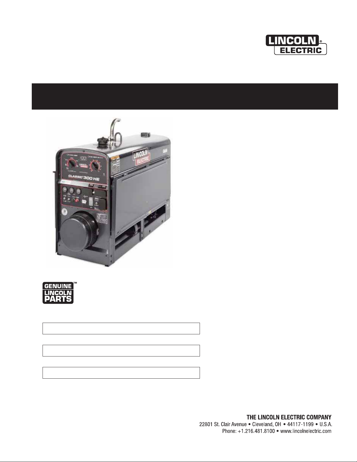
CLASSIC ®300 HE
For use with machines having Code Numbers:
11902
Save for future reference
Date Purchased
Code: (ex: 10859)
Serial: (ex: U1060512345)
IM10153 | Issue D ate Nov- 13
© Lincoln Global, Inc. All Rights Reserved.
Register your machine:
www.lincolnelectric.com/register
Authorized Service and Distributor Locator:
www.lincolnelectric.com/locator
Need Help? Call 1.888.935.3877
to talk to a Service Representative
Hours of Operation:
8:00 AM to 6:00 PM (ET) Mon. thru Fri.
After hours?
Use “Ask the Experts” at lincolnelectric.com
A Lincoln Service Representative will contact you
no later than the following business day.
For Service outside the USA:
Email: globalservice@lincolnelectric.com
Page 2
THANK YOU FOR SELECTING
AT ALL
TIMES.
SPECIAL SITUATIONS
Additional precautionary measures
A QUALITY PRODUCT BY
LINCOLN ELEC TRIC.
PLEASE EXAMINE CARTON AND EQUIPMENT FOR
DAMAGE IMMEDIATELY
When this equipment is shipped, title passes to the purchaser upon
receipt by the carrier. Consequently, Claims for material damaged in
shipment must be made by the purchaser against the transportation
company at the time the shipment is received.
SAFETY DEPENDS ON YOU
Lincoln arc welding and cutting equipment is designed and built with
safety in mind. However, your overall safety can be increased by
proper installation ... and thoughtful operation on your part.
DO NOT INSTALL, OPERATE OR REPAIR THIS EQUIPMENT
WITHOUT READING THIS MANUAL AND THE SAFETY PRECAUTIONS
CONTAINED THROUGHOUT. And, most importantly, think before you
act and be careful.
WARNING
This statement appears where the information must be followed
exactly to avoid serious personal injury or loss of life.
CAUTION
This statement appears where the information must be followed to
avoid minor personal injury or damage to this equipment.
KEEP YOUR HEAD OUT OF THE FUMES.
DON’T get too close to the arc. Use
corrective lenses if necessary to
stay a reasonable distance away
from the arc.
READ and obey the Material Safety
Data Sheet (MSDS) and the warning
label that appears on all containers
of welding materials.
USE ENOUGH VENTILATION or
exhaust at the arc, or both, to keep
the fumes and gases from your breathing zone and the general area.
IN A LARGE ROOM OR OUTDOORS, natural ventilation may be
adequate if you keep your head out of the fumes (See below).
USE NATURAL DRAFTS or fans to keep the fumes away from your
face.
If you de velop unusual symptoms, see your supervisor. Perhaps the
welding atmosphere and ventilation system should be checked.
WEAR CORRECT EYE, EAR & BODY PROTECTION
PROTECT your eyes and face with welding helmet
properly fitted and with proper grade of filter plate
(See ANSI Z49.1).
PROTECT your body from welding spatter and arc
flash with protective clothing including woolen
clothing, flame-proof apron and gloves, leather
leggings, and high boots.
PROTECT others from splatter, flash, and glare with
protective screens or barriers.
IN SOME AREAS, protection from noise may be
appropriate.
BE SURE protective equipment is in good condition.
Also, wear safety glasses in work area
DO NOT WELD OR CUT containers or materials which previously had
been in contact with hazardous substances unless they are properly
cleaned. This is extremely dangerous.
DO NOT WELD OR CUT painted or plated parts unless special
precautions with ventilation have been taken. They can release highly
toxic fumes or gases.
PROTECT compressed gas cylinders from excessive heat, mechanical
shocks, and arcs; fasten cylinders so they cannot fall.
BE SURE cylinders are never grounded or part of an electrical circuit.
REMOVE all potential fire hazards from welding area.
ALWAYS HAVE FIRE FIGHTING EQUIPMENT READY FOR
IMMEDIATE USE AND KNOW HOW TO USE IT.
Page 3

SECTION A:
Diesel Engines
Gasoline Engines
WARNINGS
CALIFORNIA PROPOSITION 65 WARNINGS
Diesel engine exhaust and some of its constituents are known
to the State of California to cause cancer, birth defects, and other
reproductive harm.
The engine exhaust from this product contains chemicals known
to the State of California to cause cancer, birth defects, or other
reproductive harm.
ARC WELDING CAN BE HAZARDOUS. PROTECT
YOURSELF AND OTHERS FROM POSSIBLE SERIOUS
INJURY OR DEATH. KEEP CHILDREN AWAY. PACEMAKER WEARERS SHOULD CONSULT WITH THEIR
DOCTOR BEFORE OPERATING.
Read and understand the following safety highlights. For additional
safety information, it is strongly recommended that you purchase a
copy of “Safety in Welding & Cutting - ANSI Standard Z49.1” from the
American Welding Society, P.O. Box 351040, Miami, Florida 33135 or
CSA Standard W117.2-1974. A Free copy of “Arc Welding Safety”
booklet E205 is available from the Lincoln Electric Company, 22801
St. Clair Avenue, Cleveland, Ohio 44117-1199.
BE SURE THAT ALL INSTALLATION, OPERATION,
MAINTENANCE AND REPAIR PROCEDURES ARE
PERFORMED ONLY BY QUALIFIED INDIVIDUALS.
SAFETY
1.d. Keep all equipment safety guards, covers and
devices in position and in good repair.Keep
hands, hair, clothing and tools away from
V-belts, gears, fans and all other moving parts
when starting, operating or repairing
equipment.
1.e. In some cases it may be necessary to remove safety guards to
perform required maintenance. Remove guards only when
necessary and replace them when the maintenance requiring
their removal is complete. Always use the greatest care when
working near moving parts.
1.f. Do not put your hands near the engine fan. Do not attempt to
override the governor or idler by pushing on the throttle control
rods while the engine is running.
1.g. To prevent accidentally starting gasoline engines while turning
the engine or welding generator during maintenance work,
disconnect the spark plug wires, distributor cap or magneto wire
as appropriate.
1.h. To avoid scalding, do not remove the radiator
pressure cap when the engine is
hot.
ELECTRIC AND
MAGNETIC FIELDS MAY
BE DANGEROUS
2.a. Electric current flowing through any conductor
causes localized Electric and Magnetic Fields (EMF). Welding
current creates EMF fields around welding cables and welding
machines
FOR ENGINE POWERED
EQUIPMENT.
1.a. Turn the engine off before troubleshooting
and maintenance work unless the
maintenance work requires it to be running.
1.b. Operate engines in open, well-ventilated
areas or vent the engine exhaust fumes outdoors.
1.c. Do not add the fuel near an open flame
welding arc or when the engine is running.
Stop the engine and allow it to cool before
refueling to prevent spilled fuel from
vaporizing on contact with hot engine parts
and igniting. Do not spill fuel when filling
tank. If fuel is spilled, wipe it up and do not start engine until
fumes have been eliminated.
2.b. EMF fields may interfere with some pacemakers, and welders
having a pacemaker should consult their physician before
welding.
2.c. Exposure to EMF fields in welding may have other health effects
which are now not known.
2.d. All welders should use the following procedures in order to
minimize exposure to EMF fields from the welding circuit:
2.d.1. Route the electrode and work cables together - Secure
them with tape when possible.
2.d.2. Never coil the electrode lead around your body.
2.d.3. Do not place your body between the electrode and work
cables. If the electrode cable is on your right side, the
work cable should also be on your right side.
2.d.4. Connect the work cable to the workpiece as close as possible to the area being welded.
2.d.5. Do not work next to welding power source.
3
Page 4
SAFETY
ELECTRIC SHOCK
CAN KILL.
3.a. The electrode and work (or ground) circuits are
electrically “hot” when the welder is on. Do
not touch these “hot” parts with your bare skin
or wet clothing. Wear dry, hole-free gloves to insulate hands.
3.b. Insulate yourself from work and ground using dry insulation.
Make certain the insulation is large enough to cover your full area
of physical contact with work and ground.
In addition to the normal safety precautions, if
welding must be performed under electrically
hazardous conditions (in damp locations or while
wearing wet clothing; on metal structures such as
floors, gratings or scaffolds; when in cramped
positions such as sitting, kneeling or lying, if there
is a high risk of unavoidable or accidental contact
with the workpiece or ground) use the following
equipment:
• Semiautomatic DC Constant Voltage (Wire) Welder.
• DC Manual (Stick) Welder.
• AC Welder with Reduced Voltage Control.
3.c. In semiautomatic or automatic wire welding, the electrode,
electrode reel, welding head, nozzle or semiautomatic welding
gun are also electrically “hot”.
3.d. Always be sure the work cable makes a good electrical
connection with the metal being welded. The connection should
be as close as possible to the area being welded.
3.e. Ground the work or metal to be welded to a good electrical (earth)
ground.
3.f. Maintain the electrode holder, work clamp, welding cable and
welding machine in good, safe operating condition. Replace
damaged insulation.
3.g. Never dip the electrode in water for cooling.
3.h. Never simultaneously touch electrically “hot” parts of electrode
holders connected to two welders because voltage
two can be the total of the open circuit voltage of both
welders.
3.i. When working above floor level, use a safety belt to protect
yourself from a fall should you get a shock.
between the
ARC RAYS CAN BURN.
4.a. Use a shield with the proper filter and cover plates to protect your
eyes from sparks and the rays of the arc when welding or
observing open arc welding. Headshield and filter lens should
conform to ANSI Z87. I standards.
4.b. Use suitable clothing made from durable flame-resistant material
to protect your skin and that of your helpers from the arc rays.
4.c. Protect other nearby personnel with suitable, non-flammable
screening and/or warn them not to watch the arc nor expose
themselves to the arc rays or to hot spatter or metal.
FUMES AND GASES
CAN BE DANGEROUS.
5.a. Welding may produce fumes and gases
hazardous to health. Avoid breathing these
fumes and gases. When welding, keep your head out of the fume.
Use enough ventilation and/or exhaust at the arc to keep fumes
and gases away from the breathing zone. When welding
with electrodes which require special ventilation
such as stainless or hard facing (see instructions
on container or MSDS) or on lead or cadmium
plated steel and other metals or coatings which
produce highly toxic fumes, keep exposure as low
as possible and within applicable OSHA PEL and
ACGIH TLV limits using local exhaust or
mechanical ventilation. In confined spaces or in
some circumstances, outdoors, a respirator may
be required. Additional precautions are also
required when welding on galvanized steel.
5. b. The operation of welding fume control equipment is affected by
various factors including proper use and positioning of the
equipment, maintenance of the equipment and the specific
welding procedure and application involved. Worker exposure
level should be checked upon installation and periodically
thereafter to be certain it is within applicable OSHA PEL and
ACGIH TLV limits.
5.c. Do not weld in locations near chlorinated hydrocarbon vapors
coming from degreasing, cleaning or spraying operations. The
heat and rays of the arc can react with solvent vapors to form
phosgene, a highly toxic gas, and other irritating products.
3.j. Also see It ems 6.c. and 8.
5.d. Shielding gases used for arc welding can displace air and
injury or death. Always use enough ventilation, especially in
confined areas, to insure breathing air is safe.
5.e. Read and understand the manufacturer’s instructions for this
equipment and the consumables to be used, including the
material safety data sheet (MSDS) and follow your employer’s
safety practices. MSDS forms are available from your welding
distributor or from the manufacturer.
5.f. Also see item 1.b.
4
cause
Page 5
SAFETY
WELDING AND CUTTING
SPARKS CAN CAUSE
FIRE OR EXPLOSION.
6.a. Remove fire hazards from the welding area. If
this is not possible, cover them to prevent the
welding sparks from starting a fire. Remember that welding
sparks and hot materials from welding can easily go through
small cracks and openings to adjacent areas. Avoid welding near
hydraulic lines. Have a fire extinguisher readily available.
6.b. Where compressed gases are to be used at the job site, special
precautions should be used to prevent hazardous situations.
Refer to “Safety in Welding and Cutting” (ANSI Standard Z49.1)
and the operating information for the equipment being used.
6.c. When not welding, make certain no part of the electrode circuit is
touching the work or ground. Accidental contact can cause
overheating and create a fire hazard.
6.d. Do not heat, cut or weld tanks, drums or containers until the
proper steps have been taken to insure that such procedures will
not cause flammable or toxic vapors from substances inside.
They can cause an explosion even though they have been
“cleaned”. For information, purchase “Recommended Safe
Practices for the Preparation for Welding and Cutting of
Containers and Piping That Have Held Hazardous Substances”,
AWS F4.1 from the American Welding Society (see address
above).
6.e. Vent hollow castings or containers before heating, cutting or
welding. They may explode.
6.f. Sparks and spatter are thrown from the welding arc. Wear oil free
protective garments such as leather gloves, heavy shirt, cuffless
trousers, high shoes and a cap over your hair. Wear ear plugs
when welding out of position or in confined places. Always wear
safety glasses with side shields when in a welding area.
6.g. Connect the work cable to the work as close to the welding area
as practical. Work cables connected to the building framework or
other locations away from the welding area increase the
possibility of the welding current passing through lifting chains,
crane cables or other alternate circuits. This can create fire
hazards or overheat lifting chains or cables until they fail.
6.h. Also see item 1.c.
CYLINDER MAY EXPLODE IF
DAMAGED.
7.a. Use only compressed gas cylinders containing
the correct shielding gas for the process used
and properly operating regulators designed for
the gas and pressure used. All hoses, fittings,
etc. should be suitable for the application and
maintained in good condition.
7.b. Always keep cylinders in an upright position securely chained to
an undercarriage or fixed support.
7.c. Cylinders should be located:
• Away from areas where they may be struck or subjected
to physical damage.
• A safe distance from arc welding or cutting operations
and any other source of heat, sparks, or flame.
7.d. Never allow the electrode, electrode holder or any other
electrically “hot” parts to touch a cylinder.
7.e. Keep your head and face away from the cylinder valve outlet
when opening the cylinder valve.
7.f. Valve protection caps should always be in place and hand tight
except when the cylinder is in use or connected for use.
7.g. Read and follow the instructions on compressed gas cylinders,
associated equipment, and CGA publication P-l, “Precautions for
Safe Handling of Compressed Gases in
Cylinders,” available
from the Compressed Gas Association 1235 Jefferson Davis
Highway, Arlington, VA 22202.
FOR ELECTRICALLY
POWERED EQUIPMENT.
8.a. Turn off input power using the disconnect
switch at the fuse box before working on the
equipment.
8.b. Install equipment in accordance with the U.S. National Electrical
Code, all local codes and the manufacturer’s recommendations.
6.I. Read and follow NFPA 51B “ Standard for Fire Prevention During
Welding, Cutting and Other Hot Work”, available from NFPA, 1
Batterymarch Park, PO box 9101, Quincy, Ma 022690-9101.
6.j. Do not use a welding power source for pipe thawing.
8.c. Ground the equipment in accordance with the U.S. National
Electrical Code and the manufacturer’s recommendations.
Refer to
http://www.lincolnelectric.com/safety
for additional safety information.
Welding Safety
Interactive Web Guide
for mobile devices
5
Page 6

SAFETY
PRÉCAUTIONS DE SÛRETÉ
Pour votre propre protection lire et observer toutes les instructions
et les précautions de sûreté specifiques qui parraissent dans ce
manuel aussi bien que les précautions de sûreté générales suivantes:
Sûreté Pour Soudage A LʼArc
1. Protegez-vous contre la secousse électrique:
a. Les circuits à lʼélectrode et à la piéce sont sous tension
quand la machine à souder est en marche. Eviter toujours
tout contact entre les parties sous tension et la peau nue
ou les vétements mouillés. Porter des gants secs et sans
trous pour isoler les mains.
b. Faire trés attention de bien sʼisoler de la masse quand on
soude dans des endroits humides, ou sur un plancher
metallique ou des grilles metalliques, principalement dans
les positions assis ou couché pour lesquelles une grande
partie du corps peut être en contact avec la masse.
c. Maintenir le porte-électrode, la pince de masse, le câble
de soudage et la machine à souder en bon et sûr état
defonctionnement.
d.Ne jamais plonger le porte-électrode dans lʼeau pour le
refroidir.
e. Ne jamais toucher simultanément les parties sous tension
des porte-électrodes connectés à deux machines à souder
parce que la tension entre les deux pinces peut être le
total de la tension à vide des deux machines.
f. Si on utilise la machine à souder comme une source de
courant pour soudage semi-automatique, ces precautions
pour le porte-électrode sʼapplicuent aussi au pistolet de
soudage.
6. Eloigner les matériaux inflammables ou les recouvrir afin de
prévenir tout risque dʼincendie dû aux étincelles.
7. Quand on ne soude pas, poser la pince à une endroit isolé de
la masse. Un court-circuit accidental peut provoquer un
échauffement et un risque dʼincendie.
8. Sʼassurer que la masse est connectée le plus prés possible
de la zone de travail quʼil est pratique de le faire. Si on place
la masse sur la charpente de la construction ou dʼautres
endroits éloignés de la zone de travail, on augmente le risque
de voir passer le courant de soudage par les chaines de levage, câbles de grue, ou autres circuits. Cela peut provoquer
des risques dʼincendie ou dʼechauffement des chaines et des
câbles jusquʼà ce quʼils se rompent.
9. Assurer une ventilation suffisante dans la zone de soudage.
Ceci est particuliérement important pour le soudage de tôles
galvanisées plombées, ou cadmiées ou tout autre métal qui
produit des fumeés toxiques.
10. Ne pas souder en présence de vapeurs de chlore provenant
dʼopérations de dégraissage, nettoyage ou pistolage. La
chaleur ou les rayons de lʼarc peuvent réagir avec les vapeurs
du solvant pour produire du phosgéne (gas fortement toxique)
ou autres produits irritants.
11. Pour obtenir de plus amples renseignements sur la sûreté,
voir le code “Code for safety in welding and cutting” CSA
Standard W 117.2-1974.
2. Dans le cas de travail au dessus du niveau du sol, se protéger
contre les chutes dans le cas ou on recoit un choc. Ne jamais
enrouler le câble-électrode autour de nʼimporte quelle partie
du corps.
3. Un coup dʼarc peut être plus sévère quʼun coup de soliel,
donc:
a. Utiliser un bon masque avec un verre filtrant approprié
ainsi quʼun verre blanc afin de se protéger les yeux du rayonnement de lʼarc et des projections quand on soude ou
quand on regarde lʼarc.
b. Porter des vêtements convenables afin de protéger la
peau de soudeur et des aides contre le rayonnement de
lʻarc.
c. Protéger lʼautre personnel travaillant à proximité au
soudage à lʼaide dʼécrans appropriés et non-inflammables.
4. Des gouttes de laitier en fusion sont émises de lʼarc de
soudage. Se protéger avec des vêtements de protection libres
de lʼhuile, tels que les gants en cuir, chemise épaisse, pantalons sans revers, et chaussures montantes.
5. Toujours porter des lunettes de sécurité dans la zone de
soudage. Utiliser des lunettes avec écrans lateraux dans les
zones où lʼon pique le laitier.
PRÉCAUTIONS DE SÛRETÉ POUR
LES MACHINES À SOUDER À
TRANSFORMATEUR ET À
REDRESSEUR
1. Relier à la terre le chassis du poste conformement au code de
lʼélectricité et aux recommendations du fabricant. Le dispositif
de montage ou la piece à souder doit être branché à une
bonne mise à la terre.
2. Autant que possible, Iʼinstallation et lʼentretien du poste seront
effectués par un électricien qualifié.
3. Avant de faires des travaux à lʼinterieur de poste, la debrancher à lʼinterrupteur à la boite de fusibles.
4. Garder tous les couvercles et dispositifs de sûreté à leur
place.
6
Page 7

TABLE OF CONTENTS
Page
Installation .......................................................................................................Section A
Technical Specifications ........................................................................................A-1
General Description...............................................................................................A-2
Design Features ....................................................................................................A-2
Pre-Operation Installation......................................................................................A-3
Safety Precautions ..........................................................................................A-3
Exhaust Spark Arrester ...................................................................................A-3
Location/Ventilation.........................................................................................A-3
Angle of Operation ..........................................................................................A-4
Machine Grounding.........................................................................................A-4
Lift Bail ............................................................................................................A-4
Trailers ............................................................................................................A-4
Vehicle Mounting.............................................................................................A-5
Polarity Control and Cable Sizes ....................................................................A-5
Pre-Operation Service ...........................................................................................A-5
Oil, Fuel...........................................................................................................A-5
Cooling System ...............................................................................................A-5
Battery Charging .............................................................................................A-6
Electrical Devices use with this Product..........................................................A-7
________________________________________________________________________
Operation .........................................................................................................Section B
Engine Operation...................................................................................................B-1
Starting The Kubota
Cold Weather Starting.....................................................................................B-1
High Altitude Operation ...................................................................................B-1
Stopping the engine, Engine Break-In.....................................................B-1, B-2
Welder Operation...................................................................................................B-2
Duty Cycle.......................................................................................................B-2
Control of Welding Current..............................................................................B-2
Idler Operation ................................................................................................B-3
Auxiliary Power, Fuel Consumption Data........................................................B-3
________________________________________________________________________
Accessories.....................................................................................................Section C
Optional Features (Field Installed) ........................................................................C-1
________________________________________________________________________
Maintenance ....................................................................................................Section D
Safety Precautions ................................................................................................D-1
General Instructions ..............................................................................................D-1
Cooling System .....................................................................................................D-1
Bearings ................................................................................................................D-1
Commutator and Brushes .....................................................................................D-1
Idler Maintenance..................................................................................................D-2
Nameplates ...........................................................................................................D-2
Purging Air from Fuel System................................................................................D-2
Engine Service Chart ............................................................................................D-3
GFCI Module Testing and Restting Procedure......................................................D-4
________________________________________________________________________
Troubleshooting..............................................................................................Section E
Safety Precautions.................................................................................................E-1
Welder Troubleshooting ........................................................................................E-2
Electronic Idler Troubleshooting Guide...........................................................E-3,E-4
Engine Troubleshooting Guide ...............................................................E-5 thru E-8
________________________________________________________________________
Diagrams ..........................................................................................................Section F
Wiring Diagrams ....................................................................................................F-1
Dimension Print......................................................................................................F-2
________________________________________________________________________
Parts List................................................................................................... P-734, Series
D1503-M
Engine ............................................................B-1
Page 8
A-1
INSTALLATION
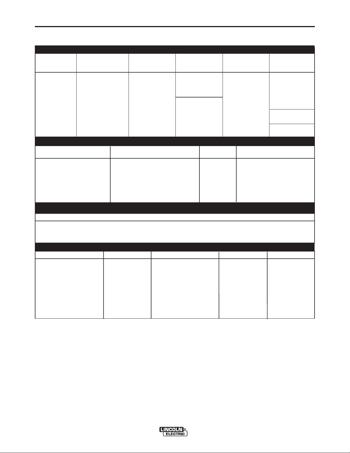
TECHNICAL SPECIFICATIONS - CLASSIC®300HE
INPUT - DIESEL ENGINE
Make/Model Description Speed (RPM) Displacement Starting Capacities
System
3 Cylinder
24.8HP (18.5kW) 91.47 cu. in
Naturally Aspirated (1.56 ltrs) (Group 24, 650
Kubota Water-Cooled High Idle 1800 cold crank amps)
D1503-M Diesel Engine Low Idle 1440 Bore x Stroke
EPA Tier 4 Cast Iron Cylinder, Full Load 1800 40 A. Alternator
Compliant Block/Crankcase 3.27” x 3.64” w/ built in reg.
88mm x 92.4mm
RATED OUTPUT @ 104°F(40°C) - WELDER
DESCRIPTION RATED DC OUTPUT* Duty DC CURRENT RANGE
VOLTS @ RATED AMPS CYCLE
300 Amp DC Welder 30V @ 250A 100% 160-240
All Copper Windings 32V @ 300A 60% 120-190
Pure DC Power Generator 90V DC Max. OCV @ 1800RPM 80-130
12VDC battery
1.4 KW
Starter
Fine Adjustments in each Range
Fuel:
16 gal.(60.6 L.)
Oil: 5.9 Qts., 5.6L
Coolant: 7.82 Qts. 7.4L
40-350 Amps
220-Max.
Min.-90
A-1
RATED OUTPUT @ 104°F(40°C) - GENERATOR
Auxiliary Power
3,000 Watts Continuous, 60 Hz AC
26 Amps @ 120V
13 Amps @ 240V
(1)
PHYSICAL DIMENSIONS
MODEL HEIGHT WIDTH DEPTH WEIGHT
K3198-1 CSA @ Without
Wire Feed Module
45.5 in.
(1156 mm) (616 mm) (1594 mm) (622kg)
(2)
24.3 in. 62.8 in. 1371lbs.
* Based on a 10 min. period.
(1)
Output rating in watts is equivalent to volt-amperes at unity power factor. Output voltage is within ± 10% at all loads up to
rated capacity. When welding, available auxiliary power will be reduced.
(2)
Height to top of exhaust elbow.
CLASSIC®300HE
Page 9

A-2
INSTALLATION
GENERAL DESCRIPTION
The Classic®300HE is a heavy duty, engine driven,
DC arc welding power source, capable of providing
constant current output for stick welding or DC TIG
welding. This welder is wound with all copper coils,
rated at 300 amps/32 Volts, and provides other
®
Classic
stainless hinges. With the addition of the optional
K3964-1 Wire Feed Module™, the Classic
will provide constant voltage output for running the
LN-7, LN-23P, or LN-25 wire feeders. The optional
K924-4 Remote Control Kit, provides a remote control
rheostat for remote fine current and open circuit voltage adjustment. See Section C for description.
The Classic
Protection System. In the event of sudden low oil
pressure or high coolant temperature, the engine
immediately shuts down. The Classic
current range of 40-350 DC amps with output ratings
as follows:
These units are also capable of providing 3 kVA of
120/240 volts of 60 cycle AC auxiliary power.
features such as improved door latches and
®
300HE
®
300HE has an Electronic Engine
®
300HE has a
RATED OUTPUT DUTY CYCLE
250A @ 30V
300A @ 32V
100%
60%
A-2
Engine Idler - The Classic®300HE is equipped with
an electronic automatic engine idler. It automatically
increases and decreases engine speed when starting
and stopping welding or using auxiliary power. A builtin time delay permits changing electrodes before the
engine slows to its low idle speed. The “Idler” control
switch on the panel locks the idler in high idle position
when desired.
Auxiliary Power - 3.0 kVA of nominal 120/240V,
60Hz, AC. Output voltage is maintained within ± 10%
at all loads up to rated capacity. (See Optional
Features for Power Plug Kit.)
GFCI - Protects the 20 amp, 120V duplex receptacle.
See the Maintenance Section for detailed information on testing and resetting of the GFCI.
120 V DUPLEX RECEPTACLE AND GFCI
A GFCI protects the 120V auxiliary power
receptacle.
A GFCI (Ground Fault Circuit Interrupter) is a device to
protect against electric shock should a piece of defective
equipment connected to it develop a ground fault. If this
situation should occur, the GFCI will trip, removing voltage from the output of the receptacle. If a GFCI is tripped
see the MAINTENANCE section for detailed information
on testing and resetting it. A GFCI should be properly
tested at least once every month.
®
The Classic
300HE uses the Kubota D1503M indus-
trial water-cooled diesel engine.
DESIGN FEATURES
Control Panel
The welder controls are located on the upper control
panel at the exciter end of the machine. The welder
controls consist of a five step “Current Range
Selector” switch and a “Fine Current Adjustment”
rheostat. The lower control panel is equipped with a
“Start” button, an “Ignition” switch, an “Idler” control
switch, and a “Glow Plug” button for easier cold
weather starting.
The lower control panel also contains an engine temperature gauge, a battery charging fault indicator, an
oil pressure gauge, a fuel/hour/led indicator gauge,
temperature gauge, For auxiliary power consists of
one 20 amp, 120VAC (5-20R) duplex receptacle with
GFCI protection and one 15 amp, 240VAC (6-15R)
receptacle, protected by 2 pole, 15 Amp breaker.
All Copper Windings - For long life and dependable
operation.
The 120 V auxiliary power receptacle should only be
used with three wire grounded type plugs or approved
double insulated tools with two wire plugs. The current
rating of any plug used with the system must be at least
equal to the current capacity of the associated receptacle.
CLASSIC®300HE
Page 10
A-3
Welder Enclosure - The complete welder is rubber
mounted on a rugged steel “C” channel base.
The output terminals are placed at the side of the
machines so that they are protected by the door. The
output terminals are labeled (+) and (-).
Cranking System - A 12 volt electric starter is standard.
Air Cleaner - Heavy duty two stage dry type.
Muffler - A muffler and stainless steel exhaust outlet
elbow are standard.
Fuel / Hour / LED gauge - A meter to record hours of
operation, show fuel status, battery charging fault LED
and engine fault LED.
Engine Protection - The system shuts the engine
down in the event of sudden low oil pressure or high
coolant temperature. A warning light on the control
panel will indicate such a fault. To reset the engine for
restarting, turn the ignition switch off then on. Refer to
Troubleshooting section for all warning light fault
codes.
Battery Charging Light - A warning indicator light for
Low/No battery charge. The light is off when the systems are functioning properly. The light will come on if
there is a Low/No battery condition but the machine
will continue to run.
INSTALLATION
A-3
PRE-OPERATION INSTALLATION
WARNING
Do not attempt to use this equipment until you
have thoroughly read the engine manufacturerʼs
manual supplied with your welder. It includes
important safety precautions, detailed engine
starting, operating and maintenance instructions,
and parts lists.
------------------------------------------------------------------------
ELECTRIC SHOCK can kill.
Do not touch electrically live parts or
•
electrode with skin or wet clothing.
• Insulate yourself from work and
ground
• Always wear dry insulating gloves.
------------------------------------------------------------------------
ENGINE EXHAUST can kill.
• Use in open, well ventilated areas or
vent exhaust outside.
------------------------------------------------------------------------
MOVING PARTS can injure.
•
Do not operate with doors open or
guards off.
• Stop engine before servicing.
• Keep away from moving parts.
------------------------------------------------------------------------
See additional warning information at the
front of this operatorʼs manual.
-----------------------------------------------------------
NOTE: The light will come on when the Run/Stop
switch is in the “ON” position. It will come on during
cranking and stay on until the engine starts. After,
starting the engine the light will go off unless a
Low/No battery condition exists.
Oil Drain Valve - A ball valve, hose and clamp are
standard.
Remote Control - The Remote / Local Switch and
Receptacle are standard.
EXHAUST SPARK ARRESTER
Some federal, state or local laws may require that
engines be equipped with exhaust spark arresters
when they are operated in certain locations where
unarrested sparks may present a fire hazard. The
standard muffler included with this welder does not
qualify as a spark arrester. When required by local
regulations, a suitable spark arrester must be installed
and properly maintained.
CAUTION
Use of an incorrect arrester may lead to engine damage
or performance loss. Contact the engine manufacturer
for specific recommendations.
------------------------------------------------------------------------
LOCATION / VENTILATION
Always operate the welder with the doors closed.
Leaving the doors open changes the designed air flow
and may cause overheating.
The welder should be located to provide an unrestricted flow of clean, cool air. Also, locate the welder so
that engine exhaust fumes are properly vented to an
outside area.
CLASSIC® 300HE
Page 11
A-4
INSTALLATION
ANGLE OF OPERATION
Engines are designed to run in the level condition which is
where the optimum performance is achieved. The maximum
angle of continuous operation is 20 degrees in all directions,
30 degrees Intermittent (less than 10 minutes continuous) in
all directions.
LIFT BAIL
A lift bail is provided for lifting with a hoist.
CAUTION
DO NOT MOUNT OVER COMBUSTIBLE SURFACES.
Where there is a combustible surface directly under stationary or fixed electrical equipment, the surface shall
be covered with a steel plate at least .06”(1.6mm) thick,
which shall extend not more than 5.90”(150mm) beyond
the equipment on all side.
-------------------------------------------------------------------------------
If the engine is to be operated at an angle, provisions must be
made for checking and maintaining the oil level at the normal
(FULL) oil capacity in the crankcase.
EQUIPMENT can damaged.
-------------------------------------------------------------------------------
A-4
WARNING
• Lift only with equipment of
adequate lifting capacity.
• Be sure machine is stable
when lifting.
• Do not lift this machine using
lift bale if it is equipped with a
heavy accessory such as trailer or gas cylinder.
FALLING • Do not lift machine if lift bale is
cause injury. • Do not operate machine while
suspended from lift bale.
When operating the welder at an angle, the effective fuel
capacity will be slightly less than the amount specified.
MACHINE GROUNDING
According to the United States National Electrical Code, the
frame of this portable generator is not required to be grounded
and is permitted to serve as the grounding means for cord
connected equipment plugged into its receptacle.
Some state, local, or other codes or unusual operating circumstances may require the machine frame to be grounded. It is
recommended that you determine the extent to which such
requirements may apply to your particular situation and follow
them explicitly. A machine grounding stud marked with the
symbol is provided on the welding generator frame foot. In
general, if the machine is to be grounded, it should be connected with a #8 or larger copper wire to a solid earth ground
such as a metal water pipe going into the ground for at least
ten feet and having no insulated joints, or to the metal framework of a building which has been effectively grounded. The
U.S. National Code lists a number of alternate means of
grounding electrical equipment.
TRAILER (See Optional Features)
If the user adapts a non-Lincoln trailer, the user must
assume responsibility that the method of attachment
and usage does not result in a safety hazard nor damage the welding equipment. Some of the factors to be
considered are as follows:
1. Design capacity of trailer vs. weight of Lincoln
2. Proper support of, and attachment to, the base of
3. Proper placement of the equipment on the trailer to
4. Typical conditions of use, i.e., travel speed, rough-
5. Conformance with federal, state and local laws.
equipment and likely additional attachments.
the welding equipment so there will be no undue
stress to the framework.
ensure stability side to side and front to back when
being moved and when standing by itself while
being operated or serviced.
ness of surface on which the trailer will be operated; environmental conditions, likely maintenance.
(1)
(1)
Consult your federal, state and local laws regarding specific
requirements for use on public highways.
CLASSIC®300HE
Page 12
A-5
INSTALLATION
A-5
VEHICLE MOUNTING
WARNING
Improperly mounted concentrated loads may
cause unstable vehicle handling and tires or other
components to fail.
• Only transport this Equipment on serviceable
vehicles which are rated and designed for such
loads.
• Distribute, balance and secure loads so vehicle
is stable under conditions of use.
• Do not exceed maximum rated loads for components such as suspension, axles and tires.
• Mount equipment base to metal bed or frame of
vehicle.
• Follow vehicle manufactureʼs instructions.
-------------------------------------------------------------------------------
POLARITY CONTROL AND CABLE SIZES
With the engine off, route the electrode and work
cables through the strain relief bracket on the base
and connect to the studs located below the fuel tank
mounting rail. (See size recommendations below.)
For positive polarity, connect the electrode cable to
the terminal marked “+”. For Negative polarity, connect the electrode cable to the “-” stud. These connections should be checked periodically and tightened
if necessary.
When welding at a considerable distance from the
welder, be sure you use ample sized welding cables.
RECOMMENDED COPPER CABLE SIZES
Cables Sizes for Combined Length
of Electrode Plus Work Cable
PRE-OPERATION SERVICE
CAUTION
READ the engine operating and maintenance
instructions supplied with this machine.
WARNING
• Stop engine while fueling.
• Do not smoke when fueling.
• Keep sparks and flame away from
tank.
• Do not leave unattended while
fueling.
• Wipe up spilled fuel and allow
DIESEL FUEL
can
cause fire
DIESEL FUEL ONLY-Low sulphur fuel or ultra low
sulphur fuel in U.S.A. and Canada.
-------------------------------------------------------------------------
OIL
This unit is supplied from the factory with the engine
crankcase filled with a high quality SAE 10W/30 oil.
This oil should be acceptable for most typical ambient
temperatures. Consult the engine operation manual
for specific engine manufacturerʼs recommendations.
Upon receipt of the welder, check the engine dipstick
to be sure the oil is at the “full” mark. DO NOT overfill.
FUEL
fumes to clear before starting
engine.
• Do not overfill tank, fuel expansion may cause overflow.
Amps Duty Cycle Up to 200ft.(61m) 200 to 250ft.
(61 to 76m)
250 100% 1 1/0
300 60% 1/0 2/0
CLASSIC®300HE
Fill the fuel tank with the grade of fuel recommended
in the Engine Operatorʼs manual. Make sure the valve
on the water separator is in the open position.
COOLING SYSTEM
The radiator has been filled at the factory with a 50-50
mixture of ethylene glycol antifreeze and water.
Check the radiator level and add a 50-50 solution as
needed (see engine manual or antifreeze container for
alternate antifreeze recommendations).
Page 13

A-6
INSTALLATION
BATTERY CHARGING
WARNING
GASES FROM BATTERY can explode.
• Keep sparks, flame and cigarettes
away.
BATTERY ACID can burn eyes and
skin.
• Wear gloves and eye protection and
be careful when boosting, charging or
working near battery.
To prevent EXPLOSION when:
a) Installing a new battery - disconnect the
negative cable from the old battery first and
connect the negative cable to the new battery
last.
b) Connecting a battery charger - remove the
battery from the welder by disconnecting the
negative cable first, then the positive cable and
battery clamp. When reinstalling, connect the
negative cable last.
c) Using a booster - connect the positive lead to
the battery first, then connect the negative lead to
the ground lead on the base.
A-6
To prevent ELECTRICAL DAMAGE when:
a) Installing a new battery.
b) Using a booster.
Use correct polarity - Negative Ground.
• To prevent BATTERY DISCHARGE, if you have an
ignition switch, turn it off when engine is not running.
• To prevent BATTERY BUCKLING, tighten nuts on
battery clamp until snug.
------------------------------------------------------------------------
The Classic®300HE is equipped with a wet charged
battery. The charging current is automatically regulated when the battery is low (after starting the engine)
to a trickle current when the battery is fully charged.
When replacing, jumping or otherwise connecting the
battery to the battery cables, the proper polarity must
be observed. This system is NEGATIVE GROUND.
CLASSIC®300HE
Page 14

A-7
INSTALLATION
CAUTION
Certain Electrical devices cannot be powered to this Product. See Table A.1
TABLE A.1
ELECTRICAL DEVICE USE WITH THIS PRODUCT
A-7
Type
Resistive
Capacitive
Inductive
Common Electrical Devices
Heaters, toasters, incandescent
light bulbs, electric range, hot
pan, skillet, coffee maker.
TV sets, radios, microwaves,
appliances with electrical control.
Single-phase induction motors,
drills, well pumps, grinders, small
refrigerators, weed and hedge
trimmers.
Possible Concerns
NONE
Voltage spikes or high voltage
regulation can cause the capacitative elements to fail. Surge
protection, transient protection,
and additional loading is recommended for 100% fail-safe
operation. DO NOT RUN
THESE DEVICES WITHOUT
ADDITIONAL RESISTIVE TYPE
LOADS.
These devices require large
current inrush for starting.
Some synchronous motors may
be frequency sensitive to attain
maximum output torque, but
they SHOULD BE SAFE from
any frequency induced failures.
Capacitive / Inductive
The Lincoln Electric Company is not responsible for any damage to electrical components
improperly connected to this product.
Computers, high resolution TV sets,
complicated electrical equipment.
CLASSIC®300HE
An inductive type line conditioner along with transient and
surge protection is required,
and liabilities still exist.
DO NOT USE THESE DEVICES
WITH THIS PRODUCT.
Page 15
B-1
ENGINE OPERATION
OPERATION
COLD WEATHER STARTING:
B-1
WARNING
Do not attempt to use this equipment until you
have thoroughly read the engine manufacturerʼs
manual supplied with your welder. It includes
important safety precautions, detailed engine
starting, operating and maintenance instructions,
and parts lists.
----------------------------------------------------------------
ELECTRIC SHOCK can kill.
• Do not touch electrically live parts or
electrode with skin or wet clothing.
• Insulate yourself from work and
ground
• Always wear dry insulating gloves.
------------------------------------------------------------------------
ENGINE EXHAUST can kill.
• Use in open, well ventilated areas or
vent exhaust outside.
------------------------------------------------------------------------
MOVING PARTS can injure.
• Do not operate with doors open or
guards off.
• Stop engine before servicing.
• Keep away from moving parts.
------------------------------------------------------------------------
See additional warning information at the
front of this operatorʼs manual.
------------------------------------------------------------
Operate the welder with the doors closed. Leaving the
doors open changes the designed air flow and can
cause overheating.
STARTING THE Classic®300HE D1503-M DIESEL
ENGINE
1. Turn the “IDLER” switch to “HIGH”.
2. Turn the “IGNITION” switch to “ON”.
3. Press the Glow Plug button for 20 to 30 seconds.
(maximum 60 seconds).
4. Press the Glow Plug button and the Start button at the
same time. When the engine starts running, release
both buttons. If the engine fails to start in 20 seconds,
wait 30 seconds and repeat the above procedure.
5. Observe the oil pressure. If no pressure shows within
30 seconds, stop the engine and consult the engine
operating manual. To stop the engine, turn the “IGNITION” switch to “OFF”.
6. If the engine protection warning light comes on during
cranking or after start up, the “IGNITION” switch must
be turned “OFF” to reset the engine protection system.
7. Allow the engine to run at high idle speed for several
minutes to warm the engine. Stop the engine and
recheck the oil level, after allowing sufficient time for
the oil to drain into the pan. If the level is down, fill it to
the full mark again. The engine controls were properly
set at the factory and should require no adjusting when
received.
CLASSIC®300HE
With a fully charged battery and the proper weight oil,
the engine should start satisfactorily even down to
about -5°F (-20°C), it maybe desirable to install coldstarting aides.
Note: Extreme cold weather staring may require
longer glow plug operation.
WARNING
Under NO
starting fluids be used!
-------------------------------------------------------------------------------
HIGH ALTITUDE OPERATION:
At higher altitudes, output derating may be necessary.
For maximum rating, derate the welder 4% for every
300 meters (984 ft.) above 1500 meters (4920 ft.).
Contact a Kubota Service Representative for any
engine adjustments that may be required.
STOPPING THE ENGINE
1. Turn the “IGNITION” switch to “OFF”
At the end of each dayʼs welding, check the crankcase
oil level, drain accumulated dirt and water from the
water separator and refill the fuel tank to minimize
moisture condensation in the tank. Also, running out
of fuel tends to draw dirt into the fuel system.
When hauling the welder between job sites, close the
valve on the water separator.
If the fuel supply is cut off or runs out while the fuel
pump is operating, air may be entrapped in the fuel
distribution system. If this happens, bleeding of the
fuel system may be necessary. Use qualified personnel to do this per the instructions in the MAINTENANCE section of this manual.
ENGINE BREAK-IN
Lincoln Electric selects high quality, heavy-duty industrial engines for the portable welding machines we
offer. While it is normal to see a small amount of
crankcase oil consumption during initial operation,
excessive oil use, wet stacking (oil or tar like substance at the exhaust port), or excessive smoke is not
normal.
conditions should ether or other
Page 16
B-2
OPERATION
B-2
Larger machines with a capacity of 350 amperes and
higher, which are operated at low or no-load conditions for extended periods of time are especially susceptible to the conditions described above. To
accomplish successful engine break-in, most dieselpowered equipment needs only to be run at a reasonably heavy load within the rating of the welder for
some period of time during the engineʼs early life.
However, if the welder is subjected to extensive light
loading, occasional moderate to heavy loading of the
engine may sometimes be necessary. Caution must
be observed in correctly loading a diesel/generator
unit.
1. Connect the welder output studs to a suitable
resistive load bank. Note that any attempt to
short the output studs by connecting the welding
leads together, direct shorting of the output studs,
or connecting the output leads to a length of steel
will result in catastrophic damage to the generator
and voids the warranty.
2. Set the welder controls for an output current and
voltage within the welder rating and duty cycle.
Note that any attempt to exceed the welder rating
or duty cycle for any period of time will result in
catastrophic damage to the generator and voids
the warranty.
3. Periodically shut off the engine and check the
crankcase oil level.
WELDER OPERATION
WARNING
DUTY CYCLE
The NEMA output rating of the Classic®300HE is 300
amperes at 32 arc volts on
Specifications in this manual
Duty cycle is based on a ten minute period; thus, the
welder can be loaded at rated output for six minutes
out of every ten minute period.
a 60% duty cycle (consult
for alternate ratings).
CAUTION
CONTROL OF WELDING CURRENT
DO NOT TURN THE “CURRENT RANGE SELECTOR” WHILE WELDING because the current may
arc between the contacts and damage the switch.
------------------------------------------------------------------------
The “Current Range Selector” provides five overlapping current ranges. The “Fine Current Adjustment”
adjusts the current from minimum to maximum within
each range. Open circuit voltage is also controlled by
the “Fine Current Adjustment” permitting control of the
arc characteristics.
A high open circuit voltage setting provides the soft
“buttering” arc with best resistance to pop-outs preferred for most welding. To get this characteristic, set
the “Current Range Selector” to the lowest setting that
still provides the current you need and set the “Fine
Current Adjustment” near maximum. For example: to
obtain 175 amps and a soft arc, set the “Current
Range Selector” to the 190-120 position and then
adjust the “Fine Current Adjustment” for 175 amps.
ELECTRIC SHOCK can kill.
• Do not touch electrically live parts or
electrode with skin or wet clothing.
• Insulate yourself from work and ground.
FUMES & GASES can be dangerous.
• Keep your head out of the fumes.
• Use ventilation or exhaust to remove
fumes from breathing zone.
WELDING SPARKS can cause fire or
explosion.
• Keep flammable material away.
ARC RAYS can burn.
• Wear eye, ear, and body protection.
------------------------------------------------------------------------
CLASSIC®300HE
When a forceful “digging” arc is required, usually for
vertical and overhead welding, use a higher “Current
Range Selector” setting and lower open circuit voltage. For example: to obtain 175 amps and a forceful
arc, set the “Current Range Selector” to the 240-160
position and the “Fine Current Adjustment” setting to
get 175 amps.
Some arc instability may be experienced with EXX10
electrodes when trying to operate with long arc techniques at settings at the lower end of the open circuit
voltage range.
CAUTION
DO NOT attempt to set the “Current Range Selector”
between the five points designated on the nameplate.
------------------------------------------------------------------------
These switches have a spring loaded cam which
almost eliminates the possibility of setting this switch
between the designated points.
Page 17
B-3
OPERATION
IDLER OPERATION
Start the engine with the “Idler” switch in the “High”
position. Allow it to run at high idle speed for several
minutes to warm the engine. See Specifications for
operating speeds.
The idler is controlled by the “Idler” toggle switch on
the welder control panel. The switch has two positions as follows:
1. In the “High” position, the engine control unit
increases the engine to high idle speed.
2. In the “Auto” / position, the idler oper-
ates as follows:
a. When welding or drawing power for lights or tools
(approximately 100 watts minimum) from the receptacles, the engine operates at high idle speed.
b. When welding ceases or the power load is turned
off, a preset time delay of about 15 seconds starts.
This time delay cannot be adjusted.
B-3
The AC auxiliary power, supplied as a standard, has a
rating of 3.0 kVA of 120/240 VAC (60 hertz).
With the 3.0 KVA, 120/240 VAC auxiliary power, one
120V duplex protected by GFCI and one 240V duplex,
grounding type receptacle with 2 pole, 15 amp circuit
breaker.
The rating of 3.0 KVA permits a maximum continuous
current of 13 amps to be drawn from the 240 volt
duplex receptacle. 20 amps can be drawn from the
120 volt duplex receptacle. The total combined load of
all receptacles is not to exceed 3.0 KVA.
An optional power plug kit is available. When this kit is
specified, the customer is supplied with a plug for
each receptacle.
c. If the welding or power load is not re-started before
the end of the time delay, the engine control unit
reduces the engine to low idle speed.
AUXILIARY POWER
Start the engine and set the “IDLER” control switch to
the “High Idle” mode. Voltage is now correct at the
receptacles for auxiliary power. This must be done
before a tripped GFCI can be reset properly. See the
MAINTENANCE section for detailed information on
testing and resetting the GFCI.
CLASSIC®300HE WITH KUBOTA D1503 DIESEL ENGINE
TYPICAL FUEL CONSUMPTION DATA
Low Idle-No Load
High Idle-No Load
3,000 Watts
150 Amps @ 26 Volts
200 Amps @ 28 Volts
0.25 gal/hr ( 0.95 ltrs/hr)
0.35 gal/hr ( 1.33 ltrs/hr)
0.51 gal/hr ( 1.91 ltrs/hr )
0.60 gal/hr ( 2.28 ltrs/hr )
0.74 gal/hr ( 2.79 ltrs/hr)
250 Amps @ 30 Volts
300 Amps @ 32 Volts
0.91 gal/hr ( 3.44 ltrs/hr)
1.12 gal/hr ( 4.23 ltrs/hr)
CLASSIC®300HE
Page 18

C-1
ACCESSORIES
OPTIONAL FEATURES (Field Installed)
GENERAL OPTIONS
WARNING
Pipe Thawing with an arc welder can cause fire,
explosion, damage to electric wiring or to the arc
welder if done improperly. The use of an arc
welder for pipe thawing is not approved by the
CSA, nor is it recommended or supported by
Lincoln Electric.
------------------------------------------------------------------------
FIELD INSTALLED OPTIONAL
ACCESSORIES
Follow these steps:
1. Go to www.lincolnelectric.com.
2. At the top of the screen in the Search field type
E6.156 click on Search icon.
C-1
®
3. On the results screen click on CLASSIC
product information.
4. On the results screen which shows CLASSIC
300HE sales literature document, scroll down the
beginning of the RECOMMENDED OPTIONS
page.
300HE
®
CLASSIC®300HE
Page 19

D-1
MAINTENANCE
D-1
SAFETY PRECAUTION
WARNING
Have qualified personnel do the maintenance
work. Turn the engine off before working inside
the machine. In some cases, it may be necessary to remove safety guards to perform
required maintenance. Remove guards only
when necessary and replace them when the
maintenance requiring their removal is complete. Always use the greatest care when working near moving parts.
Do not put your hands near the engine cooling
blower fan. If a problem cannot be corrected by
following the instructions, take the machine to
the nearest Lincoln Field Service Shop.
-----------------------------------------------------------------------
ELECTRIC SHOCK can kill.
Do not touch electrically live parts or
•
electrode with skin or wet clothing.
• Insulate yourself from work and
ground
• Always wear dry insulating gloves.
------------------------------------------------------------------------
ENGINE EXHAUST can kill.
•
Use in open, well ventilated areas or
vent exhaust outside.
------------------------------------------------------------------------
MOVING PARTS can injure.
•
Do not operate with doors open or
guards off.
• Stop engine before servicing.
• Keep away from moving parts.
------------------------------------------------------------------------
See additional warning information at
front of this operatorʼs manual.
-----------------------------------------------------------
GENERAL INSTRUCTIONS
4. Follow the engine service schedule in this manual
and the detailed maintenance and troubleshooting in
the engine manufacturerʼs manual.
COOLING SYSTEM
The Classic®300HE is equipped with a pressure radiator. Keep the radiator cap tight to prevent loss of
coolant. Clean and flush the cooling system periodically to prevent clogging the passage and overheating
the engine. When antifreeze is needed, always use
the permanent type.
BEARINGS
This welder is equipped with a double synthetic
sealed ball bearing having sufficient grease to last
indefinitely under normal service.
COMMUTATOR AND BRUSHES
WARNING
Uncovered rotating equipment can be dangerous.
Use care so your hands, hair, clothing or tools do
not catch in the rotating parts. Protect yourself
from particles that may be thrown out by the rotating armature when stoning the commutator.
------------------------------------------------------------------------
Shifting of the commutator brushes may result in:
- Change in machine output
- Commutator damage
- Excessive brush wear
Periodically inspect the commutator, slip rings, and
brushes by removing the covers. DO NOT remove or
replace these covers while the machine is running.
Commutators and slip rings require little attention.
However, if they are black or appear uneven, have
them cleaned by an experienced maintenance man
using fine sandpaper or a commutator stone. Never
use emery cloth or paper for this purpose.
1. Blow out the welder and controls with an air hose at
least once every two months. In particularly dirty
locations, this cleaning may be necessary once a
week. Use low pressure air to avoid driving dirt into
the insulation.
2. “Current Range Selector” contacts should not be
greased. To keep the contacts clean, rotate the current control through its entire range frequently.
Good practice is to turn the handle from maximum
to minimum setting twice each morning before starting to weld.
3. Put a drop of oil on the “Current Range Selector”
shaft at least once every month.
CLASSIC®300HE
Page 20

D-2
Replace brushes when they wear within 1/4”(3.5mm)
of the pigtail. A complete set of replacement brushes
should be kept on hand. Lincoln brushes have a
curved face to fit the commutator. Have an experienced maintenance person seat these brushes by
lightly stoning the commutator as the armature rotates
at full speed until contact is made across the full face
of the brushes. After stoning, blow out the dust with
low pressure air.
To seat slip ring brushes, position the brushes in
place. Then slide one end of a piece of fine sandpaper
between slip rings and brushes with the coarse side
against the brushes. With slight additional finger pressure on top of the brushes, pull the sandpaper around
the circumference of the rings - in direction of rotation
only - until brushes seat properly. In addition, stone
slip ring with a fine stone. Brushes must be seated
100%.
Arcing or excessive exciter brush wear indicates a
possible misaligned shaft. Have an authorized Field
Service Shop check and realign the shaft.
MAINTENANCE
D-2
IDLER MAINTENANCE
CAUTION
Before doing electrical work, disconnect the battery.
------------------------------------------------------------------------
When installing a new battery or using a jumper battery to start the engine, be sure the battery polarity is
connected properly. The correct polarity is negative
ground. Damage to the engine alternator and the
Engine Control Unit can result from incorrect connection.
1. Proper operation of the idler requires good
grounding of the Engine Control Unit, current
sensing printed circuit board and battery.
2. If desired, the welder can be used without automat-
ic idling by setting the “Idler” switch to the “High”
position.
NAMEPLATES
Whenever routine maintenance is performed on this
machine - or at least yearly - inspect all nameplates
and labels for legibility. Replace those which are no
longer clear. Refer to the parts list for the replacement item number.
CLASSIC®300HE
Page 21

EVERY DAY OR EVERY 8 HOURS
FIRST SERVICE (50 HOURS)
EVERY 100 HOURS OR 3 MONTHS
EVERY 150 HOURS OR 4 MONTHS
EVERY 200 HOURS OR 9 MONTHS
EVERY 400 HOURS OR 12 MONTHS
EVERY 500 HOURS OR 15 MONTHS
EVERY 800 HOURS OR 24 MONTHS
ENGINE SERVICE (NOTE 2)
MAINTENANCE
ENGINE SERVICE
D-3D-3
MAINTENANCE ITEM
I
I 50/50 W ater/Ethy lene Glycol
I
R R 5.9 qrts., 5.6 L (inc luding filt er)
R R Kubota #HH164-32430
C
R Kubota #15221-43170
C Kubota #15831-43353
I
I
C
R Donaldson # P821575
I
I
Coolant level
Concentration of ant ifreeze
R 7.82 qrts., 7. 4 L
Coolant (NOTE 3)
Engine oil level (NOTE 1)
Engine oil (NOTE 1 & 3)
Engine oil filt er
Drain water separator & fuel st rainer
Fuel filter canister
Fuel pre-filter element
Tension of alternator drive belt
Alt ernator drive belt wear
Alt ernator drive belt
R Kubota # 17480-97010
Air filter (earlier check may be req'd)
Air filter element
Valve clearances
I Intake . 0071" -.0086", Exhaust .0071"-. 0086"
Electrical systems
I
All nuts and bolt s for tightness
I
Leaks or engine damage
Battery
TYPE OR QUANTITY
R = ReplaceC = CleanI = Inspect
Notes:
(1) Consult Engine Operators Manual for oil recommendations.
(2) Consult Engine Operators Manual for additional maintenance schedule information.
(3) Fill slowly! Ensure correct quantity is used.
Above operations to be carried out by trained personnel with reference to the workshop manual where necessary.
These preventive maintenance periods apply to average conditions of operation.
If necessary use shorter periods.
CLASSIC®300HE
S29892
Page 22

D-4
MAINTENANCE
GFCI TESTING AND RESETTING
PROCEDURE
The GFCI should be properly tested at least once
every month or whenever it is tripped. To properly test
and reset the GFCI :
• If the GFCI has tripped, first carefully remove any
load and check it for damage.
• If the equipment has been shut down, it must be
restarted.
• The equipment needs to be operating at high idle
speed and any necessary adjustments made on the
control panel so that the equipment is providing at
least 80 volts to the receptacle input terminals.
• The circuit breaker for this receptacle must not be
tripped. Reset if necessary.
• Push the "Reset" button located on the GFCI. This
will assure normal GFCI operation.
• Plug a night-light (with an "ON/OFF" switch) or other
product (such as a lamp) into the Duplex receptacle
and turn the product "ON".
• Push the "Test" button located on the GFCI. The
night-light or other product should go "OFF".
• Push the "Reset" button, again. The light or other
product should go "ON" again.
D-4
If the light or other product remains "ON" when the
"Test" button is pushed, the GFCI is not working properly or has been incorrectly installed (miswired). If
your GFCI is not working properly, contact a qualified,
certified electrician who can assess the situation,
rewire the GFCI if necessary or replace the device.
CLASSIC®300HE
Page 23

E-1
TROUBLESHOOTING
HOW TO USE TROUBLESHOOTING GUIDE
WARNING
Service and Repair should only be performed by Lincoln Electric Factory Trained Personnel.
Unauthorized repairs performed on this equipment may result in danger to the technician and
machine operator and will invalidate your factory warranty. For your safety and to avoid Electrical
Shock, please observe all safety notes and precautions detailed throughout this manual.
__________________________________________________________________________
E-1
This Troubleshooting Guide is provided to help you
locate and repair possible machine malfunctions.
Simply follow the three-step procedure listed below.
Step 1. LOCATE PROBLEM (SYMPTOM).
Look under the column labeled “PROBLEM (SYMPTOMS)”. This column describes possible symptoms
that the machine may exhibit. Find the listing that
best describes the symptom that the machine is
exhibiting.
Step 2. POSSIBLE CAUSE.
The second column labeled “POSSIBLE CAUSE” lists
the obvious external possibilities that may contribute
to the machine symptom.
WARNING
Have qualified personnel do the troubleshooting
work. Turn the engine off before working inside
the machine. In some cases, it may be necessary to remove safety guards to perform
required maintenance. Remove guards only
when necessary and replace them when the
maintenance requiring their removal is complete. Always use the greatest care when working near moving parts.
Step 3. RECOMMENDED COURSE OF ACTION
This column provides a course of action for the
Possible Cause, generally it states to contact your
local Lincoln Authorized Field Service Facility.
If you do not understand or are unable to perform the
Recommended Course of Action safely, contact your
local Lincoln Authorized Field Service Facility.
Do not put your hands near the engine cooling
blower fan. If a problem cannot be corrected by
following the instructions, take the machine to
the nearest Lincoln Field Service Shop.
------------------------------------------------------------
CAUTION
If for any reason you do not understand the test procedures or are unable to perform the tests/repairs safely, contact your
Local Lincoln Authorized Field Service Facility for technical troubleshooting assistance before you proceed.
CLASSIC®300HE
Page 24

E-2
PROBLEMS
(SYMPTOMS)
TROUBLESHOOTING
Observe all Safety Guidelines detailed throughout this manual
POSSIBLE
CAUSE
RECOMMENDED
COURSE OF ACTION
E-2
Machine fails to hold the output
(heat) consistently.
1. Rough or dirty commutator.
2. Brushes may be worn down to
Limit.
3. Field circuit may have variable
resistance connection or intermittent open circuit due to
loose connection or broken
wire.
4. Electrode lead or work lead
connection may be poor.
5. Wrong grade of brushes may
have been installed on generator.
6. Field rheostat may be making
poor contact and overheating.
If all recommended possible areas of
misadjustment have been checked
and the problem persists, Contact
your local Lincoln Authorized
Field Service Facility.
CAUTION
If for any reason you do not understand the test procedures or are unable to perform the tests/repairs safely, contact your
Local Lincoln Authorized Field Service Facility for technical troubleshooting assistance before you proceed.
CLASSIC®300HE
Page 25

E-3
PROBLEMS
(SYMPTOMS)
TROUBLESHOOTING
Observe all Safety Guidelines detailed throughout this manual
POSSIBLE AREAS OF
MISADJUSTMENTS(S)
RECOMMENDED
COURSE OF ACTION
E-3
Welder starts but fails to generate
current.
Welding arc is loud and spatters
excessively.
Welding current too great or too
small compared to indication on
the dial.
1. Generator or exciter brushes
may be loose or missing.
2. Exciter may not be operating.
3. Field circuit of generator or
exciter may be open.
4. Exciter may have lost excitation.
5. Series field and armature circuit may be open-circuited.
1. Current setting may be too
high.
2. Polarity may be wrong.
1. Exciter output low causing low
output compared to dial indication.
2. Operating speed too low or too
high.
If all recommended possible areas of
misadjustment have been checked
and the problem persists, Contact
your local Lincoln Authorized
Field Service Facility.
Arc continuously pops out.
1. “Current Range Selector”
switch may be set at an intermediate position.
CAUTION
If for any reason you do not understand the test procedures or are unable to perform the tests/repairs safely, contact your
Local Lincoln Authorized Field Service Facility for technical troubleshooting assistance before you proceed.
CLASSIC®300HE
Page 26

E-4
TROUBLESHOOTING
ELECTRONIC IDLER TROUBLESHOOTING GUIDE
With Idler Control Switch in the Auto Position,
Engine Will Not Return to Low Idle in Approximately 15 Seconds
After Welding and Auxiliary Loads are Removed
Set Idler Control Switch
to the Auto Position
Check for Continuity through Idler
Control Switch
Open Closed
Check Voltage across Replace Idler
Idler Control switch Control Switch
E-4
12 VDC 0 VDC
Contact Kubota Replace current
Engine Repair Sensing PCB
Facility
CAUTION
If for any reason you do not understand the test procedures or are unable to perform the tests/repairs safely, contact your
Local Lincoln Authorized Field Service Facility for technical troubleshooting assistance before you proceed.
CLASSIC®300HE
Page 27

E-5
TROUBLESHOOTING
ELECTRONIC IDLER CONTROL TROUBLESHOOTING GUIDE
With Idler Control Switch in the AUTO Position, Engine Will Not Pick Up Speed When:
The Arc is Struck Both Auxiliary Load
E-5
Check for loose or disconnected
wire running between weld
selector switch and output stud.
1. Check Idler circuit wiring. Possible
Problems are wires from Current Sensing
Board reversed at idler switch or wires
connected incorrectly at Current Sensor
Molex plug.
2. Check voltage across idler control
switch.
12V 0V
Replace Current Contact Kubota
Sensing PCB Engine Repair
Facility.
1. Load too small. Try load
above 100 Watts.
2. Check for loose or disconnected wire running from
black lead out of exciter to
CB2 circuit breaker.
CAUTION
If for any reason you do not understand the test procedures or are unable to perform the tests/repairs safely, contact your
Local Lincoln Authorized Field Service Facility for technical troubleshooting assistance before you proceed.
CLASSIC®300HE
Page 28

E-6
PROBLEMS
(SYMPTOMS)
TROUBLESHOOTING
Observe all Safety Guidelines detailed throughout this manual
POSSIBLE
CAUSE
RECOMMENDED
COURSE OF ACTION
E-6
Engine does not start.
Engine does not turn over.
Irregular running of the engine.
1. Lack of fuel.
2. Air mixed in the fuel system.
3. Clogged fuel filter.
4. Irregular and faulty fuel supply
(Injector pump trouble).
5. Glow plug not heated.
6. Clogged air cleaner.
7. No compression.
8. Engine protection light is ON.
1. Faulty Ignition switch and or
Injector pump solenoid.
2. Insufficient charging or complete discharge of the battery.
3. Improper viscosity of the lubricating oil.
1. Air mixed in the fuel system.
If all recommended possible areas
of misadjustment have been
checked and the problem persists,
Contact your local Lincoln
Authorized Field Service Facility.
2. Uneven fuel injection (Faulty
fuel injector pump).
3. Clogged fuel filter.
4. Defective governor.
5. Engine itself defective.
Engine stops during operation and
the Engine Protection light does
not turn on.
Engine stops during operation and
the Engine Protection light does
turn on.
1. Lack of fuel in the fuel tank.
2. Clogged fuel filter.
3. Air mixed in the fuel system.
4. Faulty function of the engine.
See Light Code Diagnoses
Attached.
CAUTION
If for any reason you do not understand the test procedures or are unable to perform the tests/repairs safely, contact your
Local Lincoln Authorized Field Service Facility for technical troubleshooting assistance before you proceed.
CLASSIC®300HE
Page 29

E-7
TROUBLESHOOTING
Observe all Safety Guidelines detailed throughout this manual
LIGHT CODE FAILURE DETECTED POSSIBLE CAUSE - CORRECTIVE MEASURE
E-7
LONG 1, SHORT 1 RPM IS OVER 115% OF RATED RPM (2070 RPM) ACTUATOR IS STUCK - REMOVE ACTUATOR AND VERIFY
LONG 1, SHORT 2 LOW OIL PRESSURE DETECTED FOR 1 SECOND LOW OIL - CHECK OIL LEVEL ON DIPSTICK
LONG 1, SHORT 3 "L" TERMINAL IS GROUNDED ON ALTERNATOR BROKEN OR LOOSE BELT
FOR 1 SECOND LEAD TO "L" TERMINAL ON ALTERNATOR MAYBE
LONG 1, SHORT 4 HIGH WATER TEMPERATURE DETECTED AMOUNT OR QUALITY OF COOLANT INCORRECT
FOR 1 SECOND - CHECK
LONG 1, SHORT 5 NOT ENABLED FOR LINCOLN PRODUCTS
LONG 2, SHORT 1 0 RPM IS DETECTED AND 12V IS DETECTED FAULTY RPM SENSOR-CHECK FOR GOOD CONNECTION
FROM "L" TERMINAL ON ALTERNATOR FAULTY ECU - CHECK FOR 12 VOLTS ON SUPPLY LEAD
LONG 2, SHORT 2 CURRENT TO ACTUATOR IS OUT OF LIMIT FAULTY ACTUATOR - CHECK FOR PROPER COIL
LONG 2, SHORT 3 NOT ENABLED FOR LINCOLN PRODUCTS
LONG 2, SHORT 4 -50C WATER TEMPERATURE DETECTED FAULTY WATER TEMPERATURE SENSOR - CHECK FOR
PLUNGER PULLS IN WHEN ENERGIZED
FAULTY OIL PRESSURE SWITCH - CHECK THAT "WK"
STUD IS OPEN WHEN ENGINE IS RUNNING
LEAD TO OIL PRESSURE SWITCH "WK" STUD MAY BE
GROUNDED - CHECK
SHORTED TO GROUND- CHECK
FAULTY ALTERNATOR - CHECK
FAULTY WATER TEMPERATURE SWITCH - CHECK THAT
"WK" STUD IS OPEN WHEN ENGINE IS NOT RUNNING
LEAD TO WATER TEMPERATURE SWITCH MAY BE
GROUNDED - CHECK
TO RPM SENSOR FROM ECU
RESISTANCE
LEADS TO ACTUATOR MAY BE OPEN OR GROUNDED
- CHECK
PROPER RESISTANCE
LEAD TO WATER TEMPERATURE SENSOR MAY BE OPEN
- CHECK FOR CONTINUITY
LONG 2, SHORT 5 150C WATER TEMPERATURE DETECTED FAULTY WATER TEMPERATURE SENSOR - CHECK FOR
LONG 2, SHORT 6 0 VOLTS DETECTED FROM "L" TERMINAL ON LEAD TO "L" TERMINAL ON ALTERNATOR MAY BE OPEN
ALTERNATOR FOR 1 SECOND - CHECK FOR CONTINUITY
LONG 2, SHORT 7 OVER 18 VOLTS DETECTED FROM ALTERNATOR INCORRECT BATTERY - INSPECT
LONG 2, SHORT 8 LESS THAN 4 VOLTS TO RPM SENSOR AND/OR FAULTY ECU -CHECK FOR 12 VOLTS ON LEADS TO RPM
ACTUATOR SENSED BY ECU SENSOR AND ACTUATOR FROM ECU
PROPER RESISTANCE
LEAD TO WATER TEMPERATURE SENSOR MAY BE
GROUNDED - CHECK
BROKEN OR LOOSE BELT - INSPECT
FAULTY ALTERNATOR - CHECK
FAULTY ALTERNATOR - CHECK
CAUTION
If for any reason you do not understand the test procedures or are unable to perform the tests/repairs safely, contact your
Local Lincoln Authorized Field Service Facility for technical troubleshooting assistance before you proceed.
CLASSIC®300HE
Page 30

E-7
PROBLEMS
(SYMPTOMS)
TROUBLESHOOTING
Observe all Safety Guidelines detailed throughout this manual
POSSIBLE
CAUSE
RECOMMENDED
COURSE OF ACTION
E-8
White or Blue Smoke.
Dark Grey Smoke.
Faulty Charging.
Starter Motor does not run.
Engine Protection Light not coming on.
1. Excess engine oil.
2. Too low viscosity of the
engine oil.
3. Faulty injection timing.
1. Unsuitable fuel.
2. Excess injection.
3. Faulty function of the engine.
4. Overloading.
5. Clogged air cleaner.
1. Loose fan belt.
2. Faulty wiring.
3. Faulty battery.
4. Worn out alternator brush.
1. Loose or damaged wiring.
2. Drained voltage from battery.
3. Damaged starter motor
(including solenoid).
1. Faulty light indicator.
2. Faulty light wiring.
3. Faulty Engine Control Unit.
If all recommended possible areas
of misadjustment have been
checked and the problem persists,
Contact your local Lincoln
Authorized Field Service Facility.
No auxiliary power.
1. GFCI may have tripped.
Follow “GFCI Testing and
Resetting Procedure” in the
MAINTENANCE section of
this manual.
2. Open breakers may need to
be reset.
3. Faulty receptacle.
4. Faulty auxiliary circuit wiring.
CAUTION
If for any reason you do not understand the test procedures or are unable to perform the tests/repairs safely, contact your
Local Lincoln Authorized Field Service Facility for technical troubleshooting assistance before you proceed.
CLASSIC®300HE
Page 31

F-1
DIAGRAMS
F-1
CLASSIC®300HE
NOTE: This diagram is for reference only. It may not be accurate for all machines covered by this manual. The specific diagram for a particular code is pasted inside the
machine on one of the enclosure panels. If the diagram is illegible, write to the Service Department for a replacement. Give the equipment code number.
Page 32

F-2
DIAGRAMS
F-2
A.02
24.25
45.50
40.75
37.12
18.50
.56 SKID
S10766-16
20.62
MOUNTING HOLE
8.70
62.75
CONTROL PANEL
N.A.
26.00
CLASSIC®300HE
13.50
N.B.N.B.
.56 SKID
4.00 4.00
MOUNTING HOLE
23.00
41.66
3.35
57.80
NOTES:
N.A. CENTER OF GRAVITY WITH OIL AND WATER IN ENGINE, BUT NO FUEL.
N.B. Ø.56 TRAILER MOUNTING HOLES.
Page 33

PARTS LIST FOR
Classic
P-734P-734
®
300 HE
This parts list is provided as an informative guide only.
It was accurate at the time of printing. These pages are only updated on the
Service Navigator DVD and in Lincoln Electricʼs official Parts Book (BK-34).
When ordering parts, always refer to Lincoln Electricʼs official Parts Book
(BK-34) for the latest pages.
®
CLASSIC
300 HE
Page 34

ILLUSTRATION OF SUB-ASSEMBLIES
1
5
9
4
3
6
2
7
10
8
P-734-AP-734-A
10
CLASSIC
®
300 HE
05-13-2013
Page 35

P-734-A.1P-734-A.1
Classic®300 HE
For Code: 11902
Do Not use this Parts List for a machine if its code number is not listed. Contact the Service Department for any
code numbers not listed.
Use the Illustration of Sub-Assemblies page and the table below to determine which sub assembly page and
column the desired part is located on for your particular code machine.
Sub Assembly Item
No.
SUB ASSEMBLY
PAGE NAME
Optional Equipment
PAGE NO.
CODE NO.
11902 1 1 1 11111
P-734-B.1
1
Upper Control Panel
P-734-C
2
Lower Control Panel
P-734-D
3
Engine Assembly
P-734-E
4
Radiator Assembly
P-734-F
5
Fuel Tank & Mounting
P-734-G
6
Base & Lift Bale Assembly
P-734-H
7
Exciter & Stator
P-734-J
8
Welding Generator & Coupling
P-734-K
CLASSIC
®
300 HE
05-13-2013
Page 36

P-734-A.2P-734-A.2
Classic
®
For Code: 11902
Do Not use this Parts List for a machine if its code number is not listed. Contact the Service Department for any
code numbers not listed.
Use the Illustration of Sub-Assemblies page and the table below to determine which sub assembly page and
column the desired part is located on for your particular code machine.
Sub Assembly Item
No.
SUB ASSEMBLY
PAGE NAME
PAGE NO.
CODE NO.
9
Roof & Doors
P-734-L
10
Generator Brush Holder
P-734-M
11902 1 1
CLASSIC
®
300 HE
05-13-2013
Page 37

OPTIONAL EQUIPMENT LISTING
Miscellaneous Options Available for your machine are listed below:
# Indicates a change this printing.
DESCRIPTION . . . . . . . . . . . . . . . . . . . . . . . . . . . . . . . . . . . . . . . . . . . . . . . . . . . . . . . . . . . . . . . . . . . . . . .PART NUMBER
Wire Feed Module (CV) . . . . . . . . . . . . . . . . . . . . . . . . . . . . . . . . . . . . . . . . . . . . . . . .Order K3964-1
Accessory Kit . . . . . . . . . . . . . . . . . . . . . . . . . . . . . . . . . . . . . . . . . . . . . . . . . . . . . . . .Order K704
Power Plug Kit . . . . . . . . . . . . . . . . . . . . . . . . . . . . . . . . . . . . . . . . . . . . . . . . . . . . . . .Order K802D
Medium Welder Trailer, Heavy Duty . . . . . . . . . . . . . . . . . . . . . . . . . . . . . . . . . . . . . .Order K2636-1
Remote Control Kit . . . . . . . . . . . . . . . . . . . . . . . . . . . . . . . . . . . . . . . . . . . . . . . . . . .Order K924-5
Spark Arrester Kit . . . . . . . . . . . . . . . . . . . . . . . . . . . . . . . . . . . . . . . . . . . . . . . . . . . . .Order K903-1
P-734-B.1P-734-B.1
CLASSIC
®
300 HE
05-13-2013
Page 38

Upper Control Panel
1
3
4
5
8
9
2
1
P-734-CP-734-C
CLASSIC
®
300 HE
05-13-2013
Page 39

P-734-C.1
P-734-C.1
# Indicates a change this printing.
Use only the parts marked “x” in the column under the
heading number called for in the model index page.
ITEM DESCRIPTION PART NO. QTY. 123456789
Upper Control Panel Asbly (M22865), Includes: NSS 1X
1 Upper Control Panel M22863 1 X
2 Rheostat M5090-C 1 X
Sems Screw (Not Shown) T10082-4 2 X
3 Selector Switch Assembly M13335 1 X
#10-24 x 1.75 RHS CF000127 2 X
Spacer S10918-60 2 X
Plain Washer S9262-27 2 X
Lock Washer T9695-1 2 X
#10-24 HN CF000010 2 X
4 Nameplate L16112 1 X
5 Fastener Button T14659-2 1 X
8 Rheostat Handle S16664-13 1 X
9 Control Handle M13989-1 1 X
NSS - Not Sold Separately
CLASSIC
®
300 HE
05-13-2013
Page 40

Lower Control Panel
1A
23B
22A
23A
2
3
4
5E
6E
5A
7B
12B
12A
12F
15A
16A
6A
6B
10A
21A
10B
13A
8
9
11A
11B
11D
11C
P-734-DP-734-D
21A
5A
5E
6E
23B
23A
1A
22A
7A7A7B
16A
15A
10B
10A
13A
11B
12F
11A
12A
12B
6A
11C
11D
6B
CLASSIC
®
300 HE
05-13-2013
Page 41

P-734-D.1
P-734-D.1
# Indicates a change this printing.
Use only the parts marked “x” in the column under the
heading number called for in the model index page.
ITEM DESCRIPTION PART NO. QTY. 123456789
1 Lower Control Panel (G7534), Includes: NSS 1X
1A Rear Lower Panel L15842-2 1 X
2 Oil Gauge S20206-2 1 X
3 Temperature Gauge S25154-2 1 X
4 Fuel/Hour/LED M22209-3 1 X
5A Duplex Receptacle S14377 1 X
5B Thread Forming Screw (Not Shown) S9225-63 2 X
5C Speed Nut (Not Shown) T11525-1 2 X
5D Foam Receptacle Seal (Not Shown) S27176 1 X
5E Receptacle Cover M16996 1 X
6A Receptacle (20 Amp) S20184 1 X
6B GFCI Receptacle Cover L13286 1 X
6C Mounting Bracket (Not Shown) S27167 1 X
6D Thermoplastic Screw (Not Shown) S24738-3 2 X
6E Receptacle Cover M16996 1 X
7A Switch T10800-55 2 X
7B Sealing Boot S22061-4 2 X
8 Start Button S13146-1 1 X
9 Glow Plug Button S13146-4 1 X
10A Circuit Breaker (2 Pole) M20585-3 1 X
10B Circuit Breaker Boot S24911-2 1 X
10C Sems Screw (Not Shown) T10082-30 4 X
11A GFCI Blank Face Receptacle S26843-1 1 X
11B GFCI Cover S28464 1 X
11C GFCI Receptacle Cover L13286 1 X
11D Mounting Bracket S27167 1 X
11E Thermpolastic Screw (Not Shown) S24738-3 2 X
11F Foam Receptacle Seal (Not Shown) S27176 1 X
12 Switch & Receptacle Assembly, Includes: M19120-5 1 X
12A Toggle Switch T10800-56 1 X
12B Receptacle S21012 1 X
12C Thread Forming Screw (Not Shown) S9225-63 2 X
12D Speed Nut (Not Shown) T11525-1 2 X
12E Sealing Boot (Not Shown) S22061-4 1 X
12F Receptacle Cover M21760 1 X
12G Self Tapping Screw (Not Shown) S8025-97 4 X
13A Circuit Breaker (20 Amp) T12287-31 1 X
13B Sealing Boot (Not Shown) S22061-1 1 X
14A Thread Forming Screw (Not Shown) S9225-36 2 X
14B Lock Washer (Not Shown) T9695-1 2 X
14C #10-24 HN (Not Shown) CF000010 4 X
15A Diode Bridge T13637-5 2 X
15B #8-32 x .875 RHS (Not Shown) CF000059 2 X
15C Plain Washer (Not Shown) S9262-3 2 X
15D Lock Washer (Not Shown) T4291-A 2 X
15E #8-32 HN (Not Shown) CF000042 2 X
16A Fuse Holder T15011-1 1 X
16B Fuse (Not Shown) T10728-8 1 X
16C #4-40 x .375 RHS (Not Shown) CF000001 1 X
16D Plain Washer (Not Shown) S9262-39 1 X
16E Lock Washer (Not Shown) T4291-B 1 X
NSS - Not Sold Separately
CLASSIC
®
300 HE
05-13-2013
Page 42

P-734-D.2
P-734-D.2
# Indicates a change this printing.
Use only the parts marked “x” in the column under the
heading number called for in the model index page.
ITEM DESCRIPTION PART NO. QTY. 123456789
16F #4-40 HN (Not Shown) CF000002 1 X
18 MOV Assembly (Not Shown) S28445 1 X
19 Receptacle & Lead Assembly (Not Shown) S14165-472 1 X
20 Plug & Lead Assembly (Not Shown) S14165-473 1 X
21A Engine Control Unit * 1X
21B Plain Washer (Not Shown) S9262-27 4 X
21C Lock Washer (Not Shown) T9695-1 2 X
21D #10-24 HN (Not Shown) CF000010 2 X
21E Space (Not Shown) S10918-69 2 X
21F #10-24 x 2.75 RHS (Not Shown) CF000049 2 X
22A Current Sensor P.C. Board S25590-2 1 X
22B Self Tapping Screw (Not Shown) S8025-97 2 X
23A Lower Control Nameplate L16333 1 X
23B Fastener Button T14659-2 4 X
29A Thread Forming Screw (Not Shown) S9225-26 4 X
29B Lock Washer (Not Shown) T9860-3 4 X
31 3 Year Warranty Decal (Not Shown) S22127-3 1 X
33A Guard (Not Shown) M24952 1 X
33B Thread Forming Screw (Not Shown) S9225-8 2 X
34A Guard (Not Shown) M24953 1 X
34B Thread Forming Screw (Not Shown) S9225-8 2 X
35 Harness (Not Shown) G7518 1 X
Note: When ordering new printed circuit boards indicate the dash number [ ] of the “Old” board
that is to be replaced. This will aid Lincoln in supplying the correct and latest board along
with any necessary jumpers or adapters. The dash number brackets [ ] have purposely
been left blank so as to eliminate errors, confusion and updates.
* Contact Engine Manufacturer
CLASSIC
®
300 HE
05-13-2013
Page 43

NOTES
CLASSIC®300 HE
Page 44

Engine Assembly
4
5
3
15
6
7
4
13
13
14
14
7
2
1
9
8
12
12
11
11
10
P-734-EP-734-E
13
13
14
15
14
12
12
10
11
11
CLASSIC
®
300 HE
05-13-2013
Page 45

P-734-E.1
P-734-E.1
# Indicates a change this printing.
Use only the parts marked “x” in the column under the
heading number called for in the model index page.
ITEM DESCRIPTION PART NO. QTY. 123456789
Kubota Engine Asbly (L16260), Includes: NSS 1X
1 Kubota Engine (M24643) NSS 1X
2 Oil Pressure Switch/Sender S17026-3 1 X
Pipe Adapter S25853 1 X
M4-0.7 HN T14815-6 2 X
3 Fuel Filter (Supplied w/Engine)
*
1X
Fuel Filter Bracket S29927 1 X
M10-1.25x25mm HHS (w/Lock Washer) (Supplied w/Engine) *
4 Air Cleaner Bracket M24648 1 X
Air Filter Mounting Band M20359 1 X
Air Filter M20358 1 X
M8-1.25 x 20mm HHS (w/Lock Washer) (Supplied w/Engine)
* 2X
Plain Washer S9262-120 2 X
Air Intake Hose M20357 1 X
Hose Clamp S10888-33 2 X
5 Flex Tube (Fuel Separator to Fuel Filter) T10642-86 1 X
Hose Clamp T13777-1 2 X
6 Flex Tube (Fuel Filter to Pump) T10642-269 1 X
Hose Clamp T13777-1 2 X
7 Muffler L12818 1 X
Gasket (Supplied w/Engine) * 1X
M8-1.25x25mm HHS (w/Lock Washer) (Supplied w/Engine)
* 1X
Muffler Support Bracket M24644 1 X
Muffler Support Bracket M24645 1 X
3/8-16 x 1.00 HHCS CF000019 2 X
3/8-16 HN CF000067 2 X
Lock Washer E106A-16 2 X
8 Temperature Sensor S27248 1 X
Bushing S27286 1 X
9 Engine Mounting Foot (Left) M20367-1 1 X
Plain Washer S9262-80 3 X
M12-1.25x35mm HHS (Supplied w/Engine) * 3X
M12 Lock Washer (Supplied w/Engine) * 3X
10 Engine Mounting Foot (Right) M20367-2 1 X
Plain Washer S9262-80 3 X
M12-1.25x35mm HHS (Supplied w/Engine) * 3X
M12 Lock Washer (Supplied w/Engine) * 3X
11 Oil Drain Valve S23024-2 1 X
Flex Hose T10642-350 1 X
Clamp S10888-27 1 X
12 Lower Guard L13687 1 X
M10-1.25x25mm SHCS T14731-49 2 X
M10 Lock Washer S17400-1 2 X
M8-1.25x20mm SCHS T14731-3 1 X
Lock Washer E106A-3 1 X
13 Upper Radiator Hose L12244 1 X
Hose Clamp S10888-44 1 X
Hose Clamp S10888-8 1 X
14 Lower Radiator Hose L12245 1 X
Hose Clamp S10888-44 1 X
Hose Clamp S10888-8 1 X
NSS - Not Sold Separately
* Contact Engine Manufacturer
CLASSIC
®
300 HE
05-13-2013
Page 46

Radiator Assembly
7A
1
1A
1B
1E
1C
1D
{
2D
2E
2F
7B
2C
4B
4C
4D
9
2G
2H
4A
2A
P-734-FP-734-F
2G
2H
7A
4A
2A
1A
2C
1E
2D
2E
2F
7B
4D
4C
4B
1B
1C
1D
CLASSIC
®
300 HE
05-13-2013
Page 47

P-734-F.1
P-734-F.1
# Indicates a change this printing.
Use only the parts marked “x” in the column under the
heading number called for in the model index page.
ITEM DESCRIPTION PART NO. QTY. 123456789
1 Radiator (Includes Cap) G3432 1 X
1A Filler Cap S9970 1 X
1B Lock Washer E106A-15 2 X
1C Plain Washer S9262-5 2 X
1D 1/2-13 HN CF000027 2 X
1E Drain Cock (Mounts in Radiator) T9956 1 X
2A Radiator Shell L5163-2 1 X
2B Thread Forming Screw (Not Shown) S9225-8 4 X
2C 5/16-18 x 1.50 HHCS CF000081 2 X
2D Plain Washer S9262-121 4 X
2E Lock Washer E106A-3 2 X
2F 5/16-18 HN CF000029 2 X
2G Radiator Cap Cover M8003 1 X
2H Self Tapping Screw S8025-12 2 X
4A Shroud Assembly (Includes Rubber Channels) M19051 1 X
4B 1/4-20 x .625 HHCS CF000013 6 X
4C Lock Washer E106A-2 6 X
4D Plain Washer S9262-23 6 X
7A Fan Guard L16395 1 X
7B Fan Guard (Alternator Side) L16396 1 X
9 Warning Decal T13086-62 2 X
CLASSIC
®
300 HE
05-13-2013
Page 48

P-734-G
8C
2
1
1B
7D
7C
8A
10
7A
7B
1C
1D
1E
Fuel Tank & Mounting
P-734-G
1B
8A
8C
10
7D
7C
7A
7B
1C
1D
1E
CLASSIC
®
300 HE
05-13-2013
Page 49

P-734-G.1
P-734-G.1
# Indicates a change this printing.
Use only the parts marked “x” in the column under the
heading number called for in the model index page.
ITEM DESCRIPTION PART NO. QTY. 123456789
1 Fuel Tank & Support Assembly, Includes: L16336 1 X
1B Fuel Cap S20541 1 X
1C 3/8-16 x 1.00 HHCS CF000019 4 X
1D Plain Washer S9262-120 8 X
1E Lock Washer E106A-16 4 X
1F 3/8-16 HN (Not Shown) CF000067 4 X
1G Fuel Sender (Not Shown) L16341 1 X
2 Gasket S10437-G 1 X
5A Fuel Return Line (Not Shown) T10642-231 1 X
5B Hose Clamp (Not Shown) T13777-6 1 X
6A Fuel Feed Line (Not Shown) T10642-86 1 X
6B Hose Clamp (Not Shown) T13777-1 1 X
7A Fuel Tank Rail M12479-1 1 X
7B Thread Forming Screw S9225-22 2 X
7C Lock Washer T9860-3 2 X
7D 5/16-18 HN CF000029 2 X
7E Guard (Not Shown) S24765 1 X
7F Thread Forming Screw (Not Shown) S9225-8 3 X
Output Panel Asbly, Includes: M13942-9 1 X
8A Output Rail M13946-1 1 X
8B Self Tapping Screw (Not Shown) S8025-91 4 X
8C Output Terminal (Includes Output Stud Nut) T14166-9 2 X
8D Output Stud Nut (Not Shown) T3960 2 X
8F Thread Forming Screw (Not Shown) S9225-22 2 X
8G Lock Washer (Not Shown) T9860-3 2 X
8H 5/16-18 HN (Not Shown) CF000029 2 X
9A 1/2-13 x .75 HHCS (Not Shown) CF000020 2 X
9B Plain Washer (Not Shown) S9262-1 1 X
9C Lock Washer (Not Shown) E106A-15 1 X
10 Choke Assembly M24836 1 X
CLASSIC
®
300 HE
05-13-2013
Page 50

Base & Lift Bale Assembly
3A
2D
2E
2F
2G
4A
2B
2A
5A
10A
6
5E
2C
5D
8
5C
5B
1A
9
1C
1D
1B
6A
P-734-HP-734-H
5E
10A
5A
5D
5C
2F
2G
2E
5B
3A
2D
2C
4A
6A
2B
2A
1A
1B
1C
1D
CLASSIC
®
300 HE
05-13-2013
Page 51

P-734-H.1
P-734-H.1
# Indicates a change this printing.
Use only the parts marked “x” in the column under the
heading number called for in the model index page.
ITEM DESCRIPTION PART NO. QTY. 123456789
1A Battery Mounting Panel S15639-1 1 X
1B 1/4-20 x .50 HHCS CF000012 2 X
1C Lock Washer E106A-2 2 X
1D Plain Washer S9262-23 2 X
2A Battery (M9399-4) NSS 1X
2B Cap (Insulates Neg. Terminal) T14654 1 X
2C Battery Bracket S12128 1 X
2D Carriage Bolt T11888 2 X
2E Plain Washer S9262-169 2 X
2F Lock Washer E106A-20 2 X
2G 1/4-20 HN CF000395 4 X
3A Positive Battery Cable S8070-29 1 X
3B Lead Clip (Not Shown) S24469 1 X
3C Speed Nut (Not Shown) T11525-5 1 X
3D Thread Forming Screw (Not Shown) S9225-8 1 X
3E M6 x 100 HN (Not Shown) T14815-3 1 X
3F M8 x 1.25 HN (Not Shown) T14815-2 1 X
4A Battery Cable & Ground Strap S14922-1 1 X
4B Thread Forming Screw (Not Shown) S9225-26 2 X
5A Lift Bale & Hook Assembly L9084 1 X
5B Hex Head Cap Screw T8833-24 4 X
5C Lock Washer E106A-15 4 X
5D 1/2-13 HN CF000027 4 X
5E Foam M15045-37 1 X
6 Base G7568 1 X
6A Tube S10918-82 2 X
6B #10-24 x 1.75 RHS (Not Shown) CF000127 2 X
6C #10-24 HLN (Not Shown) T9187-9 2 X
8 Cable Routing Decal S20283 1 X
9 Caution Decal S17851 2 X
10A Rear Support Assembly M8237-15 1 X
10B 3/8-16 x 1.00 HHCS (Not Shown) CF000019 4 X
10C Plain Washer (Not Shown) S9262-120 4 X
10D Lock Washer (Not Shown) E106A-16 4 X
10E 3/8-16 HN (Not Shown) CF000067 4 X
10F 5/16-18 HN (Not Shown) CF000029 4 X
NSS - Not Sold Separately
CLASSIC
®
300 HE
®
05-13-2013
Page 52

Exciter & Stator
9A
9B
8A
8B
8C
7
6
5
4
2A
3A
3D
3C
3B
1C
1D
1A
11A
11B
11C
13
17A
17B
17C
8A
P-734-JP-734-J
11C
9A
9B
2A
8B
8C
3A
3D
3C
3B
11B
17C
13
11A
1A
1D
1C
17B
17A
CLASSIC
®
300 HE
®
05-13-2013
Page 53

P-734-J.1
P-734J.1
# Indicates a change this printing.
Use only the parts marked “x” in the column under the
heading number called for in the model index page.
ITEM DESCRIPTION PART NO. QTY. 123456789
1A Exciter End Bracket L6061-7 1 X
1C 7/16-14 x 1.50 HHCS T8833-2 4 X
1D Lock Washer E106A-8 4 X
2A Baffle M13683 1 X
2B Thread Forming Screw (Not Shown) S9225-8 4 X
2C Plain Washer (Not Shown) S9262-23 4 X
2D Lock Washer (Not Shown) T9860-6 4 X
3A Bracket Cover L3391-46 1 X
3B 1/4-20 x 2.00 RHS CF000143 2 X
3C Lock Washer E106A-2 2 X
3D 1/4-20 HN CF000017 2 X
4 Rotor Assembly M13641-4 1 X
5 Armature Sleeve Collar T14337 1 X
6 Exciter Nut Washer T7090-1 1 X
7 Exciter Nut T6225-1 1 X
8A Exciter Shroud L8254 1 X
8B Lock Washer T9860-6 3 X
8C Thread Forming Screw S9225-8 3 X
9A Blower Shroud L6129-1 1 X
9B Self Tapping Screw S8025-91 4 X
11 Rocker Assembly, Includes: S16986-1 1 X
11A Rocker M9857-1 1 X
11B Lock Washer E106A-2 1 X
11C 1/4-20 x 2.00 HHCS T8833-22 1 X
13 Generator Brush Holder See P-734-M 4 X
17A Alternator Brush Holder Asbly, Includes: M16158 1 X
Brush Holder Cartridge G2114 1 X
Brush Assembly S19480 2 X
Brush Assembly Retainer M16157 1 X
17B Brush Holder Bracket M19896 1 X
(Items 17C thru F Mount Brush Holder Bracket to Alternator Frame)
17C 1/4-20 x .75 HHCS CF000014 2 X
17D Plain Washer (Not Shown) S9262-23 2 X
17E Lock Washer (Not Shown) E106A-2 2 X
17F 1/4-20 HN (Not Shown) CF000017 2 X
(Item 17G Mounts Brush Holder Asbly to Brush Holder Bracket)
17G Self Tapping Screw (Not Shown) S24739-7 2 X
CLASSIC
®
300 HE
®
05-13-2013
Page 54

Welding Generator & Coupling
21
22
20C
20F
20H
20G
20A
20B
3
1
4
2A
2
4
3
6A
6B
5
9
10
9
11
12
13B
13A
8A
8B
7
6A
6B
10
8A
11
8B
12
P-734-KP-734-K
13B
13A
2A
21
22
20A
20B
20G
20C
20F
20H
CLASSIC
®
300 HE
®
05-13-2013
Page 55

P-734-K.1
P-734-K.1
# Indicates a change this printing.
Use only the parts marked “x” in the column under the
heading number called for in the model index page.
ITEM DESCRIPTION PART NO. QTY. 123456789
Generator Frame Assembly, Includes: L8576-13 1 X
1 Frame L9137-4 1 X
Interpole Coil & Pole (Set of 4-3, 6, 9 & 12 OʼClock), Includes:
S12261-26 1 X
2 Interpole Coil (Set of 4-3, 6, 9 & 12 OʼClock) S12261-26A 1 X
2A Interpole Piece S12260-8 4 X
3 Shunt Coils (Top) L1741-82 1 X
Shunt Coils (Bottom) L1741-83 1 X
Series Coil (Bottom) L16319-2 1 X
Series Coil (Top) L16319-1 1 X
4 Main Poles S10745-14 4 X
5 Armature Assembly M7014-14 1 X
6A Bearing M9300-180 1 X
6B Bearing Shoulder Ring S18541 1 X
7 Blower Segments (Sold in Set of 4 Only) M14361 1 X
7/16-14 x .75 HHCS
8A
(Blower Segments to Engine Coupling)
T8833-44 8 X
8B Lock Washer E106A-8 8 X
9 Disc Backing Plate S8042 2 X
10 Coupling Disc M6730 1 X
11 Coupling Ring (Inside) S14233 1 X
12 Coupling Ring (Outside-Closest to Engine) S14232 1 X
13A 7/16-14 x 1.50 HHCS
(Coupling Rings to Armature Hub) T8833-2 8 X
13B Lock Washer E106A-8 8 X
20A 1/2-13 x 2.75 HHCS CF000123 1 X
20B Plain Washer S9262-1 1 X
20C Welder Foot Support Rubber T8823 1 X
20F Rubber Pad T8822 1 X
20G 1/2-13 HLN T9187-4 1 X
20H Plain Washer S9262-5 1 X
21 3/8-16 HN CF000067 1 X
22 Ground Decal T13260-4 1 X
NSS - Not Sold Separately
CLASSIC
®
300 HE
®
05-13-2013
Page 56

Roof & Doors
10A
13A
14
12
10B
2
21
10D
10C
8A
8B
8D
8C
1A
11
3
15
9C
7B
4
7A
6B
7C
7D
6A
1C
1B
{
9A
9B
9D
18
19
5A
5B
5A
5B
16
10A
18
P-734-LP-734-L
21
10C
10B
9A
9B
9D
7D
19
7C
13A
14
1C
6A
1B
5A
12
10D
8A
8B
8D
8C
1A
11
16
15
5A
5B
9C
7B
6B
7A
5B
CLASSIC
®
300 HE
®
05-13-2013
Page 57

P-734-L.1
P-734-L.1
# Indicates a change this printing.
Use only the parts marked “x” in the column under the
heading number called for in the model index page.
ITEM DESCRIPTION PART NO. QTY. 123456789
1A Door L6659-G 2 X
1B Door Hinge Pin S20295 4 X
1C Retaining Ring S9776-62 8 X
2 Door Bumper (Mounts in Roof) T15154 4 X
3 Door Hook Assembly S10656-3 1 X
3A Door Hook Assembly (Not Shown) S10656-1 1 X
4 Door Hook Assembly S10656-4 1 X
4A Door Hook Assembly (Not Shown) S10656-2 1 X
5A Door Hook Washer T10878 4 X
5B Self Tapping Screw S8025-92 8 X
6A Door Support Rod M16696 2 X
6B Speed Clip T10982-7 2 X
7A Door Support Bracket S20289 2 X
7B 1/4-20 x RHS CF000012 4 X
7C Lock Washer E106A-2 4 X
7D 1/4-20 HN CF000017 4 X
8A Door Bumper (Mounts to Door) S21463 8 X
8B Plain Washer S9262-98 8 X
8C Rivet M8834-1 8 X
8D Speed Clip T10982-7 8 X
9A Spring Clip S20290 2 X
9B Lock Washer T9695-1 2 X
9C #10-24 x .312 PPHS CF000335 2 X
9D #10-24 HLN T9187-9 2 X
10A Roof L5193-5 1 X
10B Roof Mounting Angle (Radiator End) S13593 2 X
10C 5/16-18 x 1.50 SQHS CF000258 2 X
10D 5/16-18 HLN T9187 2 X
Roof Mounting Angle (Control Panel End) (Not Shown)
10E
T9428 2 X
10F 5/16-18 x 1.25 SQHS (Not Shown) CF000180 2 X
10G 5/16-18 HLN (Not Shown) T9187 2 X
11 Wiring Diagram M24680 1 X
12 Logo Decal S27368-6 2 X
13A Fuel Warning Decal T13086-205 1 X
14 Warning Decal M16197 1 X
15 Door Catch Decal T11030 2 X
16 Engine Service Decal S29892 1 X
17 Engine Instruction Tag (Not Shown) M17238 1 X
18 Warning Decal S25896 1 X
19 CO Warning Decal M21436 1 X
21 Green Initiative Decal S28039-4 1 X
CLASSIC
®
300 HE
®
05-13-2013
Page 58

Generator Brush Holder
{
{
}
}
4
12
2
1
5
3
6
7
8
9
8
10
11
P-734-MP-734-M
12
11
10
CLASSIC
®
300 HE
®
05-13-2013
Page 59

P-734-M.1
P-734-M.1
# Indicates a change this printing.
Use only the parts marked “x” in the column under the
heading number called for in the model index page.
ITEM DESCRIPTION PART NO. QTY. 123456789
Brush Holder Assembly Includes: M6964-2A 4 X
1 Spring and Clip Assembly T8495 2 X
2 Round Head Screw & Lock Washer T10082-20 2 X
3 Plate & Retainer Assembly S27088-1 1 X
5 5/16-18 x 5/8 HHCS CF000040 2 X
6 Stud M6963-4 1 X
7 Clamping Washer T9020 1 X
8 Insulating Washer T4479 2 X
9 Insulating Tube S13721-1 1 X
10 Clamping Washer T2414 1 X
11 3/8-16 x 1.00 HHCS CF000019 1 X
Lock Washer E106A-16 1 X
12 Generator Brush T2687 8 X
CLASSIC
®
300 HE
®
05-13-2013
Page 60

CUSTOMER ASSISTANCE POLICY
The business of The Lincoln Electric Company is manufacturing and
selling high quality welding equipment, consumables, and cutting
equipment. Our challenge is to meet the needs of our customers and
to exceed their expectations. On occasion, purchasers may ask
Lincoln Electric for advice or information about their use of our
products. We respond to our customers based on the best information
in our possession at that time. Lincoln Electric is not in a position to
warrant or guarantee such advice, and assumes no liability, with
respect to such information or advice. We expressly disclaim any
warranty of any kind, including any warranty of fitness for any
customer’s particular purpose, with respect to such information or
advice. As a matter of practical consideration, we also cannot assume
any responsibility for updating or correcting any such information or
advice once it has been given, nor does the provision of information
or advice create, expand or alter any warranty with respect to the sale
of our products.
Lincoln Electric is a responsive manufacturer, but the selection and
use of specific products sold by Lincoln Electric is solely within the
control of, and remains the sole responsibility of the customer. Many
variables beyond the control of Lincoln Electric affect the results
obtained in applying these types of fabrication methods and service
requirements.
Subject to Change – This information is accurate to the best of our
knowledge at the time of printing. Please refer to
www.lincolnelectric.com for any updated information.
 Loading...