

Page 1
Operator’s Manual
RETURN TO MAIN MENU
POWER WAVE ® S700
For use with machines having Code Numbers:
11957
Register your machine:
www.lincolnelectric.com/register
Authorized Service and Distributor Locator:
www.lincolnelectric.com/locator
Save for future reference
Date Purchased
Code: (ex: 10859)
Serial: (ex: U1060512345)
IM10144 | Issue D ate Aug-13
© Lincoln Global, Inc. All Rights Reserved.
Need Help? Call 1.888.935.3877
to talk to a Service Representative
Hours of Operation:
8:00 AM to 6:00 PM (ET) Mon. thru Fri.
After hours?
Use “Ask the Experts” at lincolnelectric.com
A Lincoln Service Representative will contact you
no later than the following business day.
For Service outside the USA:
Email: globalservice@lincolnelectric.com
Page 2
THANK YOU FOR SELECTING
A QUALITY PRODUCT BY
LINCOLN ELEC TRIC.
PLEASE EXAMINE CARTON AND EQUIPMENT FOR
DAMAGE IMMEDIATELY
When this equipment is shipped, title passes to the purchaser upon
receipt by the carrier. Consequently, Claims for material damaged in
shipment must be made by the purchaser against the transportation
company at the time the shipment is received.
SAFETY DEPENDS ON YOU
Lincoln arc welding and cutting equipment is designed and built with
safety in mind. However, your overall safety can be increased by
proper installation ... and thoughtful operation on your part.
DO NOT INSTALL, OPERATE OR REPAIR THIS EQUIPMENT
WITHOUT READING THIS MANUAL AND THE SAFETY PRECAUTIONS
CONTAINED THROUGHOUT. And, most importantly, think before you
act and be careful.
WARNING
This statement appears where the information must be followed
exactly to avoid serious personal injury or loss of life.
CAUTION
This statement appears where the information must be followed to
avoid minor personal injury or damage to this equipment.
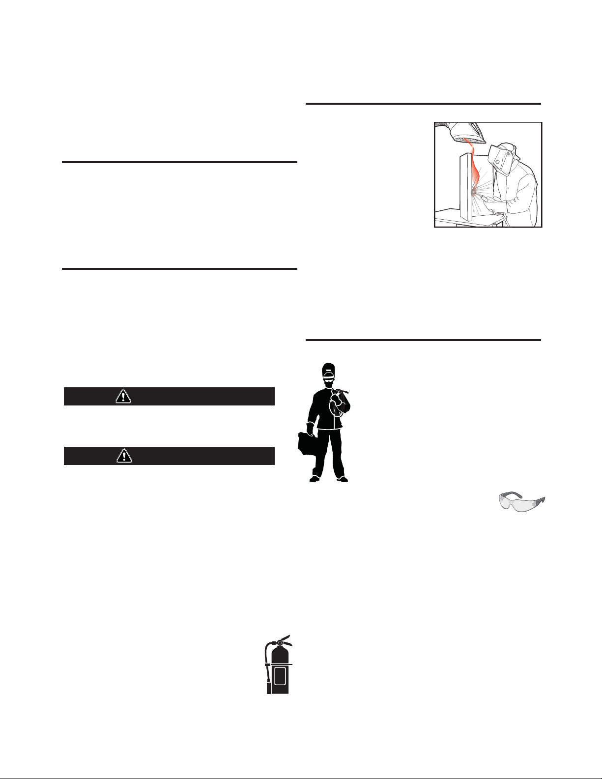
KEEP YOUR HEAD OUT OF THE FUMES.
DON’T get too close to the arc. Use
corrective lenses if necessary to
stay a reasonable distance away
from the arc.
READ and obey the Material Safety
Data Sheet (MSDS) and the warning
label that appears on all containers
of welding materials.
USE ENOUGH VENTILATION or
exhaust at the arc, or both, to keep
the fumes and gases from your breathing zone and the general area.
IN A LARGE ROOM OR OUTDOORS, natural ventilation may be
adequate if you keep your head out of the fumes (See below).
USE NATURAL DRAFTS or fans to keep the fumes away from your
face.
If you de velop unusual symptoms, see your supervisor. Perhaps the
welding atmosphere and ventilation system should be checked.
WEAR CORRECT EYE, EAR & BODY PROTECTION
PROTECT your eyes and face with welding helmet
properly fitted and with proper grade of filter plate
(See ANSI Z49.1).
PROTECT your body from welding spatter and arc
flash with protective clothing including woolen
clothing, flame-proof apron and gloves, leather
leggings, and high boots.
PROTECT others from splatter, flash, and glare with
protective screens or barriers.
IN SOME AREAS, protection from noise may be
appropriate.
BE SURE protective equipment is in good condition.
Also, wear safety glasses in work area AT ALL
TIMES.
SPECIAL SITUATIONS
DO NOT WELD OR CUT containers or materials which previously had
been in contact with hazardous substances unless they are properly
cleaned. This is extremely dangerous.
DO NOT WELD OR CUT painted or plated parts unless special
precautions with ventilation have been taken. They can release highly
toxic fumes or gases.
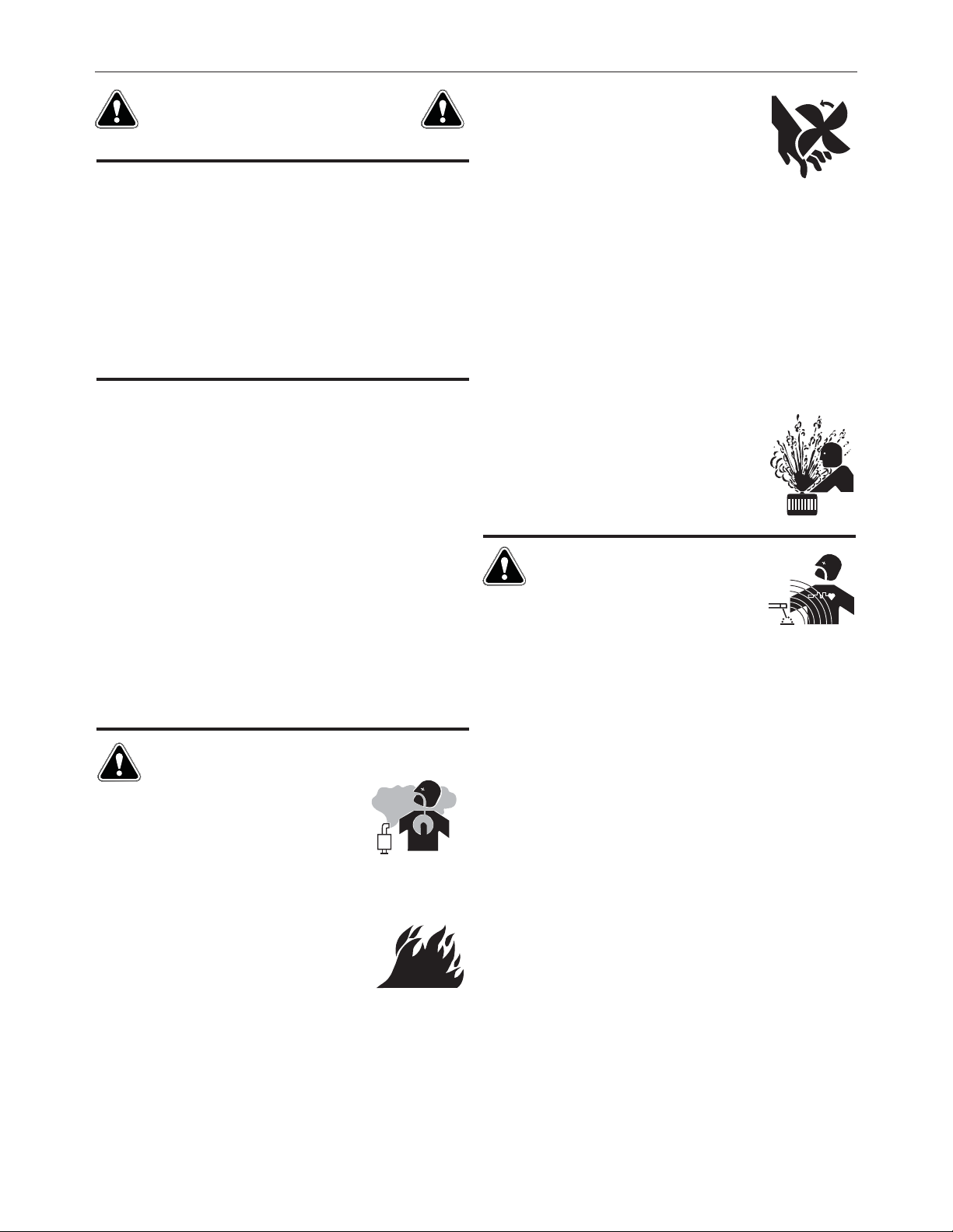
Additional precautionary measures
PROTECT compressed gas cylinders from excessive heat, mechanical
shocks, and arcs; fasten cylinders so they cannot fall.
BE SURE cylinders are never grounded or part of an electrical circuit.
REMOVE all potential fire hazards from welding area.
ALWAYS HAVE FIRE FIGHTING EQUIPMENT READY FOR
IMMEDIATE USE AND KNOW HOW TO USE IT.
Page 3
SECTION A:
WARNINGS
CALIFORNIA PROPOSITION 65 WARNINGS
Diesel Engines
Diesel engine exhaust and some of its constituents are known
to the State of California to cause cancer, birth defects, and other
reproductive harm.
Gasoline Engines
The engine exhaust from this product contains chemicals known
to the State of California to cause cancer, birth defects, or other
reproductive harm.
ARC WELDING CAN BE HAZARDOUS. PROTECT
YOURSELF AND OTHERS FROM POSSIBLE SERIOUS
INJURY OR DEATH. KEEP CHILDREN AWAY. PACEMAKER WEARERS SHOULD CONSULT WITH THEIR
DOCTOR BEFORE OPERATING.
Read and understand the following safety highlights. For additional
safety information, it is strongly recommended that you purchase a
copy of “Safety in Welding & Cutting - ANSI Standard Z49.1” from the
American Welding Society, P.O. Box 351040, Miami, Florida 33135 or
CSA Standard W117.2-1974. A Free copy of “Arc Welding Safety”
booklet E205 is available from the Lincoln Electric Company, 22801
St. Clair Avenue, Cleveland, Ohio 44117-1199.
BE SURE THAT ALL INSTALLATION, OPERATION,
MAINTENANCE AND REPAIR PROCEDURES ARE
PERFORMED ONLY BY QUALIFIED INDIVIDUALS.
SAFETY
1.d. Keep all equipment safety guards, covers and
devices in position and in good repair.Keep
hands, hair, clothing and tools away from
V-belts, gears, fans and all other moving parts
when starting, operating or repairing
equipment.
1.e. In some cases it may be necessary to remove safety guards to
perform required maintenance. Remove guards only when
necessary and replace them when the maintenance requiring
their removal is complete. Always use the greatest care when
working near moving parts.
1.f. Do not put your hands near the engine fan. Do not attempt to
override the governor or idler by pushing on the throttle control
rods while the engine is running.
1.g. To prevent accidentally starting gasoline engines while turning
the engine or welding generator during maintenance work,
disconnect the spark plug wires, distributor cap or magneto wire
as appropriate.
1.h. To avoid scalding, do not remove the radiator
pressure cap when the engine is
hot.
ELECTRIC AND
MAGNETIC FIELDS MAY
BE DANGEROUS
2.a. Electric current flowing through any conductor
causes localized Electric and Magnetic Fields (EMF). Welding
current creates EMF fields around welding cables and welding
machines
FOR ENGINE POWERED
EQUIPMENT.
1.a. Turn the engine off before troubleshooting
and maintenance work unless the
maintenance work requires it to be running.
1.b. Operate engines in open, well-ventilated
areas or vent the engine exhaust fumes outdoors.
1.c. Do not add the fuel near an open flame
welding arc or when the engine is running.
Stop the engine and allow it to cool before
refueling to prevent spilled fuel from
vaporizing on contact with hot engine parts
and igniting. Do not spill fuel when filling
tank. If fuel is spilled, wipe it up and do not start engine until
fumes have been eliminated.
2.b. EMF fields may interfere with some pacemakers, and welders
having a pacemaker should consult their physician before
welding.
2.c. Exposure to EMF fields in welding may have other health effects
which are now not known.
2.d. All welders should use the following procedures in order to
minimize exposure to EMF fields from the welding circuit:
2.d.1. Route the electrode and work cables together - Secure
them with tape when possible.
2.d.2. Never coil the electrode lead around your body.
2.d.3. Do not place your body between the electrode and work
cables. If the electrode cable is on your right side, the
work cable should also be on your right side.
2.d.4. Connect the work cable to the workpiece as close as possible to the area being welded.
2.d.5. Do not work next to welding power source.
3
Page 4
SAFETY
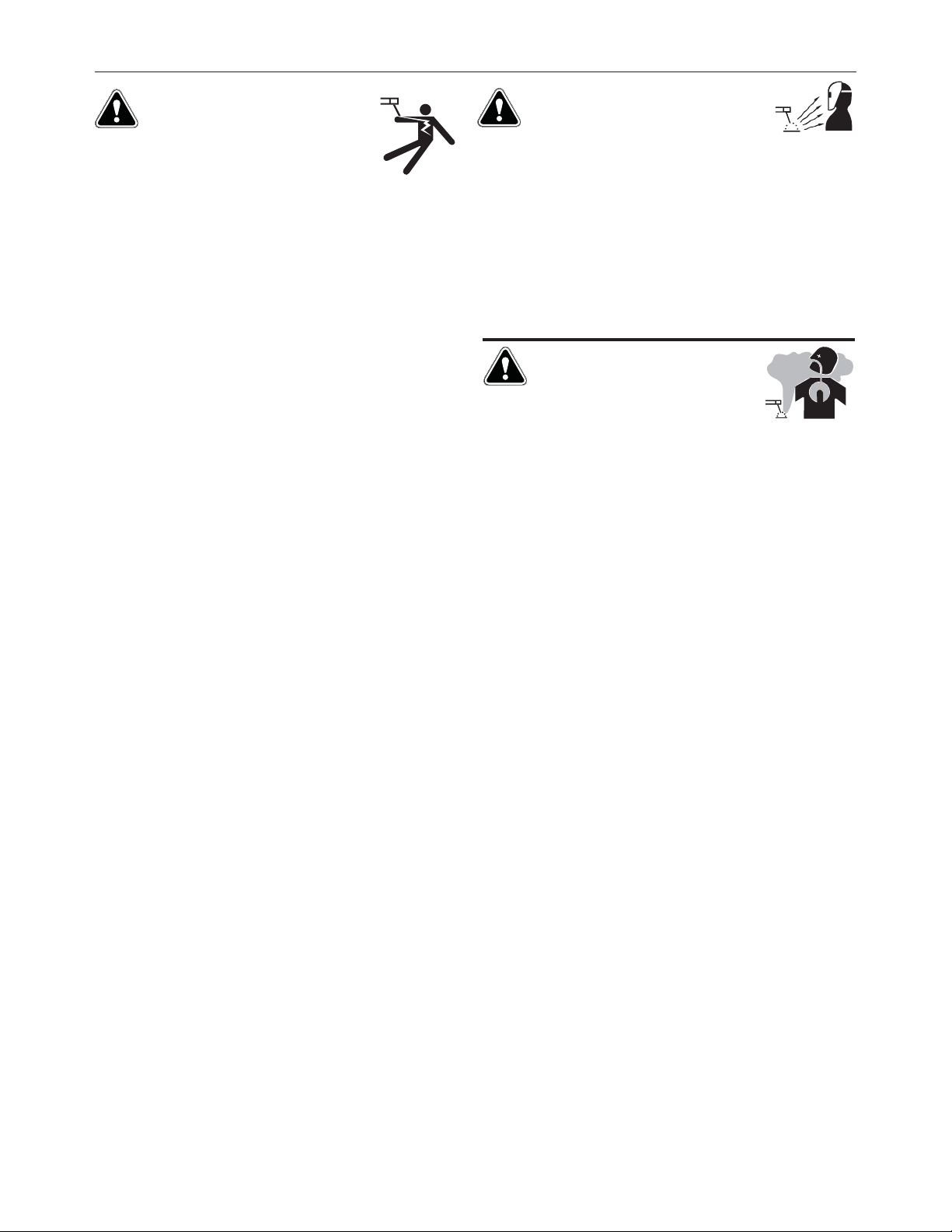
ELECTRIC SHOCK
CAN KILL.
3.a. The electrode and work (or ground) circuits are
electrically “hot” when the welder is on. Do
not touch these “hot” parts with your bare skin
or wet clothing. Wear dry, hole-free gloves to insulate hands.
3.b. Insulate yourself from work and ground using dry insulation.
Make certain the insulation is large enough to cover your full area
of physical contact with work and ground.
In addition to the normal safety precautions, if
welding must be performed under electrically
hazardous conditions (in damp locations or while
wearing wet clothing; on metal structures such as
floors, gratings or scaffolds; when in cramped
positions such as sitting, kneeling or lying, if there
is a high risk of unavoidable or accidental contact
with the workpiece or ground) use the following
equipment:
• Semiautomatic DC Constant Voltage (Wire) Welder.
• DC Manual (Stick) Welder.
• AC Welder with Reduced Voltage Control.
3.c. In semiautomatic or automatic wire welding, the electrode,
electrode reel, welding head, nozzle or semiautomatic welding
gun are also electrically “hot”.
3.d. Always be sure the work cable makes a good electrical
connection with the metal being welded. The connection should
be as close as possible to the area being welded.
3.e. Ground the work or metal to be welded to a good electrical (earth)
ground.
3.f. Maintain the electrode holder, work clamp, welding cable and
welding machine in good, safe operating condition. Replace
damaged insulation.
3.g. Never dip the electrode in water for cooling.
3.h. Never simultaneously touch electrically “hot” parts of electrode
holders connected to two welders because voltage
two can be the total of the open circuit voltage of both
welders.
3.i. When working above floor level, use a safety belt to protect
yourself from a fall should you get a shock.
between the
ARC RAYS CAN BURN.
4.a. Use a shield with the proper filter and cover plates to protect your
eyes from sparks and the rays of the arc when welding or
observing open arc welding. Headshield and filter lens should
conform to ANSI Z87. I standards.
4.b. Use suitable clothing made from durable flame-resistant material
to protect your skin and that of your helpers from the arc rays.
4.c. Protect other nearby personnel with suitable, non-flammable
screening and/or warn them not to watch the arc nor expose
themselves to the arc rays or to hot spatter or metal.
FUMES AND GASES
CAN BE DANGEROUS.
5.a. Welding may produce fumes and gases
hazardous to health. Avoid breathing these
fumes and gases. When welding, keep your head out of the fume.
Use enough ventilation and/or exhaust at the arc to keep fumes
and gases away from the breathing zone. When welding
with electrodes which require special ventilation
such as stainless or hard facing (see instructions
on container or MSDS) or on lead or cadmium
plated steel and other metals or coatings which
produce highly toxic fumes, keep exposure as low
as possible and within applicable OSHA PEL and
ACGIH TLV limits using local exhaust or
mechanical ventilation. In confined spaces or in
some circumstances, outdoors, a respirator may
be required. Additional precautions are also
required when welding on galvanized steel.
5. b. The operation of welding fume control equipment is affected by
various factors including proper use and positioning of the
equipment, maintenance of the equipment and the specific
welding procedure and application involved. Worker exposure
level should be checked upon installation and periodically
thereafter to be certain it is within applicable OSHA PEL and
ACGIH TLV limits.
5.c. Do not weld in locations near chlorinated hydrocarbon vapors
coming from degreasing, cleaning or spraying operations. The
heat and rays of the arc can react with solvent vapors to form
phosgene, a highly toxic gas, and other irritating products.
3.j. Also see It ems 6.c. and 8.
5.d. Shielding gases used for arc welding can displace air and
injury or death. Always use enough ventilation, especially in
confined areas, to insure breathing air is safe.
5.e. Read and understand the manufacturer’s instructions for this
equipment and the consumables to be used, including the
material safety data sheet (MSDS) and follow your employer’s
safety practices. MSDS forms are available from your welding
distributor or from the manufacturer.
5.f. Also see item 1.b.
4
cause
Page 5
SAFETY
WELDING AND CUTTING
SPARKS CAN CAUSE
FIRE OR EXPLOSION.
6.a. Remove fire hazards from the welding area. If
this is not possible, cover them to prevent the
welding sparks from starting a fire. Remember that welding
sparks and hot materials from welding can easily go through
small cracks and openings to adjacent areas. Avoid welding near
hydraulic lines. Have a fire extinguisher readily available.
6.b. Where compressed gases are to be used at the job site, special
precautions should be used to prevent hazardous situations.
Refer to “Safety in Welding and Cutting” (ANSI Standard Z49.1)
and the operating information for the equipment being used.
6.c. When not welding, make certain no part of the electrode circuit is
touching the work or ground. Accidental contact can cause
overheating and create a fire hazard.
6.d. Do not heat, cut or weld tanks, drums or containers until the
proper steps have been taken to insure that such procedures will
not cause flammable or toxic vapors from substances inside.
They can cause an explosion even though they have been
“cleaned”. For information, purchase “Recommended Safe
Practices for the Preparation for Welding and Cutting of
Containers and Piping That Have Held Hazardous Substances”,
AWS F4.1 from the American Welding Society (see address
above).
6.e. Vent hollow castings or containers before heating, cutting or
welding. They may explode.
6.f. Sparks and spatter are thrown from the welding arc. Wear oil free
protective garments such as leather gloves, heavy shirt, cuffless
trousers, high shoes and a cap over your hair. Wear ear plugs
when welding out of position or in confined places. Always wear
safety glasses with side shields when in a welding area.
6.g. Connect the work cable to the work as close to the welding area
as practical. Work cables connected to the building framework or
other locations away from the welding area increase the
possibility of the welding current passing through lifting chains,
crane cables or other alternate circuits. This can create fire
hazards or overheat lifting chains or cables until they fail.
6.h. Also see item 1.c.
CYLINDER MAY EXPLODE IF
DAMAGED.
7.a. Use only compressed gas cylinders containing
the correct shielding gas for the process used
and properly operating regulators designed for
the gas and pressure used. All hoses, fittings,
etc. should be suitable for the application and
maintained in good condition.
7.b. Always keep cylinders in an upright position securely chained to
an undercarriage or fixed support.
7.c. Cylinders should be located:
• Away from areas where they may be struck or subjected
to physical damage.
• A safe distance from arc welding or cutting operations
and any other source of heat, sparks, or flame.
7.d. Never allow the electrode, electrode holder or any other
electrically “hot” parts to touch a cylinder.
7.e. Keep your head and face away from the cylinder valve outlet
when opening the cylinder valve.
7.f. Valve protection caps should always be in place and hand tight
except when the cylinder is in use or connected for use.
7.g. Read and follow the instructions on compressed gas cylinders,
associated equipment, and CGA publication P-l, “Precautions for
Safe Handling of Compressed Gases in
Cylinders,” available
from the Compressed Gas Association 1235 Jefferson Davis
Highway, Arlington, VA 22202.
FOR ELECTRICALLY
POWERED EQUIPMENT.
8.a. Turn off input power using the disconnect
switch at the fuse box before working on the
equipment.
8.b. Install equipment in accordance with the U.S. National Electrical
Code, all local codes and the manufacturer’s recommendations.
6.I. Read and follow NFPA 51B “ Standard for Fire Prevention During
Welding, Cutting and Other Hot Work”, available from NFPA, 1
Batterymarch Park, PO box 9101, Quincy, Ma 022690-9101.
6.j. Do not use a welding power source for pipe thawing.
8.c. Ground the equipment in accordance with the U.S. National
Electrical Code and the manufacturer’s recommendations.
Refer to
http://www.lincolnelectric.com/safety
for additional safety information.
Welding Safety
Interactive Web Guide
for mobile devices
5
Page 6

Thank You
vv
for selecting a QUALITY product by Lincoln Electric. We want you
to take pride in operating this Lincoln Electric Company product
••• as much pride as we have in bringing this product to you!
The business of The Lincoln Electric Company is manufacturing and selling high quality welding equipment, consumables, and cutting equipment. Our challenge is to meet the needs of our customers and to exceed their expectations. On occasion, purchasers may ask Lincoln
Electric for advice or information about their use of our products. We respond to our customers based on the best information in our possession at that time. Lincoln Electric is not in a position to warrant or guarantee such advice, and assumes no liability, with respect to such information or advice. We expressly disclaim any warranty of any kind, including any warranty of fitness for any customerʼs particular purpose,
with respect to such information or advice. As a matter of practical consideration, we also cannot assume any responsibility for updating or
correcting any such information or advice once it has been given, nor does the provision of information or advice create, expand or alter any
warranty with respect to the sale of our products.
Lincoln Electric is a responsive manufacturer, but the selection and use of specific products sold by Lincoln Electric is solely within the control
of, and remains the sole responsibility of the customer. Many variables beyond the control of Lincoln Electric affect the results obtained in
applying these types of fabrication methods and service requirements.
Subject to Change – This information is accurate to the best of our knowledge at the time of printing. Please refer to www.lincolnelectric.com
for any updated information.
CUSTOMER ASSISTANCE POLICY
Please Examine Carton and Equipment For Damage Immediately
When this equipment is shipped, title passes to the purchaser upon receipt by the carrier. Consequently, Claims
for material damaged in shipment must be made by the purchaser against the transportation company at the
time the shipment is received.
Please record your equipment identification information below for future reference. This information can be
found on your machine nameplate.
Product _________________________________________________________________________________
Model Number ___________________________________________________________________________
Code Number or Date Code_________________________________________________________________
Serial Number____________________________________________________________________________
Date Purchased___________________________________________________________________________
Where Purchased_________________________________________________________________________
Whenever you request replacement parts or information on this equipment, always supply the information you
have recorded above. The code number is especially important when identifying the correct replacement parts.
On-Line Product Registration
- Register your machine with Lincoln Electric either via fax or over the Internet.
• For faxing: Complete the form on the back of the warranty statement included in the literature packet
accompanying this machine and fax the form per the instructions printed on it.
• For On-Line Registration: Go to our
Your Product”. Please complete the form and submit your registration.
Read this Operators Manual completely before attempting to use this equipment. Save this manual and keep it
handy for quick reference. Pay particular attention to the safety instructions we have provided for your protection.
The level of seriousness to be applied to each is explained below:
WEB SITE at www.lincolnelectric.com. Choose “Support” and then “Register
WARNING
This statement appears where the information must be followed exactly to avoid serious personal injury or loss of life.
CAUTION
This statement appears where the information must be followed to avoid minor personal injury or damage to this equipment.
Page 7

TABLE OF CONTENTS
Page
Installation.......................................................................................................................Section A
Technical Specifications ...............................................................................................A-1, A-2
Safety Precautions ...............................................................................................................A-3
Suitable Location, Lifting ...............................................................................................A-3
Stacking ........................................................................................................................A-3
Tilting.............................................................................................................................A-3
Input and Ground Connections .....................................................................................A-3
Machine Grounding.......................................................................................................A-3
Input Connection ..................................................................................................................A-4
Input Fuse and Supply Wire..........................................................................................A-4
Input Voltage Selection .................................................................................................A-4
Reconnect Diagram..............................................................................................................A-5
High Frequency Protection............................................................................................A-5
System Overview and Connection Diagram.........................................................................A-5
Connection Diagram......................................................................................A-6 thru A-13
Recommended Work Cable Sizes ..............................................................................A-14
Output Cable Guidelines .............................................................................................A-15
Cable Inductance and its Effects on Welding..............................................................A-16
Remote Sense Lead Specifications ............................................................................A-16
Voltage Sensing Considerations for Multiple Arc Systems .........................................A-17
Circumferential Applications........................................................................................A-18
Control Cable Connections ................................................................................................A-19
________________________________________________________________________________
Operation.........................................................................................................................Section B
Safety Precautions ...............................................................................................................B-1
Power-Up Sequence .....................................................................................................B-1
Duty Cycle.....................................................................................................................B-1
Graphic Symbols ...................................................................................................B-1, B-2
Product Description ..............................................................................................................B-3
Recommended Processes and Equipment, Equipment Limitations.....................................B-3
Basic Package
Robotic Feeder Control Cables and Adapters......................................................................B-4
Design Features ...................................................................................................................B-5
Case Front Controls .............................................................................................................B-5
Case Back Controls..............................................................................................................B-6
Common Welding Procedures................................................................................B-7 thru B-9
________________________________________________________________________________
, Sync Tandem Package, Common Optional Kits ........................................B-4
vivi
Accessories .....................................................................................................Section C
Kits, Options / Accessories....................................................................................C-1
Field Installed Options...........................................................................................C-1
Power Wave Accessory Connection Scheme .......................................................C-1
________________________________________________________________________
Maintenance ....................................................................................................Section D
Safety Precautions ...............................................................................................................D-1
Visual Inspection ..................................................................................................................D-1
Routine Maintenance ...........................................................................................................D-1
Periodic Maintenance...........................................................................................................D-1
Calibration Specification.......................................................................................................D-1
________________________________________________________________________________
Troubleshooting ..............................................................................................Section E
Safety Precautions.................................................................................................E-1
How to Use Troubleshooting Guide.......................................................................E-1
Using Status LED, Error Fault Codes and Input Control Board....................................E-2, E-3
Troubleshooting Guide...................................................................................E-4, E-5
________________________________________________________________________________
Wiring Diagram and Dimension Print ............................................................Section F
________________________________________________________________________
Parts Pages ...............................................................................................................P-721 Series
_______________________________________________________________________
________
Page 8
A-1
INSTALLATION
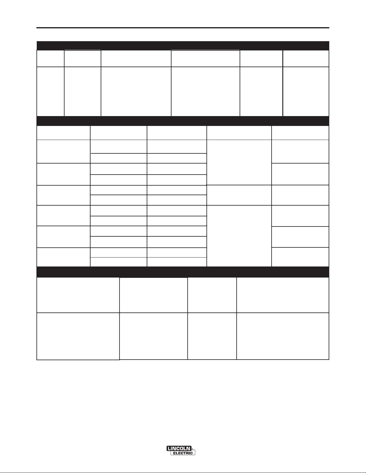
TECHNICAL SPECIFICATIONS - POWER WAVE®S700
POWER SOURCE-INPUT VOLTAGE AND CURRENT
Model
K3279-1
Process
Duty Cycle
100% rating
Input Voltage ± 10%
380-415/440-460/500/575
RATED OUTPUT
Duty Cycle
Amperes
Input Amperes
55/46/42/38
Volts at Rated
Amperes
Idle Power
(Watts)
205W Fan Off
(Max.)
360W Fan On
(Max.)
A-1
Power Factor @
Rated Output
.95
OCV
(U0)
GMAW
GMAW-P
GTAW
SMAW
FCAW-GS
FCAW-SS
RECOMMENDED INPUT WIRE AND FUSE SIZES
INPUT
VOLTAGE / 3 PHASE/
FREQUENCY
380/3/50
460/3/60
500/3/60
575/3/60
60%
100%
60%
100%
60%
100%
60%
100%
60%
100%
60%
100%
Maximum
Input Amperes
75
62
57
50
900A
700A
900A
700A
900A
700A
900A
700A
900A
700A
900A
700A
Type 75C
Copper Wire in
Conduit AWG
(IEC) Sizes 40C
(104°F) Ambient
6 (16)
6 (16)
8 (10)
8 (10)
44V
34V
44V
70V AVG.
78V PEAK
70V AVG.
78V PEAK
24V AVG.
27V PEAK
60V AVG.
67V PEAK
70V AVG.
78V PEAK
70V AVG.
78V PEAK
1
TIME DELAY FUSE
OR BREAKER
AMPERAGE
90
80
70
60
2
1. Based on U.S. National electrical Code
2. Also called " inverse time" or "thermal / magnetic" circuit breakers; circuit breakers that have a delay in trip-
ping action that decreases as the magnitude of the current increases.
POWER WAVE®S700
Page 9

A-2
MODEL
CONFORMITY MARK
INSTALLATION
PHYSICAL DIMENSIONS
HEIGHT
WIDTH
DEPTH
A-2
WEIGHT
K3279-1
EN 60974-1
*
CSA C/US
30.10 in (76.5 cm)
19.1 in (48.5 cm)
36.7 in (93.2 cm)
TEMPERATURE RANGES
OPERATING TEMPERATURE RANGE
Environmentally Hardened: -4°F to 104°F (-20C to 40C)
IP23 155º(F) Insulation Class
Environmentally Hardened: -40°F to 185°F (-40C to 85C)
STORAGE TEMPERATURE RANGE
* An External filter will be required to meet CE or C-TICK conducted emission requirements.
Order K2444-4 filter kit to meet these requirements.
400 lbs (181 kg)
Thermal tests have been performed at ambient temperature. The duty cycle (duty factor) at 40°C has
been determined by simulation.
POWER WAVE®S700
Page 10
A-3
INSTALLATION
SAFETY PRECAUTIONS Read this
entire installation section before you start installa-
tion.
WARNING
ELECTRIC SHOCK can kill.
• Only qualified personnel should
perform this installation.
• Turn the input power OFF at the
disconnect switch or fuse box before working on
this equipment. Turn off the input power to any
other equipment connected to the welding system
at the disconnect switch or fuse box before working on the equipment.
• Do not touch electrically hot parts.
• Always connect the Power Wave
ing lug (located inside the reconnect input
access door) to a proper safety (Earth) ground.
-------------------------------------------------------------
®
S700 ground-
SUITABLE LOCATION
Location and ventilation for cooling
Place the welder where clean cooling air can freely
circulate in through the rear louvers and out through
the case sides and front. Dirt, dust, or any foreign
material that can be drawn into the welder should be
kept at a minimum. The use of air filters on the air
intake is not recommended because normal air flow
may be restricted. Failure to observe these precautions can result in excessive operating temperatures
and nuisance shutdowns.
• Place the welder where clean cooling air can freely
circulate in through the rear louvers and out
through the case sides and front.
A-3
Environmental limitations
The Power Wave
outdoor environment. The Power Wave
not be subjected to falling water during use nor
should any parts of it be submerged in water. Doing
so may cause improper operation as well as pose a
safety hazard. The best practice is to keep the
machine in a dry, sheltered area.
• Do not mount the Power Wave
bustible surfaces. Where there is a combustible
surface directly under stationary or fixed electrical
equipment, that surface shall be covered with a
steel plate at least .060” (1.6mm) thick, which shall
extend not less than 5.90” (150mm) beyond the
equipment on all sides.
®
S700 is IP23 rated for use in an
®
S700 should
®
S700 over com-
LIFTING
WARNING
• Lift only with equipment of adequate lifting capacity.
• Be sure machine is stable when
lifting.
• Do not operate machine while
suspended when lifting.
FALLING
EQUIPMENT can
cause injury.
-------------------------------------------------------------
Lift the machine by the lift bail only. The lift bail is
designed to lift the power source only. Do not
attempt to lift the Power Wave
sories attached to it.
®
S700 with acces-
STACKING
The Power Wave®S700 cannot be stacked.
• Dirt, dust, or any foreign material that can be drawn
into the welder should be kept at a minimum. The
use of air filters on the air intake is not recommended because normal air flow may be restricted.
Failure to observe these precautions can result in
excessive operating temperatures and nuisance
shutdowns.
• The best practice is to keep the machine in a dry,
sheltered area.
POWER WAVE®S700
INPUT AND GROUND CONNECTIONS
Only a qualified electrician should connect the Power
®
Wave
dance with the appropriate National Electrical Code,
all local codes and the information in this manual.
S700. Installation should be made in accor-
MACHINE GROUNDING
The frame of the welder must be grounded. A ground
terminal marked with the symbol shown is located
inside the reconnect/input access door for this purpose.
See your local and national electrical codes for proper grounding methods.
Page 11
A-4
INPUT CONNECTION
WARNING
INSTALLATION
INPUT FUSE AND SUPPLY WIRE
CONSIDERATIONS
A-4
ELECTRIC SHOCK can kill.
Only a qualified electrician should
connect the input leads to the
Power Wave
®
S700. Connections
should be made in accordance with all local and
national electrical codes and the connection diagrams located on the inside of the
reconnect/input access door of the machine.
Failure to do so may result in bodily injury or
death.
------------------------------------------------------------------------
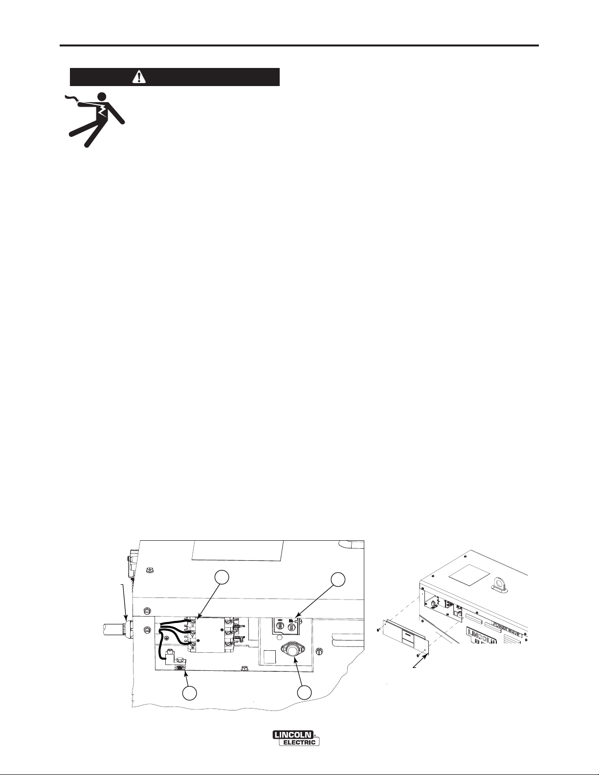
(See Figure A.1)
Use a three-phrase supply line. A 1.75 inch diameter
access hole with strain relief is located on the case
back. Route input power cable through this hole and
connect L1, L2, L3 and ground per connection diagrams and National Electric Code. To access the
input power connection block, remove two screws
holding the access door to the side of the machine.
ALWAYS CONNECT THE POWER WAVE GROUND-
ING LUG (LOCATED AS SHOWN IN FIGURE A.1)
TO A PROPER SAFETY (EARTH) GROUND.
Refer to Specification Section for recommended fuse,
wire sizes and type of the copper wires. Fuse the
input circuit with the recommended super lag fuse or
delay type breakers (also called "inverse time" or
"thermal/magnetic" circuit breakers). Choose input
and grounding wire size according to local or national
electrical codes. Using input wire sizes, fuses or circuit breakers smaller than recommended may result in
"nuisance" shut-offs from welder inrush currents, even
if the machine is not being used at high currents.
INPUT VOLTAGE SELECTION
Welders are shipped connected for the highest input
voltage listed on the rating plate. To move this connection to a different input voltage, see the diagram
located on the inside of the input access door, also
illustrated below. If the Auxiliary lead (indicated as ʻAʼ)
is placed in the wrong position, there are two possible
results. If the lead is placed in a position higher than
the applied line voltage, the welder may not come on
at all. If the Auxiliary lead is placed in a position lower
than the applied line voltage, the welder will not come
on, and the two circuit breakers in the reconnect area
will open. If this occurs, turn off the input voltage,
properly connect the auxiliary lead, reset the breakers,
and try again
Input Power Compartment Controls Description:
1
. Input Contactor: Connects 3-phase power to the
welder.
2. Ground Lug: Provides an “Earth Ground” connec-
tion to the welder frame.
3. Auxiliary Reconnect: Allows for easy tap selection
on the auxiliary transformers over the range of input
voltages.
4. Fuse: Protects the auxiliary transformers.
FIGURE A.1
POWER CONNECTION BLOCK
1
INPUT CORD STRAIN RELIEF
ROUTE INPUT CORD
THROUGH RELIEF AND
TWIST NUT TO TIGHTEN
CONNECT EACH PHASE OF A THREE-PHASE
CONDUCTOR HERE
3
INPUT POWER
ACCESS DOOR
GROUND CONNECTION
2
CONNECT GROUND LEAD PER LOCAL
AND NATIONAL ELECTRIC CODE
4
POWER WAVE®S700
Page 12

A-5
RECONNECT DIAGRAM
INSTALLATION
A-5
INPUT SUPPLY CONNECTION DIAGRAM
WARNING
ELECTRIC
SHOCK
CAN KILL
VOLTAGE=380-415V
380-415V
440-460V
500V
550-575V
Do not operate with covers removed
Disconnect input power before servicing
Do not touch electrically live parts
Only qualified persons should install,
use or service this equipment
VOLTAGE=440-460V
380-415V 380-415V 380-415V
'A'
440-460V
500V
550-575V
'A'
HIGH FREQUENCY PROTECTION
Locate the Power Wave®S700 away from radio controlled machinery. The normal operation of the Power
®
Wave
S700 may adversely affect the operation of RF
controlled equipment, which may result in bodily injury
or damage to the equipment.
SYSTEM OVERVIEW AND CONNECTION
DIAGRAM
W / L3
V / L2
U / L1
VOLTAGE=500V
440-460V
500V
550-575V
CR1
VOLTAGE=550-575V
440-460V
'A'
500V
550-575V
'A'
S26047
C
THE LINCOLN ELECTRIC CO. CLEVELAND, OHIO U.S.A.
GTAW (TIG) Welding
A user interface is required for adjusting the TIG welding settings. A Power Feed series wire feeder may
also be used as a user interface. Refer to the connection diagrams for more connection information.
SMAW (Stick) Welding
A user interface is required for adjusting the stick
welding settings. A Power Feed series wire feeder
may also be used as a user interface. Refer to the
connection diagrams for more connection information.
GMAW (MIG) Welding
An ArcLink compatible wire feeder is required for MIG
welding.
POWER WAVE®S700
Page 13
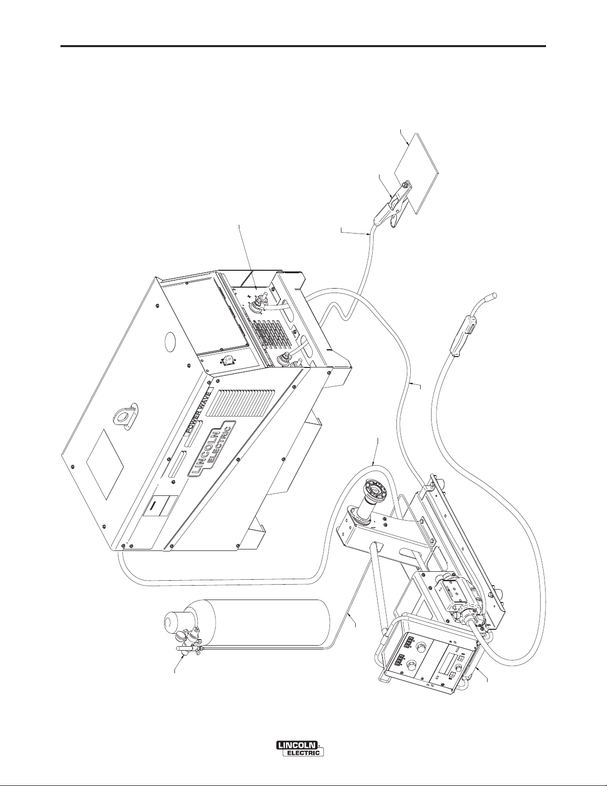
A-6
REGULATOR
FLOWMETER
G
AS
HOSE
WORK
PIECE
WORK
CLAMP
TO
POSITI
VE
(+)
STUD
TO
NEGATIVE
(-)
STUD
PF10-M
WIRE
F
EEDER
A
RCLINK
C
ABLE
K
15
43-[XX]
FR
ONT
DOOR
H
AS
BEEN
REMO
VED
TO
SHOWN
C
ABLE
CONNECTIONS
INSTALLATION
A-6
MIG PROCESS
FIGURE A.2
P
VE
R
C
BE
AS
H
AB
C
D
S
O
S
(-
N
C
POWER WAVE®S700
AB
C
43
RC
15
H
AS
S
(
VE
P
EE
F
Page 14
A-7
INSTALLATION
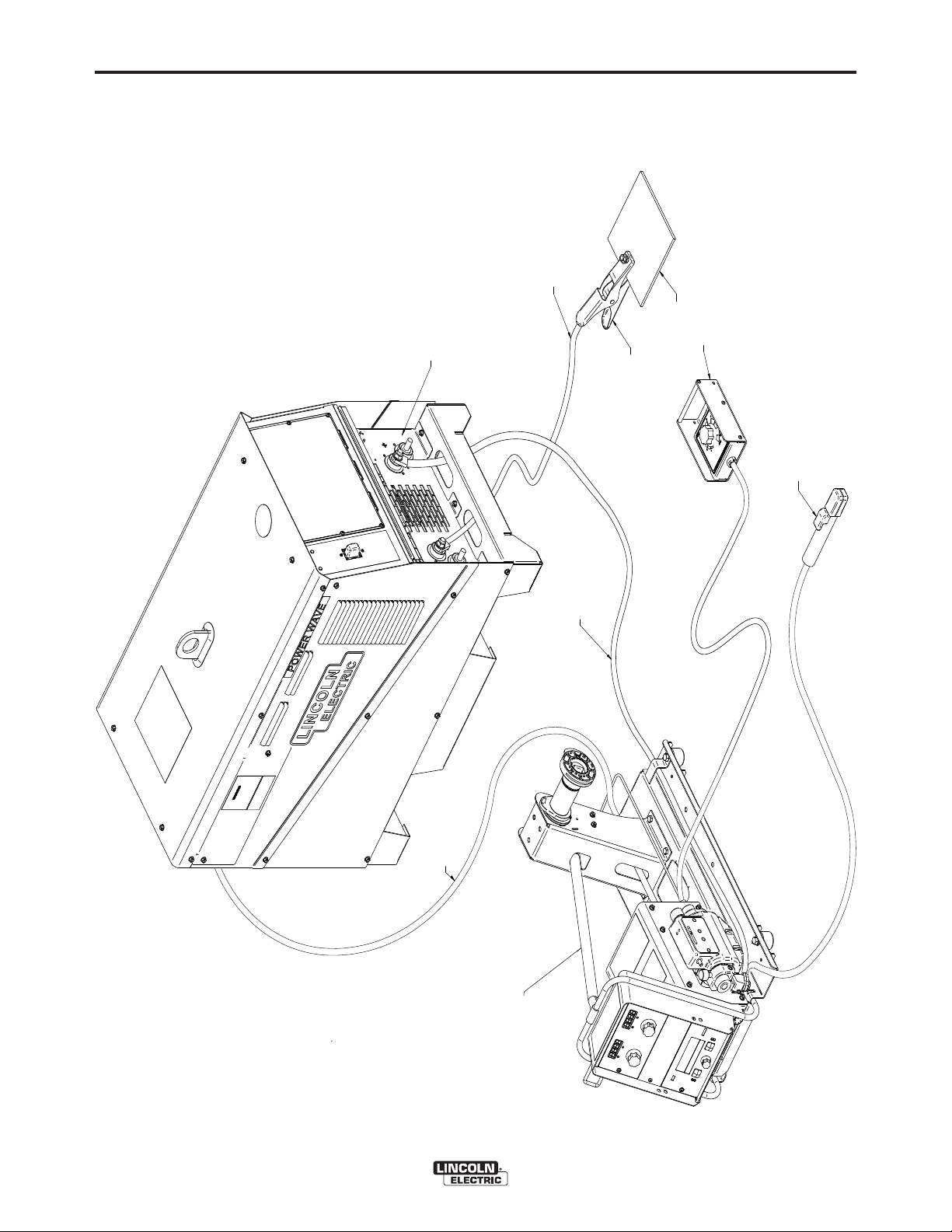
STICK PROCESS
FIGURE A.3
TO NEGATIVE (-) STUD
FRONT DOOR HAS BEEN REMOVED
TO SHOWN CABLE CONNECTIONS.
A-7
K857
(OPTIONAL WITH K2320-1
REQUIRED FOR COMPATIBILITY)
REMOTE CONTROL BOX
WORK PIECE
WORK CLAMP
ELECTRODE HOLDER KIT
K2394-1 KIT
(INCLUDES GROUND CLAMP)
ARCLINK CABLE
TO POSITIVE (+) STUD
(K1543-XX)
PF10M WITH K2320-1
CONNECTION KIT
POWER WAVE®S700
(OPTIONAL)
Page 15

A-8
INSTALLATION
TIG PROCESS
FIGURE A.4
FRONT DOOR HAS BEEN REMOVED
POWERWAVE S700
TO SHOWN CABLE CONNECTION S.
A-8
WORK PIECE
WORK CLAMP
TO POSITIVE (+) STUD
K870 FOOT AMPRTOL
TO NEGATIVE (-) STUD
TWO PIECE TIG TORCH
ARCLINK CABLE
K1543-(XX)
GAS HOSE
REGULATOR
FLOWMETER
WITH GAS VALVE.
POWER WAVE®S700
PF10-M WITH K2320-1 FOOT
AMPTROL CONNECTION KIT
Page 16

A-9
INSTALLATION
MIG AND WATER COOLER PROCESS
FIGURE A.5
WORK PIECE
WORK CLAMP
A-9
FRONT DOOR HAS BEEN REMOVED
TO SHOWN CABLE CONNECTIONS
TO NEGATIVE (-) STUD
ARCLINK CABLE
K1543-[XX]
TO POSITIVE (+) STUD
MAGNUM WATER
COOLED GUN ASSEMBLY
GAS HOSE
REGULATOR
FLOWMETER
PF 10M
WIRE FEEDER
K1859-X
WATER HOSE KIT
COOL ARC 55
WATER COOLER
K590-X WATER
CONNECTION KIT
POWER WAVE®S700
Page 17

A-10
INSTALLATION
SYNCHRONIZED TANDEM CONNECTION
FIGURE A.6
K3171-1 AUTODRIVE 19
TANDEM
WIRE DRIVE
CONTROL CABLE
(K1785-XX OR K2709-XX)
(K1543-XX)
ARCLINK CABLE
A-10
K3171-1 AUTODRIVE 19
TANDEM
POWER WAVE
S700
POWER WAVE
S700
WIRE DRIVE
CONTROL CABLE
M20979-1 SYNC
TANDEM CABLE
(K1785-XX OF K2709-XX)
(K1543-XX)
ARCLINK CABLE
POWER WAVE®S700
Page 18

A-11
INSTALLATION
A-11
ROBOTIC SINGLE ARM PROCESS SETUP
FIGURE A.7
BACK OF POWER SOURCE
WORK SENSE
ETHERNET CONNECTION
LEAD CONNECTION
TO AUTODRIVE 19
ARCLINK CONNECTION
POWERWAVE S700
to show cable connections.
Front door has been removed
WORK CABLE(-)
K2163-XX or K1842-XX
AUTODRIVE
ELECTRODE CABLE (+)
K2163-XX or K1842-XX
ETHERNET CONNECTION
K1543-XX
ARCLINK CABLE
K940-25 OR K1811-XX
OPTIONAL WORK
SENSE LEAD KIT
WORK PIECE
WIRE FEEDER
(K1785-XX OF K2709-XX)
WIRE DRIVE
CONTROL CABLE
AUTODRIVE 19
CONTROLLER
K3004-1
ARCLINK IN
ARCLINK OUT
WIRE FEEDER
POWER WAVE®S700
Page 19

A-12
INSTALLATION
ANALOG INTERFACE SETUP
FIGURE A.8
ANALOG INTERFACE
K1543-XXX
ARCLINK CONTROL
CABLE
A-12
WIRE DRIVE
K1785-XXX OR K2709-XX
AUTODRIVE 19
CONTROLLER
CONTROL CABLE
TO WIRE DRIVE
K1543-XXX
CABLE
ARCLINK CONTROL
POWER WAVE®S700
Page 20

J5
J2
J7
J1010A1
J4
J9
N
O
S1
N
O
S2
J15
J
10B1
J11
J8
N
O
S3
J3
BT1
LED7
LED8
J12
J13
DIGITAL CCONTNTROL
J6
G
4800
SERI
ES
CONTROL
BOARD
REMOVE
THE
S
CREWS
FROM
FRONT
PAN
EL
,
A
ND
FOLD
DOWN
TO
A
CCESS
CONTROL
PC
BOA
RD.
POWERW
AVE
S
700
DIP
SWITCH MACHINE
1 MACHINE
2
S1
ON
(DEFAULT)
OFF
S2
ON
(DEFAULT)
ON
(DEFAULT)
S3
ON
(DEFAULT)
ON
(DEFAULT)
A-13
INSTALLATION
A-13
CONTROL BOARD SETUP FOR SYNCHRONIZED TANDEM
FIGURE A.9
10
2
B
,
E
PA
F
F
CR
S
T
1
S
CC
A
T
D
F
ND
RD
B
P
C
J
C
ES
SE
48
70
S
AVE
J3
POWER WAVE®S700
Page 21

A-14
INSTALLATION
A-14
RECOMMENDED WORK CABLE
SIZES FOR ARC WELDING
Connect the electrode and work cables between the
®
appropriate output studs of the Power Wave
per the following guidelines:
• Most welding applications run with the electrode
being positive (+). For those applications, connect
the electrode cable between the wire drive feed plate
and the positive (+) output stud on the power source.
Connect a work lead from the negative (-) power
source output stud to the work piece
• When negative electrode polarity is required, such
as in some Innershield
output connections at the power source (electrode
cable to the negative (-) stud, and work cable to the
positive (+) stud).
®
applications, reverse the
S700
CAUTION
Negative electrode polarity operation WITHOUT
use of a remote work sense lead (21) requires the
Negative Electrode Polarity attribute to be set. See
the Remote Sense Lead Specification section of
this document for further details.
-----------------------------------------------------------------------
For additional Safety information regarding the electrode and work cable set-up, See the standard
“SAFETY INFORMATION” located in the front of this
Instruction Manual.
The following recommendations apply to all output polarities and weld modes:
• Select the appropriate size cables per the
“Output Cable Guidelines” below. Excessive volt-
age drops caused by undersized welding cables and
poor connections often result in unsatisfactory welding performance. Always use the largest welding
cables (electrode and work) that are practical, and
be sure all connections are clean and tight.
Note: Excessive heat in the weld circuit indicates
undersized cables and/or bad connections.
• Route all cables directly to the work and wire
feeder, avoid excessive lengths and do not coil
excess cable. Route the electrode and work cables
in close proximity to one another to minimize the
loop area and therefore the inductance of the weld
circuit.
• Always weld in a direction away from the work
(ground) connection.
Table A.1 shows copper cable sizes recommended for
different currents and duty cycles. Lengths stipulated
are the distance from the welder to work and back to
the welder again. Cable sizes are increased for
greater lengths primarily for the purpose of minimizing
cable drop.
POWER WAVE®S700
Page 22

A-15
INSTALLATION
OUTPUT CABLE GUIDELINES (Table A.1)
A-15
Amperes
200
200
250
250
250
250
300
300
350
400
400
Percent Duty
Cycle
60
100
30
40
60
100
60
100
40
60
100
CABLE SIZES FOR COMBINED LENGTHS OF ELECTRODE AND WORK
CABLES [RUBBER COVERED COPPER - RATED
0 to 50 Ft.
2
2
3
2
1
1
1
2/0
1/0
2/0
3/0
50 to 100 Ft.
2
2
3
2
1
1
1
2/0
1/0
2/0
3/0
100 to 150 Ft.
2
2
2
1
1
1
1
2/0
2/0
2/0
3/0
167°F (75°C)]**
150 to 200 Ft.
1
1
1
1
1
1
1/0
2/0
2/0
3/0
3/0
200 to 250 Ft.
1/0
1/0
1/0
1/0
1/0
1/0
2/0
3/0
3/0
4/0
4/0
500
600
600
600
650
650
700
800
800
900
900
** Tabled values are for operation at ambient temperatures of 104°F (40°C) and below. Applications above 104°F (40°C) may
require cables larger than recommended, or cables rated higher than 167°F (75°C).
60
60
80
100
60
80
100
80
100
80
100
2/0
3/0
2-1/0
2-1/0
3/0
2-1/0
2-2/0
3-1/0
2-3/0
2-4/0
3-3/0
2/0
3/0
2-1/0
2-1/0
3/0
2-1/0
2-2/0
3-1/0
2-3/0
2-4/0
3-3/0
3/0
3/0
2-1/0
2-1/0
4/0
2-1/0
2-3/0
3-1/0
2-3/0
2-4/0
3-3/0
3/0
4/0
2-2/0
2-2/0
2-2/0
2-2/0
2-3/0
2-3/0
2-3/0
2-4/0
3-3/0
4/0
2-3/0
2-3/0
2-3/0
2-3/0
2-3/0
2-4/0
2-4/0
2-4/0
4-2/0
3-3/0
POWER WAVE®S700
Page 23

A-16
INSTALLATION
CABLE INDUCTANCE AND ITS
EFFECTS ON WELDING
Excessive cable inductance will cause the welding
performance to degrade. There are several factors
that contribute to the overall inductance of the cabling
system including cable size, and loop area. The loop
area is defined by the separation distance between
the electrode and work cables, and the overall welding
loop length. The welding loop length is defined as the
total of length of the electrode cable (A) + work cable
(B) + work path (C) (See Figure A.10).
A-16
There are several different sense lead configurations
that can be used depending on the application. In
extremely sensitive applications it may be necessary
to route cables that contain the sense leads away
from the electrode and work welding cables.
CAUTION
If the auto sense lead feature is disabled and
remote voltage sensing is enabled but the sense
leads are missing or improperly connected
extremely high welding outputs may occur.
------------------------------------------------------------------------
Electrode Voltage Sensing
To minimize inductance always use the appropriate
size cables, and whenever possible, run the electrode
and work cables in close proximity to one another to
minimize the loop area. Since the most significant factor in cable inductance is the welding loop length,
avoid excessive lengths and do not coil excess cable.
For long work piece lengths, a sliding ground should
be considered to keep the total welding loop length as
short as possible.
REMOTE SENSE LEAD
SPECIFICATIONS
Voltage Sensing Overview
The best arc performance occurs when the Power
®
Wave
tions.
Depending upon the process, inductance within the
electrode and work cables can influence the voltage
apparent at the studs of the welder and can have a
dramatic negative effect on welding performance. To
counteract this negative effect, remote voltage sense
leads are used to improve the accuracy of the arc voltage information supplied to the control pc board.
Sense lead kits (K1811-XX) are available for this purpose.
S700 has accurate data about the arc condi-
The remote ELECTRODE sense lead (67) is built into
the wire feeder control cable and accessible at the
wire drive. It should always be connected to the wire
drive feed plate when a wire feeder is present.
Enabling or disabling electrode voltage sensing is
application specific, and automatically configured
through software.
B
FIGURE A.10
A
C
WORK
POWER WAVE®S700
Page 24

A-17
INSTALLATION
General Guidelines for Voltage Sense Leads
A-17
If Sense Leads ARE NOT Used:
Sense leads should be attached as close to the weld
as practical, and out of the weld current path when
possible. In extremely sensitive applications it may be
necessary to route cables that contain the sense
leads away from the electrode and work welding
cables.
Voltage sense leads requirements are based on the
weld process (See Table A.2)
• Avoid common current paths. Current from adjacent arcs can induce voltage into each others current paths that can be misinterpreted by the power
sources and result in arc interference.
If Sense Leads ARE Used:
• Position the sense leads out of the path of the weld
current. Especially any current paths common to
adjacent arcs. Current from adjacent arcs can
induce voltage into each others current paths that
VOLTAGE SENSING CONSIDERATIONS
FOR MULTIPLE ARC SYSTEMS
Special care must be taken when more than one arc
is welding simultaneously on a single part. Multiple arc
applications do not necessarily dictate the use of
remote work voltage sense leads, but they are strongly recommended.
can be misinterpreted by the power sources, and
result in arc interference.
• For longitudinal applications, connect all work leads
at one end of the weldment, and all of the work voltage sense leads at the opposite end of the weldment. Perform welding in the direction away from
the work leads and toward the sense leads.
(See Figure A.11)
TABLE A.2
Process
Electrode Voltage Sensing
67 lead
GMAW
GMAW-P
FCAW
GTAW
SMAW
(1)
The electrode voltage sense lead (67) is automatically enabled by the weld process, and integral to the 5 pin arclink control cable (K1543xx).
(2)
When a work voltage sense lead (21) is connected the power source will automatically switch over to using this feedback (if the auto
sense feature is enabled).
(3)
Negative polarity semi-automatic process operation WITHOUT use of a remote work sense lead (21) requires the Negative Electrode
Polarity attribute to be set.
67 lead required
67 lead required
67 lead required
Voltage sense at studs
Voltage sense at studs
FIGURE A.11
DIRECTION
OF TRAVEL
(1)
Work Voltage Sensing
21 lead
21 lead optional
21 lead optional
21 lead optional
Voltage sense at studs
Voltage sense at studs
CONNECT ALL SENSE
LEADS AT THE END
OF THE WELD.
(2)
(3)
(3)
(3)
CONNECT ALL
WORK LEADS AT
THE BEGINNING
OF THE WELD.
POWER WAVE®S700
Page 25

A-18
INSTALLATION
• For circumferential applications, connect all work
leads on one side of the weld joint, and all of the
work voltage sense leads on the opposite side,
such that they are out of the current path.
(See Figure A.12)
FIGURE A.12
POWER
SOURCE
#1
WER
PO
SOURCE
#2
A-18
POWER
SOURCE
#1
WER
PO
SOURCE
#1
POWER
SOURCE
#2
WER
PO
SOURCE
#2
POWER WAVE®S700
Page 26

A-19
INSTALLATION
A-19
CONTROL CABLE CONNECTIONS
GENERAL GUIDELINES
Genuine Lincoln control cables should be used at all
times (except where noted otherwise). Lincoln cables
are specifically designed for the communication and
®
power needs of the Power Wave
tems. Most are designed to be connected end-to-end
for ease of extension. Generally, it is recommended
that the total length not exceed 100ft. (30.5m). The
use of non-standard cables, especially in lengths
greater than 25 feet, can lead to communication problems (system shutdowns), poor motor acceleration
(poor arc starting) and low wire driving force (wire
feeding problems). Always use the shortest length of
control cable possible and DO NOT coil excess
cable.
Regarding cable placement, best results will be
obtained when control cables are routed separate
from the weld cables. This minimizes the possibility of
interference between the high currents flowing
through the weld cables and the low level signals in
the control cables. These recommendations apply to
all communication cables including ArcLink
Ethernet connections.
COMMON EQUIPMENT CONNECTIONS
Connection Between Power Source and ArcLink
Compatible Wire Feeders
The K1543-xx 5-pin ArcLink
heavy duty K2683-xx ArcLink
the power source to the wire feeder. The control cable
consists of two power leads, one twisted pair for digital communication, and one lead for voltage sensing.
The 5-pin ArcLink
S700 is located on the rear panel.
®
connection on the Power Wave
/ Power Feed™sys-
®
®
control cable or the
®
control cable connects
and
Note: DeviceNet cables should not be routed with
weld cables, wire drive control cables, or any other
current carrying device that can create a fluctuating
magnetic field.
DeviceNet cables must be sourced locally by the customer. For additional guidelines refer to the
“DeviceNet Cable Planning and Installation Manual”
(Allen Bradley publication DN-6.7.2).
Connection Between Power Source and Ethernet
Networks
®
The Power Wave
S700 is equipped with a RJ-45
Ethernet connector, which is located on the rear
panel. All external Ethernet equipment (cables,
switches, etc.), as defined by the connection diagrams, must be supplied by the customer. It is critical
that all Ethernet cables external to either a conduit or
an enclosure are solid conductor, shielded cat 5e
cable, with a drain. The drain should be grounded at
the source of transmission. For best results, route
Ethernet cables away from weld cables, wire drive
control cables, or any other current carrying device
that can create a fluctuating magnetic field. For additional guidelines refer to ISO/IEC 11801. Failure to follow these recommendations can result in an Ethernet
connection failure during welding.
Connections Between Power Sources in Multi-Arc
Applications
®
The Power Wave
®
nector such that two power sources can be used for a
S700 is equipped with an I/O con-
Synchronized Tandem application. An Autodrive 19
Tandem controller is required for tandem welding.
Refer to Connection Diagrams for more information on
the Synchronized Tandem configuration.
®
The control cable is keyed and polarized to prevent
improper connection. Best results will be obtained
when control cables are routed separate from the
weld cables, especially in long distance applications.
The recommended combined length of the ArcLink
control cable network should not exceed 200ft.
Connection Between the Power Source and
Optional DeviceNet Programmable Logic
Controller (PLC)
It is sometimes more practical and cost effective to
use a custom PLC interface to control a system. The
®
Power Wave
S700 is equipped with a 5-pin
DeviceNet mini-style receptacle for this purpose. The
receptacle is located on the rear panel of the machine.
The DeviceNet cable is keyed and polarized to prevent improper connection.
POWER WAVE®S700
®
Page 27

B-1
OPERATION
B-1
SAFETY PRECAUTIONS
READ AND UNDERSTAND ENTIRE SECTION
BEFORE OPERATING MACHINE.
WARNING
• ELECTRIC SHOCK CAN KILL.
• Do not touch electrically live
part or electrode with skin or
wet clothing.
• Insulate yourself from work and
ground.
• Always wear dry insulating gloves.
• Do not operate with covers, panels or guards
removed or open.
---------------------------------------------------------------------
• FUMES AND GASSES can be
dangerous.
• Keep your head out of fumes.
Use ventilation or exhaust to
•
remove fumes from breathing
zone.
---------------------------------------------------------------------
• WELDING SPARKS can cause
fire or explosion.
• Keep flammable material away.
DUTY CYCLE
The duty cycle is based on a ten-minute period. A
40% duty cycle represents 4 minutes of welding and 6
minutes of idling in a ten-minute period. Refer to the
technical specification section for the Power Wave
S700ʼs duty cycle ratings.
GRAPHIC SYMBOLS THAT APPEAR ON
THIS MACHINE OR IN THIS MANUAL
®
---------------------------------------------------------------------
ARC RAYS can burn.
Wear eye, ear and body protec-
•
tion.
---------------------------------------------------------------------
SEE ADDITIONAL WARNING INFORMATION
UNDER ARC WELDING SAFETY PRECAUTIONS
AND IN THE
UAL.
---------------------------------------------------------------------
FRONT OF THIS OPERATING MAN-
POWER-UP SEQUENCE
When power is applied to the Power Wave®S700 the
status lights will flash green for up to 60 seconds. This
is normal and indicates the Power Wave
forming a self test and mapping (identifying) each
component in the local ArcLink system. The status
lights will also flash green as a result of a system
reset or configuration change during operation. When
the status lights become steady green the system is
ready for normal operation.
If the status lights do not become steady green consult the troubleshooting section of this manual for further instruction.
®
S700 is per-
SYNC TANDEM CONNECTOR
WORK SENSE LEAD
CONNECTOR
POWER WAVE®S700
Page 28

B-2
OPERATION
GRAPHIC SYMBOLS THAT APPEAR ON THIS MACHINE OR IN THIS MANUAL
B-2
POWER WAVE®S700
Page 29

B-3
OPERATION
B-3
PRODUCT DESCRIPTION
PRODUCT SUMMARY
The Power Wave
inverter and is rated for 700 amps, 44 volts at a 100%
duty cycle or 900 amps, 44 volts at a 60% duty cycle.
It operates on 380V-415V, 440V-460V, 500V, or 575V
50 Hz or 60 Hz, 3 phase power, so that it can be used
worldwide. However, a CE filter kit (K2444-4) is
required for CE compliance. Switching between input
voltages is made simple by use of a single reconnect
panel. The power source is designed with a rugged
case that carries an IP23 environmental rating for both
indoor and outdoor use. Transporting and lifting the
Power Wave
and integrated fork-lift tracks in the machine base. A
duplex 10A, 115V receptacle is located on the case
back for auxiliary power.
The Power Wave
with the current range of ArcLink
feeders and accessories, such as the Power Feed
series wire feeders, via connectivity through a 5-pin
circular connector on the case back. Other Lincoln
wire feeders and non-Lincoln wire feeders cannot be
used. The machine comes equipped with an Ethernet
connector useful for software upgrades and access to
Power Wave
Production Monitoring
DeviceNet connector for PLC interfacing. For robotic
and tandem systems, the Power Wave
patible with Autodrive Controller and Wire Feeders.
Each machine is factory preprogrammed with multiple
welding procedures, typically including GMAW,
GMAW-P, FCAW, SMAW, CAC, and GTAW for a variety of materials, including mild steel, stainless steel,
cored wires, and aluminum. All welding programs and
procedures are configured through software for the
Power Waves
(http://powerwavesoftware.com/). For tandem
robotic welding a 6-pin sync connector comes standard on the Power Wave
with the proper accessories, this will allow for unlocking of additional tandem weld modes.
®
S700 is an advanced-process DC
®
S700 are made simple though a lift bale
®
S700 is designed to be compatible
®
software tools like Checkpoint™and
™
. It also comes standard with a
®
available at
®
S700. When connected
®
compatible wire
®
S700 is com-
RECOMMENDED PROCESSES AND
EQUIPMENT
The Power Wave®S700 is recommended for semi-automatic welding, robotic welding, and can be used for tandem
welding with additional accessories. The Power Wave
®
S700 can be set up in a number of configurations, some
requiring optional equipment or welding programs.
RECOMMENDED EQUIPMENT
The Power Wave®S700 is designed to be compatible
with the current range of Power Feed
semi-automatic welding. The Power Wave
also designed for robotic applications and can communicate with Fanuc RJ-3 or RJ-3iB controllers via
®
ArcLink
Wave
. For robotic and tandem systems, the Power
®
S700 is compatible with Autodrive Controller
and Wire Feeders.
®
wire feeders for
®
S700 is
RECOMMENDED PROCESSES
The Power Wave®S700 is a multi-process inverter
power source capable of regulating current, voltage,
and power of the welding arc. The Power Wave
®
S700 has an output range of 20 to 900 amps, and
supports a number of standard processes including
synergic GMAW, GMAW-P, FCAW-G, FCAW-S,
CAG, SMAW, and GTAW on various materials especially steel, aluminum and stainless.
PROCESS LIMITATIONS
The Power Wave®S700 is suitable only for the
processes listed.
Do not use the Power Wave
applications.
®
S700 for pipe thawing
EQUIPMENT LIMITATIONS
Operating temperature range is -20° C to + 40° C
(-4°F to 104ºF).
Proper configuration and options allow other equipment such as PLCʼs or computers to interface with a
Power Wave
®
through a DeviceNet, ArcLink, or
Ethernet interfaces. In some cases, interface kits may
be required for analog control.
POWER WAVE®S700
Only ArcLink compatible wire feeders and accessories
®
may be used with the Power Wave
S700. Other
Lincoln wire feeders and non-Lincoln wire feeders are
not compatible with this power source.
The Power Wave
®
S700 will support a maximum average output of 700A/44V at 100% duty cycle or
900A/44V at a 60% duty cycle.
Page 30

B-4
Model
K1785-XX
K2709-XX
OPERATION
Basic Package
K3279-1
K2230-1
K1543-xx
K1811-xx
K3279-1
K2685-1
K3171-1
K1543-xx
K1785-xx
K1811-xx
Power Wave® S700
Autodrive 4R220 Wire Drive
AutoDrive 19 Tandem
Control Cable (5 pin – 5 pin) - power source to Autodrive 19 Tandem
Control Cable (14 pin – 14 pin) – Autodrive 19 Tandem to wire drive
Sense Lead (work)
ROBOTIC FEEDER CONTROL CABLES AND ADAPTERS
Connectors &
Length
14M – 14F
14M – 14F
Power Wave®S700
Power Feed
Control Cable (5 pin – 5 pin) - power source to wire feeder
Sense Lead (work)
Sync Tandem Package (2 of each Required)
K2444-4
K2683-xx
®
10M Wire Feeder
Common Optional Kits
CE, C-Tick Filter Kit
Heavy Duty ArcLink Control Cable
Robotic Wire Drive Cables (14-pin)
Collar
Both ends
On male end
only
Description for 3rd Generation Power Waves
• Connects from i400, R350, R500 or AutoDrive 19 to
PF10R version K1780-2 and later or to robot base.
•High Flex for Robots (ACE)
Same as past K680/K681 series.
•Connects AutoDrive Feeder pigtail directly to i400,
R350, R500 or AutoDrive 19 controller.
•Externally mounted wire feeder cable for use with
robot arms not equipped with an integral cable.
B-4
Model
K1805-1
K1785-2
Cable, Controller, and Power Source Adapters
Connectors &
Length
14M – 22F
(18”)
14M – 14F
(18”)
K1543-XX
K2683-XX
Collar
On male end
• Adapter for i400, R350, R500 or AutoDrive 19 to
only
Both ends
•Connects integral robot arm cable to PF10R version
ArcLink Cables (5-pin)
Model
Connectors &
Length
5M – 5F
5M – 5F
POWER WAVE®S700
Description for 3rd Generation Power Waves
allow use of K1795 cable.
K1780-2 and later.
Collar
On male end
only
Brass collar on
male end only
Page 31

B-5
OPERATION
DESIGN FEATURES
• Designed for High Amprage, High Duty Cycle
Applications.
• Severe Duty Design for outdoor use (IP23 rating).
• iARC™ Digital Control – 90 times faster than the
previous generation, delivering a responsive arc.
• Fork lift access base design for ease of installation
or movement.
• Output range: 20 – 900 Amps.
• Coaxial Transformer Technology – gives reliable
high-speed operation.
• Passive Power Factor Correction – reliably gives
95% power factor for lower installation costs.
• 88% Efficiency rating – reduces electrical utility
costs.
• Seamless integration with Ethernet, DeviceNet and
ArcLink.
• Circuit breaker protected 10-amp, 115V auxiliary
power.
• F.A.N. (fan as needed). Cooling fan runs when the
output is energized, and for 5 minutes after arc is
extinguished.
• Thermal protection by thermostats with Thermal
Indicator LED.
• Built-in Line Voltage Compensation holds the output
constant over ±10% input voltage fluctuations.
• Electronic over current protection.
• Input over voltage protection.
• Utilizes digital signal processing and microprocessor
control.
• Simple, reliable input voltage changeover.
• Conforms to the IEC 60974-1 and GB15579-1995
Standards.
• Ethernet connectivity via RJ-45 connector.
• Potted PC boards for enhanced ruggedness/reliability.
• ArcLink®, Ethernet and DeviceNet™
Communication – Offers remote process monitoring,
control and troubleshooting.
• True Energy™ - Measures, calculates and displays
instantaneous energy in the weld for critical heat
input calculations.
• Production Monitoring™ 2.2 – Track equipment
usage, store weld data, and configure limits to assist
in welding efficiency analysis.
• Check Point™ – is the newest data collection and
reporting technology available for the latest models
of the Lincoln Electric Power Wave
Welding Power Sources.
®
family of
B-5
POWER WAVE®S700
Page 32

B-6
OPERATION
CASE FRONT CONTROLS
(See Figure B.1)
®
1. POWER SWITCH: Controls input power to the Power Wave
2. STATUS LED - A two color light that indicates the condition of the system. Normal
operation is a steady green light. Error conditions are detailed in
the Trouble Shooting Section of this manual. A red light indicates
an error.
NOTE: The Power Wave® S700ʼs status light will flash green for up to 60 seconds when the machine is first turned on. This is a normal situation as the
machine goes through a self test at power up.
3. THERMAL LED - A yellow light that comes on when an over-temperature condition
occurs. Output is disabled until the machine cools down. When
cool, the light goes out and output is re-enabled.
4. ACCESS PANEL - This panel provides access to the control board compartment.
5. POSITIVE OUTPUT STUDS
S700.
B-6
6. NEGATIVE OUTPUT STUDS
7. METER - Optional kit used to display arc current and voltage while welding in any
mode.
FIGURE B.1
2
3
4
7
(Optional)
1
5
6
POWER WAVE®S700
Page 33

B-7
OPERATION
CASE BACK CONTROLS
(See Figure B.2)
1. 115V/10A AUXILIARY OUTPUT RECEPTACLE.
2. 10 AMP CIRCUIT BREAKER (CB1) - Protects the 40VDC wire feeder power supply.
3. 10 AMP CIRCUIT BREAKER (CB2) - Protects the 115VAC auxiliary power receptacle.
4. ETHERNET CONNECTOR (RJ-45) - Provides Ethernet communication to remote equipment.
5. WORK SENSE LEAD CONNECTOR (4-PIN) - Connection point for the 21 and 67 leads.
6. SYNC-TANDEM CONNECTOR - Used to interconnect machines for tandem robotic welding processes.
7. ARCLINK (5-PIN) - Provides power and communication to the controller.
8. DEVICENET CONNECTOR - Provides DeviceNet communication to remote equipment.
B-7
6
5
7
FIGURE B.2
4
8
3
2
1
POWER WAVE®S700
Page 34

B-8
OPERATION
B-8
COMMON WELDING PROCEDURES
WARNING
MAKING A WELD
The serviceability of a product or structure utilizing the welding programs is and must be the sole
responsibility of the builder/user. Many variables
beyond the control of The Lincoln Electric
Company affect the results obtained in applying
these programs. These variables include, but are
not limited to, welding procedure, plate chemistry
and temperature, weldment design, fabrication
methods and service requirements. The available
range of a welding program may not be suitable
for all applications, and the builder/user is and
must be solely responsible for welding program
selection.
®
The steps for operating the Power Wave
vary depending upon the user interface of the welding
system. The flexibility of the Power Wave
the user customize operation for the best performance.
Find the program in the welding software that best
matches the desired welding process. The standard
software shipped with the Power Waves S700 encompasses a wide range of common processes and will
meet most needs. If a special welding program is
desired, contact the local Lincoln Electric sales representative.
To make a weld, the Power Wave
®
know the desired welding parameters. Waveform
Control Technology™ allows full customization of
Strike, Run-in, Crater and other weld parameters for
exacting performance.
DEFINITION OF WELDING MODES
S700 will
®
S700 lets
S700 needs to
BASIC WELDING CONTROLS
Weld Mode
Selecting a weld mode determines the output characteristics of the Power Wave
Weld modes are developed with a specific electrode
material, electrode size, and shielding gas. For a more
complete description of the weld modes programmed
into the Power Wave
®
S700 at the factory, refer to the
Weld Set Reference Guide supplied with the machine
or available at www.powerwavesoftware.com.
Wire Feed Speed (WFS)
In synergic welding modes (synergic CV, GMAW-P),
WFS is the dominant control parameter. The user
adjusts WFS according to factors such as wire size,
penetration requirements, heat input, etc. The Power
®
Wave
S700 then uses the WFS setting to adjust the
voltage and current according to settings contained in
the machine.
In non-synergic modes, the WFS control behaves like
a conventional power source where WFS and voltage
are independent adjustments. Therefore, to maintain
proper arc characteristics, the operator must adjust
the voltage to compensate for any changes made to
the WFS.
Amps
In constant current modes, this control adjusts the
welding amperage.
Volts
In constant voltage modes, this control adjusts the
welding voltage.
Trim
In pulse synergic welding modes, the Trim setting
adjusts the arc length. Trim is adjustable from 0.50 to
1.50. 1.00 is the nominal setting and is a good starting point for most conditions.
®
S700 power source.
NON-SYNERGIC WELDING MODES
• A Non-synergic welding mode requires all welding
process variables to be set by the operator.
SYNERGIC WELDING MODES
• A Synergic welding mode offers the simplicity of
single knob control. The machine will select the correct voltage and amperage based on the Wire Feed
Speed (WFS) set by the operator.
POWER WAVE®S700
UltimArc™ Control
UltimArc™ Control allows the operator to vary the arc
characteristics. UltimArc™ Control is adjustable from
–10.0 to +10.0 with a nominal setting of 0.0.
Page 35

B-9
OPERATION
B-9
SMAW (STICK) WELDING
The welding current and Arc Force settings can be set
™
through a Power Feed
10M or Power Feed™25M
wire feeder.
In a SMAW (STICK mode), Arc Force can be adjusted. It can be set to the lower range for a soft and less
penetrating arc characteristic (negative numeric values) or to the higher range (positive numeric values)
for a crisp and more penetrating arc. Normally, when
welding with cellulosic types of electrodes (E6010,
E7010, E6011), a higher energy arc is required to
maintain arc stability. This is usually indicated when
the electrode sticks to the work-piece or when the arc
becomes unstable during manipulative technique. For
low hydrogen types of electrodes (E7018, E8018,
E9018, etc.) a softer arc is usually desirable and the
lower end of the Arc Control suits these types of electrodes. In either case the arc control is available to
increase or decrease the energy level delivered to the
arc.
GTAW (TIG) WELDING
The welding current can be set through a Power
®
10M or Power Feed® 25M wire feeder.
Feed
®
The Power Wave
S700 can be run in either a Touch
Start TIG mode or Scratch start TIG mode
CONSTANT VOLTAGE WELDING
Synergic CV
For each wire feed speed, a corresponding voltage is
preprogrammed into the machine through special software at the factory. The nominal preprogrammed
voltage is the best average voltage for a given wire
feed speed, but may be adjusted to preference.
When the wire feed speed changes, the Power Wave
S700 automatically adjusts the voltage level correspondingly to maintain similar arc characteristics
throughout the WFS range.
Non Synergic CV
In non-synergic modes, the WFS control behaves like
a conventional CV power source where WFS and voltage are independent adjustments. Therefore to maintain the arc characteristics, the operator must adjust
the voltage to compensate for any changes made to
the WFS.
All CV Modes
Pinch adjusts the apparent inductance of the wave
shape. The “pinch” function is inversely proportional
to inductance. Therefore, increasing Pinch Control
greater than 0.0 results in a crisper arc (more spatter)
while decreasing the Pinch Control to less than 0.0
provides a softer arc (less spatter).
PULSE WELDING
Pulse welding procedures are set by controlling an
overall “arc length” variable. When pulse welding, the
arc voltage is highly dependent upon the waveform.
The peak current, back ground current, rise time, fall
time and pulse frequency all affect the voltage. The
exact voltage for a given wire feed speed can only be
predicted when all the pulsing waveform parameters
are known. Using a preset voltage becomes impractical and instead the arc length is set by adjusting
“trim”.
Trim adjusts the arc length and ranges from 0.50 to
1.50 with a nominal value of 1.00. Trim values greater
than 1.00 increase the arc length, while values less
than 1.00 decrease the arc length. (See figure B.3)
®
FIGURE B.3
POWER WAVE®S700
Page 36

B-10
OPERATION
Most pulse welding programs are synergic. As the
wire feed speed is adjusted, the Power Wave
®
S700
will automatically recalculate the waveform parameters to maintain similar arc properties.
The Power Wave
®
S700 utilizes “adaptive control” to
compensate for changes in the electrical stick-out
while welding. (Electrical stick-out is the distance
from the contact tip to the work piece.) The Power
®
Wave
S700 waveforms are optimized for a 0.75”
stick-out. The adaptive behavior supports a range of
stick-outs from 0.50 to 1.25”. At very low or high wire
feed speeds, the adaptive range may be less due to
reaching physical limitations of the welding process.
UltimArc™ Control adjusts the focus or shape of the
arc. UltimArc™ Control is adjustable from -10.0 to
+10.0 with a nominal setting of 0.0. Increasing the
UltimArc™ Control increases the pulse frequency and
background current while decreasing the peak current. This results in a tight, stiff arc used for high
speed sheet metal welding. Decreasing the
UltimArc™ Control decreases the pulse frequency
and background current while increasing the peak current. This results in a soft arc good for out of position
welding. (See Figure B.4)
B-10
WELD PROCESS ADJUSTMENTS
Depending on the weld mode, there are a number of
adjustments that can be made, including but not limited to Current, Voltage and WFS. These adjustments
control the basic parameters of the weld.
UltimArc™ Control -10.0
FIGURE B.4
UltimArc™ Control OFF
POWER WAVE®S700
UltimArc™ Control +10.0
Page 37

C-1
ACCESSORIES
C-1
KITS, OPTIONS AND ACCESSORIES
All Kits Options and Accessories are found on the
Web site: (www.lincolnelectric.com)
FACTORY INSTALLED
None Available
FIELD INSTALLED OPTIONS
GENERAL OPTIONS
CE/C-Tick Filter Kit
Filter mounts inside the power source to meet EMC
requirements of Europe and Australia.
Order K2444-4
User Interface / Meter Kit
Mounts on the Control Board Access Panel on the
front of the Power Wave® S700. Also displays actual
voltage and current while welding in any mode.
Order K3362-1
Work Voltage Sense Lead Kit
Required to accurately monitor voltage at the arc.
Order K940-25 for 25 ft (7.6 m)
Order K1811-50 for 50 ft (15.2 m)
Order K1811-100 for 100 ft (30.4 m)
Deluxe Adjustable Gas Regulator & Hose Kit
Accommodates CO
ders. Includes a cylinder pressure gauge, dual scale
flow gauge and 4.3 ft. (1.3 m) gas hose.
Order K586-1
, Argon, or Argon-blend gas cylin-
2
POWER WAVE®S700
Page 38

D-1
MAINTENANCE
SAFETY PRECAUTIONS
WARNING
ELECTRIC SHOCK can kill.
•Do not operate with covers
removed.
• Turn off power source before
installing or servicing.
•Do not touch electrically hot
parts.
• Turn the input power to the welding power
source off at the fuse box before working in the
terminal strip.
• Only qualified personnel should install, use or
service this equipment.
------------------------------------------------------------------------
VISUAL INSPECTION
Clean the interior of the machine with a low pressure
air stream. Make a thorough inspection of all components. Look for signs of overheating, broken leads or
other obvious problems. Many problems can be
uncovered with a good visual inspection.
D-1
PERIODIC MAINTENANCE
Calibration of the Power Wave®S700 is critical to its
operation. Generally speaking, the calibration will not
need adjustment. However, neglected or improperly
calibrated machines may not yield satisfactory weld
performance. To ensure optimal performance, the calibration of output voltage and current should be
checked yearly, using calibrated meters in test modes.
Thermal Protection
Thermostats protect the machine from excessive
operating temperatures. Excessive temperatures may
be caused by a lack of cooling air or operating the
machine beyond the duty cycle and output rating. If
excessive operating temperature should occur, the
thermostat will prevent disable output. The thermal
LED will remain illuminated during this time.
Thermostats are self-resetting once the machine cools
sufficiently. If the thermostat shutdown was caused by
excessive output or duty cycle and the fan is operating
normally, the power switch may be left on and the
reset should occur within a 15 minute period.
ROUTINE MAINTENANCE
Approximately every 6 months the machine should be
cleaned with a low pressure air stream. Keeping the
machine clean will result in cooler operation and higher reliability. Be sure to clean these areas:
• All printed circuit boards
• Power switch
• Main transformer
• Input rectifier
• Heatsink fins
• Auxiliary Transformers
• Reconnect Switch Area
• Fan (Blow air through the rear louvers)
Examine the sheet metal case for dents or breakage.
Repair the case as required. Keep the case in good
condition to insure that high voltage parts are protected and correct spacings are maintained. All external
sheet metal screws must be in place to insure case
strength and electrical ground continuity.
CALIBRATION SPECIFICATION
Output voltage and current are calibrated at the factory. Generally speaking the machine calibration will not
need adjustment. However, if the weld performance
changes, or the yearly calibration check reveals a
problem, use the calibration section of the Power
®
Wave
appropriate adjustments.
The calibration procedure itself requires the use of a
grid, and certified actual meters for voltage and current. The accuracy of the calibration will be directly
affected by the accuracy of the measuring equipment
you use. The Diagnostics Utility includes detailed
instructions, and is available on (http://www.power-
wavesoftware.com/).
Manager Diagnostics Utility to make the
POWER WAVE®S700
Page 39

E-1
TROUBLESHOOTING
HOW TO USE TROUBLESHOOTING GUIDE
WARNING
Service and Repair should only be performed by Lincoln Electric Factory Trained Personnel.
Unauthorized repairs performed on this equipment may result in danger to the technician and
machine operator and will invalidate your factory warranty. For your safety and to avoid Electrical
Shock, please observe all safety notes and precautions detailed throughout this manual.
__________________________________________________________________________
E-1
This Troubleshooting Guide is provided to help you
locate and repair possible machine malfunctions.
Simply follow the three-step procedure listed below.
Step 1. LOCATE PROBLEM (SYMPTOM).
Look under the column labeled “PROBLEM (SYMPTOMS)”. This column describes possible symptoms
that the machine may exhibit. Find the listing that
best describes the symptom that the machine is
exhibiting.
Step 2. POSSIBLE CAUSE.
The second column labeled “POSSIBLE CAUSE” lists
the obvious external possibilities that may contribute
to the machine symptom.
Step 3. RECOMMENDED COURSE OF ACTION
This column provides a course of action for the
Possible Cause, generally it states to contact your
local Lincoln Authorized Field Service Facility.
If you do not understand or are unable to perform the
Recommended Course of Action safely, contact your
local Lincoln Authorized Field Service Facility.
WARNING
ELECTRIC SHOCK can kill.
• Turn the input power OFF at the welding power source before installation or changing
drive rolls and/or guides.
• Do not touch electrically live parts.
• When inching with the gun trigger, electrode and drive mechanism are "hot" to work and
ground and could remain energized several seconds after the gun trigger is released.
• Welding power source must be connected to system ground per the National Electrical Code or any
applicable local codes.
• Only qualified personnel should perform maintenance work.
------------------------------------------------------------------------------------------------------------------------------------------------------
Observe all additional Safety Guidelines detailed throughout this manual.
CAUTION
If for any reason you do not understand the test procedures or are unable to perform the tests/repairs safely, contact your
Local Lincoln Authorized Field Service Facility for technical troubleshooting assistance before you proceed.
POWER WAVE®S700
Page 40

E-2
TROUBLESHOOTING
USING THE STATUS LED TO
TROUBLESHOOT SYSTEM PROBLEMS
The Power Wave®S700 is equipped with a status light. If a
problem occurs it is important to note the condition of the
status light. Therefore, prior to cycling power to the sys-
tem, check the power source status light for error
sequences as noted below.
Included in this section is information about the power
source Status LED, and some basic troubleshooting charts
for both machine and weld performance.
TABLE E.1
Light
Condition
Main control board status light and Input control board
E-2
®
Troubleshooting the Power Wave
The STATUS LIGHT is a two color light that indicates system errors. Normal operation is a steady green light. Error
conditions are indicated in the following chart.
Meaning
Using the Status LED
Steady Green
Blinking Green
Alternating Green and Red
Steady Red
Blinking Red
System OK. Power source is operational and is communicating normally with all healthy peripheral equip-
ment connected to its ArcLink
Occurs during power up or a system reset and indicates the Power Wave
each component in the system. Normal for first 1-10 seconds after power is turned on or if the system con-
figuration is changed during operation.
Non-recoverable system fault. If the Status light is flashing any combination of red and green, errors are
present. Read the error code(s) before the machine is turned off.
Error Code interpretation through the Status light is detailed in the Service Manual. Individual code digits
are flashed in red with a long pause between digits. If more than one code is present, the codes will be sep-
arated by a green light. Only active error conditions will be accessible through the Status Light.
To clear the active error(s), turn power source off, and back on to reset.
Not applicable.
Not applicable.
®
network.
®
S700 is mapping (identifying)
CAUTION
If for any reason you do not understand the test procedures or are unable to perform the tests/repairs safely, contact your
Local Lincoln Authorized Field Service Facility for technical troubleshooting assistance before you proceed.
POWER WAVE®S700
Page 41

E-3
TROUBLESHOOTING
Observe all Safety Guidelines detailed throughout this manual
E-3
ERROR CODES FOR THE POWER WAVE®S700
The following is a list of possible error codes that the Power Wave®S700 can output via the status light (see
“Troubleshooting the Power Wave
®
System Using the Status LED”).
MAIN CONTROL BOARD ( “STATUS” LIGHT)
Error Code #
Indication
31 Primary overcurrent error.
32 Capacitor “A” under voltage
(Left side facing machine)
33 Capacitor “B” under voltage
(Right side facing machine)
34 Capacitor “A” over voltage
(Left side facing machine)
35 Capacitor “B” over voltage
(Right side facing machine)
36 Thermal error
37 Softstart error
41 Secondary overcurrent error
Excessive primary current present. May be related to a switch board
or output rectifier failure.
Low voltage on the main capacitors. May be caused by improper
input configuration or an open/short circuit in the primary side of the
machine.
Excess voltage on the main capacitors. May be caused by improper
input configuration, excessive line voltage, or improper capacitor
balance (see Error 43).
Indicates over temperature. Usually accompanied by Thermal LED.
Check fan operation. Be sure weld process does not exceed duty
cycle limit of the machine.
Capacitor precharge failed. Usually accompanied by codes 32-35.
The secondary (weld) current limit has been exceeded. When this
occurs the machine output will phase back to 100 amps, typically
resulting in a condition referred to as “noodle welding”.
43 Capacitor delta error
49 Single phase error
Other
The maximum voltage difference between the main capacitors has
been exceeded. May be accompanied by errors 32-35. May be
caused by an open or short in the primary or secondary circuit(s).
Indicates machine is running on single phase input power. Usually
caused by the loss of the middle leg (L2).
Error codes that contain three or four digits are defined as fatal
errors. These codes generally indicate internal errors on the Power
Source Control Board. If cycling the input power on the machine
does not clear the error, contact the Service Department.
CAUTION
If for any reason you do not understand the test procedures or are unable to perform the tests/repairs safely, contact your
Local Lincoln Authorized Field Service Facility for technical troubleshooting assistance before you proceed.
POWER WAVE®S700
Page 42

E-4
Observe all Safety Guidelines detailed throughout this manual
PROBLEMS
(SYMPTOMS)
Major physical or electrical damage
is evident when the sheet metal covers are removed.
Input fuses keep blowing, or input
breaker keeps tripping.
TROUBLESHOOTING
POSSIBLE
CAUSE
Basic Machine Problems
Contact your local authorized Lincoln Electric Field Service facility for
technical assistance.
1. Make certain that fuses or breakers are properly sized.
2. Welding procedure is drawing too
much output current, or duty cycle
is too high.
3. There is internal damage to the
power source.
1. See Installation section of this
2. Reduce output current, duty
3. Contact an authorized Lincoln
RECOMMENDED
COURSE OF ACTION
manual for recommended fuse
and breaker sizes.
cycle, or both.
Electric Service facility.
E-4
Machine will not power up (no lights,
no fan, etc.)
Thermal LED is lit.
Machine won't weld, canʼt get any
output. (CR1 will not pull in.)
1. Make certain that the Power
Switch (SW1) is in the “ON" position.
2. Fuse F1 (in reconnect area) may
have opened.
3. Input voltage selection made
improperly.
4. Circuit breaker CB1 (on case
back) may have opened.
1. Output rectifier thermostat has
opened. After machine has
cooled, reduce load, duty cycle, or
both.
2. DC Bus PC board thermostat has
opened.
1. Input voltage is too low or too
high.
2. If the Thermal LED is also lit.
3. Primary current limit has been
exceeded. Possible short in output circuit. Turn machine off.
Remove all loads from the output
of the machine. Turn back on.
4. This problem will normally be
accompanied by an error code.
Error codes are displayed as a
series of red and green flashes by
the status light.
1. Check
2. Replace. Also, check input voltage selection.
3. Power down, check input voltage
reconnect according to diagram
on reconnect cover.
4. Reset.
1. Check for material blocking
intake or exhaust louvers.
2. Check for excessive load on
40VDC supply.
1. Make certain that input voltage is
proper, according to the Rating
Plate located on the rear of the
machine.
2. See “Yellow Thermal LED is Lit"
section.
3. If condition persists, turn power
off, and contact an authorized
Lincoln Electric Field Service
facility.
4. See “Troubleshooting the Power
Wave / Power Feed System
Using the Status LED” section of
this text.
CAUTION
If for any reason you do not understand the test procedures or are unable to perform the tests/repairs safely, contact your
Local Lincoln Authorized Field Service Facility for technical troubleshooting assistance before you proceed.
POWER WAVE®S700
Page 43

E-5
PROBLEMS
(SYMPTOMS)
TROUBLESHOOTING
Observe all Safety Guidelines detailed throughout this manual
POSSIBLE
CAUSE
RECOMMENDED
COURSE OF ACTION
E-5
Thermal LED is ON
Machine wonʼt produce full output.
Auxiliary receptacle is dead -- no
auxiliary voltage.
The Power Wave is triggered to
weld, but there is no output.
Improper fan operation
Basic Machine Problems (Continued)
1. Input voltage may be too low, limiting output capability of the power
source.
2. Input may be single phased.
3. Secondary current or voltage may
not be properly calibrated.
1. Circuit breaker CB2 (on case
back) may have opened.
2. Fuse F1 (in reconnect area) may
have opened.
1. Fuse F1 (in reconnect area) may
have opened.
1. Make certain that the input voltage is proper, according to the
Rating Plate located on the rear
of the machine.
2. Make certain the input voltage is
proper on all three input lines.
3. Check calibration.
1. Reset.
2. Replace.
1. Replace.
CAUTION
If for any reason you do not understand the test procedures or are unable to perform the tests/repairs safely, contact your
Local Lincoln Authorized Field Service Facility for technical troubleshooting assistance before you proceed.
POWER WAVE®S700
Page 44

F-1
DIAGRAMS
F-1
POWER WAVE®S700
NOTE: This diagram is for reference only. It may not be accurate for all machines covered by this manual. The specific diagram for a particular code is pasted inside the
machine on one of the enclosure panels. If the diagram is illegible, write to the Service Department for a replacement. Give the equipment code number.
Page 45

F-2
DIMENSION PRINT
F-2
A.02
12.59
36.68
35.71
CENTER OF
GRAFITY
27.02
30.10
18.48
L16371
19.12
18.48
CENTER OF
GRAVITY
12.59
POWER WAVE®S700
Page 46

WARNING
Spanish
AVISO DE
PRECAUCION
Do not touch electrically live parts or
electrode with skin or wet clothing.
Insulate yourself from work and
ground.
No toque las partes o los electrodos
bajo carga con la piel o ropa mojada.
Aislese del trabajo y de la tierra.
Keep flammable materials away.
Mantenga el material combustible
fuera del área de trabajo.
Wear eye, ear and body protection.
Protéjase los ojos, los oídos y el
cuerpo.
French
ATTENTION
German
WARNUNG
Portuguese
ATENÇÃO
Japanese
Chinese
Korean
Arabic
Ne laissez ni la peau ni des vêtements
mouillés entrer en contact avec des
pièces sous tension.
Isolez-vous du travail et de la terre.
Berühren Sie keine stromführenden
Teile oder Elektroden mit Ihrem
Körper oder feuchter Kleidung!
Isolieren Sie sich von den Elektroden
und dem Erdboden!
Não toque partes elétricas e electro-
dos com a pele ou roupa molhada.
Isole-se da peça e terra.
Gardez à l’écart de tout matériel
inflammable.
Entfernen Sie brennbarres Material!
Mantenha inflamáveis bem guarda-
dos.
Protégez vos yeux, vos oreilles et
votre corps.
Tragen Sie Augen-, Ohren- und Kör-
perschutz!
Use proteção para a vista, ouvido e
corpo.
READ AND UNDERSTAND THE MANUFACTURER’S INSTRUCTION FOR THIS EQUIPMENT AND THE CONSUMABLES TO BE USED AND FOLLOW YOUR EMPLOYER’S SAFETY PRACTICES.
SE RECOMIENDA LEER Y ENTENDER LAS INSTRUCCIONES DEL FABRICANTE PARA EL USO DE ESTE
EQUIPO Y LOS CONSUMIBLES QUE VA A UTILIZAR, SIGA LAS MEDIDAS DE SEGURIDAD DE SU SUPERVISOR.
LISEZ ET COMPRENEZ LES INSTRUCTIONS DU FABRICANT EN CE QUI REGARDE CET EQUIPMENT ET
LES PRODUITS A ETRE EMPLOYES ET SUIVEZ LES PROCEDURES DE SECURITE DE VOTRE
EMPLOYEUR.
LESEN SIE UND BEFOLGEN SIE DIE BETRIEBSANLEITUNG DER ANLAGE UND DEN ELEKTRODENEINSATZ DES HERSTELLERS. DIE UNFALLVERHÜTUNGSVORSCHRIFTEN DES ARBEITGEBERS SIND EBENFALLS ZU BEACHTEN.
Page 47

Keep your head out of fumes.
Use ventilation or exhaust to remove
fumes from breathing zone.
Turn power off before servicing.
Do not operate with panel open or
guards off.
WARNING
Los humos fuera de la zona de res-
piración.
Mantenga la cabeza fuera de los
humos. Utilice ventilación o
aspiración para gases.
Gardez la tête à l’écart des fumées.
Utilisez un ventilateur ou un aspira-
teur pour ôter les fumées des zones
de travail.
Vermeiden Sie das Einatmen von
Schweibrauch!
Sorgen Sie für gute Be- und
Entlüftung des Arbeitsplatzes!
Mantenha seu rosto da fumaça.
Use ventilação e exhaustão para
remover fumo da zona respiratória.
Desconectar el cable de alimentación
de poder de la máquina antes de iniciar cualquier servicio.
Débranchez le courant avant l’entre-
tien.
Strom vor Wartungsarbeiten abschal-
ten! (Netzstrom völlig öffnen;
Maschine anhalten!)
Não opere com as tampas removidas.
Desligue a corrente antes de fazer
serviço.
Não toque as partes elétricas nuas.
No operar con panel abierto o
guardas quitadas.
N’opérez pas avec les panneaux
ouverts ou avec les dispositifs de
protection enlevés.
Anlage nie ohne Schutzgehäuse oder
Innenschutzverkleidung in Betrieb
setzen!
Mantenha-se afastado das partes
moventes.
Não opere com os paineis abertos ou
guardas removidas.
Spanish
AVISO DE
PRECAUCION
French
ATTENTION
German
WARNUNG
Portuguese
ATENÇÃO
Japanese
Chinese
Korean
Arabic
LEIA E COMPREENDA AS INSTRUÇÕES DO FABRICANTE PARA ESTE EQUIPAMENTO E AS PARTES DE
USO, E SIGA AS PRÁTICAS DE SEGURANÇA DO EMPREGADOR.
Page 48

CUSTOMER ASSISTANCE POLICY
The business of The Lincoln Electric Company is manufacturing and
selling high quality welding equipment, consumables, and cutting
equipment. Our challenge is to meet the needs of our customers and
to exceed their expectations. On occasion, purchasers may ask
Lincoln Electric for advice or information about their use of our
products. We respond to our customers based on the best information
in our possession at that time. Lincoln Electric is not in a position to
warrant or guarantee such advice, and assumes no liability, with
respect to such information or advice. We expressly disclaim any
warranty of any kind, including any warranty of fitness for any
customer’s particular purpose, with respect to such information or
advice. As a matter of practical consideration, we also cannot assume
any responsibility for updating or correcting any such information or
advice once it has been given, nor does the provision of information
or advice create, expand or alter any warranty with respect to the sale
of our products.
Lincoln Electric is a responsive manufacturer, but the selection and
use of specific products sold by Lincoln Electric is solely within the
control of, and remains the sole responsibility of the customer. Many
variables beyond the control of Lincoln Electric affect the results
obtained in applying these types of fabrication methods and service
requirements.
Subject to Change – This information is accurate to the best of our
knowledge at the time of printing. Please refer to
www.lincolnelectric.com for any updated information.
 Loading...