

Page 1
For use with machines Code 11814
Safety Depends on You
RETURN TO MAIN MENU
Lincoln arc welding and cutting
equipment is designed and built
with safety in mind. However,
your overall safety can be
increased by proper installation
... and thoughtful operation on
your part. DO NOT INSTALL,
OPERATE OR REPAIR THIS
EQUIPMENT WITHOUT READING THIS MANUAL AND THE
SAFETY PRECAUTIONS CONTAINED THROUGHOUT. And,
most importantly, think before
you act and be careful.
IM10115
March 2013
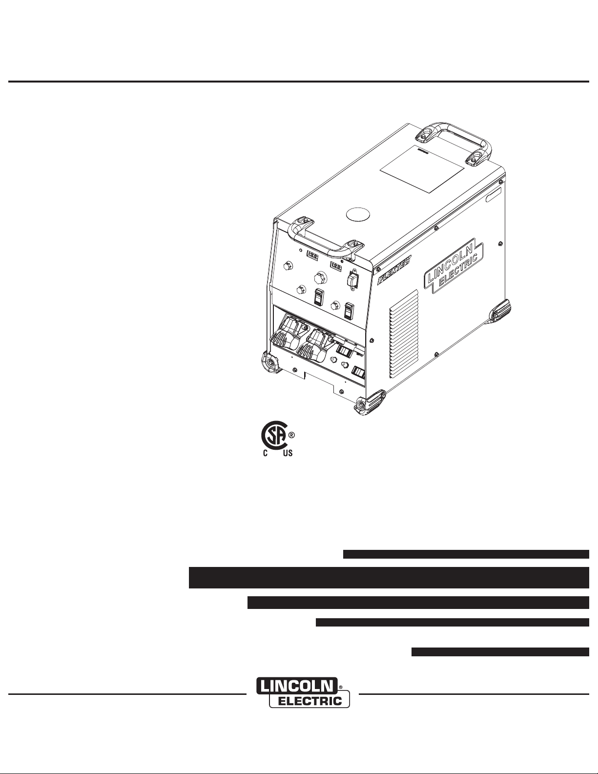
FLEXTEC™650
Cleveland, Ohio 44117-1199 U.S.A. TEL: 216.481.8100 FAX: 216.486.1751 WEB SITE: www.lincolnelectric.com
OPERATORʼS MANUAL
Copyright © Lincoln Global Inc.
• World's Leader in Welding and Cutting Products •
• Sales and Service through Subsidiaries and Distributors Worldwide •
Page 2
i
SAFETY
i
WARNING
CALIFORNIA PROPOSITION 65 WARNINGS
Diesel engine exhaust and some of its constituents
are known to the State of California to cause cancer, birth defects, and other reproductive harm.
The Above For Diesel Engines
ARC WELDING CAN BE HAZARDOUS. PROTECT YOURSELF AND OTHERS FROM POSSIBLE SERIOUS INJURY OR DEATH.
KEEP CHILDREN AWAY. PACEMAKER WEARERS SHOULD CONSULT WITH THEIR DOCTOR BEFORE OPERATING.
Read and understand the following safety highlights. For additional safety information, it is strongly recommended that you
purchase a copy of “Safety in Welding & Cutting - ANSI Standard Z49.1” from the American Welding Society, P.O. Box
351040, Miami, Florida 33135 or CSA Standard W117.2-1974. A Free copy of “Arc Welding Safety” booklet E205 is available
from the Lincoln Electric Company, 22801 St. Clair Avenue, Cleveland, Ohio 44117-1199.
BE SURE THAT ALL INSTALLATION, OPERATION, MAINTENANCE AND REPAIR PROCEDURES ARE
PERFORMED ONLY BY QUALIFIED INDIVIDUALS.
The engine exhaust from this product contains
chemicals known to the State of California to cause
cancer, birth defects, or other reproductive harm.
The Above For Gasoline Engines
FOR ENGINE
powered equipment.
1.a. Turn the engine off before troubleshooting and maintenance
work unless the maintenance work requires it to be running.
____________________________________________________
1.b. Operate engines in open, well-ventilated
areas or vent the engine exhaust fumes
outdoors.
____________________________________________________
1.c. Do not add the fuel near an open flame
welding arc or when the engine is running.
Stop the engine and allow it to cool before
refueling to prevent spilled fuel from vaporizing on contact with hot engine parts and
igniting. Do not spill fuel when filling tank. If
fuel is spilled, wipe it up and do not start
engine until fumes have been eliminated.
____________________________________________________
1.d. Keep all equipment safety guards, covers and devices in
position and in good repair.Keep hands, hair, clothing and
tools away from V-belts, gears, fans and all other moving
parts when starting, operating or repairing equipment.
____________________________________________________
1.e. In some cases it may be necessary to remove safety
guards to perform required maintenance. Remove
guards only when necessary and replace them when the
maintenance requiring their removal is complete.
Always use the greatest care when working near moving
parts.
___________________________________________________
1.f. Do not put your hands near the engine fan.
Do not attempt to override the governor or
idler by pushing on the throttle control rods
while the engine is running.
1.h. To avoid scalding, do not remove the
radiator pressure cap when the engine is
hot.
ELECTRIC AND
MAGNETIC FIELDS
may be dangerous
2.a. Electric current flowing through any conductor causes
localized Electric and Magnetic Fields (EMF). Welding
current creates EMF fields around welding cables and
welding machines
2.b. EMF fields may interfere with some pacemakers, and
welders having a pacemaker should consult their physician
before welding.
2.c. Exposure to EMF fields in welding may have other health
effects which are now not known.
2.d. All welders should use the following procedures in order to
minimize exposure to EMF fields from the welding circuit:
2.d.1.
Route the electrode and work cables together - Secure
them with tape when possible.
2.d.2. Never coil the electrode lead around your body.
2.d.3. Do not place your body between the electrode and
work cables. If the electrode cable is on your right
side, the work cable should also be on your right side.
___________________________________________________
1.g. To prevent accidentally starting gasoline engines while
turning the engine or welding generator during maintenance
work, disconnect the spark plug wires, distributor cap or
magneto wire as appropriate.
2.d.4. Connect the work cable to the workpiece as close as
possible to the area being welded.
2.d.5. Do not work next to welding power source.
Page 3
ii
SAFETY
ii
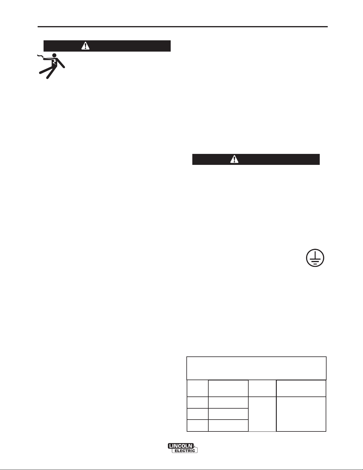
ELECTRIC SHOCK can
kill.
3.a. The electrode and work (or ground) circuits
are electrically “hot” when the welder is on.
Do not touch these “hot” parts with your bare
gloves to insulate hands.
3.b. Insulate yourself from work and ground using dry insulation.
Make certain the insulation is large enough to cover your full
area of physical contact with work and ground.
In addition to the normal safety precautions, if welding
must be performed under electrically hazardous
conditions (in damp locations or while wearing wet
clothing; on metal structures such as floors, gratings or
scaffolds; when in cramped positions such as sitting,
kneeling or lying, if there is a high risk of unavoidable or
accidental contact with the workpiece or ground) use
the following equipment:
• Semiautomatic DC Constant Voltage (Wire) Welder.
• DC Manual (Stick) Welder.
• AC Welder with Reduced Voltage Control.
3.c. In semiautomatic or automatic wire welding, the electrode,
electrode reel, welding head, nozzle or semiautomatic
welding gun are also electrically “hot”.
3.d. Always be sure the work cable makes a good electrical
connection with the metal being welded. The connection
should be as close as possible to the area being welded.
3.e. Ground the work or metal to be welded to a good electrical
(earth) ground.
3.f.
Maintain the electrode holder, work clamp, welding cable and
welding machine in good, safe operating condition. Replace
damaged insulation.
3.g. Never dip the electrode in water for cooling.
3.h. Never simultaneously touch electrically “hot” parts of
electrode holders connected to two welders because voltage
between the two can be the total of the open circuit voltage
of both welders.
3.i. When working above floor level, use a safety belt to protect
yourself from a fall should you get a shock.
3.j. Also see Items 6.c. and 8.
skin or wet clothing. Wear dry, hole-free
ARC RAYS can burn.
4.a. Use a shield with the proper filter and cover
plates to protect your eyes from sparks and
the rays of the arc when welding or observing
open arc welding. Headshield and filter lens
should conform to ANSI Z87. I standards.
4.b. Use suitable clothing made from durable flame-resistant
material to protect your skin and that of your helpers from
the arc rays.
4.c. Protect other nearby personnel with suitable, non-flammable
screening and/or warn them not to watch the arc nor expose
themselves to the arc rays or to hot spatter or metal.
FUMES AND GASES
can be dangerous.
5.a. Welding may produce fumes and gases
hazardous to health. Avoid breathing these
fumes and gases. When welding, keep
your head out of the fume. Use enough
fumes and gases away from the breathing zone. When
welding with electrodes which require special
ventilation such as stainless or hard facing (see
instructions on container or MSDS) or on lead or
cadmium plated steel and other metals or coatings
which produce highly toxic fumes, keep exposure as
low as possible and within applicable OSHA PEL and
ACGIH TLV limits using local exhaust or mechanical
ventilation. In confined spaces or in some circumstances, outdoors, a respirator may be required.
Additional precautions are also required when welding
on galvanized steel.
5. b. The operation of welding fume control equipment is affected
by various factors including proper use and positioning of
the equipment, maintenance of the equipment and the specific welding procedure and application involved. Worker
exposure level should be checked upon installation and
periodically thereafter to be certain it is within applicable
OSHA PEL and ACGIH TLV limits.
5.c.
Do not weld in locations near chlorinated hydrocarbon
coming from degreasing, cleaning or spraying operations.
The heat and rays of the arc can react with solvent vapors
form phosgene, a highly toxic gas, and other irritating products.
5.d. Shielding gases used for arc welding can displace air and
cause injury or death. Always use enough ventilation,
especially in confined areas, to insure breathing air is safe.
ventilation and/or exhaust at the arc to keep
vapors
to
5.e. Read and understand the manufacturer’s instructions for this
equipment and the consumables to be used, including the
material safety data sheet (MSDS) and follow your
employer’s safety practices. MSDS forms are available from
your welding distributor or from the manufacturer.
5.f. Also see item 1.b.
Page 4
iii
SAFETY
iii
WELDING and CUTTING
SPARKS can
cause fire or explosion.
6.a.
Remove fire hazards from the welding area.
If this is not possible, cover them to prevent
Remember that welding sparks and hot
materials from welding can easily go through small cracks
and openings to adjacent areas. Avoid welding near
hydraulic lines. Have a fire extinguisher readily available.
6.b. Where compressed gases are to be used at the job site,
special precautions should be used to prevent hazardous
situations. Refer to “Safety in Welding and Cutting” (ANSI
Standard Z49.1) and the operating information for the
equipment being used.
6.c. When not welding, make certain no part of the electrode
circuit is touching the work or ground. Accidental contact
can cause overheating and create a fire hazard.
6.d. Do not heat, cut or weld tanks, drums or containers until the
proper steps have been taken to insure that such procedures
will not cause flammable or toxic vapors from substances
inside. They can cause an explosion even
been “cleaned”. For information, purchase “Recommended
Safe Practices for the
Containers and Piping That Have Held Hazardous
Substances”, AWS F4.1 from the American Welding Society
(see address above).
6.e. Vent hollow castings or containers before heating, cutting or
welding. They may explode.
Sparks and spatter are thrown from the welding arc. Wear oil
6.f.
free protective garments such as leather gloves, heavy shirt,
cuffless trousers, high shoes and a cap over your hair. Wear
ear plugs when welding out of position or in confined places.
Always wear safety glasses with side shields when in a
welding area.
6.g. Connect the work cable to the work as close to the welding
area as practical. Work cables connected to the building
framework or other locations away from the welding area
increase the possibility of the welding current passing
through lifting chains, crane cables or other alternate circuits. This can create fire hazards or overheat lifting chains
or cables until they fail.
6.h. Also see item 1.c.
the welding sparks from starting a fire.
though
they have
Preparation
for Welding and Cutting of
CYLINDER may explode
if damaged.
7.a.Use only compressed gas cylinders
containing the correct shielding gas for the
process used and properly operating
regulators designed for the gas and
pressure used. All hoses, fittings, etc. should be suitable for
the application and maintained in good condition.
7.b. Always keep cylinders in an upright position securely
chained to an undercarriage or fixed support.
7.c. Cylinders should be located:
• Away from areas where they may be struck or subjected to
physical damage.
• A safe distance from arc welding or cutting operations and
any other source of heat, sparks, or flame.
7.d. Never allow the electrode, electrode holder or any other
electrically “hot” parts to touch a cylinder.
7.e. Keep your head and face away from the cylinder valve outlet
when opening the cylinder valve.
7.f. Valve protection caps should always be in place and hand
tight except when the cylinder is in use or connected for
use.
7.g. Read and follow the instructions on compressed gas
cylinders, associated equipment, and CGA publication P-l,
“Precautions for Safe Handling of Compressed Gases in
Cylinders,” available from the Compressed Gas Association
1235 Jefferson Davis Highway, Arlington, VA 22202.
FOR ELECTRICALLY
powered equipment.
8.a. Turn off input power using the disconnect
switch at the fuse box before working on
the equipment.
8.b. Install equipment in accordance with the U.S. National
Electrical Code, all local codes and the manufacturer’s
recommendations.
8.c. Ground the equipment in accordance with the U.S. National
Electrical Code and the manufacturer’s recommendations.
6.I. Read and follow NFPA 51B “ Standard for Fire Prevention
During Welding, Cutting and Other Hot Work”, available
from NFPA, 1 Batterymarch Park, PO box 9101, Quincy, Ma
022690-9101.
6.j. Do not use a welding power source for pipe thawing.
Refer to http://www.lincolnelectric.com/safety for additional safety information.
Page 5

iv
SAFETY
iv
PRÉCAUTIONS DE SÛRETÉ
Pour votre propre protection lire et observer toutes les instructions
et les précautions de sûreté specifiques qui parraissent dans ce
manuel aussi bien que les précautions de sûreté générales suivantes:
Sûreté Pour Soudage A LʼArc
1. Protegez-vous contre la secousse électrique:
a. Les circuits à lʼélectrode et à la piéce sont sous tension
quand la machine à souder est en marche. Eviter toujours
tout contact entre les parties sous tension et la peau nue
ou les vétements mouillés. Porter des gants secs et sans
trous pour isoler les mains.
b. Faire trés attention de bien sʼisoler de la masse quand on
soude dans des endroits humides, ou sur un plancher
metallique ou des grilles metalliques, principalement dans
les positions assis ou couché pour lesquelles une grande
partie du corps peut être en contact avec la masse.
c. Maintenir le porte-électrode, la pince de masse, le câble
de soudage et la machine à souder en bon et sûr état
defonctionnement.
d.Ne jamais plonger le porte-électrode dans lʼeau pour le
refroidir.
e. Ne jamais toucher simultanément les parties sous tension
des porte-électrodes connectés à deux machines à souder
parce que la tension entre les deux pinces peut être le
total de la tension à vide des deux machines.
f. Si on utilise la machine à souder comme une source de
courant pour soudage semi-automatique, ces precautions
pour le porte-électrode sʼapplicuent aussi au pistolet de
soudage.
6. Eloigner les matériaux inflammables ou les recouvrir afin de
prévenir tout risque dʼincendie dû aux étincelles.
7. Quand on ne soude pas, poser la pince à une endroit isolé de
la masse. Un court-circuit accidental peut provoquer un
échauffement et un risque dʼincendie.
8. Sʼassurer que la masse est connectée le plus prés possible
de la zone de travail quʼil est pratique de le faire. Si on place
la masse sur la charpente de la construction ou dʼautres
endroits éloignés de la zone de travail, on augmente le risque
de voir passer le courant de soudage par les chaines de levage, câbles de grue, ou autres circuits. Cela peut provoquer
des risques dʼincendie ou dʼechauffement des chaines et des
câbles jusquʼà ce quʼils se rompent.
9. Assurer une ventilation suffisante dans la zone de soudage.
Ceci est particuliérement important pour le soudage de tôles
galvanisées plombées, ou cadmiées ou tout autre métal qui
produit des fumeés toxiques.
10. Ne pas souder en présence de vapeurs de chlore provenant
dʼopérations de dégraissage, nettoyage ou pistolage. La
chaleur ou les rayons de lʼarc peuvent réagir avec les vapeurs
du solvant pour produire du phosgéne (gas fortement toxique)
ou autres produits irritants.
11. Pour obtenir de plus amples renseignements sur la sûreté,
voir le code “Code for safety in welding and cutting” CSA
Standard W 117.2-1974.
2. Dans le cas de travail au dessus du niveau du sol, se protéger
contre les chutes dans le cas ou on recoit un choc. Ne jamais
enrouler le câble-électrode autour de nʼimporte quelle partie
du corps.
3. Un coup dʼarc peut être plus sévère quʼun coup de soliel,
donc:
a. Utiliser un bon masque avec un verre filtrant approprié
ainsi quʼun verre blanc afin de se protéger les yeux du rayonnement de lʼarc et des projections quand on soude ou
quand on regarde lʼarc.
b. Porter des vêtements convenables afin de protéger la
peau de soudeur et des aides contre le rayonnement de
lʻarc.
c. Protéger lʼautre personnel travaillant à proximité au
soudage à lʼaide dʼécrans appropriés et non-inflammables.
4. Des gouttes de laitier en fusion sont émises de lʼarc de
soudage. Se protéger avec des vêtements de protection libres
de lʼhuile, tels que les gants en cuir, chemise épaisse, pantalons sans revers, et chaussures montantes.
5. Toujours porter des lunettes de sécurité dans la zone de
soudage. Utiliser des lunettes avec écrans lateraux dans les
zones où lʼon pique le laitier.
PRÉCAUTIONS DE SÛRETÉ POUR
LES MACHINES À SOUDER À
TRANSFORMATEUR ET À
REDRESSEUR
1. Relier à la terre le chassis du poste conformement au code de
lʼélectricité et aux recommendations du fabricant. Le dispositif
de montage ou la piece à souder doit être branché à une
bonne mise à la terre.
2. Autant que possible, Iʼinstallation et lʼentretien du poste seront
effectués par un électricien qualifié.
3. Avant de faires des travaux à lʼinterieur de poste, la debrancher à lʼinterrupteur à la boite de fusibles.
4. Garder tous les couvercles et dispositifs de sûreté à leur
place.
Page 6
Thank You
vv
for selecting a QUALITY product by Lincoln Electric. We want you
to take pride in operating this Lincoln Electric Company product
••• as much pride as we have in bringing this product to you!
The business of The Lincoln Electric Company is manufacturing and selling high quality welding equipment, consumables, and cutting equipment. Our challenge is to meet the needs of our customers and to exceed their expectations. On occasion, purchasers may ask Lincoln
Electric for advice or information about their use of our products. We respond to our customers based on the best information in our possession at that time. Lincoln Electric is not in a position to warrant or guarantee such advice, and assumes no liability, with respect to such information or advice. We expressly disclaim any warranty of any kind, including any warranty of fitness for any customerʼs particular purpose,
with respect to such information or advice. As a matter of practical consideration, we also cannot assume any responsibility for updating or
correcting any such information or advice once it has been given, nor does the provision of information or advice create, expand or alter any
warranty with respect to the sale of our products.
Lincoln Electric is a responsive manufacturer, but the selection and use of specific products sold by Lincoln Electric is solely within the control
of, and remains the sole responsibility of the customer. Many variables beyond the control of Lincoln Electric affect the results obtained in
applying these types of fabrication methods and service requirements.
Subject to Change – This information is accurate to the best of our knowledge at the time of printing. Please refer to www.lincolnelectric.com
for any updated information.
CUSTOMER ASSISTANCE POLICY
Please Examine Carton and Equipment For Damage Immediately
When this equipment is shipped, title passes to the purchaser upon receipt by the carrier. Consequently, Claims
for material damaged in shipment must be made by the purchaser against the transportation company at the
time the shipment is received.
Please record your equipment identification information below for future reference. This information can be
found on your machine nameplate.
Product _________________________________________________________________________________
Model Number ___________________________________________________________________________
Code Number or Date Code_________________________________________________________________
Serial Number____________________________________________________________________________
Date Purchased___________________________________________________________________________
Where Purchased_________________________________________________________________________
Whenever you request replacement parts or information on this equipment, always supply the information you
have recorded above. The code number is especially important when identifying the correct replacement parts.
On-Line Product Registration
- Register your machine with Lincoln Electric either via fax or over the Internet.
• For faxing: Complete the form on the back of the warranty statement included in the literature packet
accompanying this machine and fax the form per the instructions printed on it.
• For On-Line Registration: Go to our
Your Product”. Please complete the form and submit your registration.
Read this Operators Manual completely before attempting to use this equipment. Save this manual and keep it
handy for quick reference. Pay particular attention to the safety instructions we have provided for your protection.
The level of seriousness to be applied to each is explained below:
WEB SITE at www.lincolnelectric.com. Choose “Support” and then “Register
WARNING
This statement appears where the information must be followed exactly to avoid serious personal injury or loss of life.
CAUTION
This statement appears where the information must be followed to avoid minor personal injury or damage to this equipment.
Page 7

vi vi
Installation .......................................................................................................Section A
Technical Specifications ........................................................................................A-1
Welding Process, Physical Dimensions.................................................................A-2
Safety Precautions.................................................................................................A-3
VRD™ (Voltage Reduction Device) ..............................................................................A-3
Select Suitable Location..................................................................................A-3
Lifting...............................................................................................................A-3
Stacking ..........................................................................................................A-3
Environmental Limitations ...............................................................................A-3
Input and Grounding Connections ..................................................................A-3
High Frequency Protection..............................................................................A-3
High Temperature Operation.................................................................................A-3
Input Connection ...................................................................................................A-4
Input Fuse and Supply Wire Considerations .........................................................A-4
Input Voltage Selection..........................................................................................A-4
Cable Connections ................................................................................................A-5
Recommended Electrode and Work Cable for Arc Welding..................................A-6
Output Cable Guidelines........................................................................................A-6
Control Cable Connections, Paralleling.................................................................A-7
Connection Diagrams Flextec 650 to Wire Feeders and Tractor...........A-8 thru A-12
________________________________________________________________________
TABLE OF CONTENTS
Page
Operation .........................................................................................................Section B
Safety Precautions ................................................................................................B-1
Graphic Symbols............................................................................................B-1, B-2
Product Description ..............................................................................................B-2
Duty Cycle .............................................................................................................B-2
Design Features ....................................................................................................B-2
Recommended Processes and Equipment ...........................................................B-3
Case Front Controls...............................................................................................B-4
Case Back Controls...............................................................................................B-5
Internal Controls ....................................................................................................B-6
Power-Up Sequence..............................................................................................B-7
Common Welding Procedures, Weld Controls and Displays.................B-7 thru B-10
_______________________________________________________________________
Accessories.....................................................................................................Section C
Options / Accessories............................................................................................C-1
________________________________________________________________________
Maintenance ....................................................................................................Section D
Safety Precautions ................................................................................................D-1
Visual Inspection ...................................................................................................D-1
Routine Maintenance.............................................................................................D-1
Periodic Maintenance............................................................................................D-1
________________________________________________________________________
Section E ..............................................................................................Troubleshooting
How to Use Troubleshooting Guide.......................................................................E-1
Troubleshooting Guide ..........................................................................................E-2
Error Codes....................................................................................................E-3, E-4
________________________________________________________________________
Wiring Diagram and Dimension Print ..............................................................Section F
________________________________________________________________________
Parts List .....................................................................................................P-686 Series
________________________________________________________________________
Page 8
A-1
INSTALLATION
A-1
TECHNICAL SPECIFICATIONS -
POWER SOURCE-INPUT VOLTAGE AND CURRENT
Model
K3060-1
GMAW (CV)
GTAW (CC)
SMAW (CC)
FCAW-GS (CV)
FCAW-SS (CV)
Duty Cycle
60% rating
100% rating
Process
Input Voltage ± 10%
380 / 460 / 575 / 3 / 50 / 60
Duty Cycle
60%
100%
60%
100%
60%
100%
60%
100%
60%
100%
FLEXTEC™ 650
Input Amperes
61 / 50 / 40
57 / 47 / 38
RATED OUTPUT*
Amperes
750
*
650
*
750
650
750
*
650
*
750
*
650
*
750
*
650
*
Idle Power
(W)
230 MAX.( Fan On)
100 MAX. (Fan Off)
Volts at Rated Amperes
44V
34V
44V
Power Factor @
Rated Output
88%
60%
SAW (CV)
100%
750
650
*
*
* Output is limited to 600A / 100% and 700A / 60% when used with K3091-1 Multi-Process Switch.
RECOMMENDED INPUT WIRE AND FUSE SIZES
(mm)
4(25)
4(25)
6(16)
(3)
Type 75°C Copper
Wire in Conduit
AWG (mm
4(25)
6(16)
8 (10)
COPPER GROUNDING
CONDUCTOR
2
)
AWG (mm
8 (10)
8 (10)
10 (6)
VOLTAGE
50/60Hz
380/3/50
460/3/60
575/3/60
(1)
Cord and Fuse Sizes based upon the U.S. National Electric Code and maximum output for 40°C (104°) ambient.
(2)
Also called “inverse time” or “thermal/magnetic” circuit breakers; circuit breakers that have a delay in tripping action that decreases as the
magnitude of current increases.
(3)
Type SJ cord or similar in 30°C ambient.
Maximum
Input
Amperes
70 A
58 A
46 A
Cord Size
AWG SIZES
(1)
Fuse (Super Lag) or
2
)
Breaker Size
90
80
60
(2)
FLEXTEC™ 650
Page 9
A-2
PROCESS
INSTALLATION
WELDING PROCESS
OUTPUT RANGE (AMPERES)
OCV (Uo)
A-2
OCV (Ur)
GMAW (CV)
GTAW (CC)
SMAW (CC)
FCAW-GS (CV)
FCAW-SS (CV)
SAW (CV)
40-815
10-815
15-815
40-815
40-815
40-815
PHYSICAL DIMENSIONS
MODEL
K3060-1
HEIGHT
21.8 in (554 mm)
WIDTH
16.14 in (410 mm)
TEMPERATURE RANGES
OPERATING TEMPERATURE RANGE
Environmentally Hardened: 14°F to 131°F (-10°C to 55°C**)
IP23 180º(H) Insulation Class
* Weight does not include input cord.
** Power Source is de-rated at temperatures above 40C.
AUXILIARY RECONNECT INPUT RANGES
"A" LEAD
POSITION
VAC INPUT
LIMITS (VOLTS)
60
24
60
60
60
60
DEPTH
29.33 in (745 mm)
STORAGE TEMPERATURE RANGE
Environmentally Hardened: -40°F to 185°F (-40°C to 85°C)
VRD
Disabled
165lbs (74.8kg)*
Enabled
--15
15
---
---
---
WEIGHT
VRD
380 Volt
Reconnect
460 Volt
Reconnect
575 Volt
Reconnect
Low Limit
High Limit
Low Limit
High Limit
Low Limit
High Limit
340 Vac
420 Vac
390 Vac
505 Vac
485 Vac
620 Vac
340 Vac
455 Vac
390 Vac
520 Vac
485 Vac
655 Vac
FLEXTEC™ 650
Page 10
A-3
INSTALLATION
SAFETY PRECAUTIONS
WARNING
ELECTRIC SHOCK can kill.
ONLY QUALIFIED PERSONNEL
SHOULD PERFORM THIS INSTALLATION.
• TURN OFF INPUT POWER TO THE POWER
SOURCE AT THE DISCONNECT SWITCH OR
FUSE BOX BEFORE WORKING ON THIS
EQUIPMENT. TURN OFF THE INPUT POWER
TO ANY OTHER EQUIPMENT CONNECTED TO
THE WELDING SYSTEM AT THE DISCONNECT
SWITCH OR FUSE BOX BEFORE WORKING ON
THE EQUIPMENT.
• DO NOT TOUCH ELECTRICALLY HOT PARTS.
• ALWAYS CONNECT THE FLEXTEC™ 650
GROUNDING LUG (LOCATED INSIDE THE
RECONNECT INPUT ACCESS DOOR) TO A
PROPER SAFETY (EARTH) GROUND.
----------------------------------------------------------------------
VRD™ (VOLTAGE REDUCTION DEVICE)
The VRD™ feature provides additional safety in the CCStick mode. The VRD™ reduces the OCV (Open Circuit
Voltage) at the welding output terminals while not welding to
less than 35VDC peak.
A-3
When using a crane or overhead device to lift using
the handles, a lifting strap should be connected to
both handles. Do not attempt to lift the FLEXTEC™
650 with accessories attached to it.
STACKING
Multiple FLEXTEC™ 650ʼs cannot be stacked.
ENVIRONMENTAL LIMITATIONS
The FLEXTEC™ 650 is IP23 rated for use in an outdoor environment. The FLEXTEC™ 650 should not be
subjected to falling water during use nor should any
parts of it be submerged in water. Doing so may
cause improper operation as well as pose a safety
hazard. The best practice is to keep the machine in a
dry, sheltered area.
CAUTION
Do not mount the FLEXTEC™ 650 over combustible surfaces. Where there is a combustible
surface directly under stationary or fixed electrical
equipment, that surface shall be covered with a
steel plate at least .060” (1.6mm) thick, which shall
extend not less than 5.90” (150mm) beyond the
equipment on all sides.
-----------------------------------------------------------------------
INPUT AND GROUNDING CONNECTIONS
The VRD™ requires that the welding cable connections be
kept in good electrical condition because poor connections
will contribute to poor starting. Having good electrical connections also limits the possibility of other safety issues
such as heat-generated damage, burns and fires.
The machine is shipped with VRD™ “Disabled”. The VRD™
function can be disabled or enabled via dip switches on the
control P.C. board. Dip switch setting will differ depending
on input voltage.
The control board and dip switches can be accessed by
removing the case top and side as shown in the Operation
Section figure B.3.
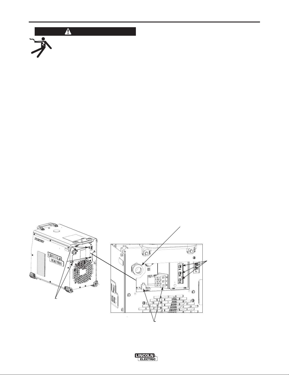
SELECT SUITABLE LOCATION
LOCATION AND VENTILATION FOR COOLING
Place the welder where clean cooling air can freely
circulate in through the rear louvers and out through
the case sides. Dirt, dust, or any foreign material that
can be drawn into the welder should be kept at a minimum. Failure to observe these precautions can result
in excessive operating temperatures and nuisance
shutdowns.
LIFTING
The FLEXTEC™ 650 has 2 lifting eyelets and 2 handles that can be used to lift the machine. Both handles
or both eyelets should be used when lifting the FLEXTEC™ 650.
FLEXTEC™ 650
MACHINE GROUNDING
The frame of the welder must be grounded.
A ground terminal marked with the symbol
shown is located inside the reconnect/input
connection area for this purpose. See your local and
national electrical codes for proper grounding methods.
HIGH FREQUENCY PROTECTION
Locate the FLEXTEC™ 650 away from radio controlled machinery. The normal operation of the FLEXTEC™ 650 may adversely affect the operation of RF
controlled equipment, which may result in bodily injury
or damage to the equipment.
HIGH TEMPERATURE OPERATION
WELDER OUTPUT RATINGS AT 55°C
ELEVATED TEMPERATURES
AMPS
600
650
750
DUTY CYCLE
100%
50%
30%
VOLTS
44V
TEMPERATURES
55°C
Page 11
A-4
INSTALLATION
WARNING
ELECTRIC SHOCK can kill.
ONLY A QUALIFIED ELECTRICIAN
SHOULD CONNECT THE INPUT
LEADS TO THE FLEXTEC™ 650.
CONNECTIONS SHOULD BE MADE IN ACCORDANCE WITH ALL LOCAL AND NATIONAL
ELECTRICAL CODES AND THE CONNECTION
DIAGRAM LOCATED ON THE INSIDE OF THE
RECONNECT/INPUT ACCESS DOOR OF THE
MACHINE. FAILURE TO DO SO MAY RESULT
IN BODILY INJURY OR DEATH.
----------------------------------------------------------------------
INPUT CONNECTION
(See Figure A.1)
Use a three-phase supply line. A 1.75 inch (45 mm)
diameter access hole for the input supply is located on
the case back. Remove the reconnect access panel
located on the case back and connect W, V, U and
ground according to the Input Supply Connection
Diagram decal.
A-4
INPUT FUSE AND SUPPLY WIRE
CONSIDERATIONS
Refer to Specification in this Installation Section for
recommended fuse, wire sizes and type of the copper
wires. Fuse the input circuit with the recommended
super lag fuse or delay type breakers (also called
"inverse time" or "thermal/magnetic" circuit breakers).
Choose input and grounding wire size according to
local or national electrical codes. Using input wire
sizes, fuses or circuit breakers smaller than recommended may result in "nuisance" shut-offs from
welder inrush currents, even if the machine is not
being used at high currents.
INPUT VOLTAGE SELECTION
Welders are shipped connected for 460 Volt input
voltage. To move this connection to a different input
voltage, see Figure A.1 which is illustrated below.
Refer to Auxiliary Reconnect Input Ranges table in
the Technical Specification Section. If the Auxiliary
lead (indicated as ʻAʼ) is placed in the wrong position
and power is applied to the machine, the machine will
protect itself and display an error message:
• "Err" "713 or 714" will be shown on the display.
• The control board and switch boards will blink out
error 713 or 714 on their status leds.
• The weld output will be turned off and the control
board will force itself into an idle state.
• The machine will need to have the misconnect
condition removed before it will recover. Power
must be removed prior to changing reconnect position.
REMOVE FOUR SCREWS
AND ACCESS PANEL
FIGURE A.1
POWER SUPPLY TERMINAL BLOCK
• Line Cord/Cable attaches here.
• A ground terminal marked with the symbol shown
is provided separate from this block for connecting the ground
lead of the line cord. (See your local and national electrical
codes for proper grounding methods.)
FLEXTEC™ 650
POWER SUPPLY ACCESS HOLE
• Route input power cable through this hole.
• Strain relief required. See your local and
National Electrical codes for proper strain relief.
RECONNECT TERMINAL BLOCK
• Reconnects auxiliary
transformer for the
proper input voltage.
Page 12
A-5
INSTALLATION
CABLE CONNECTIONS
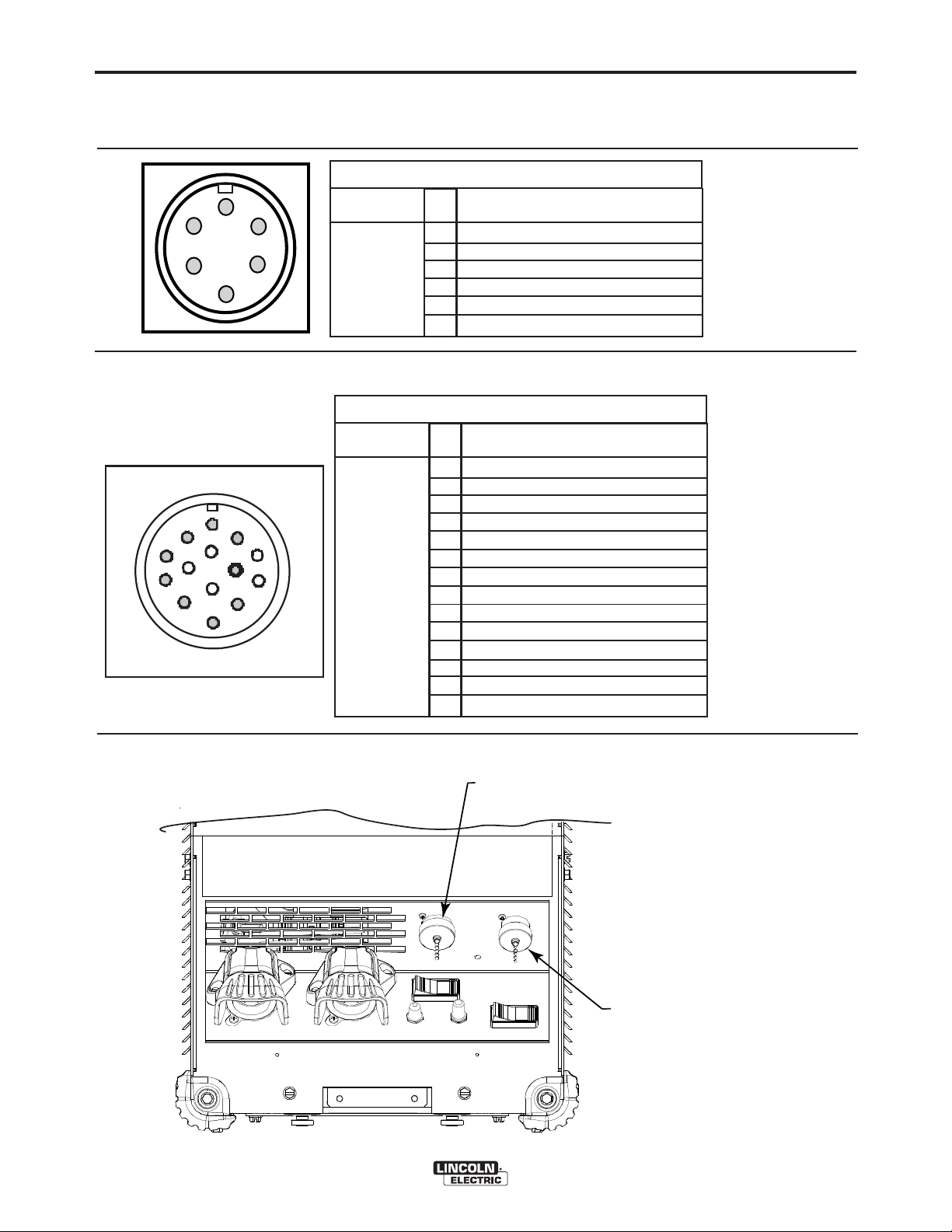
See FIGURE A.2 for locating 6-pin and 14-pin connectors on the front of the FLEXTEC™ 650.
6-PIN REMOTE CONTROL CONNECTOR
A-5
F
E
A
D
C
G
F
M
E
L
D
B
H
I
N
J
K
A
B
C
Function
6-pin remote
control connector for
remote or
hand/foot
amptrol.
14-PIN CONNECTOR FOR WIRE FEEDER
Function
14 pin connector for
wire feeder
connectivity.
Pin
77 Remote potentiometer, 10K
A
76 Remote potentiometer, wiper
B
75 Remote potentiometer, common
C
Trigger, common
D
Trigger, input
E
Ground
F
Pin
115 VAC
A
Ground
B
Trigger, Common
C
Trigger input
D
77 Remote potentiometer, 10K
E
76 Remote potentiometer, wiper
F
75 Remote potentiometer, common
G
Voltage Sense (21)
H
Motor (42 VAC)
I
115 VAC
J
Motor (42 VAC)
K
L
M
N
Wiring
Wiring
FIGURE A.2
14-PIN CONNECTOR
FOR WIRE FEEDER
FLEXTEC™ 650
6-PIN REMOTE
CONTROL CONNECTOR
Page 13

A-6
INSTALLATION
A-6
RECOMMENDED ELECTRODE AND
WORK CABLE SIZES FOR ARC WELDING
General Guidelines
Connect the electrode and work cables between the
appropriate output studs of the FLEXTEC™ 650 per
the following guidelines:
• Most welding applications run with the electrode
being positive (+). For those applications, connect
the electrode cable between the wire drive feed
plate and the positive (+) output stud on the power
source. Connect a work lead from the negative (-)
power source output stud to the work piece.
• When negative electrode polarity is required, such
as in some Innershield applications, reverse the output connections at the power source (electrode
cable to the negative (-) stud, and work cable to the
positive (+) stud).
The following recommendations apply to all output
polarities and weld modes:
• Select the appropriate size cables per the
“Output Cable Guidelines” (See Table A.1).
Excessive voltage drops caused by undersized
welding cables and poor connections often result in
unsatisfactory welding performance. Always use the
largest welding cables (electrode and work) that are
practical, and be sure all connections are clean and
tight.
Note: Excessive heat in the weld circuit indicates
undersized cables and/or bad connections.
• Route all cables directly to the work and wire
feeder, avoid excessive lengths and do not coil
excess cable. Route the electrode and work cables
in close proximity to one another to minimize the
loop area and therefore the inductance of the weld
circuit.
• Always weld in a direction away from the work
(ground) connection.
TABLE A.1
OUTPUT CABLE GUIDELINES
CABLE SIZES FOR COMBINED LENGTHS OF ELECTRODE AND WORK CABLES
AMPERES
200
200
250
250
250
250
300
300
350
400
400
500
600
600
600
650
650
700
800
800
** Tabled values are for operation at ambient temperatures of 104°F(40°C) and below. Applications above 104°F(40°C) may require cables
larger than recommended, or cables rated higher than 167°F(75°C).
PERCENT
DUTY
CYCLE
60
100
30
40
60
100
60
100
40
60
100
60
60
80
100
60
80
100
80
100
0 to 50Ft.
(0 to15m)
2
2
3
2
1
1
1
2/0
1/0
2/0
3/0
2/0
3/0
2-1/0
2-1/0
3/0
2-1/0
2-2/0
3-1/0
2-3/0
(RUBBER COVERED COPPER - RATED 167°F or 75°C)**
50 to 100Ft.
(15 to 30m)
2
2
3
2
1
1
1
2/0
1/0
2/0
3/0
2/0
3/0
2-1/0
2-1/0
3/0
2-1/0
2-2/0
3-1/0
2-3/0
100 to 150 Ft.
(30 to 46m)
2
2
2
1
1
1
1
2/0
2/0
2/0
3/0
3/0
3/0
2-1/0
2-1/0
4/0
2-1/0
2-3/0
3-1/0
2-3/0
150 to 200 Ft.
(46 to 61m)
1
1
1
1
1
1
1/0
2/0
2/0
3/0
3/0
3/0
4/0
2-2/0
2-2/0
2-2/0
2-2/0
2-3/0
2-3/0
2-3/0
200 to 250 Ft.
(61 to 76m)
1/0
1/0
1/0
1/0
1/0
1/0
2/0
3/0
3/0
4/0
4/0
4/0
2-3/0
2-3/0
2-3/0
2-3/0
2-3/0
2-4/0
2-4/0
2-4/0
FLEXTEC™ 650
Page 14

A-7
POSITIVE
AT WWORK PPIECE
POSITIVE
AT WWORK PPIECE
POSITIVE
A
NEGATIVEVE
W
V
U
T
AL
V
W
ES
A
NEEGGAATTIIVEVE
TO GGROO
UND
ELECTRIC
CODE
PER
NATIONAL
U
GND
G
VE
TO GGROUNUND
GND
PER NNATIONAL
ELECTRICAL
C
ODE
BLOCK
655
0
)
C
0
)
T
AL
K
W
V
U
V
W
ES
U
INSTALLATION
A-7
CONTROL CABLE CONNECTIONS
General Guidelines
Genuine Lincoln control cables should be used at all
times (except where noted otherwise). Lincoln cables
are specifically designed for the communication and
power needs of the FLEXTEC™ 650. Most are
designed to be connected end to end for ease of
extension. Generally, it is recommended that the total
length not exceed 100 feet (30.5 m). The use of nonstandard cables, especially in lengths greater than 25
feet, can lead to communication problems (system
shutdowns), poor motor acceleration (poor arc starting), and low wire driving force (wire feeding problems). Always use the shortest length of control cable
possible, and DO NOT coil excess cable.
FIGURE A.3
PARALLELING DIAGRAM
IINNPPUUT
TTEERRMMIINNAL
FFLLEEXXTTEECC 6
((MMAACCHHIINNEE #1#1)
0
Regarding cable placement, best results will be
obtained when control cables are routed separate
from the weld cables. This minimizes the possibility of
interference between the high currents flowing
through the weld cables, and the low level signals in
the control cables.
PARALLELING
FLEXTEC™ 650 power sources may be paralleled for
increased output requirements. No kit is required for
paralleling of FLEXTEC™ 650 power sources. The
FLEXTEC™ 650 can only be paralleled for constant
current processes (mode switch must be in the SMAW
position). Connect the power sources as shown, and
set the output control of each power source to one
half of the desired arc current. (See Figure A.3)
W
U
A
PE
N
IINNPPUUTT LLIINNES
W
V
UN
AAL C
NNEEG
N
AATTIIVE
FFLLEEXXTTEEC
((MMAACCHHIINNEE #2#2)
IINNPPUUT
TTEERRMMIINNAL
BBLLOOCCK
66550
FLEXTEC™ 650
W
U
IINNPPUUTT LLIINNES
A
W
V
U
G
C
O
Page 15

A-8
CONNECTING LF-72 AND LF-74 TO THE FLEXTEC™ 650
FLEXTEC™-650
WELD MODE
INSTALLATION
14-PIN CONTROL CABLE K1797-XX
ELECTRODE
WORK
CONTROL SETTING
CV, CV-INNERSHIELD
A-8
WIRE FEEDER
LF-72
LF-74
WELD TERMINALS
REMOTE/LOCAL
VOLTMETER POLARITY
OFF
LOCAL
(REMOTE IF K2329-1 INSTALLED)
PROCESS DEPENDENT
FLEXTEC™ 650
Page 16

A-9
INSTALLATION
CONNECTING LN-10 AND DH-10 TO THE FLEXTEC™ 650
WIRE FEEDER
A-9
14-PIN CONTROL CABLE K1501-XX
FLEXTEC™-650
ELECTRODE
WORK
CONTROL SETTING
WELD MODE
WELD TERMINALS
REMOTE/LOCAL
VOLTMETER POLARITY
LN-10,DH-10 CONTROL SWITCH
SETUP
Initial set up of the LN-10, DH-10 control for the system components being used and for general operator
preferences is done using a pair of 8-pole DIP switches located inside the LN-10, DH-10 control box.
LN-10
DH-10
CV, CV-INNERSHIELD
OFF
REMOTE
PROCESS DEPENDENT
Setting the DIP Switches
The DIP switches are each labeled with an “ON”
arrow showing the on direction for each of the 8 individual switches in each DIP switch (S1 and S2). The
functions of these switches are also labeled and set
as described below:
Setup DIP Switch Access
1) Shut off the input power to the LN-10, DH-10 control by turning off the power at the welding power
source it is connected to.
2) Remove the two screws on the top of the LN-10,
DH-10 control box door and swing the door down
to open.
3) Locate the two 8-pole DIP switches, near the top
left corner of the LN-10, DH-10 Control P.C. board,
labeled S1 and S2.
4) Switch settings are only programmed during input
power-up restoration.
FLEXTEC™ 650
Pwr Sources
ON
12 3 4567 8
S1
Head
S1
Pwr Sources
ON
12 345678
S1
S1
Page 17

A-10
FLEXTEC™-650
INSTALLATION
CONNECTING LN-25 PRO, LN-25 PIPE, ACTIVE8 TO THE FLEXTEC™ 650
WIRE FEEDER
LN-25 PRO
ELECTRODE
WORK
CONTROL SETTING
WELD MODE
LN-25 PIPE
ACTIVE8
WORK CLIP
CV, CV-INNERSHIELD
A-10
WELD TERMINALS
REMOTE/LOCAL
VOLTMETER POLARITY
PROCESS DEPENDENT
ON
LOCAL
CONNECTING LN-25 PRO DUAL POWER TO THE FLEXTEC™ 650
WIRE FEEDER
FLEXTEC™-650
CONTROL CABLE K1797-XX
ELECTRODE
WORK
*
LN-25 PRO
DUAL POWER
CONTROL SETTING
WELD MODE
WELD TERMINALS
REMOTE/LOCAL
VOLTMETER POLARITY
*CONTROL CABLE SETUP SHOWN. REFER TO LN-25 PRO CONNECTION DIAGRAM IF SETTING UP
"ACROSS-THE-ARC" FEEDER.
FLEXTEC™ 650
CV, CV-INNERSHIELD
OFF
REMOTE
PROCESS DEPENDENT
Page 18

A-11
FLEXTEC™-650
WELD MODE
INSTALLATION
CONNECTING LN-7 TO THE FLEXTEC™ 650
WIRE FEEDER
14-PIN CONTROL CABLE K1818-XX
ELECTRODE
WORK
CONTROL SETTING
CV, CV-INNERSHIELD
LN-7
A-11
WELD TERMINALS
REMOTE/LOCAL
VOLTMETER POLARITY
CONNECTING LN-8 AND LN-9 TO THE FLEXTEC™ 650
FLEXTEC™-650
LOCAL
PROCESS DEPENDENT
14-PIN CONTROL CABLE K1820-XX
ELECTRODE
WORK
OFF
WIRE FEEDER
LN-8
LN-9
WELD MODE
WELD TERMINALS
REMOTE/LOCAL
VOLTMETER POLARITY
CONTROL SETTING
CV, CV-INNERSHIELD
OFF
REMOTE
PROCESS DEPENDENT
FLEXTEC™ 650
Page 19

A-12
INSTALLATION
CONNECTING NA-3, NA-5 TO THE FLEXTEC™ 650
WIRE FEEDER
A-12
14-PIN CONTROL CABLE K1820-XX
FLEXTEC™-650
FOR NA-3, NA-4 WIRE FEEDERS ONLY:
- MOVE JUMPER LEAD ON VARIABLE VOLTAGE BOARD TO "L" PIN.
FOR NA-5 WIRE FEEDER ONLY:
- MOVE "BLUE" JUMPER LEAD ON VOLTAGE BOARD TO "AUTO " TERMINAL.
WELD MODE
WELD TERMINALS
REMOTE/LOCAL
VOLTMETER POLARITY
CONNECTING LT-7 TO THE FLEXTEC™ 650
ELECTRODE
WORK
CONTROL SETTING
CV- SAW
REMOTE
PROCESS DEPENDENT
NA-3
NA-5
OFF
FLEXTEC™-650
WELD MODE
WELD TERMINALS
REMOTE/LOCAL
VOLTMETER POLARITY
14-PIN CONTROL CABLE K1822-XX
ELECTRODE
WORK
CONTROL SETTING
CV- SAW
REMOTE
PROCESS DEPENDENT
FLEXTEC™ 650
TRACTOR
LT-7
OFF
Page 20

B-1
OPERATION
B-1
SAFETY PRECAUTIONS
Read this entire section of operating instructions
before operating the machine.
WARNING
ELECTRIC SHOCK can kill.
• Unless using cold feed feature, when
feeding with gun trigger, the
electrode and drive mechanism are
always electrically energized and
could remain energized several
seconds after the welding ceases.
• Do not touch electrically live parts or electrodes
with your skin or wet clothing.
• Insulate yourself from the work and ground.
• Always wear dry insulating gloves.
FUMES AND GASES can be
dangerous.
• Keep your head out of fumes.
GRAPHIC SYMBOLS THAT
APPEAR ON THIS MACHINE
OR IN THIS MANUAL
INPUT POWER
ON
OFF
HIGH TEMPERATURE
CIRCUIT BREAKER
WIRE FEEDER
• Use ventilation or exhaust to remove
fumes from breathing zone.
WELDING SPARKS can cause
fire or explosion.
• Keep flammable material away.
• Do not weld on containers that have
held combustibles.
ARC RAYS can burn.
• Wear eye, ear, and body protection.
Observe additional guidelines detailed in the
beginning of this manual.
POSITIVE OUTPUT
NEGATIVE OUTPUT
3 PHASE INVERTER
INPUT POWER
THREE PHASE
DIRECT CURRENT
FLEXTEC™ 650
Page 21

B-2
OPERATION
B-2
GRAPHIC SYMBOLS THAT
APPEAR ON THIS MACHINE
OR IN THIS MANUAL
U
r
U
0
U
1
U
2
I
1
I
2
PRODUCT DESCRIPTION
The FLEXTEC™ 650 is a multi-process CC/CV DC
inverter and is rated for 650 amps, 44 volts at a 100%
duty cycle. The FLEXTEC™ 650 is intended for both
factory and field operation. It comes in a compact,
rugged case that is designed for portability and outdoor use with an IP23 environmental rating. The user
interface of the FLEXTEC™ 650 is simple and intuitive. Weld modes are selected via a 5 position selector switch. Volts and Amps are displayed on an easy
to view LED display, and the amps and volts are set
via a large output control knob. A hot start and an arc
control knob allow for finer tuning of the welding arc
for the application.
REDUCED OPEN
CIRCUIT VOLTAGE
OPEN CIRCUIT
VOLTAGE
INPUT VOLTAGE
OUTPUT VOLTAGE
INPUT CURRENT
OUTPUT CURRENT
PROTECTIVE
GROUND
WARNING or CAUTION
Explosion
Dangerous Voltage
Shock Hazard
The FLEXTEC™ 650 is designed for the North
America and export markets and operates on 3 phase
380V, 460V, or 575V 50hz or 60hz power.
DUTY CYCLE
The FLEXTEC™ 650 is capable of welding at a 100%
duty cycle (continuous welding) at 650 amps rated
output. The 60% duty cycle rating is 750 amps (based
off of a ten minute cycle – 6 minutes on time and 4
minutes off time). The maximum output of the
machine is 815 amps.
The FLEXTEC™ 650 is also rated for Desert Duty,
elevated temperature operation, in a 55°C ambient.
The machine is de-rated for this application. (See
Table in the Installation Section.
DESIGN FEATURES
• Severe Duty Design for outdoor use (IP23 rating)
• Passive Power Factor Correction – reliably gives
88% power factor for lower installation costs.
• 91% Efficiency rating – reduces electrical utility
costs.
• Simple user interface - user interface is designed
with the operator in mind. Getting setup for the weld
is several clicks away and even the most novice
welder can be confident he is setup properly.
• F.A.N. (fan as needed). Cooling fan runs when the
output is energized and for a 5 minute cool down
period after output is disabled
• Thermal protection by thermostats with Thermal
Indicator LED.
• Reversible handles for ease of lifting and transporting
• Multiple options for lifting / transporting: Reversible
handles; eyelet lifting bolts; and single forklift fork
access
• Error Codes display on LED screen for ease of trouble shooting
• Electronic over current protection.
• Input voltage mis-connection protection.
• Utilizes digital signal processing and microprocessor
control.
• VRD™ (Voltage Reduction Device)- Enable this
function for reduced OCV in CC modes for added
safety.
FLEXTEC™ 650
Page 22

B-3
OPERATION
RECOMMENDED PROCESSES AND
EQUIPMENT
RECOMMENDED PROCESSES
The FLEXTEC™ 650 is designed for CC-SMAW, CCGTAW (lift tig), CV-GMAW, CV-FCAW-SS, CVFCAW-GS and CV-SAW welding processes. CAG
(arc gouging) is also supported.
PROCESS LIMITATIONS
The FLEXTEC™ 650 is suitable only for the processes listed.
Note: When used with K3091-1 Multi-Process Switch,
the output is limited to 600A / 100% and 700A / 60%.
EQUIPMENT LIMITATIONS
Operating Temperature Range is -10° C to + 55° C.
Output De-rated at Temperatures above 40°C.
B-3
COMMON EQUIPMENT PACKAGES
Basic Package
K3060-1
K2327-5
K2149-1
3100211
Common Optional Kits
K857
K857-1
K870
K963-3
K3091-1
Compatible Wire Feeders
All Models
Harris Regulator and gas hose
Remote Output Control (25 feet)
Remote Output Control (100 feet)
Flextec 650
LF-72 Bench Model
Work Cable
Foot Amptrol
Hand Amptrol
Multi-Process Switch
LF-72
LF-74
LN-10
DH-10
LN-25 Pro
LT-7 Tractor
LN-8
LN-9
NA SERIES
FLEXTEC™ 650
Page 23

B-4
OPERATION
CASE FRONT CONTROL DESCRIPTIONS
(See Figure B.1)
1. Power Switch: Controls input power to the
Flextec 650.
2. Voltage Display Meter
3. Amperage Display Meter
4. Thermal LED: A yellow light that comes on
when an over temperature situation occurs.
Output is disabled until the machine cools
down. When cool, the light goes out and output
is enabled.
B-4
8. Local/Remote Selector Toggle Switch: Sets the
control of the output to local (output control
knob) or remote (K857 hand amptrol or K870
foot amptrol).
9. Arc Force Control Dial
10. Weld Terminals On/Remote selector switch.
11. 14 pin wire feeder circular connector.
12. 115V or 42V wire feeder selector switch.
13. Circuit breaker reset buttons for the 14 pin
wire feeder connector.
5. Weld Process Selector Switch: A rotary switch
that toggles through the five available weld
modes for the Flextec 650 – CC-SMAW; CCGTAW; CV; CV-Innershield; CV-SAW.
6. Hot Start Control Dial
7. Output Control Dial: Sets the output current or
voltage for the selected weld process.
FIGURE B.1
3
4
5
7
14. 6 pin remote circular connector.
15. Positive and negative welding output studs.
16. Wire Feeder Voltmeter Polarity Selection
Switch.
17. VRD™ (Voltage Reduction Device) Indicator
Lights
172
1
9
10
6
8
15
FLEXTEC™ 650
13
11
14
12
16
Page 24

B-5
OPERATION
CASE BACK CONTROLS
(See Figure B.2)
1. Input Power Cord Access Hole.
2. Access Panel – Allows access for connecting
input power and configuring the machine.
3. Input Power Reconnect – Configures the
machine for the input supply voltage.
4. OPTION – GFCI protection for the 115V auxiliary
output.
5. 115 volt, 15 amp auxiliary output duplex with
protective environmental cover.
6. 15 Amp Circuit Breaker for the 115V auxiliary
power.
FIGURE B.2
B-5
1
3
4
5
2
6
FLEXTEC™ 650
Page 25

B-6
OPERATION
B-6
INTERNAL CONTROLS -
Internal Controls Description
The Control PC Board has one bank of Dip Switches.
As shipped from the factory VRD™ mode is disabled
and the Dip Switches are all in the “off” position. For
proper operation ensure that the ”A” lead is connected
properly according to the Auxiliary Reconnect Input
Ranges table see Technical Specification Section.
ENABLING VRD™
1 2 3 4 5 6 7 8
ON
OFF
To Enter VRD™ Mode (VRD™ Enabled)
a. For 380V input: Switch #5 in the “ON”
Position.
1 2 3 4 5 6 7 8
ON
OFF
b. For 460V input: Switch #6 in the “ON”
Position.
1 2 3 4 5 6 7 8
ON
OFF
c. For 575V input: Switch #5 and #6 in the
“ON” Position
CONTROL PCB LOCATION
1 2 3 4 5 6 7 8
ON
OFF
FIGURE B.3
CONTROL PCB
FLEXTEC™ 650
DIP SWITCH LOCATION
Page 26

B-7
OPERATION
B-7
POWER-UP SEQUENCE
When power is applied to the FLEXTEC™ 650, the displays will illuminate and display the voltage and/or
amperage settings.
COMMON WELDING PROCEDURES
WARNING
MAKING A WELD
The serviceability of a product or structure utilizing the welding programs is and must be the sole
responsibility of the builder/user. Many variables
beyond the control of The Lincoln Electric
Company affect the results obtained in applying
these programs. These variables include, but are
not limited to, welding procedure, plate chemistry
and temperature, weldment design, fabrication
methods and service requirements. The available
range of a welding program may not be suitable
for all applications, and the build/user is and must
be solely responsible for welding program selec-
tion.
The FLEXTEC™ 650 is a multi-process inverter
welder. The Weld Process Selector Switch is used
to set the desired weld mode. The FLEXTEC™ 650
has 5 selectable welding modes:
1. SMAW – This is a CC (constant current) weld
mode used for the SMAW stick welding process.
2. GTAW – This is a CC (constant current) weld
mode used for the GTAW TIG welding process.
3. CV – This is CV (constant voltage) weld mode used
for welding the GMAW MIG welding process and
the FCAW-GS flux cored gas shielded welding
process.
4. CV-Innershield – This is a CV (constant voltage)
weld mode used for welding the FCAW-SS, flux
cored self shielded welding process.
5. CV-SAW – This is a CV (constant voltage) weld
mode used for welding the SAW submerged arc
welding process
The FLEXTEC™ 650 is also capable of gouging.
Gouging can be done in either the SMAW mode or the
CV and CV-Innershield modes.
In addition to the weld process selector switch, a hot
start control dial, output control dial and arc control dial
are provided to setup and fine tune the welding procedure.
WELD CONTROLS AND DISPLAYS
Weld Process Selector Switch
5 Position switch used to select the welding process.
Hot Start Control Dial
• The Hot Start control regulates the starting current at
arc initiation. Hot Start can be set to “0” and no additional current is added at arc start. Increasing from 0
to 10 will increase the additional current (relative to
the preset current) that is added at arc initiation.
Arc Control Dial
Full range selection of arc control from -10 to +10.
•
In CV mode, this control is an inductance control. In
stick mode, the control adjusts the arc force.
Output Control Dial
• Output control is conducted via a single turn potentiometer.
• Adjustment is indicated by the meters.
• When in REMOTE modes, this control sets the maximum welding current. Full depression of a foot or
hand amptrol results in the preset level of current.
Voltage Display Meter
• Prior to CV operation (current flow), the meter displays desired preset voltage value (+/- .5V).
• Prior to STICK or TIG operation, the meter displays
the Open Circuit Voltage of the Power Source or
three dashes if the output has not been turned on.
• During welding, this meter displays actual average
volts.
• After welding, the meter holds the actual voltage
value for 5 seconds. The displays blink indicating that
the machine is in the "Hold" period.
• Output adjustment while in the "Hold" period results
in the "prior to operation" characteristics.
Amperage Display Meter
• Prior to STICK or TIG operation (current flow), the
meter displays preset current value (either 2 amps or
+/- 3% (e.g. 3 amps on 100), whichever is greater).
• Prior to CV operation, the meter displays three dashes indicating non-presettable AMPS.
• During welding, this meter displays actual average
amps.
• After welding, the meter holds the actual current
value for 5 seconds. The displays blink indicating that
the machine is in the "Hold" period.
• Output adjustment while in the "Hold" period results
in the "prior to operation" characteristics.
FLEXTEC™ 650
Page 27

B-8
OPERATION
B-8
Weld Terminals On/Remote Toggle Switch
• This switch determines the trigger location.
• When set to the “ON” position, the weld terminals
are at OCV (open circuit voltage) and ready to weld.
• When set to the “REMOTE” position, output is
enabled through a remote trigger.
Control - Local/Remote Toggle Switch
• Set the switch to “LOCAL” to control output at the
Flextec via the Output Control dial.
• Set the switch to “REMOTE” to control output via a
remote device (K857 hand amptrol or K870 foot
amptrol) connected to the 6-pin remote connector or
a wire feeder connected to the 14-pin connector.
Wire Feeder Selector Switch
• This switch configures wire feeder supply voltage in
the 14 pin connector to either 42 volt or 115 volt.
• If the switch is in the incorrect position for the
attached wire feeder, there will be no power supplied to the wire feeder.
Wire Feeder Voltmeter Polarity Switch
• The switch provides a work connection for wire
feeder voltmeters. Place the switch in the position of
the electrode polarity indicated by the decal. The
switch does not change the welding polarity.
Thermal Light
• This status light indicates when the power source
has been driven into thermal overload. If the output
terminals were "ON", the output will be turned back
on once the unit cools down to an acceptable temperature level. If the unit was operating in the
"REMOTE" mode, the trigger will need to be opened
before or after the thermal has cleared and closed
after the machine has cooled down to an acceptable
temperature to establish output.
VRD™ (VOLTAGE REDUCTION DEVICE)
INDICATOR LIGHT
There are 2 indicator lights on the case front of the
Flextec™ 650 above the Voltage LED Display to indicate the status of VRD™ operation. As shipped, the
VRD™ function is disabled. VRD™ is enabled by setting dip switches on the Control P.C. board (See
Internal Controls Figure B.3 in this Operation
Section). When VRD™ is active:
• A green light indicates the OCV (open circuit voltage) is less than 35V peak.
• A red light indicates the OCV is at or above 35V
peak.
• Both lights will illuminate for 5 seconds at power up.
For each weld mode, the VRD™ lights function as
shown in Table B.1:
BASIC MODES OF OPERATION
SMAW
This weld mode is a constant current (CC) mode featuring continuous control from 15 – 815 amps. It is intended for the
SMAW stick welding processes and arc gouging.
Output Control Local/Remote – When the control is set to
“LOCAL” (no remote potentiometer/control plugged into the 6
pin or 14 pin connectors), the output is controlled through the
Output Control Dial on the front of the FLEXTEC™ 650. Set
this switch to “REMOTE” when an external potentiometer/control is connected.
• When a remote potentiometer is connected, the output con-
trol on the FLEXTEC™ 650 and the remote act as a master/slave configuration. Use the control dial on the
FLEXTEC™ 650 to set the maximum welding current. The
remote will control output from minimum to the pre-set maximum.
TABLE B.1
VRD™ Indicator Lights
Mode
CC-SMAW
CC-GTAW
CV-GAS
CV-Innershield
CV-SAW
* It is normal for the lights to alternate between colors while welding.
OCV
While welding
OCV
While welding
Green (OCV reduced)
Green or Red (depends on weld voltage)*
Red (OCV Not Reduced)
Weld Terminals ʻONʼ
Red (OCV Not Reduced)
Weld Terminals Remotely Controlled
Gun Trigger Closed
Green (NO OCV)
Weld Terminals Remotely Controlled
Gun Trigger Open
Green or Red (depends on weld voltage)*
FLEXTEC™ 650
VRD™ “ON”
VRD™ “OFF”
No lights are
active
Page 28

B-9
Hot Start - The Hot Start control regulates the starting current
at arc initiation. Hot Start can be set to “0” and no additional
current is added at arc start. Increasing from 0 to 10 will
increase the additional current (relative to the preset current)
that is added at arc initiation.
Arc Control - The Arc Control regulates the Arc Force to adjust
the short circuit current. The minimum setting (-10) will produce
a "soft" arc and will produce minimal spatter. The maximum setting (+10) will produce a "crisp" arc and will minimize electrode
sticking.
Weld Terminals On/Remote – Set to “ON” and the machine is
in the ready to weld state.
Voltage Display Meter – This display will display three dashed
lines when the machine is in the idle state. This indicates that
voltage is not settable in this weld mode. While output is
enabled, the actual welding voltage will be displayed. After
welding, the meter holds the actual voltage value for 5 seconds. Output adjustment while in the "hold" period results in the
"prior to operation" characteristics stated above. The displays
blink indicating that the machine is in the "hold" period.
GTAW
This weld mode is a constant current (CC) mode featuring continuous control from 10 – 815 amps. It is intended for the
GTAW tig welding processes.
OPERATION
Output Control Local/Remote – When the control is set to
“LOCAL” (no remote potentiometer/control plugged into the 6
pin or 14 pin connectors), the output is controlled through the
Output Control Dial on the front of the FLEXTEC™ 650. Set
this switch to “REMOTE” when an external potentiometer/control is connected.
• When a remote potentiometer is connected, the output con-
Output Control Dial
• When the Local/Remote is set to “LOCAL”, this dial sets the
• When the Local/Remote is set to “REMOTE”, this dial sets
CV-Gas
This weld mode is a constant voltage (CV) mode featuring continuous control from 10 to 45 volts. It is intended for the
GMAW, FCAW-GS, MCAW welding processes and arc gouging.
Hot Start – Rotate from the “0” position to the “10” position to
provide more energy during the start of a weld.
B-9
trol on the FLEXTEC™ 650 and the remote act as a master/slave configuration. Use the control dial on the
FLEXTEC™ 650 to set the maximum welding current. The
remote will control output from minimum to the pre-set maximum.
welding amperage.
the maximum welding amperage. The remote potentiometer
controls the amperage from minimum to this pre-set maximum.
Hot Start - Hot start regulates the arc initiation current. A setting of +10 results in the most positive arc initiation.
Arc Control – This control is not used in the GTAW mode.
Weld Terminals On/Remote
• When set to the “ON” position, the weld terminals are at
OCV (open circuit voltage) and ready to weld.
• When set to the “remote” position, output is enabled through
a remote trigger.
Voltage Display Meter – This display will display three dashed
lines when the machine is in the idle state.
This indicates that voltage is not settable in this weld mode.
While output is enabled, the actual welding voltage will be displayed. After welding, the meter holds the actual voltage value
for 5 seconds. Output adjustment while in the "hold" period
results in the "prior to operation" characteristics stated above.
The displays blink indicating that the machine is in the "hold"
period.
Amperage Display Meter – This display will display the pre-
set welding current when the machine is in the idle state. After
welding, the meter holds the actual amperage value for 5 sec-
onds. Output adjustment while in the "hold" period results in the
"prior to operation" characteristics stated above. The displays
blink indicating that the machine is in the "hold" period.
Arc Control – The Arc Control regulates pinch effect. At the
minimum setting (-10), minimizes pinch and results in a soft
arc. Low pinch settings are preferable for welding with gas
mixes containing mostly inert gases. At the maximum setting
(+10), maximizes pinch effect and results in a crisp arc. High
pinch settings are preferable for welding FCAW and GMAW
with CO
Weld Terminals On/Remote
• When set to the “ON” position, the weld terminals are at
OCV (open circuit voltage) and ready to weld. This selection
is used for across the arc wire feeders.
• When set to the “REMOTE” position, output is enabled
through a remote trigger.
Amperage Display Meter – This display will display
three dashed lines when the machine is in the idle
state.
mode. While output is enabled, the actual welding amperage
will be displayed. After welding, the meter holds the actual
amperage value for 5 seconds. Output adjustment while in the
"hold" period results in the "prior to operation" characteristics
stated above.
The displays blink indicating that the machine is in the "hold"
period.
.
2
This indicates that amperage is not settable in this weld
FLEXTEC™ 650
Page 29

B-10
Voltage Display Meter – This display will display the pre-set
welding voltage when the machine is in the idle state. After
welding, the meter holds the actual voltage value for 5 seconds.
Output adjustment while in the "hold" period results in the "prior
to operation" characteristics stated above. The displays blink
indicating that the machine is in the "hold" period.
OPERATION
Output Control Local/Remote – When the control is set to
“LOCAL” (no remote potentiometer/control plugged into the 6
pin or 14 pin connectors), the output is controlled through the
Output Control Dial on the front of the FLEXTEC™ 650. Set
this switch to “REMOTE” when an external potentiometer/control is connected.
B-10
Output Control Local/Remote – When the control is set to
“LOCAL” (no remote potentiometer/control plugged into the 6
pin or 14 pin connectors), the output is controlled through the
Output Control Dial on the front of the FLEXTEC™ 650. Set
this switch to “REMOTE” when an external potentiometer/control is connected.
Output Control Dial
• When the Local/Remote is set to “LOCAL”, this dial sets the
welding voltage.
• When the Local/Remote is set to “REMOTE”, this dial is disabled.
CV-Innershield
This weld mode is a constant voltage (CV) mode featuring continuous control from 10 to 45 volts. It is intended for the FCAWSS welding process and arc gouging.
Hot Start – Toggle from the “0” position to the “10” position to
provide more energy during the start of a weld.
Arc Control – The Arc Control regulates pinch effect. At the
minimum setting (-10), minimizes pinch and results in a soft
arc. At the maximum setting (+10), maximizes pinch effect and
results in a crisp arc.
Weld Terminals On/Remote
• When set to the “ON” position, the weld terminals are at
OCV (open circuit voltage) and ready to weld. This selection
is used for across the arc wire feeders.
• When set to the “REMOTE” position, output is enabled
through a remote trigger.
Amperage Display Meter – This display will display three
dashed lines when the machine is in the idle state. This indicates that amperage is not settable in this weld mode. While
output is enabled, the actual welding amperage will be displayed. After welding, the meter holds the actual amperage
value for 5 seconds. Output adjustment while in the "hold" period results in the "prior to operation" characteristics stated
above. The displays blink indicating that the machine is in the
"hold" period.
Voltage Display Meter – This display will display the pre-set
welding voltage when the machine is in the idle state. After
welding, the meter holds the actual voltage value for 5 seconds. Output adjustment while in the "hold" period results in the
"prior to operation" characteristics stated above. The displays
blink indicating that the machine is in the "hold" period.
Output Control Dial
• When the Local/Remote is set to “LOCAL”, this dial sets the
welding voltage.
• When the Local/Remote is set to “REMOTE”, this dial is disabled.
CV-SAW
This weld mode is a constant voltage (CV) mode featuring continuous control from 10 to 45 volts. It is intended for the CVSAW submerged arc welding process.
Hot Start – Not used for this welding process.
Arc Control – Not used for this welding process .
Weld Terminals On/Remote
• When set to the “ON” position, the weld terminals are at
OCV (open circuit voltage) and ready to weld. This selection
is used for across the arc wire feeders.
• When set to the “REMOTE” position, output is enabled
through a remote trigger.
Amperage Display Meter – This display will display three
dashed lines when the machine is in the idle state. This indicates that amperage is not settable in this weld mode. While
output is enabled, the actual welding amperage will be displayed. After welding, the meter holds the actual amperage
value for 5 seconds. Output adjustment while in the "hold" period results in the "prior to operation" characteristics stated
above. The displays blink indicating that the machine is in the
"hold" period.
Voltage Display Meter – This display will display the pre-set
welding voltage when the machine is in the idle state. After
welding, the meter holds the actual voltage value for 5 seconds. Output adjustment while in the "hold" period results in the
"prior to operation" characteristics stated above. The displays
blink indicating that the machine is in the "hold" period.
Output Control Local/Remote – When the control is set to
“LOCAL” (no remote potentiometer/control plugged into the 6
pin or 14 pin connectors), the output is controlled through the
Output Control Dial on the front of the FLEXTEC™ 650. Set
this switch to “REMOTE” when an external potentiometer/control is connected.
Output Control Dial
• When the Local/Remote is set to “LOCAL”, this dial
sets the welding voltage.
• When the Local/Remote is set to “REMOTE”, this dial
is disabled.
FLEXTEC™ 650
Page 30

C-1
ACCESSORIES
C-1
OPTIONS / ACCESSORIES
General Options
K2149-1 Work Lead Package.
K1842-10 10ft. Weld Power Cable (Lug to Lug).
K3091-1 Multi-Process
Switch
Inverter and Wire Feeder Cart
Rear-wheeled cart with front casters
and gas bottle platform. Convenient
handles allow for easy cable storage. Small footprint fits through 30
in. (762 mm) door. Not intended for
use with double head wire feeders.
Order K3059-1
Fume Extracting Systems
TIG Options
Pro-Torch™ TIG Torches – PTA9, PTA-17, PTA-26 – 2 piece
power cord.
Foot Amptrol®
Provides 25 ft. (7.6 m) of remote
current control for TIG welding.
(6-pin plug connection).
Order K870
Hand Amptrol® - Provides 25 ft.
(7.6 m) of remote current control
for TIG welding. (6-pin plug connection).
Order K963-3
Arc Start Switch - May be used
in place of the Foot or Hand
Amptrol®. Comes with a 25 ft.
(7.6m) cable. Attaches to the TIG
torch for convenient finger control
to start and stop the weld cycle at
the current set on the machine.
Order K814
GFCI KIT - Order K3157-1
Accessory Kit For stick welding. Includes 35 ft. (10.7 m) 2/0
electrode cable with lug, 30 ft.
(9.1 m) 2/0 work cable with lugs,
headshield, filter plate, cover
plate, work clamp and electrode
holder. 400 amp capacity. Order
K704
Remote Output Control
Consists of a control box with
choice of two cable lengths.
Permits remote adjustment of output.
Order K857 for 25 ft. (7.6 m)
Order K857-1 for 100 ft. (30 m)
Dual Cylinder Inverter and Wire
Feeder Cart - Rear-wheeled cart
with front casters and dual gas bottle platform. Convenient handles
allow for easy cable storage. Small
footprint fits through 30in. (762 mm)
door. Can be used with dual head
wire feeders.
Order K3059-3
FLEXTEC™ 650
Page 31

D-1
MAINTENANCE
D-1
SAFETY PRECAUTIONS
WARNING
ELECTRIC SHOCK can kill.
• Only Qualified personnel should
perform this maintenance.
• Turn the input power OFF at the
disconnect switch or fuse box before
working on this equipment.
• Do not touch electrically hot parts.
------------------------------------------------------------------------
See additional warning information
throughout this Operatorʼs Manual
-----------------------------------------------------------
VISUAL INSPECTION
Clean interior of machine with a low pressure air
stream. Make a thorough inspection of all components. Look for signs of overheating, broken leads or
other obvious problems. Many problems can be
uncovered with a good visual inspection.
PERIODIC MAINTENANCE
Thermal Protection
Thermostats protect the machine from excessive
operating temperatures. Excessive temperatures may
be caused by a lack of cooling air or operating the
machine beyond the duty cycle and output rating. If
excessive operating temperature should occur, the
thermostat will prevent output voltage or current. The
meter will remain energized during this time.
Thermostats are self-resetting once the machine cools
sufficiently. If the thermostat shutdown was caused by
excessive output or duty cycle and the fan is operating
normally, the Power Switch may be left on and the
reset should occur within a 15 minute period.
ROUTINE MAINTENANCE
VRD™ Functionality should be checked once per day
or once per shift. VRD™ functionality can be verified
by the indicator lights on the front of the power source.
One of the lights will be illuminated at all times when
VRD™ is enabled. No lights will be illuminated when
VRD™ is disabled. VRD™ can be verified by cycling
power as well. When VRD™ is enabled, the VRD™
indicator lights will illuminate for 5 seconds at power
up and one light will remain illuminated.
1. Every 6 months or so the machine should be
cleaned with a low pressure airstream. Keeping the
machine clean will result in cooler operation and
higher reliability. Be sure to clean these areas:
• All printed circuit boards
• Power switch
• Main transformer
• Heatsink fins
• Input rectifier
• Auxiliary transformer
• Reconnect switch area
• Fan (blow air through the rear louvers)
2. Examine the sheet metal case for dents or breakage. Repair the case as required. Keep the case in
good condition to insure that high voltage parts are
protected and correct spacings are maintained. All
external sheet metal screws must be in place to
insure case strength and electrical ground continuity.
FLEXTEC™ 650
Page 32

E-1
TROUBLESHOOTING
HOW TO USE TROUBLESHOOTING GUIDE
WARNING
Service and Repair should only be performed by Lincoln Electric Factory Trained Personnel.
Unauthorized repairs performed on this equipment may result in danger to the technician and
machine operator and will invalidate your factory warranty. For your safety and to avoid Electrical
Shock, please observe all safety notes and precautions detailed throughout this manual.
__________________________________________________________________________
E-1
This Troubleshooting Guide is provided to help you
locate and repair possible machine malfunctions.
Simply follow the three-step procedure listed below.
Step 1. LOCATE PROBLEM (SYMPTOM).
Look under the column labeled “PROBLEM (SYMPTOMS)”. This column describes possible symptoms
that the machine may exhibit. Find the listing that
best describes the symptom that the machine is
exhibiting.
Step 2. POSSIBLE CAUSE.
The second column labeled “POSSIBLE CAUSE” lists
the obvious external possibilities that may contribute
to the machine symptom.
Step 3. RECOMMENDED COURSE OF ACTION
This column provides a course of action for the
Possible Cause, generally it states to contact your
local Lincoln Authorized Field Service Facility.
If you do not understand or are unable to perform the
Recommended Course of Action safely, contact your
local Lincoln Authorized Field Service Facility.
CAUTION
If for any reason you do not understand the test procedures or are unable to perform the tests/repairs safely, contact your
Local Lincoln Authorized Field Service Facility for technical troubleshooting assistance before you proceed.
FLEXTEC™ 650
Page 33

E-2
PROBLEMS
(SYMPTOMS)
TROUBLESHOOTING
Observe all Safety Guidelines detailed throughout this manual
POSSIBLE
CAUSE
RECOMMENDED
COURSE OF ACTION
E-2
Major physical or electrical damage
is evident when the sheet metal
covers are removed.
Machine wonʼt weld, canʼt get any
output.
Thermal LED is lit.
1. Contact your local authorized
Lincoln Electric Field Service facility for technical assistance.
1. If the displays show an Err ###
see the fault section for corrective
action.
2 If the thermal LED is lit refer to the
thermal section.
3 If the output terminals are in
remote control switch to "ON" and
check for output voltage. If output
voltage is now present check for
correct remote control connection
and operation.
1. Check for proper fan operation.
• Check for material blocking
intake or exhaust louvers.
• Blow air in the rear louvers to
clear dirt from the fan.
Note: The Fan As Needed circuitry
automatically shuts off the fan
5 minutes after welding has
stopped.
2. Welding output ratings may have
been exceeded. Allow the
machine to cool down and reset.
1.I
f all recommended possible areas
of misadjustment have been
checked and the problem persists,
Contact your local Lincoln
Authorized Field Service
Facility.
Wire feeder wonʼt work. Apparently
no power to wire feeder
1. Check the 115/42V wire feeder
switch (located on the case front)
to make sure it is properly set for
the input voltage requirement of
the wire feeder.
2. Check circuit breakers by the wire
feeder receptacles on the front of
the machine. Reset if required.
3. Check the control cable between
the power source and the wire
feeder for continuity.
CAUTION
If for any reason you do not understand the test procedures or are unable to perform the tests/repairs safely, contact your
Local Lincoln Authorized Field Service Facility for technical troubleshooting assistance before you proceed.
FLEXTEC™ 650
Page 34

E-3
TROUBLESHOOTING
Observe all Safety Guidelines detailed throughout this manual
E-3
USING THE STATUS LED TO TROUBLESHOOT SYSTEM PROBLEMS
Errors are displayed on the amperage and voltage display meters. In addition, there are status lights on the control pc board and the switch pc board that contain error sequences.
Included in this section is information about the fault codes indicated on the status lights and some basic troubleshooting charts for both machine and weld performance.
The status lights on the main control board and the switch pc board are dual-color LEDʼs. Normal operation for
each is steady green.
FLEXTEC™ 650 Fault Codes
Error
Code#
21
31
Description
Device that controls sequence
of the welding operation halted due to an error.
Primary Over Current.
Possible Cause
Check the input power (voltage and frequency). Verify the primary reconnect is
properly configured for the input voltage.
Corrective Action
Weld Terminals Remote:
Re-trigger to recover from
error.
Weld Terminals Local:
Toggle Remote/Local Switch
to recover from error.
Machine needs to be turned
off and back on to reset.
36
Thermal Fault
VRD™ Voltage limit exceeded.
45
Communication Fault
712
Machine shut off output due to elevated
internal temperatures.
OCV
During
able VRD™ levels.
• Verify dip switch settings are correct for
the input voltage.
CAN communication between the control
pcb and switch pcb has been interrupted.
, the voltage exceeded allow-
1. Check for material blocking intake or exhaust louvers.
• Blow air in the rear louvers to clear dirt from the
fan.
Note: The Fan As Needed
circuitry automatically
shuts off the fan 5 minutes
after welding has stopped.
2. Welding output ratings
may have been exceeded.
Allow the machine to cool
down and reset.
Machine needs to be turned off
and back on to reset.
Inspect harness for damage /
loose connections.
CAUTION
If for any reason you do not understand the test procedures or are unable to perform the tests/repairs safely, contact your
Local Lincoln Authorized Field Service Facility for technical troubleshooting assistance before you proceed.
FLEXTEC™ 650
Page 35

E-4
Error
Code#
713
714
715
719
Observe all Safety Guidelines detailed throughout this manual
Description
Input Power Misconnect.
Supply Voltage is too high.
Input Power Misconnect.
Supply Voltage is too low.
Under Voltage Lockout.
Switch PCB Error.
TROUBLESHOOTING
FLEXTEC™ 650 Fault Codes
Possible Cause
Occurs upon power up when the supply
voltage to the switch pcb exceeded acceptable levels.
Occurs upon power up when the supply
voltage to the switch pcb is below acceptable levels.
The supply voltage to the switch pcb is
below acceptable levels
E-4
Corrective Action
Verify the primary reconnect
is properly configured for the
input voltage.
Machine needs to be turned
off and back on to reset.
Verify the primary reconnect
is properly configured for the
input voltage.
Machine needs to be turned
off and back on to reset.
Machine needs to be turned
off and back on to reset.
Machine needs to be turned
off and back on to reset.
If any of these conditions persist contact an authorized Lincoln Field Service Shop.
CAUTION
If for any reason you do not understand the test procedures or are unable to perform the tests/repairs safely, contact your
Local Lincoln Authorized Field Service Facility for technical troubleshooting assistance before you proceed.
FLEXTEC™ 650
Page 36

F-1
ENHANCED DIAGRAM
TM
FLEXTEC 650 WIRING DIAGRAM
CAVITY NUMBERING SEQUENCE
ELECTRICAL SYMBOLS PER E1537.
GENERAL INFORMATION
LEFT SIDE OF MACHINE
DIAGRAMS
5
10
613
8
16
4
1
6
J1 ,J22
1
9
J3, J24
J5, J10
4
2
4
8
3
1
6
12
1
5
J6 ,J20,
J26
J8
1
6
2
J21
R - RED
B - BLACK
N- BROWN
L3
L2
U - BLUE
V - VIOLET
G - GREEN
S1
SWITCH
J2
ALIGNS WITH WHITE LEAD OF LED SOCKET.
PIN NEAREST THE FLAT EDGE OF LED LENS (ANODE)
B
A
C
F
S2
E
D
S12021-73 (INSERTION SIDE)
C
D
)
D
N
B
E
E
G
L
N
I
R
E
A
M
D
L
O
K
F
S
(
0
7
N
-
1
2
J
0
2
G
1
S
I
H
L1A
L2A
L3A
1
(VIEWED FROM COMPONENT SIDE OF P.C. BOARD)
LEAD COLOR CODING
L1
EARTH GROUND
G
GROUND BOND CIRCUIT
HORIZONTAL
DIVIDER PANEL
115V RECEPTACLE
RED LED
N.A, N.D.
S1
VRD STATUS
298
B
B
297
N.A, N.D.
GREEN LED
VRD STATUS
32C
J26-1
FAN
BASE
AUX XFR 1
CASE BACK
299
32A
J26-4
J26-2
J26-3
AUX XFR 2
CASE FRONT
J
1
0
-1
J
1
0
-
2
J
1
0
-
3
3
0
6
J
1
0
-
4
3
7
7
J
1
0
-
5
3
8
7
J
1
0
-
6
3
9
5
J
1
0
-
7
3
9
7
J
1
0
-
8
DISPLAY BOARD
N.A.
YELLOW
THERMAL LED
W
B
SWITCH BOARD
0
1
2
7
9
8
1
4
5
3
2
6
1
1
2
207
-
-
-
-
-
209
209
-
0
0
0
0
0
0
2
2
2
2
2
2
J
J
J
J
J
J
284
283
207
226
1
-
-
-
-
-
-1
-
-
0
0
0
0
0
1
0
1
201
204
2
2
2
2
2
2
2
2
J
J
J
J
J
J
201
227
J22-6
J22-5
J22-1
J22-4
J22-3
J22-2
J
J
221
83C
204
82A
83A
220A
S1
N
M
CONNECTOR
WIRE FEEDER
42
10A
CB1
42A
FRONT OF MACHINE
I
F
J
E
L
K
42
32
32B
A
B
C
D
H
G
G
412176
77
31
32
75
4/4A
2/2A
31
31B
S8
WIRE FEEDER
CB3
3.5A
41
41A
420
4
420
J1-4
J1-5
J1-3
J1-2
J1-1
J4-12
J4-11
J4-10
J4-9
297
J4-8
J4-7
J4-6
J4-5
J4-4
J4-3
298
J4-2
299
J4-1
225 W
50 OHM
319
S2
REMOTE
CONNECTOR
R3
S3
ARC CONTROL
WELD TER MINALS
212
210
281
282
280
282A
S7
SWITCH
F
A
B
E
C
D
4A
2A
276G277
275
R2
OUTPUT
VOLTAGE
252
251
21
METER POLARITY
320
S4
R4
HOT START
LOCAL / REMOTE
289
290
253
317 316
282A
R5
_
+
220D
221D
225 W
ELECTRODE
50 OHM
R1
220B
220C
220C
220A
S6
MODE SELECT
308
301
305
303
302
319
WORK
221B
221C
SHUNT
83C 22 1
83B
X4
X2
L1
2
J1-6
J8-2
J8-1
85
225
281
282
377
360
378
359
J5-2
J5-1
J5-3
J5-5
J5-4
CONTROL BOARD
J8-5
J8-4
J8-3
84
224
280
379
317
J5-8
J5-9
J5-6
J5-7
J5-10
J5-11
J5-13
J5-14
J5-15
J5-16
J5-12
316
J
1
0
-
1
6
J
1
0
-
1
5
J
1
0
-
1
4
J
1
0
-
1
3
2
J
1
0
-1
J
1
0
-
1
1
J
1
0
-
1
0
J10-9
308
J10-8
J10-7
J10-6
305
J10-5
J10-4
303
J10-3
J10-2
J10-1
J8-8
J8-7
J8-6
225
-
1
2
302
-
1
1
301
-
1
0
2
-
9
2
-
8
2
-
7
2
-
6
2
-
5
2
-
4
2
-
3
2
-
2
2
-
1
OUTPUT CHOKE
220
J3-10
252
J3-9
W
J3-8
J3-7
J3-6
251
J3-5
J3-4
J3-3
J3-2
B
J3-1
253
212
J
2
J
2
210
J
2
J
277
276
J
J
290
J
289
J
J
275
76
J
77
J
J
75
J6-4
J6-3
J6-2
284
283
J6-1
283
284
2
2
4
RIGHT SIDE OF MACHINE
F-1
B
G7148
BASE
L1
L2
L2
L1
U
G
V
TO EARTH
GROUND
PER THE
NATIONAL
ELECTRIC
CODE
207
209
-
-
E
F
+
D
L1B
A
INPUT
RECTIFIER
600V
7.5 AMP,
F1
(LOCATED IN RE-
CONNECT AREA)
L3
L3
W
A
N.B.
BLOCK
INPUT TERMINAL
~460V
~380V
~575V
H2H3H4
PANEL
RECONNECT
H1
C
B
L1A
L2A
L3A
#3
N.C.
THERMOSTAT
H1
H1
X14
~42V
X13
3
~
8
0
V
H2
X16
~36V
X15
4
~
6
0
V
H3
AUX.
TRANSFORMER
T1
X12
~115V
H4
5
~
7
5
V
X11
X12A
32D
CB2
BREAKER
15A CIRCUIT
31F
REAR OF MACHINE
41A
4
1
X
X12B
X11B
31B
31E
31F
32B
32A
42A
X11
82A
X12
31C
31F
X12A
X13
X11A
G
31A
X11A
31C
S9
115V
RECEPTACLE
TO A SYSTEM
GROUND PER
NATIONAL
ELECTRICAL
CODE
85
84
-
+
AC AC
+
AC AC
X16
X15
31E
32C
31C
83B
83A
D2
RECTIFIER
T3
Main
Transformer
-
D1
RECTIFIER
G
COIL 2
COIL 1
203
202
201
X1
204
#1
X3
X2
X4
THERMOSTAT
224
N.D. LED'S ARE ONLY ACTIVE IF VRD IS TURNED ON.
#2
B
N
G
U
Output Rectifier Heatsink Assembly
THERMOSTAT
FAN
OUTPUT OR SET THERMAL FAULT WHEN OPEN.
N.A. PIN NEAREST THE FLAT EDGE OF LED LENS
ALIGNS WITH WHITE LEAD OF LED SOCKET.
N.C. THERMOSTAT 3 TURNS FAN ON BUT DOES NOT DISABLE WELDING
NOTES:
INPUT VOLTAGE. CONNECTION SHOWN IS FOR 575V
N.B. PLACE "A" LEAD ON APPROPRIATE CONNECTION FOR
OPERATION.
NOTE: This diagram is for reference only. It may not be accurate for all machines covered by this manual. The specific diagram for a particular code is pasted inside the
machine on one of the enclosure panels. If the diagram is illegible, write to the Service Department for a replacement. Give the equipment code number.
FLEXTEC™ 650
Page 37

F-2
DIMENSION PRINT
29.33
F-2
A.02
L16096
21.16
21.85
23.64
15.09
16.13
FLEXTEC™ 650
Page 38

NOTES
FLEXTEC™ 650
Page 39

NOTES
FLEXTEC™ 650
Page 40

WARNING
Spanish
AVISO DE
PRECAUCION
Do not touch electrically live parts or
electrode with skin or wet clothing.
Insulate yourself from work and
ground.
No toque las partes o los electrodos
bajo carga con la piel o ropa mojada.
Aislese del trabajo y de la tierra.
Keep flammable materials away.
Mantenga el material combustible
fuera del área de trabajo.
Wear eye, ear and body protection.
Protéjase los ojos, los oídos y el
cuerpo.
French
ATTENTION
German
WARNUNG
Portuguese
ATENÇÃO
Japanese
Chinese
Korean
Arabic
Ne laissez ni la peau ni des vête-
ments mouillés entrer en contact
avec des pièces sous tension.
Isolez-vous du travail et de la terre.
Berühren Sie keine stromführenden
Teile oder Elektroden mit Ihrem
Körper oder feuchter Kleidung!
Isolieren Sie sich von den
Elektroden und dem Erdboden!
Não toque partes elétricas e elec-
trodos com a pele ou roupa molhada.
Isole-se da peça e terra.
Gardez à l’écart de tout matériel
inflammable.
Entfernen Sie brennbarres Material!
Mantenha inflamáveis bem guarda-
dos.
Protégez vos yeux, vos oreilles et
votre corps.
Tragen Sie Augen-, Ohren- und Kör-
perschutz!
Use proteção para a vista, ouvido e
corpo.
READ AND UNDERSTAND THE MANUFACTURER’S INSTRUCTION FOR THIS EQUIPMENT AND THE CONSUMABLES TO BE
USED AND FOLLOW YOUR EMPLOYER’S SAFETY PRACTICES.
SE RECOMIENDA LEER Y ENTENDER LAS INSTRUCCIONES DEL FABRICANTE PARA EL USO DE ESTE EQUIPO Y LOS
CONSUMIBLES QUE VA A UTILIZAR, SIGA LAS MEDIDAS DE SEGURIDAD DE SU SUPERVISOR.
LISEZ ET COMPRENEZ LES INSTRUCTIONS DU FABRICANT EN CE QUI REGARDE CET EQUIPMENT ET LES PRODUITS A
ETRE EMPLOYES ET SUIVEZ LES PROCEDURES DE SECURITE DE VOTRE EMPLOYEUR.
LESEN SIE UND BEFOLGEN SIE DIE BETRIEBSANLEITUNG DER ANLAGE UND DEN ELEKTRODENEINSATZ DES HERSTELLERS. DIE UNFALLVERHÜTUNGSVORSCHRIFTEN DES ARBEITGEBERS SIND EBENFALLS ZU BEACHTEN.
Page 41

Keep your head out of fumes.
Use ventilation or exhaust to
remove fumes from breathing zone.
Turn power off before servicing.
Do not operate with panel open or
guards off.
WARNING
Los humos fuera de la zona de res-
piración.
Mantenga la cabeza fuera de los
humos. Utilice ventilación o
aspiración para gases.
Gardez la tête à l’écart des fumées.
Utilisez un ventilateur ou un aspira-
teur pour ôter les fumées des zones
de travail.
Vermeiden Sie das Einatmen von
Schweibrauch!
Sorgen Sie für gute Be- und
Entlüftung des Arbeitsplatzes!
Mantenha seu rosto da fumaça.
Use ventilação e exhaustão para
remover fumo da zona respiratória.
Desconectar el cable de ali-
mentación de poder de la máquina
antes de iniciar cualquier servicio.
Débranchez le courant avant l’entre-
tien.
Strom vor Wartungsarbeiten
abschalten! (Netzstrom völlig öffnen; Maschine anhalten!)
Não opere com as tampas removidas.
Desligue a corrente antes de fazer
serviço.
Não toque as partes elétricas nuas.
No operar con panel abierto o
guardas quitadas.
N’opérez pas avec les panneaux
ouverts ou avec les dispositifs de
protection enlevés.
Anlage nie ohne Schutzgehäuse
oder Innenschutzverkleidung in
Betrieb setzen!
Mantenha-se afastado das partes
moventes.
Não opere com os paineis abertos
ou guardas removidas.
Spanish
AVISO DE
PRECAUCION
French
ATTENTION
German
WARNUNG
Portuguese
ATENÇÃO
Japanese
Chinese
Korean
Arabic
LEIA E COMPREENDA AS INSTRUÇÕES DO FABRICANTE PARA ESTE EQUIPAMENTO E AS PARTES DE USO, E SIGA AS
PRÁTICAS DE SEGURANÇA DO EMPREGADOR.
Page 42

• World's Leader in Welding and Cutting Products •
• Sales and Service through Subsidiaries and Distributors Worldwide •
Cleveland, Ohio 44117-1199 U.S.A. TEL: 216.481.8100 FAX: 216.486.1751 WEB SITE: www.lincolnelectric.com
 Loading...