

Page 1
CRUISER
IM10098-A
RETURN TO MAIN MENU
For use with machines having Code Numbers:
Safety Depends on You
Lincoln arc welding and cutting
equipment is designed and built
with safety in mind. However,
your overall safety can be
increased by proper installation
... and thoughtful operation on
your part. DO NOT INSTALL,
OPERATE OR REPAIR THIS
EQUIPMENT WITHOUT READING THIS MANUAL AND THE
SAFETY PRECAUTIONS CONTAINED THROUGHOUT. And,
most importantly, think before
you act and be careful.
1176 7, 1194 7
™
July, 2012
Cleveland, Ohio 44117-1199 U.S.A. TEL: 216.481.8100 FAX: 216.486.1751 WEB SITE: www.lincolnelectric.com
IP23S
OPERATOR’S MANUAL
Copyright © Lincoln Global Inc.
• World's Leader in Welding and Cutting Products •
• Sales and Service through Subsidiaries and Distributors Worldwide •
Page 2
i
SAFETY
i
WARNING
CALIFORNIA PROPOSITION 65 WARNINGS
Diesel engine exhaust and some of its constituents
are known to the State of California to cause cancer, birth defects, and other reproductive harm.
The Above For Diesel Engines
ARC WELDING CAN BE HAZARDOUS. PROTECT YOURSELF AND OTHERS FROM POSSIBLE SERIOUS INJURY OR DEATH.
KEEP CHILDREN AWAY. PACEMAKER WEARERS SHOULD CONSULT WITH THEIR DOCTOR BEFORE OPERATING.
Read and understand the following safety highlights. For additional safety information, it is strongly recommended that you
purchase a copy of “Safety in Welding & Cutting - ANSI Standard Z49.1” from the American Welding Society, P.O. Box
351040, Miami, Florida 33135 or CSA Standard W117.2-1974. A Free copy of “Arc Welding Safety” booklet E205 is available
from the Lincoln Electric Company, 22801 St. Clair Avenue, Cleveland, Ohio 44117-1199.
BE SURE THAT ALL INSTALLATION, OPERATION, MAINTENANCE AND REPAIR PROCEDURES ARE
PERFORMED ONLY BY QUALIFIED INDIVIDUALS.
The engine exhaust from this product contains
chemicals known to the State of California to cause
cancer, birth defects, or other reproductive harm.
The Above For Gasoline Engines
FOR ENGINE
powered equipment.
1.a. Turn the engine off before troubleshooting and maintenance
work unless the maintenance work requires it to be running.
____________________________________________________
____________________________________________________
____________________________________________________
1.d. Keep all equipment safety guards, covers and devices in posi-
tion and in good repair.Keep hands, hair, clothing and tools
away from V-belts, gears, fans and all other moving parts
when starting, operating or repairing equipment.
____________________________________________________
1.e. In some cases it may be necessary to remove safety guards
to perform required maintenance. Remove guards only when
necessary and replace them when the maintenance requiring
their removal is complete.
working near moving
1.b. Operate engines in open, well-ventilated
areas or vent the engine exhaust fumes
outdoors.
1.c. Do not add the fuel near an open flame welding arc or when the engine is running. Stop
the engine and allow it to cool before refueling to prevent spilled fuel from vaporizing on
contact with hot engine parts and igniting. Do
not spill fuel when filling tank. If fuel is spilled,
wipe it up and do not start engine until fumes
have been eliminated.
Always use the greatest care when
parts.
1.h. To avoid scalding, do not remove the
radiator pressure cap when the engine is
hot.
ELECTRIC AND
MAGNETIC FIELDS
may be dangerous
2.a. Electric current flowing through any conductor causes
localized Electric and Magnetic Fields (EMF). Welding
current creates EMF fields around welding cables and
welding machines
2.b. EMF fields may interfere with some pacemakers, and
welders having a pacemaker should consult their physician
before welding.
2.c. Exposure to EMF fields in welding may have other health
effects which are now not known.
2.d. All welders should use the following procedures in order to
minimize exposure to EMF fields from the welding circuit:
2.d.1.
Route the electrode and work cables together - Secure
them with tape when possible.
___________________________________________________
1.f. Do not put your hands near the engine fan.
Do not attempt to override the governor or
idler by pushing on the throttle control rods
while the engine is running.
___________________________________________________
1.g. To prevent accidentally starting gasoline engines while turning the engine or welding generator during maintenance
work, disconnect the spark plug wires, distributor cap or
magneto wire as appropriate.
2.d.2. Never coil the electrode lead around your body.
2.d.3. Do not place your body between the electrode and
work cables. If the electrode cable is on your right
side, the work cable should also be on your right side.
2.d.4. Connect the work cable to the workpiece as close as
possible to the area being welded.
2.d.5. Do not work next to welding power source.
Page 3
ii
SAFETY
ii
ELECTRIC SHOCK can kill.
3.a. The electrode and work (or ground) circuits
are electrically “hot” when the welder is on.
Do not touch these “hot” parts with your bare
skin or wet clothing. Wear dry, hole-free
gloves to insulate hands.
3.b. Insulate yourself from work and ground using dry insulation.
Make certain the insulation is large enough to cover your full
area of physical contact with work and ground.
In addition to the normal safety precautions, if welding
must be performed under electrically hazardous
conditions (in damp locations or while wearing wet
clothing; on metal structures such as floors, gratings or
scaffolds; when in cramped positions such as sitting,
kneeling or lying, if there is a high risk of unavoidable or
accidental contact with the workpiece or ground) use
the following equipment:
• Semiautomatic DC Constant Voltage (Wire) Welder.
• DC Manual (Stick) Welder.
• AC Welder with Reduced Voltage Control.
3.c. In semiautomatic or automatic wire welding, the electrode,
electrode reel, welding head, nozzle or semiautomatic
welding gun are also electrically “hot”.
3.d. Always be sure the work cable makes a good electrical
connection with the metal being welded. The connection
should be as close as possible to the area being welded.
3.e. Ground the work or metal to be welded to a good electrical
(earth) ground.
3.f.
Maintain the electrode holder, work clamp, welding cable and
welding machine in good, safe operating condition. Replace
damaged insulation.
3.g. Never dip the electrode in water for cooling.
3.h. Never simultaneously touch electrically “hot” parts of
electrode holders connected to two welders because voltage
between the two can be the total of the open circuit voltage
of both welders.
3.i. When working above floor level, use a safety belt to protect
yourself from a fall should you get a shock.
3.j. Also see Items 6.c. and 8.
ARC RAYS can burn.
4.a. Use a shield with the proper filter and cover
plates to protect your eyes from sparks and
the rays of the arc when welding or observing
open arc welding. Headshield and filter lens
should conform to ANSI Z87. I standards.
4.b. Use suitable clothing made from durable flame-resistant
material to protect your skin and that of your helpers from
the arc rays.
4.c. Protect other nearby personnel with suitable, non-flammable
screening and/or warn them not to watch the arc nor expose
themselves to the arc rays or to hot spatter or metal.
FUMES AND GASES
can be dangerous.
5.a. Welding may produce fumes and gases
hazardous to health. Avoid breathing these
fumes and gases. When welding, keep
your head out of the fume. Use enough
ventilation and/or exhaust at the arc to keep
fumes and gases away from the breathing zone. When
welding with electrodes which require special
ventilation such as stainless or hard facing (see
instructions on container or MSDS) or on lead or
cadmium plated steel and other metals or coatings
which produce highly toxic fumes, keep exposure as
low as possible and within applicable OSHA PEL and
ACGIH TLV limits using local exhaust or mechanical ventilation. In confined spaces or in some circumstances,
outdoors, a respirator may be required. Additional precautions are also required when welding on galvanized
steel.
5. b. The operation of welding fume control equipment is affected by various factors including proper use and positioning
of the equipment, maintenance of the equipment and the
specific welding procedure and application involved.
Worker exposure level should be checked upon installation
and periodically thereafter to be certain it is within applicable OSHA PEL and ACGIH TLV limits.
5.c.
Do not weld in locations near chlorinated hydrocarbon
coming from degreasing, cleaning or spraying operations.
The heat and rays of the arc can react with solvent vapors
to
form phosgene, a highly toxic gas, and other irritating
products.
vapors
5.d. Shielding gases used for arc welding can displace air and
cause injury or death. Always use enough ventilation,
especially in confined areas, to insure breathing air is safe.
5.e. Read and understand the manufacturer’s instructions for this
equipment and the consumables to be used, including the
material safety data sheet (MSDS) and follow your
employer’s safety practices. MSDS forms are available from
your welding distributor or from the manufacturer.
5.f. Also see item 1.b.
Page 4

iii
SAFETY
iii
WELDING and CUTTING
SPARKS can
cause fire or explosion.
6.a.
Remove fire hazards from the welding area.
If this is not possible, cover them to prevent
Remember that welding sparks and hot materials from welding can easily go through small cracks and openings to adjacent areas. Avoid welding near hydraulic lines. Have a fire
extinguisher readily available.
6.b. Where compressed gases are to be used at the job site,
special precautions should be used to prevent hazardous
situations. Refer to “Safety in Welding and Cutting” (ANSI
Standard Z49.1) and the operating information for the
equipment being used.
6.c. When not welding, make certain no part of the electrode
circuit is touching the work or ground. Accidental contact
can cause overheating and create a fire hazard.
6.d. Do not heat, cut or weld tanks, drums or containers until the
proper steps have been taken to insure that such procedures
will not cause flammable or toxic vapors from substances
inside. They can cause an explosion even
been “cleaned”. For information, purchase “Recommended
Safe Practices for the
Containers and Piping That Have Held Hazardous
Substances”, AWS F4.1 from the American Welding Society
(see address above).
6.e. Vent hollow castings or containers before heating, cutting or
welding. They may explode.
Sparks and spatter are thrown from the welding arc. Wear oil
6.f.
free protective garments such as leather gloves, heavy shirt,
cuffless trousers, high shoes and a cap over your hair. Wear
ear plugs when welding out of position or in confined places.
Always wear safety glasses with side shields when in a
welding area.
6.g. Connect the work cable to the work as close to the welding
area as practical. Work cables connected to the building
framework or other locations away from the welding area
increase the possibility of the welding current passing
through lifting chains, crane cables or other alternate circuits. This can create fire hazards or overheat lifting chains
or cables until they fail.
6.h. Also see item 1.c.
the welding sparks from starting a fire.
though
they have
Preparation
for Welding and Cutting of
CYLINDER may explode
if damaged.
7.a. Use only compressed gas cylinders
containing the correct shielding gas for the
process used and properly operating
regulators designed for the gas and
pressure used. All hoses, fittings, etc. should be suitable for
the application and maintained in good condition.
7.b. Always keep cylinders in an upright position securely
chained to an undercarriage or fixed support.
7.c. Cylinders should be located:
• Away from areas where they may be struck or subjected to
physical damage.
• A safe distance from arc welding or cutting operations and
any other source of heat, sparks, or flame.
7.d. Never allow the electrode, electrode holder or any other
electrically “hot” parts to touch a cylinder.
7.e. Keep your head and face away from the cylinder valve outlet
when opening the cylinder valve.
7.f. Valve protection caps should always be in place and hand
tight except when the cylinder is in use or connected for
use.
7.g. Read and follow the instructions on compressed gas
cylinders, associated equipment, and CGA publication P-l,
“Precautions for Safe Handling of Compressed Gases in
Cylinders,” available from the Compressed Gas Association
1235 Jefferson Davis Highway, Arlington, VA 22202.
FOR ELECTRICALLY
powered equipment.
8.a. Turn off input power using the disconnect
switch at the fuse box before working on
the equipment.
8.b. Install equipment in accordance with the U.S. National
Electrical Code, all local codes and the manufacturer’s
recommendations.
8.c. Ground the equipment in accordance with the U.S. National
Electrical Code and the manufacturer’s recommendations.
6.I. Read and follow NFPA 51B “ Standard for Fire Prevention
During Welding, Cutting and Other Hot Work”, available
from NFPA, 1 Batterymarch Park, PO box 9101, Quincy,
Ma 022690-9101.
6.j. Do not use a welding power source for pipe thawing.
Refer to http://www.lincolnelectric.com/safety for additional safety information.
Page 5

iv
SAFETY
iv
PRÉCAUTIONS DE SÛRETÉ
Pour votre propre protection lire et observer toutes les instructions et les précautions de sûreté specifiques qui parraissent
dans ce manuel aussi bien que les précautions de sûreté
générales suivantes:
Sûreté Pour Soudage A L’Arc
1. Protegez-vous contre la secousse électrique:
a. Les circuits à l’électrode et à la piéce sont sous tension
quand la machine à souder est en marche. Eviter toujours
tout contact entre les parties sous tension et la peau nue
ou les vétements mouillés. Porter des gants secs et sans
trous pour isoler les mains.
b. Faire trés attention de bien s’isoler de la masse quand on
soude dans des endroits humides, ou sur un plancher
metallique ou des grilles metalliques, principalement dans
les positions assis ou couché pour lesquelles une
grande partie du corps peut être en contact avec la
masse.
c. Maintenir le porte-électrode, la pince de masse, le câble
de soudage et la machine à souder en bon et sûr état
defonctionnement.
d.Ne jamais plonger le porte-électrode dans l’eau pour le
refroidir.
e. Ne jamais toucher simultanément les parties sous tension
des porte-électrodes connectés à deux machines à souder parce que la tension entre les deux pinces peut être le
total de la tension à vide des deux machines.
f. Si on utilise la machine à souder comme une source de
courant pour soudage semi-automatique, ces precautions
pour le porte-électrode s’applicuent aussi au pistolet de
soudage.
5. Toujours porter des lunettes de sécurité dans la zone de
soudage. Utiliser des lunettes avec écrans lateraux dans les
zones où l’on pique le laitier.
6. Eloigner les matériaux inflammables ou les recouvrir afin de
prévenir tout risque d’incendie dû aux étincelles.
7. Quand on ne soude pas, poser la pince à une endroit isolé
de la masse. Un court-circuit accidental peut provoquer un
échauffement et un risque d’incendie.
8. S’assurer que la masse est connectée le plus prés possible
de la zone de travail qu’il est pratique de le faire. Si on place
la masse sur la charpente de la construction ou d’autres
endroits éloignés de la zone de travail, on augmente le risque
de voir passer le courant de soudage par les chaines de levage, câbles de grue, ou autres circuits. Cela peut provoquer
des risques d’incendie ou d’echauffement des chaines et des
câbles jusqu’à ce qu’ils se rompent.
9. Assurer une ventilation suffisante dans la zone de soudage.
Ceci est particuliérement important pour le soudage de tôles
galvanisées plombées, ou cadmiées ou tout autre métal qui
produit des fumeés toxiques.
10. Ne pas souder en présence de vapeurs de chlore provenant
d’opérations de dégraissage, nettoyage ou pistolage. La
chaleur ou les rayons de l’arc peuvent réagir avec les
vapeurs du solvant pour produire du phosgéne (gas fortement toxique) ou autres produits irritants.
11. Pour obtenir de plus amples renseignements sur la sûreté,
voir le code “Code for safety in welding and cutting” CSA
Standard W 117.2-1974.
2. Dans le cas de travail au dessus du niveau du sol, se protéger contre les chutes dans le cas ou on recoit un choc. Ne
jamais enrouler le câble-électrode autour de n’importe quelle
partie du corps.
3. Un coup d’arc peut être plus sévère qu’un coup de soliel,
donc:
a. Utiliser un bon masque avec un verre filtrant approprié
ainsi qu’un verre blanc afin de se protéger les yeux du
rayonnement de l’arc et des projections quand on soude
ou quand on regarde l’arc.
b. Porter des vêtements convenables afin de protéger la
peau de soudeur et des aides contre le rayonnement de
l‘arc.
c. Protéger l’autre personnel travaillant à proximité au
soudage à l’aide d’écrans appropriés et non-inflammables.
4. Des gouttes de laitier en fusion sont émises de l’arc de
soudage. Se protéger avec des vêtements de protection
libres de l’huile, tels que les gants en cuir, chemise épaisse,
pantalons sans revers, et chaussures montantes.
PRÉCAUTIONS DE SÛRETÉ POUR
LES MACHINES À SOUDER À
TRANSFORMATEUR ET À
REDRESSEUR
1. Relier à la terre le chassis du poste conformement au code
de l’électricité et aux recommendations du fabricant. Le dispositif de montage ou la piece à souder doit être branché à
une bonne mise à la terre.
2. Autant que possible, I’installation et l’entretien du poste
seront effectués par un électricien qualifié.
3. Avant de faires des travaux à l’interieur de poste, la
debrancher à l’interrupteur à la boite de fusibles.
4. Garder tous les couvercles et dispositifs de sûreté à leur
place.
Page 6

Thank You
vv
for selecting a QUALITY product by Lincoln Electric. We want
you to take pride in operating this Lincoln Electric Company product ••• as much pride as we have in bringing this product to you!
The business of The Lincoln Electric Company is manufacturing and selling high quality welding equipment, consumables, and cutting
equipment. Our challenge is to meet the needs of our customers and to exceed their expectations. On occasion, purchasers may ask
Lincoln Electric for advice or information about their use of our products. We respond to our customers based on the best information in our
possession at that time. Lincoln Electric is not in a position to warrant or guarantee such advice, and assumes no liability, with respect to
such information or advice. We expressly disclaim any warranty of any kind, including any warranty of fitness for any customer’s particular
purpose, with respect to such information or advice. As a matter of practical consideration, we also cannot assume any responsibility for
updating or correcting any such information or advice once it has been given, nor does the provision of information or advice create, expand
or alter any warranty with respect to the sale of our products.
Lincoln Electric is a responsive manufacturer, but the selection and use of specific products sold by Lincoln Electric is solely within the control of, and remains the sole responsibility of the customer. Many variables beyond the control of Lincoln Electric affect the results obtained
in applying these types of fabrication methods and service requirements.
Subject to Change – This information is accurate to the best of our knowledge at the time of printing. Please refer to
www.lincolnelectric.com for any updated information.
CUSTOMER ASSISTANCE POLICY
Please Examine Carton and Equipment For Damage Immediately
When this equipment is shipped, title passes to the purchaser upon receipt by the carrier. Consequently,
Claims for material damaged in shipment must be made by the purchaser against the transportation company
at the time the shipment is received.
Please record your equipment identification information below for future reference. This information can be
found on your machine nameplate.
Product _________________________________________________________________________________
Model Number ___________________________________________________________________________
Code Number or Date Code_________________________________________________________________
Serial Number____________________________________________________________________________
Date Purchased___________________________________________________________________________
Where Purchased_________________________________________________________________________
Whenever you request replacement parts or information on this equipment, always supply the information you
have recorded above. The code number is especially important when identifying the correct replacement parts.
On-Line Product Registration
- Register your machine with Lincoln Electric either via fax or over the Internet.
• For faxing: Complete the form on the back of the warranty statement included in the literature packet
accompanying this machine and fax the form per the instructions printed on it.
• For On-Line Registration: Go to our
Your Product”. Please complete the form and submit your registration.
Read this Operators Manual completely before attempting to use this equipment. Save this manual and keep
it handy for quick reference. Pay particular attention to the safety instructions we have provided for your protection. The level of seriousness to be applied to each is explained below:
WEB SITE at www.lincolnelectric.com. Choose “Support” and then “Register
WARNING
This statement appears where the information must be followed exactly to avoid serious personal injury or loss of life.
CAUTION
This statement appears where the information must be followed to avoid minor personal injury or damage to this equipment.
Page 7

vi
TABLE OF CONTENTS
Page
Installation.......................................................................................................................Section A
Technical Specifications.......................................................................................................A-1
General Physical Description ...............................................................................................A-2
General Functional Description ............................................................................................A-2
Recommended Processes ...................................................................................................A-2
Process Limitations ..............................................................................................................A-2
Equipment Limitations ..........................................................................................................A-2
Recommended Power Sources............................................................................................A-2
Design Features ...................................................................................................................A-2
Location................................................................................................................................A-3
General Assembly ................................................................................................................A-4
Outriggers, Manual Steering Mechanism, Assembly ...........................................................A-5
Manual Steering Mechanism, Adjustment............................................................................A-6
Cross Slide ...........................................................................................................................A-6
Wire Reel Spindle.................................................................................................................A-6
Wire Wheel Enclosure ..................................................................................................A-7, A-8
Take-Off Arm........................................................................................................................A-9
Wire Straightener Adjustment ............................................................................................A-10
Feedplate Rotation .............................................................................................................A-10
Flux Hopper, Cables...........................................................................................................A-11
Cable Connections, Weld Cable Sizes...............................................................................A-12
System Set-Up ...................................................................................................................A-13
Butt Joints ..................................................................................................................A-14/A-17
Fillet Joints.................................................................................................................A-17/A-18
Horizontal Fillet ..........................................................................................................A-19/A-20
Flat Fillet ....................................................................................................................A-21/A-22
Pipe Welding..............................................................................................................A-23/A-24
Base Dimensions Only .......................................................................................................A-25
________________________________________________________________________________
Operation.........................................................................................................................Section B
Safety Precautions, Graphic Symbols..................................................................................B-1
Pendant Controls..................................................................................................................B-2
Moving The Tractor ..............................................................................................................B-2
Laser Pointer, Touch Sense.................................................................................................B-3
Power-Up Sequence ............................................................................................................B-3
Wire Feeder Setup ...............................................................................................................B-4
Changing And Setting Weld Modes .....................................................................................B-4
Frequency ............................................................................................................................B-4
Balance Adjust .....................................................................................................................B-5
Offset Adjust.........................................................................................................................B-5
Weld Sequence ....................................................................................................................B-5
Start Options ........................................................................................................................B-5
Start Options Operation........................................................................................................B-6
End Options, End Options Operation ...................................................................................B-6
Memories..............................................................................................................................B-7
Limits .............................................................................................................................B-7/B-9
Dip Switches.........................................................................................................................B-9
Set-Up Features Menu ..............................................................................................B-10/B-12
________________________________________________________________________________
Accessories...............................................................................................Section C
Optional Kits and Accessories ..............................................................................C-1
Drive Roll and Guide Tube Kits .............................................................................C-1
Accessories Included with the CRUISER™ ..........................................................C-2
________________________________________________________________________________
Maintenance ....................................................................................................Section D
Routine Maintenance.............................................................................................D-1
Periodic Maintenance............................................................................................D-1
________________________________________________________________________________
Troubleshooting..............................................................................................Section E
How to Use Troubleshooting Guide.......................................................................E-1
Troubleshooting Guide...................................................................................E-2, E-3
________________________________________________________________________________
Wiring Diagrams..............................................................................................Section F
________________________________________________________________________________
Parts Pages............................................................................................................................P-683
vi
Page 8

A-1
TECHNICAL SPECIFICATIONS - CRUISER
INSTALLATION
™
K-3048-1
Wire Feeders - Input Voltage and Current
VOLTAGE INPUT AMPERES
40 VDC 8 AMPS
Rated Output
DUTY CYCLE AMPERES
100% 1000 AMPS
Physical Dimensions (as shipped from the factory)*
(Overall Size and Weight Dependent Upon Configuration)
MODEL HEIGHT WIDTH DEPTH WEIGHT
K3048-1 29 In (736 mm) 23 in (548 mm) 36 in (914 mm) 207 lb (94 kg)
Temperature Ranges
Operating Temperature -40ºF to 122ºF (-40ºC to +50ºC)
Storage Temperature -40ºF to 185ºF (-40ºC to +85ºC)
SAW
A-1
GEARING WFS Range Wire Sizes
57:1
50 to 500 ipm
(1.3 to 12.5 m/min)
95:1
142:1*
15 to 300 ipm
(0.4 to 7.5 m/min)
15 to 200 ipm
(0.4 to 5.0 m/min)
* = gearing installed in the wire drive as equipped from the factory.
1/16 to 3/32 inch
(1.6 to 2.4 mm)
1/16 to 3/32 inch
(1.6 to 2.4 mm)
1/16 to 7/32 inch
(1.6 to 5.6 mm)
CRUISER™
Page 9

A-2
INSTALLATION
A-2
GENERAL PHYSICAL DESCRIPTION
The CRUISER™ is a self propelled, modular platform
for performing submerged arc welds. A unique tube
and clamp design provides flexibility to mount the feeding components in any position.
Wire is fed to the arc with the proven wire drive. All of
the drive rolls, nozzles, contact tips and wire straighteners are common between the MaxSA wire drives
and the CRUISER™ wire drive. The wire drive rotates
about two axes for setting torch drag/pull angle and
torch tilt angle.
The wire drive is mounted to two heavy duty X-Y
slides. The cross slides allow easy adjustment of the
electrode stick-out and position of the wire in the joint.
The entire mast and arm structure separates from the
base for portability and mobility purposes.
Driving the tractor is a permanent magnet DC motor
with a 5 stage gear box built with all metal gears. A
high resolution encoder keeps the tractor speed consistent even at slow speeds. The wheels are made of
a high temperature rubber specially bonded to an aluminum core. Also mounted on the axle are guide
wheels and a gear for operating on K396 track sections.
The tractor may be configured for 3 or 4 wheel operation. The flexible wheel configuration allows the tractor
to be assembled in a manner for optimum balance
while aligning the wheels for the tracking of the joint.
All of the controls are housed in a light weight pendant
that connects to the tractor via an ArcLink cable. The
pendant housing is fabricated from aluminum to resist
impacts and high temperatures.
GENERAL FUNCTIONAL DESCRIPTION
The CRUISER™ is a modular platform for submerged
arc welding.
RECOMMENDED PROCESSES
• SAW (AC, DC+, DC-) up to 1000 amps.
• Tiny Twin
PROCESS LIMITATIONS
• The CRUISER™ does not support open arc procedures.
CRUISER™
EQUIPMENT LIMITATIONS
• Curved extension nozzle limited to 3/16” wire.
• Inductance of the electrode and work cables may
affect arc performance. Do not coil excess cable.
• For robust digital communications, do not use more
than 200 feet of control cable.
• The CRUISER™ operates on 40 VDC only.
• There is no 115 VAC in the tractor.
• The minimum turning radius of the CRUISER™ is 10
feet when assembled with 3 wheels.
• The minimum turning radius of the CRUISER™ is 20
feet when assembled with 4 wheels.
• The rubber wheels are rated to 500°F (260°C)
• The laser pointer mounting bracket is not compatible
with the tiny twin nozzle or K148 nozzle.
RECOMMENDED POWER SOURCES
• Power Wave AC/DC 1000
DESIGN FEATURES
Loaded with Standard Features
Arc Performance
• The CRUISER™ and Power Wave AC/DC 1000
combination provide for new levels of submerged arc
productivity.
User Controls
• Light weight, hand-held pendant.
• Four memories for quick selection of common procedures.
• Full sequence control for tailoring the weld from start
to end.
• All welding controls located at the pendant, including
program selection.
• Laser pointer to aid in steering the CRUISER™.
Wire Drive
• Changeable gears for feeding small diameter wires at
high speed and large diameter wires at low speed.
• High torque, permanent magnet DC motor with
tachometer for accurate wire feed speed control.
• Three roll wire straightener included.
• Uses standard Lincoln submerged arc contact nozzles.
Tractor and Frame
• Configures to 3 or 4 wheels with patent pending
design, for the best tracking and balancing.
• Permanent magnet DC motor with encoder for
steady, accurate travel speeds.
• All steel gears for long life.
• Easily engaged travel clutch.
• Fully assembled for track use.
• High temperature rubber wheels for superior traction
and heat resistance up to 500°F (260°C).
• Heavy duty slides for adjusting the electrode position
in the joint.
Page 10

A-3
INSTALLATION
LOCATION
WARNING
ELECTRIC SHOCK can kill.
• Do not touch the wire drive,
drive rolls, nozzle, wire coil,
electrode or wire drive motor
when welding output is ON.
• The tractor is an automatic
piece of equipment that may
be remotely controlled.
• Turn the input power OFF at the disconnect
switch or fuse box before attempting to connect
or disconnect input power lines, output cables or
control cables.
• Do not operate with covers, panels or guards
removed.
• Do not let the electrode or wire spool touch the
tractor frame.
• Only qualified personnel should perform this
installation.
• Insulate yourself from the work and ground.
• Always wear dry insulating gloves.
------------------------------------------------------------------------
A-3
• Contact nozzle assembly
• Nozzle extensions
• Contact Tip
Operate the CRUISER™ only on stable and dry sur-
faces.
Operating the tractor on inclined surfaces requires
adjusting and/or assembling the tractor differently than
shipped from the factory.
Do not submerge the tractor.
It is the responsibility of the user/builder/operator to
assemble the tractor to maintain safe electrical clearances and to be stable.
The tractor is rated for outdoor use (IP23S) with the
wire reel enclosure installed.
Protect the CRUISER™ from preheat torches.
WARNING
MOVING PARTS can injure.
• Keep away from moving parts.
• Tractor parts may move suddenly when the bolts are loosened.
• All clamps and collars must be
secured before operating.
• Configure the tractor for stable operation, with a
full and empty flux hopper and a full and empty
spool.
------------------------------------------------------------------------
Maintain clearance between parts at electrode potential and all other tractor components. Parts that are at
electrode potential are:
• Wire
• Wire spool
• Wire straightener rolls
• Brass Conduit bushing adapter
• 4 screw heads on back of the wire straighter
• Feed plate and drive rolls
CRUISER™
Page 11

A-4
INSTALLATION
GENERAL ASSEMBLY
WARNING
ELECTRIC SHOCK can kill.
• Improperly secured clamps
and collars may shift, causing
parts at electrode potential to
contact the tractor frame or
other components.
• Only qualified personnel
should install, use or service
this equipment.
------------------------------------------------------------------------
A-4
Collars
• Tighten collar screw to 42 in-lbs (0.3 Nm)
FIGURE A.2 - COLLARS
WARNING
FALLING EQUIPMENT can cause
injury.
• Lift only with equipment of
adequate capacity
• Be sure the machine is stable
when lifting.
• Do not lift the machine if the lift bail is damaged.
• Do not operate machine while suspended from
lift bail.
• Failure to properly secure the clamps, collars,
chains and lift bail may result in physical injury.
------------------------------------------------------------------------
Clamps
• Tighten clamp bolts to 25 ft-lbs (34 Nm).
• Use clamps with a key on horizontal tubes.
FIGURE A.1 - CLAMPS
Lift Bail
• Tighten lift bail hardware to 24 in-lbs (0.17 Nm). Do
not overtighten or the mast may become distorted.
FIGURE A.3 - LIFT BALE
Chain and Mast Anchor
• The chain must be connected from the base to the
mast before lifting.
• Tighten all hardware as shown.
FIGURE A.4 - CHAIN AND MAST ANCHOR
CRUISER™
Page 12

A-5
INSTALLATION
A-5
OUTRIGGERS
The outriggers “steer” the CRUISER™ along a vertical
surface by driving it at a slight angle. Suggested offset
between the front and rear outriggers is ½” (12.7mm).
Larger offsets increase the friction driving the CRUIS-
ER™ forward and may cause travel motor overcurrent
errors and rapid wheel wear.
When assembling the CRUISER™, adjust the cross
slide to the middle position and position the wire in the
joint. Then assemble the front and rear outriggers, and
make fine adjustments to the wire position using the
cross slide.
FIGURE A.5 - OUTRIGGERS
MANUAL STEERING MECHANISM,
ASSEMBLY
As shipped from the factory, the manual steering
mechanism is assembled with a guide wheel for tracking in a butt joint. The guide wheel may be replaced
with a rubber wheel for manual steering.
FIGURE A.7 - MANUAL STEERING MECHANISM
The outriggers may be stacked to gain extra length.
Slide a T Nut (S28835) into the extrusion and then
insert a ¼-20 bolt through the outrigger slots.
FIGURE A.6 - OUTRIGGERS EXTENSION
CRUISER™
Page 13
A-6
INSTALLATION
A-6
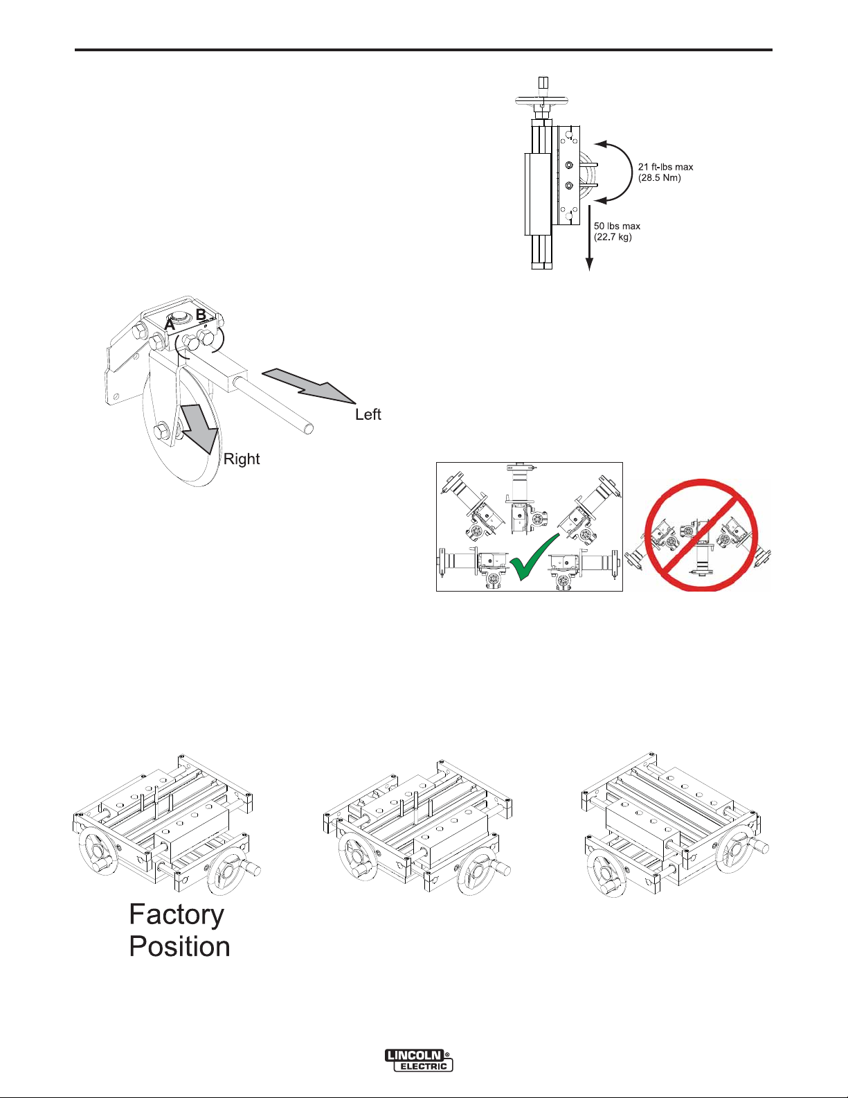
MANUAL STEERING MECHANISM,
ADJUSTMENT
To steer the CRUISER™ to the Right:
Loosen bolt B
Tighten bolt A to set the wheel angle.
Snug bolt B
To steer the CRUISER™ to the Left:
Loosen bolt A
Tighten bolt B to set the wheel angle
Snug bolt A
FIGURE A.8 - ADJUSTMENT
FIGURE A.9 - LOAD LIMITS
WIRE REEL SPINDLE
• Position the wire reel spindle to prevent the reel
and electrode from contacting the tractor frame and
base.
• The wire reel spindle must be horizontal or oriented
upwards.
FIGURE A.11 - WIRE REEL SPINDLE
CROSS SLIDE
Each slide has 4” (102mm) of travel.
When assembling the CRUISER™, verify that no com-
ponents at electrode potential contact the frame
throughout the entire travel distance of the slides.
The slides may be disassembled and then positioned
relative to each other.
FIGURE A.10 - SEVERAL POSSIBLE SLIDE CONFIGURATIONS
CRUISER™
Page 14
A-7
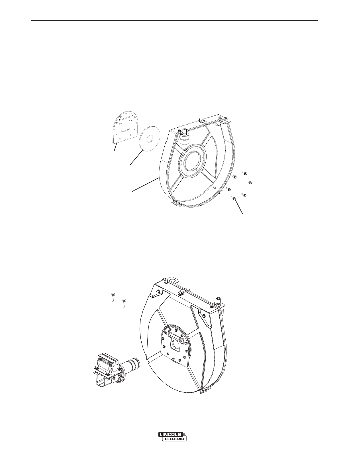
WIRE REEL ENCLOSURE ASSEMBLY
1. Determine the angular orientation of the wire reel
BRACKET
GASKET
INSTALLATION
enclosure relative to the spindle clamp. To change
the angle of the enclosure, remove the 6 bolts
securing the enclosure back to the mounting bracket using a 7/16” wrench. Reassemble at the desire
angle, keep the gasket centered relative to the
enclosure back. Provisions are made to rotate the
enclosure in 30° increments.
FIGURE A.11a - ENCLOSURE ASSEMBLY
A-7
ENCLOSURE
BACK
HARDWARE
2. Unscrew the spindle brake and remove the spindle
brake parts and the spindle.
FIGURE A.11b - ENCLUSURE MOUNTING
3. Remove two of the bolts from the spindle assembly using a 1/4” hex key. Assemble the enclosure
back to the spindle assembly and tighten the bolts.
CRUISER™
Page 15
A-8
INSTALLATION
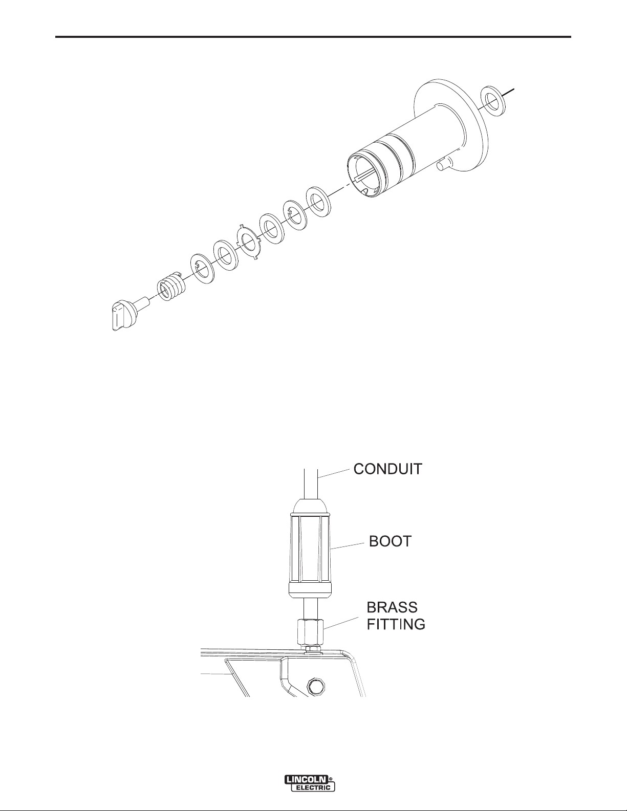
4. Reassemble the spindle parts as shown.
FIGURE A.11c - SPINDLE PARTS
A-8
5. If required, swap the position of the ball bushing
assembly. Use a 7/16” wrench to loosen and
tighten the hardware.
6. Thread the conduit into the brass fitting on the
ball bushing assembly. Then slide the boot along
the conduit and over the brass fitting.
FIGURE A.11d - CONDUIT, BRASS FITTING, BOOT
7. When assembling the enclosure cover to the
enclosure back, verify the cover is evenly seated
all the way around.
CRUISER™
Page 16
A-9
INSTALLATION
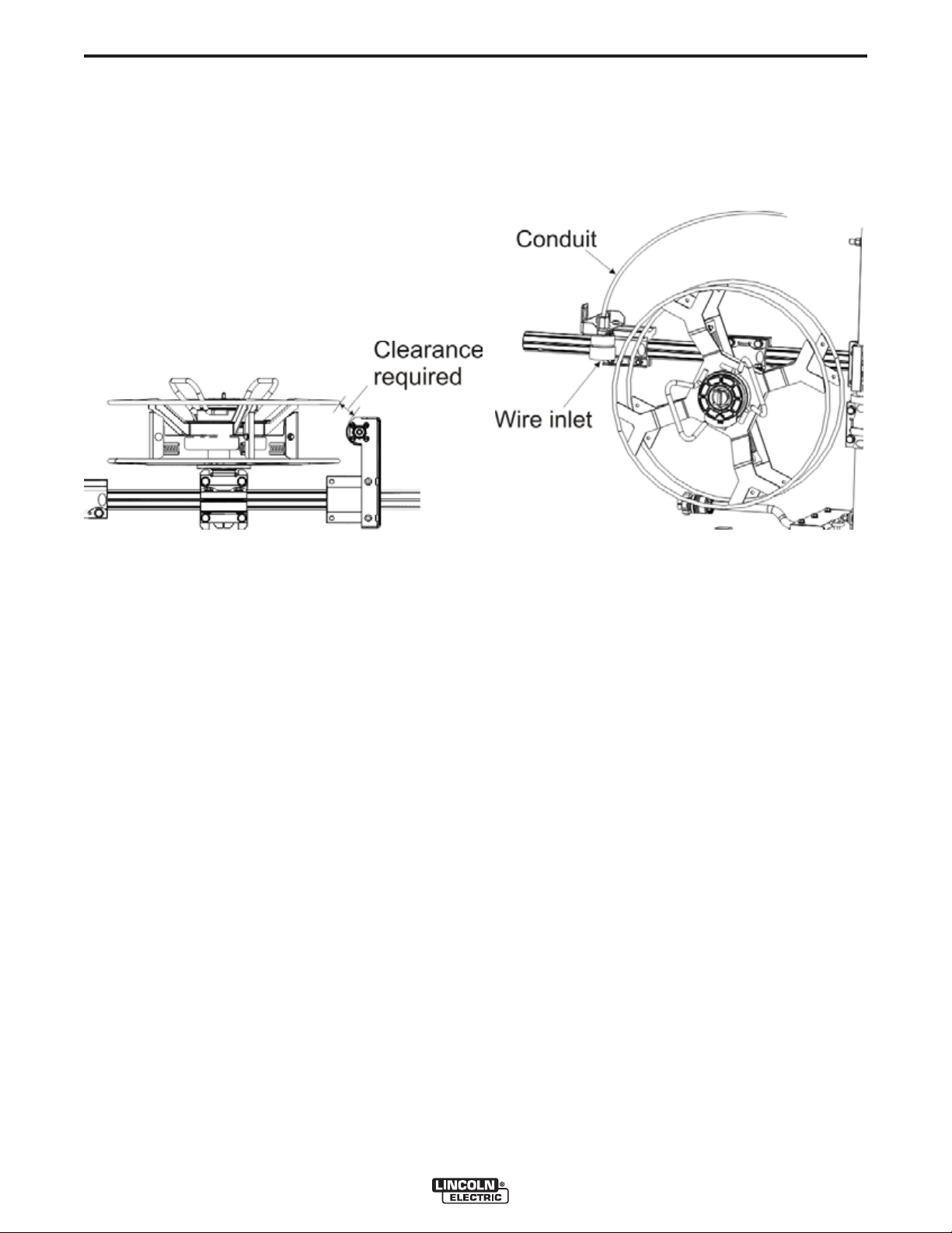
TAKE-OFF ARM
• Position the take off arm to prevent contact to the
reel and electrode.
• Route the electrode through the conduit from the
take off arm to the wire drive.
FIGURE A.12 - TAKE-OFF ARM
A-9
CRUISER™
Page 17
A-10
INSTALLATION
A-10
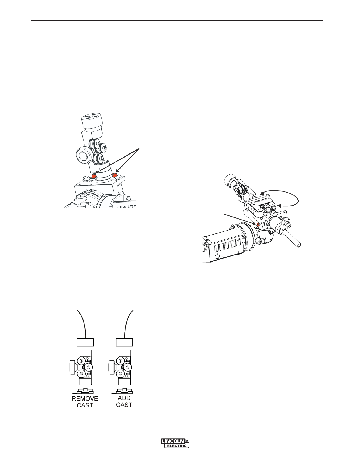
WIRE STRAIGHTENER ADJUSTMENT
The wire straightener controls the amount of cast (or
“curve”) in the wire. Excessive cast may effect alignment of the wire in the joint. Too little cast may result
in insufficient wire contact in the contact tip.
To adjust the wire straightener:
1. Turn off power at the welding power source.
2. Loosen the two screws holding the wire straightener to the feed plate with a ¼” hex key.
FIGURE A.13 - WIRE STRAIGHTENER SCREWS
FEEDPLATE ROTATION
The feedplate of the wire drive may be rotated about
the drive roll axis. Depending upon how the tractor is
assembled, rotating the feed plate will change the tilt
angle or the drag angle.
1. Turn off power at the welding power supply.
2. Loosen the set screw on the feedplate with a 5/16”
hex key.
3. Rotate the feedplate to the new position. Do not
allow surfaces at electrode potential to touch the
frame, flux hopper, base or slides of the tractor.
4. Tighten the set screw to secure the feedplate.
5. As equipped from the factory, the tractor is set-up
with “A” as the inlet and “B” as the outlet. To make
“B” the inlet and “A” the outlet, see the SET-UP
MENU.
FIGURE A.15 - FEEDPLATE ROTATION
3. Position the straightener as desired to remove or
add cast to the wire.
4. Tighten the screws holding the wire straightener to
the feed plate.
5. Turn power on at the welding power source.
6. Feed wire through the straightener. Adjust the
amount of pressure on the wire with the straightener until the desired cast is achieved when the wire
exits the tip.
NOTE: A slight curvature to the wire helps to maintain
good electrical contact inside the contact tip.
FIGURE A.14 - WIRE STRAIGHTENER
CRUISER™
Page 18

A-11
INSTALLATION
A-11
FLUX HOPPER
The flux hopper may be mounted on either a horizontal or vertical tube, or on the wire drive. For the best
flow of flux, keep the hose from the hopper to the nozzle as vertical as possible.
FIGURE A.16 - VERTICAL TUBE MOUNTING
FIGURE A.17 - HORIZONTAL TUBE MOUNTING
CABLES
ArcLink Control Cables
ArcLink Control Cables are available in two forms:
• K1543-xx series for most indoor or factory installations.
• K2683-xx series for outdoor use or when the equipment is frequently moved.
ArcLink/LincNet control cables are special high quality
cables for digital communication. The cables are copper 5 conductor cable in a SO-type rubber jacket.
There is one 20 gauge twisted pair for network communications. This pair has an impedance of approximately 120 ohms and a propagation delay per foot of
less than 2.1 nanoseconds. There are two 12 gauge
conductors that are used to supply 40VDC to the network. The fifth wire is 18 gauge and is used as an electrode sense lead.
Use of non-standard cables may lead to system shutdowns, poor arc starting and wire feeding problems.
The control cables connect the power source to the
wire feeder, and the wire feeder to other wire feeders.
FIGURE A.18 - WIRE DRIVE MOUNTING
Control cables may be connected end to end to extend
their length. Use a maximum of 200 feet (61 m) of control cable between components.
FIGURE A.19 - ARCLINK CONTROL CABLES
E
D
A
C
Pin Function Pin Function
A ArcLink A ArcLink
B ArcLink B ArcLink
C 67 voltage sense C 67 voltage sense
D 40 VDC D 40 VDC
E Common E Common
B
Power Source Wire Feeder
E
D
A
C
B
CRUISER™
Page 19

A-12
CABLE CONNECTIONS
INSTALLATION
FIGURE A.20 - WIRE DRIVE MOUNTING
A-12
WELD CABLE SIZES
Tabulated below are copper cable sizes recommended
for different currents and duty cycles. Lengths stipulated are the distance from the welder to work and back
to the welder again. Cable sizes are increased for
greater lengths primarily for the purpose of minimizing
cable drop.
RECOMMENDED CABLE SIZES (RUBBER COVERED COPPER - RATED 75°C)**
CABLE SIZES FOR COMBINED LENGTHS OF ELECTRODE AND WORK
CABLES
0 to 50 Ft. 50 to 100 Ft. 100 to 150 Ft. 150 to 200 Ft. 200 to 250 Ft.
3/0
2-1/0
2-1/0
3/0
2-1/0
2-2/0
3-1/0
2-3/0
2-4/0
3-3/0
3-4/0
4-4/0
4-4/0
5-4/0
3/0
2-1/0
2-1/0
3/0
2-1/0
2-2/0
3-1/0
2-3/0
2-4/0
3-3/0
3-4/0
4-4/0
4-4/0
5-4/0
Amperes
600
600
600
650
650
700
800
800
1000
1000
1200
1200
1500
1500
Percent
Duty
Cycle
60
80
100
60
80
100
80
100
80
100
80
100
80
100
3/0
2-1/0
2-1/0
4/0
2-1/0
2-3/0
3-1/0
2-3/0
2-4/0
3-3/0
3-4/0
4-4/0
4-4/0
5-4/0
4/0
2-2/0
2-2/0
2-2/0
2-2/0
2-3/0
2-3/0
2-3/0
2-4/0
3-3/0
3-4/0
4-4/0
4-4/0
5-4/0
2-3/0
2-3/0
2-3/0
2-3/0
2-3/0
2-4/0
2-4/0
2-4/0
4-2/0
3-3/0
3-4/0
4-4/0
4-4/0
5-4/0
** Tabled values are for operation at ambient temperatures of 40°C and below. Applications above 40°C may
require cables larger than recommended, or cables rated higher than 75°C.
CRUISER™
Page 20

A-13
SYSTEM SET-UP
INSTALLATION
FIGURE A.21 - SYSTEM SET-UP
A-13
CRUISER™
Page 21

A-14
INSTALLATION
BUTT JOINTS
Butt Joint, Track Welding
• When operating on K396 track, change the wheel
calibration in the SET-UP menu to 5.65”.
FIGURE A.22 - TRACK WELDING FRONT VIEW
A-14
FIGURE A.23 - TRACK WELDING REAR VIEW
FIGURE A.24 - TRACK WELDING TOP VIEW
CRUISER™
Page 22

A-15
INSTALLATION
FIGURE A.25 - BUTT JOINT, 3 WHEEL, MANUAL STEER FRONT VIEW
FIGURE A.26 - BUTT JOINT, 3 WHEEL, MANUAL STEER REAR VIEW
A-15
FIGURE A.27 - BUTT JOINT, 3 WHEEL, MANUAL STEER TOP VIEW
CRUISER™
Page 23

A-16
INSTALLATION
FIGURE A.28 - BUTT JOINT, 3 WHEEL, GUIDE WHEEL, FRONT VIEW
A-16
FIGURE A.29 - BUTT JOINT, 3 WHEEL, GUIDE WHEEL, REAR VIEW
CRUISER™
Page 24

A-17
INSTALLATION
FIGURE A.30 - BUTT JOINT, 3 WHEEL, GUIDE WHEEL, TOP VIEW
A-17
FILLET JOINTS
Horizontal Fillet
Uses KP2721-2 curved nozzle extension (45°).
FIGURE A.31 - HORIZONTAL FILLET, CURVED NOZZLE EXTENTION, FRONT VIEW
CRUISER™
Page 25

A-18
INSTALLATION
FIGURE A.32 - HORIZONTAL FILLET, CURVED NOZZLE EXTENTION, REAR VIEW
A-18
FIGURE A.33 - HORIZONTAL FILLET, CURVED NOZZLE EXTENTION, TOP VIEW
CRUISER™
Page 26

A-19
HORIZONTAL FILLET
Uses KP2721-1 straight nozzle extensions.
FIGURE A.34 - HORIZONTAL FILLET, STRAIGHT NOZZLE EXTENTION, FRONT VIEW
INSTALLATION
A-19
FIGURE A.35 - HORIZONTAL FILLET, STRAIGHT NOZZLE EXTENTION, REAR VIEW
CRUISER™
Page 27

A-20
INSTALLATION
FIGURE A.36 - HORIZONTAL FILLET, STRAIGHT NOZZLE EXTENTION, TOP VIEW
A-20
FIGURE A.37 - HORIZONTAL FILLET TOP VIEW
CRUISER™
Page 28

A-21
FLAT FILLET (TROUGH)
FIGURE A.38 - FLAT FILLET (TROUGH) FRONT VIEW
INSTALLATION
A-21
FIGURE A.39 - FLAT FILLET (TROUGH) REAR VIEW
CRUISER™
Page 29

A-22
INSTALLATION
FLAT FILLET (TROUGH) (CONTINUED)
FIGURE A.40 - FLAT FILLET TOP VIEW
A-22
FIGURE A.41 - FLAT FILLET TOP VIEW
CRUISER™
Page 30

A-23
INSTALLATION
PIPE WELDING
Internal inner diameter welds. The CRUISER™ may
be assembled to fit inside pipes with a 44” (1.1m) inner
diameter.
FIGURE A.42 - PIPE WELDING FRONT VIEW
A-23
FIGURE A.43 - PIPE WELDING REAR VIEW
CRUISER™
Page 31

A-24
PIPE WELDING (CONTINUED)
FIGURE A.44 - PIPE WELDING TOP VIEW
INSTALLATION
A-24
FIGURE A.45 - PIPE WELDING TOP VIEW
CRUISER™
Page 32

A-25
INSTALLATION
BASE DIMENSIONS ONLY
A-25
CRUISER™
Page 33

B-1
OPERATION
B-1
SAFETY PRECAUTIONS, OPERATION
WARNING
ELECTRIC SHOCK can kill.
• Turn the input power OFF at
the disconnect switch before
working on this equipment.
• Do not touch electrically hot
parts.
• Only qualified personnel should install, use or
service this equipment.
• Do not allow parts at electrode potential to touch
the tractor frame, cress slides, base flux hopper
or other parts.
• Disengaging the clutch does not stop the welding arc.
• Always wear dry insulating gloves.
------------------------------------------------------------------------
WARNING
MOVING PARTS can injure.
• Do not leave the tractor unattended while it is welding or
traveling.
• Electrode reel, drive rolls and
wire straightener rolls turn
during welding or inching.
• Keep gloved hands away from rotating parts.
• Keep away from pinch points.
• Do not place the tractor on inclined surfaces with
the clutch disengaged.
• Only qualified personnel should install, use or
service this equipment.
------------------------------------------------------------------------
The serviceability of a product or structure utilizing
the welding programs is and must be the sole
responsibility of the builder / user. Many variables
beyond the control of The Lincoln Electric
Company affect the results obtained in applying
these programs. These variables include, but are
not limited to, welding procedure, plate chemistry
and temperature, weldment design, fabrication
methods and service requirements. The available
range of a welding program may not be suitable for
all applications, and the build / user is and must be
solely responsible for welding program selection.
GRAPHIC SYMBOLS
CRUISER™
Page 34

B-2
OPERATION
FIGURE B.1 - PENDANT CONTROLS
B-2
MOVING THE TRACTOR
The tractor will not travel unless the clutch is engaged.
To engage the clutch, rotate the handle upwards. To
disengage the clutch, rotate the handle to the 3 o’clock
position.
The travel speed is adjustable from 7 to 100 in/min
(1.78 to 2.54 m/min). From 7 to 20 in/min, the travel
speed may be set in 0.5 inch/min increments. Above
20 in/min, the travel speed adjusts at 1.0 inch/min
increments.
To drive the tractor without welding:
FIGURE B.2 - ENGAGE THE CLUTCH
1. Engage the clutch at the rear of the tractor.
FIGURE B.3 - TRAVEL DIRECTION
2. Select either forward or reverse travel on the pen-
dant.
FIGURE B.4 - JOB BUTTON, TOGGLE SWITCH
3. Press and hold the jog button, or place the toggle
switch in the MANUAL travel position.
CRUISER™
Page 35

B-3
OPERATION
B-3
LASER POINTER
CAUTION
• Class II laser radiation present. Do not stare
into laser beam or view directly with optical
instruments.
------------------------------------------------------------------------
Laser pointer is used to aid in guiding the CRUISER™.
The laser pointer mounts to the nozzle or nozzle extensions. Align the wire in the joint, then position the laser
pointer approximately 3” (76mm) in front of the wire,
also pointing into the joint.
Turn the laser off when not welding.
TOUCH SENSE
WARNING
ELECTRIC SHOCK can kill.
• If the Touch Sense is enabled, the
Power Source output is ON as long
as the Feed Forward button is held.
Avoid touching any portion of the
weld circuit while feeding.
------------------------------------------------------------------------
The touch sense option, when enabled, allows the
operator to feed the wire forward until it touches the
workpiece. When contact to the work is made, the wire
will stop.
POWER-UP SEQUENCE
When power is first applied to the CRUISER™ the
MODE SELECT Display reads “CRUISER™
Initializing...”. Once the Power Wave AC/DC has initialized (20 to 60 seconds) a “lamp test” is performed.
• All discrete LED’s, seven segment displays and
alpha numeric displays will be turned ON for 2 seconds.
• After 2 seconds all displays are turned OFF again
and the MSP Display will show:
FIGURE B.5 - MSP DISPLAY
After initialization is complete, the MSP Display will
show the weld mode. The upper displays will show the
parameters that were selected when the machine was
last powered down and the WELD MODE Indicator will
be ON.
FIGURE B.6 - WELD MODE INDICATOR
If the touch sense option is disabled, the wire is “cold”
during the Feed Forward time. It will not stop when it
touches the work.
CRUISER™
Page 36

B-4
OPERATION
B-4
WIRE FEEDER SETUP
WARNING
ELECTRIC SHOCK can kill.
• Prior to inserting the wire, disable “Touch Sense” (P.15 in
the Setup Menu).
------------------------------------------------------------------------
Use the FEED FORWARD pushbutton to insert wire
into the feed mechanism.
While pressing either the FEED FORWARD or FEED
REVERSE pushbutton the MSP Display will read as
shown and the preset wire feed speed will be displayed
on the left (AMPS/WFS) display.
FIGURE B.7 - FEED SPEED DISPLAY
CHANGING AND SETTING WELD MODES
To select a weld mode, press the WELD MODE
SELECTOR button until the WELD MODE indicator
comes ON (it may already be lit by default at power
up). Turn the control knob to select the desired mode.
After about 1 second, the parameters for the new
mode will be displayed. These parameters can be
adjusted with the control knobs below each display.
FIGURE B.9 - SETTING WELD MODES
The feed speed can be changed by adjusting the control knob below the display while pressing either button. Use FEED REVERSE to retract the wire from the
feed mechanism. FEED FORWARD feeds the wire
downward toward the work piece.
The CRUISER™ has an option in the Setup Menu
(P.15) to enable the “Touch Sense” circuitry. See the
Setup Menu. When P.15 is enabled and the FEED
FORWARD button is pressed, the MSP Display will
read:
FIGURE B.8 - HOT FEED FEATURE
WARNING: This “Hot Feed” feature enables the
output of the power source and there is voltage on
the wire while feeding down. Avoid touching any
exposed parts as defined in the SAFETY PRECAU-
TIONS.
NOTE: CC Modes will show AMPS in the upper left
display. CV Modes will show wire feed speed
and the WFS indicator will be lit.
FREQUENCY
Press the WELD MODE selector until the FREQUENCY/ BALANCE indicator comes ON and the MSP
Display reads “Frequency”. If the selected mode allows
for frequency adjustment, the Control Knob can be
used to select the desired frequency between 10 and
100hz.
FIGURE B.10 - FREQUENCY
Use Frequence to fine tune stability of imbalance
1000
waveforms and multiple arc systems
600
0
- 600
- 1000
Decrease
Frequency adjustment can be used to fine tune stability of imbalanced waveforms and multiple arc system.
Increase
CRUISER™
Page 37

B-5
OPERATION
B-5
BALANCE ADJUST
Press the WELD MODE selector until the MSP Display
reads “Balance”. If the selected mode allows for balance adjustment, the Control Knob can be used to
select the desired wave balance through a range of
25% to 75%.
FIGURE B.11 - BALANCE ADJUST
1000
Nominal Balance
500
0
-500
-1000
Increased Balance
More Penetration
Less Deposition
Decreased Balance
Less Penetration
More Deposition
Adjusting the Balance (the ratio between Positive and
Negative half cycle ‘on time’) changes the deposition
for more efficient welding.
OFFSET ADJUST
Press the WELD MODE selector until the MSP Display
reads “Offset”. If the selected mode allows for offset
adjustment, the Control Knob can be used to select the
desired offset. The amount of offset allowed is determined by the selected weld mode.
Independent control of the Positive and Negative
cycles allows for more precise control of penetration
and deposition.
FIGURE B.12 - OFFSET ADJUST
WELD SEQUENCE
The weld sequence defines the weld procedure from
beginning to end. All adjustments are made through
the user interface.
FIGURE B.13 - WELD SEQUENCE
START OPTIONS
The delay, strike, start and upslope parameters are
used at the beginning of the weld sequence to establish a stable arc and provide a smooth transition to the
welding parameters. They are described in the following:
• ARC DELAY inhibits the wire feed for up to 5 sec-
onds to provide an accurate weld start point.
Typically used in multi-arc systems.
• STRIKE settings are valid from the beginning of the
sequence (Start) until the arc is established. They
control run-in (speed at which the wire approaches
the workpiece) and provide the power to establish
the arc. Typically output levels are increased, and
WFS is reduced during the strike portion of the weld
sequence.
1000
500
0
-500
-1000
Nominal Offset
Positive Offset
More Penetration
Less Deposition
Negative Offset
Less Penetration
More Deposition
• START values allow the arc to become stabilized
once it is established. Extended start times or
improperly set parameters can result in poor starting.
• UPSLOPE TIME determines the amount of time it
takes to ramp from the start parameters to the weld
parameters. The transition is linear and may be up or
down depending on the relationship between the
start and weld settings.
CRUISER™
Page 38

B-6
OPERATION
START OPTIONS OPERATION
Pressing the Arc Start/End Options pushbutton will
illuminate the START OPTIONS LED and the Arc
Delay Time parameter will show on the MSP Display.
FIGURE B.14 - START OPTIONS OPERATION
Use the Mode Select Panel Control to select the
desired delay time. Press the Weld Mode Selector to
exit the Start parameters. Repeated pressing of the
Arc Start/End Options pushbutton will scroll through
the parameters. Turning the Mode Select Panel
Control, while on a parameter will change its value.
When a Start Option is set to a value other than OFF,
the START OPTIONS LED will blink synchronous with
the WFS or Amps and/or the Volts LED located on the
Dual Display Panel prompting the user to enter these
parameters. The parameters that can be set by the
user in the START OPTIONS will be as follows:
B-6
• RESTRIKE TIME determines how long the system
will try to re-establish the arc in the event of a poor
start or if the arc goes out for any reason (short circuit or open circuit). During restrike, the WFS and
outputs are driven in an attempt to re-establish the
arc.
• A restrike time of 1 to 2 seconds is sufficient
in most applications.
• A restrike time of 0 seconds allows the
restrike function to continue indefinitely.
END OPTIONS OPERATION
Pressing the Arc Start/End Options pushbutton after
scrolling through the Start Options will illuminate the
END OPTIONS LED and the Downslope Time parameter will show on the MSP Display.
FIGURE B.15 - END OPTIONS OPERATION
ARC DELAY TIME
STRIKE WFS
STRIKE TIME
START WFS/AMPS
START VOLTS
START TIME
UPSLOPE TIME
END OPTIONS
The downslope, crater, and burnback parameters are
used to define the end of the weld sequence. They are
defined in the following:
• DOWNSLOPE determines the amount of time it
takes to ramp from the weld parameters to the crater
parameters. The transition is linear and may be up or
down depending on the relationship between the
weld and crater settings.
• CRATER parameters are typically used to fill the
crater at the end of the weld and include both time
and output settings.
• BURNBACK defines the amount of time the output
remains on after the wire has stopped. This feature
is used to prevent the wire from sticking in the weld
puddle and to condition the end of the wire for the
next weld. A burnback time of 0.4 second is sufficient
in most applications.
Use the Mode Select Panel Control to select the
desired delay time. Press the Weld Mode Selector to
exit the End parameters. Repeated pressing of the Arc
Start/End Options pushbutton will toggle through the
parameters. Turning the Mode Select Panel Control
while on a parameter will change its value. When the
Crater Time is set to a value other than OFF, the END
OPTIONS LED will blink synchronous with the WFS or
Amps LED (depending on CC or CV Weld Modes) and
with the Volts LED located on the Dual Display Panel
prompting the user to enter these parameters. The
parameters that can be set by the user in the END
OPTIONS will be as follows:
DOWNSLOPE TIME
CRATER WFS/AMPS
CRATER VOLTS
CRATER TIME
BURNBACK TIME
RESTRIKE TIME
CRUISER™
Page 39

B-7
MEMORIES
OPERATION
B-7
The CRUISER™ has 4 memories. Each memory
stores :
• Weld Mode
• Amperage (or WFS)
• Voltage
• Travel Speed
• Frequency
• Balance
• DC Offset
• Arc Start Options
• Arc End Options
FIGURE B.16 - MEMORIES
LIMITS
Limits allow the welder to adjust the welding procedure
only within a defined range.
Each memory may have a different set of limits. For
example, memory 1 may limit the WFS to 100 through
120 in/min, and memory 2 may limit the WFS to 140
through 160 in/min, while memory 3 may have no WFS
limits.
Parameters are constrained by machine limits, or by
setting memory limits. When memory limits are
enabled, the parameter will flash whenever an attempt
FIGURE B.17 - LIMITS
Recall a memory with memory buttons
To recall a memory, press one of the four memory buttons. The memory is recalled when the button is
released. Do not hold the button for more than two seconds.
Save a memory with memory buttons
To save a memory, press and hold the desired memory button for two seconds. When the button is initially
pressed, the corresponding LED will illuminate. After
two seconds, the LED will turn off. Do not hold the button for more than 5 seconds when saving a user memory.
Note that memories may be locked in the set-up menu
to prevent accidental overwrite of the memories. If an
attempt is made to save a memory when memory saving is locked, the message "Memory save is Disabled!"
will appear briefly in the MSP4 display.
is made to exceed the memory limit value. The parameter will not flash if an attempt is made to exceed the
machine limit.
Limits may be set for:
Wire Feed Speed
Voltage
Amperage
Travel Speed
Frequency
Balance
DC Offset
Arc Start Options
Arc End Options
Weld modes cannot be selected through the Limits
Setup menu, and must be chosen and saved to memory before entering the Limits Setup Menu.
CRUISER™
Page 40

B-8
Y
OPERATION
To set limits, press the desired memory button 1-8 and
hold for 5 seconds. Release the memory button when
the LED begins to blink rapidly and the MSP4 displays
"Memory X Set Limits" as shown below.
FIGURE B.18 - MEMORY SET LIMITS
FIGURE B.19 - MEMORY SET LIMIT DISPLAY
HIGH
LIMIT
MEMO R
VALUE
LOW
LIMIT
B-8
The Limits Setup menu shows a list of all parameters
available for the weld mode stored in the memory chosen
To lock a parameter to a specific value that cannot
be changed, set the high and low limits to the same
value.
The memory value must always be less than or equal
to the high limit, and greater than or equal to the low
limit.
After setting limits, press the memory button with the
flashing LED. The MSP4 will ask to save or discard the
limit changes just made. Press the left MSP4 for button
(YES) to save and enable the limits and exit. Press the
right MSP4 button (NO) to exit and leave limits
unchanged.
ENABLING/DISABLING LIMITS
FIGURE B.21 - ENABLING LIMITS
PARAMET ER
NAME
SETUP will illuminate on the MSP4 panel and the display will show the following:
Four items show on the MSP4 panel.
• Memory Value
• High Limit
• Low Limit
• Parameter Name
One of these items will flash to indicate which item will
change when the MSP4 encoder is rotated. Press the
right button on the MSP4 panel to select the item to
change.
FIGURE B.20 - MSP4 PANEL
Limits for each memory may be enabled or disabled by
pressing and holding the appropriate memory button
for 10 seconds. Release the memory button when the
MSP4 display shows the following:
FIGURE B.22 - ENABLE/DISABLE LIMITS
CRUISER™
Page 41

B-9
OPERATION
B-9
SETUP will light and the MSP4 displays the following:
FIGURE B.23 - ENABLE/DISABLE LIMITS
DISPLAY
Press the left MSP4 button (YES) to enable limits or
the right MSP4 button (NO) to disable limits. Disabling
limits does not change any limits values that may have
been previously set.
DIP SWITCHES
The DIP switches on the pc boards are set at the factory and do not require adjustment.
Travel Board DIP Switches Wire Drive Board DIP Switches
All the DIP switches are in the OFF position. All the DIP switches are in the OFF position.
ON
OFF
1 2 3 4 5 6 7 8
8 7 6 5 4 3 2 1
OFF
ON
CRUISER™
Page 42

B-10
OPERATION
B-10
SET-UP FEATURES MENU
The Setup Menu gives access to the set-up configuration. Stored in the set-up configuration are user parameters
that generally need to be set only at installation. The parameters are grouped as follows:
PARAMETER
P.1 through P.99
P.101 through P.199
P.501 through P.599
To access the set-up menu, press the right and left buttons of the MSP4 panel simultaneously. Note that the setup menu cannot be accessed if the system is welding, or if there is a fault (The status LED is not solid green).
Change the value of the blinking parameter by rotating the SET knob.
To exit the set-up menu at any time, press the right and left buttons of the MSP4 panel simultaneously. Alternately,
1 minute of inactivity will also exit the set-up menu.
Secured Parameters (only accessible with Weld Manager)
Unsecured Parameters (always adjustable)
Diagnostic Parameters (always read only)
DEFINITION
PARAMETER DEFINITION
P.0
P.1
P.2
P.3
Press the left button to exit the set-up menu.
WFS units
Metric = m/min wire feed speed units
English = in/min wire feed speed units (default)
Arc Display Mode
Amps = The left display shows Amperage while welding. (default)
WFS = The left display shows Wire Feed Speed while welding.
Display Options
This setup parameter was previously named "Display Energy"
P.12
If the previous software revision had this parameter set to display energy, that selection will
remain.
This option selects the information displayed on the alphanumeric displays while welding. Not
all P.3 selections will be available on all machines. In order for each selection to be included
in the list, the power source must support that feature. A software update of the power source
may be needed to include the features.
Standard Display = The lower displays will continue to show preset information during and
after a weld (default).
Show Energy = Energy is displayed, along with time in HH:MM:SS format.
Show Weld Score = The accumulative weld score result is shown.
Travel Options
This menu is used to change the travel options for a travel carriage, including wheel size and
starting and ending functions. Press the right MSP4 button to enter the Travel Options menu
and rotate the encoder to select either wheel size, starting or ending options. Press the right
MSP4 button to select the option. Press the left MSP4 button to set the value and exit. Rotate
the encoder to select other options, or press the left MSP4 button to exit the menu.
Travel Start Options
Start Button = Travel begins with the start button (default)
Arc Strike = Travel beings with arc strike.
Travel End Options
Stop Button = Travel ends with the stop button. (default)
Arc Out = Travel ends when the arc extinguishes.
Wheel Size
default value = 6.0”
wheel size for track welding = 5.65”
range = 3.0” to 12.0”
CRUISER™
Page 43

B-11
OPERATION
PARAMETER DEFINITION
B-11
P.14
P.15
P.18
P.19
P.21
Reset Consumable Weight
This parameter only appears with systems using Production Monitoring.
Use this parameter to reset the initial weight of the consumable package.
Cold-Inch Touch Sense Option
Enabled = touch sense is active when inching wire forward.
Disabled = touch sense is inactive when inching wire forward. (default)
Wire Drive Gear Ratio.
Set this parameter to match the gear ratio of the wire drive.
142:1 (default)
95:1
57:1
Wire Drive Direction
The feed plate of the wire drive is reversible and the wire straightener and
the nozzle assembly may be swapped. The feed plate can feed from A
(inlet ) to B (outlet); or B (inlet) to A (outlet).
Set this parameter to match the “Forward” direction of wire feeding.
A → B (Default)
B → A
Shutdown 2 Function Select
This option allows selection of the Shutdown 2 input function on the control
box.
Normal Shutdown = The Shutdown 2 input functions as a standard shutdown input that locks out all input buttons (default)
Output Disable = The Shutdown 2 input functions as a machine output
lockout to disable the welding circuit but still allow cold feeding of the wire.
P.23
P.80
P.99
Trigger Fan-Out
For Sub-Arc Lead Arc machines only. Allows the Lead Arc User Interface
to control all machine triggers in a multi-arc system.
No = Only the machine connected to the User Interface can be triggered on
and off (default).
Yes = All machines in the system can be triggered on and off simultaneously.
Sense from Studs.
Use this parameter for diagnostic purposes only. When power is cycled,
P.80 is automatically reset to False.
False = Sensing for the electrode (67) and work (21) is determined by the
DIP switches of the system.
True = Sensing for the electrode (67) and work (21) is measured at the
studs of the power source and the DIP switch settings are overridden.
Show Test Modes
Many weld tables include special modes for testing and servicing the welding system. Set this parameter to YES to show all test modes.
When the power source is turned off, the Show Test Modes parameter
automatically reverts back to “NO”.
CRUISER™
Page 44

B-12
OPERATION
PARAMETER DEFINITION
B-12
P.100
P.101
P.102
P.103
P.104
View Diagnostics
Diagnostics are only used for servicing the Power Wave system.
Yes = Shows P.101 through P.500 in the SETUP menu.
No = Only P.0 through P.100 are shown in the SETUP menu.
Event Logs
Press the right MSP4 button to view the Event Logs. Rotate the encoder to
select the object to read and then press the right MSP4 button. Various
software information will appear about key system events.
Press the left MSP4 button to exit.
Fatal Logs
Press the right MSP4 button to view the Fatal Logs. Rotate the encoder to
select the module to read and then press the right MSP4 button. Various
software information will appear about critical module actions.
Press the left MSP4 button to exit.
Software Version
Press the right MSP4 button to view the software loaded into each module
(p.c. board). Rotate the encoder to select the module to read and then
press the right MSP4 button. The panel will display the main software version loaded into the module. Press the left MSP4 button to exit.
Hardware Version
Press the right MSP4 button to view the hardware version of each module
(p.c. board). Rotate the encoder to select the module to read and then
press the right MSP4 button. The panel will display the main hardware version loaded into the module. Press the left MSP4 button to exit.
P.105
P.106
P.107
P.500
Welding Software
Press the right MSP4 button to view the welding software version inside the
power source. Press the left MSP4 button to exit.
Ethernet IP Address
Press the right MSP4 button to view the IP address of the Ethernet board.
If no Ethernet Board is installed, the display shows “No Enet Found.” Press
the left MSP4 button to exit.
Power Source
Press the right MSP4 button to view the type of power source connected to
the control box. Press the left MSP4 button to exit.
Parameters that are P.500 and higher are only accessible with Weld
Manager. See Weld Manager documentation for details.
CRUISER™
Page 45

C-1
ACCESSORIES
OPTIONAL KITS AND ACCESSORIES
DRIVE ROLL AND GUIDE TUBE KITS
ITEM K# DESCRIPTION
1 K1733-5 Wire Straightener
KP1899-1 Drive Roll/ Guide Tube Kit, 3/32-7/32
2 KP1899-2 Drive Roll/ Guide Tube Kit, 1/16, 5/64, 3/32
KP1899-3 Drive Roll/ Guide Tube Kit, 035, 045, 052
KP1899-4 Drive Roll/ Guide Tube Kit, 045, 052 cored
K231-5/64 Contact Nozzle Assembly, 5/64 (2.0mm)
K231-3/32 Contact Nozzle Assembly, 3/32 (2.4mm)
3 K231-1/8 Contact Nozzle Assembly, 1/8 (3.2mm)
K231-5/32 Contact Nozzle Assembly, 5/32 (4.0mm)
K231-3/16 Contact Nozzle Assembly, 3/16 (4.8mm)
K231-7/32 Contact Nozzle Assembly, 7/32 (5.6mm)
4 KP2721-1 Nozzle Extension, 5”
KP2721-2 Nozzle Extension, 45º Curved
T12929 Flux Hose Clamp
T11807 Nozzle Extension Insulator
KP1962-3B1 Contact Tip, 3/32
KP1962-1B1 Contact Tip, 1/8
5 KP1962-4B1 Contact Tip, 5/32
KP1962-2B1 Contact Tip, 3/16
KP1962-5B1 Contact Tip, 7/32
K148A or Positive Contact Nozzle Assembly
K148B
K285 Concentric Flux Cone Assembly to use with
K148A or K148B
C-1
1
2
3
K231 nozzles are rated up to 600 Amps
K148 nozzles are rated up to 1000 Amps
4
5
CRUISER™
Page 46

C-2
ACCESSORIES
C-2
K3090-1 Tube and clamp kit Includes: one 30”
aluminum splined tube;
one 15” aluminum splined
tube; one 30” steel tube; 8
clamp assemblies with
keys; 2 outrigger
assemblies; hardware.
K3089-1 Cross Slide Assembly Includes: two slides with 4
inches of travel. (1 cross
slide assembly included
with each tractor.)
K1733-5 Wire Straightener Includes: A three roll wire
straightener with
adjustable pressure. (1
included with each tractor)
K396 Track Section Includes: a single section
of 70 in (1.8m) of track.
K3070-1 Tiny Twin Kit for the
K1543-xx ArcLink Control Cable Includes: 5 pin to 5 pin
K2683-xx ArcLink Control Cable,
K1504-1 60 lb Coil Adapter Includes: one coil adapter
tractor
Heavy Duty
Includes: 2
rolls, 57:1 gears.
tractor to power source
control cable. Cables may
be connected end-to-end to
make a longer cable.
Connectors are black
anodized aluminum.
Includes: 5 pin to 5 pin
tractor to power source
control cable. Cables may
be connected end-to-end to
make a longer cable.
Female connector is a
brass spin nut. Male
connector is made from
stainless.
for use with 2” spindles.
nd
spindle, drive
Accessories Included with the CRUISER™:
Conduit Tubing, 5 feet (1.5 m)
5/32” 600 Amp contact nozzle assembly
5/32” contact tip
Nozzle extension, 5 inches long (127 mm)
Nozzle extension insulator
Nozzle extension, 45° Curved
Flux tubing
Flux Hose Clamps
Wire Reel Assembly
Wheels for track operation
Manually guide steering wheel (LT-7 like)
Front and Rear outriggers
Wire Reel Enclosure
Does not include a control cable.
CRUISER™
Page 47

D-1
ROUTINE MAINTENANCE
Blow out the slides
PERIODIC MAINTENANCE
Check wire drive motor brushes
Lube gearbox for wire drive
MAINTENANCE
D-1
CRUISER™
Page 48

E-1
TROUBLESHOOTING
HOW TO USE TROUBLESHOOTING GUIDE
WARNING
Service and Repair should only be performed by Lincoln Electric Factory Trained Personnel.
Unauthorized repairs performed on this equipment may result in danger to the technician and
machine operator and will invalidate your factory warranty. For your safety and to avoid Electrical
Shock, please observe all safety notes and precautions detailed throughout this manual.
__________________________________________________________________________
E-1
This Troubleshooting Guide is provided to help you
locate and repair possible machine malfunctions.
Simply follow the three-step procedure listed below.
Step 1. LOCATE PROBLEM (SYMPTOM).
Look under the column labeled “PROBLEM (SYMPTOMS)”. This column describes possible symptoms
that the machine may exhibit. Find the listing that
best describes the symptom that the machine is
exhibiting.
Step 2. POSSIBLE CAUSE.
The second column labeled “POSSIBLE CAUSE” lists
the obvious external possibilities that may contribute
to the machine symptom.
Step 3. RECOMMENDED COURSE OF ACTION
This column provides a course of action for the
Possible Cause, generally it states to contact your
local Lincoln Authorized Field Service Facility.
If you do not understand or are unable to perform the
Recommended Course of Action safely, contact your
local Lincoln Authorized Field Service Facility.
CAUTION
If for any reason you do not understand the test procedures or are unable to perform the tests/repairs safely, contact your Local
Lincoln Authorized Field Service Facility for technical troubleshooting assistance before you proceed.
CRUISER™
Page 49

E-2
Observe all Safety Guidelines detailed throughout this manual
PROBLEMS
(SYMPTOMS)
TROUBLESHOOTING
POSSIBLE
CAUSE
E-2
RECOMMENDED
COURSE OF ACTION
A wire drive motor overload occurs.
(Error 81)
A travel motor overload occurs.
(Error 81)
1. Examine the contact tip for wear
and proper size. Replace as
necessary.
2. Verify the correct drive rolls and
inner wire guide are installed in
the wire drive.
3. Do not use more idle roll pressure than necessary. Check for
proper setting.
4. Verify that the wire pulls easily
through the take-off arm bushing
and conduit.
5. Check that the wire straightener
is not exerting excessive load on
the wire.
6. If using 57:1 gear ratio, switch to
95:1 or 142:1
7. If using 95:1 gear ratio, switch to
142:1.
1. Verify the Cruiser rolls freely
when the clutch is disengaged.
2. Check for excessive loads
caused by dragging long cables.
3. When using the outriggers to
steer the Cruiser, set the offset
between the front and rear outriggers at 0.5” (12.7mm).
4. Verify the front wheels are perfectly straight.
If all recommended possible areas
of misadjustment have been
checked and the problem persists,
Contact your local Lincoln
Authorized Field Service Facility.
Error 215
Frequency and Balance do not
appear on the display.
The wire feeder does not feed wire
and the drive rolls do not spin.
1. Check that all of the DIP switches on the travel drive board and
the wire drive board are in the
OFF position.
1. Verify a AC square wave weld
mode has been selected.
1. Verify the power source is
turned on.
2. Verify the circuit breaker for the
wire feeder power (on the power
source) has not tripped.
3. Verify power is being supplied
to the wire feeder.
4. Check that any equipment connected to the external shut-off
inputs has not faulted.
CAUTION
If for any reason you do not understand the test procedures or are unable to perform the tests/repairs safely, contact your Local
Lincoln Authorized Field Service Facility for technical troubleshooting assistance before you proceed.
CRUISER™
Page 50

E-3
Observe all Safety Guidelines detailed throughout this manual
PROBLEMS
(SYMPTOMS)
TROUBLESHOOTING
POSSIBLE AREAS OF
MISADJUSTMENTS(S)
E-3
RECOMMENDED
COURSE OF ACTION
The wire drive feeds wire in the
wrong direction.
The wire drive speed is incorrect.
When the welding arc is activated,
the drive rolls spin but no arc is present.
The Cruiser welds for a short period, then the arc goes out, the wire
stops, travel continues, and no
error codes are displayed on the
pendant.
The arc goes to full output.
1. Change P19 wire feed direction
parameter in the Set-Up menu.
1. Verify the gear ratio of the wire
drive and P18 match.
1. Check all electrode and work
connections.
1. Check for loose or damaged
work and electrode sense leads.
1. Verify work sense lead is making
a good connection and there is
no damage to the lead.
2. Check the electrode sense lead
at the Cruiser and make sure it is
a good connection.
If all recommended possible areas
of misadjustment have been
checked and the problem persists,
Contact your local Lincoln
Authorized Field Service Facility.
CAUTION
If for any reason you do not understand the test procedures or are unable to perform the tests/repairs safely, contact your Local
Lincoln Authorized Field Service Facility for technical troubleshooting assistance before you proceed.
CRUISER™
Page 51

F-1
ENHANCED DIAGRAM
WIRING DIAGRAM
F-1
CRUISER™
NOTE: This diagram is for reference only. It may not be accurate for all machines covered by this manual. The specific diagram for a particular code is pasted inside the
machine on one of the enclosure panels. If the diagram is illegible, write to the Service Department for a replacement. Give the equipment code number.
Page 52

WARNING
Spanish
AVISO DE
PRECAUCION
Do not touch electrically live parts or
electrode with skin or wet clothing.
Insulate yourself from work and
ground.
No toque las partes o los electrodos
bajo carga con la piel o ropa mojada.
Aislese del trabajo y de la tierra.
Keep flammable materials away.
Mantenga el material combustible
fuera del área de trabajo.
Wear eye, ear and body protection.
Protéjase los ojos, los oídos y el
cuerpo.
French
ATTENTION
German
WARNUNG
Portuguese
ATENÇÃO
Japanese
Chinese
Korean
Arabic
Ne laissez ni la peau ni des vête-
ments mouillés entrer en contact
avec des pièces sous tension.
Isolez-vous du travail et de la terre.
Berühren Sie keine stromführenden
Teile oder Elektroden mit Ihrem
Körper oder feuchter Kleidung!
Isolieren Sie sich von den
Elektroden und dem Erdboden!
Não toque partes elétricas e elec-
trodos com a pele ou roupa molhada.
Isole-se da peça e terra.
Gardez à l’écart de tout matériel
inflammable.
Entfernen Sie brennbarres Material!
Mantenha inflamáveis bem guarda-
dos.
Protégez vos yeux, vos oreilles et
votre corps.
Tragen Sie Augen-, Ohren- und Kör-
perschutz!
Use proteção para a vista, ouvido e
corpo.
READ AND UNDERSTAND THE MANUFACTURER’S INSTRUCTION FOR THIS EQUIPMENT AND THE CONSUMABLES TO BE
USED AND FOLLOW YOUR EMPLOYER’S SAFETY PRACTICES.
SE RECOMIENDA LEER Y ENTENDER LAS INSTRUCCIONES DEL FABRICANTE PARA EL USO DE ESTE EQUIPO Y LOS
CONSUMIBLES QUE VA A UTILIZAR, SIGA LAS MEDIDAS DE SEGURIDAD DE SU SUPERVISOR.
LISEZ ET COMPRENEZ LES INSTRUCTIONS DU FABRICANT EN CE QUI REGARDE CET EQUIPMENT ET LES PRODUITS A
ETRE EMPLOYES ET SUIVEZ LES PROCEDURES DE SECURITE DE VOTRE EMPLOYEUR.
LESEN SIE UND BEFOLGEN SIE DIE BETRIEBSANLEITUNG DER ANLAGE UND DEN ELEKTRODENEINSATZ DES HERSTELLERS. DIE UNFALLVERHÜTUNGSVORSCHRIFTEN DES ARBEITGEBERS SIND EBENFALLS ZU BEACHTEN.
Page 53

Keep your head out of fumes.
Use ventilation or exhaust to
remove fumes from breathing zone.
Turn power off before servicing.
Do not operate with panel open or
guards off.
WARNING
Los humos fuera de la zona de res-
piración.
Mantenga la cabeza fuera de los
humos. Utilice ventilación o
aspiración para gases.
Gardez la tête à l’écart des fumées.
Utilisez un ventilateur ou un aspira-
teur pour ôter les fumées des zones
de travail.
Vermeiden Sie das Einatmen von
Schweibrauch!
Sorgen Sie für gute Be- und
Entlüftung des Arbeitsplatzes!
Mantenha seu rosto da fumaça.
Use ventilação e exhaustão para
remover fumo da zona respiratória.
Desconectar el cable de ali-
mentación de poder de la máquina
antes de iniciar cualquier servicio.
Débranchez le courant avant l’entre-
tien.
Strom vor Wartungsarbeiten
abschalten! (Netzstrom völlig öffnen; Maschine anhalten!)
Não opere com as tampas removidas.
Desligue a corrente antes de fazer
serviço.
Não toque as partes elétricas nuas.
No operar con panel abierto o
guardas quitadas.
N’opérez pas avec les panneaux
ouverts ou avec les dispositifs de
protection enlevés.
Anlage nie ohne Schutzgehäuse
oder Innenschutzverkleidung in
Betrieb setzen!
Mantenha-se afastado das partes
moventes.
Não opere com os paineis abertos
ou guardas removidas.
Spanish
AVISO DE
PRECAUCION
French
ATTENTION
German
WARNUNG
Portuguese
ATENÇÃO
Japanese
Chinese
Korean
Arabic
LEIA E COMPREENDA AS INSTRUÇÕES DO FABRICANTE PARA ESTE EQUIPAMENTO E AS PARTES DE USO, E SIGA AS
PRÁTICAS DE SEGURANÇA DO EMPREGADOR.
Page 54

• World's Leader in Welding and Cutting Products •
• Sales and Service through Subsidiaries and Distributors Worldwide •
Cleveland, Ohio 44117-1199 U.S.A. TEL: 216.481.8100 FAX: 216.486.1751 WEB SITE: www.lincolnelectric.com
 Loading...