

Page 1

Operator’s Manual
RETURN TO MAIN MENU
POWER FEED ™25M
For use with machines having Code Numbers:
11743, 11744
Save for future reference
Date Purchased
Code: (ex: 10859)
Serial: (ex: U1060512345)
IM10077 | Issue D ate Oct- 13
© Lincoln Global, Inc. All Rights Reserved.
Register your machine:
www.lincolnelectric.com/register
Authorized Service and Distributor Locator:
www.lincolnelectric.com/locator
Page 2
THANK YOU FOR SELECTING
AT ALL
TIMES.
SPECIAL SITUATIONS
Additional precautionary measures
A QUALITY PRODUCT BY
LINCOLN ELEC TRIC.
PLEASE EXAMINE CARTON AND EQUIPMENT FOR
DAMAGE IMMEDIATELY
When this equipment is shipped, title passes to the purchaser upon
receipt by the carrier. Consequently, Claims for material damaged in
shipment must be made by the purchaser against the transportation
company at the time the shipment is received.
SAFETY DEPENDS ON YOU
Lincoln arc welding and cutting equipment is designed and built with
safety in mind. However, your overall safety can be increased by
proper installation ... and thoughtful operation on your part.
DO NOT INSTALL, OPERATE OR REPAIR THIS EQUIPMENT
WITHOUT READING THIS MANUAL AND THE SAFETY PRECAUTIONS
CONTAINED THROUGHOUT. And, most importantly, think before you
act and be careful.
WARNING
This statement appears where the information must be followed
exactly to avoid serious personal injury or loss of life.
CAUTION
This statement appears where the information must be followed to
avoid minor personal injury or damage to this equipment.
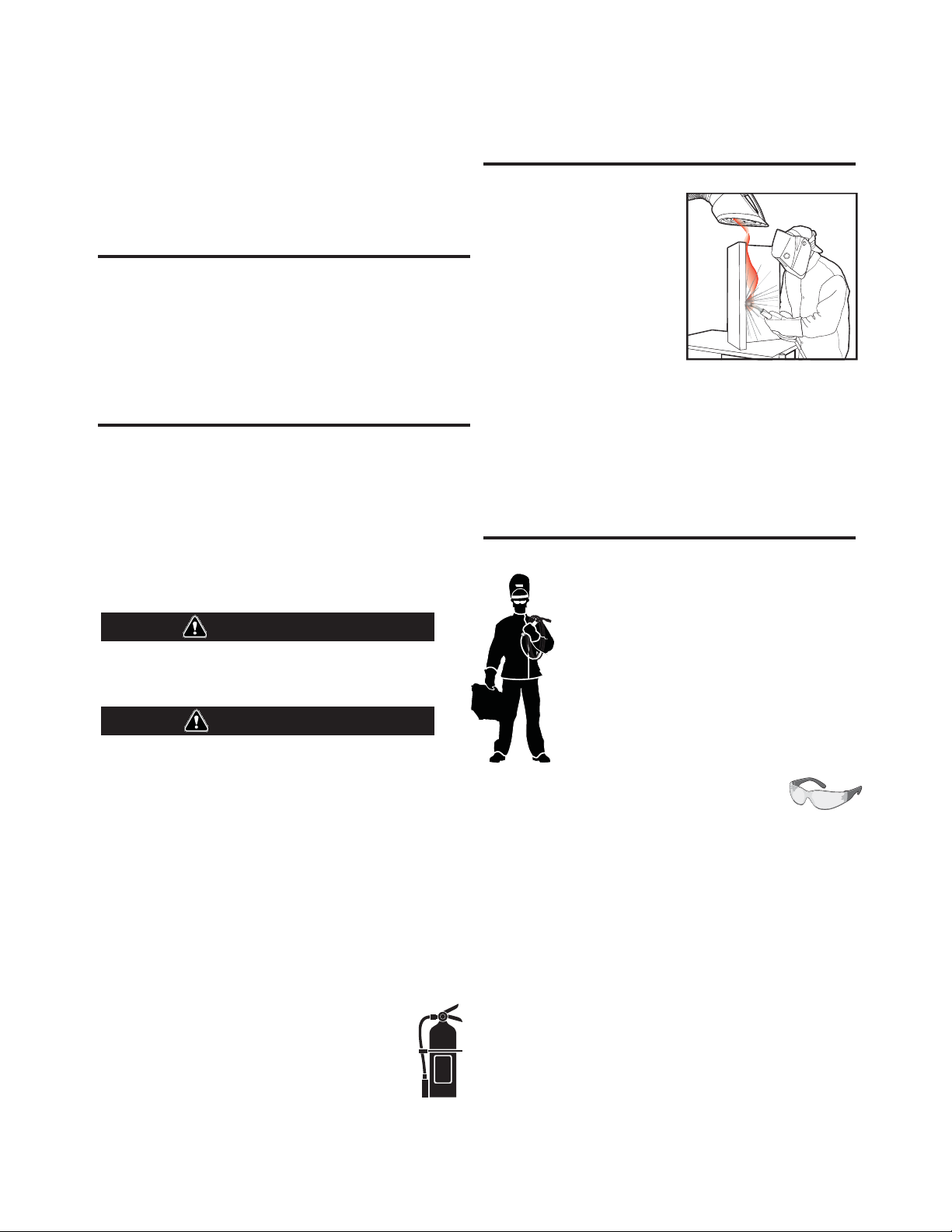
KEEP YOUR HEAD OUT OF THE FUMES.
DON’T get too close to the arc. Use
corrective lenses if necessary to
stay a reasonable distance away
from the arc.
READ and obey the Material Safety
Data Sheet (MSDS) and the warning
label that appears on all containers
of welding materials.
USE ENOUGH VENTILATION or
exhaust at the arc, or both, to keep
the fumes and gases from your breathing zone and the general area.
IN A LARGE ROOM OR OUTDOORS, natural ventilation may be
adequate if you keep your head out of the fumes (See below).
USE NATURAL DRAFTS or fans to keep the fumes away from your
face.
If you de velop unusual symptoms, see your supervisor. Perhaps the
welding atmosphere and ventilation system should be checked.
WEAR CORRECT EYE, EAR & BODY PROTECTION
PROTECT your eyes and face with welding helmet
properly fitted and with proper grade of filter plate
(See ANSI Z49.1).
PROTECT your body from welding spatter and arc
flash with protective clothing including woolen
clothing, flame-proof apron and gloves, leather
leggings, and high boots.
PROTECT others from splatter, flash, and glare with
protective screens or barriers.
IN SOME AREAS, protection from noise may be
appropriate.
BE SURE protective equipment is in good condition.
Also, wear safety glasses in work area
DO NOT WELD OR CUT containers or materials which previously had
been in contact with hazardous substances unless they are properly
cleaned. This is extremely dangerous.
DO NOT WELD OR CUT painted or plated parts unless special
precautions with ventilation have been taken. They can release highly
toxic fumes or gases.
PROTECT compressed gas cylinders from excessive heat, mechanical
shocks, and arcs; fasten cylinders so they cannot fall.
BE SURE cylinders are never grounded or part of an electrical circuit.
REMOVE all potential fire hazards from welding area.
ALWAYS HAVE FIRE FIGHTING EQUIPMENT READY FOR
IMMEDIATE USE AND KNOW HOW TO USE IT.
Page 3

SECTION A:
Diesel Engines
Gasoline Engines
WARNINGS
CALIFORNIA PROPOSITION 65 WARNINGS
Diesel engine exhaust and some of its constituents are known
to the State of California to cause cancer, birth defects, and other
reproductive harm.
The engine exhaust from this product contains chemicals known
to the State of California to cause cancer, birth defects, or other
reproductive harm.
ARC WELDING CAN BE HAZARDOUS. PROTECT
YOURSELF AND OTHERS FROM POSSIBLE SERIOUS
INJURY OR DEATH. KEEP CHILDREN AWAY. PACEMAKER WEARERS SHOULD CONSULT WITH THEIR
DOCTOR BEFORE OPERATING.
Read and understand the following safety highlights. For additional
safety information, it is strongly recommended that you purchase a
copy of “Safety in Welding & Cutting - ANSI Standard Z49.1” from the
American Welding Society, P.O. Box 351040, Miami, Florida 33135 or
CSA Standard W117.2-1974. A Free copy of “Arc Welding Safety”
booklet E205 is available from the Lincoln Electric Company, 22801
St. Clair Avenue, Cleveland, Ohio 44117-1199.
BE SURE THAT ALL INSTALLATION, OPERATION,
MAINTENANCE AND REPAIR PROCEDURES ARE
PERFORMED ONLY BY QUALIFIED INDIVIDUALS.
SAFETY
1.d. Keep all equipment safety guards, covers and
devices in position and in good repair.Keep
hands, hair, clothing and tools away from
V-belts, gears, fans and all other moving parts
when starting, operating or repairing
equipment.
1.e. In some cases it may be necessary to remove safety guards to
perform required maintenance. Remove guards only when
necessary and replace them when the maintenance requiring
their removal is complete. Always use the greatest care when
working near moving parts.
1.f. Do not put your hands near the engine fan. Do not attempt to
override the governor or idler by pushing on the throttle control
rods while the engine is running.
1.g. To prevent accidentally starting gasoline engines while turning
the engine or welding generator during maintenance work,
disconnect the spark plug wires, distributor cap or magneto wire
as appropriate.
1.h. To avoid scalding, do not remove the radiator
pressure cap when the engine is
hot.
ELECTRIC AND
MAGNETIC FIELDS MAY
BE DANGEROUS
2.a. Electric current flowing through any conductor
causes localized Electric and Magnetic Fields (EMF). Welding
current creates EMF fields around welding cables and welding
machines
FOR ENGINE POWERED
EQUIPMENT.
1.a. Turn the engine off before troubleshooting
and maintenance work unless the
maintenance work requires it to be running.
1.b. Operate engines in open, well-ventilated
areas or vent the engine exhaust fumes outdoors.
1.c. Do not add the fuel near an open flame
welding arc or when the engine is running.
Stop the engine and allow it to cool before
refueling to prevent spilled fuel from
vaporizing on contact with hot engine parts
and igniting. Do not spill fuel when filling
tank. If fuel is spilled, wipe it up and do not start engine until
fumes have been eliminated.
2.b. EMF fields may interfere with some pacemakers, and welders
having a pacemaker should consult their physician before
welding.
2.c. Exposure to EMF fields in welding may have other health effects
which are now not known.
2.d. All welders should use the following procedures in order to
minimize exposure to EMF fields from the welding circuit:
2.d.1. Route the electrode and work cables together - Secure
them with tape when possible.
2.d.2. Never coil the electrode lead around your body.
2.d.3. Do not place your body between the electrode and work
cables. If the electrode cable is on your right side, the
work cable should also be on your right side.
2.d.4. Connect the work cable to the workpiece as close as possible to the area being welded.
2.d.5. Do not work next to welding power source.
ii
Page 4
SAFETY
ELECTRIC SHOCK
CAN KILL.
3.a. The electrode and work (or ground) circuits are
electrically “hot” when the welder is on. Do
not touch these “hot” parts with your bare skin
or wet clothing. Wear dry, hole-free gloves to insulate hands.
3.b. Insulate yourself from work and ground using dry insulation.
Make certain the insulation is large enough to cover your full area
of physical contact with work and ground.
In addition to the normal safety precautions, if
welding must be performed under electrically
hazardous conditions (in damp locations or while
wearing wet clothing; on metal structures such as
floors, gratings or scaffolds; when in cramped
positions such as sitting, kneeling or lying, if there
is a high risk of unavoidable or accidental contact
with the workpiece or ground) use the following
equipment:
• Semiautomatic DC Constant Voltage (Wire) Welder.
• DC Manual (Stick) Welder.
• AC Welder with Reduced Voltage Control.
3.c. In semiautomatic or automatic wire welding, the electrode,
electrode reel, welding head, nozzle or semiautomatic welding
gun are also electrically “hot”.
3.d. Always be sure the work cable makes a good electrical
connection with the metal being welded. The connection should
be as close as possible to the area being welded.
3.e. Ground the work or metal to be welded to a good electrical (earth)
ground.
3.f. Maintain the electrode holder, work clamp, welding cable and
welding machine in good, safe operating condition. Replace
damaged insulation.
3.g. Never dip the electrode in water for cooling.
3.h. Never simultaneously touch electrically “hot” parts of electrode
holders connected to two welders because voltage
two can be the total of the open circuit voltage of both
welders.
3.i. When working above floor level, use a safety belt to protect
yourself from a fall should you get a shock.
between the
ARC RAYS CAN BURN.
4.a. Use a shield with the proper filter and cover plates to protect your
eyes from sparks and the rays of the arc when welding or
observing open arc welding. Headshield and filter lens should
conform to ANSI Z87. I standards.
4.b. Use suitable clothing made from durable flame-resistant material
to protect your skin and that of your helpers from the arc rays.
4.c. Protect other nearby personnel with suitable, non-flammable
screening and/or warn them not to watch the arc nor expose
themselves to the arc rays or to hot spatter or metal.
FUMES AND GASES
CAN BE DANGEROUS.
5.a. Welding may produce fumes and gases
hazardous to health. Avoid breathing these
fumes and gases. When welding, keep your head out of the fume.
Use enough ventilation and/or exhaust at the arc to keep fumes
and gases away from the breathing zone. When welding
with electrodes which require special ventilation
such as stainless or hard facing (see instructions
on container or MSDS) or on lead or cadmium
plated steel and other metals or coatings which
produce highly toxic fumes, keep exposure as low
as possible and within applicable OSHA PEL and
ACGIH TLV limits using local exhaust or
mechanical ventilation. In confined spaces or in
some circumstances, outdoors, a respirator may
be required. Additional precautions are also
required when welding on galvanized steel.
5. b. The operation of welding fume control equipment is affected by
various factors including proper use and positioning of the
equipment, maintenance of the equipment and the specific
welding procedure and application involved. Worker exposure
level should be checked upon installation and periodically
thereafter to be certain it is within applicable OSHA PEL and
ACGIH TLV limits.
5.c. Do not weld in locations near chlorinated hydrocarbon vapors
coming from degreasing, cleaning or spraying operations. The
heat and rays of the arc can react with solvent vapors to form
phosgene, a highly toxic gas, and other irritating products.
3.j. Also see It ems 6.c. and 8.
5.d. Shielding gases used for arc welding can displace air and
injury or death. Always use enough ventilation, especially in
confined areas, to insure breathing air is safe.
5.e. Read and understand the manufacturer’s instructions for this
equipment and the consumables to be used, including the
material safety data sheet (MSDS) and follow your employer’s
safety practices. MSDS forms are available from your welding
distributor or from the manufacturer.
5.f. Also see item 1.b.
iii
cause
Page 5
SAFETY
WELDING AND CUTTING
SPARKS CAN CAUSE
FIRE OR EXPLOSION.
6.a. Remove fire hazards from the welding area. If
this is not possible, cover them to prevent the
welding sparks from starting a fire. Remember that welding
sparks and hot materials from welding can easily go through
small cracks and openings to adjacent areas. Avoid welding near
hydraulic lines. Have a fire extinguisher readily available.
6.b. Where compressed gases are to be used at the job site, special
precautions should be used to prevent hazardous situations.
Refer to “Safety in Welding and Cutting” (ANSI Standard Z49.1)
and the operating information for the equipment being used.
6.c. When not welding, make certain no part of the electrode circuit is
touching the work or ground. Accidental contact can cause
overheating and create a fire hazard.
6.d. Do not heat, cut or weld tanks, drums or containers until the
proper steps have been taken to insure that such procedures will
not cause flammable or toxic vapors from substances inside.
They can cause an explosion even though they have been
“cleaned”. For information, purchase “Recommended Safe
Practices for the Preparation for Welding and Cutting of
Containers and Piping That Have Held Hazardous Substances”,
AWS F4.1 from the American Welding Society (see address
above).
6.e. Vent hollow castings or containers before heating, cutting or
welding. They may explode.
6.f. Sparks and spatter are thrown from the welding arc. Wear oil free
protective garments such as leather gloves, heavy shirt, cuffless
trousers, high shoes and a cap over your hair. Wear ear plugs
when welding out of position or in confined places. Always wear
safety glasses with side shields when in a welding area.
6.g. Connect the work cable to the work as close to the welding area
as practical. Work cables connected to the building framework or
other locations away from the welding area increase the
possibility of the welding current passing through lifting chains,
crane cables or other alternate circuits. This can create fire
hazards or overheat lifting chains or cables until they fail.
6.h. Also see item 1.c.
CYLINDER MAY EXPLODE IF
DAMAGED.
7.a. Use only compressed gas cylinders containing
the correct shielding gas for the process used
and properly operating regulators designed for
the gas and pressure used. All hoses, fittings,
etc. should be suitable for the application and
maintained in good condition.
7.b. Always keep cylinders in an upright position securely chained to
an undercarriage or fixed support.
7.c. Cylinders should be located:
• Away from areas where they may be struck or subjected
to physical damage.
• A safe distance from arc welding or cutting operations
and any other source of heat, sparks, or flame.
7.d. Never allow the electrode, electrode holder or any other
electrically “hot” parts to touch a cylinder.
7.e. Keep your head and face away from the cylinder valve outlet
when opening the cylinder valve.
7.f. Valve protection caps should always be in place and hand tight
except when the cylinder is in use or connected for use.
7.g. Read and follow the instructions on compressed gas cylinders,
associated equipment, and CGA publication P-l, “Precautions for
Safe Handling of Compressed Gases in
Cylinders,” available
from the Compressed Gas Association 1235 Jefferson Davis
Highway, Arlington, VA 22202.
FOR ELECTRICALLY
POWERED EQUIPMENT.
8.a. Turn off input power using the disconnect
switch at the fuse box before working on the
equipment.
8.b. Install equipment in accordance with the U.S. National Electrical
Code, all local codes and the manufacturer’s recommendations.
6.I. Read and follow NFPA 51B “ Standard for Fire Prevention During
Welding, Cutting and Other Hot Work”, available from NFPA, 1
Batterymarch Park, PO box 9101, Quincy, Ma 022690-9101.
6.j. Do not use a welding power source for pipe thawing.
8.c. Ground the equipment in accordance with the U.S. National
Electrical Code and the manufacturer’s recommendations.
Refer to
http://www.lincolnelectric.com/safety
for additional safety information.
Welding Safety
Interactive Web Guide
for mobile devices
iv
Page 6

SAFETY
ELECTROMAGNETIC
COMPATIBILITY (EMC)
CONFORMANCE
Products displaying the CE mark are in conformity with European
Community Council Directive of 3 May 1989 on the approximation of
the laws of the Member States relating to electromagnetic compatibility (89/336/EEC). It was manufactured in conformity with a national
standard that implements a harmonized standard: EN 60974-10
Electromagnetic Compatibility (EMC) Product Standard for Arc Welding
Equipment. It is for use with other Lincoln Electric equipment. It is
designed for industrial and professional use.
INTRODUCTION
All electrical equipment generates small amounts of electromagnetic
emission. Electrical emission may be transmitted through power lines
or radiated through space, similar to a radio transmitter. When
emissions are received by other equipment, electrical interference
may result. Electrical emissions may affect many kinds of electrical
equipment; other nearby welding equipment, radio and TV reception,
numerical controlled machines, telephone systems, computers, etc.
Be aware that interference may result and extra precautions may be
required when a welding power source is used in a domestic establishment.
INSTALLATION AND USE
The user is responsible for installing and using the welding equipment
according to the manufacturer’s instructions. If electromagnetic
disturbances are detected then it shall be the responsibility of the
user of the welding equipment to resolve the situation with the
technical assistance of the manufacturer. In some cases this remedial
action may be as simple as earthing (grounding) the welding circuit,
see Note. In other cases it could involve construction of an electromagnetic screen enclosing the power source and the work complete
with associated input filters. In all cases electromagnetic disturbances
must be reduced to the point where they are no longer troublesome.
Note: The welding circuit may or may not be earthed for safety reasons
according to national codes. Changing the earthing arrangements should
only be authorized by a person who is competent to access whether the
changes will increase the risk of injury, e.g., by allowing parallel welding
current return paths which may damage the earth circuits of other equipment.
ASSESSMENT OF AREA
Before installing welding equipment the user shall make an
assessment of potential electromagnetic problems in the surrounding
area. The following shall be taken into account:
a. other supply cables, control cables, signaling and telephone cables;
above, below and adjacent to the welding equipment;
b. radio and television transmitters and receivers;
c. computer and other control equipment;
d. safety critical equipment, e.g., guarding of industrial equipment;
e. the health of the people around, e.g., the use of pacemakers and
hearing aids;
f. equipment used for calibration or measurement
g. the immunity of other equipment in the environment. The user shall
ensure that other equipment being used in the environment is
compatible. This may require additional protection measures;
h. the time of day that welding or other activities are to be carried out.
The size of the surrounding area to be considered will depend on the
structure of the building and other activities that are taking place. The
surrounding area may extend beyond the boundaries of the premises.
METHODS OF REDUCING EMISSIONS
Mains Supply
Welding equipment should be connected to the mains supply
according to the manufacturer’s recommendations. If interference
occurs, it may be necessary to take additional precautions such as
filtering of the mains supply. Consideration should be given to
shielding the supply cable of permanently installed welding
equipment, in metallic conduit or equivalent. Shielding should be
electrically continuous throughout its length. The shielding should be
connected to the welding power source so that good electrical contact
is maintained between the conduit and the welding power source
enclosure.
Maintenance of the Welding Equipment
The welding equipment should be routinely maintained according to
the manufacturer’s recommendations. All access and service doors
and covers should be closed and properly fastened when the welding
equipment is in operation. The welding equipment should not be
modified in any way except for those changes and adjustments
covered in the manufacturers instructio ns. In particular, the spark
gaps of arc striking and stabilizing devices should be adjusted and
maintained according to the manufacturer’s recommendations.
Welding Cables
The welding cables should be kept as short as possible and should be
positioned close together, running at or close to floor level.
Equipotential Bonding
Bonding of all metallic components in the welding installation and
adjacent to it should be considered. However, metallic components
bonded to the work piece will increase the risk that the operator could
receive a shock by touching these metallic components and the
electrode at the same time. The operator should be insulated from all
such bonded metallic components.
Earthing of the Workpiece
Where the workpiece is not bonded to earth for electrical safety, not
connected to earth because of its size and position, e.g., ships hull or
building steelwork, a connection bonding the workpiece to earth may
reduce emissions in some, but not all instances. Care should be taken
to prevent the earthing of the work piece increasing the risk of injury
to users, or damage to other electrical equipment. Where necessary,
the connection of the workpiece to earth should be made by a direct
connection to the work piece, but in some countries where direct
connection is not permitted, the bonding should be achieved by
suitable capacitance, selected according to national regulations.
Screening and Shielding
Selective screening and shielding of other cables and equipment in
the surrounding area may alleviate problems of interference.
Screening of the entire welding installation may be considered for
special applications.
1
Portions of the preceding text are contained in EN 60974-10: “Electromagnetic
Compatibility (EMC) product standard for arc welding equipment.”
Page 7

TABLE OF CONTENTS
Page
––––––––––––––––––––––––––––––––––––––––––––––––––––––––––––––––––––––––––––––––
Installation.......................................................................................................................Section A
Technical Specifications.......................................................................................................A-1
Safety Precautions ...............................................................................................................A-2
Location................................................................................................................................A-2
High Frequency Protection...................................................................................................A-2
Arclink Control Cable............................................................................................................A-3
Cable Connections ...............................................................................................................A-3
Weld cable Sizes..................................................................................................................A-4
Coaxial Weld Cable..............................................................................................................A-4
Shielding Gas Connection....................................................................................................A-5
Changing The Drive Motor Gears.................................................................................A-5, A-6
Wire Drive Configuration ......................................................................................................A-7
Procedure to Install Drive Rolls and Wire Guides ................................................................A-7
Remote Sense Lead Specification .......................................................................................A-8
Loading Spools of Wire ........................................................................................................A-8
Typical System Configurations.............................................................................................A-9
________________________________________________________________________________
Operation.........................................................................................................................Section B
Safety Precautions ...............................................................................................................B-1
Graphic Symbols that appear on this Machine or in this Manual .........................................B-1
Definition of Welding Terms .................................................................................................B-2
General Description..............................................................................................................B-2
Duty Cycle ............................................................................................................................B-2
Recommended Processes, Equipment Limitations, Recommended Power Sources ..........B-3
Case Front Controls .............................................................................................................B-4
On-Off Switch .......................................................................................................................B-5
Power Wave System Operation ...........................................................................B-6 thru B-22
Set-Up Feature Menu for Parameters and Definition ........................................B-23 thru B-31
Dual Procedure/Memory Buttons .......................................................................B-32 thru B-34
Internal Controls .................................................................................................................B-35
Cold Feed / Gas Purge Switch, Light Switch, Heater Switch, Pressure Arm Adjustment ..B-36
2 Step - 4 Step Trigger Operation and Graphics ................................................B-37 thru B-42
Rear Controls .....................................................................................................................B-43
Flow Meter..........................................................................................................................B-44
________________________________________________________________________________
Accessories ....................................................................................................................Section C
Factory Installed Equipment.................................................................................................C-1
Drive Roll Kits ......................................................................................................................C-1
Common Packages with Accessories Used...........................................................C-2 thru C-3
Installation of Water Cooling Kit ...................................................................................C-4, C-5
Water Cooled Guns..............................................................................................................C-6
________________________________________________________________________________
Maintenance....................................................................................................................Section D
Safety Precautions ...............................................................................................................D-1
Routine Maintenance ...........................................................................................................D-1
Periodic Maintenance...........................................................................................................D-1
Calibration Specification.......................................................................................................D-1
________________________________________________________________________________
Troubleshooting .............................................................................................................Section E
How to Use Troubleshooting Guide .....................................................................................E-1
Error Fault Codes .................................................................................................................E-2
Troubleshooting Guide ...........................................................................................E-3 thru E-4
________________________________________________________________________________
Wiring Diagrams & Dimension Prints ...........................................................................Section F
________________________________________________________________________________
Parts Pages ................................................................................................................P-662 Series
_______________________________________________________________________
________
Page 8
A-1
INSTALLATION
A-1
TECHNICAL SPECIFICATIONS –
INPUT VOLTAGE and CURRENT
INPUT VOLTAGE ± 10%
40 VDC
RATED OUTPUT @ 104°F (40°C)
DUTY CYCLE
60% rating
GEARING - WIRE FEED SPEED RANGE-WIRE SIZE
GMAW
POWER FEED™ 25M K2536-4, -5
INPUT AMPERES
4A
INPUT AMPERES
500
FCAW
GEARING
Normal Speed
(factory setting)
Extra torque
WFS RANGE
50 – 800 ipm
(2.5 – 20.3m/min)
30 – 400 ipm
(1.3 – 10.4m/min)
WIRE SIZES
.023 – 1/16"
(0.6 – 1.6mm)
.023 – 1/16"
(0.6 – 1.6mm)
WFS RANGE
50 – 800 ipm
(2.5 – 20.3m/min)
30 – 400 ipm
(1.3 – 10.4m/min)
PHYSICAL DIMENSIONS
HEIGHT WIDTH DEPTH WEIGHT
14.5 Inches 8.5 Inches 23.5 Inches 35 lbs
(368 mm) ( 216 mm) (597 mm) (15.9 kg)
Handle folded down
TEMPERATURE RANGE
OPERATION: -40°F to 122°F (-40°C to 50°C)
STORAGE: -40°F to 185°F (-40°C to 85°C)
WIRE SIZES
.030 – 5/64"
(0.8 – 2.0mm)
.030 – 3/32"
(0.8 – 2.4mm)
IP23
IEC 60974-5
POWER FEED™ 25M
Page 9

A-2
SAFETY PRECAUTIONS
INSTALLATION
HIGH FREQUENCY PROTECTION
A-2
WARNING
ELECTRIC SHOCK CAN KILL.
• Turn the input power OFF at the
welding power source before
installation or changing drive rolls
and/or guides.
• Do not touch electrically live parts.
• When inching with the gun trigger,
electrode and drive mechanism are
"hot" to work and ground and
could remain energized several
seconds after the gun trigger is
released.
• Welding power source must be connected to
system ground per the National Electrical Code
or any applicable local codes.
• Only qualified personnel should perform maintenance work.
------------------------------------------------------------------------
LOCATION
For best wire feeding performance, place the POWER
FEED™ 25M on a stable and dry surface. Keep the
wire feeder in a vertical position. Do not operate the
wire feeder on an angled surface of more than 15
degrees.
CAUTION
Locate the POWER FEED™ 25M away from radio
controlled machinery. The normal operation of the
POWER FEED™ 25M may adversely affect the operation of RF controlled equipment, which may result
in bodily injury or damage to the equipment.
------------------------------------------------------------------------
Do not submerge the POWER FEED™ 25M.
The POWER FEED™ 25M is rated IP23 and is
suitable for outdoor use.
The handle of the POWER FEED™ 25M is intended
for moving the wire feeder about the work place only.
When suspending a wire feeder, insulate the hanging
device from the wire feeder enclosure.
POWER FEED™ 25M
Page 10
A-3
A
B
C
D
E
A
B
C
D
E
A
B
C
D
E
A
B
C
D
E
INSTALLATION
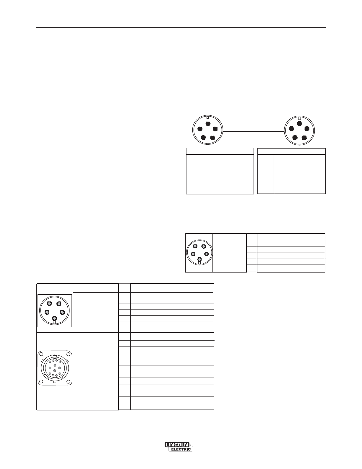
ARCLINK CONTROL CABLES
(See Figure A.3)
ArcLink Control Cables are available in two forms:
• K1543-xx series for most indoor or factory installations.
• K2683-xx series for outdoor use or when the equipment is frequently moved.
ArcLink/LincNet control cables are special high quality
cables for digital communication. The cables are copper 5 conductor cable in a SO-type rubber jacket.
There is one 20 gauge twisted pair for network communications. This pair has an impedance of approximately 120 ohms and a propagation delay per foot of
less than 2.1 nanoseconds. There are two 12 gauge
conductors that are used to supply 40VDC to the network. The fifth wire is 18 gauge and is used as an
electrode sense lead.
A-3
Use of non-standard cables may lead to system shutdowns, poor arc starting and wire feeding problems.
The control cables connect the power source to the
wire feeder, and the wire feeder to other wire feeders.
Control cables may be connected end to end to
extend their length. Use a maximum of 200 ft.
(61.0m) of control cable between components.
Figure A.3
POWER SOURCE
Power Source
Pin Function
A ArcLink
B ArcLink
C "67" voltage sense
D 40 VDC
E Common
Pin Function
A ArcLink
B ArcLink
C "67" voltage sense
D 40 VDC
E Common
WIRE FEEDER
Wire Feeder
CABLE CONNECTIONS
There are two circular connectors on the front of the
POWER FEED™ 25M.
(See 5-pin and 12-pin Figure A.1)
FIGURE A.1
Function
PIN
A
5-pin trigger connector for pushonly guns.
B
C
D
Dual Procedure Selection
E
A
B
12-pin connector
for remote control,
H
A
B
J
K
L
C
D
foot/hand amptrol,
G
M
push-pull guns and
F
ArcLink peripher-
E
als
C
75 Remote potentiometer, common
D
76 Remote potentiometer, wiper
E
77 Remote potentiometer, 5K
F
ArcLink Peripheral Sense
G
H
J
K
L
M
Wiring
Trigger
Not used
Common
Common
Trigger
Trigger
40VDC Common
40VDC +
Pull Motor –
Pull Motor +
CANL
CANH
There is one circular connector on the rear of the
POWER FEED™ 25M. Maximum control cable length
is 200 ft (61 m). (See Figure A.2)
FIGURE A.2
Function
5-pin ArcLink
connector.
PIN
A
B
C
67 Electrode Voltage Sense
D
E
Wiring
ArcLink
ArcLink
40VDC
Common
POWER FEED™ 25M
Page 11

A-4
Electrode
Work
Work
El ec t r ode
Wor k
El ec t r ode
W
or k
Power Sour ce
Coax i al W
el d Cabl e
Wi r e Feeder
WELD CABLE SIZE
INSTALLATION
To install:
1. Turn the input power off at the welding power source.
Table A.1 located below are copper cable sizes recommended for
different currents and duty cycles. Lengths stipulated are the distance from the welder to work and back to the welder again. Cable
sizes are increased for greater lengths primarily for the purpose of
minimizing cable drop.
2. Connect one end of the center lead to the power source
electrode connection, and the other end to the wire feeder electrode connection.
3. Connect the outer lead bundle to the power source work
connection, and the other end to the work piece.
Minimize the length of any work lead extension for best
COAXIAL WELD CABLE
(See Table A.2)
results.
4. Insulate all connections.
Coaxial welding cables are specially designed welding cables for
pulse welding or STT™ welding. Coaxial weld cables feature low
inductance, allowing fast changes in the weld current. Regular
cables have a higher inductance which may distort the pulse or
STT™ wave shape. Inductance becomes more severe as the weld
cables become longer.
Coaxial cables work best for high performance waveforms and
when:
• long cables are present.
• the cables are housed in a metal tray.
Power Sour c e
El ect r ode
A coaxial weld cable is constructed with multiple small leads
wrapped around one large lead. The large inner lead connects to
the electrode stud on the power source and the electrode connection on the wire feeder. The small leads combine together to form
the work lead, one end attached to the power source and the other
end to the work piece. See Figure A.5
TABLE A.2
RECOMMENDED CABLE SIZES (RUBBER COVERED COPPER - RATED 75°C)**
COAXIAL CABLE LENGTH
AMPERES
250
300
350
DUTY
CYCLE
100%
60%
60%
0 to 25Ft.
(0 to7.6M)
1
1
1/0
25 to 50Ft.
(7.6 to 15.2M)
1
1
1/0
FIGURE A.5
Coaxial W
(15.2 to 22.9M)
el d Cabl e
50 to 75 Ft.
1
1
--
Wi re Feeder
or k
75 to 100 Ft.
(22.9 to 30.5M)
1
1/0
--
A-4
TABLE A.1
RECOMMENDED CABLE SIZES (RUBBER COVERED COPPER - RATED 167°F or 75°C)**
CABLE SIZES FOR COMBINED LENGTHS OF ELECTRODE AND WORK CABLES
AMPERES
200
200
225
225
250
250
250
250
300
325
350
400
400
500
** Tabled values are for operation at ambient temperatures of 104°F(40°C) and below. Applications above 104°F(40°C) may require cables
larger than recommended, or cables rated higher than 167°F(75°C).
PERCENT
DUTY
CYCLE
60
100
20
40 & 30
30
40
60
100
60
100
60
60
100
60
0 to 50Ft.
(0 to15M)
2
2
4 or 5
3
3
2
1
1
1
2/0
1/0
2/0
3/0
2/0
50 to 100Ft.
(15 to 30M)
2
2
3
3
3
2
1
1
1
2/0
1/0
2/0
3/0
2/0
100 to 150 Ft.
(30 to 46M)
2
2
2
2
2
1
1
1
1
2/0
2/0
2/0
3/0
3/0
150 to 200 Ft.
(46 to 61M)
1
1
1
1
1
1
1
1
1/0
2/0
2/0
3/0
3/0
3/0
200 to 250 Ft.
(61 to 76M)
1/0
1/0
1/0
1/0
1/0
1/0
1/0
1/0
2/0
3/0
3/0
4/0
4/0
4/0
POWER FEED™ 25M
Page 12
A-5
SHIELDING GAS CONNECTION
INSTALLATION
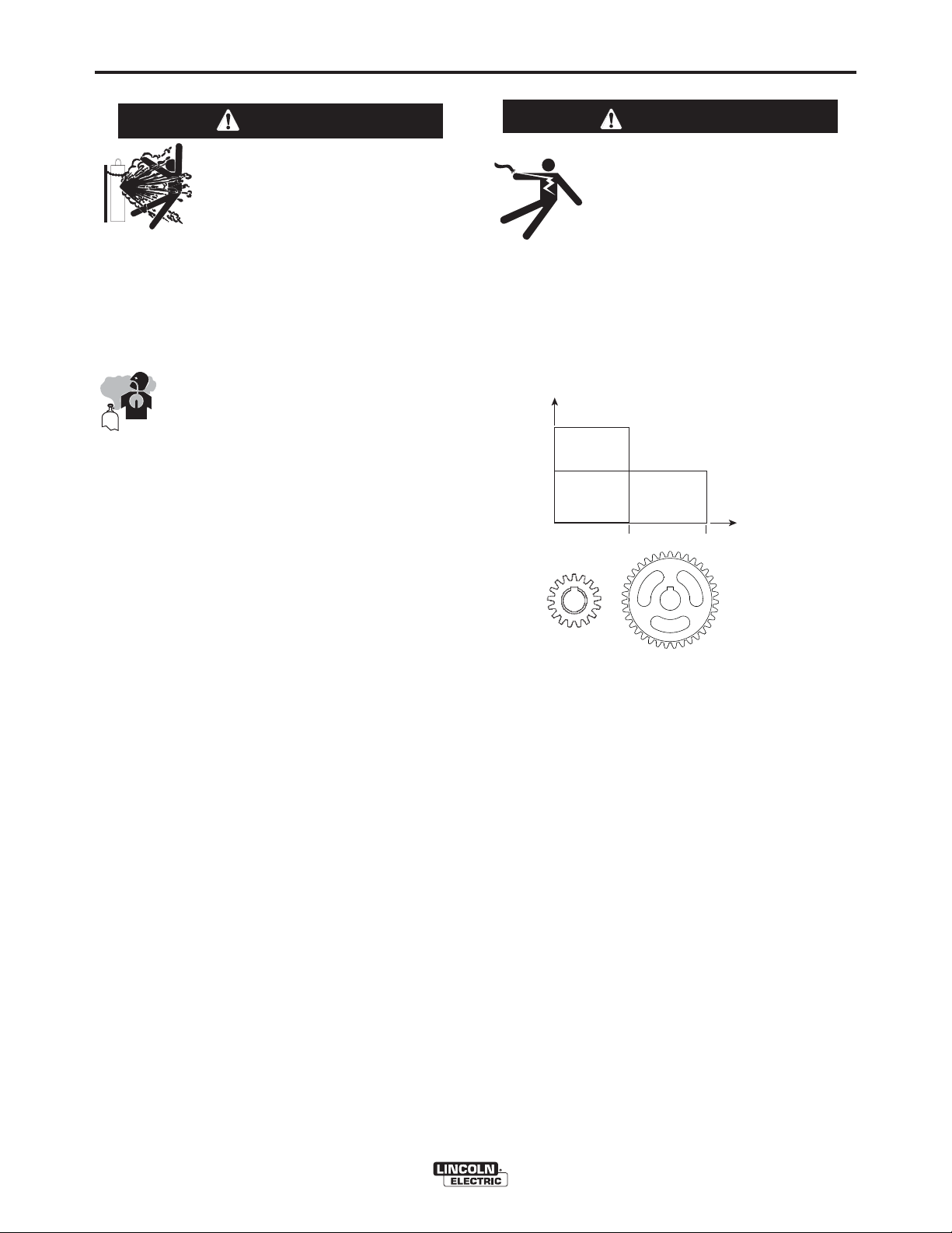
CHANGING THE DRIVE MOTOR GEAR RATIO
A-5
WARNING
CYLINDER may explode if
damaged.
• Keep cylinder upright and
chained to support.
• Keep cylinder away from areas where it may be
damaged.
• Never lift welder with cylinder attached.
• Never allow welding electrode to touch cylinder.
• Keep cylinder away from welding or other live
electrical circuits.
• BUILD UP OF SHIELDING GAS MAY
HARM HEALTH OR KILL.
• Shut off shielding gas supply when not
in use.
• See American National Standard Z-49.1, "Safety
in Welding and Cutting” Published by the
American Welding Society.
------------------------------------------------------------------------
M
AXIMUM INLET PRESSURE IS
Install the shielding gas supply as follows:
100
PSI
. (6.9
BAR
.)
WARNING
• Turn off input power at the welding power source before installation or changing drive roll and/or
wire guides.
• Do not touch electrically live parts
such as the wire drive or internal
wiring.
• When feeding with the gun trigger, the electrode
and wire drive mechanism are "hot" to work and
ground and could remain energized several seconds after the gun trigger is released.
• Only qualified personnel should perform this
operation.
------------------------------------------------------------------------
Extra
Torque
Gearing
Feed Force
400
Normal
Speed
Gearing
WFS
800
1. Secure the cylinder to prevent it from falling.
2. Remove the cylinder cap. Inspect the cylinder valves
and regulator for damaged threads, dirt, dust, oil or
grease. Remove dust and dirt with a clean cloth. DO
NOT ATTACH THE REGULATOR IF OIL, GREASE
OR DAMAGE IS PRESENT! Inform your gas supplier
of this condition. Oil or grease in the presence of high
pressure oxygen is explosive.
3. Stand to one side away from the outlet and open the
cylinder valve for an instant. This blows away any dust
or dirt which may have accumulated in the valve outlet.
4. Attach the flow regulator to the cylinder valve and
tighten the union nut(s) securely with a wrench. Note:
if connecting to 100% CO2cylinder, insert regulator
adapter between regulator and cylinder valve. If
adapter is equipped with a plastic washer, be sure it is
seated for connection to the CO2cylinder.
5. Attach one end of the inlet hose to the outlet fitting of
the flow regulator. Attach the other end to the welding
system shielding gas inlet. Tighten the union nuts with
a wrench.
6. Before opening the cylinder valve, turn the regulator
adjusting knob counterclockwise until the adjusting
spring pressure is released.
7. Standing to one side, open the cylinder valve slowly a
fraction of a turn. When the cylinder pressure gage
stops moving, open the valve fully.
8. The flow regulator is adjustable. Adjust it to the flow
rate recommended for the procedure and process
being used before making a weld.
Extra Torque
Gearing
Normal Speed
Gearing
Tools required:
• 1/4" hex key wrench
• 3/4" open end wrench
• 9/16" socket and ratchet wrench
• 7/16" nut driver
• 5/16" nut driver
• Phillips screw driver
1. Turn power off at the welding power source.
. Remove the spool of electrode from the wire feeder.
2
3. Loosen the thumb screw at the wire drive and remove the
welding gun.
4. Remove the outer wire guide, drive rolls and inner wire
guide.
5. Use a 7/16" nut driver to remove the gear cover.
6. Use 9/16" socket and ratchet wrench to remove the lower
drive roll hub retainer. Remove the lower drive roll hub.
7. With a Phillips screwdriver, remove the screw, washer
and collar holding the pinion gear. Remove the pinion
gear.
POWER FEED™ 25M
Page 13

A-6
8. Remove the busbar by unscrewing the bolt using a 3/4"
open end wrench.
9. With a 1/4" hex key wrench, loosen the socket head cap
screw securing the gun bushing. Remove the gun bushing from the wire drive.
10. With a 5/16" nut driver remove the five screws securing
the wire drive panel. Lift out the wire drive panel and
disconnect the molex connections.
11. Using a 5/16" nut driver, remove the four screws secur-
ing the cover.
12. With a Phillips screwdriver, remove the three screws
and lock washers securing the motor. Remove the
motor.
13. Place the motor in the new position.
14. Assemble the three screws and lock washer holding the
wire drive motor.
15. Assemble the molex connections and place the wire
drive assembly inside the wire feeder. Route the gas
hose through the opening in the wire drive panel.
INSTALLATION
A-6
16. Place the gun bushing in the wire drive and align the
threaded hole in the gun bushing with the hole in the
feed plate. With a 1/4" hex key, tighten the socket head
cap screw to secure the bushing in the wire drive.
17. Reassemble the busbar and tighten the mounting hard-
ware with a 3/4" open end wrench.
18. Place the new gear on the motor shaft. Secure the gear
to the motor shaft with the collar, washer and screw.
19. Reassemble the lower drive roll hub and lower drive roll
hub retainer.
20. Reassemble the gear cover.
21. Reassemble the inner wire guide, drive rolls and outer
wire guide.
22. Place the welding gun into the gun bushing and secure
with the thumb screw.
23. Restore power. Set the appropriate gear ratio using the
set-up menu.
POWER FEED™ 25M
Page 14
A-7
INSTALLATION
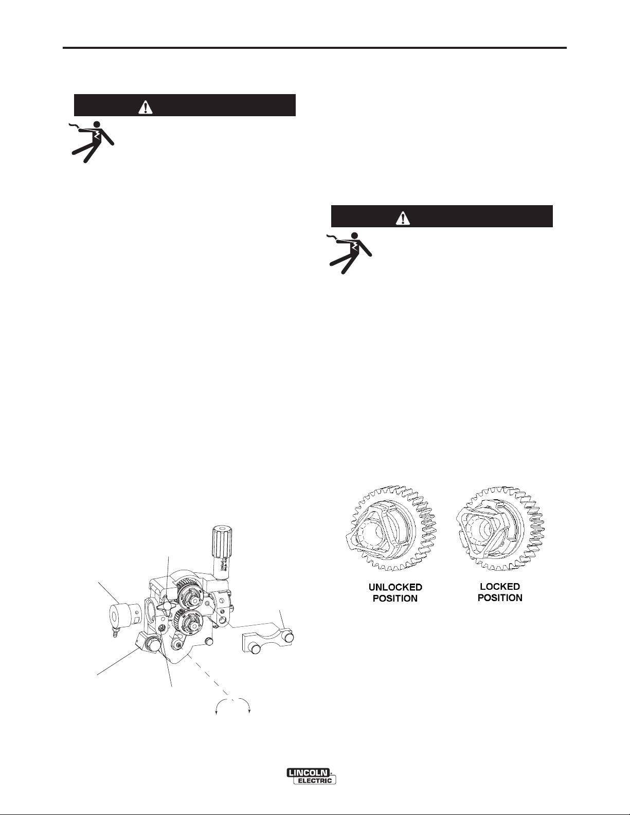
WIRE DRIVE CONFIGURATION
(See Figure A-6)
Changing the Gun Receiver Bushing
WARNING
ELECTRIC SHOCK can kill.
• Turn the input power OFF at the
welding power source before installation or changing drive rolls and/or
guides.
• Do not touch electrically live parts.
• When inching with the gun trigger, electrode
and drive mechanism are "hot" to work and
ground and could remain energized several seconds after the gun trigger is released.
• Only qualified personnel should perform maintenance work.
------------------------------------------------------------------------
Tools required:
• 1/4" hex key wrench.
Note: Some gun bushings do not require the use of
the thumb screw.
1. Turn power off at the welding power source.
2. Remove the welding wire from the wire drive.
3. Remove the thumb screw from the wire drive.
4. Remove the welding gun from the wire drive.
Loosen the socket head cap screw that holds the
5.
connector bar against the gun bushing.
Important: Do not attempt to completely
remove the socket head cap screw.
6. Remove the outer wire guide, and push the gun
bushing out of the wire drive. Because of the precision fit, light tapping may be required to remove
the gun bushing.
7. Disconnect the shielding gas hose from the gun
bushing, if required.
FIGURE A-6
A-7
8. Connect the shielding gas hose to the new gun
bushing, if required.
9. Rotate the gun bushing until the thumb screw hole
aligns with the thumb screw hole in the feed plate.
Slide the gun receiver bushing into the wire drive
and verify the thumb screw holes are aligned.
10. Tighten the socket head cap screw.
11. Insert the welding gun into the gun bushing and
tighten the thumb screw.
PROCEDURE TO INSTALL DRIVE ROLLS
AND WIRE GUIDES
WARNING
ELECTRIC SHOCK can kill.
• Turn the input power OFF at the
welding power source before installation or changing drive rolls and/or
guides.
• Do not touch electrically live parts.
• When inching with the gun trigger, electrode and
drive mechanism are "hot" to work and ground
and could remain energized several seconds
after the gun trigger is released.
• Only qualified personnel should perform maintenance work.
------------------------------------------------------------------------
1. Turn power off at the welding power source.
2. Release the idle roll pressure arm.
3.
Remove the outer wire guide by turning the knurled
thumbscrews counter-clockwise to unscrew them
from the feed plate.
4. Rotate the triangular lock and remove the drive
rolls.
GUN RECEIVER BUSHING
CONNECTOR BLOCK
THUMB SCREW
SOCKET HEAD
CAP SCREW
OUTER WIRE GUIDE
LOOSEN TIGHTEN
5. Remove the inner wire guide.
6. Insert the new inner wire guide, groove side out,
over the two locating pins in the feed plate.
7. Install a drive roll on each hub assembly secure
with the triangular lock.
8. Install the outer wire guide by aligning it with the
pins and tightening the knurled thumbscrews.
9. Close the idle arm and engage the idle roll pressure
arm. Adjust the pressure appropriately
POWER FEED™ 25M
Page 15

A-8
CONNECT AALL SSENSE
LEADS
THE EEND
O
THE WWELD
CONNECT
A
LL
WORK
LEAD
S
AT
THE BBEG
INN
IN
G
OF
THE
WELD
DIRE
C
TI ON
OF
TRAVEL
INSTALLATION
A-8
REMOTE SENSE LEAD SPECIFICATIONS
Welding with Multiple Arcs:
( See Figure A.7)
Special care must be taken when more than one arc
is welding simultaneously on a single part. Arc blow
and arc interference may occur or be magnified. Each
power source requires a work lead from the work stud
to the welding fixture. Do not combine all of the work
leads into one lead. Performing welding in the direction away from the work leads. Connect all of the work
sense leads from each power source to the work
piece at the end of the weld, such that they are out of
the path of the weld current. See Figure A.7
For the best results when pulse welding, set the wire
size and wire feed speed the same for all the arcs.
When these parameters are identical, the pulsing frequency will be the same, helping to stabilize the arcs.
LOADING SPOOLS OF WIRE
WARNING
• Keep hands, hair, clothing and tools
away from rotating equipment.
• Do not wear gloves when threading
wire or changing wire spool.
• Only qualified personnel should install,
use or service this equipment.
------------------------------------------------------------------------
Loading 10 to 15 lb. (4.5 – 6.8kg) Spools.
A K468 spindle adapter is required for loading 2"
(51mm) wide spools on 2" (51mm) spindles. Use a
K468 spindle adapter for loading 2-1/2" (64mm) wide
spools.
Squeeze the release bar on the retaining collar and
1.
remove it from the spindle.
2. Place the spindle adapter on the spindle, aligning
the spindle brake pin with the hole in the adapter.
3. Place the spool on the spindle and align the
adapter brake tab with one of the holes in the back
side of the spool. An indicator mark on the end of
the spindle shows the orientation of the brake tab.
Be certain the wire feeds off of the spool in the
proper direction.
OF
L
TH
W
FIGURE A.7
TI O
A
A
G
INN
4. Re-install the retaining collar. Make sure that the
release bar snaps out and that the retaining collar
fully engages the groove on the spindle.
AAT TH
F FTH
POWER FEED™ 25M
Page 16

A-9
INSTALLATION
A-9
TYPICAL SYSTEM CONFIGURATIONS
Standard Features
Arc Performance
• Push-Pull ready for welding aluminum with Pulse
and Pulse-on-Pulse™ waveforms.
• STT™ capable when used with STT™ equipped
Power Waves.
• Waveform Control Technology™ for welds with
good appearance and low spatter, even when welding nickel alloys.
Wire Drive
Patented 2 roll drive system. MAXTRAC™ technology
delivers great feeding because:
• Patent pending drive rolls improve traction on solid
wire by up to 20%.
• The precision machined, rigid aluminum alloy frame
results in maximum drive roll clamping pressure.
Extras:
• Flowmeter with gas control valve
• Push-Pull ready.
• Remote control / Foot amptrol ready.
• Internal heater for keeping condensation off of the
spool of wire.
• Internal lights for illuminating the wire drive compartment.
Options
• Water cooling kit for use with water cooled guns.
• Patented split wire guides fully support the wire and
virtually eliminate birdnesting.
• No tools required to change the drive rolls and wire
guides.
• Patented dual spring pressure arms have sensitivity
for feeding soft wires without crushing them, and
have plenty of compression force for feeding solid or
stiff wires.
• All gear driven rolls for more feeding force.
• Changeable gun bushings easily accept guns from
other manufacturers.
• Brass-to-brass connections between the electrode
connection and the gun minimize voltage drop variations, resulting in consistent arc performance all
day, every day.
• Powerful, quiet motor with integrated tachometer for
accurate WFS regulation.
POWER FEED™ 25M
Page 17

B-1
OPERATION
SAFETY PRECAUTIONS
READ AND UNDERSTAND ENTIRE SECTION
BEFORE OPERATING MACHINE.
B-1
GRAPHIC SYMBOLS THAT APPEAR ON
THIS MACHINE OR IN THIS MANUAL
WARNING
• ELECTRIC SHOCK CAN KILL.
Unless using COLD FEED feature, when feeding with gun trigger, the electrode and drive
mechanism are always electrically energized and could
remain energized several seconds after the welding ceases.
• Turn the input power OFF at the welding power
source before installation or changing drive
rolls and/or guides.
• Do not touch electrically live parts.
• When inching with the gun trigger, electrode
and drive mechanism are "hot" to work and
ground and could remain energized several
seconds after the gun trigger is released.
• Do not operate with covers, panels or guards
removed or open.
• Only qualified personnel should perform maintenance work.
----------------------------------------------------------------------
• FUMES AND GASSES can be
dangerous.
• Keep your head out of fumes.
Use ventilation or exhaust to
•
remove fumes from breathing
zone.
----------------------------------------------------------------------
• WELDING SPARKS can cause
fire or explosion.
• Keep flammable material away.
U
U
INPUT POWER
ON
OFF
WIRE FEEDER
POSITIVE OUTPUT
NEGATIVE OUTPUT
INPUT POWER
DIRECT CURRENT
0
1
OPEN CIRCUIT
VOLTAGE
INPUT VOLTAGE
----------------------------------------------------------------------
ARC RAYS can burn.
Wear eye, ear and body protec-
•
tion.
----------------------------------------------------------------------
SEE ADDITIONAL WARNING INFORMATION
UNDER ARC WELDING SAFETY PRECAUTIONS
AND IN THE
UAL.
----------------------------------------------------------------------
FRONT OF THIS OPERATING MAN-
POWER FEED™ 25M
U
I
I
2
1
2
OUTPUT VOLTAGE
INPUT CURRENT
OUTPUT CURRENT
PROTECTIVE
GROUND
WARNING OR
CAUTION
Page 18

B-2
OPERATION
B-2
DEFINITION OF WELDING TERMS
NON-SYNERGIC WELDING MODES
• A Non-synergic welding mode requires all welding
process variables to be set by the operator.
SYNERGIC WELDING MODES
• A Synergic welding mode offers the simplicity of
single knob control. The machine will select the correct voltage and amperage based on the wire feed
speed (WFS) set by the operator.
WFS
• Wire Feed Speed
CC
• Constant Current
CV
• Constant Voltage
GMAW
• Gas Metal Arc Welding
GMAW-P
• Gas Metal Arc Welding-(Pulse Arc)
GMAW-STT
• Gas Metal Arc Welding-(Surface Tension Transfer)
SMAW
• Shielded Metal Arc Welding
FCAW
• Flux Core Arc Welding
CAG
• Carbon Arc Gouging
GENERAL DESCRIPTION
General Physical Description
The POWER FEED™ 25M is a premium portable wire
feeder for use with the Power Wave products. The
wire feeder features a 2 roll MAXtrac™ drive coupled
to a powerful motor for driving wire through difficult situations. The easy-to-use, user interface provides
ready access to all welding modes in the Power
Wave. Built in memories are included with the
POWER FEED™ 25M and allows quick recall of
favorite weld procedures. Two cases are available:
an engineered aluminum case with replaceable skids,
or an impact resistant polycarbonate plastic case.
The heart of the POWER FEED™ 25M is the
MAXtrac™ drive. The patented features on the wire
drive offer tool-less changing of the drive rolls and the
wire guides for quick spool changes. Plus, the drive
can be configured for extra torque when feeding large
diameter flux cored electrodes.
The POWER FEED™ 25M continues Lincolnʼs lead
role of environmental protection for electronics. P.C.
boards are potted in epoxy and electrical connections
are protected with dielectric grease. Noise suppression components protect the POWER FEED™ 25M
from stray signals and keep the feeder from interfering
with other digital equipment.
General Functional Description
The POWER FEED™ 25M is best suited for applications were quality welds are expected. Combined with
a Power Wave power source, the POWER FEED™
25M is great for aluminum, nickel, alloy and other difficult to weld materials. Easy to use controls make it a
great feeder for consistent results with mild steel
applications too.
DUTY CYCLE
The POWER FEED™ 25M is rated for 500 amps,
60% duty cycle. The duty cycle is based on a 10
minute cycle.
For example, when welding at 500 amps, the POWER
FEED™ 25M may run continuously for 6 minutes and
then must sit idle for 4 minutes.
POWER FEED™ 25M
Page 19

B-3
OPERATION
RECOMMENDED PROCESSES
• GMAW (CV, Synergic CV, Pulse, STT™, Power,
Pulse on Pulse™, Push-Pull)
• FCAW
• SMAW
• GTAW (Lift Start only)
• Solid wires .025" to 1/16"
• Cored wires .035" to 5/64"
• Cored wires .035" to 3/32" when configured for
"extra torque"
EQUIPMENT LIMITATIONS
• Works only on ArcLink®Power Wave power
sources.
• Maximum gun length is 25ft.(7.6m) for push-only
systems.
• Maximum gun length is 50ft.(15.2m) for push-pull
systems.
• A remote control/foot amptrol and a push-pull gun
may not be connected to the POWER FEED™ 25M
simultaneously.
• Maximum spool size is 12 in. (305 mm) diameter
• Maximum spool weight is 44 lb (20 kg).
• Maximum control cable length is 200 ft (61 m).
• Other gun bushings are required for welding guns
that do not have a Magnum (Tweco #2-#4 compatible) back end.
• No more than 2 wire feeders may be connected to
one ArcLink power source at a time.
B-3
RECOMMENDED POWER SOURCES
• Power Wave®355M
• Power Wave
• Power Wave
• Power Wave
• Power Wave
• Power Wave
• Power Wave
®
455M
®
455M/STT
®
655/R
®
S350
®
R350
®
i400
POWER FEED™ 25M
Page 20

B-4
CASE FRONT CONTROLS
(SEE FIGURE B.1)
OPERATION
15. Thermal
Lights when the drive overheats.
B-4
1. Left DISPLAY window
Shows WIRE FEED SPEED or AMPERAGE.
2. Left KNOB
Adjusts values in left display.
3. Status LED
Illuminates a steady green when communicating to
the power source properly.
4. Main display
Shows detailed welding and diagnostic information.
5. Left Button
Changes the Main display to show the Weld Mode
or UltimArc.
6. Procedure Button
Selects A or B procedure, or gun control.
7. 2-Step/4-Step Button
Toggles between 2-step and 4-step trigger operation.
8. 5-pin connector
Trigger connector for a push-only gun.
16. Set-Up
Lights when feeder is set-up.
17. Right Button
Changes the Main display to show Start Options or
End Options.
18. Set Knob
Changes the value on the Main display.
19. Memories Buttons
For selection of common procedures.
FIGURE B.1
1
2
3
4
5
6
13
14
15
16
17
18
9. ON/OFF switch
Controls power to the POWER FEED™ 25M.
10. 3 Amp Circuit Breaker
Protects the 12-pin accessories
11. 12-pin connector
Connection for push-pull guns, remotes
12. Cover
Covers location for optional water cooling line.
13. Right Display window
Shows VOLTAGE or TRIM.
14. Right Knob
Adjusts values in the right display.
7
9
10
11
12
19
8
POWER FEED™ 25M
Page 21
B-5
OPERATION
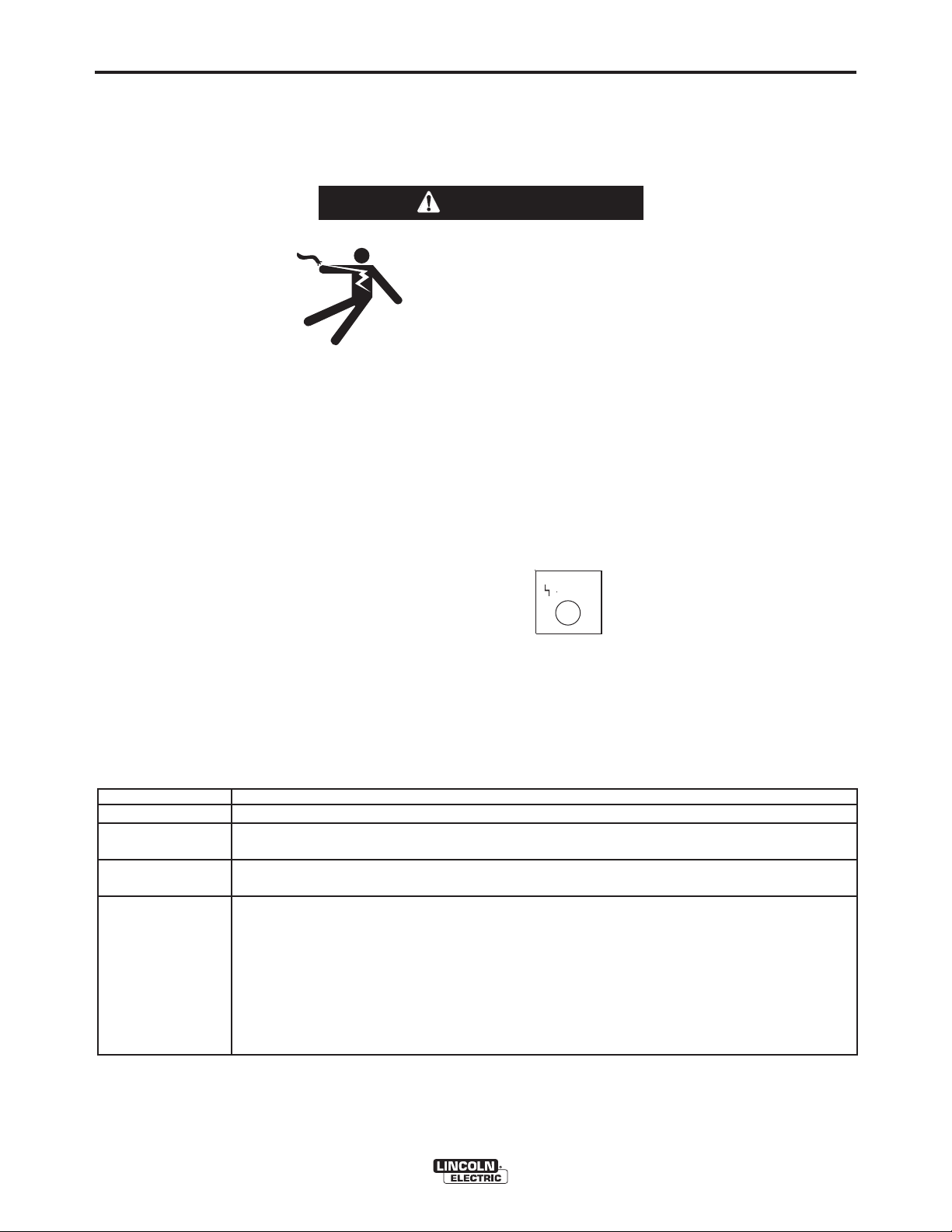
9. ON-OFF SWITCH
The On-Off Switch turns the wire feeder power on and
off. It does not control the power to the welding power
source.
WARNING
ELECTRIC SHOCK can kill.
• Turn the input power OFF at the
welding power source before
installation or changing drive
rolls and/or guides.
• Do not touch electrically live
parts.
• When inching with the gun trigger, electrode and
drive mechanism are "hot" to work and ground
and could remain energized several seconds
after the gun trigger is released.
• Welding power source must be connected to
system ground per the National Electrical Code
or any applicable local codes.
• Only qualified personnel should perform maintenance work.
------------------------------------------------------------------------
B-5
LED condition
Steady green
Blinking green.
Blinking green, fast
Blinking green followed by blinking
red.
STATUS LED
(See Table B.1)
The status LED indicates system status. Normal
operation is a steady green light.
Note: During normal power-up, the LED may flash
red and/or green as the equipment performs self tests.
TABLE B.1
Definition
System okay. The power source and wire feeder are communicating normally.
Occurs during a reset and indicates the power source is identifying each component in the system. This is
normal for up to 15 seconds after power-up, or if the system configuration is changed during operation.
Indicates that one or more pieces of ArcLink equipment are not mapping properly.
Non-recoverable system fault. If the power source or wire feeder status LED is flashing any combination of
red and green, errors are present in the system. Read the error code before the machine is turned off.
Instructions for reading the error code are detailed in the Service Manual. Individual code digits are flashed
in red with a long pause between digits. If more than one code is present, the codes will be separated by a
green light.
STAT
US
To clear the error, turn the power source OFF, and then back ON to reset. See Troubleshooting Section E.
POWER FEED™ 25M
Page 22

B-6
Lorem ipsum dolor sit
am
e
t cons
ectetuer adip
iscin
g
elit, ed diam
non
ummy ni
bh e
uismod tincidun
t ut
laoreet dolore magna al
iqu
am er
at
Lo
rem
ipsum dolor s
it ame
t c
onsectetuer adipis
cing
elit, ed diam nonummy nib
h
euismod tincidunt ut
laoreet dolo
re magna al
iquam
erat
Lorem ipsum do
lor sit ame
t consectetuer
adipiscing
elit
, ed diam n
onummy ni
bh euismod
tinc
idunt ut
laor
eet dolore m
agna al
iqu
am er
at
Lorem ipsum dolor sit am
et
con
sec
tetuer a
dipiscing
elit, ed
diam nonum
my ni
bh
eu
ismod tincidun
t ut
laoreet
dolore magna
al
iq
uam erat
Lorem ipsum dolor sit
am
et consectetue
r adipisc
in
g
elit, ed diam nonum
my nib
h euismod
tincidunt ut
laoreet dolore magna al
iquam er
at
Lorem
ips
um dol
or sit
am
et consectetuer adipiscin
g
elit, ed diam
nonummy
ni
bh euismod tincidunt ut
laoreet do
lore m
agna al
iquam erat
Lo
rem ipsum dolor
s
it am
et consectetuer adipiscin
g
elit, ed diam
nonummy
nib
h euis
mod tinc
idunt ut
laoreet dolo
re
magna al
iquam erat
Lore
m ipsum d
olor sit am
et consectetuer adipis
cing
elit,
ed diam nonumm
y ni
bh euismod tincidunt ut
laoreet dolore
m
agna
al
iquam erat
Lorem ip
sum dolor
sit am
et consec
tetuer
adipiscing
elit, ed
diam nonummy ni
bh
euismod tincidunt u
t
lao
reet dolore mag
na al
iquam erat
Lorem ipsum dolor sit am
et consectetue
r adipiscing
elit, ed dia
m nonummy nib
h euism
od tinc
idunt ut
laoreet dolore magna al
iquam
erat
Lorem ipsum dolor sit am
et co
nsectetuer adipiscing
elit
, ed diam nonummy ni
bh
euis
mod tincidunt ut
laor
eet dolore magna al
iquam erat
Lorem ipsum dolor sit am
et con
sectetuer adip
iscing
elit
, ed diam n
onum
my nib
h euismod tincidu
nt ut
laoreet dolo
re m
agna al
iquam erat
Lorem ipsum dolor sit am
et co
nsectetuer adipiscing
elit, ed
diam
nonu
mmy ni
bh euis
mod tinc
idunt ut
laoreet dolore
magna al
iquam erat
L
o
re
m
i
p
su
m
d
o
lo
r s
it
a
m
e
t
c
o
n
s
e
c
te
tu
e
r
a
d
ip
is
c
in
g
e
lit,
e
d
d
i
a
m
n
o
n
u
m
m
y
n
i
b
h
e
u
is
m
o
d
tin
c
i
d
u
n
t u
t
la
o
re
e
t d
o
lo
re
m
a
g
n
a
a
liq
u
a
m
e
r
a
t
L
o
r
e
m
ip
s
u
m
d
o
lo
r
s
it
a
m
e
t
c
o
n
s
e
c
te
t
u
e
r
a
d
i
p
is
c
in
g
e
l
it, e
d
d
i
a
m
n
o
n
u
m
m
y
n
ib
h
e
u
i
s
m
o
d
tin
c
id
u
n
t u
t
la
o
re
e
t
d
o
lo
r
e
m
a
g
n
a
a
li
q
u
a
m
e
r
a
t
L
o
r
e
m
ip
s
u
m
d
o
lo
r s
it a
m
e
t
c
o
n
s
e
c
te
tu
e
r
a
d
ip
is
c
i
n
g
e
lit,
e
d
d
i
a
m
n
o
n
u
m
m
y
n
i
b
h
e
u
is
m
o
d
t
in
c
i
d
u
n
t
u
t
la
o
r
e
e
t d
o
lo
re
m
a
g
n
a
a
li
q
u
a
m
e
r
a
t
L
o
re
m
ip
s
u
m
d
o
lo
r s
it
a
m
e
t
c
o
n
s
e
c
te
tu
e
r
a
d
i
p
i
s
c
in
g
e
lit,
e
d
d
i
a
m
n
o
n
u
m
m
y
n
i
b
h
e
u
i
s
m
o
d
tin
c
id
u
n
t
u
t
l
a
o
r
e
e
t d
o
lo
re
m
a
g
n
a
a
liq
u
a
m
e
ra
t
Lorem
ips
um dolor sit a
me
t consectetuer adipisc
ing
elit, ed diam non
ummy nib
h euismod tincidunt
ut
laoreet
dolore magna a
l
iqu
am erat
Lorem ipsum d
olor sit am
et consectetuer adipiscin
g
elit, ed diam no
numm
y nib
h eu
ism
od tin
cidunt ut
laoreet
dolore magna al
iquam erat
OPERATION
POWER WAVE SYSTEM OPERATION
WARNING
The serviceability of a product or structure utilizing
the welding programs is and must be the sole
responsibility of the builder/user. Many variables
beyond the control of The Lincoln Electric Company
affect the results obtained in applying these programs. These variables include, but are not limited
to, welding procedure, plate chemistry and temperature, weldment design, fabrication methods and service requirements. The available range of a welding
program may not be suitable for all applications, and
the build/user is and must be solely responsible for
welding program selection.
------------------------------------------------------------------------
The steps for operating the Power Wave will vary
depending upon the user interface of the welding system. The flexibility of the Power Wave lets the user
customize operation for the best performance.
B-6
FIGURE B.2
!
WARNING
!
WARNING
L
o
re
m
e
l
i
i
t
p
,
s
e
l
u
a
d
m
o
d
re
L
d
i
o
a
e
o
re
m
t
l
o
d
m
e
r
n
o
l
on
s
i
l
i
t
o
p
i
,
t
re
su
u
e
a
l
a
m
d
m
m
o
m
my
d
re
e
a
L
i
d
t
a
g
e
o
o
c
m
n
n
t
re
l
o
o
a
i
d
n
b
m
n
r
o
e
s
h
a
o
s
l
l
e
o
l
i
i
n
i
i
eu
t
p
t
qu
cte
,
re
u
s
a
e
m
l
i
u
a
me
a
s
d
m
t
m
o
m
u
m
m
d
a
re
e
t
y
o
i
d
g
r
e
a
co
e
d
o
n
n
rat
a
m
t
L
l
a
i
t
d
o
b
n
d
i
o
n
i
n
r
h
s
a
o
p
re
c
o
e
s
l
l
i
i
e
i
o
s
n
q
i
m
c
d
t
e
u
c
re
t
u
u
u
a
e
l
i
i
i
n
m
a
i
s
n
t
m
p
t
,
m
m
g
u
m
t
s
m
e
e
e
l
u
u
a
o
a
d
t
r
y
e
t
m
g
d
o
c
rat
a
d
n
n
re
o
ti
d
i
d
a
i
a
b
n
n
e
!
i
o
p
m
h
se
c
a
t
l
i
o
i
l
sc
L
d
d
i
e
q
n
c
r
o
o
u
u
t
u
i
o
s
re
l
n
e
n
i
o
a
s
n
i
g
t
t
t
r
m
m
u
m
u
e
e
a
u
e
mm
l
o
m
t
i
ma
i
r
e
t
p
d
ATTENTION
,
e
ra
a
su
e
t
t
l
y
d
a
g
i
t
d
n
c
i
m
o
n
n
p
L
c
o
d
re
a
i
i
o
i
b
s
n
d
i
d
re
a
ci
h
s
a
e
u
!
o
m
e
l
t
n
n
m
l
i
e
e
o
q
c
d
g
t
u
l
n
r
t
u
o
i
u
i
e
i
t
p
o
a
s
s
,
l
AVISO DE
t
t
o
su
n
m
i
u
m
e
t
l
re
a
u
e
d
a
o
m
o
mmy
r
e
d
m
d
m
re
ra
a
i
d
e
t
d
a
a
i
e
t
o
n
t
i
m
g
p
t
l
c
co
o
n
n
d
i
i
s
n
d
r
a
i
o
b
n
c
PRECAUCION
o
u
s
l
i
h
se
a
o
n
n
n
i
t
L
l
re
g
u
t
i
e
a
q
o
c
m
u
u
m
tet
u
re
m
t
i
am
m
s
e
m
a
m
u
e
t
y
g
e
L
l
o
c
e
i
i
n
n
t
r
o
p
L
o
,
d
a
i
ra
r
s
a
b
n
e
o
e
l
t
u
a
d
h
s
a
d
i
t
m
n
m
r
o
i
e
e
l
p
e
i
e
c
d
re
l
q
c
i
i
e
i
i
u
s
t
i
d
p
m
d
te
u
a
,
e
c
i
l
o
s
u
a
sm
m
i
e
t
t
l
i
t
u
l
a
n
n
u
m
o
d
l
,
d
i
m
o
g
t
e
e
p
n
r
o
a
o
d
s
r
L
u
r
e
o
d
s
l
e
i
d
o
o
o
t
ra
a
d
n
a
i
L
e
t
u
o
r
r
t
d
r
u
m
d
i
e
t
e
a
t
o
l
n
e
m
i
m
or
p
d
m
m
ci
m
e
re
n
e
i
i
o
my
s
a
l
e
o
d
s
i
a
l
i
e
t
d
c
t
o
p
t
m
n
u
i
m
,
g
t
i
l
re
d
su
o
c
n
u
n
e
i
n
n
l
a
a
t,
o
g
m
t
o
d
l
l
a
i
m
i
m
o
b
o
n
n
m
u
p
l
m
a
d
h
re
e
s
a
et
o
t
r
o
a
L
s
i
d
e
o
l
y
a
d
i
e
r
g
e
ore
n
s
q
o
u
c
c
m
e
r
u
n
n
t
te
u
l
i
u
o
e
m d
o
d
t
i
a
i
d
a
s
b
ns
m
n
r
ma
t
mmy
e
o
i
el
a
m
u
m era
h
a
a
o
s
l
e
t
e
o
l
i
me
i
n
i
o
i
e
t
m
p
t
r
q
ct
,
re
d
o
u
d
u
s
g
a
u
a
e
m
l
t
e
L
i
o
u
l
ma
a
me
a
s
d
n
d
o
n
i
t
o
t
t
m
o
nc
m
m
u
l
m
i
n
a
p
o
re
r
d
o
re
c
er
t
y
o
i
i
d
i
i
g
co
r
s
e
n
a
s
o
d
m
b
n
e
d
a
e
e
o
n
c
ra
m
a
u
i
u
t
n
h
l
i
l
a
l
i
t
t
i
n
o
d
n
i
b
n
i
d
i
t
a
p
t
ma
mmy
se
n
q
,
n
g
r
i
t
h
s
a
o
p
e
s
c
e
o
e
u
s
u
l
l
l
me
u
i
a
i
e
i
o
u
s
d
n
q
i
c
t
d
ct
m
t
a
o
u
ci
r
g
t
u
u
u
i
e
d
a
et
re
i
s
m e
m
a
n
s
n
e
n
i
d
me
t
a
ma
mo
m
u
m
g
t
e
o
t
m
n
a
m
e
c
u
u
t
l
o
o
i
t
r ad
y
e
t
d
o
g
b
d
e
a
L
n
r
r
c
ra
o
d
n
n
a
n
h
o
o
r
o
s
l
t
l
a
i
i
i
o
t
re
b
n
n
i
n
t
s
q
i
t
ti
a
pi
re
e
h
u
s
ci
a
e
a
u
m
n
d
e
e
mm
l
sc
u
d
m
i
eu
c
ma
q
a
c
c
l
i
un
i
i
i
p
t
t
u
t
i
e
p
s
i
m e
n
,
e
i
e
d
a
s
t
s
y
i
g
e
mo
t
t
g
s
l
m
u
u
ut
m e
t
c
a
u
d
na
n
u
c
o
e
m
o
o
n
i
b
d
n
r ad
e
i
re
r
d
n
d
t
h
i
se
d
a
r
L
a
a
r
u
a
e
t
g
o
l
o
m
i
i
e
t
t
t
ti
q
a
n
c
l
i
re
o
u
p
t
d
t
u
ci
n
d
e
n
r
i
i
m
o
a
s
sc
d
e
t
cid
o
s
i
l
m
u
m
p
o
u
l
n
i
i
i
i
t
e
t
n
p
re
n
o
u
i
,
a
r
e
s
g
s
t
1
6
W
ARNING
RE
M
O
T
E
P
O
W
E
R
O
N
O
F
F
d
m
u
e
ma
l
m
ra
a
u
c
a
u
d
n
ti
m
d
m
o
t
e
i
t
n
n
i
d
t
re
t
p
y
do
c
g
i
g
c
i
am
u
i
s
n
e
n
d
o
c
a
t
t
i
u
l
b
n
o
i
d
n
n
n
h
s
a
r
o
g
t
e
l
o
s
i
e
l
u
q
c
o
nu
i
u
t
t
t
u
r
a
e
i
e
a
sm
L
m
tu
m
m
m
L
o
m
e
o
e
o
a
r
r
e
r
t
y
d
e
g
c
e
r
a
e
a
n
n
e
m
m
t
d
on
i
t
l
a
i
n
i
b
i
l
ipsu
p
it, e
a
t
c
h
s
,
is
i
i
l
e
p
d
l
lao
a
i
e
e
ci
q
c
u
L
s
d
uis
o
t
ua
d
n
n
m
L
o
e
d
u
g
r
t
r
r
tu
o
e
e
e
m
m
m
d
i
ut
do
a
e
e
m
r
e
e
i
o
m
e
e
t d
a
r
lo
li
i
d
e
t
a
d
r
n
m
t
m
p
t
r
a
, e
l
d
olo
o
d
sum
i
l
i
on
t
s
n
t
i
i
o
l
a
l
p
i
,
d
o
c
n
t
r
p
o
a
i
u
lo
a
i
sc
e
e
d
r
d
o
r
m
su
e
o
m
u
ia
d
d
m
r
n
si
in
e
m
n
o
e
r
e
m
a
u
t
e
g
t u
m
l
d
t
t
y
m
o
g
do
m
e
n
co
n
i
r
a
n
a
t
o
s
t
d
a
i
l
m
a
m
b
o
n
d
m
n
it a
o
h
secte
r
a
g
u
e
e
y
e
l
o
l
m
i
n
m
m
o
n
q
t
l
u
m
n
u
a
o
r
o
et
co
i
a
a
s
i
y n
r
tu
n
si
gn
b
m
m
a
e
co
u
e
n
h
t
l
o
a
i
i
r
e
b
m
n
m
se
d
q
e
a
r
a
h
secte
a
tinci
a
u
m
d
a
l
m
u
t
iqu
e
ct
i
a
p
g
u
i
e
y
sm
m
i
i
e
sc
n
a
sm
d
t
tu
m
t
u
n
a
in
co
u
e
e
n
i
o
o
b
r
e
g
e
t
a
r
d
d
r
a
u
n
a
h
r
l
a
ti
i
d
t
t
s
t
q
t
n
a
ipisc
e
i
e
ci
u
n
d
u
ct
d
a
ci
i
i
p
un
s
m
i
e
n
d
i
m
sci
g
t
t
u
u
ut
e
o
n
e
r
n
d
t
a
r
u
g
t
t
a
i
t
n
d
c
i
p
i
d
i
sc
u
n
i
n
t
g
u
t
3 5 5
E
A V
E R W
P O W
4
3
First, consider the desired welding process and the
part to be welded. Choose an electrode material,
diameter, shielding gas and process (GMAW, GMAWP, GMAW-STT™, etc.)
Second, find the program in the welding software that
best matches the desired welding process. The standard software shipped with the Power Waves encompasses a wide range of common processes and will
meet most needs. If a special welding program is
desired, contact the local Lincoln Electric sales representative.
All adjustments are made on the user interface.
Because of the different configuration options your
system may not have all of the following adjustments.
Regardless of availability, all controls are described
below.
SMAW (STICK) WELDING
SMAW is most often used for outdoor construction,
pipe welding and general repairs. The wire feeder
controls Amperage, Output Control and Arc Force during SMAW welding.
During SMAW welding, the user interface sets the
weld parameters and the wire drive remains idle.
2
K2202-1 Power Wave®455M
1 K2203-1 Power Wave
K2823-xx Power Wave
K2230-1 POWER FEED™ 10M, Bench
Model
2 K2234-1
POWER FEED™ 10M Dual,
Bench Model
K2536-4, -5 POWER FEED™ 25M
3 K2683-xx Heavy Duty ArcLink Cable
K1543-xx ArcLink Control Cable
4 K1842-xx Weld Power Cable, Lug to Lug
K910-xx Ground Clamp
5 K909-xx Electrode Holder
6 K2176-1 Twist-Mate to Lug Cable Adapter
K960-3 Tweco Style Cam Lock Torch
Adapter
®
455M/STT
®
S350
5
The “Volts”-”Trim” control is used to turn the power
Source Output ON or OFF. (See Figure B.3)
SMAW Welding (See Figure B.2)
POWER FEED™ 25M
Page 23

OPERATION
SMAW (STICK) WELDING
SMAW is most often used for outdoor construction,
pipe welding and general repairs. The wire feeder
controls Amperage, Output Control and Arc Force during SMAW welding.
During SMAW welding the wire drive remains idle.
BASIC OPERATION
B-7B-7
CC STICK MODES
PROCESS
Stick Soft(7018)
Stick Crisp(6010)
EFFECT / RANGE
ARC FORCE
(Soft)-10.0 to
(Crisp)+10.0
WFS
AMPS
LESS
AMPS
194
+
MORE
AMPS
CONTROL OPTIONS
MODE
1
2
WELD MODE
UltimArc™ Control
UltimArc™ Control
DESCRIPTION
Arc Force adjusts the short circuit current for a soft arc, or for
a forceful, driving arc. It helps
to prevent sticking and shorting
electrodes,
of organic
ticularity globular transfer types
such as stainless and low
hydrogen. Arc Force is especially effective for root pass on
pipe with stainless electrode
and helps to minimize spatter
for certain electrodes and procedure as with low hydrogen,
etc.
coated
OUTPUT
OFF
2
Stick Crisp
par
-
OUTPUT
ON
VOLTS
TRIM
0
n
+
START OPTIONS
No arc starting
SMAW
SETUP
START OPTIONS
END OPTIONS
options are
(Stick) welding modes.
END OPTIONS
No arc ending options are active for
SMAW
(Stick) welding modes.
active for
NOTE: When a remote control pot such as a K936-1 or -2
Hand Amptrol is connected, and P.17 is setup for
Stick/Gouge Remote, the pot value will be shown
on the left display, but can only be adjusted to the
max workpoint. The max workpoint is set by adjusting the left knob. When the left knob is adjusted,
the left display will show the max workpoint setting,
and will switch back to show the pot setting when
the knob is done being adjusted.
POWER FEED™ 25M
Page 24

B-8
OPERATION
SET-UP, PHYSICAL, NON-SYNERGIC
GMAW AND FCAW WELDING
(See Figure B.4)
B-8
Three non-synergic welding modes are available.
Description Mode Used for:
GMAW, Standard CV 5 Best for traditional
MIG welding.
Non-synergic GMAW and FCAW welding mimics the
welding controls of traditional welding power sources.
Voltage and WFS are set as independent variables.
FIGURE B.4
6
4
2
3
GMAW, Power 40 Specialized GMAW
mode.
FCAW 6 Best for self shield-
ed electrodes like
Innershield™.
1
5
K2202-1 Power Wave®455M
®
1 K2203-1 Power Wave
K2823-xx Power Wave
K2230-1
K2234-1
POWER FEED™ 10M, Bench Model
POWER FEED™ 10M Dual, Bench Model
455M/STT
®
S350
K2536-4, -5 POWER FEED™ 25M
2 KP1696-xx, Drive Roll Kit, 2 Roll Feeder
KP1697-xx
KP1505-xx, Drive Roll Kit, 4 Roll Feeder
KP1507-xx
3 K1543-xx Digital Control Cable
K2683-xx
4 K1842-xx Weld Power Cable, Lug to Lug
K960-3 Tweco Style Cam Lock Torch
Adapter
K910-xx Ground Clamp
5 See Magnum MIG gun
Literature
6 K586-1 Deluxe Regulator for Mixed
Shielding Gases and Gas Hose
POWER FEED™ 25M
Page 25
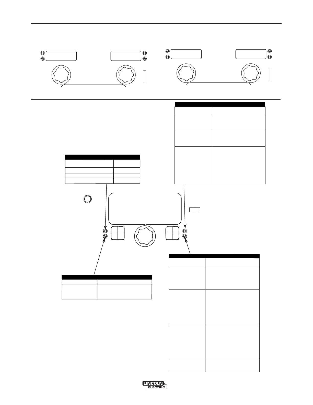
B-9
DISPLAY OPTIONS:
Modes 5 and 6:
OPERATION
Mode 40:
B-9
WFS
MPS
300
25.3
VOLTS
TRIM
USER INTERFACE Operation, Non-Synergic GMAW
(MIG) and FCAW (Flux Cored) Welding.
WELD MODE
PROCESS
GMAW, STANDARD CV
GMAW, POWER MODE
FCAW, STANDARD CV
WELD MODE
5
40
6
WFS
MPS
250
EFFECT / RANGE
Preflow Time
Run-In WFS:
Start Procedure
START OPTIONS
.
DESCRIPTION
Adjusts the
flows
and
Run-In sets the wire feed
speed from the time the trigger
is pulled until an arc is established or 2.5 seconds.
The Start Procedure controls
the WFS and Volts for a specified time at the beginning of
the weld. During the start time,
the machine will ramp up or
down from the Start Procedure
to the preset Welding
Procedure.
time
shielding
after the trigger is
prior to feeding wire.
that
5.7
pulled
VOLTS
TRIM
gas
WELD MODE
ARC CONTROL
EFFECT / RANGE
PINCH
(Soft)-10.0 to
(Crisp)+10.
*Wave Control in Power Wave
ULTIMARC*
Pinch controls the arc characte-
-ristics when short-arc welding.
0
5
STD CV MIG
SET
DESCRIPTION
®
355 and 455 machines.
SETUP
START OPTIONS
END OPTIONS
EFFECT / RANGE
Spot Timer
Crater Procedure
Burnback:
Postflow Time
END OPTIONS
DESCRIPTION
Adjust the time welding will
continue even if the trigger
is still pulled. This option
has no effect in 4-Step
Trigger Mode.
Crater Procedure controls the
WFS and Volts for a specified
time at the end of the weld
after the trigger is released.
During the Crater time, the
machine will ramp up or down
from the Weld Procedure to
the Crater Procedure.
The burnback time is the
amount of time that the weld
output continues after the wire
stops feeding. It prevents the
wire from sticking in the puddle
and prepares the end of the
wire for the next arc start.
Adjusts the time that shielding
gas flows after the welding output turns off.
POWER FEED™ 25M
Page 26
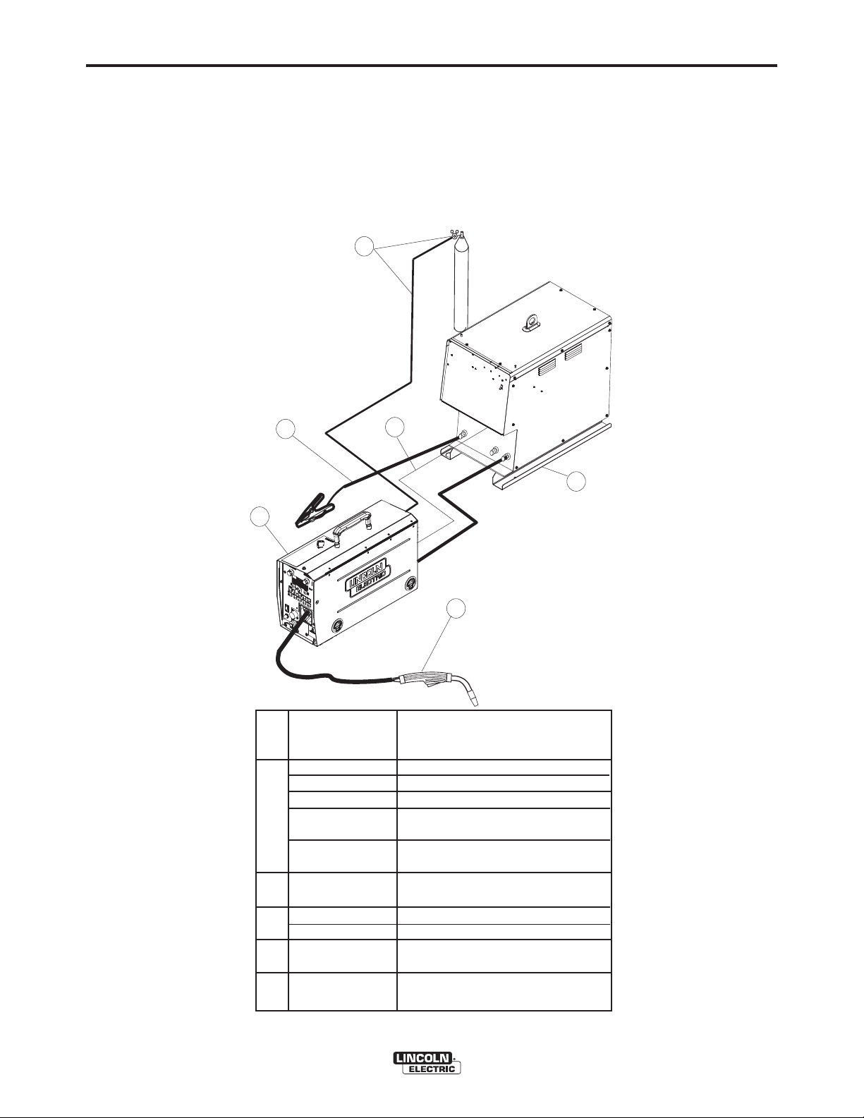
B-10
OPERATION
GMAW (MIG) SYNERGIC WELDING
Synergic welding allows for easy procedure setting.
The WFS and Voltage change together to maintain an
optimal arc length. During synergic welding , when the
WFS (left) knob is rotated, the voltage is adjusted
accordingly to maintain a similar arc length.
Set-up, Physical
FIGURE B.5
6
B-10
4
2
K2202-1 Power Wave 455M
1 K2203-1 Power Wave 455M/STT
K2823-xx Power Wave S350
K2230-1
K2234-1
K2536-4, -5 POWER FEED™ 25M
2 KP1696-xx, Drive Roll Kit, 2 Roll Feeder
KP1697-xx
KP1505-xx, Drive Roll Kit, 4 Roll Feeder
KP1507-xx
3 K1543-xx Digital Control Cable
K2683-xx
4 K1842-xx Weld Power Cable, Lug to Lug
K910-xx Ground Clamp
5 See Magnum
Literature
6 K586-1 Deluxe Regulator for Mixed
3
5
POWER FEED™ 10M, Bench Model
POWER FEED™ 10M Dual, Bench Model
®
MIG gun
Shielding Gases and Gas Hose
1
POWER FEED™ 25M
Page 27
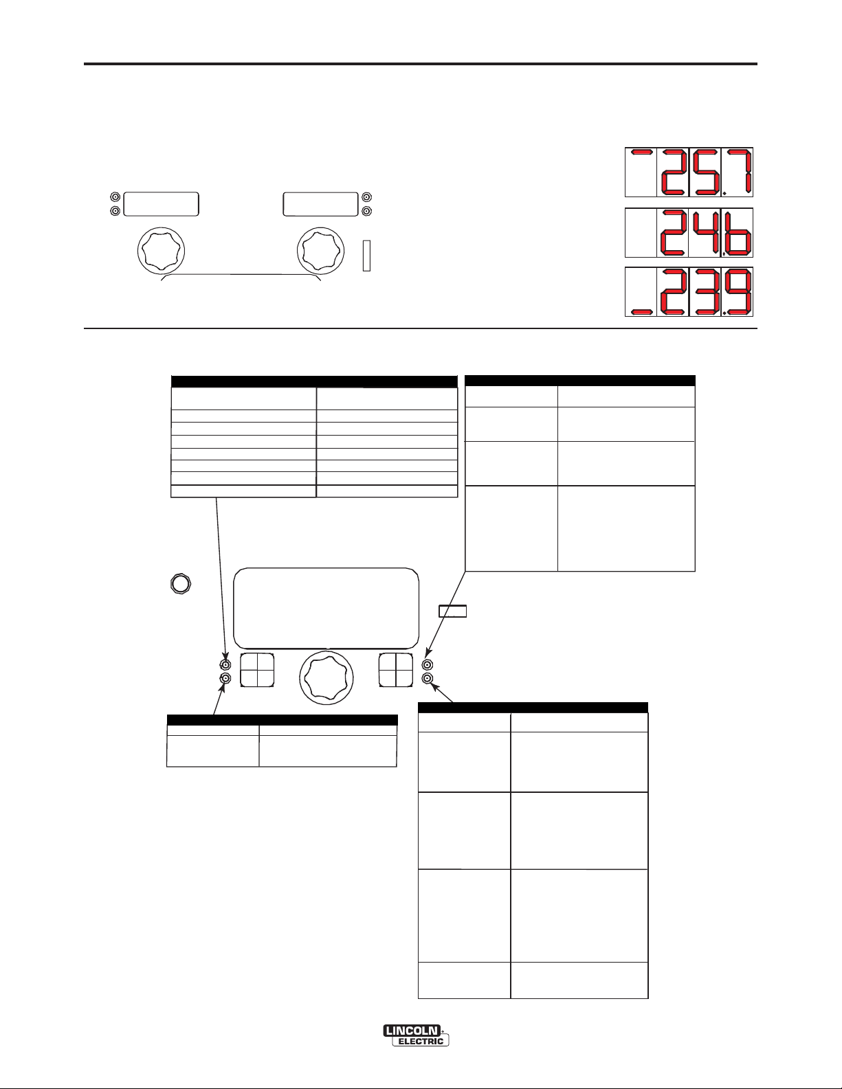
B-11
WFS
AMPS
VOLTS
TRIM
220
26.4
Display Operation
Synergic CV programs feature an ideal voltage best
suited for most procedures. Use this voltage as a
starting point and adjust if needed for personal prefer-
OPERATION
SYNERGIC CV VOLTAGE DISPLAY
When the voltage knob is rotated, the display will
show an upper or lower bar indicating if the voltage is
above or below the ideal voltage.
ences.
• Preset voltage above ideal
voltage. (upper bar displayed)
• Preset voltage at ideal
voltage. (no bar displayed)
• Preset voltage below ideal
voltage. (lower bar displayed)
USER INTERFACE Operation, Synergic GMAW(MIG) Welding
B-11
WELD MODE
ELECTRODE AND GAS
Steel
Steel
Stainless
Stainless
Aluminum 4043
Aluminum 5356
Metal Core --- --- 81 83
CO
2
Ar(Mix)
Ar(Mix)
Ar/He/CO
Ar
Ar
2
WIRE SIZE
0.030 0.035 0.045 0.052
--- 10 20 24
94 11 21 25
61 31 41 --63 33 43 ---
--- 148 71 ---
--- 151 75 ---
Steel
10
.035
CV CO2
WELD MODE
ARC CONTROL
EFFECT / RANGE
PINCH EFFECT
(-10.0 to +10.0)
*Wave Control in Power Wave 355 and 455 machines.
ULTIMARC*
Pinch controls the arc characte-
-ristics when short-arc welding.
SET
DESCRIPTION
®
-
POWER FEED™ 25M
EFFECT / RANGE
Preflow Time
Run-in WFS:
Start Procedure
SETUP
START OPTIONS
END OPTIONS
END OPTIONS
EFFECT / RANGE
Spot Timer
Burnback:
Crater Procedure
Postflow Time
START OPTIONS
DESCRIPTION
Adjust the time welding will
continue even if the trigger
is still pulled. This option
has no effect in 4-Step
Trigger Mode.
The burnback time is the
amount of time that the weld
output continues after the wire
stops feeding. It prevents the
wire from sticking in the puddle
and prepares the end of the
wire for the next arc start.
Crater Procedure controls the
WFS and volts for a specified
time at the end of the weld
after the trigger is released.
During the Crater time, the
machine will ramp up or down
from the Weld Procedure to
the Crater Procedure.
Adjusts the time that shielding
gas flows after the welding output turns off.
DESCRIPTION
Adjusts the time
gas
flows
pulled and
Run-In sets the wire feed
speed from the time the trigger
is pulled until an arc is established or 2.5 seconds.
The Start Procedure controls
the WFS, Volts at a specified
time at the beginning of the
weld. During the start time, the
machine will ramp up or down
from the Start Procedure to the
preset Welding Procedure.
that shielding
after the
prior to feeding.
trigger
is
Page 28
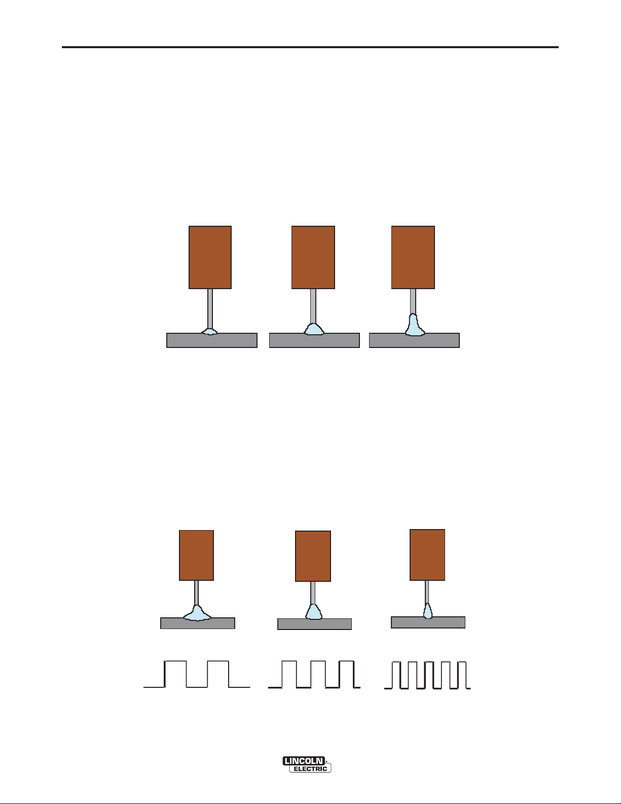
B-12
OPERATION
B-12
STEEL AND STAINLESS SYNERGIC GMAW-P (PULSED MIG) WELDING
Synergic GMAW-P (Pulsed MIG) welding is ideal for low spatter, out of position and reduced heat input applications. During pulse welding, the welding current continuously switches from a low level to a high level and then
back again. Each pulse sends a small droplet of molten metal from the wire to the weld puddle.
Pulse welding controls the arc length with 'Trim' instead of voltage. When trim (arc length) is adjusted, the Power
Wave automatically recalculates the voltage, current and time of each part of the pulse waveform for the best
result. Trim adjusts the arc length and ranges from 0.50 to 1.50. Increasing the trim value increases the arc
length, while decreasing the trim value decreases the arc length.
FIGURE B.6
Trim .50
Arc Length Short
Trim 1.00
Arc Length Medium
Trim 1.50
Arc L ength Long
ULTIMARC*
For steel and stainless pulse modes, UltimArc regulates the focus or shape of the arc. UltimArc values greater
than 0.0 increase the pulse frequency while decreasing the background current, resulting in a tight, stiff arc best
for high speed sheet metal welding. UltimArc values less than 0.0 decrease the pulse frequency while increasing
the background current, for a soft arc good for out-of-position welding.
FIGURE B.7
A rc Con trol -10.0
Low F requency, Wi de
A rc Con trol OFF
Med ium Fr equency and Width
Arc Control +10.0
High Frequency , Fo cu sed
*Wave Control in Power Wave® 355 and 455 machines.
POWER FEED™ 25M
Page 29

B-13
OPERATION
SYNERGIC GMAW-P (PULSED MIG) WELDING
FIGURE B.8
7
!
WARNING
!
WA
L
o
r
e
m
e
li
t
i
,
p
RNING
la
e
s
u
d
o
m
r
d
e
L
ia
e
d
o
t
m
o
r
e
d
lo
e
m
o
n
r
li
lo
o
s
t
ip
n
,
r
i
t
e
la
u
e
s
a
m
u
d
o
m
m
m
r
m
d
a
e
e
i
g
L
e
y
a
d
t
n
o
t
m
o
c
n
a
r
d
l
o
ib
e
o
o
n
n
a
e
m
r
h
lo
o
s
li
l
s
it
n
e
q
e
r
i
i
,
p
e
t
u
c
u
u
la
e
s
a
m
t
a
is
m
e
d
u
m
o
m
m
t
m
m
a
r
ue
d
e
e
g
y
o
e
ia
t
e
d
n
r
d
r
n
c
t
m
a
o
a
a
o
ib
L
d
t
t
lo
in
d
n
a
o
o
n
h
i
r
s
liq
c
p
r
l
o
o
e
e
s
e
i
is
n
d
r
e
m
i
u
c
u
t
e
u
u
c
lit
t
a
is
a
e
m
in
n
m
ip
m
,
m
mo
t
t
g
u
m
la
e
s
a
u
e
e
e
d
u
g
o
y
t
t
d
r
r
m
n
r
a
d
n
c
e
a
a
t
t
i
o
ib
in
e
d
a
d
n
a
t
!
ip
m
o
h
c
s
li
d
i
lo
is
d
q
e
e
L
o
n
u
r
u
c
c
u
o
lo
o
t
n
in
a
s
i
r
e
n
s
r
e
t
it
m
e
g
t
m
u
e
m
u
u
a
m
m
lit
o
e
t
e
m
ip
d
r
m
r
,
a
A
a
e
l
a
e
s
a
g
t
y
t
t
in
d
d
u
o
n
n
c
i
m
c
r
a
p
L
d
o
ib
e
id
i
o
ia
n
s
a
e
d
h
r
u
TT
c
s
liq
t
e
m
!
o
n
i
e
e
d
n
e
m
lo
t
u
c
u
olo
g
lit
n
t
r
u
a
is
ip
o
e
,
t
m
s
n
m
t
A
la
e
r
s
u
i
e
t
u
u
d
o
o
e
er
a
m
m
m
r
d
r
d
m
e
a
m
a
i
a
t
e
a
t
d
e
in
d
g
y
t
VISO DE
m
o
t
ip
n
c
d
ENTION
lo
n
c
i
a
is
o
du
n
o
ib
r
lo
o
n
c
a
P
s
h
n
n
in
s
liq
r
i
e
t
L
u
t
e
e
g
a
u
m
u
o
c
u
m
m
t
a
r
t
i
e
m
s
e
a
m
e
mod
t
e
m
g
u
y
RECAUCION
t
lit
n
e
e
L
n
c
ip
a
,
r
r
o
o
L
ib
a
la
e
s
a
r
n
a
t
t
e
o
h
d
u
in
d
o
s
liq
e
m
m
r
i
r
e
e
c
d
p
l
e
e
it
e
u
id
c
u
i
is
ip
e
a
d
,
t
m
a
i
l
u
e
t
s
c
la
m
o
e
i
s
m
t
m
n
t
in
d
lo
d
u
i
u
o
,
l
t
a
o
e
n
m
g
o
r
e
e
r
p
d
u
lo
e
o
o
L
d
r
r
s
i
t
s
e
d
n
a
a
d
o
r
a
i
r
L
t
e
t
t
u
t
m
u
o
r
i
e
d
n
e
a
d
d
mm
o
l
m
m
ip
o
e
c
m
e
m
o
n
i
re
r
id
is
a
lit
a
lo
t
o
e
e
l
i
t
,
la
e
o
re
e
t
W
ARN
I
N
G
R
E
M
O
3
TE
P
O
WE
R
O
N
O
FF
s
ip
g
u
y
n
d
c
,
m
r
d
t
m
i
n
e
t
l
n
in
u
e
s
a
o
n
c
o
a
a
t
m
d
u
o
o
ib
g
m
l
n
m
u
l
i
m
o
n
r
a
my
o
d
p
h
a
e
t
o
s
li
e
r
i
r
g
L
e
s
a
d
d
q
e
e
t
n
e
na
o
t
s
m
o
u
c
u
u
n
c
d
u
r
d
t
lo
a
i
is
o
ib
e
m d
e
m
t
o
n
m
mm
n
a
e
m
i
r
m
t
h
lo
a
o
u
a
s
liq
l
s
a
it
n
o
e
e
e
e
r
m
m
ip
d
i
,
e
t
g
u
d
r
r
u
c
u
o
l
a
e
o
s
a
a
m
t
a
y
a
is
n
e
m
t
e
L
t
d
u
l
m
o
n
in
d
m
l
o
m
t
m
a
o
o
t
m
a
r
n
u
ip
d
o
e
c
e
r
r s
g
y
r
c
e
o
e
e
ia
id
i
t
e
is
a
n
d
e
b
na
d
r
r
e
m
o
c
n
t
m
u
o
a
c
l
u
m
a
g
n
a
a
h
lit
o
i
ib
i
d
t
n
n
in
t
lo
t
q
in
d
ip
n
m
a
o
,
a
n
t
h
s
g
r
ip
e
s
la
u
l
c
lo
e
s
o
u
iq
e
e
s
e
my
idu
u
u
d
i
me
n
a
t
o
r
s
i
c
u
u
c
e
t
m
u
r
c
i
m
d
t
a
is
e
s
a
e
t
m
n
in
ia
m
m
e
e
m
d
t
m
m
t
t
e
u
g
m
n
t
m
a
o
t
u
e
e
o
er
c
u
d
i
g
l
o
y
a
li
q
t
o
ra
t
b
r
d
o
o
n
n
e
a
L
d
r
n
c
a
lo
h
o
a
t
n
t
o
o
r
ib
s
in
t
d
n
r
r
n
t
it
a
s
i
e
e
e
u
h
a
c
u
p
i
s
liq
n
e
a
id
m
e
m
i
u
d
m
e
a
e
s
m
lit
c
c
u
u
c
c
u
m
i
i
m
a
ip
s
p
i
,
t
in
n
t
a
e
is
d
e
g
y
e
la
e
mo
t
m
s
t
i
g
m
t
n
sc
u
d
u
u
u
t
n
c
e
o
a
u
m
o
o
e
t
ib
er
n
r
r
d
e
d
r
n
a
e
in
a
d
t
ia
h
a
e
d
s
liq
a
L
u
r
t
t
t
tin
t
m
e
o
e
i
g
o
d
n
d
a
u
c
u
lo
r
ip
t
c
e
o
t
a
n
i
d
id
e
r
s
is
e
m
lo
m
o
c
m
t
s
i
u
lit
c
u
n
p
i
r
i
d
in
ip
n
e
t
o
e
e
u
,
i
t
la
a
d
r
r
m
s
e
u
s
g
m
a
u
m
a
d
u
c
o
t
n
m
t
t
a
in
d
m
r
e
i
d
t
e
g
y
n
ip
c
t
u
ia
n
e
d
id
g
n
c
i
s
t
a
m
o
o
ib
t
u
c
d
lo
n
a
n
in
h
o
n
s
liq
r
t
lo
o
g
e
e
u
s
n
u
c
u
r
i
t
e
t
u
t
a
i
e
s
a
m
m
L
m
t
m
m
u
L
m
o
a
e
o
e
e
o
g
re
y
d
r
r
e
t
r
a
na
e
a
n
c
t
t
e
m
m
i
d
o
l
ib
n
it
li
ip
n
a
c
h
t
ip
,
l
s
,
li
id
is
a
i
la
q
e
p
e
e
s
e
u
c
o
u
c
u
d
u
L
o
s
d
n
i
t
a
n
i
m
re
L
o
r
e
s
t
u
d
e
m
g
r
m
t
d
u
o
ia
e
u
e
m
d
e
t
e
m
o
e
ia
t
r
e
m
o
e
t
e
lit
d
r
d
r
lo
a
d
m
ip
d
o
a
n
m
,
l
t
r
t
i
in
lo
o
l
d
o
e
o
s
a
t
l
s
ip
n
,
d
u
l
c
r
o
n
i
l
a
i
o
t
e
u
o
m
i
p
r
is
e
d
d
o
a
e
o
m
r
m
re
s
u
ia
c
d
m
e
n
d
re
m
n
in
s
u
a
t
m
o
e
u
t
d
i
g
d
g
y
m
l
m
t
t
e
o
u
mmy
n
o
n
i
n
c
r
t
a
a
t
a
l
o
a
o
o
i
s
d
b
m
m
n
d
n
r
a
i
g
h
e
t
u
o
s
liq
o
n
a
e
m
e
e
m
l
n
l
n
m
o
u
c
a
o
u
t
m
a
o
t
a
is
r
e
e
r
c
g
i
y
m
a
n
e
t
b
mo
t
s
o
n
u
n
c
l
u
h
a
i
e
i
n
er
o
m
i
t
q
b
m
d
r
e
n
a
s
a
a
h
u
a
s
a
li
t
e
t
m
in
u
m
d
q
e
a
e
g
c
ip
u
c
u
is
c
m
y
n
t
e
a
t
i
id
is
e
s
e
m
m
a
t
m
e
t
u
n
c
u
c
t
in
n
u
o
e
i
o
e
a
r
b
t
o
d
r
g
r
e
a
d
l
u
a
h
ad
iq
n
r a
t
t
t
t
i
t
n
se
e
u
i
ip
c
n
u
d
id
a
is
c
c
i
i
m
u
c
s
p
i
te
d
n
in
m
i
t
s
u
g
t
e
u
u
c
o
n
r
t
e
in
a
d
t
r
t
u
g
tin
a
t
d
c
i
p
i
d
is
u
c
n
i
t
n
u
g
t
W A V E 3 5 5
E R
W
P O
B-13
1
2
4
5
6
K2202-1 Power Wave 455M
1 K2203-1 Power Wave 455M/STT
K2823-xx Power Wave S350
K2230-1 POWER FEED™ 10M, Bench Model
K2234-1
K2536-4, -5 POWER FEED™ 25M
2 KP1696-xx, Drive Roll Kit, 2 Roll Feeder
KP1697-xx
KP1505-xx, Drive Roll Kit, 4 Roll Feeder
KP1507-xx
3 K1543-xx, K2683-xx Digital Control Cable
4 K1796-xx, Coaxial
K960-3 Tweco Style Cam Lock Torch Adapter
5 K910-xx Ground Clamp
6 See Magnum
®
Literature
7 K586-1 Deluxe Regulator for Mixed
POWER FEED™ 10M Dual, Bench Model
Weld Power Cable, Lug to Lug
MIG gun
Shielding Gases and Gas Hose
POWER FEED™ 25M
Page 30

B-14
OPERATION
DISPLAY OPERATION
B-14
WFS
AMPS
220
Operation, Steel and Stainless GMAW-P (Pulsed MIG) Welding
WELD MODE
ELECTRODE AND
Steel(Crisp)
Steel(Soft)
Stainless
Stainless
Stainless
GAS
Ar(Mix)
Ar(Mix)
Ar/
CO
2
Ar/
CO
2
Ar/He/CO
0.030 0.035 0.045 0.052
2
WIRE SIZE
95 12 22 26
---
14 19 28
66 36 46 --62 32 42 ---
--- 34 44 ---
EFFECT / RANGE
Preflow Time
Run-In
Start Procedure
Steel
12
.035
SETUP
Pulse ArMix
WFS:
VOLTS
1.06
START OPTIONS
DESCRIPTION
Adjusts the time that shielding
gas
flows
and
pulled
Run-in sets the wire feed
speed from the time the trigger
is pulled until an arc is established or 2.5 seconds.
The Start Procedure controls
the WFS, Trim at a specified
time at the beginning of the
weld. During the start time, the
machine will ramp up or down
from the Start Procedure to the
preset Welding Procedure.
TRIM
after
the trigger
prior to feeding wire.
is
WELD MODE
ARC CONTROL
SET
ARC
FOCUS
-10.0 (SOFT to
10.0 (STIFF)
*Wave Control in Power Wave 355 and 455 machines.
ULTIMARC*
DESCRIPTION
Arc Focus adjusts the arc from
a wide, soft arc good for out of
position work to a narrow, stiff
arc preferred for faster travel
speeds. The pulse frequency is
lower with a soft arc and higher
with a stiff arc.
®
START OPTIONS
END OPTIONS
EFFECT / RANGE
Spot Timer
Burnback:
Crater Procedure
Postflow Time:
END OPTIONS
FUNCTION
Adjust the time welding will
continue even if the trigger
is still pulled. This option
has no effect in 4-Step
Trigger Mode.
The burnback time is the
amount of time that the weld
output continues after the wire
stops feeding. It prevents the
wire from sticking in the puddle
and prepares the end of the
wire for the next arc start.
Crater Procedure controls the
WFS and Trim for a specified
time at the end of the weld
after the trigger is released.
During the Crater time, the
machine will ramp up or down
from the Weld Procedure to
the Crater Procedure.
Adjusts the time that shielding
gas flows after the welding output turns off.
POWER FEED™ 25M
Page 31

B-15
OPERATION
B-15
ALUMINUM SYNERGIC GMAW-P (PULSED
MIG)AND GMAW-PP (PULSE ON PULSE)
WELDING
The POWER FEED™ 25M and Power Wave welding
power source combine to readily produce top quality
aluminum welds with excellent appearance, little spatter and good bead shape. Push-pull guns are available for consistent feeding when welding a long distance away from the wire feeder.
Pulse-on-Pulse Welding
The Power Wave system offers both traditional pulse
and Pulse-on-Pulse™. Pulse-on-Pulse (GMAW-PP) is
an exclusive waveform for aluminum welding. Use it
to make welds with a "stacked dime" appearance,
similar to GTAW welds.
FIGURE B.9
FIGURE B.11
Frequency Modulation = 10
Narrow weld and ripple spacing, fast travel speed.
The pulsing frequency is adjustable. Changing the frequency modulation (or UltimArc) of the waveform
changes the ripple spacing. Faster travel speeds may
be achieved by using higher values of frequency modulation.
FIGURE B.10
Frequency Modulation = -10
Wide weld and ripple spacing, slow travel speed.
POWER FEED™ 25M
Page 32

B-16
L
o
r
e
m
ip
s
u
m
d
o
lo
r
s
i
t
a
m
e
t
c
o
n
s
e
c
te
tu
e
r
a
d
ip
is
c
i
n
g
e
lit
,
e
d
d
ia
m
n
o
n
u
m
m
y
n
ib
h
e
u
is
m
od
ti
n
c
id
u
n
t u
t
la
o
re
e
t
d
o
lo
r
e
m
a
g
n
a
a
liq
u
a
m
e
r
a
t
L
o
re
m
ip
s
u
m
d
o
lo
r
s
it
a
m
e
t
co
n
s
e
c
te
tu
e
r
a
d
ip
is
c
in
g
e
li
t, e
d
d
ia
m
n
o
n
u
m
m
y
n
ib
h
e
u
i
s
m
o
d
ti
n
c
id
u
n
t u
t
la
o
r
e
e
t
d
o
lo
r
e
m
a
g
n
a
a
li
q
u
a
m
e
r
a
t
L
o
r
e
m
ip
s
um
d
o
lo
r
s
it
a
m
e
t
c
o
n
s
e
c
te
tu
e
r
a
d
ip
i
s
c
in
g
e
lit,
e
d
d
ia
m
n
o
n
u
m
m
y
n
ib
h
e
u
is
m
o
d
ti
n
c
id
u
n
t u
t
la
o
re
e
t
d
o
lo
re
m
a
g
n
a
a
li
q
u
a
m
e
r
at
L
o
r
e
m
ip
s
u
m
d
o
lo
r
s
it
a
m
e
t c
o
n
s
e
c
t
e
tu
e
r
a
d
ip
is
c
in
g
e
li
t, e
d
di
a
m
n
o
n
u
m
m
y
n
ib
h
e
u
i
s
m
o
d
t
in
c
i
d
u
n
t
u
t
la
o
r
e
e
t
d
o
lo
r
e
m
a
g
n
a
a
liq
u
a
m
e
r
a
t
L
o
r
e
m
i
p
s
u
m
d
o
lo
r
s
it
a
m
e
t
c
o
n
s
e
c
te
t
u
e
r
a
d
ip
i
s
c
in
g
e
l
it,
e
d
d
ia
m
n
o
n
u
m
m
y
n
i
b
h
e
u
is
m
o
d
t
in
c
i
d
u
n
t
u
t
la
o
r
e
e
t d
o
l
o
r
e
m
a
g
n
a
a
liq
u
a
m
e
r
a
t
L
o
r
e
m
ip
s
u
m
d
o
lo
r
s
i
t
a
m
e
t c
o
n
s
e
c
te
t
u
e
r
a
d
ip
is
c
i
n
g
e
l
it
,
e
d
d
ia
m
n
o
n
u
m
m
y
n
ib
h
e
u
is
m
o
d
tin
c
id
u
n
t
u
t
la
o
r
e
e
t d
o
lo
r
e
m
a
g
n
a
a
liq
u
a
m
e
ra
t
L
o
re
m
ip
s
u
m
d
o
lo
r s
it
a
m
e
t
c
on
se
c
t
e
tu
e
r
a
d
ip
i
s
c
in
g
e
lit
, e
d
d
ia
m
n
o
n
u
m
m
y
n
i
b
h
e
u
is
m
o
d
tin
c
i
d
u
n
t
u
t
la
o
re
e
t
d
o
lo
r
e
m
a
g
n
a
a
liq
u
a
m
e
r
a
t
L
o
r
e
m
ip
s
u
m
d
o
l
o
r
s
i
t
a
m
e
t
c
o
n
s
e
c
te
tu
er
a
d
i
p
is
c
in
g
e
lit,
e
d
d
ia
m
n
o
n
u
m
m
y
n
ib
h
e
u
i
sm
o
d
ti
n
c
id
u
n
t
u
t
l
a
o
re
e
t
d
o
lo
r
e
m
a
g
n
a
a
liq
u
a
m
e
r
a
t
L
o
re
m
ip
s
u
m
d
o
lo
r
s
it
a
m
et
c
o
n
s
e
c
te
tu
e
r
a
d
ip
i
sc
in
g
e
li
t, e
d
d
ia
m
no
n
u
m
m
y
n
ib
h
e
u
is
m
o
d
tin
ci
d
u
n
t
u
t
l
a
o
r
e
e
t
d
o
lo
re
m
a
g
n
a
a
l
iq
u
a
m
e
r
a
t
L
o
re
m
ip
s
u
m
d
o
lo
r
s
i
t
am
e
t c
o
n
s
e
c
t
e
tu
e
r
a
d
ip
is
c
in
g
e
l
it
,
e
d
d
ia
m
n
o
n
u
m
m
y
n
ib
h
e
u
is
m
o
d
tin
c
id
u
n
t
u
t
la
o
re
e
t
d
o
lo
r
e
m
a
g
n
a
a
liq
u
a
m
e
ra
t
L
o
r
e
m
ip
s
u
m
d
o
l
o
r
si
t
a
m
e
t
c
o
n
s
e
c
te
tu
e
r
a
d
ip
i
sc
in
g
e
lit,
e
d
d
ia
m
n
o
n
u
m
m
y
n
ib
h
e
u
is
m
o
d
tin
c
id
u
n
t
u
t
la
o
r
ee
t
d
o
l
o
r
e
m
a
g
n
a
a
liq
u
a
m
e
r
a
t
L
o
r
e
m
i
p
s
u
m
d
o
lo
r
s
it
a
m
e
t
c
o
n
s
e
c
te
t
u
e
r a
d
i
p
i
s
c
in
g
e
l
it,
e
d
d
ia
m
n
o
n
u
m
m
y
n
i
b
h
e
u
is
m
o
d
tin
c
i
d
u
n
t
u
t
la
o
re
e
t d
o
l
o
r
e
m
a
g
n
a
a
li
q
u
a
m
e
r
a
t
L
o
re
m
ip
s
u
m
d
o
lo
r
s
i
t
a
m
e
t
c
o
n
s
e
c
te
t
u
e
r
a
d
i
p
is
c
in
g
e
lit
,
e
d
d
ia
m
n
o
n
u
m
m
y
n
ib
h
e
u
is
m
o
d
tin
c
id
u
n
t
u
t
l
a
o
r
e
e
t
d
o
lo
re
m
a
g
n
a
a
liq
u
a
m
e
r
a
t
L
o
r
e
m
i
p
s
u
m
d
o
lo
r
s
i
t
a
m
e
t c
o
n
s
e
c
te
t
u
e
r
a
d
i
p
i
s
c
in
g
e
lit
,
e
d
d
ia
m
n
o
n
u
m
m
y
n
ib
h
e
u
is
m
o
d
tin
c
i
d
u
n
t u
t
la
o
r
e
e
t d
o
lo
r
e
m
a
g
n
a
a
li
q
u
a
m
e
r
a
t
L
o
r
e
m
ip
s
u
m
d
o
lo
r
s
i
t
a
m
e
t
c
o
n
s
e
c
te
t
u
e
r
a
d
ip
is
c
i
n
g
e
l
it
, e
d
d
ia
m
n
o
n
u
m
m
y
n
ib
h
e
u
i
s
m
o
d
t
in
c
i
d
u
n
t u
t
la
o
r
e
e
t
d
o
l
o
r
e
m
a
g
n
a
a
liq
u
a
m
e
r
a
t
L
o
r
e
m
ip
s
u
m
d
o
lo
r
s
i
t
a
m
e
t
c
o
n
s
e
c
t
e
t
u
e
r
a
d
ip
is
c
i
n
g
e
lit,
e
d
d
ia
m
n
o
n
u
m
m
y
n
ib
h
e
u
is
m
o
d
ti
n
c
i
d
u
n
t
u
t
la
o
r
e
e
t
d
o
lo
r
e
m
a
g
n
a
a
liq
u
a
m
e
r
a
t
L
o
r
e
m
i
p
s
u
m
d
o
l
o
r
s
it
a
m
e
t
c
o
n
s
e
c
te
t
u
e
r
a
d
ip
is
c
i
n
g
e
li
t, e
d
d
ia
m
n
o
n
u
m
m
y
n
ib
h
e
u
i
s
m
o
d
tin
c
i
d
u
n
t u
t
la
o
r
e
e
t
d
o
lo
r
e
m
a
g
n
a
a
liq
u
a
m
e
r
a
t
L
o
re
m
i
p
s
u
m
d
o
lo
r s
it
a
m
e
t
c
o
n
s
e
c
t
e
t
ue
r
a
d
ip
is
c
in
g
e
li
t
, e
d
d
ia
m
n
o
n
u
m
m
y
n
ib
h
e
u
is
m
o
d
tin
c
i
d
u
n
t
u
t
la
o
re
e
t d
o
l
o
r
e
m
a
g
n
a
a
l
iq
u
a
m
e
r
a
t
L
o
re
m
ip
s
u
m
d
o
lo
r s
it
am
e
t
c
o
n
se
c
t
e
tu
e
r
a
d
ip
is
c
in
g
e
lit
, e
d
d
ia
m
n
o
n
u
m
m
y
n
ib
h
e
u
is
m
o
d
ti
n
c
id
u
n
t
u
t
la
o
r
e
e
t d
o
lo
re
m
a
g
n
a
a
liq
u
a
m
e
ra
t
OPERATION
B-16
ALUMINUM GMAW-P AND GMAW-PP WELDING
Set-up, Physical
Keep the electrode protected by using a spool cover or a feeder which encloses the spool. Use a heater kit with
the feeder if available. If high humidity or condensation is present, store the wire in the original packaging when
not welding.
FIGURE B.14
7
!
WARNING
!
W
AR
Lo
r
e
m
e
ip
li
t
su
, e
NING
m
lao
d
d
d
olo
i
r
a
e
m
e
r
t d
sit a
L
n
or
on
o
e
lo
u
m
m
r
m
e
e
e
ip
m
m
t
li
co
t
su
y n
, e
ag
m
nse
d
ib
n
la
d
d
a
h e
o
ct
o
i
a
r
a
e
lor
liq
et
m
u
e
ism
u
t
u
d
n
si
e
am
L
o
t
r
o
or
a
od
n
a
lor
!
u
er
e
m
d
m
m
tin
e
ip
e
a
e
m
m
t c
iscin
t
i
cid
p
lit, e
y n
a
sum
o
gn
un
n
i
g
s
b
lao
d
a
ecte
t
h
A
do
d
ut
a
euism
ia
r
li
e
lo
q
m
tu
e
ua
r
t d
n
e
TT
sit a
r
m
o
od
a
o
n
e
l
dip
o
um
tincid
m
L
ra
r
e
o
et
i
t
sc
m
r
m
e
con
y n
i
!
m
a
n
un
e
g
g
ip
A
ib
n
t u
secte
l
it
a
E
sum
h
, e
aliq
t
e
la
d
u
tue
d
d
i
VISO
sm
u
o
o
ia
a
r
N
e
r
l
m
o
m
od
e
a
r
e
t d
n
s
dip
tin
r
i
o
t
a
o
a
n
i
t
s
lor
cid
um
P
ci
m
TION
e
n
un
et co
L
m
m
g
o
t u
y n
r
ag
e
m
n
t
R
ib
n
se
ipsu
elit, e
a
h
ct
e
a
Lo
liqu
e
u
m
tu
ism
r
la
d
e
E
d
e
am
m
d
o
DE
r
o
ia
od
a
r
ipsu
e
e
l
er
o
m
lit, e
dipiscin
et
L
r
tin
o
sit a
a
no
d
C
r
m
t
cid
e
la
d
o
n
m
d
l
o
dia
u
o
e
u
m
olor
r
m
ip
re
g
n
e
lit,
e
m
t
m
m
su
e
ut
t
t
n
AUCIO
sit a
con
ed
y
L
m
a
do
la
o
o
n
g
d
r
n
ib
d
na
e
o
l
se
o
u
o
ia
m
m
r
h
r
m
e
lo
a
ct
e
e
m
e
ip
elit,
e
m
r
l
e
t
m
u
t
iq
n
con
si
t
su
y
ism
d
u
a
u
on
t
olo
e
er
n
g
a
m
a
la
d
ib
n
m
um
se
o
m
a
a
r
d
dia
h
d
o
e
e
d
e
a
ct
olo
eu
tin
r
m
i
t co
r
m
eet
p
l
e
a
m
iq
y nib
iscing
tu
a
r
t
cidun
ism
n
sit a
u
g
d
n
e
a
L
n
o
se
r
L
o
m
or
a
o
nu
h
o
lo
a
a
d
ct
e
e
e
m
t u
r
d
r
tin
m
e
m
liq
e
i
e
r
uism
e
p
m
at
e
t
m
m
t
ip
t
iscin
u
u
cidu
ipsu
elit, e
li
co
y
e
am
a
t
su
r
, ed
nib
gn
o
a
n
g
d
m
n
er
se
d
m
a
la
t u
la
h
d
tincidu
d
ip
d
a
cte
e
d
a
or
d
or
o
ia
e
lor
m
e
t d
n
Lo
o
o
n
rem
lo
u
r
m
e
e
m
m
l
ip
i
t
a
,
g
e
s
n
l
a
u
a
d
o
m
a
d
re
liq
d
ia
e
L
o
m
t
o
lo
d
re
n
r
ol
m
o
sit
e
o
n
l
r
it,
i
u
e
p
a
m
su
m
e
m
l
a
m
d
e
o
m
a
y
t
d
r
g
e
co
i
d
n
n
a
et
o
a
ib
m
n
l
o
a
h
d
se
n
r
li
o
eu
o
qu
si
c
lo
n
te
t
re
ism
u
am
a
t
m
m
m
m
o
e
e
a
d
y
t
r
gn
a
co
t
n
i
t
n
a
i
b
n
a
h
sect
l
i
e
q
u
u
e
i
a
sm
t
m
u
e
o
era
r
d
a
t
di
i
t
n
pi
c
i
d
u
n
t
u
t
N
L
isci
o
i
t
t
liqu
a
uism
o
e
lor
m
tu
re
et
n
n
e
s
a
m
g
nt
sit a
do
r
m
i
o
o
t
ipsu
e
a
am
n
d
e
ut
l
lit
d
o
um
t
ipiscing
r
, e
r
i
m
a
e
n
et co
m
t
m
cidu
m
e
la
d
t
d
d
y n
co
a
o
y n
o
ia
g
re
nse
n
lor
i
na
n
m
t
b
ibh
e
se
ut
h e
t
n
sit a
a
cte
do
ct
o
l
eu
u
iq
n
etu
t
lo
ism
u
um
u
ism
m
u
e
r
a
e
e
am
r
e
m
o
a
m
r
t
m
od
co
d
ad
d
y n
e
L
tin
a
er
ip
r
tin
or
g
a
i
n
p
iscin
a
ibh
n
t
se
cid
e
iscing
t
a
cidu
m
a
ct
eu
e
un
g
i
liq
e
p
lit, e
n
tu
t u
ism
sum
u
t u
e
a
t
r
la
m
d
t
od
a
do
d
e
o
d
tin
ia
r
ip
r
e
lo
a
m
iscin
e
t
cid
r
t d
n
sit am
o
u
Lo
o
g
n
n
l
o
um
t u
r
e
r
e
m
et
t
m
u
m
ipsu
e
con
y n
e
l
a
it,
g
r
i
n
e
se
b
a
m
a
la
d
h
d
aliqu
cte
d
d
e
o
i
olo
ia
p
u
r
ci
e
tu
i
isci
m
sm
et
d
r
e
a
no
sit a
r
u
m
do
od
a
n
n
e
n
dip
lo
tin
t
g
um
r
m
a
re
u
i
t
e
s
cid
t
m
ci
t
m
con
y n
n
un
a
g
g
t u
i
na
se
b
L
h
t
a
o
ct
e
r
liq
et
e
u
sc
m
ism
u
u
e
e
a
ips
i
r
m
lit,
n
o
a
d
g
e
u
d
ed
t
m
ip
r
L
la
in
a
iscin
d
d
o
t
cidun
o
olo
re
ia
L
r
e
o
m
e
g
m
re
r
e
t d
sit a
t u
n
m
li
o
i
e
olor
t
t
ip
psu
nu
,
li
m
e
t
su
l
m
,
a
e m
e
e
d
m
m
o
m
t co
la
d
d
y
re
d
d
a
or
i
n
d
g
o
i
nse
am
a
e
L
ib
n
e
lor
ol
m
a
t
e
o
h
a
t
n
o
cte
e
d
re
si
do
n
liqu
r
on
o
uism
t
am
tu
m
o
si
lo
l
e
o
u
n
e
a
l
r
m
t
r
it,
r
e
i
m
u
e
o
a
e
psu
a
m
m
t co
d
m
e
d
m
e
t
y nib
m
la
a
ipiscing
r
i
m
d
a
n
gn
e
nse
o
m
a
t
cidu
y
t
d
r
g
a
h e
e
co
a
i
cte
d
n
n
a
e
n
l
ol
a
i
uism
i
m
t
q
b
t
n
tue
u
u
o
a
h
d
se
t
a
n
r
li
o
r
m
o
e
a
o
q
si
ct
lo
d
u
d
n
e
u
t
t
e
ipiscin
re
r
ism
um
in
a
a
a
t
t
cid
m
u
m
m
e
m
o
u
e
e
r
a
g
n
d
y
t
r
a
t ut
gn
a
co
t
di
ni
in
t
a
p
b
n
c
i
h
a
i
se
sc
d
l
iq
u
e
ct
i
n
n
u
ua
e
t
g
i
sm
t
u
m
u
t
e
o
era
r
d
a
t
d
i
t
n
i
p
c
i
i
sc
d
u
i
n
n
t
g
u
t
V E 3 5 5
P O W E R W A
W
A
R
NI
NG
R
E
MO
T
E
P
O
W
E
R
ON
O
F
F
1
3
4
2
5
K2368-1 Power Wave®355M
®
1 K2202-1 Power Wave
K2203-1 Power Wave
K2230-1 POWER FEED™ 10M, Bench Model
Requires K1634-1 Spool cover
K2234-1
2
POWER FEED™ 10M Dual, Bench Model
Requires K1634-1 Spool cover
K2536-4, -5 POWER FEED™ 25M
KP1695-xx Drive Roll Kit, 2 Roll Feeder
KP1507-xx Drive Roll Kit, 4 Roll Feeder
3 K1543-xx, K2683-xx Digital Control Cable
4 K1796-xx, K2593-xx Coaxial
5 K910-xx Ground Clamp
6 K2447-xx Python Plus Gun, Air cooled
Deluxe Regulator for Mixed
7 K586-1 Shielding Gases
Shielding Gas Hose
455M
®
455M/STT
Weld Power Cable, Lug to Lug
6
POWER FEED™ 25M
Page 33

B-17
OPERATION
Display Operation
B-17
WFS
AMPS
220
1.06
VOLTS
TRIM
USER INTERFACE Operation, Aluminum GMAW-P (Pulsed MIG) and GMAW-PP (Pulse on Pulse) Welding
WELD MODES
ELECTRODE AND GAS
ALUMINUM 4043
ALUMINUM 4043
ALUMINUM 5356
ALUMINUM 5356
Ar
Ar
Ar
Ar
72
WIRE SIZE
0.035 3/64 1/16
149 72 74
98 99 100
152 76 78
101 102 103
Aluminum
3/64
SETUP
START OPTIONS
EFFECT / RANGE
Preflow Time
WFS:
Run-In
Start Procedure
DESCRIPTION
Adjusts the time that shielding
gas
flows
pulled
and
Run-in sets the wire feed
speed from the time the trigger
is pulled until an arc is established or 2.5 seconds.
The Start Procedure controls
the WFS. Trim at a specified
time at the beginning of the
weld. During the start time, the
machine will ramp up or down
from the Start Procedure to the
preset Welding Procedure.
the trigger is
after
prior to feeding wire.
4043 Pulse Ar
WELD MODE
ARC CONTROL
SET
PULSE
FREQUENCY:
(Low)-10.0 to
(High)+10.0
PULSE-ON-PULSE
FREQ.MODULATION
(Low)-10.0 to
(High)+10.0
*Wave Control in Power Wave 355 and 455 machines.
ULTIMARC*
DESCRIPTION
For Pulse
changes the pulsing frequency.
When the frequency changes,
the Power Wave system automatically adjusts the background current to maintain a
similar heat input into the weld.
Low frequencies give more control over the puddle and high
frequencies minimize spatter.
For Pulse -On-Pulse modes,
Arc controls changes the frequency modulation. The freque-
-ncy modulation controls the
spacing of the ripples in the
weld. Use low values for slow
travel speeds and wide welds,
and high values for fast travel
speeds and narrower welds.
modes, Arc Control
®
START OPTIONS
END OPTIONS
Postflow Time:
EFFECT / RANGE
END OPTIONS
Spot Timer
Burnback:
Crater Procedure
FUNCTION
Adjust the time welding will
continue even if the trigger
is still pulled. This option
has no effect in 4-Step
Trigger Mode.
The burnback time is the
amount of time that the weld
output continues after the wire
stops feeding. It prevents the
wire from sticking in the puddle
and prepares the end of the
wire for the next arc start.
Crater Procedure controls the
WFS and Trim for a specified
time at the end of the weld
after the trigger is released.
During the Crater time, the
machine will ramp up or down
from the Weld Procedure to
the Crater Procedure.
Adjusts the time that shielding
gas flows after the welding output turns off.
POWER FEED™ 25M
Page 34

B-18
OPERATION
B-18
GMAW-STT™ WELDING
Surface Tension Transfer, or STT™ welding, is a
break-through process offered exclusively by the
Lincoln Electric Company. STT™ is a low heat, low
spatter process created with Waveform Control
Technology™. STT™ is the process of choice for
open root welding, welding on thin materials or welding on parts with poor fit-up. Low spatter, even when
using 100% CO
in gas and part clean-up.
Several sets of STT™ weld modes are available.
• Non synergic modes provide individual control of
peak current, background current and tail-out.
Some modes also provide for adjustment of hot
start.
• Synergic STT™ modes keep the arc characteristics
the same when the wire feed speed is changed.
Note that STT™ is available only with specially
equipped Power Wave power sources, like the Power
Wave 455M/STT or the Power Wave S350 + STT
Module.
2 shielding gas, results in cost savings
FIGURE B.15
8
3
1
2
4
For best results:
• Attach the work sense lead as close as possible to
the welding arc.
• Use only solid steel, stainless steel or silicon bronze
electrodes.
1 K2203-1 Power Wave 455M/STT
2 K2536-4, -5 POWER FEED™ 25M
3 K1543-xx Digital Control Cable
4
5 K910-xx Ground Clamp
6 K940-xx Sense Lead Kit
7 See Magnum
8 K586-1 Deluxe Regulator for Mixed
6
5
l
K2823-xx + K2902-1
K2230-1
K2234-1
7
Power S350 + STT Module
POWER FEED™ 10M, Bench Model
POWER FEED™ 10M Dual, Bench Mode
KP1696-xx Drive Roll Kit, 2 Roll Drive
KP1505-xx Drive Roll Kit, 4 Roll Drive
K2683-xx Heavy Duty ArcLink Control Cable
K1796-xx, K2593-xx
Coaxial Weld Power Cable, Lug to Lug
K960-3 Tweco Style Cam Lock Torch Adapter
®
MIG Gun
Literature
Shielding Gases and Gas Hose
POWER FEED™ 25M
Page 35

B-19
OPERATION
GMAW-STT™
Waveform Control Technology™ maximizes the
ability to modify the arc for the perfect weld. When
STT™ welding, the parameters to control are:
• Wire Feed Speed - sets the deposition rate.
• Peak Current - controls the arc length.
• Background Current - regulates the bead contour.
• Tail-out - provides additional power in the arc.
USER INTERFACE Operation, GMAW-STT™ Welding
WFS
AMPS
220
----
B-19
VOLTS
TRIM
STEEL
109
.035”
STT
WELD MODE
ARC CONTROL
SET
ULTIMARC*
EFFECT / RANGE
PEAK CURRENT
agitation.
BACKGROUND
CURRENT
TAIL OUT
(
STT ll MODES
ONLY)
*Wave Control in Power Wave 355 and 455 machines.
without the molten
Often this results in
DESCRIPTION
Peak Current acts similar to an
control. Peak Current
promotes
and
current levels will cause
momentarily
set too high, globular transfer
Setting it too low
and wire
adjust for minimum spatter and
Background Current controls
heat input in the
Tail out provides additional
too large.
heat input without increasing
Note that
current
to be reduced.
while increasing arc length. If
stubbing.
Increase as necessary to add
as tail out increases, the peak
and/or background current
sets the arc length
good fusion.
®
the arc to broaden
may cause instability
practice is to
Best
weld.
droplet becoming
faster travel speeds.
pinch
arc
Higher
may occur.
puddle
overall
the
power
arc length.
may need
SETUP
START OPTIONS
END OPTIONS
peak
EFFECT / RANGE
Preflow Time
Run-In
WFS:
Start Procedure
EFFECT / RANGE
Crater Procedure
Burnback:
Postflow Time:
START OPTIONS
Adjusts the time that shielding
gas
pulled and
Run-in sets the wire feed
speed from the time the trigger
is pulled until an arc is established or 2.5 seconds.
The Start Procedure is not
commonly used with STT
procedures.
END OPTIONS
Crater is not commonly used
in STT weld procedures.
The burnback time is the
amount of time that the weld
output continues after the wire
stops feeding. It prevents the
wire from sticking in the puddle
and prepares the end of the
wire for the next arc start.
Adjusts the time that shielding
gas flows after the welding output turns off.
FUNCTION
flows
after
prior to feeding wire.
FUNCTION
the trigger
is
POWER FEED™ 25M
Page 36

B-20
OPERATION
PEAK CURRENT (Figure B.16)
Peak current controls the arc length, which also
affects the shape of the root. When using 100% CO
the peak current will be higher than when welding with
blended shielded gases. A longer arc length is
required with CO
2 to reduce spatter.
FIGURE B.16
B-20
2,
Peak
Current
Too Low
Background
Current
Too Low
Peak
Current
Optimum
BACKGROUND CURRENT (Figure B.17)
Background current adjusts the overall heat input into
the weld. Changing the background current changes
the shape of the back bead. 100% CO
background current than when welding with blended
shielding gases.
FIGURE B.17
Background
Current
Optimum
2 requires less
Peak
Current
Too High
Background
Current
Too High
TAILOUT
Tailout provides additional heat into the weld without
increasing the arc length or the droplet size. Higher
tailout values improve wetting and may give faster
travel speeds.
POWER FEED™ 25M
Page 37

B-21
OPERATION
GTAW (TIG) WELDING
The POWER FEED™ / Power Wave system is excellent for Touch Start TIG welding.
The system supports TIG torches with or without gas
control valves. TIG torches with gas control valves
connect directly to the gas flow regulator. For TIG
torches without gas control valves, connect the output
gas hose on the wire feeder to the TIG torch gas
hose.
The wire feeder gas solenoid may be enabled or disabled by parameter P.8 in the set-up menu found in
this operations section.
B-21
Touch Start TIG
Weld Sequence
TIG torches without
built-in Gas Valves.
TIG torches with
built-in Gas Valves.
No Foot / Hand Amptrol
1. Adjust the arc amperage with the left knob
on the display panel.
2. Turn the right knob on the display panel
until the Output Control is ON. Gas will
start to flow.
3. Touch the tungsten to the work piece.
4. Lift the tungsten to create an arc and weld.
5. Stop welding by turning the Output Control
to OFF, or by pulling away the tungsten
from the work.
6. Gas flow will continue for a short time and
then shut-off.
1. Adjust the arc amperage with the left knob
on the display panel.
2. Turn the right knob on the display panel
until the Output Control is ON.
3. Open the gas valve on the TIG torch.
4. Touch the tungsten to the work piece.
5. Lift the tungsten to create an arc and weld.
6. Stop welding by turning the Output Control
to OFF, or by pulling away the tungsten
from the work.
7. Close the gas valve on the TIG torch.
With Foot / Hand Amptrol
1. Adjust the maximum arc amperage with
the left knob on the display panel.
2. Touch the tungsten to the work piece.
3. Press the foot pedal or slide the hand
amptrol a slight amount. Gas will start to
flow.
4. Lift the tungsten to create an arc.
5. Regulate the arc current with the foot
pedal or hand amptrol.
6. Stop welding by releasing the foot pedal
or hand amptrol, or by pulling the tungsten away from the work.
7. Gas will continue for a short time and
then shut-off.
1. Adjust the maximum arc amperage with
the left knob on the display panel.
2. Touch the tungsten to the work piece.
3. Press the foot pedal or slide the hand
amptrol a slight amount.
4. Open the gas valve on the TIG torch.
5. Lift the tungsten to create an arc.
6. Regulate the arc current with the foot
pedal or hand amptrol.
7. Stop welding by releasing the foot pedal
or hand amptrol, or by pulling the tungsten away from the work.
8. Close the gas valve on the TIG torch.
POWER FEED™ 25M
Page 38

B-22
Lo
r
e
m
i
p
s
u
m
d
o
lo
r
s
it
a
m
e
t c
o
n
s
e
c
te
tu
er
a
d
ip
is
c
i
n
g
e
li
t,
e
d
d
ia
m
n
o
n
u
m
m
y
n
ib
h
e
u
is
m
od
ti
n
c
id
u
n
t
u
t
la
o
re
e
t d
o
lo
r
e
m
a
g
n
a
a
l
iq
ua
m
e
r
a
t
Lo
r
em
ip
su
m
do
l
o
r
s
it
a
m
e
t
co
n
s
e
c
te
t
u
er
a
d
ip
is
c
in
g
e
lit
,
e
d
d
i
a
m
n
o
n
u
m
m
y
n
ib
h
e
u
is
m
o
d
t
in
ci
d
u
n
t
u
t
lao
re
e
t d
o
lor
e
m
a
g
n
a
a
l
iq
u
a
m
e
r
at
Lo
re
m
ip
s
um
d
o
lor
sit
a
m
e
t c
o
n
s
e
c
te
tu
e
r
a
d
i
p
is
cin
g
e
l
it
,
e
d
d
ia
m
n
o
n
u
m
m
y
n
ib
h
e
u
ism
o
d
ti
n
c
id
u
n
t
u
t
l
a
o
re
e
t
d
o
lor
e
m
a
g
n
a
a
liq
u
a
m
e
r
a
t
L
o
rem
ip
s
u
m
d
o
l
or
s
it
a
m
e
t c
o
n
s
e
c
te
t
ue
r a
d
i
p
isc
in
g
e
li
t,
e
d
d
ia
m
n
o
n
u
m
m
y n
ib
h
eu
is
m
o
d
ti
n
c
id
u
n
t
u
t
la
o
re
e
t
d
o
lo
r
e
m
a
g
n
a
a
liq
ua
m
e
r
a
t
Lo
r
em
ip
su
m
d
o
lo
r
sit
a
m
e
t
co
n
s
e
c
t
etu
e
r
a
d
ip
i
s
c
in
g
e
lit,
e
d d
ia
m
no
n
u
m
m
y
n
ib
h
e
u
is
m
o
d
t
in
c
i
du
n
t u
t
l
a
o
ree
t d
o
l
o
re
m
ag
na
a
liq
u
am
e
ra
t
L
o
re
m
ip
s
u
m
d
ol
o
r s
it
a
m
e
t
co
ns
ec
te
tu
er
ad
i
p
is
c
in
g
e
l
it
,
e
d
d
ia
m
n
o
n
u
m
m
y
n
ib
h
e
u
is
m
o
d
t
in
c
id
u
nt
u
t
l
a
o
re
e
t
d
o
lo
r
e
m
a
g
n
a
a
l
iq
u
a
m
e
r
a
t
L
o
re
m
ip
s
um
do
l
o
r
s
i
t
a
m
e
t c
o
n
s
e
c
te
t
u
e
r a
d
ip
is
cin
g
el
it
,
e
d
d
i
a
m
n
on
u
m
m
y
n
ib
h
e
u
is
m
o
d
ti
n
c
id
u
n
t
u
t
la
o
re
e
t
d
o
lo
re
m
a
g
n
a
a
li
qu
a
m
e
ra
t
L
o
r
e
m
i
ps
um
do
lo
r s
it
a
m
e
t
c
o
n
se
c
te
t
u
e
r
a
d
i
p
is
cin
g
e
li
t, e
d
d
i
a
m
n
o
n
u
m
m
y
n
ib
h
e
uis
m
o
d
ti
n
c
id
u
n
t
u
t
l
ao
r
e
e
t
do
lo
re
m
a
g
n
a
aliq
u
a
m
e
ra
t
Lo
r
e
m
i
ps
um
d
o
lo
r
s
it
a
m
e
t c
o
n
s
e
c
te
tu
e
r
a
d
ipi
s
c
i
ng
e
li
t,
e
d
d
ia
m
n
o
n
u
m
m
y
ni
b
h
e
u
i
s
m
od
tin
c
id
u
n
t u
t
la
o
re
e
t
d
o
lor
e
m
a
gn
a
a
li
q
u
a
m
e
r
at
Lo
re
m
ip
s
u
m
d
o
l
o
r
s
it
a
m
e
t
co
ns
e
c
t
e
tu
e
r
a
d
ip
is
c
in
g
e
lit,
e
d d
ia
m
no
n
u
m
m
y
n
ib
h
e
u
ism
o
d
t
in
c
id
u
n
t
u
t
la
o
re
e
t d
o
l
ore
m
a
g
na
a
liq
u
a
m
er
a
t
L
o
re
m
ip
s
u
m
d
o
l
o
r s
it
am
e
t
c
o
n
s
e
c
te
tu
e
r
a
d
ip
i
s
c
in
g
e
lit,
e
d
d
ia
m
no
n
um
m
y
n
ib
h
e
u
is
m
o
d
tin
c
id
u
n
t u
t
la
o
re
e
t
d
ol
o
re
m
a
g
na
a
liq
u
a
m
e
ra
t
L
o
re
m
ip
s
u
m
d
o
l
o
r
s
it
a
m
e
t c
on
s
e
c
te
t
ue
r
a
d
i
p
i
s
c
in
g
e
lit,
e
d
d
ia
m
n
o
n
u
m
m
y
n
ibh
e
u
is
m
o
d
t
in
c
i
du
n
t
u
t
la
or
e
e
t
d
o
lo
r
e
m
a
g
n
a
a
liqu
a
m
e
ra
t
L
or
e
m
i
p
su
m
d
olo
r s
it
am
e
t
c
o
n
se
c
te
t
u
e
r
a
d
ip
is
ci
n
g
e
li
t
,
ed
d
i
am
n
o
n
u
m
m
y
ni
bh
e
u
ism
o
d
ti
nc
idu
nt
ut
l
a
o
re
e
t
do
lo
re
m
ag
n
a
al
i
q
ua
m
e
ra
t
L
orem
i
ps
um
do
lo
r
sit am
e
t c
onse
cte
tu
er a
dipisc
in
g
e
lit, e
d diam
n
on
um
my n
ibh
e
ui
sm
o
d tin
cid
unt ut
laore
et d
olo
re
m
ag
na aliquam
e
rat
Lor
em
ips
um
do
lo
r
sit am
e
t c
ons
e
c
te
tue
r ad
ip
is
cin
g
elit, e
d dia
m n
onu
m
m
y n
ib
h euism
o
d tin
cid
u
nt u
t
lao
reet
dol
ore
m
ag
n
a aliqu
am
e
ra
t
Lo
rem
ip
sum
do
l
or s
it
am
et conse
c
tetuer
adip
is
cin
g
elit, e
d diam
n
onum
m
y n
ibh
euis
m
od t
in
cidunt u
t
laoree
t d
olore
m
agna
aliqua
m
e
r
at
Lore
m ips
um
d
ol
o
r
si
t a
m
e
t c
on
se
ct
etue
r adipiscin
g
elit, ed
diam
n
o
nu
m
m
y n
ibh
eu
ism
od tinc
id
unt u
t
lao
reet
dolore
m
a
gna
a
liqua
m
era
t
L
o
rem
ip
s
u
m
d
o
l
or
s
it
a
m
e
t
co
n
s
ec
te
tu
e
r a
d
i
p
is
c
in
g
e
lit,
e
d
di
a
m
n
o
n
u
m
m
y
n
ib
h
e
u
is
m
o
d
t
in
c
id
u
n
t u
t
la
o
r
e
e
t
d
o
lo
re
m
a
g
na
a
liq
u
a
m
e
r
at
L
o
r
e
m
i
p
su
m
d
olo
r
s
it
a
m
e
t
c
o
n
s
e
cte
tu
e
r
ad
i
p
is
cin
g
e
lit,
ed
d
i
am
no
nu
m
m
y
n
i
b
h
e
u
i
sm
o
d
t
in
c
id
u
n
t
u
t
la
or
e
e
t
d
o
lo
re
m
a
g
n
a
a
liq
u
am
er
a
t
OPERATION
B-22
GTAW (TIG)WELDING (Figure B.17a)
WARNING
Do not connect a high frequency arc starting kit to
the Power Feed / Power Wave system.
FIGURE B.17a
8
!
WARN
!
WARN
IN
L
o
G
r
e
m
e
i
p
l
i
t
s
,
u
e
m
d
l
a
d
d
o
o
i
r
a
e
l
o
m
e
r
ING
t
L
d
n
s
o
i
o
t
o
r
n
a
e
l
o
u
m
m
r
m
e
e
e
i
m
p
t
l
m
i
t
s
c
y
,
a
u
o
e
n
g
m
n
d
i
n
l
s
b
a
d
d
a
e
h
o
c
o
i
e
a
re
a
t
l
l
e
o
m
u
i
e
q
t
r
i
u
t
s
u
n
s
e
d
m
a
L
i
o
t
r a
o
m
o
o
n
a
l
!
r
o
d
u
e
m
d
e
r
m
m
e
t
i
ra
e
p
i
n
m
e
t
i
m
t
i
s
c
p
l
c
y
c
i
i
a
t
d
s
o
i
,
n
g
n
u
e
u
n
i
n
g
m
n
s
b
d
a
l
e
t
ATTE
h
a
u
d
d
c
o
a
e
t
o
i
t
r
l
a
e
u
i
e
l
q
o
m
t
i
e
u
s
u
r
t
n
e
m
a
s
d
r
m
i
o
o
t
o
a
n
d
a
l
d
e
o
u
m
t
i
L
r
re
m
p
i
a
n
o
e
i
t
s
c
m
re
t
m
c
i
d
c
y
i
!
m
a
n
u
o
n
g
g
n
n
e
i
A
i
n
p
s
t
b
l
i
a
t
e
s
u
h
,
u
c
t
a
e
e
t
m
l
e
d
u
i
l
q
a
t
d
i
V
u
d
s
u
o
e
o
m
i
a
r
a
N
e
r
l
m
o
m
o
e
a
r
d
t
d
e
d
n
s
t
i
ra
i
o
p
i
ISO D
t
o
n
n
i
t
a
s
l
ci
o
P
u
c
m
TION
d
r
m
i
e
n
u
e
L
m
g
n
t
m
o
t
c
y
re
a
o
u
n
g
m
n
RECA
t
i
n
s
b
e
a
e
i
h
p
l
c
i
a
t
s
e
L
t
,
l
u
e
u
o
i
e
q
m
t
i
r
u
d
s
u
l
e
a
e
m
a
m
d
d
o
r
m
o
i
o
r
e
a
a
e
i
l
d
e
p
o
l
m
d
i
e
L
t
s
r
t
i
r
,
t
o
p
i
u
a
d
n
s
n
e
re
i
m
t
i
s
o
c
d
t
o
l
c
i
n
a
m
d
a
l
d
i
d
o
u
o
n
u
m
e
o
i
r
m
r
i
g
a
n
e
p
E
l
e
l
e
i
o
m
t
t
s
m
e
t
m
,
r
u
u
t
c
e
L
y
n
s
t
m
a
d
o
d
o
i
o
l
n
g
t
o
a
n
r
n
d
i
d
n
a
e
l
o
s
b
o
u
o
i
a
m
m
e
r
h
a
re
m
e
l
a
c
o
m
e
e
e
e
U
t
i
m
r
l
p
e
t
l
m
u
t
i
i
q
n
s
t
s
t
c
y
i
d
,
u
a
s
u
i
o
u
o
t
o
e
e
n
m
g
a
n
m
n
a
l
d
r
i
n
o
m
l
u
s
b
o
a
m
a
a
re
m
e
d
d
h
d
o
d
e
e
C
c
o
i
a
re
a
m
e
ti
i
t
ra
t
m
l
p
l
e
o
m
n
u
i
co
e
y
q
i
t
r
a
t
s
c
i
u
t
s
u
n
d
g
c
n
s
i
n
e
d
m
a
L
i
i
i
n
o
se
n
b
t
r
L
o
u
m
o
o
a
n
g
h
a
o
l
n
a
r
ION
o
a
d
u
c
e
m
re
t
d
e
e
r
m
t
m
u
e
l
t
i
e
r
u
e
i
p
i
m
a
q
e
n
t
m
t
i
t
i
m
u
s
t
u
i
s
c
e
p
l
c
y
i
e
m
i
c
i
a
p
a
l
t
d
s
o
n
i
r
i
,
m
t
su
g
n
u
o
u
n
,
e
a
i
n
g
m
d
n
s
b
e
d
d
e
m
a
l
e
t
h
a
d
ti
i
l
ra
p
d
d
c
u
a
o
a
n
e
d
L
d
i
o
t
i
t
o
t
r
sc
l
c
a
e
u
o
i
o
i
e
l
r
q
a
i
o
m
t
e
d
i
l
re
e
u
s
o
i
u
m
r
n
e
u
t
e
m
r
a
d
m
n
s
g
t
n
L
r
m
n
s
i
o
o
d
t
t
o
e
a
i
o
o
i
n
d
t
o
u
a
p
l
l
d
e
n
o
i
u
r
a
l
t
t
m
su
t
i
o
r
u
,
re
e
m
p
i
m
a
n
re
m
e
e
i
m
m
t
s
c
m
e
e
d
t
m
l
m
c
i
a
t
m
d
c
y
l
i
i
d
d
a
o
co
n
i
o
u
y
t
a
o
i
n
p
g
r
g
a
n
n
,
n
e
g
l
i
n
e
n
o
m
s
s
t
b
i
e
n
l
a
se
b
e
r s
h
u
u
ao
t
a
d
h
c
n
t
a
d
e
m
c
t
i
o
a
l
e
e
t
o
u
t
i
d
re
n
l
q
e
t
u
a
i
l
d
i
q
u
o
s
u
u
i
t
i
m
u
a
s
u
e
r
m
m
e
a
L
e
o
e
m
a
r
e
m
m
t
o
o
m
r
m
t
lo
a
m
o
d
a
d
re
c
d
y
e
d
e
L
a
n
d
o
r
t
i
o
ra
p
o
i
n
g
s
t
i
e
n
n
r
m
o
p
i
i
r
l
i
a
n
n
t
s
s
c
b
o
e
i
n
i
t
a
s
c
c
e
i
l
h
m
t
d
re
it
c
i
i
i
um
ct
d
n
a
p
u
a
i
e
,
e
n
u
g
i
l
e
n
e
u
p
i
l
s
l
m
g
q
n
i
m
tu
t
t
i
s
um
a
s
u
,
t
m
u
d
u
e
m
e
a
e
u
o
a
t
m
d
r
m
d
t
t
y
o
l
r
g
a
a
e
d
n
d
c
d
i
o
do
d
n
e
a
o
i
e
o
r
t
i
a
ra
a
p
i
i
e
l
m
n
o
b
m
t
n
i
e
l
a
t
s
c
r
o
h
do
s
t
ci
i
n
s
d
no
r
d
e
l
n
i
o
u
i
L
e
t
o
qu
s
g
c
n
l
n
o
a
l
o
ui
o
n
u
i
t
t
re
m
t
e
r
r
m
u
a
u
a
e
s
e
m
e
t
t
m
m
m
m
u
t
m
m
e
m
i
c
y
e
p
l
a
m
e
o
o
i
n
t
s
e
g
r
,
a
n
d
u
a
i
n
y
t
e
r
s
b
g
m
a
a
e
d
h
c
l
ti
d
na
a
n
c
d
t
a
d
o
n
e
o
t
i
ib
l
e
o
i
pi
u
i
re
n
a
c
q
t
l
i
o
u
m
h
al
s
i
u
s
e
s
d
r
e
m
a
e
e
t
c
i
n
r
s
u
m
d
q
o
c
i
i
o
a
t
n
n
u
o
d
u
te
n
d
e
a
l
g
t
i
o
u
t
i
a
ra
s
m
p
i
r
n
tu
m
u
e
m
i
m
t
e
s
c
t
m
c
i
t
m
e
d
od
e
i
c
y
n
u
r
a
o
g
n
n
g
ra
n
a
t
i
n
s
b
t
d
u
a
in
L
t
e
h
t
i
o
c
e
a
p
c
t
re
l
e
u
i
i
i
q
s
t
d
m
i
u
s
u
c
u
e
m
e
a
i
i
r
p
nt
l
ng
m
o
i
t
s
a
,
d
u
d
u
e
e
m
t
i
r
L
d
p
i
a
l
n
t
a
i
o
t
s
d
c
d
o
c
i
o
re
i
L
d
re
a
i
l
n
o
u
o
m
e
e
g
m
r
n
r
e
t
t
n
s
m
d
l
u
i
o
i
t
i
o
t,
t
e
p
n
a
i
l
p
o
l
u
s
i
m
e
t
s
r
l
m
,
a
um
e
u
e
d
e
m
m
o
t
m
d
l
c
a
d
y
r
a
d
d
o
e
o
i
n
d
g
o
i
n
a
r
a
et
Lo
i
n
e
l
s
o
b
o
m
m
a
e
e
h
r
l
d
t
o
c
re
a
n
s
n
e
t
d
l
r
e
i
o
ol
u
i
t
o
q
e
t
m
n
o
i
s
a
u
l
s
u
o
o
u
m
nu
e
m
i
a
l
r
i
m
t
re
i
r
e
m
e
t,
o
ps
a
m
a
t
m
d
m
m
l
d
e
m
c
e
t
y
a
i
r
a
um
o
p
i
m
d
a
n
n
g
e
n
i
o
ag
t
s
c
i
n
s
b
t c
y
d
c
i
r
a
e
d
h
i
e
n
n
i
c
u
d
n
a
a
e
e
g
t
o
n
l
o
e
a
i
u
i
m
t
q
b
t d
n
t
i
l
u
u
s
u
o
h
a
s
n
e
m
t
a
r
e
l
o
r
m
i
e
o
o
q
a
s
c
l
d
o
u
d
nu
e
u
it
te
t
i
r
ra
i
p
a
i
a
s
e
n
t
i
t
m
s
m
m
ci
u
m
c
m
d
e
i
m
o
n
u
e
e
r
a
g
n
d
y
t c
r
a
g
t
a
n
u
ti
di
na
t
t
o
n
i
p
bh
n
c
i
al
i
s
s
du
e
c
i
eu
q
c
i
n
n
u
te
g
t u
i
a
s
tu
m
m
t
e
o
e
r
d
r
a
a
ti
d
t
n
i
p
c
i
i
s
d
c
u
i
n
n
t u
g
t
3 5 5
V E
R W A
W E
W
A
R
N
I
N
G
R
E
M
O
T
E
O
N
O
F
F
3
4
2
6
P O
P
O
W
E
R
1
5
7
Display Operation
Maximum
Amperage
WFS
AMPS
220
OFF
USER INTERFACE Operation, GTAW (Touch Start
TIG) Welding.
WELD MODE
TOUCH START 3
MODE
START OPTIONS
No Arc starting options are
active for Touch Start TIG.
3
SETUP
Touch Start TIG
WELD MODE
ARC CONTROL
ULTIMARC
No Arc Controls are active
for Touch Start TIG.
EFFECT DESCRIPTION
Crater Time Function
0 To 10 seconds
SET
END OPTIONS
During the Crater time, the
machine will ramp up or down
from the Weld Procedure to
the Crater Procedure.
START OPTIONS
END OPTIONS
VOLTS
TRIM
K2202-1 Power Wave® 455M
1 K2203-1 Power Wave® 455M/STT
K2823-xx Power Wave® S350
K2230-1 POWER FEED™ 10M, Bench Model (requires K2320-1 connector kit)
2 K2234-1 POWER FEED™ 10M Dual, Bench Model (requires K2320-1 connector kit)
K2536-4, -5 POWER FEED™ 25M
3 K1543-xx ArcLink Control Cable
K2683-xx Heavy Duty ArcLink Control Cable
4 K1842-xx Weld Power Cable, Lug to Lug
5 K910-xx Ground Clamp
6 K1782-xx, K1783-xx PTA-17, PTA-26 TIG torch (shown with valve)
7 K870-xx Foot Amptrol
8 3100211 Harris Argon Flow Regulator
WELD MODE SEARCHING
The Weld Mode Search feature allows the selection of
a welding mode based on certain criteria (wire size,
process type, etc.).
SEARCHING FOR A WELD MODE
During the search process, pressing the right pushbutton typically acts as a “next” button and the left pushbutton typically acts as a “back” button.
Rotate the control knob then press the right pushbutton to select relevant welding details such as welding
process, wire type, wire size, etc.
To search for a mode, turn the control knob until
“Weld Mode Search” is displayed. This will appear in
between the highest and the lowest weld mode numbers.
Once “Weld Mode Search” is displayed, pressing the
right pushbutton labeled “Begin” will start the search
process.
When the final selection is made, the Feeder will automatically change to the weld mode found by the Weld
Mode Search process.
Earlier products may not have this feature. To activate this feature, a software update may be needed
from www.powerwavesoftware.com
POWER FEED™ 25M
Page 39

B-23
OPERATION
B-23
SETUP MENU FEATURES
The Setup Menu gives access to the Setup Configuration. Stored in the setup configuration are user parameters
that generally only need to be set at installation. The parameters are grouped as shown in the following table.
PARAMETER
P.1 through P.99
P.101 through P.199
P.501 through P.599
1. To access the set-up menu, press the right and left
2. After changing a parameter it is necessary to press
3. To exit the set-up menu at any time, press the
DEFINITION
Unsecured Parameters (always adjustable)
Diagnostic Parameters (always read only)
Secured Parameters (only accessible through a p.c. or palm application)
SET-UP FEATURES MENU
(See Figure B.17b)
buttons of the user interface panel simultaneously.
Note that the set-up menu cannot be accessed if
the system is welding, or if there is a fault (The status LED is not solid green).
Change the value of the blinking parameter by rotating the SET knob.
the Right hand button to save the new setting.
Pressing the Left button will cancel the change.
Right and Left buttons of the MSP4 panel simultaneously. Alternately, 1 minute of inactivity will also
exit the set-up menu.
Status LED
FIGURE B.17b - SETUP MENU
Left
button
SET Knob
Right
button
Main display
POWER FEED™ 25M
Page 40

B-24
OPERATION
USER DEFINED PARAMETERS
Parameter Definition
P.0 Exit Setup Menu
This option is used to exit the setup menu. When P.0 is displayed, press the Left Button to exit
the setup menu.
P.1 Wire Feed Speed Units
This option selects which units to use for displaying wire feed speed.
English = inches/minute wire feed speed units (default).
Metric = meters/minute wire feed speed units.
P.2 Arc Display Mode
This option selects what value will be shown on the upper left display while welding.
Amps = The left display shows Amperage while welding (default).
WFS = The left display shows Wire Feed Speed while welding.
P.3 Display Options
This setup parameter was previously named "Display Energy"
If the previous software revision had this parameter set to display energy, that selection will
remain.
B-24
This option selects the information displayed on the alphanumeric displays while welding. Not all
P.3 selections will be available on all machines. In order for each selection to be included in the
list, the power source must support that feature. A software update of the power source may be
needed to include the features.
Standard Display = The lower displays will continue to show preset information during and after
a weld (default).
Show Energy = Energy is displayed, along with time in HH:MM:SS format.
Show Weld Score = The accumulative weld score result is shown
P.4 Recall Memory with Trigger
This option allows a memory to be recalled by quickly pulling and releasing the gun trigger. To
recall a memory, quickly pull and release the trigger the number of times that correspond to the
memory number. For example, to recall memory 3, quickly pull and release the trigger 3 times.
To recall memory 1, quickly pull and release the trigger the number of user memories plus 1.
Memories cannot be recalled while the system is welding.
Disabled = The gun trigger cannot be used to recall user memories (default).
Enabled = The gun trigger can be used to recall user memories.
POWER FEED™ 25M
Page 41

B-25
OPERATION
USER DEFINED PARAMETERS
Parameter Definition
P.5 Procedure Change Method
This option selects how remote procedure selection (A/B) will be made. For some products the selected
procedure can be changed locally at the user interface by pressing the 'A-Gun-B' button. Other products
do not have this button and must use a Cross-switch gun or wire into the procedure select input. The following methods can be used to remotely change the selected procedure:
LF45 and C300CE:
Quick Trigger = Allows switching between Procedure A and procedure B while welding with 2-stroke
mode. The Cross-switch gun or remote control is required. To operate:
• Select "Procedure A/B" in P.25 to set up parameters for A and B procedures.
• Start the weld by pulling the gun trigger. The system will weld with procedure A settings.
• While welding, quickly release and then pull the gun trigger. The system will switch to procedure B settings. Repeat to switch back to procedure A settings. The procedure can be changed as many times as
needed during the weld.
• Release the trigger to stop welding. When the next weld is made, the system will start again with procedure A.
IntegralTrigProc = Allows switching between Procedure A and procedure B while welding with 4-stroke
mode. When in 2-step, the system operates identical to the External Switch selection. To operate in 4step:
• Select "Procedure A/B" in P.25 to set up parameters for A and B procedures.
• Start the weld by pulling the gun trigger. The system will weld with procedure A settings.
• While welding, quickly release and then pull the gun trigger. The system will switch to procedure B settings.
• Release the trigger to stop welding. When the next weld is made, the system will start again with procedure A.
B-25
External Switch = Dual Procedure selection may only be performed by the Cross-switch gun or remote
control (default).
All Other Products:
External Switch = Dual Procedure selection may only be performed at the memory panel or an external
switch (e.g. K683).
Quick Trigger = The selected procedure can be changed remotely by releasing and re-pulling the trigger
quickly while welding. This feature is disabled in 4-Step trigger mode. The external procedure switch is
disabled. To operate:
• Select "GUN" on the memory panel (for products that have an 'A-Gun-B' button).
• Start the weld by pulling the gun trigger. The system will weld with procedure A settings.
• While welding, quickly release then pull the gun trigger once. The system will switch to procedure B settings. Repeat to switch back to procedure A settings. The procedure can be changed as many times as
needed during the weld.
• Release the trigger to stop welding. The system will automatically return to procedure A settings.
IntegralTrigProc = When using a Magnum DS dual-schedule gun (or similar) that incorporates a procedure switch in the gun trigger mechanism. While welding in 2-step, machine operation is identical to the
"External Switch" selection. When welding in 4-step, additional logic prevents procedure A from being reselected when the trigger is released at step 2 of the 4-step weld sequence. The machine will always
operate in 2-step if a weld is made exclusively in procedure A, regardless of the 2/4 step switch position
(this is intended to simplify tack welding when using a dual-schedule gun in 4-step)
.
POWER FEED™ 25M
Page 42

B-26
OPERATION
USER DEFINED PARAMETERS
Parameter Definition
P.7 Gun Offset Adjustment
This option adjusts the wire feed speed calibration of the pull motor of a push-pull gun.
This should only be performed when other possible corrections do not solve any pushpull feeding problems. An rpm meter is required to perform the pull gun motor offset
calibration. To perform the calibration procedure do the following:
1. Release the pressure arm on both the pull and push wire drives.
2. Set the wire feed speed to 200 ipm.
3. Remove wire from the pull wire drive.
4. Hold an rpm meter to the drive roll in the pull gun.
5. Pull the trigger on the push-pull gun.
6. Measure the rpm of the pull motor. The rpm should be between 115 and 125 rpm. If
necessary, decrease the calibration setting to slow the pull motor, or increase the
calibration setting to speed up the motor.
The calibration range is -30 to +30, with 0 as the default value.
Note: The range was changed to -90 to +90 for the PF25M in WD software S28539-3.
Default value remains at 0.
P.8 TIG Gas Control
This option allows control over which gas solenoid actuates while TIG welding.
"Valve (manual)" = No MIG solenoid will actuate while TIG welding, gas flow is manually controlled by an external valve.
"Solenoid (auto) = This selection only applicable to PWC300. The MIG solenoid will
turn on and off automatically while TIG welding.
"Feeder Solenoid" = No applicable to PWC300. The internal (feeder) MIG solenoid will
turn on and off automatically while TIG welding.
"Pwr Src Solenoid" = Not applicable to PWC300. Any gas solenoid connected to the
power source will turn on and off automatically while TIG welding. This selection will
not appear in the list if the power source does not support a gas solenoid.
B-26
Notes: Preflow is not available while TIG welding. Postflow is available - the same
postflow time will be used in MIG and TIG. When machine output on/off is controlled via the upper right knob, gas flow will not start until the tungsten touches
the work. Gas flow will continue when the arc is broken until the Postflow time
expires. When machine output on/off is controlled via an arc start switch or foot
Amptrol, gas will begin flowing when the output is turned on and will continue
flowing until the output is turned off and the Postflow time expires.
P.9 Crater Delay
This option is used to skip the Crater sequence when making short tack welds. If the
trigger is released before the timer expires, Crater will be bypassed and the weld will
end. If the trigger is released after the timer expires, the Crater sequence will function
normally (if enabled).
POWER FEED™ 25M
Page 43

B-27
OPERATION
USER DEFINED PARAMETERS
Parameter Definition
P.14 Reset Consumable Weight
Use this option to reset the initial weight of the consumable package. Press the Right Button to reset the
consumable weight. This option will only appear with systems using Production Monitoring.
P.16 Push-Pull Gun Knob Behavior
This option determines how the potentiometer on the Push/Pull torch will behave.
• Gun Pot Enabled = The welding wire feed speed is always controlled by the potentiometer on the pushpull gun (default). The left front panel knob is only used to adjust Start and Crater wire feed speed.
• Gun Pot Disabled = The wire feed speed is always controlled by the left front panel knob. This setting is
useful when the operator wishes to have wire feed speed settings recalled from memories and not have
the potentiometer "overwrite" the setting.
• Gun Pot Proc A = When in procedure A, the welding wire feed speed is controlled by the potentiometer
on the push-pull gun. When in procedure B, the welding wire feed speed is controlled by the left front
panel knob. This setting allows a fixed wire feed speed to be selected in procedure B and not have the
potentiometer "overwrite" the setting when the procedure changes.
P.17 Remote Control Type
This setup parameter was previously named "Spool/Push-Pull"
B-27
This option selects the type of analog remote control being used. Digital remote control devices (those
with a digital display) are configured automatically. Not all P.17 selections will be available on all
machines. When P.17 is used to configure the remote control to function in a specific process, the remote
will be ignored in other processes. For example, if P.17 = TIG Amp Control, the remote control will only
function when TIG welding - the remote will be ignored in other processes (MIG, stick and gouge). If P.17
is set to Spool Gun or Push-Pull Gun then set to All Mode Remote, the machine will remember prior value
of P.17 and will operate a Spool Gun or Push-Pull Gun, depending on the prior value of P.17.
Spool Gun = Use this setting while MIG welding with a spool gun that uses a potentiometer used for wire
feed speed control (this setting is backward compatible with "P.17 Gun Selection" = Standard/Spool).
Push-Pull Gun = Use this setting wile MIG welding with a push-pull gun that uses a potentiometer for
wire feed speed control (this setting is backward compatible with "P.17 Gun Selection" = PushPull).
TIG Amp Control = Use this setting while TIG welding with a foot or hand current control device
(Amptrol). While TIG welding, the upper left knob on the User Interface sets the maximum current
obtained when the TIG amp control is at its maximum setting.
Stick/Gouge Rem. = Use this setting while stick welding or gouging with a remote output control device.
While stick welding, the upper left knob on the User Interface sets the maximum current obtained when
the stick remote is at itʼs maximum setting. While gouging, the upper left knob is disabled and the gouging
current is set on the remote control.
All Mode Remote = This setting allows the remote control to function in all weld modes which is how
most machines with 6-pin and 7-pin remote control connections operate. This setting was provided so that
customers with a mix of Lincoln Electric equipment can have consistent remote control behavior across all
of their equipment. (N. American default)
Joystick MIG Gun = Use this setting while MIG welding with a push MIG gun with a joystick control.
Stick, TIG and gouge welding currents are set at the User Interface. (European default)
POWER FEED™ 25M
Page 44

B-28
OPERATION
USER DEFINED PARAMETERS
Parameter Definition
P.18 Wire Drive Gear Ratio
This option selects the Wire Drive Gear Ratio that will be used. The possible selectable values
are read from the Wire Drive on startup. For semi-automatic systems, if the feedhead board
has dip switches, this option does not appear in the menu. Gear ratio can be selected using the
dip switches.
Note: Changing this value will cause the system to reset.
P.20 Display Trim as Volts Option
This option determines how trim is displayed.
False = The trim is displayed in the format defined in the weld set (default).
True = All trim values are displayed as a voltage.
Note: This option may not be available on all machines. The power source must support this
functionality, or this option will not appear in the menu.
P.22 Arc Start/Loss Error Time
This option can be used to optionally shut off output if an arc is not established, or is lost for a
specified amount of time. Error 269 will be displayed if the machine times out. If the value is set
to OFF, machine output will not be turned off if an arc is not established nor will output be
turned off if an arc is lost. The trigger can be used to hot feed the wire (default). If a value is
set, the machine output will shut off if an arc is not established within the specified amount of
time after the trigger is pulled or if the trigger remains pulled after an arc is lost. This is disabled
while welding in Stick, TIG or Gouge. To prevent nuisance errors, set Arc Start/Loss Error Time
to an appropriate value after considering all welding parameters (run-in wire feed speed, weld
wire feed speed, electrical stick out, etc). To prevent subsequent changes to Arc Start/Loss
Error Time, the setup menu should be locked out by setting Preference Lock = Yes using the
Power Wave Manager software.
B-28
P.24 Push Pull Type
Allows operator to choose the Prince option if welding with a Prince Push Pull gun. This gun
requires unique settings to run at the correct WFS.
Note: This option may not be available on all machines. The wire drive must support this functionality, or this option will not appear in the menu.
P.27 Language Select
Selects which language will be displayed on the User Interface.
English (Default) Italiano
Deutsch Francais
Polski Espanol
P.28 Display Workpoint as Amps Option
This option determines how workpoint is displayed.
False = The workpoint is displayed in the format defined in the weld set (default).
True = All workpoint values are displayed as an amperage.
Note: This option may not be available on all machines. The power source must support this
functionality, or this option will not appear in the menu.
POWER FEED™ 25M
Page 45

B-29
OPERATION
USER DEFINED PARAMETERS
Parameter Definition
P.80 Sense From Studs
Use this option for diagnostic purposes only. When power is cycled, this option is automatically
reset to False.
False = Voltage sensing is automatically determined by the selected weld mode and other
machine settings (default).
True = Voltage sensing is forced to "studs".
P.81 Electrode Polarity
Used in place of DIP switches for configuration of the electrode sense lead. This option allows selection of the electrode voltage sense polarity. Most GMAW welding procedures use Electrode Positive
welding. Most GTAW and some inner shield procedures use Electrode Negative welding.
Positive Electrode Welding (default).
Negative Electrode Welding.
This option will only appear in the menu if the feedhead board does not have a dip switch to set the
polarity, and the power source does not support auto-hardware sense lead configuration. If this
option does not apper in the menu, voltage sense polarity can be selected using the dip switches.
B-29
P.82 Voltage Sense Display
Allows viewing of Voltage Sense Lead Selection to aid in troubleshooting. The configuration is
displayed as a text string on the lower display whenever the output is enabled. This parameter
is not saved on a power cycle, but will be reset to False.
P.99 Show Test Modes
Most power sources contain weld modes used for calibration and test purposes. By default, the
machine does not include test weld modes in the list of weld modes that are available to the
operator. To manually select a test weld mode, set this option to "Yes". When the power source
is turned off and back on again, the test modes will no longer appear in the mode list. Test weld
modes typically require the machine output to be connected to a grid load and cannot be used
for welding.
P.100 View Diagnostics
Diagnostics are only used for servicing or troubleshooting the Power Wave system. Select
"Yes" to access the diagnostic options in the menu. Additional parameters will now appear in
the setup menu (P.101, P.102, etc).
P.101 View Event Logs
Used for viewing all the system event logs. Press the Right Button to enter the option. Rotate
Control Knob to select the desired event log to read. Press the Right Button again to enter the
selected log. Rotating the Control Knob will scroll through the event log, displaying the log
index number, event code and some other data. Press the Left Button to back out to select
another log. Press the Left Button again to exit this option.
P.102 View Fatal Logs
Used for viewing all the system fatal logs. Press the Right Button to enter the option. Rotate
Control Knob to select the desired fatal log to read. Press the Right Button again to enter that
log. Rotating the Control Knob will scroll through the log, displaying the log index number and
fatal code. Press the Left Button to back out to select another log. Press the Left Button again
to exit this option.
POWER FEED™ 25M
Page 46

B-30
OPERATION
USER DEFINED PARAMETERS
Parameter Definition
P.103 View Software Version Information
Used for viewing the software versions for each board in the system. Press the Right Button to
enter the option. Rotate Control Knob to select the desired board to read. Press the Right
Button again to read the firmware version. Press the Left Button to back out to select another
board. Rotate the Control Knob to select another board, or press the Left Button to exit this
option.
P.104 View Hardware Version Information
Used for viewing the hardware version for each board in the system. Press the Right Button to
enter the option. Rotate Control Knob to select the desired board to read. Press the Right
Button again to read the hardware version. Press the Left Button to back out to select another
board. Press the Left Button again to exit this option.
P.105 View Welding Software Information
Used for viewing the Weld Set in the Power Source. Press the Right Button to read the Weld
Set version. Press the Left Button to back out and exit this option.
P.106 View Ethernet IP Address
Used for viewing the IP address of Ethernet compatible equipment. Press the Right Button to
read the IP Address. Press the Left Button to back out and exit this option. The IP address cannot be changed using this option.
B-30
P.107 View Power Source Protocol
Used for viewing the type of power source the feeder is connected to. Press the Right Button to
identify the power source as either LincNet or ArcLink. Press the Left Button to back out and
exit this option.
P.350 User Interface Group Selection
Used to differentiate multiple PF25M feeders connected to the same power source. Each independent feeder must have a unique selection in order to resolve error 18 problems.
P.500 View Lockout Parameters
Originally used to prevent inadvertent changes of secure setup parameters, P.500 was previously used as a gateway to these parameters. Presently, this option does not exist in any setup
menu.
P.501 Encoder Lockout
Locks one or both of the upper knobs (encoders), preventing the operator from changing wire
feed speed, amps, volts or trim. The function of each upper knob depends on the selected weld
mode. When a constant current weld mode is selected (e.g. Stick, TIG, Gouge), the upper right
knob will always function as an on/off switch. This parameter can only be accessed using
Power Wave Manager software.
P.502 Memory Change Lockout
Determines if the memories can be overwritten with new contents.
• No = Memories can be saved and limits can be configured (default).
• Yes = Memories cannot be changed - saving is prohibited and limits cannot be re-configured.
This parameter can only be accessed using Power Wave Manager.
POWER FEED™ 25M
Page 47

B-31
OPERATION
USER DEFINED PARAMETERS
Parameter Definition
P.503 Memory Button Disable
Disables the specified memory button(s). When a memory is disabled, welding procedures cannot be restored from or saved to that memory. If an attempt is made to save or restore a disabled memory, a message will be displayed on the lower display indicating the memory number
is disabled. In multi-head systems, this parameter disables the same memory buttons on both
feed heads. This parameter can only be accessed using Power Wave Manager software.
P.504 Mode Select Panel Lock
Selects between several Mode Select Panel lockout preferences. When a Mode Select Panel
selection is locked and an attempt is made to change that parameter, a message will be displayed on the lower display indicating the parameter is locked.
• All MSP Options Unlocked = All adjustable parameters on the Mode Select Panel are
unlocked.
• All MSP Options Locked = All knobs and buttons on the Mode Select Panel are locked.
• Start & End Options Locked = The Start and End parameters on the Mode Select Panel are
locked, all others are unlocked.
• Weld Mode Option Locked = The weld mode cannot be changed from the Mode Select Panel,
all others Mode Select Panel settings are unlocked.
• Wave Control Options Locked = The Wave Control parameters on the Mode Select Panel are
locked, all others are unlocked.
• Start, End, Wave Options Locked = The Start, End and Wave Control parameters on the
Mode Select Panel are locked, all others are unlocked.
• Start, End, Mode Options Locked = The Start, End and Weld Mode Select parameters on the
Mode Select Panel are locked, all others are unlocked.
This parameter can only be accessed using Power Wave Manager software.
B-31
P.505 Setup Menu Lock
Determines if the setup parameters can be modified by the operator without entering a passcode.
• No = The operator can change any set menu parameter without first entering the passcode
even if the passcode is non-zero (default).
• Yes = The operator must enter the passcode (if the passcode is non-zero) in order to change
any setup menu parameters.
This parameter can only be accessed using Power Wave Manager.
P.506 Set User Interface Passcode
Prevents unauthorized changes to the equipment. The default passcode is zero which allows
full access. A nonzero passcode will prevent unauthorized:
• changes to memory limits, saving to memory (if P.502 = Yes), changes to setup parameters (if
P.505 = Yes).
This parameter can only be accessed using Power Wave Manager software.
P.509 User Interface Master Lockout
Locks all user interface controls, preventing the operator from making any changes. This parameter can only be accessed using Power Wave Manager software.
POWER FEED™ 25M
Page 48

B-32
OPERATION
B-32
DUAL PROCEDURE/MEMORY PANEL
OPERATION
The Dual Procedure/Memory Panel performs three
functions:
• Weld procedure selection
• Memory save and recall
• Limits setting
There are two procedure memories (A and B) and
eight user memories (1-8).
Procedure Memory vs. User Memory
Procedure memory is used while welding. Changes to
the weld procedure (WFS, voltage, UltimArc™
Controll, etc.) immediately change the contents inside
the selected procedure memory.
PROCEDURE
MEMORY
A
GUN B
1
USER
MEMORIES
ARE COPIED TO
PROCEDURE
MEMORY
M
2
3
(8) USER
MEMORIES
M
4
USER MEMORIES
Recall a memory with memory buttons
To recall a user a memory, press one of the six user
memory buttons. The memory is recalled when the
button is released. Do not hold the button for more
than two seconds when recalling a user memory.
Recall a memory with the gun trigger
If desired, memories 1 through 8 can be recalled with
the gun trigger. For example, to recall memory 3,
quickly pull and release the gun trigger 3 times without
welding. To recall memory 1, quickly pull and release
the gun trigger 9 times without welding. Note: the wire
feeder is factory set with this feature disabled. Use
the SETUP menu and change P.4 to enable memory
recall with the gun trigger.
Note that memories may be locked with P.C. application software to prevent accidental overwrite of the
memories. If an attempt is made to save a memory
when memory saving is locked, the message
"Memory save is Disabled!" will appear briefly in the
MSP4 display.
RECALL:
PRESS
1 SECOND
SAVE:
PRESS
2 SECONDS
5
6
7
8
User memories work by copying the weld procedure
from one of the eight memories into either the “A ” or
“B” procedure. Weld procedures are saved into the
memories only when the operator chooses.
Using Procedure Memories
Procedure memories can be selected by choosing
either "A" or "B" procedure directly with the memory
panel, or by selecting "GUN" and using a dual procedure gun to select between procedure "A" and "B".
When selecting procedures with the gun switch, "A" or
"B" will flash to show which procedure is active.
PRESS
TO SELECT
PROCEDURE
A
GUN B
1
M
2
3
M
4
A
GUN B
M
1
5
2
6
3
7
M
4
8
5
6
7
8
POWER FEED™ 25M
Page 49

B-33
OPERATION
B-33
LIMITS
Limits allow the welder to adjust the welding procedure only within a defined range.
Each user memory may have a different set of limits.
For example, memory 1 may limit the WFS to 200
through 300 in/min, and memory 2 may limit the WFS
to 275 through 310 in/min, while memory 3 may have
no WFS limits.
Parameters are constrained by machine limits, or by
setting memory limits. When memory limits are
enabled, the parameter will flash whenever an attempt
is made to exceed the memory limit value. The parameter will not flash if an attempt is made to exceed
the machine limit.
The system machine limits are:
Parameter
Wire Feed Speed
Voltage
Trim
UltimArc
Preflow
Start Time
Run-In WFS
Crater Time
Burnback Time
Postflow Time
Range
Weld mode and wire
feeder dependent.
Weld mode dependent
0.50 to 1.50
-10.0 to 10.0
0.0 to 25.0
0.0 to 10.0
Off, 30 to 150
0.0 to 10.0
0.00 to 0.25
0.0 to 25.0
Units
in/min
Volts
--
Weld mode dependent
Seconds
Seconds
in/min
Seconds
Seconds
Seconds
Set Limits:
Press 5
seconds
A
GUN B
1
5
M
2
6
3
7
M
4
8
To set limits, press the desired memory button 1-8
and hold for 5 seconds. Release the memory button
when the LED begins to blink rapidly and the user
interface displays "Memory X Set Limits" as shown
below.
Memory 2
SETUP
Set Limits
START OPTIONS
END OPTIONS
Limits may be set for:
• Wire Feed Speed/Amperage
• Voltage/Trim
• Arc Control
Weld modes cannot be selected through the Limits
Setup menu, and must be chosen and saved to memory before entering the Limits Setup Menu.
SET
If the passcode does not equal zero (0000), enter the
passcode now. If the passcode has been forgotten, a
p.c. computer application is required to change the
passcode.
POWER FEED™ 25M
Page 50

B-34
OPERATION
If the passcode does not equal zero (0000), enter the
passcode now. If the passcode has been forgotten, a
p.c. computer application is required to change the
passcode.
High Limit
Memory Value
Low Limit
200
HI = 200 LOW = 180
WELD WFS
SETUP
B-34
The memory value must always be less than or equal
to the high limit, and greater than or equal to the low
limit.
After setting limits, press the memory button with the
flashing LED. The display will ask to save or discard
the limit changes just made. Press the left user interface for button (YES) to save and enable the limits
and exit. Press the right button (NO) to exit and leave
limits unchanged.
Enabling/Disabling Limits
WELD MODE
ARC CONTROL
Parameter Name
SET
START OPTIONS
END OPTIONS
If the passcode has been set to zero (0000), SETUP will
illuminate on the user interface and the display will show
the following:
Four items show on the user interface.
• Memory Value
• High Limit
• Low Limit
• Parameter Name
One of these items will flash to indicate which item will
change when the user interface encoder is rotated.
Press the right button on the user interface to select the
item to change.
200
HI = 200 LOW = 180
WELD WFS
SETUP
Enable/Disable
Limits: Press
10 seconds
A
GUN B
1
5
M
2
6
3
7
M
4
8
Limits for each memory may be enabled or disabled
by pressing and hold the appropriate memory button
for 10 seconds. Release the memory button when the
display shows the following:
MEMORY 2 LIMITS
SETUP
ENABLE/DISABLE
WELD MODE
ARC CONTROL
START OPTIONS
END OPTIONS
WELD MODE
ARC CONTROL
Rotate to
Change
Value.
SET
START OPTIONS
END OPTIONS
Press to
select item
to change.
The Limits Setup menu shows a list of all parameters
available for the weld mode stored in the memory chosen. For example, if limits are being set for a stick
(SMAW) mode, parameters such as Run-in WFS and
Postflow will not appear.
To lock a parameter to a specific value that cannot
be changed, set the high and low limits to the
same value.
POWER FEED™ 25M
SET
If the passcode does not equal zero, enter the passcode
now. If the passcode is zero (0000), SETUP will light
and the displays the following:
WELD MODE
ARC CONTROL
ENABLE LIMITS?
Yes No
SET
SETUP
START OPTIONS
END OPTIONS
Press the left button (YES) to enable limits or the right
button (NO) to disable limits. Disabling limits does not
change any limits values that may have been previously set.
Page 51

B-35
1
8
7
6
32
4
5
INTERNAL CONTROLS
OPERATION
B-35
ITEM DESCRIPTION
1 Cold Feed / Gas Purge Switch
2 Wire Drive Pressure Arm
3 Internal Light Switch
4 Internal Heater Switch
5 Spindle Brake
6 Gun Bushing
7 Thumb Screw for securing the welding Gun
8 Socket Head Cap Screw for securing the Gun Bushing
POWER FEED™ 25M
Page 52

B-36
FCAW
GMAW
AL
OPERATION
B-36
COLD FEED/GAS PURGE SWITCH
Cold Feed and Gas Purge are combined into a single spring centered toggle switch.
To activate Cold Feeding, hold the
switch in the UP position. The wire
drive will feed electrode but neither the power source
nor the gas solenoid will be energized. Adjust the
speed of cold feeding by rotating the WFS knob.
Cold feeding, or "cold inching" the electrode is useful
for threading the electrode through the gun.
Hold with toggle switch in the DOWN position to activate Gas Purge and let the shielding gas flow. The
gas solenoid valve will energize but neither the power
source output nor the drive motor will be turned on.
The Gas Purge switch is useful for setting the proper
flow rate of shielding gas. Flow meters should always
be adjusted while the shielding gas is flowing.
COLD FEED
GAS PURGE
LIGHT SWITCH
ON
Turn on the internal light switch to
illuminate the inside of the Power
Feed 25M
LIGHT
OFF
PRESSURE ARM ADJUSTMENT
ELECTRIC SHOCK can kill.
• Turn the input power OFF at the welding power source before installation or
changing drive rolls and/or guides.
• Do not touch electrically live parts.
• When inching with the gun trigger, electrode
and drive mechanism are "hot" to work and
ground and could remain energized several seconds after the gun trigger is released.
• Do not operate with covers, panels or guards
removed or open
• Only qualified personnel should perform maintenance work.
------------------------------------------------------------------------
The pressure arm controls the amount of force the drive
rolls exert on the wire. Proper adjustment of pressure
arm gives the best welding performance.
Set the pressure arm as follows (See Figure B.18):
Aluminum wires between 1 and 2
Cored wires between 2 and 3
Steel, Stainless wires between 3 and 5
FIGURE B.18
HEATER SWITCH
Turn the heater switch ON to warm
the inside of the Power Feed 25M.
The heater is useful for reducing
condensation build-up on the spool
of wire. The heater is thermostatically protected.
HEATER
ON
OFF
1
2
3
4
5
6
AL
FCAW
GMAW
POWER FEED™ 25M
Page 53

B-37
OPERATION
2- STEP 4- STEP- TRIGGER OPERATION
The 2-Step - 4-Step switch changes the function of
the gun trigger. 2-Step trigger operation switches the
welding output ON-OFF in direct response to the trigger. 4-Step trigger operation provides 'trigger interlock'
capability and gives the ability to control the amount of
time spent in the arc start and arc crater steps.
Press the push button on the case front to toggle
between 2-Step and 4-Step operation.
The 2-Step, 4-Step trigger has no effect when weld-
ing with SMAW or CAG procedures.
2-Step Trigger
2-Step trigger operation is the most common. When
the gun trigger is pulled, the welding system (power
source and wire feeder) cycles through the arc starting sequence and into the main welding parameters.
The welding system will continue to weld as long as
the gun trigger is activated. Once the trigger is
released, the welding system cycles through the arc
ending steps
B-37
4-Step Trigger
4-Step trigger operation gives the welder additional
control in the welding sequence. 4-Step trigger allows
the welder to choose the arc start, weld and arc end
time. It may also be set-up to work as a trigger interlock.
POWER FEED™ 25M
Page 54

B-38
OPERATION
EXAMPLE 1 - 2 STEP TRIGGER: Simple operation
The simplest trigger operation occurs with a 2 Step
trigger and the Start, Crater and Burnback functions
all set to OFF. (See Figure B.19)
For this sequence,
PREFLOW:
Shielding gas begins to flow immediately when the
gun trigger is pulled.
RUN-IN:
After preflow time expires, the power source regulates
to the welding output and wire is advanced towards
the work piece at the Run-In WFS. If an arc is not
established within 1.5 seconds, the wire feed speed
will jump to the welding wire feed speed
WELD:
The power source output and the wire feed speed
continue at the weld settings for as long as the trigger
is pulled.
POSTFLOW:
As soon as the trigger is released, the power source
output and the wire feed speed are turned OFF.
Shielding gas continues until the post flow timer
expires.
B-38
Shie lding
Gas
Powe r
Source
Output
WFS
Wel d
Wel d
Run-in
On
Off
Off
Off
Pulled
Trigger
Idle Prefl ow
Run-In
1.5 sec max.
FIGURE B.19
2 Step Trigger
Start = OFF
Crater = OFF
Burnback = OFF
Established
Arc
Released
Trigger
Weld Postflow Idle
POWER FEED™ 25M
Page 55

B-39
OPERATION
B-39
EXAMPLE 2 - 2 STEP TRIGGER: Improved Arc Start
and Arc End. Tailoring the arc start and arc end is a
common method for reducing spatter and improving
weld quality. This can be accomplished with the Start
and Burnback functions set to a desired values and
Crater set to OFF. (See Figure B.20)
For this sequence,
PREFLOW:
Shielding gas begins to flow immediately when the
gun trigger is pulled.
RUN-IN:
After preflow time expires, the power source regulates
to the start output and wire is advanced towards the
work piece at the Run-In WFS. If an arc is not established within 1.5 seconds, the power source output
and wire feed speed skips to the weld settings.
FIGURE B.20
2 Step Trigger
Start = ON
Cr ater = OFF
B urnback = ON
Pulled
UPSLOPE:
Once the wire touches the work and an arc is established, both the machine output and the wire feed
speed ramp to the weld settings throughout the start
time. The time period of ramping from the start settings to the weld settings is called UPSLOPE.
WELD:
After upslope, the power source output and the wire
feed speed continue at the weld settings.
BURNBACK:
As soon as the trigger is released, the wire feed
speed is turned OFF and the machine output continues for the burnback time.
POSTFLOW:
Next, the machine output is turned OFF and shielding
gas continues until the post flow timer expires.
Rel e as e d
Shieldin
Gas
Power
Source
Output
WFS
g
Run- in
Weld
St a rt
Weld
Established
Tr i gger
Idle Preflow St r ike Upslope Weld Bur nback Post f low Idle
On
Of f
1.5 sec max .
Of f
Of f
Ar c
Start
ti me
Tr i gger
Bur nback Ti me
POWER FEED™ 25M
Page 56

B-40
OPERATION
B-40
EXAMPLE 3 - 2 STEP TRIGGER: Customized Arc
Start, Crater and Arc End. Sometimes it is advantageous to set specific arc start, crater and arc ending
parameters for the ideal weld. Many times when
welding aluminum crater control is necessary to make
a good weld. This is done by setting Start, Crater
and Burnback functions to desired values. (See
Figure B.21)
For this sequence,
PREFLOW:
Shielding gas begins to flow immediately when the
gun trigger is pulled.
RUN-IN:
After preflow time expires, the power source regulates
to the start output and wire is advanced towards the
work piece at the Run-In WFS. If an arc is not established within 1.5 seconds, the power source output
and wire feed speed skips to the weld settings.
START & UPSLOPE:
As soon as the trigger is released, the wire feed
speed and power source output ramp to the crater
settings throughout the crater time. The time period of
ramping from the weld settings to the crater settings is
called DOWNSLOPE.
WELD:
After upslope, the power source output and the wire
feed speed continue at the weld settings.
CRATER:
As soon as the trigger is released, the wire feed
speed and power source output ramp to the crater
settings throughout the crater time. The time period of
ramping from the weld settings to the crater settings is
called DOWNSLOPE.
CRATER & DOWNSLOPE:
As soon as the trigger is released, the wire feed
speed and power source output ramp to the crater
settings throughout the crater time. The time period of
ramping from the weld settings to the crater settings is
called DOWNSLOPE.
BURNBACK:
After the crater time expires, the wire feed speed is
turned OFF and the machine output continues for the
burnback time.
POSTFLOW:
Next, the machine output is turned OFF and shielding
gas continues until the post flow timer expires.
Shielding
Gas
Po wer
So ur ce
Output
WFS
Weld
Star t
Cr ater
Weld
Cr ater
Run-in
FIGURE B.21
2 Step Tri gger
St art = ON
Crater = ON
Burnback = ON
Tr i gger Pulled
Idle Preflow Stri ke Upslope Weld Bu rnback Postflow Idl e
On
Off
1 .5 sec ma x .
Off
Off
Ar c Est abl i shed
St art t i me
Tr i gger Rel eased
Down slope
Cra ter ti m e
Burnback Ti me
POWER FEED™ 25M
Page 57

B-41
OPERATION
EXAMPLE 4 – 4 STEP TRIGGER: Trigger Interlock
The 4 step trigger can be configured as a trigger interlock. Trigger interlock adds to the welderʼs comfort
when making long welds by allowing the trigger to be
released after an initial trigger pull. Welding stops
when the trigger is pulled a second time and then
released, or if the arc is interrupted. (See Figure B.22)
For this sequence,
PREFLOW:
Shielding gas begins to flow immediately when the
gun trigger is pulled.
RUN-IN:
After preflow time expires, the power source regulates
to the welding output and wire is advanced towards
the work piece at the Run-In WFS. If an arc is not
established within 1.5 seconds, the wire feed speed
will jump to the welding wire feed speed.
WELD:
The power source output and the wire feed speed
continue at the weld settings. Welding continues when
the trigger is pulled a second time.
B-41
Shielding
Gas
Po wer
So ur ce
Out put
POSTFLOW:
As soon as the trigger is released for the second time,
the power source output and the wire feed speed are
turned OFF. Shielding gas flows until the post flow
timer expires.
Pulled
Tr i gger
dle Pr eflow Strike Wel
I
On
Off
We ld
Star t
Cr ater
Off
Es t abl i s hed
Ar c
1. 5 s e c ma x.
FIGURE B.22
4 Step Tr i gger
St ar t = OFF
Crater = OFF
Burnback = OFF
Rel eas ed
Tr i gger
Pulled
Tr i gger
d
Rel eas ed
Tr i gger
Bur nback Postflow Idl e
WFS
We ld
Cr ater
Run- in
Off
POWER FEED™ 25M
Page 58

B-42
OPERATION
B-42
EXAMPLE 5 - 4 STEP TRIGGER: Manual control of
Start and Crater times with Burnback ON. The 4 step
trigger sequence gives the most flexibility when the
Start, Crater and Burnback functions are active. This
is a popular choice when welding aluminum because
extra heat may be needed during Start and less heat
desired during crater. With 4 step trigger, the welder
chooses the amount of time to weld at the Start, Weld
and Crater settings by using the gun trigger. Burnback
reduces the occurrence of wire to sticking into the
weld pool at the end of a weld and conditions the end
of the wire for the next arc start. ( See Figure B.23)
In this sequence,
PREFLOW:
Shielding gas begins to flow immediately when the
gun trigger is pulled.
RUN-IN:
After preflow time expires, the power source regulates
to the start output and wire is advanced towards the
work piece at the run-inWFS. If an arc is not established within 1.5 seconds, the power source output
and wire feed speed skips to the weld settings.
START:
The power source welds at the start WFS and voltage
until the trigger is released.
UPSLOPE:
During upslope, the power source output and the wire
feed speed ramp to the weld settings throughout the
start time. The time period of ramping from the start
settings to the weld settings is called UPSLOPE.
WELD:
After upslope, the power source output and the wire
feed speed continue at the weld settings.
DOWNSLOPE:
As soon as the trigger is released, the wire feed
speed and power source output ramp to the crater
settings throughout the crater time. The time period of
ramping from the weld settings to the crater settings is
called DOWNSLOPE.
CRATER:
During CRATER, the power source continues to supply output at the crater WFS and voltage.
BURNBACK:
When the trigger is released, the wire feed speed is
turned OFF and the machine output continues for the
burnback time.
POSTFLOW:
Next, the machine output is turned OFF and shielding
gas continues until the post flow timer expires.
Shielding
Gas
Power
Sour ce
Output
WFS
Wel d
Star t
Cr ater
Wel d
St ar t
Cr ater
Strik e
FIGURE B.23
4 Step Trigger
St art = ON
Cr at er = ON
Bur nb ack = ON
Pul l ed
Tr i gger
Idl e Pr e flow Strike Upslope Weld Bur nback Postflow Idle
On
Off
1.5 sec max.
Off
Off
Est abl i s hed
Ar c
Rel eased
Tr i gger
Star t
Pul l ed
Tr i gger
Downs l ope
Cr ater
Rel eas ed
Tr i gger
Burnba ck Ti me
POWER FEED™ 25M
Page 59

B-43
REAR CONTROLS:
OPERATION
B-43
1
2
ITEM DESCRIPTION
1 Flow Meter
2 Shielding Gas Inlet
3 ArcLink Cable Connector
4 Electrode Cable
3
4
5
5 Cover for Optional Water Line Connector
POWER FEED™ 25M
Page 60

B-44
e
OPERATION
FLOW METER
The flowmeter shows the flow rate of shielding gas
and has a valve to adjust the flow. The flow meter is
scaled for CO
brated and is for reference purposes only. The middle
of the ball indicates the flow rate of shielding gas.
Adjust the flow rate while depressing the GAS
PURGE switch by turning the valve at the bottom of
the meter. Most weld procedures require 25-40 scfh
(11.8 - 18.9 lpm) for sufficient shielding gas coverage.
Gun angle, nozzle diameter, joint configuration and
wind conditions may effect the amount of shielding
gas required.
When using a wire feeder with a flow meter, adjust the
regulator at the shield gas bottle or supply to a flow
rate that is higher than the flow rate indicated on the
feeder flow meter. Note that most regulators are calibrated based upon having low restrictions on the outlet. The valve on the feeder flow meter creates a high
restriction and may cause errors in the readings at the
supply regulator. Set the gas flow rate using the
feeder flow meter reading and not the supply regulator
reading.
2, Ar, and CO2/Ar blends. It is not cali-
B-44
To achieve maximum flow rate, use a regulator with
30 psi or higher pressure compensation.
SCFH Liter/Min.
10 4.7
20 9.4
30 14.2
40 18.9
50 23.6
60 28.3
70 33.1
80 37.8
Ball
Valv
POWER FEED™ 25M
Page 61

C-1
ACCESSORIES
FACTORY INSTALLED EQUIPMENT
• K1500-2 Gun Receiver Bushing.
DRIVE ROLL KITS USED
• See Parts Pages
K2429-1
K857-2
K2596-2
ArcLink "T" Cable Adapter
Remote Output Control
Plastic Case
C-1
Includes: 1 "T" adapter for
connecting two wire feeders to
one power source.
Includes: 1 remote output con-
trol pendant with a 25ʼ cable.
Used most often with SMAW
welding.
Includes: a complete engineered
plastic case. Decals and latches
are all preassembled.
K2593-xx
K1796-xx
K1803-1
K1840-xx
K1842-xx
#1 Co-Axial Power Cable
1/0 Co-Axial Power Cable
Work and Feeder Cables Package
Weld Power Cable, Twist-Mate to
Lug
Weld Power Cable, Lug to Lug
Includes: AWG #1 Coaxial weld
cable of length "xx". Ends of the
weld cable have lug connections.
Use for Pulse or STT™ welding.
Includes: 1/0 Coaxial weld
cable of length "xx". Ends of
the weld cable have lug con-
nections. Use for Pulse or
STT™ welding.
Includes: 1/0 Coaxial weld
cable of length "xx". Ends of
the weld cable have lug con-
nections. Use for Pulse or
STT™ welding.
Includes: Twist-Mate to Lug,
1/0 cable of length "xx".
Includes: Twist-Mate to Lug
2/0 cable 14' (1.2m) long with
Ground Clamp, and Twist-
Mate to Lug 2/0 Cable 9'
(2.7m) long.
POWER FEED™ 25M
Page 62

C-2
K1543-xx
K2683-xx
ACCESSORIES
Digital Control Cable
Heavy Duty ArcLink Control Cable
C-2
Includes: 5 pin to 5 pin wire
feeder to power source control
cable. Cables may be con-
nected end-to-end to make a
longer cable.
Includes: 5 pin to 5 pin wire feeder
power source to control cable. Cables
may be connected end-to-end to
make a longer cable. The male connector is stainless steel and the
female connector is brass.
Recommended for outdoor applications.
K910-1
K910-2
K1500-1
K1500-2
Ground Clamp
Ground Clamp
Gun Receiver Bushing (for guns
with K466-1 Lincoln gun connec-
®
tors; Innershield
Gun Receiver Bushing (for guns
with K466-2, K466-10 Lincoln gun
connectors; Magnum
200/300/400 guns and compatible
with Tweco® #2-#4)
and Subarc
guns)
®
Includes: One 300 Amp
Ground Clamp.
Includes: One 500 Amp
Ground Clamp.
Includes: Gun receiver bush-
ing, set screw and hex key
wrench.
Includes: Gun receiver bush-
ing with hose nipple, set screw
and hex key wrench.
K1500-3
K1500-4
Gun Receiver Bushing (for guns
with K613-7 Lincoln gun connec-
®
tors; Magnum
patible with Tweco® #5)
Gun Receiver Bushing (for gun
with K466-3 Lincoln gun connec-
tors; compatible with Miller® guns.)
550 guns and com-
POWER FEED™ 25M
Includes: Gun receiver bush-
ing with hose nipple, set screw
and hex key wrench.
Includes: Gun receiver bush-
ing with hose nipple, set screw
and hex key wrench.
Page 63

C-3
K1500-5
ACCESSORIES
Gun Receiver Bushing (compatible
with Oxo® guns.)
C-3
Includes: Gun receiver bushing
with hose nipple, 4 guide tubes,
set screw and hex key wrench.
K489-7
K2339-1
K590-6
K435
Gun Receiver Bushing (for Lincoln
Fast-Mate guns.)
Push-Pull Gun Connection Kit
Water Connection Kit
Spindle Adapter, for mounting 14
lb. (6.4 kg) Innershield Coils on 2
in (51 mm) spindles.
Includes: Gun receiver bushing
with trigger connector.
Used with K2211-xx and K2212-
xx Python Guns. Includes: Push-
Pull gun bushing, fittings, valve
removal tool, modified gas
bypass valve and control cable
extension.
Includes: 2 hoses with female
quick connectors at each end, 2
male connectors for 3/16" ID
hose, 2 male connectors for 1/4"
ID hose, and mounting hardware.
Includes: Spindle Adapter made
from 2 coil retainers. (Electrode
not included.)
K468
K659-1
3000290
K586-1
Spindle Adapter, for mounting 8in
(203mm) diameter spools on 2 in
(51 mm) spindles.
Gas Guard Regulator
Adjustable Gas Regulator
Deluxe Adjustable Gas Regulator
POWER FEED™ 25M
Includes: 2 Spindle Adapters,
one for 2" wide spools and the
other for 3" wide spools.
Includes: Gas Guard Regulator
and adjustment key.
Includes: Gas Regulator for
Mixed Gases and 10' (3.0m)
Hose.
Includes: Deluxe Gas Regulator
for Mixed Gases, Adapter for
CO2 and 1
0' (3.0m) Hose.
Page 64

C-4
ACCESSORIES
C-4
INSTALLATION OF THE K590-6 WATER
COOLING KIT
WARNING
ELECTRIC SHOCK can kill.
• Turn the input power OFF at the disconnect switch before working on
this equipment.
• Do not touch electrically hot parts.
• Only qualified personnel should
install, use or service this equipment.
------------------------------------------------------------------------
The K590-6 components are rated up to 70 psi (5 bar)
and 158°F (70°C). Use a coolant fluid that is compatible with the water cooler and the gun.
Tools required:
• 3/8" wrench
• 5/16" nut driver
• medium flat bladed screw driver
• cutting tool
1. Turn power off at the welding power source.
Remove the screws securing the case to the inner
2.
module using a 3/8" wrench. (and a 5/8” wrench for
plastic case models).
4. Remove the module from the case by lifting the
front of the module approximately .25” (6 mm) and
then sliding forward.
5. Use a 5/16” nut driver to remove the screws holding
the water cooling cover on the case front of the
inner module and on the rear of the case.
6. Install the fitting and hose assembly to the case
front. Route the hoses along the bottom of the
inner module and out through the cutout of the
cover. Slide the module back into the case.
3. Remove the bolts holding the handle to the case
with a 5/8” wrench
REMOVE 2 BOLTS AND WASHERS FROM HANDLE
POWER FEED™ 25M
7. Assemble the handle to the inner module and case.
ASSEMBLE BOLTS AND WASHER TO HANDLE
Page 65

C-5
j
o
e
w
a
s
h
e
r
e
2
0
0
1
jo
e
w
a
s
h
e
r
e
2
0
0
1
ACCESSORIES
8. Secure the module to the case with the screws.
9. Install the fittings to the rear of the case.
C-5
Aluminum Case
0
0
s
a
Plastic Case
10. Slide the hose clamps on to the hoses. Trim the
hoses to length so that they lay flat on the case
bottom. Slide the hoses on to the fittings on the
case rear and secure with the hose clamps.
POWER FEED™ 25M
Page 66

C-6
WATER COOLED GUNS
ACCESSORIES
C-6
WARNING
ELECTRIC SHOCK can kill.
• Turn the input power OFF at the disconnect switch before working on
this equipment.
• Do not touch electrically hot parts.
• Only qualified personnel should install, use or
service this equipment.
-----------------------------------------------------------------------Python Water Cooled Guns
K2212-xx push-pull guns require both the K590-6
water connection kit and the K2339-1 push-pull gun
connection kit. The hoses from the water connection
kit assemble directly to the push-pull gun bushing as
shown below. Secure the conduit from the python
gun in the gun bushing by using the thumb screw.
To install the K2339-1 Push-Pull Gun Connection Kit
in the POWER FEED™ 25M:
1. Turn power off at the welding power source.
2. Remove the gun from the wire feeder, if attached.
Power
Conduit
Gas
10. Assemble Adapter Fitting to the front of the pushpull bushing. Attach the electrode cable from gun
to the adapter fitting.
11. Use the adapter fittings to attach one of the water
hoses to the adapter.
12. Attach the other water hose to the water hose of
the of push-pull gun using the Hose Nipple.
13. Connect the control cable from the push-pull gun
to the 7 pin circular connector on the front of the
Power Feed 25M.
3. Loosen the socket head cap screw that holds the
connector bar against the gun bushing. Important:
Do not attempt to completely remove the socket
head cap screw.
4. Remove the outer wire guide, and push the gun
bushing out of the wire drive. Because of the precision fit, light tapping may be required to remove the
gun bushing.
5. Disconnect the shielding gas hose from the gun
bushing, if required.
6. Install Adapter, 5/8” L.H. Fitting to the Push-Pull
Bushing.
7. Slide the Push-Pull Bushing into the wire drive.
8. Insert the conduit from the push-pull gun into the
push-pull bushing until the conduit is flush to the
inner wire guide. Secure the conduit with the thumb
screw.
9. Tighten the socket head cap screw to hold the
push-pull bushing tightly to the wire drive.
POWER FEED™ 25M
Page 67

D-1
MAINTENANCE
SAFETY PRECAUTIONS
WARNING
ELECTRIC SHOCK can kill.
• Do not operate with covers
removed.
• Turn off power source before
installing or servicing.
• Do not touch electrically hot
parts.
• Turn the input power to the welding power
source off at the fuse box before working in the
terminal strip.
• Only qualified personnel should install, use or
service this equipment.
ROUTINE MAINTENANCE
• Check weld cables, control cables and gas hoses
for cuts.
• Clean and tighten all weld terminals.
D-1
To verify the voltage display:
• Set the welding power source and POWER FEED™
25M to a CV procedure that gives steady "spray"
transfer in the arc.
• While a weld is being made, measure the voltage
from the feed plate to work with a calibrated volt
meter.
• The displayed voltage on the POWER FEED™ 25M
should be within 2% of the measured value.
PERIODIC MAINTENANCE
• Motor Brushes:
Inspect the motor brushes every 6 months or every
2.5 million arc starts (whichever comes first).
Replace the brushes if they are less than 0.5” (12.7
mm) long.
CALIBRATION SPECIFICATION
All calibrations are factory set on the POWER FEED™
25M.
To verify the wire feed speed:
• Assemble a .045 (1.2mm) drive roll kit into the
POWER FEED™ 25M.
• Load a spool of .045 (1.2mm) electrode and thread
the electrode through the wire drive.
• Adjust the wire feed speed to 300 in/min
(7.62m/min).
• Press the COLD FEED switch and measure the
actual wire feed speed with a calibrated wire feed
speed tachometer.
• The measured wire feed speed should be within 2%
of the set value.
POWER FEED™ 25M
Page 68

E-1
TROUBLESHOOTING
HOW TO USE TROUBLESHOOTING GUIDE
WARNING
Service and Repair should only be performed by Lincoln Electric Factory Trained Personnel.
Unauthorized repairs performed on this equipment may result in danger to the technician and
machine operator and will invalidate your factory warranty. For your safety and to avoid Electrical
Shock, please observe all safety notes and precautions detailed throughout this manual.
__________________________________________________________________________
E-1
This Troubleshooting Guide is provided to help you
locate and repair possible machine malfunctions.
Simply follow the three-step procedure listed below.
Step 1. LOCATE PROBLEM (SYMPTOM).
Look under the column labeled “PROBLEM (SYMPTOMS)”. This column describes possible symptoms
that the machine may exhibit. Find the listing that
best describes the symptom that the machine is
exhibiting.
Step 2. POSSIBLE CAUSE.
The second column labeled “POSSIBLE CAUSE” lists
the obvious external possibilities that may contribute
to the machine symptom.
Step 3. RECOMMENDED COURSE OF ACTION
This column provides a course of action for the
Possible Cause, generally it states to contact your
local Lincoln Authorized Field Service Facility.
If you do not understand or are unable to perform the
Recommended Course of Action safely, contact your
local Lincoln Authorized Field Service Facility.
CAUTION
If for any reason you do not understand the test procedures or are unable to perform the tests/repairs safely, contact your
Local Lincoln Authorized Field Service Facility for technical troubleshooting assistance before you proceed.
POWER FEED™ 25M
Page 69

E-2
PROBLEMS
(SYMPTOMS)
Fault Code
TROUBLESHOOTING
Observe all Safety Guidelines detailed throughout this manual
POSSIBLE
CAUSE
Linc-Net System Error Codes
Description
RECOMMENDED
COURSE OF ACTION
Possible Adjustments
E-2
Err 006
Err 100
Err 53 Voltage sense loss.
Err 81 Motor overload, long term.
1. The wire feeder has not received
a recognition command from the
power source.
1. The power source has issued a
shutdown command.
ArcLink System Error Codes
1. The wire drive motor has overheated.
1. Verify the power source is operating properly. (Status light steady
green.)
2. Check control cable for loose or
broken leads.
3. See power source Instruction
Manual.
1. Verify the power source is operating properly (Status light steady
green.)
2. Check control cable for loose or
broken leads.
3. See power source Instruction
Manual.
1. Check that the electrode slides
easily through the gun and cable.
2. Remove tight bends from the gun
and cable.
3. Check that the spindle brake is
not too tight.
4. Verify a high quality electrode is
being used.
5. Wait for the error to reset and the
motor to cool. (approximately 1
minute).
Err 82 Motor overload, short term.
Err 95 Spool gun or pull gun motor
overload.
Err 263 No usable weld modes.
1. The wire drive motor current draw
has exceeded limits, usually
because the motor is in a locked
rotor state.
1. The drive motor in the spool gun
or push-pull gun is drawing too
much current.
1. The power source does not have
any welding programs loaded.
1. Check that motor can turn freely
when idle arm is open.
2. Verify that the gears are free of
debris and dirt.
1. Check that the wire moves freely
through the gun when the gun is
straight.
2. Verify the correct size contact tip
is installed in the gun.
1. See the power source Instruction
Manual for load welding programs.
CAUTION
If for any reason you do not understand the test procedures or are unable to perform the tests/repairs safely, contact your
Local Lincoln Authorized Field Service Facility for technical troubleshooting assistance before you proceed.
POWER FEED™ 25M
Page 70

E-3
Observe all Safety Guidelines detailed throughout this manual
PROBLEMS
(SYMPTOMS)
The feeder does power up - no display, no cold feed.
No shielding gas.
TROUBLESHOOTING
POSSIBLE
CAUSE
Output Problems
1. The POWER FEED™ 25M power
switch is OFF.
2. The Power Wave power source is
OFF.
3. The circuit breaker for the wire
feeder on power source have
tripped.
4. The control cable may be loose or
damaged.
5. The power switch is damaged.
1. The gas supply is OFF or empty.
2. The gas hose is cut or crushed.
3. Dirt or debris is in the solenoid.
4. There is a loose solenoid connection or the solenoid has failed.
5. The solenoid has failed.
E-3
RECOMMENDED
COURSE OF ACTION
1. Turn the POWER FEED™ 25M
power switch ON.
2. Turn ON the Power Wave power
source.
3. Reset the circuit breakers.
4. Tighten, repair or replace the control cable.
5. Replace the power switch.
1. Verify the gas supply is ON and
flowing.
2. Route the gas hose so it avoids
sharp corners and make sure
nothing is on top of it. Repair or
replace damaged hoses.
3. Apply filtered shop at 80psi to the
solenoid to remove dirt.
4. Remove the cover and check that
all connections are in good condition.
5. Replace the solenoid.
Inconsistent wire feeding or wire not
feeding but drive rolls turning.
1. The gun cable is kinked and/or
twisted.
2. The wire is jammed in the gun and
cable.
3. The gun liner is dirty or worn.
4. The electrode is rusty or dirty.
5. The contact tip is partially melted
or has spatter.
6. Improper gun liner, tip, drive rolls
and/or inner wire guide.
7. Incorrect tension arm pressure on
the drive rolls.
8. Worn drive roll.
1. Keep the gun cable as straight as
possible. Avoid sharp corners or
bends in the cable.
2. Remove the gun from the wire
feeder and pull the jammed wire
out of the gun and cable.
3. Blow dirt out of the liner with low
pressure (40psi or less). Replace
the liner if worn.
4. Use only clean electrode. Use
quality electrode, like L-50 or L-56
from Lincoln Electric.
5. Replace the contact tip.
6. Verify the proper parts are
installed.
7. Adjust the tension arm per the
Instruction Manual. Most electrodes feed well at a tension arm
setting of "3".
8. Replace the drive rolls if worn or
filled with dirt.
CAUTION
If for any reason you do not understand the test procedures or are unable to perform the tests/repairs safely, contact your
Local Lincoln Authorized Field Service Facility for technical troubleshooting assistance before you proceed.
POWER FEED™ 25M
Page 71

E-4
Observe all Safety Guidelines detailed throughout this manual
PROBLEMS
(SYMPTOMS)
Wire feed speed consistently operates at the wrong value.
TROUBLESHOOTING
POSSIBLE
CAUSE
Output Problems
1. The wire feeder gear setting is not
properly set.
E-4
RECOMMENDED
COURSE OF ACTION
1. Verify the POWER FEED™-15
software setting matches the gear
mounted. See the Instruction
Manual for setting the gear speed.
Variable or "hunting" arc.
Poor arc starts with sticking or
"blast-offs", weld porosity, narrow
and ropy looking bead.
The wire feed speed/amperage and
voltage/trim display work during preset but show nothing during welding.
1. Wrong size, worn and/or melted
contact tip.
2. Worn work cable or poor work
connection.
3. Wrong polarity.
4. The gas nozzle is extended
beyond the contact tip or the wire
stickout is too long.
5. Poor gas shielding on processes
requiring gas.
1. Improper procedures or techniques.
1. The software in the POWER
FEED™ 25M must be upgraded.
1. Replace the contact tip.
2. Verify all work and electrode connections are tight and that the
cables are in good condition.
Clean/replace as necessary.
3. Adjust polarity to the recommended procedure.
4. Adjust the gas nozzle and shorten
the stickout to 3/8 to 1/2 inches.
5. Check gas flow and mixture.
Remove or block sources of
drafts.
1. See "Gas Metal Arc Welding
Guide". (GS-100).
1. Contact the local authorized
Lincoln Field Service Shop.
CAUTION
If for any reason you do not understand the test procedures or are unable to perform the tests/repairs safely, contact your
Local Lincoln Authorized Field Service Facility for technical troubleshooting assistance before you proceed.
POWER FEED™ 25M
Page 72

F-1
Enhanced Diagram
DIAGRAMS
F-1
POWER FEED™ 25M
NOTE: This diagram is for reference only. It may not be accurate for all machines covered by this manual. The specific diagram for a particular code is pasted inside the
machine on one of the enclosure panels. If the diagram is illegible, write to the Service Department for a replacement. Give the equipment code number.
Page 73

F-2
DIMENSION PRINT
Dimensions for Aluminum Case Code 11743
F-2
16.9
13.9
23.21
12 X 18 In. Ellipse
16 In. Circle
8.5
5.4
14.54
16.92
POWER FEED™ 25M
Page 74

F-3
Dimensions for Plastic Case Code 11744
DIAGRAMS
17.2
14.8
F-3
23.1
12 X 18 In. Ellipse
16 In. Circle
8.7
5.7
14.8
17.2
POWER FEED™ 25M
Page 75

PARTS LIST FOR
Power Feed
P-662P-662
™
25M
This parts list is provided as an informative guide only.
It was accurate at the time of printing. These pages are only updated on the
Service Navigator DVD and in Lincoln Electricʼs official Parts Book (BK-34).
When ordering parts, always refer to Lincoln Electricʼs official Parts Book
(BK-34) for the latest pages.
POWER FEED™25M
Page 76

2
1
4
3
5
P-662-A
ILLUSTRATION OF SUB-ASSEMBLIES
P-662-A
2
POWER FEED™25M
Oct-13
Page 77

P-662-A.1P-662-A.1
Power Feed™25M
For Codes: 11743 & 11744
Do Not use this Parts List for a machine if its code number is not listed. Contact the Service Department for any
code numbers not listed.
Use the Illustration of Sub-Assemblies page and the table below to determine which sub assembly page and
column the desired part is located on for your particular code machine.
Sub Assembly Item
No.
SUB ASSEMBLY
PAGE NAME
PAGE NO.
CODE NO.
11743 1 1 1 1 1
11744 11112
1
Front Panel Assembly
P-662-C
2
Control Box Assembly
P-662-D
3
Spindle & Mast Assembly
P-662-E
4
Wire Drive Assembly
P-662-F
5
Case Assembly
P-662-G
POWER FEED
™
25M
Oct-13
Page 78

Front Panel Assembly
1
2
3
3A
22A
11G
18A
18B
19B
17
12
10
9
9
8
6
5
23
7A
7B
11A
11B
13A
12A
13B
3A
18A
P-662-CP-662-C
7B
7A
18B
11A
19B
12
13A
10
13B
11G
11B
22A
12A
17
23
POWER FEED™25M
Oct-13
Page 79

P-662-C.1
P-662-C.1
# Indicates a change this printing.
Use only the parts marked “x” in the column under the
heading number called for in the model index page.
ITEM DESCRIPTION PART NO. QTY. 123456789
Front Panel Assembly (G5635-3), Includes: NSS 1X
1 Case Front G5577-3 1 X
2 Nameplate (L15878-1) (Part of L15878) NSS 1X
3 LED, Lens, Includes: S23093-1 1 X
3A Retaining Ring S23094-1 1 X
4 Plug & Lead Assembly (Not Shown), Includes: S18250-942 1 X
4A LED Panel Mount Assembly (Not Shown) S23740-6 1 X
4B LED, Bicolor (Not Shown) T13657-7H24 1 X
5 Button Cover, Small S23055-1 12 X
6 Potentiometer Insulation S27401 1 X
7A User Interface P.C. Board S28540-[ ] 1 X
7B Sems Screw T10082-12 4 X
8 Shaft Seal T14034-4 2 X
9 Knob T13639-3 3 X
10 Switch, SPST T10800-68 1 X
11 Connector & Lead Assembly, Includes: M22586 1 X
11A Connector (5 Socket) (P4) S12021-66 1 X
11B Connector (12 Socket) (P3) S12021-78 1 X
11C #4-40 x .375 PPNHS (Not Shown) CF000339 4 X
11D Lock Washer (Not Shown) T9695-2 4 X
11E #4-40 HN (Not Shown) CF000002 4 X
11F Self Tapping Screw (Not Shown) S8025-118 2 X
11G Cap - Cable Connector S17062-10 1 X
12 Cap - Cable Connector S17062-12 1 X
12A Self Tapping Screw S8025-76 1 X
13A Water Inlet/Outlet Cover M17894 1 X
13B Self Tapping Screw S9225-99 2 X
17 Warranty Decal S22127-7 1 X
18A Circuit Breaker T12287-8 1 X
18B Sealing Boot S22061-2 1 X
19A Rocker Switch Boot (Not Shown) S28672-1 1 X
19B Boot S18581-2 1 X
20 Thread Forming Screw (Not Shown) S9225-4 2 X
22A Thread Forming Screw S9225-99 1 X
22B #10-24 HLN (Not Shown) T9187-13 1 X
23 Thread Forming Screw S9225-99 1 X
#
#
Note: When ordering new printed circuit boards indicate the dash number [ ] of the “Old” board
that is to be replaced. This will aid Lincoln in supplying the correct and latest board along
with any necessary jumpers or adapters. The dash number brackets [ ] have purposely
been left blank so as to eliminate errors, confusion and updates.
NSS - Not Sold Separately
POWER FEED
™
25M
Oct-13
Page 80

Control Box Assembly
7A
7B
3A
3B
1
4
2A
2C
25A
25B
11D
19A
16A
16C
13B
13C
19E
12
10
19B
19C
19H
19F
19G
11B
11C
9
5A
6A
17A
15A
20
17B
17A
17B
2A
P-662-DP-662-D
5A
6A
20
15A
16C
19G
19F
19B
19H
19C
10
19A
19E
7A
2C
12
13C
16A
13B
3A
3B
11D
11C
11B
25A
7B
POWER FEED
™
25M
25B
Oct-13
Page 81

P-662-D.1
P-662-D.1
# Indicates a change this printing.
Use only the parts marked “x” in the column under the
heading number called for in the model index page.
ITEM DESCRIPTION PART NO. QTY. 123456789
Control Box Assembly (G5634-3), Includes: NSS 1X
1 Control Box G5584-4 1 X
2A Control Box Decal M22570 1 X
2B Mast Decal (Not Shown) M22570-1 1 X
2C Insulation S25126 1 X
3A Wire Drive P.C. Board Assembly S28539-[ ] 1 X
3B #10-24 HLN T9187-13 4 X
4 Decal (L15878-5) (Part of L15878) NSS 1X
5A Gas Flow Meter Assembly S25565-2 1 X
5B Lock Washer (Not Shown) E106A-1 2 X
6A Flex Tube T10642-265 1 X
6B Hose Clamp (Not Shown) T13777-8 2 X
7A Spindle & Mast Assembly (G5572-2) See P-662-E 1 X
7B #10-24 HLN T9187-13 4 X
7C Self Tapping Screw (Not Shown) S9225-99 1 X
9 Insulated Mounting Block M21096 1 X
10 Self Tapping Screw S9225-99 2 X
11A 1/2-13 HN (Not Shown) CF000027 1 X
11B Plain Washer S9262-80 1 X
11C Lock Washer E106A-15 1 X
11D 1/2-13 x 1.5 HHCS CF000052 1 X
12 Terminal Block Lead L12901-1 2 X
13A Weld Cable, Includes: M21463-2 1 X
13B Cord Grip Connector S19999 1 X
13C Conduit Lock Nut T14370-3 1 X
14 Harness (Not Shown) G5599-2 1 X
15A Solenoid Assembly M17294-8 1 X
15B Plain Washer (Not Shown) S9262-149 1 X
15C Conduit Lock Nut (Not Shown) T14370-1 1 X
16A Control Box Panel S26587-7 1 X
16B #10-24 HLN (Not Shown) T9187-13 4 X
16C Cable Connection Assembly M21501 1 X
17A Flex Tube T10642-262 1 X
17B Hose Clamp T13777-8 2 X
19 Resistor Bank Asbly (M21145-1), Includes: NSS 1X
19A Resistor S10404-95 2 X
19B Resistor Bracket M21144-1 1 X
19C Insulating Washer T4479-A 4 X
19D Lock Washer (Not Shown) T9695-1 2 X
19E #10-24 x 5.00 RHS CF000045 2 X
19F Lock Washer E106A-1 2 X
19G #10-24 HN CF000010 2 X
19H Voltage Sense Select P.C. Board M19540-[ ] 1 X
19J Self Tapping Screw (Not Shown) S9225-99 2 X
20 Shielding Gas Filter S28863 1 X
22 Bypass Assembly (Not Shown) S22969-12 1 X
25A Control Box Cover M21011-2 1 X
25B Thread Forming Screw S9225-99 4 X
26 Sems Screw (Not Shown) T10082-12 1 X
#
NSS - Not Sold Separately
POWER FEED
™
25M
Oct-13
Page 82

P-662-D.2
P-662-D.2
# Indicates a change this printing.
Use only the parts marked “x” in the column under the
heading number called for in the model index page.
ITEM DESCRIPTION PART NO. QTY. 123456789
Note: When ordering new printed circuit boards indicate the dash number [ ] of the “Old” board
that is to be replaced. This will aid Lincoln in supplying the correct and latest board along
with any necessary jumpers or adapters. The dash number bracket [ ] have purposely
been left blank as to eliminate errors, confusion and updates.
POWER FEED
™
25M
Oct-13
Page 83

NOTES
POWER FEED™25M
Page 84

Spindle & Mast Assembly
1
7
8
8
9
10
11
12
2
3A
3B
15
5
3B
P-662-EP-662-E
3A
10
11
12
15
Oct-13
POWER FEED
™
25M
Page 85

P-662-E.1
P-662-E.1
# Indicates a change this printing.
Use only the parts marked “x” in the column under the
heading number called for in the model index page.
ITEM DESCRIPTION PART NO. QTY. 123456789
Spindle & Mast Assembly (G5572-2), Includes: NSS 1X
1 Spindle Mast G5571-2 1 X
2 Spindle Shaft M20990-1 1 X
3A Thread Forming Screw S9225-102 2 X
3B External Tooth Lock Washer T9860-6 2 X
5 Bushing T12380-1 3 X
7 Spindle L10560-2 1 X
8 Friction Washer S17435-3 2 X
9 Keyed Washer T12965-2 1 X
10 Compression Spring T11862-14 1 X
11 Thumb Screw T14813-A 1 X
12 Retaining Collar Assembly S23811 1 X
15 Bushing T12380-1 2 X
NSS - Not Sold Separately
POWER FEED
™
25M
Oct-13
Page 86

Wire Drive Assembly
3A
15
37
12A
21
22
12B
1
26
29
23
3D
3E
20
2B
16A
16B
30A
30B
16C
11A
11B
8
6
6A
7
5A
36
5B
2F
2H
2G
35
4A
4D
32
2C
2D
2E
4C
4B
3A
26
P-662-FP-662-F
30A
3D
3E
30B
29
20
22
23
15
2B
16C
16B
16A
12A
32
21
37
12B
2F
2C
2D
2G
2E
2H
11A
35
11B
4A
6A
4B
4C
4D
36
5A
5B
POWER FEED™25M
Oct-13
Page 87

P-662-F.1
P-662-F.1
# Indicates a change this printing.
Use only the parts marked “x” in the column under the
heading number called for in the model index page.
ITEM DESCRIPTION PART NO. QTY. 123456789
Wire Drive Assembly, Includes: M21079-7 1 X
1 Wire Drive Panel G5569-2 1 X
2A Feed Plate Assembly, Includes: M19932 1 X
2B Connection Bar M19611-1 1 X
2C Socket Head Cap Screw T9447-112 1 X
2D Plain Washer S9262-167 1 X
2E Retaining Ring S9776-69 1 X
2F Idle Arm NSS 1X
2G Adjustment Arm Assembly M19179-1 1 X
2H Set Screw (Not Shown) S11604-47 1 X
2J Self Tapping Screw (Not Shown) S9225-102 4 X
3 Motor Gearbox Assembly, Includes: L12081-1 1 X
3A Drive Motor NSS 1X
3B Connector, Molex (Not Shown) S24018-8 1 X
3C Locking Post (Not Shown) S24019-8 1 X
3D Woodruff Key S24170-1 1 X
3E Snap Ring S9776-27 1 X
3F Motor Brush & Brush Cap (Not Shown) S28460 1 X
3G Lock Washer (Not Shown) E106A-2 3 X
3H M6 x 1.00 PPHS (Not Shown) T14731-18 3 X
4A Drive Gear M19870 1 X
4B Collar S25414 1 X
4C Lock Washer T4291-A 1 X
4D Metric Screw T14731-47 1 X
5A Cover M19999 1 X
5B Self Tapping Screw S9225-102 1 X
6 Drive Roll Shaft Assembly, Includes: S25638 2 X
6A Twist Lock Ring S25308 2 X
7 Retainer S25403 2 X
8 Wire Guide Assembly (Outer) KP2071-3 1 X
11A Ball Housing M18946 1 X
11B Set Screw S11604-21 1 X
12A Timer Kit Panel S25706 1 X
12B Thread Forming Screw S9225-99 2 X
15 Thread Forming Screw S9225-99 4 X
16A 1/2-13 x 1.00 HHCS CF000021 1 X
16B Lock Washer E106A-15 1 X
16C Plain Washer S9262-80 1 X
20 Decal, Toggle Switch (L15878-4) (Part of L15878) NSS 1X
21 Decal, Light & Heater (L15878-2) (Part of L15878) NSS 1X
22 Decal, Serial Number (L15878-3) (Part of L15878) NSS 1X
23 Decal, Pressure Arm S25890-1 1 X
24 Decal, Maxtrac (Not Shown) S26310 1 X
25 Ground Harness (Not Shown) S26832 1 X
26 Toggle Switch T10800-38 2 X
29 Toggle Switch T10800-49 1 X
30A LED, Lens S23093-1 2 X
30B “O” Ring T13483-7 2 X
31 Plug & Lead Assembly (Not Shown M22587 1 X
32 Gun Adapter S22905-2 1 X
35 Screw Stud T13858 1 X
NSS - Not Sold Separately
POWER FEED
™
25M
Oct-13
Page 88

P-662-F.2
P-662-F.2
# Indicates a change this printing.
Use only the parts marked “x” in the column under the
heading number called for in the model index page.
ITEM DESCRIPTION PART NO. QTY. 123456789
36 Pinion Gear (Low Speed) M18967-1 1 X
37 Plug Button T10397-3 1 X
2 Roll Kits, 2 Roll Drive
Drive Roll Kits, Steel Wires
KP1696-030S .023-.030 (0.6-0.8mm)
KP1696-035S .035 (0.9mm)
KP1696-045S .045 (1.2mm)
KP1696-052S .052 (1.4mm)
KP1696-1/16S 1/16 (1.6mm)
KP1696-1 .035-.045 (0.9-1.2mm)
KP1696-2 .040 (1.0mm)
Drive Roll Kits, Cored Wires
KP1697-035C .030-.035 (0.8-0.9mm)
KP1697-045C .040-.045 (1.0-1.2mm)
KP1697-052C .052 (1.4mm)
KP1697-1/16C 1/16 (1.6mm)
KP1697-068 .068-.072 (1.7-1.8mm)
KP1697-5/64 5/64 (2.0mm)
Includes: 2 V groove drive
rolls and inner wire guide.
Includes: 2 V Knurled drive
rolls and inner wire guide.
Drive Roll Kits, Aluminum Wire
KP1695-035A .035 (0.9mm)
KP1695-040A .040 (1.0mm)
KP1695-3/64A 3/64 (1.2mm)
KP1695-1/16A 1/16 (1.6mm)
Includes: 2 polished U groove
drive rolls, outer wire guide
and inner wire guide.
POWER FEED
™
25M
Oct-13
Page 89

NOTES
POWER FEED™25M
Page 90

Case Assembly
25
24
15
1A
20A
13
20A
17A
10A
10B
10C
23A
15
23B
1
18
3A
16
12
22
2
P-662-GP-662-G
20A
13
17A
20A
15
23A
23B
1A
3A
15
25
24
10C
10A
10B
16
12
22
18
POWER FEED
™
25M
Oct-13
Page 91

P-662-G.1
P-662-G.1
# Indicates a change this printing.
Use only the parts marked “x” in the column under the
heading number called for in the model index page.
ITEM DESCRIPTION PART NO. QTY. 123456789
Case Assembly (G5633-1), Includes: NSS 1X•
Case Assembly (G5661-2), Includes: NSS 1•X
1 Case Welded Assembly (M20976) NSS 1X•
1A Plastic Case Asbly (G5660) (Includes item 12) NSS 1•X
2 Door G5556 1 X •
3A Shield & Hinge Assembly M21234 1 X •
3B Rivet (Not Shown) T12584-12 8 X •
10A Skid S20195 4 X •
10B Insulated Fastener T15088 2 X •
10C Torx Button Head Screw S25930-7 14 X •
10D Lock Washer (Not Shown) E106A-2 14 X •
11 Door Decal G6849 1 X •
12 Latch M20977 2 X •
12 Latch M20977-1 2 • X
13 Warning Decal S20601-2A 1 X X
15 Warning Decal S20601-2B 1 X X
16 Warning Decal S25536-1 1 X X
18A Decal (Lincoln Electric) S11893-4 2 X •
18B Door Logo Decal S11893-8 1 • X
18C Case Logo Decal S11893-9 1 • X
22 Decal - Crossed Out Wheeled Bin T13086-201 1 X X
23A Water Inlet/Outlet Cover M17894 1 X •
23B #10-24 x .50 HHCS CF000371 2 X •
24 Plug Button T10397-6 2 • X
25 Plug Button T10397-19 2 • X
15 Gasket S26924 1 • X
17A Thread Forming Screw S9225-102 8 X •
17A Thread Forming Screw S9225-102 2 • X
17B Insulated Fastener (Not Shown) T15088-2 6 • X
20A Handle Assembly S18170 1 X X
As Req
20B Plain Washer (Not Shown) S9262-98
XX
20C Plain Washer (Not Shown) S9262-113 1 X X
20D Lock Washer (Not Shown) E106A-2 2 X X
20E 1/4-20 x .625 HHCS (Not Shown) CF000013 1 X X
#
NSS - Not Sold Separately
POWER FEED
™
25M
Oct-13
Page 92

CUSTOMER ASSISTANCE POLICY
The business of The Lincoln Electric Company is manufacturing and
selling high quality welding equipment, consumables, and cutting
equipment. Our challenge is to meet the needs of our customers and
to exceed their expectations. On occasion, purchasers may ask
Lincoln Electric for advice or information about their use of our
products. We respond to our customers based on the best information
in our possession at that time. Lincoln Electric is not in a position to
warrant or guarantee such advice, and assumes no liability, with
respect to such information or advice. We expressly disclaim any
warranty of any kind, including any warranty of fitness for any
customer’s particular purpose, with respect to such information or
advice. As a matter of practical consideration, we also cannot assume
any responsibility for updating or correcting any such information or
advice once it has been given, nor does the provision of information
or advice create, expand or alter any warranty with respect to the sale
of our products.
Lincoln Electric is a responsive manufacturer, but the selection and
use of specific products sold by Lincoln Electric is solely within the
control of, and remains the sole responsibility of the customer. Many
variables beyond the control of Lincoln Electric affect the results
obtained in applying these types of fabrication methods and service
requirements.
Subject to Change – This information is accurate to the best of our
knowledge at the time of printing. Please refer to
www.lincolnelectric.com for any updated information.
 Loading...