

Page 1

Operator’s Manual
RETURN TO MAIN MENU
OUTBACK ™145
For use with machines having Code Numbers:
11732
Register your machine:
www.lincolnelectric.com/register
Authorized Service and Distributor Locator:
www.lincolnelectric.com/locator
Save for future reference
Date Purchased
Code: (ex: 10859)
Serial: (ex: U1060512345)
IM10073 | Issue D ate Nov- 13
© Lincoln Global, Inc. All Rights Reserved.
Need Help? Call 1.888.935.3877
to talk to a Service Representative
Hours of Operation:
8:00 AM to 6:00 PM (ET) Mon. thru Fri.
After hours?
Use “Ask the Experts” at lincolnelectric.com
A Lincoln Service Representative will contact you
no later than the following business day.
For Service outside the USA:
Email: globalservice@lincolnelectric.com
Page 2

PRODUCT MODEL
AT ALL
TIMES.
SPECIAL SITUATIONS
Additional precautionary measures
THANK YOU FOR SELECTING
A QUALITY PRODUCT BY
LINCOLN ELEC TRIC.
PLEASE EXAMINE CARTON AND EQUIPMENT FOR
DAMAGE IMMEDIATELY
When this equipment is shipped, title passes to the purchaser upon
receipt by the carrier. Consequently, Claims for material damaged in
shipment must be made by the purchaser against the transportation
company at the time the shipment is received.
SAFETY DEPENDS ON YOU
Lincoln arc welding and cutting equipment is designed and built with
safety in mind. However, your overall safety can be increased by
proper installation ... and thoughtful operation on your part.
DO NOT INSTALL, OPERATE OR REPAIR THIS EQUIPMENT
WITHOUT READING THIS MANUAL AND THE SAFETY PRECAUTIONS
CONTAINED THROUGHOUT. And, most importantly, think before you
act and be careful.
WARNING
This statement appears where the information must be followed
exactly to avoid serious personal injury or loss of life.
CAUTION
This statement appears where the information must be followed to
avoid minor personal injury or damage to this equipment.
SAFETY
KEEP YOUR HEAD OUT OF THE FUMES.
DON’T get too close to the arc. Use
corrective lenses if necessary to
stay a reasonable distance away
from the arc.
READ and obey the Material Safety
Data Sheet (MSDS) and the warning
label that appears on all containers
of welding materials.
USE ENOUGH VENTILATION or
exhaust at the arc, or both, to keep
the fumes and gases from your breathing zone and the general area.
IN A LARGE ROOM OR OUTDOORS, natural ventilation may be
adequate if you keep your head out of the fumes (See below).
USE NATURAL DRAFTS or fans to keep the fumes away from your
face.
If you de velop unusual symptoms, see your supervisor. Perhaps the
welding atmosphere and ventilation system should be checked.
WEAR CORRECT EYE, EAR & BODY PROTECTION
PROTECT your eyes and face with welding helmet
properly fitted and with proper grade of filter plate
(See ANSI Z49.1).
PROTECT your body from welding spatter and arc
flash with protective clothing including woolen
clothing, flame-proof apron and gloves, leather
leggings, and high boots.
PROTECT others from splatter, flash, and glare with
protective screens or barriers.
IN SOME AREAS, protection from noise may be
appropriate.
BE SURE protective equipment is in good condition.
Also, wear safety glasses in work area
DO NOT WELD OR CUT containers or materials which previously had
been in contact with hazardous substances unless they are properly
cleaned. This is extremely dangerous.
DO NOT WELD OR CUT painted or plated parts unless special
precautions with ventilation have been taken. They can release highly
toxic fumes or gases.
PROTECT compressed gas cylinders from excessive heat, mechanical
shocks, and arcs; fasten cylinders so they cannot fall.
BE SURE cylinders are never grounded or part of an electrical circuit.
REMOVE all potential fire hazards from welding area.
ALWAYS HAVE FIRE FIGHTING EQUIPMENT READY FOR
IMMEDIATE USE AND KNOW HOW TO USE IT.
2
Page 3
PRODUCT MODEL
Diesel Engines
Gasoline Engines
SECTION A:
WARNINGS
CALIFORNIA PROPOSITION 65 WARNINGS
Diesel engine exhaust and some of its constituents are known
to the State of California to cause cancer, birth defects, and other
reproductive harm.
The engine exhaust from this product contains chemicals known
to the State of California to cause cancer, birth defects, or other
reproductive harm.
ARC WELDING CAN BE HAZARDOUS. PROTECT
YOURSELF AND OTHERS FROM POSSIBLE SERIOUS
INJURY OR DEATH. KEEP CHILDREN AWAY. PACEMAKER WEARERS SHOULD CONSULT WITH THEIR
DOCTOR BEFORE OPERATING.
Read and understand the following safety highlights. For additional
safety information, it is strongly recommended that you purchase a
copy of “Safety in Welding & Cutting - ANSI Standard Z49.1” from the
American Welding Society, P.O. Box 351040, Miami, Florida 33135 or
CSA Standard W117.2-1974. A Free copy of “Arc Welding Safety”
booklet E205 is available from the Lincoln Electric Company, 22801
St. Clair Avenue, Cleveland, Ohio 44117-1199.
BE SURE THAT ALL INSTALLATION, OPERATION,
MAINTENANCE AND REPAIR PROCEDURES ARE
PERFORMED ONLY BY QUALIFIED INDIVIDUALS.
SAFETY
1.d. Keep all equipment safety guards, covers and
devices in position and in good repair.Keep
hands, hair, clothing and tools away from
V-belts, gears, fans and all other moving parts
when starting, operating or repairing
equipment.
1.e. In some cases it may be necessary to remove safety guards to
perform required maintenance. Remove guards only when
necessary and replace them when the maintenance requiring
their removal is complete. Always use the greatest care when
working near moving parts.
1.f. Do not put your hands near the engine fan. Do not attempt to
override the governor or idler by pushing on the throttle control
rods while the engine is running.
1.g. To prevent accidentally starting gasoline engines while turning
the engine or welding generator during maintenance work,
disconnect the spark plug wires, distributor cap or magneto wire
as appropriate.
1.h. To avoid scalding, do not remove the radiator
pressure cap when the engine is
hot.
ELECTRIC AND
MAGNETIC FIELDS MAY
BE DANGEROUS
2.a. Electric current flowing through any conductor
causes localized Electric and Magnetic Fields (EMF). Welding
current creates EMF fields around welding cables and welding
machines
FOR ENGINE POWERED
EQUIPMENT.
1.a. Turn the engine off before troubleshooting
and maintenance work unless the
maintenance work requires it to be running.
1.b. Operate engines in open, well-ventilated
areas or vent the engine exhaust fumes outdoors.
1.c. Do not add the fuel near an open flame
welding arc or when the engine is running.
Stop the engine and allow it to cool before
refueling to prevent spilled fuel from
vaporizing on contact with hot engine parts
and igniting. Do not spill fuel when filling
tank. If fuel is spilled, wipe it up and do not start engine until
fumes have been eliminated.
2.b. EMF fields may interfere with some pacemakers, and welders
having a pacemaker should consult their physician before
welding.
2.c. Exposure to EMF fields in welding may have other health effects
which are now not known.
2.d. All welders should use the following procedures in order to
minimize exposure to EMF fields from the welding circuit:
2.d.1. Route the electrode and work cables together - Secure
them with tape when possible.
2.d.2. Never coil the electrode lead around your body.
2.d.3. Do not place your body between the electrode and work
cables. If the electrode cable is on your right side, the
work cable should also be on your right side.
2.d.4. Connect the work cable to the workpiece as close as possible to the area being welded.
2.d.5. Do not work next to welding power source.
3
Page 4

PRODUCT MODEL
SAFETY
ELECTRIC SHOCK
CAN KILL.
3.a. The electrode and work (or ground) circuits are
electrically “hot” when the welder is on. Do
not touch these “hot” parts with your bare skin
or wet clothing. Wear dry, hole-free gloves to insulate hands.
3.b. Insulate yourself from work and ground using dry insulation.
Make certain the insulation is large enough to cover your full area
of physical contact with work and ground.
In addition to the normal safety precautions, if
welding must be performed under electrically
hazardous conditions (in damp locations or while
wearing wet clothing; on metal structures such as
floors, gratings or scaffolds; when in cramped
positions such as sitting, kneeling or lying, if there
is a high risk of unavoidable or accidental contact
with the workpiece or ground) use the following
equipment:
• Semiautomatic DC Constant Voltage (Wire) Welder.
• DC Manual (Stick) Welder.
• AC Welder with Reduced Voltage Control.
3.c. In semiautomatic or automatic wire welding, the electrode,
electrode reel, welding head, nozzle or semiautomatic welding
gun are also electrically “hot”.
3.d. Always be sure the work cable makes a good electrical
connection with the metal being welded. The connection should
be as close as possible to the area being welded.
3.e. Ground the work or metal to be welded to a good electrical (earth)
ground.
3.f. Maintain the electrode holder, work clamp, welding cable and
welding machine in good, safe operating condition. Replace
damaged insulation.
3.g. Never dip the electrode in water for cooling.
3.h. Never simultaneously touch electrically “hot” parts of electrode
holders connected to two welders because voltage
two can be the total of the open circuit voltage of both
welders.
3.i. When working above floor level, use a safety belt to protect
yourself from a fall should you get a shock.
between the
ARC RAYS CAN BURN.
4.a. Use a shield with the proper filter and cover plates to protect your
eyes from sparks and the rays of the arc when welding or
observing open arc welding. Headshield and filter lens should
conform to ANSI Z87. I standards.
4.b. Use suitable clothing made from durable flame-resistant material
to protect your skin and that of your helpers from the arc rays.
4.c. Protect other nearby personnel with suitable, non-flammable
screening and/or warn them not to watch the arc nor expose
themselves to the arc rays or to hot spatter or metal.
FUMES AND GASES
CAN BE DANGEROUS.
5.a. Welding may produce fumes and gases
hazardous to health. Avoid breathing these
fumes and gases. When welding, keep your head out of the fume.
Use enough ventilation and/or exhaust at the arc to keep fumes
and gases away from the breathing zone. When welding
with electrodes which require special ventilation
such as stainless or hard facing (see instructions
on container or MSDS) or on lead or cadmium
plated steel and other metals or coatings which
produce highly toxic fumes, keep exposure as low
as possible and within applicable OSHA PEL and
ACGIH TLV limits using local exhaust or
mechanical ventilation. In confined spaces or in
some circumstances, outdoors, a respirator may
be required. Additional precautions are also
required when welding on galvanized steel.
5. b. The operation of welding fume control equipment is affected by
various factors including proper use and positioning of the
equipment, maintenance of the equipment and the specific
welding procedure and application involved. Worker exposure
level should be checked upon installation and periodically
thereafter to be certain it is within applicable OSHA PEL and
ACGIH TLV limits.
5.c. Do not weld in locations near chlorinated hydrocarbon vapors
coming from degreasing, cleaning or spraying operations. The
heat and rays of the arc can react with solvent vapors to form
phosgene, a highly toxic gas, and other irritating products.
3.j. Also see It ems 6.c. and 8.
5.d. Shielding gases used for arc welding can displace air and
injury or death. Always use enough ventilation, especially in
confined areas, to insure breathing air is safe.
5.e. Read and understand the manufacturer’s instructions for this
equipment and the consumables to be used, including the
material safety data sheet (MSDS) and follow your employer’s
safety practices. MSDS forms are available from your welding
distributor or from the manufacturer.
5.f. Also see item 1.b.
4
cause
Page 5
PRODUCT MODEL
SAFETY
WELDING AND CUTTING
SPARKS CAN CAUSE
FIRE OR EXPLOSION.
6.a. Remove fire hazards from the welding area. If
this is not possible, cover them to prevent the
welding sparks from starting a fire. Remember that welding
sparks and hot materials from welding can easily go through
small cracks and openings to adjacent areas. Avoid welding near
hydraulic lines. Have a fire extinguisher readily available.
6.b. Where compressed gases are to be used at the job site, special
precautions should be used to prevent hazardous situations.
Refer to “Safety in Welding and Cutting” (ANSI Standard Z49.1)
and the operating information for the equipment being used.
6.c. When not welding, make certain no part of the electrode circuit is
touching the work or ground. Accidental contact can cause
overheating and create a fire hazard.
6.d. Do not heat, cut or weld tanks, drums or containers until the
proper steps have been taken to insure that such procedures will
not cause flammable or toxic vapors from substances inside.
They can cause an explosion even though they have been
“cleaned”. For information, purchase “Recommended Safe
Practices for the Preparation for Welding and Cutting of
Containers and Piping That Have Held Hazardous Substances”,
AWS F4.1 from the American Welding Society (see address
above).
6.e. Vent hollow castings or containers before heating, cutting or
welding. They may explode.
6.f. Sparks and spatter are thrown from the welding arc. Wear oil free
protective garments such as leather gloves, heavy shirt, cuffless
trousers, high shoes and a cap over your hair. Wear ear plugs
when welding out of position or in confined places. Always wear
safety glasses with side shields when in a welding area.
6.g. Connect the work cable to the work as close to the welding area
as practical. Work cables connected to the building framework or
other locations away from the welding area increase the
possibility of the welding current passing through lifting chains,
crane cables or other alternate circuits. This can create fire
hazards or overheat lifting chains or cables until they fail.
6.h. Also see item 1.c.
CYLINDER MAY EXPLODE IF
DAMAGED.
7.a. Use only compressed gas cylinders containing
the correct shielding gas for the process used
and properly operating regulators designed for
the gas and pressure used. All hoses, fittings,
etc. should be suitable for the application and
maintained in good condition.
7.b. Always keep cylinders in an upright position securely chained to
an undercarriage or fixed support.
7.c. Cylinders should be located:
• Away from areas where they may be struck or subjected
to physical damage.
• A safe distance from arc welding or cutting operations
and any other source of heat, sparks, or flame.
7.d. Never allow the electrode, electrode holder or any other
electrically “hot” parts to touch a cylinder.
7.e. Keep your head and face away from the cylinder valve outlet
when opening the cylinder valve.
7.f. Valve protection caps should always be in place and hand tight
except when the cylinder is in use or connected for use.
7.g. Read and follow the instructions on compressed gas cylinders,
associated equipment, and CGA publication P-l, “Precautions for
Safe Handling of Compressed Gases in
Cylinders,” available
from the Compressed Gas Association 1235 Jefferson Davis
Highway, Arlington, VA 22202.
FOR ELECTRICALLY
POWERED EQUIPMENT.
8.a. Turn off input power using the disconnect
switch at the fuse box before working on the
equipment.
8.b. Install equipment in accordance with the U.S. National Electrical
Code, all local codes and the manufacturer’s recommendations.
6.I. Read and follow NFPA 51B “ Standard for Fire Prevention During
Welding, Cutting and Other Hot Work”, available from NFPA, 1
Batterymarch Park, PO box 9101, Quincy, Ma 022690-9101.
6.j. Do not use a welding power source for pipe thawing.
8.c. Ground the equipment in accordance with the U.S. National
Electrical Code and the manufacturer’s recommendations.
Refer to
http://www.lincolnelectric.com/safety
for additional safety information.
Welding Safety
Interactive Web Guide
for mobile devices
5
Page 6

TABLE OF CONTENTS
Page
General Description ......................................................................................................................7
Installation.......................................................................................................................Section A
Technical Specifications.......................................................................................................A-1
Safety Precautions. ..............................................................................................................A-2
Location and Ventilation................................................................................................A-2
Storing...........................................................................................................................A-2
Stacking ........................................................................................................................A-3
Tilting.............................................................................................................................A-3
Lifting.............................................................................................................................A-3
Pre-Operation Engine Service..............................................................................................A-3
Oil..................................................................................................................................A-3
Fuel ...............................................................................................................................A-3
Spark Arrester ...............................................................................................................A-3
Electrical and Welding Connections.....................................................................................A-4
Machine Grounding.......................................................................................................A-5
Plugs and Hand-Held Equipment, Auxiliary Power Receptacles .........................................A-6
Premises Wiring ...................................................................................................................A-6
Circuit Breakers....................................................................................................................A-6
Electrical Devices used with the OUTBACK™ 145..............................................................A-7
________________________________________________________________________________
Operation.........................................................................................................................Section B
Safety Instructions................................................................................................................B-1
Symbols................................................................................................................................B-2
Recommended Applications.................................................................................................B-3
Operational Features and Controls ......................................................................................B-3
Design Features and Advantages ........................................................................................B-3
Welding Capability................................................................................................................B-3
Limitations ............................................................................................................................B-3
Controls and Settings ...........................................................................................................B-4
Welder/Generator Controls ..................................................................................................B-4
Engine Operation..........................................................................................................B-4, B-5
Welding Operation................................................................................................................B-6
Auxiliary Power.....................................................................................................................B-7
Electrode selection Guide .............................................................................................B-7
Auxiliary Power Application ..................................................................................................B-8
________________________________________________________________________________
vivi
Accessories .....................................................................................................Section C
General Options / Accessories..............................................................................C-1
________________________________________________________________________
Maintenance ....................................................................................................Section D
Safety Precautions ................................................................................................D-1
Routine and Periodic Engine Maintenance....................................................D-1, D-2
________________________________________________________________________
Troubleshooting ..............................................................................................Section E
How to Use Troubleshooting Guide.......................................................................E-1
Troubleshooting Guide.............................................................................E-2 thru E-3
________________________________________________________________________
Wiring Diagram and Dimension Print ............................................................Section F
________________________________________________________________________
Parts List ....................................................................................................P-671 Series
________________________________________________________________________
Page 7

GENERAL DESCRIPTION
The OUTBACK™ 145 is designed for commercial use
welder/generator applications. As a welder it provides
145 amps of DC constant current for welding with DC
stick electrodes. A single dial lets you select a full
range of welding output from 50 to 145 amps.
As a generator it can supply up to surge watts or
continuous watts of 120 / 240 volt, single-phase AC
power. The machine is portable.
A Kohler CH395 9.5 HP air cooled, OHV gasoline
engine powers the welder / generator. It has an
engine warranty of 3 years.
GENERAL DESCRIPTION
7
Page 8

A-1
®
INSTALLATION
A-1
TECHNICAL SPECIFICATIONS -
OUTBACK™ 145 (K2707-2)
INPUT - GASOLINE ENGINE
Make/Model Description Speed (RPM) Displacement Ignition Capacities
System
KOHLER 1 cylinder
CH395 4 cycle (277 cc) (24.9L)
air-cooled
gasoline Bore x Stroke
8.9 HP @ Choke (1.1L)
3600 RPM
Aluminum Block
w/ Cast Iron Sleeve
3750RPM High Idle 16.9 cu. in
3400RPM Full Load
(1)
3.1” x 2.3”
(78 mm x 58mm)
Recoil
Start; Fuel: 6.86 gal.
Manual
Oil: 1.2 Qts.
RATED OUTPUT - WELDER
AMPS @ DC CONSTANT CURRENT DUTY CYCLE VOLTS @ RATED AMPERES
80 100% 25
100 60% 25
125 30% 25
145 - MAX OUTPUT
OUTPUT -WELDER AND GENERATOR
Welding Ranges Welding Open Circuit Voltage AC Auxiliary Power
50 - 145 Amps DC 80 VDC Max. Peak Watts 4750
Continuous Watts 4250
120 / 240 V 1PH
PHYSICAL DIMENSIONS
HEIGHT WIDTH DEPTH WEIGHT
25.47 in. 21.12 in. 31.48 in. 234.0 lbs.
646.94 mm 536.45 mm 799.59 mm 106.1 kg
OPERATING TEMPERATURE RANGE STORAGE TEMPERATURE RANGE
0° F TO 104° F (-18° C TO 40° C) -40° F TO 131° F (-40° C TO 55° C)
(1)
Kohler also rates the engine at 9.5 HP@ 4000 RPM
OUTBACK™ 145
]
Page 9

A-2
®
INSTALLATION
A-2
SAFETY PRECAUTIONS
Read this entire installation section before you
start installation.
WARNING
Do not attempt to use this equipment until you
have thoroughly read all operating and mainte-
nance manuals supplied with your machine. They
include important safety precautions, detailed
engine starting, operating and maintenance
instructions, and parts lists.
Hazards of Electric Shock, Engine
Exhaust & Moving Parts
WARNING
ELECTRIC SHOCK can kill.
• Do not touch electrically live parts
or electrode with skin or wet clothing.
• Insulate yourself from work and
ground.
• Always wear dry insulating gloves.
ENGINE EXHAUST can kill.
• Use in open, well ventilated areas
or vent exhaust outside.
• Do not stack anything on or near
the engine.
MOVING PARTS can injure.
• Do not operate with doors open or
guards off.
• Stop engine before servicing.
• Keep away from moving parts.
Only qualified personnel should install, use, or
service this equipment.
LOCATION AND VENTILATION
Whenever you use the
clean cooling air can flow around the machineʼs gasoline
engine and the generator. Avoid dusty, dirty areas. Also,
keep the machine away from heat sources. Do not place the
back end of the generator anywhere near hot engine
exhaust from another machine. And of course, make sure
that engine exhaust is ventilated to an open, outside area.
OUTBACK™ 145
The
the machine in puddles or otherwise submerge it in water.
Such practices pose safety hazards and cause improper
operation and corrosion of parts.
Always operate the
on and all machine components completely assembled. This
will help to protect you from the dangers of moving parts,
hot metal surfaces, and live electrical devices.
OUTBACK™ 145
must be used outdoors. Do not set
OUTBACK™ 145
, be sure that
with the case roof
STORING
1. Store the machine in a cool, dry place when it is not in
use. Protect it from dust and dirt. Keep it where it can
not be accidentally damaged from construction activities, moving vehicles and other hazards.
2. If you will be storing the machine for over 30 days, you
should drain the fuel to protect fuel system and carburetor parts from gum deposits. Empty all fuel from the
tank and run the engine until it stops from lack of fuel.
3. You can store the machine for up to 24 months if you
use a stabilizing Additive in the fuel system. Mix the
additive with the fuel in the tank and run the engine for
a short time to circulate the additive through the carburetor.
4. While the engine is still warm, drain the oil and refill with
fresh 10W30 oil.
5. Remove the spark plug and pour approximately 1/2
ounce (15ml) of engine oil into the cylinder. Replace the
spark plug and crank the engine slowly to distribute the
oil.
6. Clean any dirt and debris from the cylinder and cylinder
head fins and housing, rotating screen, and muffler
areas.
7. Store in a clean, dry area.
OUTBACK™ 145
]
Page 10

A-3
®
STACKING
INSTALLATION
OIL
A-3
OUTBACK™ 145 machines CANNOT be stacked.
TILTING
Place the machine on a secure, level surface whenever you use it or store it. Any surfaces you place it on
other than the ground must be firm, non-skid, and
structurally sound.
The gasoline engine is designed to run in a level position for best performance. It can operate at an angle,
but this should never be more than 15 degrees in any
direction. If you do operate it at a slight angle, be sure
to check the oil regularly and keep the oil level full.
Also, fuel capacity will be a little less at an angle.
LIFTING
The OUTBACK™ 145 should be lifted by two people.
(See Specification section for weight). The LowLift™
grab bars on both ends make lifting easier.
PRE-OPERATION ENGINE SERVICE
The OUTBACK™ 145 is shipped with the engine
filled with SAE 10W30 oil. CHECK THE OIL LEVEL
BEFORE YOU START THE ENGINE. This is an
added precaution. Do not screw in dipstick when
checking oil level. DO NOT OVERFILL. Be sure the
fill plug is tight after servicing.
FUEL
Fill the fuel tank with clean, fresh, regular grade (minimum 87 octane lead free
WITH GAS. The OUTBACK™ 145 capacity is approximately 6.8 gallons (25.74 Liter). DO NOT OVER-
FILL, allow room in the fuel tank for fuel expansion.
gasoline. DO NOT MIX OIL
SPARK ARRESTER
Some federal, state or local laws may require gasoline engines to be equipped with exhaust spark
arresters when they are operated in certain locations
where unarrested sparks may present a fire hazard.
The standard muffler included with this machine
comes equipped with a spark arrester.
Read and understand the engine operating and
maintenance instructions supplied with this machine
before you operate the OUTBACK™ 145.
WARNING
• Keep hands away from muffler or HOT engine
parts.
• Stop the engine when fueling.
• Do not smoke when fueling.
• Remove fuel cap slowly to release pressure.
• Do not overfill tank.
• Wipe up spilled fuel and allow fumes to clear
before starting engine.
• Keep sparks and flame away from tank.
------------------------------------------------------------------------
CAUTION
An incorrect additional arrester may lead to damage to the engine or adversely affect performance.
------------------------------------------------------------------------
OUTBACK™ 145
]
Page 11
A-4
®
INSTALLATION
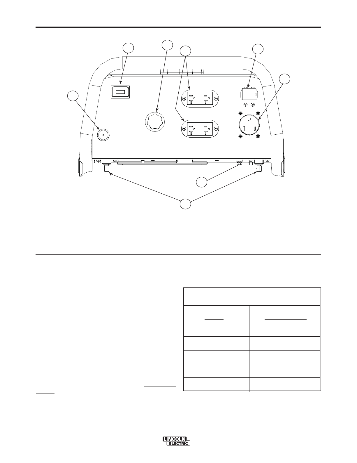
OUTBACK™ 145 OUTPUT CONNECTIONS
A-4
8
1. CURRENT CONTROL DIAL
2. WELD OUTPUT TERMINALS (2)
3. GROUND STUD
4. CIRCUIT BREAKER 20 Amp
7
1
6
3
2
4
5
FIGURE A.1
5. RECEPTACLE - 240 VOLT, 50 AMP
6. DUPLEX RECEPTACLE (2)- 120 VOLT, 20 AMP
7. HOURMETER
8. CHOKE LEVER
ELECTRICAL OUTPUT CONNECTIONS
See Figure A.1 for the location of the current control
dial, weld output terminals, ground stud, circuit breakers, 240 and 120 volt receptacles.
WELDING CABLE CONNECTIONS
Cable Size and Length
Be sure to use welding cables that are large enough.
The correct size and length becomes especially important when you are welding at a distance from the
welder.
Table A.1 lists recommended cable sizes and lengths
for rated current and duty cycle. Length refers to the
distance from the welder to the work and back to the
welder. Cable diameters are increased for long cable
lengths to reduce voltage drops.
OUTBACK™ 145
TABLE A.1
RECOMMENDED WELDING CABLE
SIZE AND LENGTH
TOTAL COMBINED LENGTH OF
ELECTRODE AND WORK CABLES
Cable
Length
0-50 ft (0-15m)
50-100 ft (15-30 m)
100-150 ft (30-46 m)
150-200 ft (46-61 m)
200-250 ft (61-76m)
]
125 Amps
30% Duty Cycle
6 AWG
5 AWG
3 AWG
2 AWG
1 AWG
Page 12

A-5
®
Cable Installation
INSTALLATION
MACHINE GROUNDING
A-5
Install the welding cables to your OUTBACK™ 145 as
follows. See Figure A.1 for the location of parts.
1. The gasoline engine must be OFF to install welding cables.
2. Remove the 1/2-13 flanged nuts from the output
terminals.
3. Connect the electrode holder and work cables to
the weld output terminals. Normally, the electrode
cable is connected to the positive (+) output stud.
4. Tighten the flanged nuts securely.
5. Be certain that the metal piece you are welding
(the “work”) is securely connected to the work
clamp and cable.
6. Check and tighten the connections periodically.
CAUTION
• Loose connections will cause the output studs to
overheat and the studs may eventually melt.
• Do not cross welding cables at output stud connec-
tion. Keep isolated and separate from one another.
------------------------------------------------------------------------
Because this portable engine driven welder or generator creates its own power, it is not necessary to connect its frame to an earth ground, unless the machine
is connected to premises wiring (your home, shop,
etc.).
To prevent dangerous electric shock, other equipment
to which this engine driven welder supplies power,
must:
a) be grounded to the frame of the welder using a
grounded type plug
or
b) be double insulated
When this welder is mounted on a truck or trailer, the
machine grounding stud must be securely connected to the metal frame of the vehicle.
In general if the machine is to be grounded, it should
be connected with a #8 or larger copper wire to a solid
earth ground such as a metal water pipe going into
the ground for at least ten feet and having no insulated joints, or to the metal framework of a building
which has been effectively grounded. The U.S.
National Electrical Code lists a number of alternate
means of grounding electrical equipment. A machine
grounding stud marked with the symbol is provided on the front of the welder.
WARNING
Lincoln Electric offers a welding accessory kit with #6
welding cables. See the ACCESSORIES section of
this manual for more information.
For more information on welding , see WELDING
OPERATION in the OPERATION section of this manual.
DO NOT GROUND MACHINE TO A PIPE WHICH
CARRIES EXPLOSIVE OR COMBUSTIBLE
MATERIAL.
------------------------------------------------------------------------
OUTBACK™ 145
]
Page 13

A-6
®
INSTALLATION
PLUGS AND HAND HELD EQUIPMENT
A-6
PREMISES WIRING
For further protection against electric shock, any electrical equipment connected to the generator receptacles must use a three-blade, grounded type plug or an
Underwriterʼs Laboratories (UL) approved double
insulated tool with a two blade plug.
WARNING
Never operate this machine with damaged or
defective cords. All electrical equipment must be
in safe operating condition.
------------------------------------------------------------------------
AUXILIARY POWER RECEPTACLES
The control panel of the OUTBACK™ 145 features
three auxiliary power receptacles:
• Two 20 amp,120 volt duplex (double outlet)
receptacle.
• A 50 amp, 240 volt single outlet receptacle.
See Figure A.1
Through these receptacles the machine can supply up
to 4750 watts peak or 4250 watts continuous of single-phase 60 Hertz AC power. The machine output
voltages meet UL standards and fall within ± 10% of
the rated voltage.
The OUTBACK™ 145 is not recommended for
premises wiring. The OUTBACK™ 145 does not have
a combined 120/240 volt receptacle and cannot be
connected to a premises.
The OUTBACK™ 145 is intended only for backup
intermittent power.
Certain electrical devices cannot be provided by the
OUTBACK™ 145. Refer to table A.2 for these
devices.
CIRCUIT BREAKERS
Auxiliary power is protected by circuit breakers. When
the machine is operated in high temperature environments, the breakers may tend to trip at lower loads
than normally.
CAUTION
NEVER BYPASS THE CIRCUIT BREAKERS. WITH-
OUT OVERLOAD PROTECTION, THE UNIT COULD
OVERHEAT AND/OR CAUSE DAMAGE TO THE
EQUIPMENT BEING USED.
------------------------------------------------------------------------
OUTBACK™ 145
]
Page 14

A-7
®
INSTALLATION
CAUTION
Certain Electrical devices cannot be powered to this Product. See Table A.2
TABLE A.2
ELECTRICAL DEVICE USE WITH THIS PRODUCT
A-7
Type
Resistive
Capacitive
Inductive
Common Electrical Devices
Heaters, toasters, incandescent
light bulbs, electric range, hot
pan, skillet, coffee maker.
TV sets, radios, microwaves,
appliances with electrical control.
Single-phase induction motors,
drills, well pumps, grinders, small
refrigerators, weed and hedge
trimmers.
Possible Concerns
NONE
Voltage spikes or high voltage
regulation can cause the capacitative elements to fail. Surge
protection, transient protection, and
additional loading is recommended for 100% fail-safe operation. DO NOT RUN
THESE DEVICES WITHOUT
ADDITIONAL RESISTIVE TYPE
LOADS.
These devices require large
current inrush for starting. (See
Table B.3, GENERATOR POWER
APPLICATIONS, in the OPERATION section of this manual for
required starting wattages.)
Some synchronous motors may
be frequency sensitive to attain
maximum output torque, but
they SHOULD BE SAFE from
any frequency induced failures.
Capacitive / Inductive
The Lincoln Electric Company is not responsible for any damage to electrical components
improperly connected to this product.
Computers, high resolution TV sets,
complicated electrical equipment.
OUTBACK™ 145
]
An inductive type line conditioner along with transient and
surge protection is required,
and liabilities still exist.
DO NOT USE THESE DEVICES
WITH THIS PRODUCT.
Page 15

B-1
®
SAFETY INSTRUCTIONS
OPERATION
B-1
WARNING
ELECTRIC SHOCK
can kill.
• Do not touch electrically live parts
or electrode with skin or wet
clothing.
• Insulate yourself from work and
ground.
• Always wear dry insulating
gloves.
FUMES AND GASES
can be dangerous.
• Keep your head out of fumes.
• Use ventilation or exhaust to
remove fumes from breathing
zone.
WARNING
ENGINE EXHAUST can kill.
• Use in open, well ventilated areas
or vent exhaust outside.
• Do not stack anything on or near
the engine.
MOVING PARTS can injure.
• Do not operate with doors open or
guards off.
• Stop engine before servicing.
• Keep away from moving parts.
Only qualified personnel should install, use, or
service this equipment.
Observe additional Safety Guidelines detailed
throughout this manual.
WELDING SPARKS
can cause fire or
explosion
• Keep flammable material away.
• Do not weld on containers that
have held combustibles.
ARC RAYS
can burn.
• Wear eye, ear and body
protection.
OUTBACK™ 145
]
Page 16

B-2
®
OPERATION
GRAPHIC SYMBOLS USED ON THIS EQUIPMENT OR IN THIS MANUAL
B-2
WARNING /
CAUTION
OIL
FUEL
WORK CLAMP
CHOKE
AIR CLEANER
CIRCUIT
BREAKER
GROUND
(AUXILIARY
POWER)
ELECTRODE
WELDING ARC
OUTBACK™ 145
]
Page 17

B-3
®
OPERATION
GENERAL DESCRIPTION
The OUTBACK™ 145 is designed for commercial use
welder/generator applications. As a welder it provides
145 amps of DC constant current for welding with DC
stick electrodes. A single dial lets you select a full
range of welding output from 50 to 145 amps.
As a generator it can supply up to surge watts or
continuous watts of 120 / 240 volt, single-phase AC
power. The machine is portable.
A Kohler CH395 9.5 HP air cooled, OHV gasoline
engine powers the welder / generator. It has an
engine warranty of 3 years.
RECOMMENDED APPLICATIONS
Welder
The OUTBACK™ 145 provides excellent constant
current DC welding output for stick (SMAW) welding.
B-3
DESIGN FEATURES AND
ADVANTAGES
• 145 amp DC constant current welding for stick
electrodes.
• Lightweight / portable.
• Full range, continuous welding output control with
a single knob.
• Hour Meter Standard.
• Surge watts or Watts of continuous 120 / 240 volt
single phase AC auxiliary power.
• Kohler CH395 overhead valve air-cooled gasoline
engine. Smooth running, long life.
WELDING CAPABILITY
The OUTBACK™ 145 is rated at 100 amps, 25VDC at
60% duty cycle on a ten-minute basis. This means
that you can load the welder to 100 amps for six-minutes out of every ten-minute period. The machine is
capable of higher duty cycles at lower output currents.
Generator
The OUTBACK™ 145 gives smooth AC generator
output for continuous auxiliary power usage within the
engine manufacturerʼs required maintenance recommendations.
OPERATIONAL FEATURES AND
CONTROLS
The OUTBACK™ 145 was designed for simplicity.
Therefore, it has very few operating controls. A single
dial on the control panel lets you select either welder
or generator use. For welding, the same dial selects
continuous current output over the machineʼs 50 to
145 amp range.
The gasoline engine controls include a recoil starter,
choke and stop switch. See ENGINE OPERATION in
the OPERATION section of this manual for details
about starting, running, stopping, and breaking in the
gasoline engine.
The current is continuously variable from 50 to 145
amps DC. The OUTBACK™ 145 can, therefore, weld
with 3/32”, 1/8” and some 5/32” diameter Lincoln DC
electrodes.
LIMITATIONS
• The OUTBACK™ 145 is not recommended for any
processes besides those that are normally performed using stick welding (SMAW) procedures.
• The OUTBACK™ 145 is not recommended for
pipe thawing.
• During welding, generator power is limited to 100
watts, and output voltages can drop from 120 to 80
volts and 240 to 160 volts. Therefore, DO NOT
OPERATE ANY SENSITIVE ELECTRICAL
EQUIPMENT WHILE YOU ARE WELDING.
OUTBACK™ 145
]
Page 18

B-4
®
CONTROLS AND SETTINGS
OPERATION
All welder/generator controls are located on the Output Control Panel.
B-4
Gasoline engine controls are mounted on the engine. See Figure B.1 and the figures in engine operation section.
OUTPUT PANEL CONTROLS
8
9
1
FIGURE B.1
7
5
2
6
WELDER/GENERATOR CONTROLS
See Figure B.1 for the location of the following features:
1. CURRENT CONTROL DIAL: Adjusts continuous cur-
rent output. The amperages on the dial correspond to
the approximate amperages needed for specific
Lincoln welding electrodes.
2. 20 AMP CIRCUIT BREAKER: Provides overload cur-
rent protection for the 120 Volt and 240 Volt
Receptacles
3. WELD POSITIVE
connection point for either the electrode holder or the
work cable. (Because the OUTBACK™ 145 is a DC
output machine, either output terminal can be used for
either cable.)
4. WELD NEGATIVE
connection point for either the electrode holder or the
work cable. (Because the OUTBACK™145 is a DC
output machine, either output terminal can be used for
either cable.)
5. GROUND STUD: Provides a connection point for con-
necting the machine case to earth ground for the
safest grounding procedure.
6. 240 VOLT RECEPTACLE: Connection point for sup-
plying 250 volt power to operate one electrical device.
7. 120 VOLT DUPLEX RECEPTACLES (2): Connection
point for supplying 120 volt power to operate one or
has run for maintenance purposes.
OUTPUT TERMINAL: Pro vides the
OUTPUT TERMINAL: Provides the
3 or 4
8. HOUR METER: Records the time that the engine has
run for maintenance purposes.
9. CHOKE LEVER: (See Engine Operation Section)
ENGINE OPERATION
Starting/Shutdown Instructions
Be sure all Pre-Operation Engine Service has been
performed. Also, Read owners manual before starting
for the first time. (See INSTALLATION section)
NOTE: Remove all loads connected to the AC power
receptacles before starting the gasoline
engine. Put the “ON/OFF” Switch in the
“ON”(I) position.
FOR A “COLD” ENGINE:
Open the fuel shutoff valve.
Place the choke lever in the “CHOKE” position.
Pull slightly on the recoil starter handle until resistance
is felt.
Pull the cord rapidly.
If the engine does not start, open the choke slightly
and pull the starter cord rapidly again.
OUTBACK™ 145
]
Page 19

B-5
®
When the engine starts, gradually open the choke to
the “RUN” position. To open the choke fully requires
an engine warm-up period of several seconds to several minutes, depending on the temperature. After
starting the engine, first open the choke (toward RUN)
until the engine just begins to run smoothly. Then
open the choke in small steps, allowing the engine to
accept small changes in speed and load, until the
choke is fully open (in RUN). During engine warm-up
the equipment can be operated.
FOR A “HOT” ENGINE:
Open the fuel shutoff valve.
Place the choke lever in the “RUN” position.
Closing the choke of a hot engine will flood
the carburetor and prevent starting.
OPERATION
B-5
FIGURE B.2
Pull slightly on the recoil starter handle until resistance
is felt.
Pull the cord rapidly.
FOR BEST ENGINE STARTING:
• Always use fresh gasoline and be sure the filter is
clean and properly maintained.
• If you use an alternate fuel tank or supply, be sure to
install an in-line fuel filter.
• Do not pull the recoil starter with the choke in
the “CHOKE” position more than one time.
Repeated pulls on a choked engine will flood
the carburetor.
• If the engine will not start, see the TROU-
BLESHOOTING section of this or the engine
ownerʼs manual
Stopping the Engine
Remove all welding and auxiliary power loads and
allow engine to run for a few minutes to cool the
engine.
Stop the engine by placing the “ON/OFF” switch in
the “OFF”(O) position.
Break-in Period
It is normal for any engine to use larger quantities of
oil until break-in is accomplished. Check the oil level
twice a day during the break-in period (about 50 running hours). Change the oil after the first 5 hours of
operation. See the Engine Instruction Manual for further details.
CAUTION
IN ORDER TO ACCOMPLISH THIS BREAK-IN, THE
UNIT SHOULD BE SUBJECTED TO MODERATE
LOADS, WITHIN THE RATING OF THE MACHINE.
AVOID LONG IDLE RUNNING PERIODS. REMOVE
LOADS AND ALLOW ENGINE TO COOL SEVERAL
MINUTES AT LOW IDLE BEFORE SHUTDOWN.
------------------------------------------------------------------------
Low Oil Sensing
This engine has a built in sensor which responds to
low oil level (not pressure). When activated, the system will shut the engine down. The engine will not
restart until sufficient oil is added. Check oil level frequently and add oil as required to the full mark on the
dipstick. DO NOT OVERFILL.
Typical Fuel Consumption
WARNING
Close the fuel valve when the machine is
transported to prevent fuel leakage from
the carburetor.
------------------------------------------------------------------------
Fuel Valve is located under the fuel tank and above
the recoil starter see figure B.2 for “ON/OFF” positions.
KOHLER CH395
NO LOAD .30 GALLONS/HOUR
3750 R.P.M. 1.14 ( LITERS/HOUR)
DC CC WELD OUTPUT .51GALLONS/HOUR
80 AMPS, 25 VOLTS 1.93 ( LITERS/HOUR)
AUXILIARY POWER .82 GALLONS/HOUR
4000 KVA 3.10 ( LITERS/HOUR)
OUTBACK™ 145
]
Page 20

B-6
®
OPERATION
WELDING OPERATION
WARNING
ELECTRIC SHOCK can kill.
• Do not touch electrically live parts
or electrode with skin or wet clothing.
• Insulate yourself from work and
ground.
• Always wear dry insulating gloves.
ENGINE EXHAUST can kill.
• Use in open, well ventilated areas
or vent exhaust outside.
• Do not stack anything on or near
the engine.
MOVING PARTS can injure.
• Do not operate with doors open or
guards off.
• Stop engine before servicing.
• Keep away from moving parts.
Only qualified personnel should install, use, or
service this equipment.
B-6
4. Insert the electrode into the electrode hold
5. Set the current control dial to the desired output
current .
6. Start the gasoline engine.
See ENGINE OPERATION in this section of
the manual.
7. Strike an arc and begin welding.
AFTER YOU FINISH THE WELD:
1. Stop the gasoline engine. See ENGINE OPERA-
TION in this section of the manual.
2. Allow the electrode and work to cool completely.
3. Remove the work clamp from the work.
4. Remove any remaining piece of electrode from the
electrode holder.
5. If you are finished using the OUTBACK 145 for weld-
ing, disconnect the welding cables from the weld output terminals. Reattach the flange nuts and leave
them on the terminals.
For DC+ welding, the electrode cable is to be connected
to the “+” output stud and work cable to the “-” output
stud. (For DC- welding, reverse these connections.)
Semi-automatic Wire Welding with a Lincoln Wire
Feeder/Welder
er.
The OUTBACK™ 145 can deliver from 50 to 145
amps of welding output current . Output can be
adjusted by setting the current control dial on the output control panel.
You can get maximum welding output by setting the
dial to 145 AMPS. At high current settings like this,
some output may decrease as the machine is used. If
you are welding for a long time, you may need to turn
the dial slightly upward to maintain the same results.
The numbers on the dial correspond to the approximate amps needed to weld using specific Lincoln
welding rods. Table B.2, WELDING APPLICATIONS,
give you the recommended dial settings based on the
thickness of the work and the size and type of rod
youʼre using.
TO USE THE
1. Remove the flange nuts from the weld output terminals and place the work and electrode welding
cables over the terminals. See Figure B.1 and
B.1a. Replace and tighten the flange nuts
securely. Be sure the connections are tight.
2. Select the appropriate electrode. See Table B.2
3. Attach the work clamp securely to the work you are
welding.
OUTBACK™ 145
FOR WELDING:
OUTBACK™ 145
The
supply up to 4250 watts continuous input power to a
Lincoln Wire Feeder/Welder. The Wire Feeder/ Welder is
equipped with all the supplies needed for Flux-Cored Arc
Welding (FCAW). Also some Wire Feeder/Welders come
equipped with the essentials needed for Gas Metal Arc
Welding (GMAW) or MIG processes, while others require
the purchase of a conversion kit. These products are
available where Lincoln products are sold. Contact your
local authorized Lincoln representative for more details.
Plasma Cutting with Lincoln Pro-Cut 25.
The
OUTBACK™ 145
supply up to 4250 watts continuous input power to a ProCut 25. The Pro-Cut will work satisfactorily under the following conditions:
1. Set the Current Control on the
the 145 amp position. (Higher Settings may result in a
shutdown of the Pro-Cut 25.)
2. Leave the "ON/OFF" switch on the Pro-Cut "OFF"
until the
at full operating speed.
OUTBACK™ 145
generator power can be used to
generator power can be used to
OUTBACK™ 145
has been started and is
to
OUTBACK™ 145
]
Page 21

B-7
®
OPERATION
B-7
120V Receptacle Operation:
• Set the Output Control on the Pro-Cut 25 no higher
than the 15 amp position.( Higher settings may cause
circuit breaker on the
• Maximum material thickness that can be cut is 1/4".
240V Receptacle Operation:
• The Pro-Cut 25 may be used for its full range of control.
• Maximum material thickness that can be cut is 3/8".
OUTBACK™ 145
to trip.)
AUXILIARY POWER OPERATION
WARNING
Be sure that any electrical equipment plugged into
the generator AC power receptacles can withstand
a ±10% voltage and a ±5% frequency variation.
Some electronic devices cannot be powered by
the OUTBACK™ 145 Refer to Table A.2, ELECTRICAL DEVICE USE WITH THE OUTBACK™ 145, in
the INSTALLATION section of this manual.
-------------------------------------------------------------
GENERAL INFORMATION
The OUTBACK™ 145 is rated at 4750 Peak watts or
4250 continuous watts. It provides both 120 volt and
240 volt power. You can draw up to 20 amps from
either side of the 120 volt duplex receptacle, but not
more than 35.4 amps from both sides at once. Up to
17.7 amps can be drawn from the single 240 volt
receptacle.
Electrical loads in watts are calculated by multiplying
the voltage rating of the load by the number of amps it
draws. (This information is given on the load device
nameplate.) For example, a device rated 120 volts, 2
amps will need 240 watts of power (120 x 2 = 240).
You can use Table B.3, AUXILIARY POWER APPLICATIONS, to determine the wattage requirements of
the most common types of loads you can power with
the OUTBACK™ 145 Be sure to read the notes at the
bottom of the table.
TO USE THE OUTBACK 145 AS AN AUXILIARY
POWER SUPPLY:
1. Start the gasoline engine. See ENGINE OPERATION in this section of the manual.
2. Set the current control dial on the output control
panel to “MAX.” See Figure B.1.
3. Plug the load(s) into the appropriate 120 volt or
240 volt power receptacle.
NOTE: During welding, the maximum generator out-
put for auxiliary loads is 100 watts.
NOTE: You can supply multiple loads as long as the
total load does not exceed 4750 Peak watts
or 4750 continuous watts. Be sure to start the
largest loads first.
TABLE B.2
ELECTRODE SELECTION GUIDE
CURRENT RANGE (AMPS)
AWS ELECTRODE
CLASSIFICATION ELECTRODE TYPE POLARITY
3/32 SIZE 1/8 SIZE 5/32 SIZE
E6010 FLEETWELD® 5P DC+ 50-75 75-135 E6011 FLEETWELD® 35 DC+ 50-75 70-110 80-125
E6011 FLEETWELD® 180 DC+ 50-80 55-110 105-125
E6013 FLEETWELD® 37 DC± 70-95 100-135 E7018 EXCALIBUR® 7018 DC+ 70-100 90-125 125-145
E7018 JETWELD® LH-73 DC+ 65-85 90-125 -
E708-17 & E308L-17
ENi-CI SOFTWELD® 99Ni DC+ 50-80 80-110 -
- WEARSHIELD® ABR DC+ - 50-150 -
BLUE MAX® 308/308L AC-DC
SHEET THICKNESS THINNER 1/8 AND THICKER
DC+ 50-80 75-110 80-125
1/8 AND
OUTBACK™ 145
]
Page 22

B-8
®
OPERATION
TABLE B.3
AUXILIARY POWER APPLICATIONS
Suggested Power Applications Running Watts *Start-up Watts
(Continuous) (Peak)
*Air Compressor - 1 HP 2,000 4,000 - 8,000
*Air Compressor - 3/4 HP 1,250 3,100 - 5,000
*Airless Sprayer - 1/3 HP 600 1,500 - 2,400
Chain Saw 1,200
Circular Saw 1,200
Coffee Maker 1,000
*Deep Freezer 500 750 - 2,000
*Electric Motor - 1 HP 1,000 2,500 - 4,000
Electric Range (1 element) 1,500
Electric Skillet 1,250
*Furnace Fan - 1/3 HP 1,200 3,000 - 4,800
Portable Grinder (4 1/2”) 600
Portable Grinder (7”) 2,000
Halogen Work Light 500
Hand Drill - 1/4” 500
Hand Drill - 3/8” 700
1500 Watt Heater 1,500
Hedge Trimmer 450
Light Bulb 100
Reciprocating Saw 900
Radial Arm Saw 2,600
Radio 50
*Refrigerator/Freezer (small) 600 1,500 - 2,400
Slow Cooker 200
*Submersible Pump - 1 HP 1,000 2,500 - 4,000
*Sump Pump 600 1,500 - 2,400
Toaster 1,100
Weed Trimmer 500
Lincoln Wire Feeder/Welder 4,000
B-8
NOTES:
Wattages listed are approximate. Check your equipment for actual wattage.
Equipment with unusually high *START-UP WATTS are listed. For start-up of other equipment that uses
a motor, listed in the table, multiply RUNNING WATTS by 2.
Multiple loads can be used as long as the total load does not exceed 4750 Peak watts. Be sure to start
the largest loads first.
OUTBACK™ 145
]
Page 23

C-1
®
ACCESSORIES
OPTIONS/ACCESSORIES
The following options/accessories are available for
your OUTBACK™145 from your local Lincoln
Distributor:
ACCESSORY KIT (K875) – Includes the following:
• Twenty feet (6.1 meters) of #6 AWG electrode cable
with lug.
• Fifteen feet (4.6 meters) of #6 work cable with lugs.
• Work Clamp
• Headshield with No. 10 filter
• Insulated electrode holder and sample electrodes
150 amp capacity.
UNDERCARRIAGE (K2722-1) - A two-wheeled, hand
movable undercarriage is available for field installation.
ROTOR REMOVAL KIT (S20925) - A service kit with
thru bolt and impact bolts for removing the generator
rotor from tapered engine crank shaft.
C-1
CANVAS COVER (K2804-1) - To protect the
Outback® 145 when not in use. Made from attractive
red canvas material that is flame retardant, mildew
resistant and water repellent.
LIFT BAIL KIT (K2819-1)
Easily installed kit for lifting the machine with a fixed
lifting point.
OUTBACK™ 145
]
Page 24

D-1
®
MAINTENANCE
SAFETY PRECAUTIONS
WARNING
• Have qualified personnel do all maintenance and
troubleshooting work.
• Turn the engine off before working inside the
machine.
• Remove guards only when necessary to perform
maintenance and replace them when the maintenance requiring their removal is complete.
• If guards are missing from the machine, get replacements from a Lincoln Distributor. See the EXPLODED VIEW AND PARTS LIST at the back of this
manual.
-----------------------------------------------------------------------
D-1
OIL: Check the oil level after every 5
hours of operation or daily. BE SURE
TO MAINTAIN THE OIL LEVEL.
Change the oil the first time after 20 hours of operation. Then, under normal operating conditions,
change the oil after every 100 hours or once a year,
whichever occurs first. If the engine is operated
under heavy load or in high ambient temperatures,
change the oil every 50 hours.
Drain the oil from the drain plug located on either side
of the engine bottom, as shown in Figure D.1. Refill
through the oil fill plug until the oil reaches the full
mark on the dip stick. See Engine Ownerʼs manual
for specific oil recommendations.
FIGURE D.1 - OIL DRAIN AND
REFILL LOCATION
Read the Safety Precautions in the front of this manual and in the Kohler CH395 Operating and
Maintenance Instructions manual before working on
the OUTBACK™145 Keep all equipment safety
guards, covers, and devices in position and in good
repair. Keep your hands, hair, clothing, and tools
away from the recoil housing, fans, and all other moving parts when starting, operating, or repairing this
machine.
ROUTINE AND PERIODIC
MAINTENANCE
ENGINE MAINTENANCE
CAUTION
To prevent the engine from accidentally starting, disconnect the spark plug lead before servicing the
engine.
-----------------------------------------------------------------------
See the Kohler CH395 Ownerʼs manual for a summary of maintenance intervals for the engine. Follow
either the hourly or the calendar intervals, whichever
come first. More frequent service may be required,
depending on your specific application and operating conditions. The Kohler CH395
shows engine maintenance replacement parts and
numbers.
Ownerʼs manual
OIL
Do not screw in
dipstick to check oil
FILL to FULL mark on
dipstick - recheck
12 mm
OIL
Tighten dipstick
firmly before starting
FUEL: At the end of each dayʼs use, refill
the fuel tank to minimize moisture condensation and dirt contamination in the
fuel line.
AIR CLEANER: With normal operating
conditions, the maintenance schedule for
cleaning and re-oiling the foam pre-filter
is every 50 hours and replacement of the
air cleaner filter element every 100 hours.
More frequent servicing is required with dusty operating conditions. Refer to the maintenance section of
the Engine Ownerʼs Manual for more information.
HEX
Drain
plug
Oil drain
OIL DRAIN
PLUG
OUTBACK™ 145
]
Page 25

D-2
®
MAINTENANCE
To service the pre-cleaner:
Remove the cover. Carefully remove the foam precleaner from the filter element.
1. Wash in liquid detergent and water.
2. Squeeze dry in a clean cloth.
3. Saturate in clean engine oil.
4. Squeeze in a clean, absorbent cloth to remove all
excess oil.
Carefully place the pre-cleaner back over the filter element and reinstall the air cleaner cover and wing nuts.
CLEAN ENGINE: Remove dirt and debris with a cloth
or a brush. Do not clean with a forceful spray of
water. Water might contaminate the fuel system. Use
low pressure air to blow out the machine periodically.
In particularly dirty locations this may be required
once a week.
D-2
ENGINE ADJUSTMENTS
WARNING
OVERSPEED IS HAZARDOUS - The maximum
allowable high idle speed for this machine is 3750
RPM, no load. Do NOT tamper with the governor
components or setting or make any other
adjustments to increase the maximum speed.
Severe personal injury and damage to the
machine can result if operated at speeds above
maximum.
------------------------------------------------------------------------
Adjustments to the engine are to be made only by a
Lincoln Service Center or an authorize Field Service
Shop.
SLIP RINGS
CAUTION
SPARK PLUG SERVICE
The Spark plug can be serviced by either of the following methods: See Figure D.2.
FIGURE D.2
METHOD 2
METHOD 1
Spark Plug
Location
Roof and Panel
Removed
Spark Plug
Location
1. Access Spark Plug by reaching underneath the side
panel near the muffler.
2. Remove 20 screws securing the roof, and side
panel to gain access to the Spark Plug. Be sure to
support the fuel tank tray and control panel once
the side panel is removed.
CAUTION
• Be sure not to cross thread Spark Plug when
reinstalling.
• This area is HOT if engine has been running.
Allow engine to cool before servicing.
------------------------------------------------------------------------
A slight amount of darkening and wear of the slip
rings and brushes is normal. Brushes should be
inspected when a general overhaul is necessary.
If brushes are to be replace, clean slip rings with a
fine emery paper.
Do not attempt to polish slip rings while engine is
running.
------------------------------------------------------------------------
HARDWARE
Both English and Metric fasteners are used in this
welder.
ENGINE MAINTENANCE PARTS
KOHLER CH395
Air Filter Element Kolher 17 083 18-S
Spark Plug Champion RC 12YC
(Resistor Type) (Gap .030” [.76mm])
OPERATIONAL CLEARANCE
CAUTION
Approximately 12-18” of clearance should be
around this unit during operation for air flow.
Reducing this clearance will reduce air flow to the
machine causing operational temperatures to
increase. Possible damage to the machine can
result if to much air flow is restricted.
------------------------------------------------------------------------
OUTBACK™ 145
]
Page 26

®
E-1
TROUBLESHOOTING
HOW TO USE TROUBLESHOOTING GUIDE
WARNING
Service and Repair should only be performed by Lincoln Electric Factory Trained Personnel.
Unauthorized repairs performed on this equipment may result in danger to the technician and
machine operator and will invalidate your factory warranty. For your safety and to avoid Electrical
Shock, please observe all safety notes and precautions detailed throughout this manual.
__________________________________________________________________________
E-1
This Troubleshooting Guide is provided to help you
locate and repair possible machine malfunctions.
Simply follow the three-step procedure listed below.
Step 1. LOCATE PROBLEM (SYMPTOM).
Look under the column labeled “PROBLEM (SYMPTOMS)”. This column describes possible symptoms
that the machine may exhibit. Find the listing that
best describes the symptom that the machine is
exhibiting.
Step 2. POSSIBLE CAUSE.
The second column labeled “POSSIBLE CAUSE” lists
the obvious external possibilities that may contribute
to the machine symptom.
Step 3. RECOMMENDED COURSE OF ACTION
This column provides a course of action for the
Possible Cause, generally it states to contact your
local Lincoln Authorized Field Service Facility.
If you do not understand or are unable to perform the
Recommended Course of Action safely, contact your
local Lincoln Authorized Field Service Facility.
CAUTION
If for any reason you do not understand the test procedures or are unable to perform the tests/repairs safely, contact your
Local Lincoln Authorized Field Service Facility for technical troubleshooting assistance before you proceed.
OUTBACK™ 145
]
Page 27

E-2
®
Observe all Safety Guidelines detailed throughout this manual
PROBLEMS
(SYMPTOMS)
TROUBLESHOOTING
POSSIBLE
CAUSE
OUTPUT PROBLEMS
E-2
RECOMMENDED
COURSE OF ACTION
Major Physical or Electrical
Damage is Evident.
No Generator power or welding
output
Generator power is available
but unit will not weld.
1. Contact your local Lincoln
Authorized Field Service Facility.
1. Check brushes for wear. See
Maintenance section.
2. Check for loose or faulty
connections at brush holders.
3. Open lead in flashing or field
circuit.
4. Rheostat (R1) lead broke.
5. Dirty slip rings.
6. Faulty rheostat (R1).
7. Faulty field bridge rectifier (D1).
8. Faulty field capacitor (C1).
9. Faulty stator field winding.
10. Faulty rotor.
1. Loose connector to output stud.
2. Work not connected.
3. Electrode holder loose.
4. No open circuit voltage at output
studs. Open lead in weld circuit.
5. Faulty output bridge rectifier.
6. Faulty choke (L1).
If all recommended possible areas
of misadjustment have been
checked and the problem persists,
Contact your local Lincoln
Authorized Field Service Facility.
Unit will weld but low or no
generator power is available.
No auxillary power but machine has
weld output.
1. Circuit breaker is open.
2. Loose or open connection with
electrical plug-in component.
3. Current control dial not at “MAX”
4. No open circuit voltage at
receptacle.
1. Check CB1 and CB2 - Reset if
tripped.
CAUTION
If for any reason you do not understand the test procedures or are unable to perform the tests/repairs safely, contact your
Local Lincoln Authorized Field Service Facility for technical troubleshooting assistance before you proceed.
OUTBACK™ 145
]
Page 28

E-3
®
TROUBLESHOOTING
Observe all Safety Guidelines detailed throughout this manual
E-3
PROBLEMS
(SYMPTOMS)
Recoil starter is hard to pull.
Engine will not start or starts but
runs rough with low power.
Engine runs erratically or stops running.
POSSIBLE
CAUSE
ENGINE PROBLEMS
1. Crankcase may be over-filled
with oil. - Check oil level.
1. Water in engine from rain and /
or condensation. - Remove spark
plug and dry it if wet. Blow low
pressure compressed air in
spark plug port while pulling
recoil starter. Re-install spark
plug.
2. Spark plug may be faulty.
3. Air filter element saturated with
water and / or oil - Replace.
1. Engine is not fully warmed-up
and engine choke is in the fullyopen (RUN) position.
2. Engine requires service to head,
carburetor, filters, oil spark plug
and / or gas.
3. Oil level to low.
RECOMMENDED
COURSE OF ACTION
If all recommended possible areas
of misadjustment have been
checked and the problem persists,
Contact your local Lincoln
Authorized Field Service Facility.
Engine sputters but will not start.
Arc is erratic and “pops out”.
1. Bad gas, bad filter, air cleaner,
spark plug, and / or breather.
1. Check Work and Electrode
cables for loose or faulty connection.
2. Electrode may be wet.
CAUTION
If for any reason you do not understand the test procedures or are unable to perform the tests/repairs safely, contact your
Local Lincoln Authorized Field Service Facility for technical troubleshooting assistance before you proceed.
OUTBACK™ 145
]
Page 29

F-1
®
ENHANCED DIAGRAM
DIAGRAMS
F-1
A
240 VAC
J6
L15917
GND-F
J4
120 VAC
SILVER
3B
GND-D
5A
3A
GND
CB1
20A
GROUND STUD ON
CONTROL PANEL FRONT
3
201B
5 5A
5
9
7
SLIP
RINGS
ROTOR
FIELD
+
-
202A
201A
3
J5
120 VAC
6A
SILVER
5B
GND-E
+
ELECTRODE
6B
ELEC
L1
CHOKE
_
WORK
6A
EC-A
CB1
5B
NEUTRAL STUD
20A
ON CONTROL
PANEL FRONT
6
W2
WORK
+
203
SUPPRESSOR
ASSEMBLY
D1
_
204
W1
ENGINE
C1
201D
600 μFD
202 202C
(-)
WIRING DIAGRAM - OUTBACK 145
(+)
D3
201C
202B
201
Ω
100 W
3.3
OUTPUT
RHEOSTAT
200A
200
(+)
(-)
HOUR
METER
200C
205
FRAME
(+)
9
(-)
D2
201B
7
GROUND
SUPPORT
GENERATOR
GND
GND-H
ENGINE WIRI NG
205
FOOT
RUN/STOP
SWITCH
SHOWN IN
STOP
POSITION
MODULE
B
SWITCH
LOW OIL
Y
Y
MAG
OUTBACK™ 145
]
NOTE: This diagram is for reference only. It may not be accurate for all machines covered by this manual. The specific diagram for a particular code is pasted inside the
machine on one of the enclosure panels. If the diagram is illegible, write to the Service Department for a replacement. Give the equipment code number.
Page 30

F-2
®
DIMENSION PRINT
F-2
12.25
A.02
M22562
15.75
N.A.
31.48
7.30
25.62
14.17
21.77
BOTTOM VIEW
.41 HOLE
(4 PLACES)
17.50
NOTES:
N.A. CENTER OF GRAVITY WITH OIL IN ENGINE
AND EMPTY FUEL TANK.
OUTBACK™ 145
]
Page 31

PARTS LIST FOR
OUTBACK
P-671P-671
®
145
This parts list is provided as an informative guide only.
It was accurate at the time of printing. These pages are only updated on the
Service Navigator DVD and in Lincoln Electricʼs official Parts Book (BK-34).
When ordering parts, always refer to Lincoln Electricʼs official Parts Book
(BK-34) for the latest pages.
OUTBACK®145
Page 32

ILLUSTRATION OF SUB ASSEMBLIES
1
4
2
3
P-671-AP-671-A
OUTBACK
®
145
11-08-2010
Page 33

P-671-A.1P-671-A.1
Outback®145
For Code: 11732
Do Not use this Parts List for a machine if its code number is not listed. Contact the Service Department for any
code numbers not listed.
Use the Main Assembly drawing on the left hand page and the table below to determine which sub assembly
page and column the desired part is located on for your particular code machine.
Sub Assembly Item
No.
SUB ASSEMBL Y
PAGE NAME
Optional Equipment
PAGE NO.
CODE NO.
11732 1 1 1 1
P-671-B.1
1
Cradle Tube Asbly & Roof
P-671-C
2
Control Panel Assembly
P-671-D
3
Stator & Rotor Assembly
P-671-E
4
Rear Control Panel, Fuel Tank
Assembly & Engine
P-671-F
OUTBACK
®
145
05-22-2012
Page 34

OPTIONAL EQUIPMENT LISTING
P-671-B.1P-671-B.1
Miscellaneous Options Available for your machine are listed below:
# Indicates a change this printing.
DESCRIPTION . . . . . . . . . . . . . . . . . . . . . . . . . . . . . . . . . . . . . . . . . . . . . . . . . . . . . . . . . . . . . . . . . . . . . . .PART NUMBER
Accessory Kit . . . . . . . . . . . . . . . . . . . . . . . . . . . . . . . . . . . . . . . . . . . . . . . . . . . . . . . .Order K875
Undercarriage (Includes S27983 Mounting Kit) (See P-606) . . . . . . . . . . . . . . . . . . .Order K2722-1
Mounting Kit (Hardware Kit for K2722-1 Undercarriage) . . . . . . . . . . . . . . . . . . . . .Order S27983
Rotor Removal Kit . . . . . . . . . . . . . . . . . . . . . . . . . . . . . . . . . . . . . . . . . . . . . . . . . . . .Order S20925
Canvas Cover . . . . . . . . . . . . . . . . . . . . . . . . . . . . . . . . . . . . . . . . . . . . . . . . . . . . . . .Order K2804-1
Lift Bail Kit . . . . . . . . . . . . . . . . . . . . . . . . . . . . . . . . . . . . . . . . . . . . . . . . . . . . . . . . . .Order K2819-1
OUTBACK
®
145
11-08-2010
Page 35

NOTES
OUTBACK®145
Page 36

Cradle Tube Assembly & Roof
10A
4B
15
16
27
17
23
21
19
6B
6A
10B
1
2B
2A
26
2C
6A
24
6B
23
17
24
27
6B
6A
P-671-CP-671-C
10A
10B
19
21
15
16
2A
26
2B
2C
OUTBACK
®
145
4A4A4B
6A
6B
01-25-2011
Page 37

P-671-C.1
P-671-C.1
# Indicates a change this printing.
Use only the parts marked “x” in the column under the
heading number called for in the model index page.
ITEM DESCRIPTION PART NO. QTY. 1 2 3 4 5 6 7 8 9
Cradle Assembly (L13169-5), Includes: NSS 1 X
1 Cradle Tube Welded Assembly L13140-1 1 X
2A Vibration Mount S20984-2 2 X
2B Lock Washer E106A-14 2 X
2C 5/16-18 HN CF000029 2 X
4A Rubber Mount T11991 2 X
4B Self Tapping Screw S9225-64 4 X
6A Side Plate G5956-4 2 X
6B Self Tapping Screw S9225-68 8 X
10A Roof Assembly G6611-1 1 X
10B Self Tapping Screw S9225-68 20 X
15 Logo Decal S27368-3 2 X
16 Family Name Decal S27554 2 X
17 Carbon Monoxide Warning Decal M21436 1 X
19 Fuel Warning Decal T13086-108 1 X
21 Warning Decal M16197 1 X
23 Wiring Diagram L15917 1 X
24 Engine Ignition Decal S28630 1 X
26 Self Tapping Screw S8025-119 2 X
27 Serial Number Decal NSS 1 X
NSS - Not Sold Separately
OUTBACK
®
145
08-01-2012
Page 38

Control Panel Assembly
10A
14
13
11A
9A
1
5
6A
7A
8A
6B
7B
2B
3
12A
30A
32A
4A
2A
15
20
4B
11C
11B
11D
13
P-671-DP-671-D
10A
9A
11A
14
4A
11B
11D
4B
2A
8A
12A
15
20
32A
30A
7A
7B
6A
6B
11C
2B
OUTBACK
®
145
01-25-2011
Page 39

P-671-D.1
P-671-D.1
# Indicates a change this printing.
Use only the parts marked “x” in the column under the
heading number called for in the model index page.
ITEM DESCRIPTION PART NO. QTY. 1 2 3 4 5 6 7 8 9
Control Panel Assembly (G5959-5), Includes: NSS 1 X
1 Control Panel G5935-2 1 X
2A Receptacle S18907-4 1 X
2B Sems Screw T10082-30 4 X
3 Receptacle Cover M21760 1 X
4A Circuit Breaker M20585-2 1 X
4B Circuit Breaker Cover Seal S24911-2 1 X
4C Sems Screw (Not Shown) T10082-30 4 X
4D Lock Washer (Not Shown) T4291-A 4 X
5 Hour Meter - Snap In S17475-7 1 X
6A Output Terminal Assembly M13900-4 2 X
6B Self Tapping Screw S8025-91 4 X
6C 3/8-16 x .75 HHCS (Not Shown) CF000034 2 X
6D Plain Washer (Not Shown) S9262-76 2 X
6E Lock Washer (Not Shown) E106A-16 2 X
7A 1/4-20 HJLN T9187-1 1 X
7B 1/4-20 HN CF000017 1 X
8A Knob T10491-1 1 X
8B “O” Ring (Not Shown) T13483-7 1 X
9A Potentiometer T10812-110 1 X
9B #8-32 x .50 BR RHS (Not Shown) CF000102 3 X
9C Lock Washer (Not Shown) T9695-3 3 X
9D #8-32 BR HN (Not Shown) CF000103 6 X
10A Choke Assembly L13956-3 1 X
10B Self Tapping Screw (Not Shown) S9225-68 4 X
11A 120V Receptacle S20184 2 X
11B Receptacle Cover M16996 2 X
11C Receptacle Gasket S21088 2 X
11D Thread Forming Screw S9225-63 4 X
11E Speed Nut (Not Shown) T11525-1 4 X
12A Bridge Rectifier L11411-1 1 X
12C 1/4-20 x 1.00 HHCS (Not Shown) CF000014 4 X
12D Flat Washer (Not Shown) S9262-98 8 X
12E Lock Washer (Not Shown) E106A-2 4 X
12E 1/4-20 HN (Not Shown) CF000017 4 X
13 Nameplate L13690-1 1 X
14 Bushing T12380-1 2 X
15 Speed Nut T11525-5 5 X
20 Heat Shield S28647 1 X
25 Self Tapping Screw (Not Shown) S9225-68 4 X
28 Hang Tag (Not Shown) T11590-225 1 X
30A 1/4-20 HJLN T9187-1 1 X
30B Plain Washer (Not Shown) S9262-23 2 X
32A #10-24 HN CF000010 2 X
32B Plain Washer (Not Shown) S9262-27 1 X
32C Lock Washer (Not Shown) E106A-1 1 X
NSS - Not Sold Separately
OUTBACK
®
145
01-25-2011
Page 40

Stator & Rotor Assembly
12B
12C
5
1C
3A
1A
4A
8
6
7
16
1F
1E
15A
1B
P-671-EP-671-E
4A
1B
16
15A
1F
1E
12B
3A
12C
1A
1C
OUTBACK
®
145
05-22-2012
Page 41

P-671-E.1
P-671-E.1
# Indicates a change this printing.
Use only the parts marked “x” in the column under the
heading number called for in the model index page.
ITEM DESCRIPTION PART NO. QTY. 1 2 3 4 5 6 7 8 9
1 Rotor, Blower & Bearing Asbly, Includes: L9328-8 1 X
1A Rotor & Shaft Assembly NSS 1 X
1B Blower L8152-4 1 X
1C Bearing M9300-84 1 X
1D 5/16-24 x 9.25 HHCS (Not Shown) T8833-83 1 X
1E Plain Washer S9262-30 1 X
1F Lock Washer T9860-3 1 X
3A Baffle Ring L15913 1 X
3B Self Tapping Screw (Not Shown) S8025-76 3 X
4A Engine End Bracket G6944 1 X
4B 3/8-16 x 1.00 HHCS (Not Shown) T8833-52 4 X
4C Plain Washer (Not Shown) S9262-61 4 X
4D Lock Washer (Not Shown) E106A-16 4 X
5 Stator Lamination Assembly L8127-10 1 X
6 End Bracket Machining G6939 1 X
7 Tolerance Ring S18044-7 1 X
8 Foam S28627 1 X
12A Carriage Bolt (Not Shown) T11827-33 4 X
12B Plain Washer S9262-98 4 X
12C 1/4-20 HJLN T9187-16 4 X
15A Brush & Brush Holder Assembly, Includes: M16158 1 X
Brush Holder Cartridge G2114 1 X
Brush Assembly S19480 2 X
Brush Assembly Retainer M16157 1 X
15B Self Tapping Screw (Not Shown) S8025-117 2 X
16 Bearing Bracket End Cover M16160 1 X
#
NSS - Not Sold Separately
OUTBACK
®
145
Oct-13
Page 42

Rear Control Panel, Fuel Tank Assembly & Engine
2A
2B
1A
1B
1C
1D
1D
22
1E
20
23
21
11A
10A
10B
10C
10D
5
5A
6
5A
P-671-FP-671-F
1D
1C
1E
1B
1D
1A
22
2A
2B
23
10A
20
21
10B
10C
10D
11A
OUTBACK®145
01-25-2011
Page 43

P-671-F.1
P-671-F.1
# Indicates a change this printing.
Use only the parts marked “x” in the column under the
heading number called for in the model index page.
ITEM DESCRIPTION PART NO. QTY. 1 2 3 4 5 6 7 8 9
1 Rear Control Panel Assembly, Includes: G6356-3 1 X
1A Rear Control Panel G6355-3 1 X
1B Capacitor Bracket L9250 1 X
1C Capacitor T11577-67 1 X
1D Rectifier Bridge T13637-6 2 X
1E #10-24 HLN T9187-13 1 X
1F Decal (Not Shown) S23760-4 1 X
1G Self Tapping Screw (Not Shown) S9225-66 3 X
2A Rear Panel Assembly M21990-1 1 X
2B Self Tapping Screw S9225-68 5 X
5 Fuel Tank Assembly, Includes: G5968-1 1 X
5A Ratchet Fuel Cap S28521 1 X
5B EPA Compliance Decal (Not Shown) S28741-1 1 X
6 Flex Tube T10642-323 1 X
10A Engine (M22592) NSS 1 X
10B 3/8-16 x 1.50 HHCS CF000066 2 X
10C Lock Washer E106A-16 2 X
10D Plain Washer S9262-120 2 X
11A Muffler G7013 1 X
11B 3/8-16 x 2.00 HHCS (Not Shown) CF000071 1 X
11C Plain Washer (Not Shown) S9262-120 2 X
11D 3/8-16 HLN (Not Shown) T9187-10 1 X
20 Engine Service Decal S28543 1 X
21 Fuel Shut-Off Decal S28154-1 1 X
22 Serial Number Decal NSS 1 X
23 EPA Compliance Decal S28741 1 X
#
NSS - Not Sold Separately
OUTBACK
®
145
02-02-2012
Page 44

CUSTOMER ASSISTANCE POLICY
The business of The Lincoln Electric Company is manufacturing and
selling high quality welding equipment, consumables, and cutting
equipment. Our challenge is to meet the needs of our customers and
to exceed their expectations. On occasion, purchasers may ask
Lincoln Electric for advice or information about their use of our
products. We respond to our customers based on the best information
in our possession at that time. Lincoln Electric is not in a position to
warrant or guarantee such advice, and assumes no liability, with
respect to such information or advice. We expressly disclaim any
warranty of any kind, including any warranty of fitness for any
customer’s particular purpose, with respect to such information or
advice. As a matter of practical consideration, we also cannot assume
any responsibility for updating or correcting any such information or
advice once it has been given, nor does the provision of information
or advice create, expand or alter any warranty with respect to the sale
of our products.
Lincoln Electric is a responsive manufacturer, but the selection and
use of specific products sold by Lincoln Electric is solely within the
control of, and remains the sole responsibility of the customer. Many
variables beyond the control of Lincoln Electric affect the results
obtained in applying these types of fabrication methods and service
requirements.
Subject to Change – This information is accurate to the best of our
knowledge at the time of printing. Please refer to
www.lincolnelectric.com for any updated information.
 Loading...