

Page 1
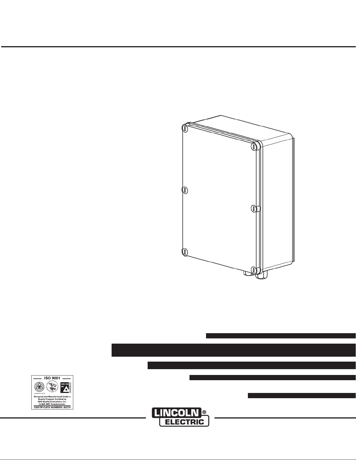
Control Box CB-WCS
RETURN TO MAIN MENU
IM10070
ay, 2010
M
For use with machines having Code Numbers:
Safety Depends on You
Lincoln arc welding and cutting
equipment is designed and built
with saf ety in mind. However,
your overall safety can be
increased by proper installation
... and thoughtful operation on
your part. DO NOT INSTALL,
OPERATE OR REPAIR THIS
EQUIPMENT WITHOUT READING THIS MANUAL AND THE
SAFETY PRECAUTIONS CONTAINED THROUGHOUT. And,
most importantly, think before
you act and be careful.
S-23271-1
Cleveland, Ohio 44117-1199 U.S.A. TEL: 216.481.8100 FAX: 216.486.1751 WEB SITE: www.lincolnelectric.com
OPERATOR’S MANUAL
Copyright © Lincoln Global Inc.
• World's Leader in Welding and Cutting Products •
• Sales and Service through Subsidiaries and Distributors Worldwide •
Page 2
i
SAFETY
WARNING
ALIFORNIA PROPOSITION 65 WARNINGS
C
Diesel engine exhaust and some of its constituents
are known to the State of California to cause cancer, birth defects, and other reproductive harm.
The Above For Diesel Engines
ARC WELDING CAN BE HAZARDOUS. PROTECT YOURSELF AND OTHERS FROM POSSIBLE SERIOUS INJURY OR DEATH.
EEP CHILDREN AWAY. PACEMAKER WEARERS SHOULD CONSULT WITH THEIR DOCTOR BEFORE OPERATING.
K
Read and understand the following safety highlights. For additional safety information, it is strongly recommended that you
purchase a copy of “Safety in Welding & Cutting - ANSI Standard Z49.1” from the American Welding Society, P.O. Box
351040, Miami, Florida 33135 or CSA Standard W117.2-1974. A Free copy of “Arc Welding Safety” booklet E205 is available
rom the Lincoln Electric Company, 22801 St. Clair Avenue, Cleveland, Ohio 44117-1199.
f
BE SURE THAT ALL INSTALLATION, OPERATION, MAINTENANCE AND REPAIR PROCEDURES ARE
PERFORMED ONLY BY QUALIFIED INDIVIDUALS.
The engine exhaust from this product contains
chemicals known to the State of California to cause
cancer, birth defects, or other reproductive harm.
The Above For Gasoline Engines
i
FOR ENGINE
powered equipment.
1.a. Turn the engine off before troubleshooting and maintenance
work unless the maintenance work requires it to be running.
____________________________________________________
1.b. Operate engines in open, well-ventilated
areas or vent the engine exhaust fumes
outdoors.
____________________________________________________
1.c. Do not add the fuel near an open f la me
welding arc or when the engine is running.
Stop the engine and allow it to cool before
refueling to prevent spilled fuel from vaporizing on conta ct with hot engine parts and
igniting. Do not spill fuel when filling tank. If
fuel is spilled, wipe it up and do not start
engine until fumes have been eliminated.
____________________________________________________
1.d. Keep all equipment safety guards, covers and devices in
position and in good repair.Keep hands, hair, clothing and
tools away from V-belts, gears, fans and all other moving
parts when starting, operating or repairing equipment.
____________________________________________________
1.e. In some cases i t may b e neces sar y to remove safet y
gu a r d s to perf o r m requi r e d m ainte n a n ce. Re m o v e
guards only when necessary and replace them when the
mai n t enanc e re q uirin g th eir r e m o val i s co m plete .
Always use the greatest care when working near moving
parts.
___________________________________________________
1.f. Do not put your hands near the engine fan.
Do not attempt to override the governor or
idler by pushing on the throttle control rods
while the engine is running.
1.h. To avoid scalding, do not remove the
radiator pressure cap when the engine is
hot.
ELECTRIC AND
MAGNETIC FIELDS
may be dangerous
2.a. Electric curr en t flowing through any conductor c au se s
localized E le ct ri c and Magn et ic Fields (EMF). Welding
current creates EMF fi el ds around welding cables and
welding machines
2.b. EMF fie lds may i nterf ere wit h some pacemak ers, and
welders having a pacemaker should consult their physician
before welding.
2.c. Exposure to EMF fields in welding may have other health
effects which are now not known.
2.d. All welders should use the following procedures in order to
minimize exposure to EMF fields from the welding circuit:
2.d.1.
Route the electrode and work cables together - Secure
them with tape when possible.
2.d.2. Nev er coi l the ele ctrode lead around your bod y.
2.d.3. Do not place your body between the electrode and
work cables. If the electrode cable is on your right
side, the work cable should also be on your right side.
___________________________________________________
1.g. To prevent accidentally starting gasoline engines while
turning the engine or welding generator during maintenance
work, disconnect the spark plug wires, distributor cap or
magneto wire as appropriate.
2.d.4. Connect the work cable to the workpiece as close as
possible to the area being welded.
2.d.5. Do not work next to welding power source.
Page 3
ii
SAFETY
ii
ELECTRIC SHOCK can
kill.
3.a. The electrode and work (or ground) circuits
are electrically “hot” when the welder is on.
Do not touch these “hot” parts with your bare
skin or wet clothin g. W ea r dry, hole-free
gloves to insulate hands.
3.b. Insulate yourself from work and ground using dry insulation.
Make certain the insulation is large enough to cover your full
area of physical contact with work and ground.
In addition to the normal safety precautions, if welding
mu s t be p e rformed unde r elec t rically haza r dous
conditions (in damp locations or while wearing wet
clothing; on metal structures such as floors, gratings or
scaffolds; when in cramped positions such as sitting,
kneeling or lying, if there is a high risk of unavoidable or
accidental contact with the workpiece or ground) use
the following equipment:
• Semiautomatic DC Constant Voltage (Wire) Welder.
• DC Manual (Stick) Welder.
• AC Welder with Reduced Voltage Control.
3.c. In semiautomatic or automatic wire welding, the electrode,
electrode reel, welding head, nozzle or semiautomatic
welding gun are also electrically “hot”.
3.d. Always be sure the work cable makes a good electrical
connection with the metal being welded. The connection
should be as close as possible to the area being welded.
3.e. Ground the work or metal to be welded to a good electrical
(earth) ground.
3.f.
Maintain the electrode holder, work clamp, welding cable and
welding machine in good, safe operating condition. Replace
damaged insulation.
3.g. Never dip the electrode in water for cooling.
3.h. Nev er simul tan eousl y touch ele ctric all y “ho t” parts of
electrode holders connected to two welders because voltage
between the two can be the total of the open circuit voltage
of both welders.
3.i. When working above floor level, use a safety belt to protect
yourself from a fall should you get a shock.
3.j. Also see Items 6.c. and 8.
ARC RAYS can burn.
4.a. Use a shield with the proper filter and cover
plates to protect your eyes from sparks and
the rays of the arc when welding or observing
open arc welding. Headshield and filter lens
should conform to ANSI Z87. I standards.
4.b. Use suitable clothing made from durable flame-resistant
material to protect your skin and that of your helpers from
the arc rays.
4.c. Protect other nearby personnel with suitable, non-flammable
screening and/or warn them not to watch the arc nor expose
themselves to the arc rays or to hot spatter or metal.
FUMES AND GASES
can be dangerous.
5.a. Weldi ng may produce fumes and gases
hazardous to health. Avoid breathing these
fumes and gases. When w elding, kee p
your head out of the fume. Use enough
ventilation and/or exhaust at the arc to keep
fumes an d gases away from the breathing zone. When
we l ding with electrod e s wh i ch re quire special
ve ntilat i on such as stainl ess or h ard facin g (see
instructio ns on container or MSDS) or on lead or
cadmium plated steel and other metals or coatings
which produce highly toxic fumes, keep exposure as
low as possible and within applicable OSHA PEL and
ACGIH TLV limits using local exhaust or mechanical
ventilation. In confined spaces or in some circumst ances, outd oors, a respir a tor may be requir e d.
Additional precautions are also required when welding
on galvanized steel.
5. b. The operation of welding fume control equipment is affected
by various factors including proper use and positioning of
the equipment, maintenance of the equipment and the specific welding procedure and application involved. Worker
exposure level should be checked upon installation and
periodically thereafter to be certain it is within applicable
OSHA PEL and ACGIH TLV limits.
5.c.
Do not weld in locations near chlorinated hydrocarbon
coming from degreasing, cleaning or spraying operations.
The heat and rays of the arc can react with solvent vapors
form phosgene, a highly toxic gas, and other irritating products.
5.d. Shielding gases used for arc welding can displace air and
caus e injur y or dea th. Alw ay s use e no ugh ven tilat io n,
especially in confined areas, to insure breathing air is safe.
vapors
to
5.e. Read and understand the manufacturer’s instructions for this
equipment and the consumables to be used, including the
mat e r ial s a f ety d a t a sh e et ( M S D S) a n d foll o w your
employer’s safety practices. MSDS forms are available from
you r wel d i n g di s t ribut o r or f rom th e ma n u factu r e r .
5.f. Also see item 1.b.
Page 4
iii
SAFETY
iii
WELDING and CUTTING
SPARKS can
cause fire or explosion.
6.a.
Remove fire hazards from the welding area.
If this is not possible, cover them to prevent
Re m e m ber th a t w eldin g s p arks a n d h ot
materials from welding can easily go through small cracks
an d o pen ings t o a djac ent area s. Avo id wel d ing near
hydraulic lines. Have a fire extinguisher readily available.
6.b. Where compressed gases are to be used at the job site,
special precautions should be used to prevent hazardous
situations. Refer to “Safety in Welding and Cutting” (ANSI
Standard Z49.1) and the op erating information for the
equipment being used.
6.c. When not welding, make certain no part of the electrode
circuit is touching the work or ground. Accidental contact
can cause overheating and create a fire hazard.
6.d. Do not heat, cut or weld tanks, drums or containers until the
proper steps have been taken to insure that such procedures
will not cause flammable or toxic vapors from substances
inside. They can cause an explosion even
been “cleaned”. For information, purchase “Recommended
Safe Practices for the
Co n t a iners and Piping That Have Held Haza r d o us
Substances”, AWS F4.1 from the American Welding Society
(see address above).
6.e. Vent hollow castings or containers before heating, cutting or
welding. They may explode.
Sparks and spatter are thrown from the welding arc. Wear oil
6.f.
free protective garments such as leather gloves, heavy shirt,
cuffless trousers, high shoes and a cap over your hair. Wear
ear plugs when welding out of position or in confined places.
Always wear safety glasses with side shields when in a
welding area.
6.g. Connect the work cable to the work as close to the welding
area as practical. Work cables connected to the building
framework or other locations away from the welding area
increase the po ss ib il it y of t he welding current passing
through lifting chains, crane cables or other alternate circuits. This can create fire hazards or overheat lifting chains
or cables until they fail.
6.h. Also see item 1.c.
the welding s pa rks fro m startin g a fire.
though
they have
Preparation
for Welding and Cutting of
CYLINDER may explode
if damaged.
7.a. Us e o n ly com p r e ssed g a s c ylind e r s
containing the correct shielding gas for the
pr o c e ss used a n d p r operl y o p erati n g
reg u l ators de signe d for t h e gas a n d
pressure used. All hoses, fittings, etc. should be suitable for
the application and maintained in good condition.
7.b. Alway s kee p cylin ders in an uprig ht pos ition s ecure ly
chained to an undercarriage or fixed support.
7.c. Cylinders should be located:
• Away from areas where they may be struck or subjected to
physical damage.
• A safe distance from arc welding or cutting operations and
any other source of heat, sparks, or flame.
7.d. Never allow the electrode, electrode holder or any other
electrically “hot” parts to touch a cylinder.
7.e. Keep your head and face away from the cylinder valve outlet
when opening the cylinder valve.
7.f. Valve protection caps should always be in place and hand
tight except when the cylinder is in use or connected for
use.
7.g. Rea d a nd follow t he ins tru cti ons on com pre sse d g as
cylinders, associated equipment, and CGA publication P-l,
“Precautions for Safe Handling of Compressed Gases in
Cylinders,” available from the Compressed Gas Association
1235 Jefferson Davis Highway, Arlington, VA 22202.
FOR ELECTRICALLY
powered equipment.
8.a. Turn off input power using the disconnect
switch at the fuse box before working on
the equipment.
8.b. In stall equipm ent in acco rdance wi th the U.S. National
Electrical Code, all local codes a nd the manufacturer’s
recommendations.
8.c. Ground the equipment in accordance with the U.S. National
Electrical Code and the manufacturer’s recommendations.
6.I. Read and follow NFPA 51B “ Standard for Fire Prevention
During Welding, Cutting and Other Hot Work”, available
from NFPA, 1 Batterymarch Park, PO box 9101, Quincy, Ma
022690-9101.
6.j. Do not use a welding power source for pipe thawing.
Refer to http://www.lincolnelectric.com/safety for additional safety information.
Page 5

iv
SAFETY
iv
PRÉCAUTIONS DE SÛRETÉ
Pour
votre propre protection lire et observer toutes les instructions
et les précautions de sûreté specifiques qui parraissent dans ce
manuel aussi bien que les précautions de sûreté générales suivantes:
Sûreté Pour Soudage A L’Arc
1. Protegez-vous contre la secousse électrique:
a. Les circuits à l’électrode et à la piéce sont sous tension
quand la machine à souder est en marche. Eviter toujours
tout contact entre les parties sous tension et la peau nue
ou les vétements mouillés. Porter des gants secs et sans
trous pour isoler les mains.
b. Faire trés attention de bien s’isoler de la masse quand on
soude dans des endroits humides, ou sur un plancher
metallique ou des grilles metalliques, principalement dans
les positions assis ou couché pour lesquelles une grande
partie du corps peut être en contact avec la masse.
c. Maintenir le porte-électrode, la pince de masse, le câble
de soudage et la machine à souder en bon et sûr état
defonctionnement.
d.Ne jamais plonger le porte-électrode dans l’eau pour le
refroidir.
e. Ne jamais toucher simultanément les parties sous tension
des porte-électrodes connectés à deux machines à souder
parce que la tension entre les deux pinces peut être le
total de la tension à vide des deux machines.
f. Si on utilise la machine à souder comme une source de
courant pour soudage semi-automatique, ces precautions
pour le porte-électrode s’applicuent aussi au pistolet de
soudage.
2. Dans le cas de travail au dessus du niveau du sol, se protéger
contre les chutes dans le cas ou on recoit un choc. Ne jamais
enrouler le câble-électrode autour de n’importe quelle partie
du corps.
5. Toujours porter des lunettes de sécurité dans la zone de
soudage. Utiliser des lunettes avec écrans lateraux dans les
zones où l’on pique le laitier.
6. Eloigner les matériaux inflammables ou les recouvrir afin de
prévenir tout risque d’incendie dû aux étincelles.
7. Quand on ne soud
la masse. U n cour t-circuit accidental peut provoquer un
échauffement et un risque d’incendie.
8. S’assurer que la masse est connectée le plus prés possible
de la zone de travail qu’il est pratique de le faire. Si on place
la masse sur la charpente de la construction ou d’autres
endroits éloignés de la zone de travail, on augmente le risque
de voir passer le courant de soudage par les chaines de levage, câbles de grue, ou autres circuits. Cela peut provoquer
des risques d’incendie ou d’echauffement des chaines et des
câbles jusqu’à ce qu’ils se rompent.
9. Assurer une ventilation suffisante dans la zone de soudage.
Ceci est particuliérement important pour le soudage de tôles
galvanisées plombées, ou cadmiées ou tout autre métal qui
produit des fumeés toxiques.
10. Ne pas souder en présence de vapeurs de chlore provenant
d’o pérations de dégraissage, nettoyage ou pistolage. La
chaleur ou les rayons de l’arc peuvent réagir avec les vapeurs
du solvant pour produire du phosgéne (gas fortement toxique)
ou autres produits irritants.
11. Pour obtenir de plus amples renseignements sur la sûreté,
voir le code “Code for safety in welding and cutting” CSA
Standard W 117.2-1974.
e pas, poser la pince à une endroit isolé de
PRÉCAUTIONS DE SÛRETÉ POUR
3. Un coup d’arc peut être plus sévère qu’un coup de soliel,
donc:
a. Utiliser un bon masque avec un verre filtrant approprié
ainsi qu’un verre blanc afin de se protéger les yeux du rayonnement de l’arc et des projections quand on soude ou
quand on regarde l’arc.
b. Porter des vêtements convenables afin de protéger la
peau de soudeur et des aides contre le rayonnement de
l‘arc.
c. Proté ge r l’autre per so nnel tra va illant à pr ox imité au
soudage à l’aide d’écrans appropriés et non-inflammables.
4. Des gout tes de laitier en fusion sont é mi ses de l’arc de
soudage. Se protéger avec des vêtements de protection libres
de l’huile, tels que les gants en cuir, chemise épaisse, pantalons sans revers, et chaussures montantes.
LES MACHINES À SOUDER À
TRANSFORMATEUR ET À
REDRESSEUR
1. Relier à la terre le chassis du poste conformement au code de
l’électricité et aux recommendations du fabricant. Le dispositif
de montage ou la piece à souder doit être branché à une
bonne mise à la terre.
2. Autant que possible, I’installation et l’entretien du poste seront
effectués par un électricien qualifié.
3. Avant de faires des travaux à l’interieur de poste, la debrancher à l’interrupteur à la boite de fusibles.
4. Garder tous les couvercles et dispositifs de sûreté à leur
place.
Page 6

SAFETY
Electromagnetic Compatibility (EMC)
Conformance
roducts displaying the CE mark are in conformity with European Community Council Directive of 15 Dec
P
2004 on the approximation of the laws of the Member States relating to electromagnetic compatibility,
2004/108/EC. It was manufactured in conformity with a national standard that implements a harmonized
standard: EN 60974-10 Electromagnetic Compatibility (EMC) Product Standard for Arc Welding Equipment.
It is for use with other Lincoln Electric equipment. It is designed for industrial and professional use.
Introduction
All electrical equipment generates small amounts of electromagnetic emission. Electrical emission may be
transmitted through power lines or radiated through space, similar to a radio transmitter. When emissions
are received by other equipment, electrical interference may result. Electrical emissions may affect many
kinds of electrical equipment; other nearby welding equipment, radio and TV reception, numerical controlled
machines, telephone systems, computers, etc. Be aware that interference may result and extra precautions
may be required when a welding power source is used in a domestic establishment.
Installation and Use
The user is responsible for installing and using the welding equipment according to the manufacturer’s
instructions. If electromagnetic disturbances are detected then it shall be the responsibility of the user of the
welding equipment to resolve the situation with the technical assistance of the manufacturer. In some cases
this remedial action may be as simple as earthing (grounding) the welding circuit, see Note. In other cases it
could involve construction of an electromagnetic screen enclosing the power source and the work complete
with associated input filters. In all cases electromagnetic disturbances must be reduced to the point where
they are no longer troublesome.
vv
Note: The welding circuit may or may not be earthed for safety reasons according to national codes.
Changing the earthing arrangements should only be authorized by a person who is competent to access whether the changes will increase the risk of injury, e.g., by allowing parallel
welding current return paths which may damage the earth circuits of other equipment.
Assessment of Area
Before installing welding equipment the user shall make an assessment of potential electromagnetic problems in the surrounding area. The following shall be taken into account:
a) other supply cables, control cables, signaling and telephone cables; above, below and adjacent to the
welding equipment;
b) radio and television transmitters and receivers;
c) computer and other control equipment;
d) safety critical equipment, e.g., guarding of industrial equipment;
e) the health of the people around, e.g., the use of pacemakers and hearing aids;
f) equipment used for calibration or measurement
g) the immunity of other equipment in the environment. The user shall ensure that other equipment being
used in the environment is compatible. This may require additional protection measures;
h) the time of day that welding or other activities are to be carried out.
Page 7

SAFETY
Electromagnetic Compatibility (EMC)
The size of the surrounding area to be considered will depend on the structure of the building and other
ctivities that are taking place. The surrounding area may extend beyond the boundaries of the premises.
a
Methods of Reducing Emissions
Mains Supply
Welding equipment should be connected to the mains supply according to the manufacturer’s recommendations. If interference occurs, it may be necessary to take additional precautions such as filtering of the mains
supply. Consideration should be given to shielding the supply cable of permanently installed welding equipment, in metallic conduit or equivalent. Shielding should be electrically continuous throughout its length. The
shielding should be connected to the welding power source so that good electrical contact is maintained
between the conduit and the welding power source enclosure.
Maintenance of the Welding Equipment
The welding equipment should be routinely maintained according to the manufacturer’s recommendations.
All access and service doors and covers should be closed and properly fastened when the welding equipment is in operation. The welding equipment should not be modified in any way except for those changes
and adjustments covered in the manufacturers instructions. In particular, the spark gaps of arc striking and
stabilizing devices should be adjusted and maintained according to the manufacturer’s recommendations.
vivi
Welding Cables
The welding cables should be kept as short as possible and should be positioned close together, running at
or close to floor level.
Equipotential Bonding
Bonding of all metallic components in the welding installation and adjacent to it should be considered.
However, metallic components bonded to the work piece will increase the risk that the operator could
receive a shock by touching these metallic components and the electrode at the same time. The operator
should be insulated from all such bonded metallic components.
Earthing of the Workpiece
Where the workpiece is not bonded to earth for electrical safety, not connected to earth because of its size
and position, e.g., ships hull or building steelwork, a connection bonding the workpiece to earth may reduce
emissions in some, but not all instances. Care should be taken to prevent the earthing of the workpiece
increasing the risk of injury to users, or damage to other electrical equipment. Where necessary, the connection of the workpiece to earth should be made by a direct connection to the workpiece, but in some countries
where direct connection is not permitted, the bonding should be achieved by suitable capacitance, selected
according to national regulations.
Screening and Shielding
Selective screening and shielding of other cables and equipment in the surrounding area may alleviate problems of interference. Screening of the entire welding installation may be considered for special applications.
1
_________________________
1
Portions of the preceding text are contained in EN 60974-10: “Electromagnetic Compatibility (EMC) product standard for arc welding equipment.”
Page 8

ii
v
Thank You
v
for selecting a QUALITY product by Lincoln Electric. We want you
to take pride in operating this Lincoln Electric Company product
••• as much pride as we have in bringing this product to you!
ii
The business of The Lincoln Electric Company is manufacturing and selling high quality welding equipment, consumables, and cutting equipment. Our challenge is to meet the needs of our customers and to exceed their expectations. On occasion, purchasers may ask Lincoln
Electric for advice or information about their use of our products. We respond to our customers based on the best information in our possession at that time. Lincoln Electric is not in a position to warrant or guarantee such advice, and assumes no liability, with respect to such information or advice. We expressly disclaim any warranty of any kind, including any warranty of fitness for any customer’s particular purpose,
with respect to such information or advice. As a matter of practical consideration, we also cannot assume any responsibility for updating or
correcting any such information or advice once it has been given, nor does the provision of information or advice create, expand or alter any
warranty with respect to the sale of our products.
Lincoln Electric is a responsive manufacturer, but the selection and use of specific products sold by Lincoln Electric is solely within the control
of, and remains the sole responsibility of the customer. Many variables beyond the control of Lincoln Electric affect the results obtained in
applying these types of fabrication methods and service requirements.
Subject to Change – This information is accurate to the best of our knowledge at the time of printing. Please refer to www.lincolnelectric.com
for any updated information.
CUSTOMER ASSISTANCE POLICY
Please Examine Carton and Equipment For Damage Immediately
When this equipment is shipped, title passes to the purchaser upon receipt by the carrier. Consequently, Claims
for material damaged in shipment must be made by the purchaser against the transportation company at the
time the shipment is received.
Please record your equipment identification information below for future reference. This information can be
found on your machine nameplate.
Product _________________________________________________________________________________
Model Number ___________________________________________________________________________
Code Number or Date Code_________________________________________________________________
Serial Number____________________________________________________________________________
Date Purchased___________________________________________________________________________
Where Purchased_________________________________________________________________________
Whenever you request replacement parts or information on this equipment, always supply the information you
have recorded above. The code number is especially important when identifying the correct replacement parts.
On-Line Product Registration
- Register your machine with Lincoln Electric either via fax or over the Internet.
• For faxing: Complete the form on the back of the warranty statement included in the literature packet
accompanying this machine and fax the form per the instructions printed on it.
• For On-Line Registration: Go to our
“Product Registration”. Please complete the form and submit your registration.
Read this Operators Manual completely before attempting to use this equipment. Save this manual and keep it
handy for quick reference. Pay particular attention to the safety instructions we have provided for your protection.
The level of seriousness to be applied to each is explained below:
WEB SITE at www.lincolnelectric.com. Choose “Quick Links” and then
WARNING
This statement appears where the information must be followed exactly to avoid serious personal injury or loss of life.
CAUTION
This statement appears where the information must be followed to avoid minor personal injury or damage to this equipment.
Page 9

TABLE OF CONTENTS
PREFACE ................................................................................................................................................... 2
1 INTRODUCTION ................................................................................................................................. 2
1.1 Identification of the Product ....................................................................................................... 2
1.2 General Description .................................................................................................................. 2
1.3 Product Combinations ............................................................................................................... 2
1.4 Technical Specifications ........................................................................................................... 2
2 PRODUCT DESCRIPTION ................................................................................................................. 3
2.1 Components .............................................................................................................................. 3
2.2 Operation .................................................................................................................................. 3
3 SAFETY .............................................................................................................................................. 3
4 INSTALLATION .................................................................................................................................. 4
4.1 Unpacking ................................................................................................................................. 4
4.2 Installation ................................................................................................................................. 4
4.3 Electric connection ................................................................................................................... 4
4.3.1 Mains (“MAINS”) ............................................................................................................................. 4
4.3.2 Extraction fan (“FAN MOTOR”) .......................................................................................................4
4.3.3 Automatic start/stop device (WCS) (“WCS”) ...................................................................................5
4.3.4 Work Lamp (WL) and/or Arc Sensor (AST) (“WCS”) ......................................................................5
4.3.5 Stationary welding fume extractor (Statiflex 400-MS) (“FILTER”) ............................................... ... .5
4.4 Adjustment ................................................................................................................................ 5
4.4.6 Start delay .......................................................................................................................................5
4.4.7 Stop delay .............................. ... .. ....................................................................................................5
Page
5 OPERATION ....................................................................................................................................... 5
6 MAINTENANCE .................................................................................................................................. 5
7 TROUBLESHOOTING ........................................................................................................................ 6
8 SPARE PARTS ................................................................................................................................... 7
9 DISPOSAL .......................................................................................................................................... 7
10 ELECTRICAL DIAGRAM ................................................................................................................... 8
CONTROL BOX CB-WCS
Page 10

PREFACE
Using this Instruction Manual
This instruction manual is intended to be used as a work of
reference for professional, well trained and authorized users
to be able to safely install, use, maintain and repair the
product mentioned on the cover of this document.
Always keep this manual with the product.
Pictograms and Symbols
The following pictograms and symbols are used in this
manual:
TIP
Suggestions and recommendations to simplify
carrying out tasks and actions.
•product name
• serial number
• supply voltage and frequency
• power consumption
1.2 General Description
The CB-WCS is a control box to:
• connect the automatic start/stop device WCS to the
mains
• switch the connected extraction fan SF 2400 on and off
by the automatic start/stop device WCS
The CB-WCS can also be used for connecting a stationary
welding fume extractor Statiflex 400-MS, an in the extraction
arm integrated Work Lamp (WL) and/or automatic start/stop
device (AST or WCS) and an extraction fan (SF 2400) to the
mains.
ATTENTION!
Remark with additional information for the user. A
remark brings a possible problem to the user’s
attention.
CAUTION!
This statement appears where the instructions
must be followed to avoid minor personal injury
or damage to this equipment.
WARNING!
This statement appears where the instructions
must be followed exactly to avoid serious
personal injury or loss of life.
CAUTION!
Denotes risk of electric shock.
Service and Technical Support
For information about specific adjustments, maintenance or
repair jobs which are not dealt with in this manual, please
contact the supplier of the product. Make sure you have the
following data on hand:
- product name
- serial number
- purchase order (number + date) for warranty verification
1.3 Product Combinations
The CB-WCS can be used with the following products:
• S23274-2 Welding cable sensor WCS
• K1656-1 Extraction fan SF 2400 (115V/1ph/60Hz)
1.4 Technical Specifications
CB-WCS
Product part # S-23271-1
Dimensions refer to Fig. 1.1
Weight 3.9 kg (8.6 lbs)
Isolation class IP 55
Operating temperature:
- minimum
- nominal
- maximum
Max. relative humidity 80%
-5°C (41°F)
- 20°C (68°F)
- 45°C (113°F)
The product name and serial number can be found on the
identification label located at the cover of the control box.
1 INTRODUCTION
1.1 Identification of the Product
The identification label contains the following data:
CONTROL BOX CB-WCS
Fig. 1.1: Dimensions
Page 11

2 PRODUCT DESCRIPTION
2.1 Components
The CB-WCS consists of the following components (Fig.
2.1):
A Cover
BHousing
C Timer PC board
D Fuse 2A
E Connecting block
F Transformer
G Thermal relay
HRelay
I Fuse holder
J Main fuse
K Cap nut
L Cable gland
maintenance and repair of the product mentioned on the
cover of this document and any corresponding accessories.
Specific working conditions or used accessories may
require additional safety instructions. Immediately contact
your supplier if you detect a potential hazard when using the
product.
User Manual
• Everyone working on or with the product must be familiar
with the contents of this manual and must strictly observe
the instructions herein. Management should instruct and
train the operators in accordance with the manual and
observe all instructions and directions given.
• Never change the order of steps-to-be-performed.
• Always keep the manual with the product.
Users
The use of this product is exclusively reserved to authorized,
trained and qualified users. Temporary personnel and
personnel in training can only use the product under
supervision and responsibility of management and trained
personnel such as skilled engineers.
CAUTION!
The user of the product is always fully responsible
for observing the local safety instructions and
regulations.
Fig. 2.1: Main components
2.2 Operation
The CB-WCS is a control box which supplies power to the
connected welding cable sensor WCS and extraction fan SF
2400. The CB-WCS arranges the extraction fan to switch on
and off automatically. To realise this, the WCS is to be
connected to the ground cable of a welding machine. When
the welding starts, the WCS sends a signal to the CB-WCS.
Subsequently, the extraction fan SF 2400 automatically
switches on. When the welding stops, the fan automatically
switches off. Depending on the specific circumstances and/
or the user’s wish, the start delay and the stop delay of the
fan can be adjusted.
3SAFETY
General
The manufacturer does not accept any liability for damage
to the product or personal injury caused by non-observance
of the safety instructions in this manual, modifications made
to equipment or by negligence during installation, use,
Intended Use1
The product has been designed exclusively to switch the
connected extraction fan on and off by the automatic start/
stop device WCS and to connect the WCS to the mains.
Using the product for other purposes is considered contrary
to its intended use. The manufacturer accepts no liability for
any damage or injury resulting from such use. The product
has been built in accordance with state-of-the-art standards
and recognized safety regulations. Only use the product in
mechanically sound condition in accordance with its
intended use and the instructions set forth in the user
manual.
Modifications
Modifications of this product, other than those specified in
this manual, are not allowed. Any unauthorized modification
will void the product warranty.
Use
If the product is used in combination with the in the
introduction of this manual mentioned products or machines
(see 1.3), the safety instruction in the documentation of
these products also apply.
1. "Intended use" as laid down in EN-292-1 is the use for which the technical product
is suited as specified by the manufacturer, inclusive of his directions in the sales
brochure. In case of doubt it is the use which can be deducted from the
construction, the model and the function of the technical product which is
considered normal use. Operating the machine within the limits of its intended use
also involves observing the instructions in the user manual.
CONTROL BOX CB-WCS
Page 12

• Only use the product in technically perfect condition.
• Inspect the product and check it for damage.
• Protect the product against water and humidity.
• Never use the product in an explosive environment.
• Make sure that the facility contains sufficient approved
fire extinguishers.
Service, Maintenance and Repairs
CAUTION!
Service and repair should only be performed by
Lincoln Electric Factory Trained Personnel.
• Always use tools, materials, lubricants and service
techniques which have been approved by the
manufacturer. Never use worn tools and do not leave any
tools in or on the product.
Fig. 4.1: Installation CB-WCS
4.3 Electric connection
4 INSTALLATION
WARNING!
The installer is responsible for following federal,
state and local safety codes and regulations.
4.1 Unpacking
Check that the product package is complete. The package
should contain:
• (1) fully premounted and wired CB-WCS (transformer,
relay, timer PC board with fuse and connection block)
• (1) instruction manual
• (1) instruction manual
If parts are missing or damaged, contact your supplier.
4.2 Installation
ATTENTION!
Do not position the CB-WCS where it is exposed to
vibrations or heat radiation from heat sources.
Oberse the earlier described ambient conditions.
CAUTION!
Electrical connection to be carried out in
accordance with the National Electrical Code
(NEC) and local requirements. This is strictly
reserved for skilled and authorised service
engineers.
Connection Steps:
1) Connect the CB-WCS electrically to:
- mains (“MAINS”)
- extraction fan SF 2400 (“FAN MOTOR”)
- automatic start/stop device (WCS) (“WCS”)
or:
- working lamp (WL) and/or Arc Sensor (AST) (“WCS”)
- stationary welding fume extractor (Statiflex 400-MS)
(“FILTER”)
CAUTION!
Make sure that the system is suitable for
connection to the local mains. Information about
the connection voltage and frequency can be found
on the identification plate. The cables must be
connected in conformance with the local rules and
regulations and can only be carried out by well
qualified and authorised technicians.
ATTENTION!
Before drilling, verify locations of existing gas,
water or electrical conduits.
Installation Steps:
Use Fig. 4.1 for steps 1-2
1) Loosen the mounting screws (C) and remove the cover
(D).
2) The housing (A) is provided with mounting holes (B).
Use these to attach the housing to the wall by means of
four bolts.
CONTROL BOX CB-WCS
4.3.1 Mains (“MAINS”)
2) Feed the mains cord through the cable gland (“MAINS”)
and connect it in accordance with the also supplied
electric diagram.
3) Interconnect the black wire.
4) Tighten the cap nut.
4.3.2 Extraction fan (“FAN MOT OR”)
5) Feed the supply cable of the extraction fan through the
cable gland (“FAN MOTOR”) and connect the cable in
accordance with the also supplied electric diagram.
Page 13

5) Tighten the cap nut.
4.3.3 Automatic start/stop device (WCS) (“WCS”)
7) Feed the supply cable of the WCS through the cable
gland (“WCS”) and connect the cable in accordance
with the also supplied electric diagram.
8) Tighten the cap nut.
4.3.4 Work Lamp (WL) and/or Arc Sensor (AST)
(“WCS”)
9) Feed the supply cable (NCW 11) through the cable
gland (“WCS”) and connect the cable to the timer PC
board in accordance with the also supplied electric
diagram.
10) Tighten the cap nut.
Fig. 4.2: Timer PC board
If applicable:
4.3.5 Stationary welding fume extractor (Statiflex 400-
MS) (“FILTER”)
11) Feed the suply cable through the cable gland
(“FILTER”) and connect the cable as described in the
corresponding manual.
12) Tighten the cap nut.
Use Fig. 4.1 for steps 13
13) Apply the cover (D) and fix it by the mounting screws
(C).
4.4 Adjustment
The standard start delay and the standard stop delay of the
extraction fan(s) are 0 seconds. This means that the
connected fan will immediately start running when the
welding starts and will stop immediately after the (last)
welder is finished. If desired, these pre-set times can be
adjusted by changing the settings of the timer PC board (Fig.
4.2). The timer PC board consists of the following
components:
A Potmeter 1 (start delay)
B Potmeter 2 (stop delay)
CStatus leds
D Fuse 2A
E Connection WCS, AST, Filter
F Connection 24 VAC
G Relay contact
4.4.1 Start delay
The start delay can be set from 0 to 5 seconds (standard 0
seconds). To adjust the start delay, proceed as follows.
• Adjust Potmeter 1 (Fig. 4.2A) to the desired number of
seconds.
4.4.2 Stop delay
The stop delay can be set from 0 to 300 seconds (standard
0 seconds). To adjust the stop delay, proceed as follows.
• Adjust Potmeter 2 (Fig. 4.2B) to the desired number of
seconds.
In most cases, a stop delay of 20 seconds will be
sufficient.
When setting the installation, the functioning of the timer PC
board can be checked by the status leds Power, Input and
Output (Fig. 4.2C) on the timer PC board.
5OPERATION
By applying the weldling cable sensor WCS to the ground
cable of a welding machine, the CB-WCS functions fully
automatically.
6 MAINTENANCE
The CB-WCS does not require any specific maintenance.
CONTROL BOX CB-WCS
Page 14

7 TROUBLESHOOTING
Observe all safety guidelines detailed throughout this
instruction manual.
Step 1: Symptom
The first column labeled “Symptom” describes possible
symptoms that the machine may exhibit. Find the listing that
best describes the symptoms that the machine is exhibiting.
A number problems in the checklist below can also
be caused by defects in the connected equipment.
This manual mainly deals with problems and
solutions directly related to the product itself.
WARNING!
Service and repair should only be performed by
Lincoln Electric Factory Trained Personnel.
Unauthorized repairs performed on this equipment
may result in danger to the technician and machine
operator and will invalidate your factory warranty.
For your safety and to avoid electrical shock,
please observe all safety notes and precautions
detailed throughout this instruction manual.
This troubleshooting guide is provided to help you locate
and repair possible machine malfunctions. Simply follow the
four-step procedure listed below.
Table 1: Troubleshooting guide
Symptom Problem Possible Cause Solution
No extraction when
welding starts.
Fan keeps running
without welding
activities.
Fan motor does not
start.
Sensor of WCS not
activated.
Sensor
malfunctioning.
Power supply failing. Fuse in CB-WCS broken. Check fuse and try to determine why
Delay timer. Start delay timer activated. Please see if you want the start delay
Sensor. Sensor defective. Check sensor function with a small
Delay timer. Stop delay timer activated (0-5
Arc sensor in use. AST has its own delay time with a
Thermal breaker activated. Reset thermal breaker.
No power connected to the CB-WCS. Check power supply.
Sensor defective. Check sensor function with a small
Sensor not connected to the ground
cable of the welding machine.
Sensor broken. Check sensor input on circuit board.
minutes).
minimum of 12 seconds stop delay
and a maximum of 2 minutes.
Step 2: Locate Problem
The second column “Problem” describes the possible
consequences of the found symptom.
Step 3: Possible Cause
The third column labeled “Possible cause” lists the obvious
external possibilities that may contribute to the machine
symptom.
Step 4: Solution
The fourth column labeled “Solution” provides a course of
action for the possible cause. Generally it states to contact
your local Lincoln Authorized Field Service Facility.
CAUTION!
If for any reason you do not understand the test
procedures or are unable to safely perform the
tests and repairs, contact your Local Lincoln
Authorized Field Service Facility for technical
troubleshooting assitance before you proceed.
magnet. Red LED should lit on the
sensor.
Connect sensor to the ground cable
of the welding machine.
Input LED should be lit when the
sensor LED is activated
the fuse blew (e.g. short circuit) and
repair.
timer to be active.
magnet. Red LED should lit on the
sensor.
Please see if you want the stop delay
timer to be active.
See if you need to change the delay
time in the AST sensor.
CONTROL BOX CB-WCS
Page 15

8 SPARE PARTS
The available spare parts for the control box are indicated on
the exploded views.
Address your order to your supplier and always state the
data below:
- product name and serial number (see the identification
label)
- article number of the particular part
- description
- quantity
Table 2: Spare parts
Item/Description Part # Qty
A Timer print 0326730020 1
B Fuse 2A 1
C Connection block + wire beam 0308400620 1
D Transformer 45VA 0334200170 1
E Relay 0328410120 1
F Themal relay 0328400170 1
G Fuse holder 0340520040 1
H Main fuse 0340010100 1
Fig. 8.1: Exploded view
9 DISPOSAL
After life of the product, dispose it of in accordance with
federal, state or local regulations.
CONTROL BOX CB-WCS
Page 16

10 ELECTRICAL DIAGRAM
CONTROL BOX CB-WCS
Page 17

NOTES
Page 18

WARNING
Spanish
AVISO DE
PRECAUCION
• Do not touch electrically live parts or
electrode with skin or wet clothing.
• Insulate yourself from work and
ground.
• No toque las partes o los electrodos
bajo carga con la piel o ropa mojada.
• Aislese del trabajo y de la tierra.
• Keep flammable materials away.
• Mantenga el material combustible
fuera del área de trabajo.
• Wear eye, ear and body protection.
• Protéjase los ojos, los oídos y el
cuerpo.
French
ATTENTION
erman
G
WARNUNG
Portuguese
ATENÇÃO
Japanese
Chinese
Korean
Arabic
• Ne laissez ni la peau ni des vête-
ments mouillés entrer en contact
avec des pièces sous tension.
• Isolez-vous du travail et de la terre.
• Berühren Sie keine stromführenden
Teile oder Elektroden mit Ihrem
Körper oder feuchter Kleidung!
• Isolieren Sie sich von den
Elektroden und dem Erdboden!
• Não toque partes elétricas e electro-
dos com a pele ou roupa molhada.
• Isole-se da peça e terra.
• Gardez à l’écart de tout matériel
inflammable.
• Entfernen Sie brennbarres Material!
• Mantenha inflamáveis bem guarda-
dos.
• Protégez vos yeux, vos oreilles et
votre corps.
• Tragen Sie Augen-, Ohren- und Kör-
perschutz!
• Use proteção para a vista, ouvido e
corpo.
READ AND UNDERSTAND THE MANUFACTURER’S INSTRUCTION FOR THIS EQUIPMENT AND THE
CONSUMABLES TO BE USED AND FOLLOW YOUR EMPLOYER’S SAFETY PRACTICES.
SE RECOMIENDA LEER Y ENTENDER LAS INSTRUCCIONES DEL FABRICANTE PARA EL USO DE
ESTE EQUIPO Y LOS CONSUMIBLES QUE VA A UTILIZAR, SIGA LAS MEDIDAS DE SEGURIDAD DE
SU SUPERVISOR.
LISEZ ET COMPRENEZ LES INSTRUCTIONS DU FABRICANT EN CE QUI REGARDE CET EQUIPMENT
ET LES PRODUITS A ETRE EMPLOYES ET SUIVEZ LES PROCEDURES DE SECURITE DE VOTRE
EMPLOYEUR.
LESEN SIE UND BEFOLGEN SIE DIE BETRIEBSANLEITUNG DER ANLAGE UND DEN ELEKTRODENEINSATZ DES HERSTELLERS. DIE UNFALLVERHÜTUNGSVORSCHRIFTEN DES ARBEITGEBERS
SIND EBENFALLS ZU BEACHTEN.
Page 19

• Keep your head out of fumes.
• Use ventilation or exhaust to
remove fumes from breathing zone.
• Los humos fuera de la zona de res-
piración.
• Mantenga la cabeza fuera de los
humos. Utilice ventilación o
aspiración para gases.
• Gardez la tête à l’écart des fumées.
• Utilisez un ventilateur ou un aspira-
teur pour ôter les fumées des zones
de travail.
• Vermeiden Sie das Einatmen von
Schweibrauch!
• Sorgen Sie für gute Be- und
Entlüftung des Arbeitsplatzes!
• Turn power off before servicing.
• Desconectar el cable de ali-
mentación de poder de la máquina
antes de iniciar cualquier servicio.
• Débranchez le courant avant l’entre-
tien.
• Strom vor Wartungsarbeiten
abschalten! (Netzstrom völlig öffnen;
Maschine anhalten!)
• Do not operate with panel open or
guards off.
• No operar con panel abierto o
guardas quitadas.
• N’opérez pas avec les panneaux
ouverts ou avec les dispositifs de
protection enlevés.
• Anlage nie ohne Schutzgehäuse
oder Innenschutzverkleidung in
Betrieb setzen!
WARNING
panish
S
AVISO DE
PRECAUCION
French
ATTENTION
erman
G
WARNUNG
• Mantenha seu rosto da fumaça.
• Use ventilação e exhaustão para
remover fumo da zona respiratória.
•
Não opere com as tampas removidas.
•
Desligue a corrente antes de fazer
serviço.
•
Não toque as partes elétricas nuas.
• Mantenha-se afastado das partes
moventes.
• Não opere com os paineis abertos
ou guardas removidas.
Portuguese
ATENÇÃO
Japanese
Chinese
Korean
Arabic
LEIA E COMPREENDA AS INSTRUÇÕES DO FABRICANTE PARA ESTE EQUIPAMENTO E AS PARTES
DE USO, E SIGA AS PRÁTICAS DE SEGURANÇA DO EMPREGADOR.
Page 20

• World's Leader in Welding and Cutting Products •
• Sales and Service through Subsidiaries and Distributors Worldwide •
Cleveland, Ohio 44117-1199 U.S.A. TEL: 216.481.8100 FAX: 216.486.1751 WEB SITE: www.lincolnelectric.com
 Loading...