

Page 1
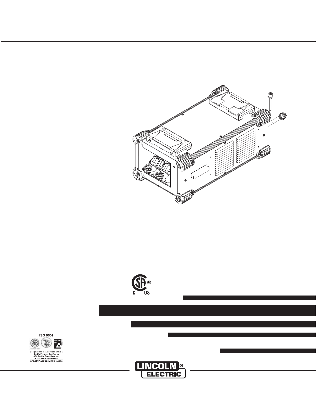
POWER WAVE®STT®MODULE
RETURN TO MAIN MENU
For use with machines having Code Numbers:
Safety Depends on You
Lincoln arc welding and cutting
equipment is designed and built
with safety in mind. However,
your overall safety can be
increased by proper installation
... and thoughtful operation on
your part. DO NOT INSTALL,
OPERATE OR REPAIR THIS
EQUIPMENT WITHOUT READING THIS MANUAL AND THE
SAFETY PRECAUTIONS CONTAINED THROUGHOUT. And,
most importantly, think before
you act and be careful.
11690
IM10058
August, 2011
Cleveland, Ohio 44117-1199 U.S.A. TEL: 216.481.8100 FAX: 216.486.1751 WEB SITE: www.lincolnelectric.com
OPERATOR’S MANUAL
Copyright © Lincoln Global Inc.
• World's Leader in Welding and Cutting Products •
• Sales and Service through Subsidiaries and Distributors Worldwide •
Page 2
i
SAFETY
i
WARNING
CALIFORNIA PROPOSITION 65 WARNINGS
Diesel engine exhaust and some of its constituents
are known to the State of California to cause cancer, birth defects, and other reproductive harm.
The Above For Diesel Engines
ARC WELDING CAN BE HAZARDOUS. PROTECT YOURSELF AND OTHERS FROM POSSIBLE SERIOUS INJURY OR DEATH.
KEEP CHILDREN AWAY. PACEMAKER WEARERS SHOULD CONSULT WITH THEIR DOCTOR BEFORE OPERATING.
Read and understand the following safety highlights. For additional safety information, it is strongly recommended that you
purchase a copy of “Safety in Welding & Cutting - ANSI Standard Z49.1” from the American Welding Society, P.O. Box
351040, Miami, Florida 33135 or CSA Standard W117.2-1974. A Free copy of “Arc Welding Safety” booklet E205 is available
from the Lincoln Electric Company, 22801 St. Clair Avenue, Cleveland, Ohio 44117-1199.
BE SURE THAT ALL INSTALLATION, OPERATION, MAINTENANCE AND REPAIR PROCEDURES ARE
PERFORMED ONLY BY QUALIFIED INDIVIDUALS.
The engine exhaust from this product contains
chemicals known to the State of California to cause
cancer, birth defects, or other reproductive harm.
The Above For Gasoline Engines
FOR ENGINE
powered equipment.
1.a. Turn the engine off before troubleshooting and maintenance
work unless the maintenance work requires it to be running.
____________________________________________________
1.b. Operate engines in open, well-ventilated
areas or vent the engine exhaust fumes
outdoors.
____________________________________________________
1.c. Do not add the fuel near an open flame
welding arc or when the engine is running.
Stop the engine and allow it to cool before
refueling to prevent spilled fuel from vaporizing on contact with hot engine parts and
igniting. Do not spill fuel when filling tank. If
fuel is spilled, wipe it up and do not start
engine until fumes have been eliminated.
____________________________________________________
1.d. Keep all equipment safety guards, covers and devices in
position and in good repair.Keep hands, hair, clothing and
tools away from V-belts, gears, fans and all other moving
parts when starting, operating or repairing equipment.
____________________________________________________
1.e. In some cases it may be necessary to remove safety
guards to perform required maintenance. Remove
guards only when necessary and replace them when the
maintenance requiring their removal is complete.
Always use the greatest care when working near moving
parts.
___________________________________________________
1.f. Do not put your hands near the engine fan.
Do not attempt to override the governor or
idler by pushing on the throttle control rods
while the engine is running.
1.h. To avoid scalding, do not remove the
radiator pressure cap when the engine is
hot.
ELECTRIC AND
MAGNETIC FIELDS
may be dangerous
2.a. Electric current flowing through any conductor causes
localized Electric and Magnetic Fields (EMF). Welding
current creates EMF fields around welding cables and
welding machines
2.b. EMF fields may in ter fer e wi th s ome pac ema kers, and
welders having a pacemaker should consult their physician
before welding.
2.c. Exposure to EMF fields in welding may have other health
effects which are now not known.
2.d. All welders should use the following procedures in order to
minimize exposure to EMF fields from the welding circuit:
2.d.1.
Route the electrode and work cables together - Secure
them with tape when possible.
2.d.2. Never coil the electrode lead around your body.
2.d.3. Do not place your body between the electrode and
work cables. If the electrode cable is on your right
side, the work cable should also be on your right side.
___________________________________________________
1.g. To prevent accidentally starting gasoline engines while
turning the engine or welding generator during maintenance
work, disconnect the spark plug wires, distributor cap or
magneto wire as appropriate.
2.d.4. Connect the work cable to the workpiece as close as
possible to the area being welded.
2.d.5. Do not work next to welding power source.
Page 3
ii
SAFETY
ii
ELECTRIC SHOCK can
kill.
3.a. The electrode and work (or ground) circuits
are electrically “hot” when the welder is on.
Do not touch these “hot” parts with your bare
skin or wet clothing. Wear dry, hole-free
gloves to insulate hands.
3.b. Insulate yourself from work and ground using dry insulation.
Make certain the insulation is large enough to cover your full
area of physical contact with work and ground.
In addition to the normal safety precautions, if welding
must be performed under electrically hazardous
conditions (in damp locations or while wearing wet
clothing; on metal structures such as floors, gratings or
scaffolds; when in cramped positions such as sitting,
kneeling or lying, if there is a high risk of unavoidable or
accidental contact with the workpiece or ground) use
the following equipment:
• Semiautomatic DC Constant Voltage (Wire) Welder.
• DC Manual (Stick) Welder.
• AC Welder with Reduced Voltage Control.
3.c. In semiautomatic or automatic wire welding, the electrode,
electrode reel, welding head, nozzle or semiautomatic
welding gun are also electrically “hot”.
3.d. Always be sure the work cable makes a good electrical
connection with the metal being welded. The connection
should be as close as possible to the area being welded.
3.e. Ground the work or metal to be welded to a good electrical
(earth) ground.
3.f.
Maintain the electrode holder, work clamp, welding cable and
welding machine in good, safe operating condition. Replace
damaged insulation.
3.g. Never dip the electrode in water for cooling.
3.h. Never simultaneously touch electrically “hot” parts of
electrode holders connected to two welders because voltage
between the two can be the total of the open circuit voltage
of both welders.
3.i. When working above floor level, use a safety belt to protect
yourself from a fall should you get a shock.
3.j. Also see Items 6.c. and 8.
ARC RAYS can burn.
4.a. Use a shield with the proper filter and cover
plates to protect your eyes from sparks and
the rays of the arc when welding or observing
open arc welding. Headshield and filter lens
should conform to ANSI Z87. I standards.
4.b. Use suitable clothing made from durable flame-resistant
material to protect your skin and that of your helpers from
the arc rays.
4.c. Protect other nearby personnel with suitable, non-flammable
screening and/or warn them not to watch the arc nor expose
themselves to the arc rays or to hot spatter or metal.
FUMES AND GASES
can be dangerous.
5.a. Welding may produce fumes and gases
hazardous to health. Avoid breathing these
fumes and gases. When welding, keep
your head out of the fume. Use enough
ventilation and/or exhaust at the arc to keep
fumes and gases away from the breathing zone. When
welding with electrodes which require special
ventilation such as stainless or hard facing (see
instructions on container or MSDS) or on lead or
cadmium plated steel and other metals or coatings
which produce highly toxic fumes, keep exposure as
low as possible and within applicable OSHA PEL and
ACGIH TLV limits using local exhaust or mechanical
ventilation. In confined spaces or in some circumstances, outdoors, a respirator may be required.
Additional precautions are also required when welding
on galvanized steel.
5. b. The operation of welding fume control equipment is affected
by various factors including proper use and positioning of
the equipment, maintenance of the equipment and the specific welding procedure and application involved. Worker
exposure level should be checked upon installation and
periodically thereafter to be certain it is within applicable
OSHA PEL and ACGIH TLV limits.
5.c.
Do not weld in locations near chlorinated hydrocarbon
coming from degreasing, cleaning or spraying operations.
The heat and rays of the arc can react with solvent vapors
form phosgene, a highly toxic gas, and other irritating products.
5.d. Shielding gases used for arc welding can displace air and
cause injury or death. Always use enough ventilation,
especially in confined areas, to insure breathing air is safe.
vapors
to
5.e. Read and understand the manufacturer’s instructions for this
equipment and the consumables to be used, including the
material safety data sheet (MSDS) and follow your
employer’s safety practices. MSDS forms are available from
your welding distributor or from the manufacturer.
5.f. Also see item 1.b.
Page 4
iii
SAFETY
iii
WELDING and CUTTING
SPARKS can
cause fire or explosion.
6.a.
Remove fire hazards from the welding area.
If this is not possible, cover them to prevent
Remember that welding sparks and hot
materials from welding can easily go through small cracks
and openings to adjacent areas. Avoid welding near
hydraulic lines. Have a fire extinguisher readily available.
6.b. Where compressed gases are to be used at the job site,
special precautions should be used to prevent hazardous
situations. Refer to “Safety in Welding and Cutting” (ANSI
Standard Z49.1) and the operating information for the
equipment being used.
6.c. When not welding, make certain no part of the electrode
circuit is touching the work or ground. Accidental contact
can cause overheating and create a fire hazard.
6.d. Do not heat, cut or weld tanks, drums or containers until the
proper steps have been taken to insure that such procedures
will not cause flammable or toxic vapors from substances
inside. They can cause an explosion even
been “cleaned”. For information, purchase “Recommended
Safe Practices for the
Containers and Piping That Have Held Hazardous
Substances”, AWS F4.1 from the American Welding Society
(see address above).
6.e. Vent hollow castings or containers before heating, cutting or
welding. They may explode.
Sparks and spatter are thrown from the welding arc. Wear oil
6.f.
free protective garments such as leather gloves, heavy shirt,
cuffless trousers, high shoes and a cap over your hair. Wear
ear plugs when welding out of position or in confined places.
Always wear safety glasses with side shields when in a
welding area.
6.g. Connect the work cable to the work as close to the welding
area as practical. Work cables connected to the building
framework or other locations away from the welding area
increase the possibility of the welding current passing
through lifting chains, crane cables or other alternate circuits. This can create fire hazards or overheat lifting chains
or cables until they fail.
6.h. Also see item 1.c.
the welding sparks from starting a fire.
though
they have
Preparation
for Welding and Cutting of
CYLINDER may explode
if damaged.
7.a. Use only compressed gas cylinders
containing the correct shielding gas for the
process used and properly operating
regulators designed for the gas and
pressure used. All hoses, fittings, etc. should be suitable for
the application and maintained in good condition.
7.b. Always keep cylinders in an upright position securely
chained to an undercarriage or fixed support.
7.c. Cylinders should be located:
• Away from areas where they may be struck or subjected to
physical damage.
• A safe distance from arc welding or cutting operations and
any other source of heat, sparks, or flame.
7.d. Never allow the electrode, electrode holder or any other
electrically “hot” parts to touch a cylinder.
7.e. Keep your head and face away from the cylinder valve outlet
when opening the cylinder valve.
7.f. Valve protection caps should always be in place and hand
tight except when the cylinder is in use or connected for
use.
7.g. Re ad and follow th e inst ructi ons on compr essed gas
cylinders, associated equipment, and CGA publication P-l,
“Precautions for Safe Handling of Compressed Gases in
Cylinders,” available from the Compressed Gas Association
1235 Jefferson Davis Highway, Arlington, VA 22202.
FOR ELECTRICALLY
powered equipment.
8.a. Turn off input power using the disconnect
switch at the fuse box before working on
the equipment.
8.b. Install equipment in accordance with the U.S. National
Electrical Code, all local codes and the manufacturer’s
recommendations.
8.c. Ground the equipment in accordance with the U.S. National
Electrical Code and the manufacturer’s recommendations.
6.I. Read and follow NFPA 51B “ Standard for Fire Prevention
During Welding, Cutting and Other Hot Work”, available
from NFPA, 1 Batterymarch Park, PO box 9101, Quincy, Ma
022690-9101.
6.j. Do not use a welding power source for pipe thawing.
Refer to http://www.lincolnelectric.com/safety for additional safety information.
Page 5

iv
SAFETY
iv
PRÉCAUTIONS DE SÛRETÉ
Pour votre propre protection lire et observer toutes les instructions
et les précautions de sûreté specifiques qui parraissent dans ce
manuel aussi bien que les précautions de sûreté générales suivantes:
Sûreté Pour Soudage A L’Arc
1. Protegez-vous contre la secousse électrique:
a. Les circuits à l’électrode et à la piéce sont sous tension
quand la machine à souder est en marche. Eviter toujours
tout contact entre les parties sous tension et la peau nue
ou les vétements mouillés. Porter des gants secs et sans
trous pour isoler les mains.
b. Faire trés attention de bien s’isoler de la masse quand on
soude dans des endroits humides, ou sur un plancher
metallique ou des grilles metalliques, principalement dans
les positions assis ou couché pour lesquelles une grande
partie du corps peut être en contact avec la masse.
c. Maintenir le porte-électrode, la pince de masse, le câble
de soudage et la machine à souder en bon et sûr état
defonctionnement.
d.Ne jamais plonger le porte-électrode dans l’eau pour le
refroidir.
e. Ne jamais toucher simultanément les parties sous tension
des porte-électrodes connectés à deux machines à souder
parce que la tension entre les deux pinces peut être le
total de la tension à vide des deux machines.
f. Si on utilise la machine à souder comme une source de
courant pour soudage semi-automatique, ces precautions
pour le porte-électrode s’applicuent aussi au pistolet de
soudage.
2. Dans le cas de travail au dessus du niveau du sol, se protéger
contre les chutes dans le cas ou on recoit un choc. Ne jamais
enrouler le câble-électrode autour de n’importe quelle partie
du corps.
5. Toujours porter des lunettes de sécurité dans la zone de
soudage. Utiliser des lunettes avec écrans lateraux dans les
zones où l’on pique le laitier.
6. Eloigner les matériaux inflammables ou les recouvrir afin de
prévenir tout risque d’incendie dû aux étincelles.
7. Quand on ne soude pas, poser la pince à une endroit isolé de
la masse. Un court-circuit accidental peut provoquer un
échauffement et un risque d’incendie.
8. S’assurer que la masse est connectée le plus prés possible
de la zone de travail qu’il est pratique de le faire. Si on place
la masse sur la charpente de la construction ou d’autres
endroits éloignés de la zone de travail, on augmente le risque
de voir passer le courant de soudage par les chaines de levage, câbles de grue, ou autres circuits. Cela peut provoquer
des risques d’incendie ou d’echauffement des chaines et des
câbles jusqu’à ce qu’ils se rompent.
9. Assurer une ventilation suffisante dans la zone de soudage.
Ceci est particuliérement important pour le soudage de tôles
galvanisées plombées, ou cadmiées ou tout autre métal qui
produit des fumeés toxiques.
10. Ne pas souder en présence de vapeurs de chlore provenant
d’opérations de dégraissage, nettoyage ou pistolage. La
chaleur ou les rayons de l’arc peuvent réagir avec les vapeurs
du solvant pour produire du phosgéne (gas fortement toxique)
ou autres produits irritants.
11. Pour obtenir de plus amples renseignements sur la sûreté,
voir le code “Code for safety in welding and cutting” CSA
Standard W 117.2-1974.
PRÉCAUTIONS DE SÛRETÉ POUR
3. Un coup d’arc peut être plus sévère qu’un coup de soliel,
donc:
a. Utiliser un bon masque avec un verre filtrant approprié
ainsi qu’un verre blanc afin de se protéger les yeux du rayonnement de l’arc et des projections quand on soude ou
quand on regarde l’arc.
b. Porter des vêtements convenables afin de protéger la
peau de soudeur et des aides contre le rayonnement de
l‘arc.
c. Protéger l’autre personnel travaillant à proximité au
soudage à l’aide d’écrans appropriés et non-inflammables.
4. Des gouttes de laitier en fusion sont émises de l’arc de
soudage. Se protéger avec des vêtements de protection libres
de l’huile, tels que les gants en cuir, chemise épaisse, pantalons sans revers, et chaussures montantes.
LES MACHINES À SOUDER À
TRANSFORMATEUR ET À
REDRESSEUR
1. Relier à la terre le chassis du poste conformement au code de
l’électricité et aux recommendations du fabricant. Le dispositif
de montage ou la piece à souder doit être branché à une
bonne mise à la terre.
2. Autant que possible, I’installation et l’entretien du poste seront
effectués par un électricien qualifié.
3. Avant de faires des travaux à l’interieur de poste, la debrancher à l’interrupteur à la boite de fusibles.
4. Garder tous les couvercles et dispositifs de sûreté à leur
place.
Page 6
Thank You
vv
for selecting a QUALITY product by Lincoln Electric. We want you
to take pride in operating this Lincoln Electric Company product
••• as much pride as we have in bringing this product to you!
The business of The Lincoln Electric Company is manufacturing and selling high quality welding equipment, consumables, and cutting equipment. Our challenge is to meet the needs of our customers and to exceed their expectations. On occasion, purchasers may ask Lincoln
Electric for advice or information about their use of our products. We respond to our customers based on the best information in our possession at that time. Lincoln Electric is not in a position to warrant or guarantee such advice, and assumes no liability, with respect to such information or advice. We expressly disclaim any warranty of any kind, including any warranty of fitness for any customer’s particular purpose,
with respect to such information or advice. As a matter of practical consideration, we also cannot assume any responsibility for updating or
correcting any such information or advice once it has been given, nor does the provision of information or advice create, expand or alter any
warranty with respect to the sale of our products.
Lincoln Electric is a responsive manufacturer, but the selection and use of specific products sold by Lincoln Electric is solely within the control
of, and remains the sole responsibility of the customer. Many variables beyond the control of Lincoln Electric affect the results obtained in
applying these types of fabrication methods and service requirements.
Subject to Change – This information is accurate to the best of our knowledge at the time of printing. Please refer to www.lincolnelectric.com
for any updated information.
CUSTOMER ASSISTANCE POLICY
Please Examine Carton and Equipment For Damage Immediately
When this equipment is shipped, title passes to the purchaser upon receipt by the carrier. Consequently, Claims
for material damaged in shipment must be made by the purchaser against the transportation company at the
time the shipment is received.
Please record your equipment identification information below for future reference. This information can be
found on your machine nameplate.
Product _________________________________________________________________________________
Model Number ___________________________________________________________________________
Code Number or Date Code_________________________________________________________________
Serial Number____________________________________________________________________________
Date Purchased___________________________________________________________________________
Where Purchased_________________________________________________________________________
Whenever you request replacement parts or information on this equipment, always supply the information you
have recorded above. The code number is especially important when identifying the correct replacement parts.
On-Line Product Registration
- Register your machine with Lincoln Electric either via fax or over the Internet.
• For faxing: Complete the form on the back of the warranty statement included in the literature packet
accompanying this machine and fax the form per the instructions printed on it.
• For On-Line Registration: Go to our
Your Product”. Please complete the form and submit your registration.
Read this Operators Manual completely before attempting to use this equipment. Save this manual and keep it
handy for quick reference. Pay particular attention to the safety instructions we have provided for your protection.
The level of seriousness to be applied to each is explained below:
WEB SITE at www.lincolnelectric.com. Choose “Support” and then “Register
WARNING
This statement appears where the information must be followed exactly to avoid serious personal injury or loss of life.
CAUTION
This statement appears where the information must be followed to avoid minor personal injury or damage to this equipment.
Page 7

vi
TABLE OF CONTENTS
Page
Installation.......................................................................................................................Section A
Technical Specifications.......................................................................................................A-1
Safety Precautions. ..............................................................................................................A-2
Electromagnetic Compatibility.......................................................................................A-2
Location and Ventilation................................................................................................A-2
Control Cable Connection .............................................................................................A-2
Connection between Power Source and STT
Electrode and Work Connections..................................................................................A-3
Output Cable Guide Lines.............................................................................................A-4
Cable Inductance and its Effects on Welding................................................................A-4
Remote Sence lead Connections .................................................................................A-5, A-6
Connection Diagram System................................................................................................A-7
________________________________________________________________________________
Operation.........................................................................................................................Section B
Safety Precautions. ..............................................................................................................B-1
General Description..............................................................................................................B-1
Power-Up Sequence ............................................................................................................B-1
Duty Cycle ............................................................................................................................B-1
Common Welding Procedures .............................................................................................B-1
Recommended Processes and Limitations ..........................................................................B-1
Equipment Limitations ..................................................................................................B-2
Commom Equipment Packaces....................................................................................B-2
®
Module Case Front and Description............................................................................B-2
STT
STT®Module Case Back and Description ............................................................................B-3
––––––––––––––––––––––––––––––––––––––––––––––––––––––––––––––––––––––––––––––––
Maintenance ....................................................................................................Section D
Safety Precautions ................................................................................................D-1
Routine Maintenace and Calibration Specification................................................D-1
––––––––––––––––––––––––––––––––––––––––––––––––––––––––––––––––––––––––
Troubleshooting..............................................................................................Section E
How to Use Troubleshooting Guide.......................................................................E-1
Using the Status LED to Troubleshoot System Problems .....................................E-2
Error Codes ...........................................................................................................E-3
On Board LED’s for the STT Switch PC Board......................................................E-4
STT-Module Functional Test .................................................................................E-5
Troubleshooting Guide...................................................................................E-6, E-7
________________________________________________________________________
Wiring Diagram and Dimension Print............................................................Section F
________________________________________________________________________
Parts Pages ................................................................................................................P-647 Series
_______________________________________________________________________
®
Module .................................................A-3
________
vi
Page 8
A-1
INSTALLATION
TECHNICAL SPECIFICATIONS - POWER WAVE®STT®MODULE (K2902-1)
STT®Module - Input Voltage and Current
Voltage Input Amperes Notes
40Vdc 0.5
STT®Module - *Output Current Capacity
Duty Cycle Amperes Notes
100% 450
60% 500 750A Peak (Max.)
40% 550
* Defines capability of the output switch. The actual output current is supplied by host power source.
PHYSICAL DIMENSIONS
HEIGHT WIDTH DEPTH WEIGHT
A-1
11.5 in. 13.9 in. 25.4 in. 47 lbs.
(29.2 cm) (35.3 cm) (64.5 cm) (21.3 kg.)
TEMPERATURE RANGES
OPERATING TEMPERATURE RANGE
Environmentally Hardened: -4°F to 104°F (-20C to 40C)
STORAGE TEMPERATURE RANGE
Environmentally Hardened: -40°F to 185°F (-40C to 85C)
IP23
POWER WAVE®STT®MODULE
Page 9
A-2
INSTALLATION
A-2
SAFETY PRECAUTIONS Read this
entire installation section before you start installa-
tion.
WARNING
ELECTRIC SHOCK can kill.
•Turn off the power source at the
disconnect switch before connecting or working inside of the equipment.
•Only a qualified electrician should
install and connect the STT
Module.
------------------------------------------------------------------------
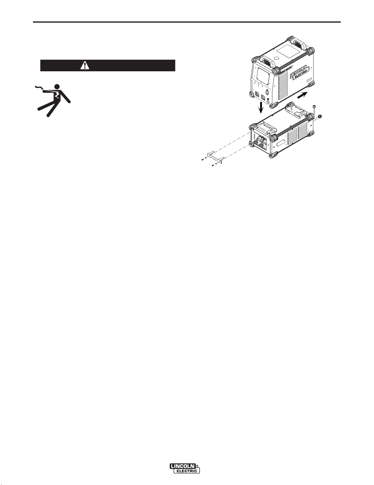
LOCATION AND MOUNTING
(See Figure A.1)
Mount the STT
compatible Power Wave “S” series power source utilizing the quick lock mechanism as shown. The STT
Module will operate in harsh environments and can be
used outdoors. Even so, it is important that simple
preventative measures are followed in order to assure
long life and reliable operation.
• The machine must be located where there is free
circulation of clean air such that movement into
and out of the louvers will not be restricted.
• Dirt and dust that can be drawn into the machine
should be kept to a minimum. The use of air filters
on the air intake is not recommended because normal air flow may be restricted. Failure to observe
these precautions can result in excessive operating temperatures and nuisance shutdown.
• Keep the machine dry. Shelter from rain and snow.
Do not place on wet ground or in puddles.
®
Module directly to the bottom of a
®
FIGURE A.1
CONTROL CABLE CONNECTIONS
®
General Guidelines
Genuine Lincoln control cables should be used at all
times (except where noted otherwise). Lincoln cables
are specifically designed for the communication and
power needs of the Power Wave systems. Most are
designed to be connected end to end for ease of
extension. Generally, it is recommended that the total
length not exceed 100 feet (30.5 m). The use of nonstandard cables, especially in lengths greater than 25
feet, can lead to communication problems (system
shutdowns), poor motor acceleration (poor arc starting), and low wire driving force (wire feeding problems). Always use the shortest length of control cable
possible, and DO NOT coil excess cable.
• Do not mount the Power Wave “S” series power
®
source and STT
Module combination over combustible surfaces. Where there is a combustible
surface directly under stationary or fixed electrical
equipment, that surface shall be covered with a
steel plate at least .060” (1.6mm) thick, which shall
extend not less than 5.90” (150mm) beyond the
equipment on all sides.
POWER WAVE®STT®MODULE
Page 10

A-3
INSTALLATION
A-3
CAUTION
Regarding cable placement, best results will be
obtained when control cables are routed separate from
the weld cables. This minimizes the possibility of interference between the high currents flowing through the
weld cables, and the low level signals in the control
cables. These recommendations apply to all communication cables including ArcLink®connections.
------------------------------------------------------------------------
CONNECTION BETWEEN POWER SOURCE
AND STT®MODULE (ARCLINK®AND
DIFFERENTIAL I/O PIGTAILS)
The pigtail connections on the STT®Module include all signal and power lines required for proper operation. With the
STT®Module securely fastened to the power source, connect the pigtails to their respective receptacles on the back
of the power source per the connection diagrams located in
the “Installation Section”.
Special Instructions:
K2902-1
Some earlier vintage S350 power sources (Code 11589)
may not include a 6-pin Differential I/O receptacle. If the
receptacle is not present on the host power source, contact
the Lincoln Electric Service Department to obtain an
S350/STT Retrofit Kit (S28481).
Never reverse the polarity to the input of the STT
Module (DO NOT connect the negative stud of the
power source to input stud of the STT
This may result in damage to the STT®Module!
------------------------------------------------------------------------
• Negative Electrode Polarity: The STT®process CANNOT
be run using negative electrode polarity. However, for
®
processes other than STT
requiring negative polarity, such
as some Innershield applications, the electrode and work
connections should be reversed at the load, NOT at the
input to the STT
®
Module. Connect the electrode cable to
the negative (-) stud of the power source, and work cable to
the output stud of the STT®Module per the Negative Polarity
Connection Diagram.
(See Figure A.2)
WARNING
®
®
Module).
FIGURE A.2
NEGATIVE POLARITY
CONNECTION
NOT
TO BE USED FOR
(
STT PROCESS)
®
Module to ArcLink®Wire Feeders (K1543 or K2683
STT
ArcLink®Control Cable)
The K2902-1 STT®Module includes an ArcLink®output
receptacle for connection to compatible wire feeders. The
control cable consists of two power leads, one twisted pair
for digital communication, and one lead for voltage sensing.
The 5 pin ArcLink®receptacle is located on the lower rear
portion of the STT®Module. The control cable is keyed and
polarized to prevent improper connection. Best results will
be obtained when control cables are routed separate from
the weld cables, especially in long distance applications.
The recommended combined length of the ArcLink®control
cable network should not exceed 200ft.
ELECTRODE AND WORK CONNECTIONS
Connect the electrode and work cables per the connection
diagrams included in this document. Size and route the
cables per the following:
• Positive Electrode Polarity: Most welding appli-
cations run with the electrode being positive (+).
For those applications, connect the electrode cable
between the wire drive feed plate and the output
stud on the STT®Module. Connect a work lead
from the negative (-) power source output stud to
the work piece per the Connection Diagram.
(See Figure A.5)
TO WORK
TO ELECTRODE
(FEEDER)
TO WORK
TO ELECTRODE
(FEEDER)
CAUTION
-Negative electrode polarity operation may require
reconfiguration of the power source voltage sense
leads. See the Remote Sense Lead section in the
power source instruction manual for further
details.
------------------------------------------------------------------------
For additional Safety information regarding the electrode and work cable set-up, See the standard
“SAFETY INFORMATION” located in the front of the
Instruction Manuals.
POWER WAVE®STT®MODULE
Page 11

A-4
INSTALLATION
TABLE A.1
OUTPUT CABLE GUIDELINES
A-4
Percent
Duty
Amperes
200
200
225
225
250
250
250
250
300
325
350
400
400
500
** Tabled values are for operation at ambient temperatures of 40°C and below. Applications above 40°C may require cables larger than
recommended, or cables rated higher than 75°C.
GENERAL GUIDELINES
• Select the appropriate size cables per the “Output
Cable Guidelines” (See Table A.1. Excessive
voltage drops caused by undersized welding
cables and poor connections often result in unsatisfactory welding performance. Always use the
largest welding cables (electrode and work) that
are practical, and be sure all connections are clean
and tight.
Note: Excessive heat in the weld circuit indicates
undersized cables and/or bad connections.
• Route all cables directly to the work and wire feeder, avoid excessive lengths and do not coil excess
cable. Route the electrode and work cables in
close proximity to one another to minimize the loop
area and therefore the inductance of the weld circuit.
• Always weld in a direction away from the work
(ground) connection.
Cycle
60
100
20
40 & 30
30
40
60
100
60
100
60
60
100
60
CABLE SIZES FOR COMBINED LENGTHS OF ELECTRODE AND WORK CABLES
(RUBBER COVERED COPPER - RATED 75°C)**
0 to 50 Ft. 50 to 100 Ft. 100 to 150 Ft. 150 to 200 Ft. 200 to 250 Ft.
2
2
4 or 5
3
3
2
1
1
1
2/0
1/0
2/0
3/0
2/0
2
2
3
3
3
2
1
1
1
2/0
1/0
2/0
3/0
2/0
2
2
2
2
2
1
1
1
1
2/0
2/0
2/0
3/0
3/0
1
1
1
1
1
1
1
1
1/0
2/0
2/0
3/0
3/0
3/0
1/0
1/0
1/0
1/0
1/0
1/0
1/0
1/0
2/0
3/0
3/0
4/0
4/0
4/0
CABLE INDUCTANCE AND ITS EFFECTS
ON WELDING
Excessive cable inductance will cause the welding
performance to degrade. There are several factors
that contribute to the overall inductance of the cabling
system including cable size, and loop area. The loop
area is defined by the separation distance between
the electrode and work cables, and the overall welding
loop length. The welding loop length is defined as the
total of length of the electrode cable (A) + work cable
(B) + work path (C) (see Figure A.3 below). To minimize inductance always use the appropriate size
cables, and whenever possible, run the electrode and
work cables in close proximity to one another to minimize the loop area. Since the most significant factor in
cable inductance is the welding loop length, avoid
excessive lengths and do not coil excess cable. For
long work piece lengths, a sliding ground should be
considered to keep the total welding loop length as
short as possible.
See Table A.1 for copper cable sizes recommended
for different currents and duty cycles. Lengths stipulated are the distance from the welder to work and back
to the welder again. Cable sizes are increased for
greater lengths primarily for the purpose of minimizing
cable drop.
POWER WAVE®STT®MODULE
POWER
WAVE
FIGURE A.3
A
C
WORK
B
Page 12

A-5
INSTALLATION
REMOTE SENSE LEAD CONNECTIONS
Voltage Sensing Overview
The STT®welding process requires the use of remote
voltage sense leads to more accurately monitor the
conditions of the arc. These leads originate in the
power source, and are connected and configured
external to the STT®Module. Consult the power
source instruction manual for detailed information.
Note:
Other processes run through the STT
necessarily require sense leads, but will benefit from
their use. Consult the power source instruction manual for recommendations.
General Voltage Sensing Considerations for
Multiple Arc Systems
Special care must be taken when more than one arc
is welding simultaneously on a single part. The placement and configuration of remote work voltage sense
leads is critical to the proper operation of multiple arc
STT®applications.
®
Module do not
A-5
• Position the sense leads out of the path of the
weld current. Especially any current paths com-
mon to adjacent arcs. Current from adjacent arcs
can induce voltage into each others current paths
that can be misinterpreted by the power sources,
and result in arc interference.
• For longitudinal applications, connect all work
leads at one end of the weldment, and all of the
work voltage sense leads at the opposite end of
the weldment. Perform welding in the direction
away from the work leads and toward the sense
leads. (See Figure A.4)
RECOMMENDATIONS:
DIRECTION
OF TRAVEL
FIGURE A.4
CONNECT ALL SENSE
LEADS AT THE END
OF THE WELD.
CONNECT ALL
WORK LEADS AT
THE BEGINNING
OF THE WELD.
POWER WAVE®STT®MODULE
Page 13

A-6
INSTALLATION
A-6
• For circumferential applications, connect all work leads on one side of the weld joint, and all of the work volt-
age sense leads on the opposite side, such that they are out of the current path.
POWER
SOURCE
#1
POWER
SOURCE
#2
POWER
SOURCE
#1
POWER
SOURCE
#2
POWER
SOURCE
#1
POWER
SOURCE
#2
POWER WAVE®STT®MODULE
Page 14

A-7
INSTALLATION
CONNECTION DIAGRAM SYSTEM
STT®MODULE CONNECTION DIAGRAM
FIGURE A.5
K1543-XX
K1543-XX
K940-XX
FROM
FEEDER
A-7
WORK
REFER TO "OUTPUT CABLE
GUIDELINES" FOR
RECOMMENDED CABLE SIZE
ELECTRODE
K2230-1
Power Feed-10M
M22497
WORK
POWER WAVE®STT®MODULE
K1543-XX
TO STT
® MODULE
Page 15

B-1
OPERATION
B-1
SAFETY PRECAUTIONS
Read this entire section of operating instructions
before operating the machine.
WARNING
ELECTRIC SHOCK can kill.
• Disconnect input power before
servicing.
• Do not operate with covers removed.
• Do not touch electrically live parts.
• Only qualified persons should install, use or
service this equipment.
------------------------------------------------------------------------
GENERAL DESCRIPTION
General Physical Description
The POWER WAVE
enabling compatible power sources to perform the STT
function without limiting the normal multi-process rating
of the host machine. It is intended for use with medium
range “S”– series Power Wave
the S350. The module itself is a low profile pedestal,
designed to seamlessly integrate with compatible power
sources and water coolers.
General Functional Description
The POWER WAVE
high speed, high capacity output switch, connected in
series with the positive output of the power source. It
communicates module status and identification information to the power source via the ArcLink®protocol, and
receives a high speed synchronized switching command
via a dedicated digital link.
®
STT®MODULE is an accessory
®
power sources such as
®
STT®MODULE is essentially a
®
POWER-UP SEQUENCE
Note:
The POWER WAVE
®
STT®MODULE is capable of
withstanding a peak output current of 750 amps. The
allowable maximum average output current is time
dependant, and ultimately limited by the host power
source.
COMMON WELDING PROCEDURES
MAKING A WELD
Choose the electrode material, electrode size, shielding
gas, and process (GMAW, GMAW-P, GMAW STT etc.)
appropriate for the material to be welded.
Select the weld mode that best matches the desired
welding process. The standard weld set shipped with the
host power source encompasses a wide range of common processes that will meet most needs. If the STT
modes are not available, or if a special weld mode is
desired, visit www.powerwavesoftware.com or contact
the local Lincoln Electric sales representative.
To make a weld, the power source needs to know the
desired welding parameters. Set the parameters on the
user interface typically located on the wire feeder. The
user interface sends the parameters (arc voltage, wire
TM
feed speed, UltimArc
via the ArcLink®communication protocol through the control cables. The power source controls the POWER
WAVE
®
STT®MODULE based on the selected weld
mode.
For a more detailed description, and specific operating
instructions, consult the power source Instruction
Manual.
value, etc.), to the power source
The POWER WAVE®STT®MODULE will be powered up
at the same time as the power source. The status light
will blink green for about a minute while the system is
configuring. After this time, the status lights will turn a
steady green indicating the machine is ready.
The fan in the POWER WAVE
®
STT®MODULE will run
only when the power source fan is activated.
DUTY CYCLE
The POWER WAVE®STT®MODULE is rated at 450
amps at a 100% duty cycle. It is further rated to support
500 amps at a 60% duty cycle and 550 amps at a 40%
duty cycle. The duty cycle is based on a ten-minute period. A 60% duty cycle represents 6 minutes of welding
and 4 minutes of idling in a ten-minute period.
POWER WAVE®STT®MODULE
RECOMMENDED PROCESSES AND
EQUIPMENT
RECOMMENDED PROCESSES
The POWER WAVE®STT®MODULE is recommended
for all process supported by the host power source
including, but not limited to SMAW, GMAW, GMAW-P,
GMAW-STT.
PROCESS LIMITATIONS
The POWER WAVE®STT®MODULE is unaffected by
the voltage at the load, and therefore processes are only
limited by the current and duty cycle ratings listed in the
specifications for the product. The POWER WAVE
MODULE is designed to protect itself from the excessive
transient voltages associated with highly inductive weld
circuits. These high inductance circuits may result in
unsatisfactory performance, but will not damage the
module.
®
STT
®
Page 16

B-2
OPERATION
B-2
Although the STT Module can be configured to support
negative electrode polarity processes, such as
Innershield, the STT process must be configured to use
positive electrode polarity.
EQUIPMENT LIMITATIONS
The POWER WAVE®STT®MODULE is intended for
use with compatible medium range “S” – series
POWER WAVE
®
power sources such as the S350.
STT®MODULE (CE) CASE FRONT
COMMON EQUIPMENT PACKAGES
BASIC PACKAGE
K2902-1
K2823-1
K2370-2
K1543-xx
STT®Module
®
Power Wave
S350
POWER FEED-10M
ArcLink
®
Cable (5 pin) – connects wire feeder to power
source.
OPTIONAL WIRE FEEDERS
K2536
POWER FEED-25M
1
3
2
CASE FRONT DESCRIPTIONS
1. Status LED – Provides ArcLink®status of Power Wave STT®Module.
Note: During normal power-up, the LED will flash green up to 60 seconds as the equipment performs self tests.
LED condition
Steady green.
Blinking green.
Alternating green
and red
.
Definition
System okay. The power source and wire feeder are communicating normally.
Occurs during a reset and indicates the power source is identifying each component in the
system. This is normal for the first 60 seconds after power-up, or if the system configuration
is changed during operation.
Non-recoverable system fault. If the power source or wire feeder status LED is flashing any
combination of red and green, errors are present in the system. Read the error code before
the machine is turned off.
2. STT INPUT – Connects directly to the Positive output of the power source.
3. STT OUTPUT – Connects directly to the wire feeder, torch or electrode.
POWER WAVE®STT®MODULE
Page 17

B-3
OPERATION
B-3
STT®MODULE CASE BACK
2
1
3
4
CASE BACK DESCRIPTIONS
1. ArcLink®Pigtail – Connects directly to the ArcLink®Out receptacle on the rear of the power source.
2. Differential I/O Pigtail – Connects directly to the Differential I/O output receptacle on the rear of the power
source.
3. Differential I/O (Sync Tandem) Output – Supports Synchronized Tandem MIG Welding with other compatible
power sources. Note: This feature is not compatible with the STT
using STT®weld modes.
4. ArcLink®(Out) – Available on the standard model only. Provides an ArcLink®pass through connection for all
compatible ArcLink®wire feeders.
®
process, and is therefore disabled when
POWER WAVE®STT®MODULE
Page 18

D-1
MAINTENANCE
SAFETY PRECAUTIONS
WARNING
ELECTRIC SHOCK can kill.
• Disconnect input power before
servicing.
• Do not operate with covers removed.
• Do not touch electrically live parts.
• Only qualified persons should install,
use or service this equipment.
------------------------------------------------------------------------
See additional warning information
throughout this operator’s manual and
the Engine manual as well.
-----------------------------------------------------------
ROUTINE MAINTENANCE
Routine maintenance consists of periodically blowing
out the machine, using a low-pressure air stream, to
remove accumulated dust and dirt from the intake and
outlet louvers, and the cooling channels in the
machine. Also verify the STT
tional when the power source fan is activated.
®
Module fan is opera-
D-1
CALIBRATION SPECIFICATION
Due to the nature of its operation, calibration of the
®
STT
Module is not required. From a system perspective, the output calibration of the power source and
wire feeder should be performed as directed in their
respective instruction manuals.
When calibrating the power source voltage using the
Weld Manager utility, the actual output voltage should
be monitored directly at the output of the power
source (not the STT
necessary because the default calibration mode
senses voltage directly from the power source output
studs. The STT
current calibration.
®
®
Module output). This is
Module has no effect on the output
POWER WAVE®STT®MODULE
Page 19

E-1
TROUBLESHOOTING
HOW TO USE TROUBLESHOOTING GUIDE
WARNING
Service and Repair should only be performed by Lincoln Electric Factory Trained Personnel.
Unauthorized repairs performed on this equipment may result in danger to the technician and
machine operator and will invalidate your factory warranty. For your safety and to avoid Electrical
Shock, please observe all safety notes and precautions detailed throughout this manual.
__________________________________________________________________________
E-1
This Troubleshooting Guide is provided to help you
locate and repair possible machine malfunctions.
Simply follow the three-step procedure listed below.
Step 1. LOCATE PROBLEM (SYMPTOM).
Look under the column labeled “PROBLEM (SYMPTOMS)”. This column describes possible symptoms
that the machine may exhibit. Find the listing that
best describes the symptom that the machine is
exhibiting.
Step 2. POSSIBLE CAUSE.
The second column labeled “POSSIBLE CAUSE” lists
the obvious external possibilities that may contribute
to the machine symptom.
Step 3. RECOMMENDED COURSE OF ACTION
This column provides a course of action for the
Possible Cause, generally it states to contact your
local Lincoln Authorized Field Service Facility.
If you do not understand or are unable to perform the
Recommended Course of Action safely, contact your
local Lincoln Authorized Field Service Facility.
CAUTION
If for any reason you do not understand the test procedures or are unable to perform the tests/repairs safely, contact your
Local Lincoln Authorized Field Service Facility for technical troubleshooting assistance before you proceed.
POWER WAVE®STT®MODULE
Page 20

E-2
PREPARATION
• Connect the STT®module to a Power Wave S350 or other compatible machine.
(This test assumes the host power source has been calibrated.)
• Verify the latest software is loaded in the Power Wave.
TROUBLESHOOTING
Observe all Safety Guidelines detailed throughout this manual
STT®MODULE FUNCTIONAL TEST
E-2
• Short the Work (-) to the Electrode (STT
(Total Cable Length ≤ 10ft.)
K1543-XX
TEST PROCEDURE
• Enable test modes on the UI of the Wire Feeder.
See Wire Feeder instruction manual (set-up menu selection P.99).
• Select test mode 208 (STT®Test Mode).
If mode 208 is not available with the test modes enabled, the Power Source software must be updated.
• Enable the output.
Pulling the trigger, or turn the trim knob clockwise.
STT OUTPUT TO
NEGATIVE STUD
®
Output).
STT INPUT TO
POSITIVE STUD
K1543-XX
TO STT MODULE
• Read Voltage feedback displayed on the Wire Feeder Display.
Voltage
Indication / Possible Cause
STT®Switch Shorted:
• Faulty or disconnected Differential I/O control signal (grey cable located at rear of module).
Verify cable connections (including those internal to the STT®Switch and host power source).
< 2V
• STT®Input tied to negative weld output (Reverse Polarity, typically accompanied by Error 99).
Verify STT®Switch is properly connected.
• STT®Switch Shorted (typically accompanied by Error 99).
Disconnect and perform STT®Switch PCB Test.
5 - 10V
Normal Operation
STT®Switch Open:
• Loose or open connection.
Verify weld cable connections (both internal and external to the module – including quick
> 40V
connections).
• STT®Switch not closing (may be accompanied by Error 99).
Verify status of the STT®Switch board via the “on board” diagnostic LEDʼs.
CAUTION
If for any reason you do not understand the test procedures or are unable to perform the tests/repairs safely, contact your
Local Lincoln Authorized Field Service Facility for technical troubleshooting assistance before you proceed.
POWER WAVE®STT®MODULE
Page 21

E-3
TROUBLESHOOTING
Observe all Safety Guidelines detailed throughout this manual
USING THE STATUS LED TO TROUBLESHOOT SYSTEM PROBLEMS
The STT®Module is equipped with a Status Light. If a problem occurs it is important to note the
condition of the status lights. Therefore, prior to cycling power to the system, check the
power source status light for error sequences in Table E.1.
TABLE E.1
Light
Condition
Meaning
E-3
Steady Green
Blinking Green
Fast Blinking Green
Alternating Green and Red
System OK. Power source is operational, and is communicating normally with all healthy
peripheral equipment connected to its ArcLink®network.
Occurs during power up or a system reset, and indicates the power source is
mapping (identifying) each component in the system. Normal for first 1-30 seconds after power is turned on, or if the system configuration is changed during
operation.
Under normal conditions indicates Auto-mapping has failed.
Also used by the diagnostic utility (included in the Weld Manager
available at www.powerwavesoftware.com) to identify the selected machine
when connecting to a specific IP address.
Non-recoverable system fault. If the Status lights are flashing any combination
of red and green, errors are present. Read the error code(s) before the
machine is turned off.
Error Code interpretation through the Status light is detailed in the Service
Manual. Individual code digits are flashed in red with a long pause between
digits. If more than one code is present, the codes will be separated by a
green light. Only active error conditions will be accessible through the Status
Light.
Error codes can also be retrieved with the diagnostics utility (included in the
Weld Manager®Utilities available at www.powerwavesoftware.com). This is
the preferred method, since it can access historical information contained in
the error log. To clear the active error(s), turn power source off, and back on
to reset.
®
Utilities
Steady Red
Blinking Red
Not applicable.
Not applicable.
CAUTION
If for any reason you do not understand the test procedures or are unable to perform the tests/repairs safely, contact your
Local Lincoln Authorized Field Service Facility for technical troubleshooting assistance before you proceed.
POWER WAVE®STT®MODULE
Page 22

E-4
The following is a partial list of possible error codes for the STT®MODULE.
Error Code #
TROUBLESHOOTING
Observe all Safety Guidelines detailed throughout this manual
ERROR CODES FOR THE STT®MODULE
STT®MODULE
Indication
E-4
36 Thermal error
39 Misc. hardware fault
99 STT Status error
Other
Indicates over temperature. Usually accompanied by Thermal LED.
Check fan operation. Be sure process does not exceed duty cycle limit
of the machine.
Unknown glitch has occurred on the fault interrupt circuitry. Sometimes
caused by primary over current fault, or intermittent connections in the
thermostat circuit.
®
Error reported by the STT
Generally caused by misconnection of welding leads (reverse polarity).
May also be caused by loss of input voltage or board failure. Observe
diagnostic LEDʼs on the STT
cause.
A complete list of error codes is available in the Power Wave Manager
Utility (available at www.powerwavesoftware.com).
Error codes that contain three or four digits are defined as fatal errors.
These codes generally indicate internal errors on the STT
Status PC Board. If cycling the input power on the machine does not
clear the error, contact the Service Department.
Switch PC Board.
®
Switch PC Board to determine the exact
®
Module
CAUTION
If for any reason you do not understand the test procedures or are unable to perform the tests/repairs safely, contact your
Local Lincoln Authorized Field Service Facility for technical troubleshooting assistance before you proceed.
POWER WAVE®STT®MODULE
Page 23

E-5
MACHINE
OUTPUT
LED1
(GATE)
TROUBLESHOOTING
Observe all Safety Guidelines detailed throughout this manual
ON BOARD LEDʼS FOR THE STT®SWITCH PC BOARD
STT®SWITCH PC BOARD
LED2
(STATUS)
LED3
(+15V)
INDICATION
E-5
ON/OFF
ON
ON
ON/OFF
DIFFERENTIAL I/
(STT SWITCH SIGNAL)
ON
OFF
ON
ON
ON
ON
Normal Condition – STT®Switch is ON.
Normal Condition – STT
Note: During normal STT
®
Switch has been commanded OFF.
®
operation the OFF state of the LED
may only be detectable as a slight dimming.
OFF
OFF
ON
Status Failure (only when triggered). Should be accompanied by
Error 99 on the external STT
®
Module Status LED. Most likely
caused by weld cable misconnection (reverse polarity).
OFF
OFF
ON/OFF
Status Failure (constantly). Should be accompanied by Error 99
on the external STT®Module Status LED. Most likely caused by
the on board power supply under-voltage lockout. Verify input voltage to the STT®Switch board.
O
STT SWITCH
G6768-1
J3
B1
B
2
B3 B
B9
SNUBBER
4
STT IN
(B1 - B4)
STT STATU S
(OUTPUT)
LED2
LED1
C2
C1
B5 B6 B7 B8
2
J
LED3
STT O UT
(B5 - B 8)
J1
INPUT POWER
(40 VDC)
CAUTION
If for any reason you do not understand the test procedures or are unable to perform the tests/repairs safely, contact your
Local Lincoln Authorized Field Service Facility for technical troubleshooting assistance before you proceed.
POWER WAVE®STT®MODULE
Page 24

E-6
PROBLEMS
(SYMPTOMS)
Input fuses keep blowing
TROUBLESHOOTING
Observe all Safety Guidelines detailed throughout this manual
POSSIBLE
CAUSE
BASIC MACHINE PROBLEMS
1. Improperly sized input fuses.
2. Improper Weld Procedure requiring output levels in excess of
machine rating.
3. Major physical or electrical damage is evident in the power source
when the sheet metal covers are
removed.
1. Make sure fuses are properly
2. Reduce output current, duty cycle,
3. Contact your local authorized
RECOMMENDED
COURSE OF ACTION
sized. See installation section of
this manual for recommended
sizes.
or both.
Lincoln Electric Field Service
facility for technical assistance.
E-6
Machine will not power up (no lights
on power source, STT
®
Module or
Wire Feeder).
No Status Light on STT®Module
Machine won’t weld, when attached
®
to STT
Module.
1. No Input Power.
1. 40VDC input not present at STT
Module.
2. Malfunctioning Status LED.
®
1. STT
2. STT
Status Error.
®
Thermal Error.
3. 40VDC input not present at STT
Module.
4. Internal open circuit
1. Make sure input supply disconnect has been turned ON. Check
input fuses. Make certain that the
Power Switch on the power
source is in the “ON” position.
®
1 Check ArcLink®cable. Verify
40VDC per wiring diagram.
• If wire feeder is functional and
connected through the STT
Module, suspect connection
issue in STT®Module. Verify
condition of LED’s on STT
Switch PCB (viewable through
rear and left side louvers.
2. Verify status LED is properly
installed and has not disengaged
from the lens.
1. Make certain the polarity of the
STT®Module is correct per the
connection diagram (Positive to
STT Input).
• If polarity is correct, verify condi-
tion of LED’s on STT®Switch
PCB (viewable through rear and
left side louvers.
2. See “Thermal error indiction...”
section.
®
3. See “No Status Light on STT®…”
section.
4. Check for loose or broken connection in STT®Module weld circuit.
®
®
CAUTION
If for any reason you do not understand the test procedures or are unable to perform the tests/repairs safely, contact your
Local Lincoln Authorized Field Service Facility for technical troubleshooting assistance before you proceed.
POWER WAVE®STT®MODULE
Page 25

E-7
Observe all Safety Guidelines detailed throughout this manual
PROBLEMS
(SYMPTOMS)
Thermal error indication on STT
Module (error 36).
WELD AND ARC QUALITY PROBLEMS
TROUBLESHOOTING
POSSIBLE CAUSE RECOMMENDED
BASIC MACHINE PROBLEMS
®
1. Improper fan operation.
2. STT®Switch PC board thermostat.
3. Open thermostat circuit.
E-7
COURSE OF ACTION
1. Check for proper fan operation.
(Fans typically run whenever output power is on.) Check for material blocking intake or exhaust louvers, or for excessive dirt clogging
cooling channels in machine.
2. After machine has cooled, reduce
load, duty cycle, or both. Check
for material blocking intake or
exhaust louvers and heat sink
fins.
3. Check for broken wires, open connections or faulty thermostat in the
®
Module.
STT
General degradation of weld performance.
1. Wire feed problem.
2. Cabling problems.
3. Loss of, or improper Shielding
Gas.
4. Verify weld mode is correct for
process.
5. Machine calibration.
®
6. STT
Process ONLY: Excessive
cable inductance or STT®snubber
malfunction.
1. Check for feeding problems.
Check actual WFS vs. preset.
Verify proper wire drive and gear
ratio has been selected.
2. Check for bad connections,
excessive loops in cable, etc.
NOTE: The presence of heat in
the external welding circuit indicates poor connections or undersized cables.
3. Verify gas flow and type are correct.
4. Select the correct weld mode for
the application.
5. Verify the calibration of the power
source output current and voltage.
6. Excessive cable inductance or
®
snubber malfunction can
STT
cause the transient voltage to
exceed the safe operating thresh-
®
old on the STT
Switch PC board.
Under these conditions the STT
switch turns ON to protect itself.
Follow recommended cable guidelines to minimize the inductance,
and inspect the snubber resistor
circuit for damage.
®
CAUTION
If for any reason you do not understand the test procedures or are unable to perform the tests/repairs safely, contact your
Local Lincoln Authorized Field Service Facility for technical troubleshooting assistance before you proceed.
POWER WAVE®STT®MODULE
Page 26

F-1
Enhanced Diagram
DIAGRAMS
F-1
POWER WAVE®STT®MODULE
NOTE: This diagram is for reference only. It may not be accurate for all machines covered by this manual. The specific diagram for a particular code is pasted inside the
machine on one of the enclosure panels. If the diagram is illegible, write to the Service Department for a replacement. Give the equipment code number.
Page 27

F-2
11.51
10.49
DIMENSION PRINT
F-2
8.48
3.97
6.00
3.97
24.80
25.42
2.48 18.35 3.98
13.94
A.01
L15814-2
POWER WAVE®STT®MODULE
Page 28

WARNING
Spanish
AVISO DE
PRECAUCION
• Do not touch electrically live parts or
electrode with skin or wet clothing.
• Insulate yourself from work and
ground.
• No toque las partes o los electrodos
bajo carga con la piel o ropa mojada.
• Aislese del trabajo y de la tierra.
• Keep flammable materials away.
• Mantenga el material combustible
fuera del área de trabajo.
• Wear eye, ear and body protection.
• Protéjase los ojos, los oídos y el
cuerpo.
French
ATTENTION
German
WARNUNG
Portuguese
ATENÇÃO
Japanese
Chinese
Korean
Arabic
• Ne laissez ni la peau ni des vête-
ments mouillés entrer en contact
avec des pièces sous tension.
• Isolez-vous du travail et de la terre.
• Berühren Sie keine stromführenden
Teile oder Elektroden mit Ihrem
Körper oder feuchter Kleidung!
• Isolieren Sie sich von den
Elektroden und dem Erdboden!
• Não toque partes elétricas e electro-
dos com a pele ou roupa molhada.
• Isole-se da peça e terra.
• Gardez à l’écart de tout matériel
• Entfernen Sie brennbarres Material!
• Mantenha inflamáveis bem guarda-
inflammable.
dos.
• Protégez vos yeux, vos oreilles et
votre corps.
• Tragen Sie Augen-, Ohren- und Kör-
perschutz!
• Use proteção para a vista, ouvido e
corpo.
READ AND UNDERSTAND THE MANUFACTURER’S INSTRUCTION FOR THIS EQUIPMENT AND THE
CONSUMABLES TO BE USED AND FOLLOW YOUR EMPLOYER’S SAFETY PRACTICES.
SE RECOMIENDA LEER Y ENTENDER LAS INSTRUCCIONES DEL FABRICANTE PARA EL USO DE
ESTE EQUIPO Y LOS CONSUMIBLES QUE VA A UTILIZAR, SIGA LAS MEDIDAS DE SEGURIDAD DE SU
SUPERVISOR.
LISEZ ET COMPRENEZ LES INSTRUCTIONS DU FABRICANT EN CE QUI REGARDE CET EQUIPMENT
ET LES PRODUITS A ETRE EMPLOYES ET SUIVEZ LES PROCEDURES DE SECURITE DE VOTRE
EMPLOYEUR.
LESEN SIE UND BEFOLGEN SIE DIE BETRIEBSANLEITUNG DER ANLAGE UND DEN ELEKTRODENEINSATZ DES HERSTELLERS. DIE UNFALLVERHÜTUNGSVORSCHRIFTEN DES ARBEITGEBERS
SIND EBENFALLS ZU BEACHTEN.
Page 29

• Keep your head out of fumes.
• Use ventilation or exhaust to
remove fumes from breathing zone.
• Turn power off before servicing.
• Do not operate with panel open or
guards off.
WARNING
• Los humos fuera de la zona de res-
piración.
• Mantenga la cabeza fuera de los
humos. Utilice ventilación o
aspiración para gases.
• Gardez la tête à l’écart des fumées.
• Utilisez un ventilateur ou un aspira-
teur pour ôter les fumées des zones
de travail.
• Vermeiden Sie das Einatmen von
Schweibrauch!
• Sorgen Sie für gute Be- und
Entlüftung des Arbeitsplatzes!
• Mantenha seu rosto da fumaça.
• Use ventilação e exhaustão para
remover fumo da zona respiratória.
• Desconectar el cable de ali-
mentación de poder de la máquina
antes de iniciar cualquier servicio.
• Débranchez le courant avant l’entre-
tien.
• Strom vor Wartungsarbeiten
abschalten! (Netzstrom völlig öffnen;
Maschine anhalten!)
•
Não opere com as tampas removidas.
•
Desligue a corrente antes de fazer
serviço.
•
Não toque as partes elétricas nuas.
• No operar con panel abierto o
• N’opérez pas avec les panneaux
• Anlage nie ohne Schutzgehäuse
• Mantenha-se afastado das partes
• Não opere com os paineis abertos
guardas quitadas.
ouverts ou avec les dispositifs de
protection enlevés.
oder Innenschutzverkleidung in
Betrieb setzen!
moventes.
ou guardas removidas.
Spanish
AVISO DE
PRECAUCION
French
ATTENTION
German
WARNUNG
Portuguese
ATENÇÃO
Japanese
Chinese
Korean
Arabic
LEIA E COMPREENDA AS INSTRUÇÕES DO FABRICANTE PARA ESTE EQUIPAMENTO E AS PARTES
DE USO, E SIGA AS PRÁTICAS DE SEGURANÇA DO EMPREGADOR.
Page 30

• World's Leader in Welding and Cutting Products •
• Sales and Service through Subsidiaries and Distributors Worldwide •
Cleveland, Ohio 44117-1199 U.S.A. TEL: 216.481.8100 FAX: 216.486.1751 WEB SITE: www.lincolnelectric.com
 Loading...