

Page 1

IM10023
RETURN TO MAIN MENU
MMAAXXssaa™1100 CCOONNTTRROOLLLLEERR
For use with machines having Code Numbers:
Safety Depends on You
Lincoln arc welding and cutting
equipment is designed and built
with saf ety in mind. How ever,
your overall safety can be
increased by proper installation
... and thoughtful operation on
your par t. DO NOT INSTALL,
OPERATE OR REPAIR THIS
EQUIPMENT WITHOUT READING THIS MANUAL AND THE
SAFETY PRECAUTIONS CONTAINED THROUGHOUT. And,
most importantly, think bef ore
you act and be careful.
February, 2010
11590
Cleveland, Ohio 44117-1199 U.S.A. TEL: 216.481.8100 FAX: 216.486.1751 WEB SITE: www.lincolnelectric.com
IP 23
OPERATOR’S MANUAL
Copyright © Lincoln Global Inc.
• World's Leader in Welding and Cutting Products •
• Sales and Service through Subsidiaries and Distributors Worldwide •
Page 2

i
SAFETY
WARNING
CALIFORNIA PROPOSITION 65 WARNINGS
Diesel engine exhaust and some of its constituents
are known to the State of California to cause cancer, birth defects, and other reproductive harm.
The Above For Diesel Engines
ARC WELDING CAN BE HAZARDOUS. PROTECT YOURSELF AND OTHERS FROM POSSIBLE SERIOUS INJURY OR DEATH.
KEEP CHILDREN AWAY. PACEMAKER WEARERS SHOULD CONSULT WITH THEIR DOCTOR BEFORE OPERATING.
Read and understand the following safety highlights. For additional safety information, it is strongly recommended that you
purchase a copy of “Safety in Welding & Cutting - ANSI Standard Z49.1” from the American Welding Society, P.O. Box
351040, Miami, Florida 33135 or CSA Standard W117.2-1974. A Free copy of “Arc Welding Safety” booklet E205 is available
from the Lincoln Electric Company, 22801 St. Clair Avenue, Cleveland, Ohio 44117-1199.
BE SURE THAT ALL INSTALLATION, OPERATION, MAINTENANCE AND REPAIR PROCEDURES ARE
PERFORMED ONLY BY QUALIFIED INDIVIDUALS.
The engine exhaust from this product contains
chemicals known to the State of California to cause
cancer, birth defects, or other reproductive harm.
The Above For Gasoline Engines
i
FOR ENGINE
powered equipment.
1.a. Turn the engine off before troubleshooting and maintenance
work unless the maintenance work requires it to be running.
____________________________________________________
1.b. Operate engines in open, well-ventilated
areas or vent the engine exhaust fumes
outdoors.
____________________________________________________
1.c. Do not add the fue l near an open f lame
welding arc or when the engine is running.
Stop the engine and allow it to cool before
refueling to prevent spilled fuel from vaporizing on contact with hot engine parts and
igniting. Do not spill fuel when filling tank. If
fuel is spilled, wipe it up and do not start
engine until fumes have been eliminated.
____________________________________________________
1.d. Keep all equipment safety guards, covers and devices in
position and in good repair.Keep hands, hair, clothing and
tools away from V-belts, gears, fans and all other moving
parts when starting, operating or repairing equipment.
____________________________________________________
1.e. In s ome cas es it may be neces sary to rem ove s afety
gu a r d s to perf o r m r equir e d m ainten a n c e. Rem o v e
guards only when necessary and replace them when the
ma i n t e nance re q uirin g th eir re m o v a l is c o m p lete.
Always use the greatest care when working near moving
parts.
___________________________________________________
1.f. Do not put your hands near the engine fan.
Do not attempt to override the governor or
idler by pushing on the throttle control rods
while the engine is running.
1.h. To avoid scalding, do not remove the
radiator pressure cap when the engine is
hot.
ELECTRIC AND
MAGNETIC FIELDS
may be dangerous
2.a. Electric current flowing through a ny c onductor cause s
localized Electric and Magnetic Fields (EMF). Welding
current creates EMF fields around welding cables and
welding machines
2.b. EMF field s may int erfer e with some pacemak ers, and
welders having a pacemaker should consult their physician
before welding.
2.c. Exposure to EMF fields in welding may have other health
effects which are now not known.
2.d. All welders should use the following procedures in order to
minimize exposure to EMF fields from the welding circuit:
2.d.1.
Route the electrode and work cables together - Secure
them with tape when possible.
2.d.2. Nev er coil the e lectrod e lead around your body.
2.d.3. Do not place your body between the electrode and
work cables. If the electrode cable is on your right
side, the work cable should also be on your right side.
___________________________________________________
1.g. To prevent accidentally starting gasoline engines while
turning the engine or welding generator during maintenance
work, disconnect the spark plug wires, distributor cap or
magneto wire as appropriate.
2.d.4. Connect the work cable to the workpiece as close as
possible to the area being welded.
2.d.5. Do not work next to welding power source.
Mar ‘95
Page 3

ii
SAFETY
ii
ELECTRIC SHOCK can
kill.
3.a. The electrode and work (or ground) circuits
are electrically “hot” when the welder is on.
Do not touch these “hot” parts with your bare
skin or wet cloth in g. W ea r dr y, hole-free
gloves to insulate hands.
3.b. Insulate yourself from work and ground using dry insulation.
Make certain the insulation is large enough to cover your full
area of physical contact with work and ground.
In addition to the normal safety precautions, if welding
mu s t be p e rformed under elec t rically hazar d ous
conditions (in damp locations or while wearing wet
clothing; on metal structures such as floors, gratings or
scaffolds; when in cramped positions such as sitting,
kneeling or lying, if there is a high risk of unavoidable or
accidental contact with the workpiece or ground) use
the following equipment:
• Semiautomatic DC Constant Voltage (Wire) Welder.
• DC Manual (Stick) Welder.
• AC Welder with Reduced Voltage Control.
3.c. In semiautomatic or automatic wire welding, the electrode,
electrode reel, welding head, nozzle or sem ia ut om at ic
welding gun are also electrically “hot”.
3.d. Always be sure the work cable makes a good electrical
connection with the metal being welded. The connection
should be as close as possible to the area being welded.
3.e. Ground the work or metal to be welded to a good electrical
(earth) ground.
3.f.
Maintain the electrode holder, work clamp, welding cable and
welding machine in good, safe operating condition. Replace
damaged insulation.
3.g. Never dip the electrode in water for cooling.
3.h. Ne ver s imu ltane ous ly touch ele ctr ica lly “ hot ” par ts of
electrode holders connected to two welders because voltage
between the two can be the total of the open circuit voltage
of both welders.
3.i. When working above floor level, use a safety belt to protect
yourself from a fall should you get a shock.
3.j. Also see Items 6.c. and 8.
ARC RAYS can burn.
4.a. Use a shield with the proper filter and cover
plates to protect your eyes from sparks and
the rays of the arc when welding or observing
open arc welding. Headshield and filter lens
should conform to ANSI Z87. I standards.
4.b. Use suitable clothing made from durable flame-resistant
material to protect your skin and that of your helpers from
the arc rays.
4.c. Protect other nearby personnel with suitable, non-flammable
screening and/or warn them not to watch the arc nor expose
themselves to the arc rays or to hot spatter or metal.
FUMES AND GASES
can be dangerous.
5.a. Welding may produce fumes and gases
hazardous to health. Avoid breathing these
fumes and gases. When welding , keep
your head out of the fume. Use enough
ventilation and/or exhaust at the arc to keep
fumes and gases away from the breathing zone. When
we l ding with e lectrod e s wh i ch r e quire special
ve n tilati on s uch as s tainles s or hard facing (se e
instru ctio ns on container or MSDS ) o r o n l ead or
cadmium plated steel and other metals or coatings
which produce highly toxic fumes, keep exposure as
low as possible and within applicable OSHA PEL and
ACGIH TLV limits using local exhaust or mechanical
ventilation. In confined spaces or in some circumst a nces, outd oors, a r espira tor may be r equired .
Additional precautions are also required when welding
on galvanized steel.
5. b. The operation of welding fume control equipment is affected
by various factors including proper use and positioning of
the equipment, maintenance of the equipment and the specific welding procedure and application involved. Worker
exposure level should be checked upon installation and
periodically thereafter to be certain it is within applicable
OSHA PEL and ACGIH TLV limits.
5.c.
Do not weld in locations near chlorinated hydrocarbon
coming from degreasing, cleaning or spraying operations.
The heat and rays of the arc can react with solvent vapors
form phosgene, a highly toxic gas, and other irritating products.
5.d. Shielding gases used for arc welding can displace air and
caus e injur y or dea th. Alw ays use e nough v entilat ion,
especially in confined areas, to insure breathing air is safe.
vapors
to
5.e. Read and understand the manufacturer’s instructions for this
equipment and the consumables to be used, including the
ma t e r i al s a f e ty d a t a shee t (MSDS) an d fo llow yo u r
employer’s safety practices. MSDS forms are available from
yo u r weld i n g di s t r ibuto r or fr om th e ma n u f actur e r .
5.f. Also see item 1.b.
Jan ‘09
Page 4

iii
SAFETY
iii
WELDING and CUTTING
SPARKS can
cause fire or explosion.
6.a.
Remove fire hazards from the welding area.
If this is not possible, cover them to prevent
Re m e m b er t h a t we l d i n g s p a r ks a n d hot
materials from welding can easily go through small cracks
an d o pen i ngs to adja cen t a r eas . A voi d w eldi ng nea r
hydraulic lines. Have a fire extinguisher readily available.
6.b. Where compressed gases are to be used at the job site,
special precautions should be used to prevent hazardous
situations. Refer to “Safety in Welding and Cutting” (ANSI
Standard Z49.1) and the operating information for the
equipment being used.
6.c. When not welding, make certain no part of the electrode
circuit is touching the work or ground. Accidental contact
can cause overheating and create a fire hazard.
6.d. Do not heat, cut or weld tanks, drums or containers until the
proper steps have been taken to insure that such procedures
will not cause flammable or toxic vapors from substances
inside. They can cause an explosion even
been “cleaned”. For information, purchase “Recommended
Safe Practices for the
Co n t a i ners and Piping That Have Held Haza r d o u s
Substances”, AWS F4.1 from the American Welding Society
(see address above).
6.e. Vent hollow castings or containers before heating, cutting or
welding. They may explode.
Sparks and spatter are thrown from the welding arc. Wear oil
6.f.
free protective garments such as leather gloves, heavy shirt,
cuffless trousers, high shoes and a cap over your hair. Wear
ear plugs when welding out of position or in confined places.
Always wear safety glasses with side shields when in a
welding area.
6.g. Connect the work cable to the work as close to the welding
area as practical. Work cables connected to the building
framework or other locations away from the welding area
increase the possibility of t he w el di ng current passing
through lifting chains, crane cables or other alternate circuits. This can create fire hazards or overheat lifting chains
or cables until they fail.
6.h. Also see item 1.c.
the welding s pa rks fro m startin g a fire.
though
they have
Preparation
for Welding and Cutting of
CYLINDER may explode
if damaged.
7.a. Us e o n ly com p r e ssed g a s c ylind e r s
containing the correct shielding gas for the
pr o c e s s used a n d p r operl y o p e ratin g
re g u l a tors d e signe d f or t h e gas a n d
pressure used. All hoses, fittings, etc. should be suitable for
the application and maintained in good condition.
7.b. Alwa ys keep cyl inder s in an upr ight posit ion sec urely
chained to an undercarriage or fixed support.
7.c. Cylinders should be located:
• Away from areas where they may be struck or subjected to
physical damage.
• A safe distance from arc welding or cutting operations and
any other source of heat, sparks, or flame.
7.d. Never allow the electrode, electrode holder or any other
electrically “hot” parts to touch a cylinder.
7.e. Keep your head and face away from the cylinder valve outlet
when opening the cylinder valve.
7.f. Valve protection caps should always be in place and hand
tight except when the cylinder is in use or connected for
use.
7.g. Re ad and f oll ow the inst ruc tio ns on com pre sse d g as
cylinders, associated equipment, and CGA publication P-l,
“Precautions for Safe Handling of Compressed Gases in
Cylinders,” available from the Compressed Gas Association
1235 Jefferson Davis Highway, Arlington, VA 22202.
FOR ELECTRICALLY
powered equipment.
8.a. Turn off input power using the disconnect
switch at the fuse box before working on
the equipment.
8.b. Install equipment in accord ance with the U.S. National
Electrical Code, all local code s and the manufacturer’s
recommendations.
8.c. Ground the equipment in accordance with the U.S. National
Electrical Code and the manufacturer’s recommendations.
6.I. Read and follow NFPA 51B “ Standard for Fire Prevention
During Welding, Cutting and Other Hot Work”, available
from NFPA, 1 Batterymarch Park, PO box 9101, Quincy, Ma
022690-9101.
6.j. Do not use a welding power source for pipe thawing.
Refer to http://www.lincolnelectric.com/safety for additional safety information.
Jan ‘09
Page 5

iv
SAFETY
iv
PRÉCAUTIONS DE SÛRETÉ
Pour votre propre protection lire et observer toutes les instructions
et les précautions de sûreté specifiques qui parraissent dans ce
manuel aussi bien que les précautions de sûreté générales suivantes:
Sûreté Pour Soudage A L’Arc
1. Protegez-vous contre la secousse électrique:
a. Les circuits à l’électrode et à la piéce sont sous tension
quand la machine à souder est en marche. Eviter toujours
tout contact entre les parties sous tension et la peau nue
ou les vétements mouillés. Porter des gants secs et sans
trous pour isoler les mains.
b. Faire trés attention de bien s’isoler de la masse quand on
soude dans des endroits humides, ou sur un plancher
metallique ou des grilles metalliques, principalement dans
les positions assis ou couché pour lesquelles une grande
partie du corps peut être en contact avec la masse.
c. Maintenir le porte-électrode, la pince de masse, le câble
de soudage et la machine à souder en bon et sûr état
defonctionnement.
d.Ne jamais plonger le porte-électrode dans l’eau pour le
refroidir.
e. Ne jamais toucher simultanément les parties sous tension
des porte-électrodes connectés à deux machines à souder
parce que la tension entre les deux pinces peut être le
total de la tension à vide des deux machines.
f. Si on utilise la machine à souder comme une source de
courant pour soudage semi-automatique, ces precautions
pour le porte-électrode s’applicuent aussi au pistolet de
soudage.
2. Dans le cas de travail au dessus du niveau du sol, se protéger
contre les chutes dans le cas ou on recoit un choc. Ne jamais
enrouler le câble-électrode autour de n’importe quelle partie
du corps.
5. Toujours porter des lunettes de sécurité dans la zone de
soudage. Utiliser des lunettes avec écrans lateraux dans les
zones où l’on pique le laitier.
6. Eloigner les matériaux inflammables ou les recouvrir afin de
prévenir tout risque d’incendie dû aux étincelles.
7. Quand on ne soude pas, poser la pince à une endroit isolé de
la masse. U n cour t- ci rcuit accidental peut provoquer un
échauffement et un risque d’incendie.
8. S’assurer que la masse est connectée le plus prés possible
de la zone de travail qu’il est pratique de le faire. Si on place
la masse sur la charpente de la construction ou d’autres
endroits éloignés de la zone de travail, on augmente le risque
de voir passer le courant de soudage par les chaines de levage, câbles de grue, ou autres circuits. Cela peut provoquer
des risques d’incendie ou d’echauffement des chaines et des
câbles jusqu’à ce qu’ils se rompent.
9. Assurer une ventilation suffisante dans la zone de soudage.
Ceci est particuliérement important pour le soudage de tôles
galvanisées plombées, ou cadmiées ou tout autre métal qui
produit des fumeés toxiques.
10. Ne pas souder en présence de vapeurs de chlore provenant
d’o pérations de d égraissage, nettoyage ou pist olage. La
chaleur ou les rayons de l’arc peuvent réagir avec les vapeurs
du solvant pour produire du phosgéne (gas fortement toxique)
ou autres produits irritants.
11. Pour obtenir de plus amples renseignements sur la sûreté,
voir le code “Code for safety in welding and cutting” CSA
Standard W 117.2-1974.
PRÉCAUTIONS DE SÛRETÉ POUR
3. Un coup d’arc peut être plus sévère qu’un coup de soliel,
donc:
a. Utiliser un bon masque avec un verre filtrant approprié
ainsi qu’un verre blanc afin de se protéger les yeux du rayonnement de l’arc et des projections quand on soude ou
quand on regarde l’arc.
b. Porter des vêtements convenables afin de protéger la
peau de soudeur et des aides contre le rayonnement de
l‘arc.
c. Proté ge r l’autre p er sonnel travaillant à p roximité au
soudage à l’aide d’écrans appropriés et non-inflammables.
4. Des gout tes de laitier en fusion sont émises d e l’arc de
soudage. Se protéger avec des vêtements de protection libres
de l’huile, tels que les gants en cuir, chemise épaisse, pantalons sans revers, et chaussures montantes.
LES MACHINES À SOUDER À
TRANSFORMATEUR ET À
REDRESSEUR
1. Relier à la terre le chassis du poste conformement au code de
l’électricité et aux recommendations du fabricant. Le dispositif
de montage ou la piece à souder doit être branché à une
bonne mise à la terre.
2. Autant que possible, I’installation et l’entretien du poste seront
effectués par un électricien qualifié.
3. Avant de faires des travaux à l’interieur de poste, la debrancher à l’interrupteur à la boite de fusibles.
4. Garder tous les couvercles et dispositifs de sûreté à leur
place.
Mar. ‘93
Page 6

Thank You
vv
for selecting a QUALITY product by Lincoln Electric. We want you
to take pride in operating this Lincoln Electric Company product
••• as much pride as we have in bringing this product to you!
The business of The Lincoln Electric Company is manufacturing and selling high quality welding equipment, consumables, and cutting equipment. Our challenge is to meet the needs of our customers and to exceed their expectations. On occasion, purchasers may ask Lincoln
Electric for advice or information about their use of our products. We respond to our customers based on the best information in our possession at that time. Lincoln Electric is not in a position to warrant or guarantee such advice, and assumes no liability, with respect to such information or advice. We expressly disclaim any warranty of any kind, including any warranty of fitness for any customer’s particular purpose,
with respect to such information or advice. As a matter of practical consideration, we also cannot assume any responsibility for updating or
correcting any such information or advice once it has been given, nor does the provision of information or advice create, expand or alter any
warranty with respect to the sale of our products.
Lincoln Electric is a responsive manufacturer, but the selection and use of specific products sold by Lincoln Electric is solely within the control
of, and remains the sole responsibility of the customer. Many variables beyond the control of Lincoln Electric affect the results obtained in
applying these types of fabrication methods and service requirements.
Subject to Change – This information is accurate to the best of our knowledge at the time of printing. Please refer to www.lincolnelectric.com
for any updated information.
CUSTOMER ASSISTANCE POLICY
Please Examine Carton and Equipment For Damage Immediately
When this equipment is shipped, title passes to the purchaser upon receipt by the carrier. Consequently, Claims
for material damaged in shipment must be made by the purchaser against the transportation company at the
time the shipment is received.
Please record your equipment identification information below for future reference. This information can be
found on your machine nameplate.
Product _________________________________________________________________________________
Model Number ___________________________________________________________________________
Code Number or Date Code_________________________________________________________________
Serial Number____________________________________________________________________________
Date Purchased___________________________________________________________________________
Where Purchased_________________________________________________________________________
Whenever you request replacement parts or information on this equipment, always supply the information you
have recorded above. The code number is especially important when identifying the correct replacement parts.
On-Line Product Registration
- Register your machine with Lincoln Electric either via fax or over the Internet.
• For faxing: Complete the form on the back of the warranty statement included in the literature packet
accompanying this machine and fax the form per the instructions printed on it.
• For On-Line Registration: Go to our
Registration”. Please complete the form and submit your registration.
Read this Operators Manual completely before attempting to use this equipment. Save this manual and keep it
handy for quick reference. Pay particular attention to the safety instructions we have provided for your protection.
The level of seriousness to be applied to each is explained below:
WEB SITE at www.lincolnelectric.com. Choose “Quick Links” and then “Product
WARNING
This statement appears where the information must be followed exactly to avoid serious personal injury or loss of life.
CAUTION
This statement appears where the information must be followed to avoid minor personal injury or damage to this equipment.
Page 7

vi
TABLE OF CONTENTS
Page
––––––––––––––––––––––––––––––––––––––––––––––––––––––––––––––––––––––––––––––––
Installation.......................................................................................................................Section A
Technical Specifications................................................................................................A-1
Safety Precautions ........................................................................................................A-2
Welding Voltage, Mechanical Hazards .........................................................................A-2
Location and Mounting..................................................................................................A-2
High Frequency Protection............................................................................................A-2
Auxiliary Equipment Input Power Connection ...............................................................A-2
Interfacing to the MAXsa™ 10 CONTROLLER ......................................................A-3 thru A-4
Controlling Non-Lincoln auxillary Equipment...................................................A-5 thru A-6
Shutdown and Stop Inputs ............................................................................................A-7
Connection Diagram.............................................................................................................A-8
________________________________________________________________________________
Operation.........................................................................................................................Section B
Safety Precautions ...............................................................................................................B-1
Design Features ...................................................................................................................B-1
Definitions of Welding Modes........................................................................................B-1
Common Welding Abbreviations...................................................................................B-1
Product Description.......................................................................................................B-2
Recommended Processes and Equipment...................................................................B-2
Locating Front Panel Controls and Input, Output Connections.....................................B-3
Case Front Controls and Description
Power-Up Sequence .....................................................................................................B-4
Inch Wire Feed Speed Settings ....................................................................................B-4
Changing Weld Modes..................................................................................................B-5
Frequency/Balance Control...........................................................................................B-5
Weld Mode Searching...................................................................................................B-6
Multiple Arc operation ...................................................................................................B-6
Weld Sequence.............................................................................................................B-7
Start Options .............................................................................................................B-7
End Options ..............................................................................................................B-8
Restrike Timer...........................................................................................................B-8
Setup Menu Features....................................................................................................B-9
Parameter List ..............................................................................................B-10, B-14
Lockout/Security.....................................................................................................B-14
Making a Weld .......................................................................................................B-15
Memory Panel Options...........................................................................................B-16
Saving a Procedure to a Memory Location ............................................................B-17
Limit Setting ...........................................................................................................B-18
________________________________________________________________________________
Accessories .....................................................................................................Section C
General Options / Accessories..............................................................................C-1
________________________________________________________________________
Maintenance ....................................................................................................Section D
Safety Precautions ................................................................................................D-1
Routine ..................................................................................................................D-1
Periodic..................................................................................................................D-1
Calibration Specification........................................................................................D-1
________________________________________________________________________
Troubleshooting ..............................................................................................Section E
Safety Precautions.................................................................................................E-1
How to Use Troubleshooting Guide.......................................................................E-1
Troubleshooting Guide.............................................................................E-2 thru E-7
________________________________________________________________________
Diagrams ..........................................................................................................Section F
Wiring Diagram ......................................................................................................F-1
Dimension Print......................................................................................................F-2
________________________________________________________________________
Parts Lists...............................................................................................................P-616
________________________________________________________________________
vi
Page 8

A-1
INSTALLATION
TECHNICAL SPECIFICATIONS: MAXsa™10 CONTROLLER
A-1
INPUT VOLTAGE & CURRENT
Model Voltage* - - Input Amps* Height Width Depth Weight Operating Storage
K2814-1
* When not driving a motor.
40VDC 1.0 15.0in. 13.0 in 4.0 in. 25 Lbs 14°F to 104°F -40°F to 185°F
(381 mm) (259 mm) (102 mm) (11.3 Kg.) (-10°C to 40°C) (-40°C to 85°C)
PHYSICAL SIZE• TEMPERATURE RATING
Dimensions
MAXsa™ 10 CONTROLLER
Page 9

A-2
INSTALLATION
A-2
SAFETY PRECAUTION
WARNING
ELECTRIC SHOCK can kill.
• Only a qualified electrician should
connec t th e MA X s a™ 10 CONTROLLER. Installation should be
made i n a cc o r da n c e w i th th e
appropri a t e Natio n a l Elect r i c a l
Code, the local codes and the information in this manual.
• Tu r n off the i n put po wer to the
power source at the disconnect
switch or fuse box before working
on thi s equipment. Turn off t he
input power to any other equipment
connected to the welding system at
the disconnect switch or fuse box
before working on this equipment.
• Do not touch electrically hot parts.
----------------------------------------------------------------------------------------
WELDING VOLTAGE
Wire feed parts are electrically live while welding and
while inching wire (with Touch Sense feature selection).
The electrically live parts are listed below:
Electrode Electrode Reel
Wire Drive Motor Drive Rolls
Gear Box Cross-seam Adjuster
Wire Straightener Welding Nozzle
Welding Cables Welding Cable Terminal
CAUTION
• Do not touch electrically live parts or
electrodes with your skin or wet clothing.
• In s u l a t e yourself from the w o r k and
ground.
• Always wear dry insulating gloves.
MECHANICAL HAZARDS
• Welding fixture or wire feeder will move during
welding or inching. Keep away from pinch
points.
• Electrode reel and drive rolls turn during
welding or inching. Keep gloved hands
away fr o m areas th at may ca t c h the
glove.
----------------------------------------------------------------------------------------
LOCATION AND MOUNTING
HIGH FREQUENCY PROTECTION
Locate the MAXsa™ 10 CONTROLLER away from radio
co ntrolled machinery. The norma l op erati on of the
MAXsa™ 10 CONTROLLER may adversely affect the
operation of RF controlled equipment, which may result in
bodily injury or damage to the equipment.
AUX IL IARY EQU IPME NT IN PUT P OW ER
CONNECTION
The MAXsa™ 10 CONTROLLER has the ability to control
auxiliary equipment such as feeders, flux hoppers and
travel motors using solid state relays. There are three
relays (CR1,CR2 &CR3) i n the MA X s a ™ 10 CO N TROLLER, controlled by two independent coil drivers. The
coils of CR1 and CR2 are in parallel, therefore, they must
turn ON and OFF at the same time. The CR1 and CR2
relays are designated for driving travel motors to control
motion. CR3 is driven separately, and is designated to
control flux hopper operation.
MAXsa™ 10 CONTROLLER Relay Ratings:
Coil: 12Vdc, resistance = 86 ohms at 25° C
Normally Closed (N.C.) Contacts: 3A @ 277VAC
Normally Open (N.O.) Contacts: 30A @ 277VAC
The MAXsa™ 10 CONTROLLER does not provide the
input power to feed any equipment, other than the MAXsa
22 or the MAXsa 29 feeders. Therefore a separate power
feed must be provided by the end user. The MAXsa™ 10
CONTROLLER has been shipped standard with all of the
wiring and connectivity to operate the Lincoln K325 TC-3
Travel Carriage (4-pin cable connector) and the Lincoln
K219 Automatic Flux Hopper (3-pin cable connector). The
CR2 Relay is wired to the 4-pin travel connector, and the
CR3 Relay is wired to the 3-pin flux connector, both located on the bottom of the MAXsa™ 10 CONTROLLER.
If either of these is to be used with the MAXsa™ 10 CONTROLLER, the end-user must provide the 115VAC input
power to the terminal strip located inside the MAXsa™ 10
CONTROLLER. Access to the terminal strip may be
obtained via one of the two .875” dia. (22.2mm) access
holes in the bottom of the MAXsa™ 10 CONTROLLER.
The s e acces s holes are shipped with plug bu t t ons
installed. Remove the plug button and install a suitable
strain relief to protect the wires. See Figure A.1
The MAXsa™ 10 CONTROLLER will operate in harsh
environments and can be used outdoors with an IP 23
rating. Even so, it is important that simple preventative
measures are followed in order to assure long life and
reliable operation. The MAXsa™ 10 CONTROLLER
must be mounted in the vertical(upright) position and
loc a t e d whe r e ther e is l i t tle ri s k of i m pacts to the
Controller.
MAXsa™ 10 CONTROLLER
WARNING
Although input power to MAXsa™ 10 CONTROLLER is
turned off, the customer installed auxiliary input may
be energized! Ensure that all input power to the
MAXsa™ 10 CONTROLLER is turned off before opening the cover
----------------------------------------------------------------------------------------
Page 10

A-3
ACCESS
HOLES
TC-3 TRAVEL CARRIAGE
CONNECTOR
FLUX HOPPER
CONNECTOR
POWER WAVE® AC/DC 1000 SD
ARCLINK CONNECTOR
PENDANT
CONNECTOR
MAXsa™ 22 or 29
WIRE DRIVE CONNECTOR (14-PIN)
STATUS
LIGHT
INSTALLATION
FIGURE A.1 - MAXsa™ 10 CONNECTIONS
A-3
MAXsa™ 10 CONTROLLER
Page 11

A-4
Cover Screws
(4 places)
Pendant
Screws
( 2 Places)
K1543-xx
or K2683-xx
Arclink Cable
(Optional)
Cover
F
ront View
Cover removed
Access
Hole
1
3
2
INSTALLATION
INTERFACING TO THE MAXsa™ 10 CONTROLLER
The MAXsa™ 10 CONTROLLER is a versatile controller. The User Interface can be removed and used
as a hand-held pendant. Most circuits can be accessed
through the screwless terminal strip. The auxiliary
relays can control standard Lincoln equipment, or they
can be used to control any other auxiliary equipment
custom controls. PLC interfacing to control starting,
stopping, motion, etc, can be accomplished with ease.
FIGURE A.2 - HAND HELD PENDANT
A-4
Using the Controller as a Hand-held Pendant:
1. Remove the 4 screws from the MAXsa™ 10 CONTROLLER that hold the cover. See Figure A.2.
2. Remove the 2 screws that hold the pendant in the
brackets. Use the acccess holes shown.
3. Extend the control cable as needed with an Arc Link
cable of appropriate length. See Figure A.2
MAXsa™ 10 CONTROLLER
Page 12

A-5
INSERT
WIRE HERE
INSERT SCREW
DRIVER HERE
# 1
# 3
REMOVE SCREW
DRIVER FROM CAGE
CLAMP HOLE.
# 2
CAGE CLAMP
VAC IN
NEUTRAL (31)
VAC IN
LINE (32)
Auxiliary Input Power Connection Instructions
Use the appropriate size leads, at least 14 AWG – 2
wire with ground.
1. Remove two Phillips Head screws on right side of
front panel of hinged door to access terminal strip.
2. Remove a plug button and install a box connector
to provide strain relief for the input power leads.
INSTALLATION
A-5
Terminal blocks 48 and 49 are shipped connected to
the contacts of CR2 and CR3 by leads 531 and 532.
These relay contacts are also connected to the 4-pin
Travel connector and the 3-pin Flux connector located
on the bottom of the MAXsa™ 10 CONTROLLER.
CR1 is available for a separate customer connection,
but it will turn ON and OFF with CR2. Therefore, if
Lincoln auxiliary equipment is to be used, connecting
115VAC to the terminal strip is all that is required to
power the devices.
3. Strip off 1/4”(6.4mm) of insulation from the leads
and route them through the strain relief
4. Locate the 4-terminal blocks, numbered #48, #49,
and #50. These are to be used to bring in auxiliary
power. Terminal block #50 is used for the input
ground connection. This terminal block is colorcoded green and yellow for easy identification.
Terminal blocks #48 and #49 are to be used to connect the input power circuit. (See Figure A.3).
5. Using a flat-head screwdriver with a blade dimen-
sion of 0.137"(3.5mm) x 0.020"(.51mm), insert the
screwdriver into the square hole next to the mounting hole to be used on the terminal strip. The
screwdriver should be inserted until it bottoms out.
This opens the screwless cage clamping style wire
insertion port. With the cage clamp opened insert
the wire into the round port until it bottoms out.
While holding the lead securely, remove the screwdriver from the terminal block. This closes the cage
clamp onto the lead holding it securely. Any open
port on blocks #48, #49, and #50 may be used.
FIGURE A.3
NOTE: The contacts of CR1 are not connected to ter-
minals #48 and #49 when shipped. Applying
power to the #48 and #49 terminals will not
transfer voltage to the CR1 relay. Connect
leads from the #48 terminal to the #4 terminal
and from the #49 terminal to the #3 terminal to
supply power to the common contacts of the
relay.
Once input power is applied to the terminal strip, this
voltage is always on terminal strip blocks #3, #4 (if
connected), #11, #17, and #18. These are the inputs
to the solid-state relay contacts. Input voltage is also
present on terminal strip blocks #7, #8 (if connected),
#15, #21, and #22 due to the N.C. contacts on the
relays. When the CR1 relay is energized, input power
is transferred to terminal strip blocks #5 and #6 (if
connected). When the CR2 relay is energized, input
power is transferred to terminal strip block #13. When
the CR3 relay is energized, input power is transferred
to terminal strip blocks #19 and #20. CR1 and CR2
will be turned ON and OFF at the same time.
MAXsa™ 10 CONTROLLER
Page 13

A-6
SWITCH GROUP #2 SUPPLY
3-PIN FLUX
RECEPTACLE
A
B
C
TERMINAL
S
TRIP
CR3 INPUT #8
852
855
858
859
CR3 NO #2
CR3 NO #6
CR3 NC #3
CR3 INPUT #4
CR1 INPUT #8
CR1 NO #2
CR1 NO #6
CR1 NC #3
FLUX GND
CR1 INPUT #4
CR3 NC #7
SHUTDOWN #2 SUPPLY
SHUTDOWN #1
SHUTDOWN #1 SUPPLY
532B-49
SWITCH GROUP #1 SUPPLY
START
FLUX FILL
GND IN
CR1 NC #7
TRAVEL #1 GND
531B-48
4-PIN TRAVEL
RECEPTACLE
A
B
C
D
CR2 INPUT #8
CR2 NO #2
CR2 NO #6
CR2 NC #3
CR2 INPUT #4
CR2 NC #7
TRAVEL #2 GND
GND
1
2
5
6
789
101112
131415
16
17
181920
212223
24
25
262728
29
30
31
32
33
34
35
36
37
38
39
404142
434445
49
50
3
4
47
48
46
851
8510
859
CR1-4
CR1-8
CR1-2
CR1-6
CR1-3
CR1-7
GND-B
CR3-4
CR3-8
CR3-2
CR3-6
CR3-3
CR3-7
GND-A
CR2-4
CR2-8
CR2-2
CR2-6
CR2-3
CR2-7
531A-48
532A-49
GND-C
8511
SHUTDOWN #2
853
856
857
STOP
INCH FORWARD
INCH REVERSE
Numbers Refer to
Relay Terminals
CR1, CR2 CR3
Relays
INSTALLATION
FIGURE A.4 - CONTROLLING NON-LINCOLN EQUIPMENT
A-6
CONTROLLING NON-LINCOLN AUXILIARY
EQUIPMENT
Custom motion control and/or other auxiliary equipment
can be powered using the terminal strip and relays. To
use non-Lincoln motion control and/or flux hoppers, follow instructions below. See Figure A.4.
1. Remove all input power to the MAXsa™ 10 CONTROLLER including any auxiliary power supplies.
2. Remove the wire duct cover to gain access to the
leads on the right side of the terminal strip.
3. Remove a plug button from one of the .875” (22.2mm)
access holes on the bottom of the MAXsa™ 10 CONTROLLER control box. Install a suitable strain relief to
protect the leads. See Figure A.1.
4. Remove the leads going from the terminal strip to the
corresponding connectors, i.e. terminal strip blocks
#11, #13, and #16 for the 4-pin TC-3 Travel Carriage
or terminal strip blocks #19, #20, and #23 for the 3-pin
Automatic Flux Hopper. See the Wiring Diagram.
5. These loose leads can be taped and secured in the
wire duct.
.
6. Any custom or non-Lincoln equipment can be powered
by the normally open contacts from relays CR1, CR2,
or CR3. The contacts for CR1 are connected to the
terminal strip blocks #3 through #8. The contacts for
CR 2 are con nected t o te rminal s trip blocks #10
through #15. The contacts for CR3 are connected to
terminal strip blocks #17 through #22. See Figure A.3.
CR1 and CR2 relay coils are in parallel and are BOTH
turned ON and OFF as determined by the Travel Options
setting (P12 in the Set-up Menu) as long as the TRAVEL
MODE is set to AUTO. CR3 turns ON with the START
command and OFF with the STOP Command.
7. The supply voltage to power the devices is provided
by the end user. As shipped, the MAXsa™ 10 has the
auxiliary supply blocks (terminal strip blocks #48 and
#49) connecte d to the CR2 relay and CR3 relay
inputs, respectively. When the end user connects a
supply to the AUX blocks #48 and #49, this voltage will
be jumpered to the CR2 and CR3 relay inputs on terminal strip blocks #11, #17, and #18.
NOTE: The CR1 relay is not connected to the AUX
8. Connect input supply voltage per the Auxiliary Input
Power Connection Instructions listed earlier.
9. The relays can also be used to provide contact closure
for any interfacing signals out using the normally open
contacts. An external auxiliary supply voltage would
not be necessary to use the relays as hard contact closure out signals.
NOTE: The CR1 relay as shipped does not have AUX
leads connected to it. This relay operates as
described above and has two normally open /
normally closed contacts that could be used as
MAXsa™ 10 CONTROLLER
a signal out when interfacing to PLC’s or custom controls.
terminal strip blocks; the customer must connect power to this relay if it is to be used. See
relay ratings listed earlier.
Page 14

A-7
859
FLUX GND
CR3 NC #7
SHUTDOWN #2 SUPPLY
SHUTDOWN #1
SHUTDOWN #1 SUPPLY
22
23
24
25
26
27
8510
859
CR3-7
GND-C
8511
SHUTDOWN #2
Shorting
Jumper
Connect STOP
Input Here
39
41
40
SWITCH GROUP #1 SUPPLY
START
STOP
INSTALLATION
FIGURE A.5 - SHUTDOWN AND STOP INPUTS
A-7
SHUTDOWN INPUTS
The MAXsa™ 10 CONTROLLER has two shutdown
inputs available on the terminal strip. These are independent, normally closed inputs that can be used for
limit switches, PLC inputs, etc, in order to shut down
the welding operation for any reason. Shutdown #1 is
located on term i n al stri p bloc k s #2 4 and #25.
Shutdown #2 is located on terminal strip blocks #26
and #27.
1. Remove all input power to the MAXsa™ 10 CONTROLLER including any auxiliary power supplies.
2. Remove the wire duct cover to gain access to the
leads on the right side of the terminal strip.
3. Remove one of the plug buttons located on the bottom of the MAXsa™ 10 CONTROLLER control box
and install a box connector to provide strain relief
for the auxiliary control leads.
4. Connect the external shutdown circuit to either of
the shutdown terminal blocks, #24 & #25, and/or
#26 & #27. A normally closed circuit must be connected – the MAXsa™ 10 CONTROLLER will recognize an open circuit as a shutdown command.
5. Remove the shorting jumpers imbedded in the center of the terminal strip with a small screwdriver for
the shutdown circuits to be used.
STOP INPUT
The MAXsa™ 10 CONTROLLER has a Stop Input
available on the terminal strip. The Stop Input will
work just like pressing the STOP Pushbutton. This circuit is in parallel with the STOP Pushbutton located on
the Switch Panel. Unlike the Shutdown Inputs, which
completely shutdown all welding and auxiliary equipment, the STOP Input will allow all welding and auxiliary motion to continue based on the END OPTIONS
configurations in the MAXsa™ 10 CONTROLLER.
See Figure A.5.
1. Remove all input power to the MAXsa™ 10 CONTROLLER including any auxiliary power supplies.
2. Remove the wire duct cover to gain access to the
leads on the right side of the terminal strip.
3. Remove one of the plug buttons located on the bottom of the MAXsa™ 10 CONTROLLER control box
and install a box connector to provide strain relief
for the control leads.
4. Connect the external Stop Input circuit to terminal
blocks #39 and #41.
NOTE: The STOP circuit only needs a momentary
closure to be recognized by the MAXsa™ 10
CONTROLLER.
When a shutdown input is received, all welding will
stop and an error message will be displayed on the
MAXsa™ 10 CONTROLLER. The shutdown circuit
must be closed before resetting the Controller. To
reset the system, the Mode Select Panel display will
prompt the user to press the left Mode Select Panel
Pushbutton.
MAXsa™ 10 CONTROLLER
Page 15

A-8
K1543-XX
or K2683-XX
Arclink Cable
67 Lead
K1785-XX
14-Pin Cable
Work
K231-XX
Contact Nozzle
K
2803-1
Power Wave
® AC/DC 1000SD
K2814-1
MAXsa™ 10
K2370-2
MAXsa™ 22
K1811-XX
Sense Lead
Electrode
Weld Cable
Work
Weld Cable
Connection Diagrams for Additional
Congurations (Multi- Arc and Parelleled Power Sources)
are in the Power Wave® AC/DC 1000SD Operators Manual
INSTALLATION
FIGURE A.6 - CONNECTION DIAGRAM - SINGLE ARC SYSTEM
A-8
MAXsa™ 10 CONTROLLER
Page 16

B-1
OPERATION
B-1
SAFETY PRECAUTIONS
Read this entire section of operating instructions
before operating the machine.
WARNING
ELECTRIC SHOCK can kill.
• Do not touch electrically live parts
or electrodes with your skin or wet
clothing.
• Insulate yourself from the work and
ground.
• Always wear dry insulating gloves.
• Do not use AC welder if your clothing, gloves or work area is damp or
if working on, under or inside workpiece.
Use the following equipment:
-DC manual (stick) welder.
-AC welder with reduced voltage
control.
• Do n o t operate wi t h pa ne l s
removed.
• Disconnect input power before servicing.
------------------------------------------------------------------------
ONLY QUALIFIED PERSONS SHOULD INSTALL,
USE OR SERVICE THIS EQUIPMENT. READ AND
FOLLOW THE MANUFACTURER’S INS T R U C TIONS, EMPLOYER’S SAFETY PRACTICES AND
MATERIAL SAFETY DATA SHEETS (MSDS) FOR
CONSUMABLES.
------------------------------------------------------------------------
READ THIS WARNING, PROTECT YOURSELF &
OTHERS.
FUMES AND GASES can be
dangerous.
• Keep your head out of fumes.
DESIGN FEATURES
• Easy control of all weld parameters.
• 8 Memories for easy storage and recall of weld
schedules.
• Weld parameter limit setting and lockout capabilities.
• Digital communications for accurate and reliable performance.
• PC boards are potted in epoxy for the ultimate in outdoor protection.
• Connectors are filled with environmental protective
grease.
• Designed for the Power Wave
series of products for the best arc in the industry.
• Wire feed speed accuracy calibrated to within 2%.
• Digital display of voltage and wire feed speed.
• Tachometer controlled wire drive motor.
• Flux Fill Switch.
• Bright, high intensity digital read-outs.
• Option to convert to hand-held pendant included.
®
AC/DC 1000 SD
DEFINITIONS OF WELDING MODES
NON-SYNERGIC WELDING MODES
• A Non-synergic welding mode requires all welding
process variables to be set by the operator.
SYNERGIC WELDING MODES
• A Synergic welding mode offers the simplicity of
single knob control. The machine will select the correct voltage and amperage based on the wire feed
speed (WFS) set by the operator.
®
• See the Power Wave
Manual for available weld modes.
AC/DC 1000 SD Operator’s
COMMON WELDING ABBREVIATIONS
• Use ventilation or exhaust at the arc,
or both,to keep fumes and gases
from your breathing zone and general area.
WELDING SPARKS can cause fire
or explosion.
• Do not weld near flammable material.
• Do not weld on containers which have
held flammable material.
ARC RAYS can burn.
• Wear eye, ear, and body protection.
------------------------------------------------------------------------
MAXsa™ 10 CONTROLLER
SAW
• Submerged Arc Welding
Page 17

B-2
OPERATION
B-2
GRAPHIC SYMBOLS THAT APPEAR ON
THIS MACHINE OR IN THIS MANUAL
PENDENT
ARCLINK
CONNECTOR
WIRE FEEDER
CONTROLLER
ARCLINK INPUT
CONNECTOR
FLUX HOPPER
CONNECTOR
GENERAL FUNCTIONAL DESCRIPTION
• The MAXsa™ 10 CONTROLLER is one of the most
versatile user interfaces ever created. Easy to use
features make it a snap to adjust the arc for specific
preferences.
• The user interface brightly displays essential welding information. Use it to quickly adjust weld settings, arc starting parameters, arc end parameters
and set-up information.
• The memories allow for up to eight weld schedules
to be stored and quickly recalled. The user interface allows for multiple levels of limits and lockouts.
• Digital communications to the power source provide
the most accurate and reliable operation possible.
• When the MAXsa™ 10 CONTROLLER is coupled
to the Power Wave
power source, the result is a welding system with
the best arc performance on the market.
®
AC/DC 1000 SD welding
TRAVEL
CARRIAGE
CONNECTOR
PRODUCT DESCRIPTION
GENERAL PHYSICAL DESCRIPTION
• The MAXsa™ 10 CONTROLLER is a user interface
and a feeder controller. The control is used to set
all welding parameters and control any travel mechanisms. High-speed digital cables connect the control, wire drive, and the Power Wave power source
together.
• The MAXsa™ 10 CONTROLLER is a self-contained control box designed to control the entire
weld arc at one location.
• The user interface utilizes alphanumeric displays
for advanced text messaging providing the end
user with an intuitive interface allowing for easy set
up and real-time control of all welding parameters.
REC OM MEND ED P ROCE SSES A ND
EQUIPMENT
• The MAXsa™ 10 CONTROLLER is best suited for
submerged arc welding only with the Power Wave
AC/DC 1000 SD, the MAXsa™ 22 or the MAXsa™
29 Feed Heads.
• SAW
COMMON BASIC EQUIPMENT PACKAGES
Basic Package
®
• K2803-1 Power Wave
• K2370-2 MAXsa™ 22 Wire Drive
• K2814-1 MAXsa™ 10 CONTROLLER / User
Interface
• K2683-xx Control Cable (5 pin – 5 pin) - power
source to MAXsa™ 10.
• K1785-xx Control Cable (14 pin – 14 pin) -
MAXsa™ 10 to Wire Drive.
Optional kits
AC/DC 1000 SD
®
• An eight button memory section has been included
which provides easy storage and recall of stored
welding parameters.
• The user interface can be removed from the control
box and connected as a Pendant for remote control
near the arc.
MAXsa™ 10 CONTROLLER
• K2312-2 MAXsa™ 29 Wire Drive (for fixture
builders).
• K2311-1
Motor Conversion Kit (to convert existing NA-3/NA-4/NA-5 wire feeder gear
boxes).
Page 18

B-3
ACCESS
HO
L
ES
T
C-3 T
RA
VEL CARRIAG
E
CO
NNECTO
R
F
L
UX H
O
PPER
CO
NNECTO
R
PO
W
ER W
A
VE®
AC/DC 1
000 SD
ARCL
INK CO
NNECT
O
R
P
E
N
D
A
N
T
C
O
N
N
E
C
T
O
R
MA
X
sa™
22 o
r
29
W
IR
E
D
R
IV
E
C
O
N
N
E
C
T
O
R
(14-
P
IN
)
S
T
A
T
U
S
L
IG
H
T
TRAVEL SWITCH
(AUTO / OFF / MANUAL)
FLUX FILL
SWITCH
WELD MODE
SELECTOR
WELD MODE
INDICATOR
FREQUENCY AND
BALANCE INDICATOR
AMPS
INDICATOR
WFS
INDICATOR
AMPS/WFS
DISPLAY
AMPS/WFS
CONTROL
VOLTS
CONTROL
VOLTS
DISPLAY
MEMORY
BUTTONS (8)
VOLTS
INDICATOR
START
BUTTON
WELD OUTPUT
INDICATOR
STOP
BUTTON
SET-UP MENU
INDICATOR
ARC START/END
OPTIONS SELECTOR
START OPTIONS
INDICATOR
END OPTIONS
INDICATOR
FEED
REVERSE
FEED
FORWARD
MODE SELECT PANEL
CONTROL
MODE SELECT
PANEL (MSP)
DISPLAY
200
----
4
Steel 1/8”
CC AC
OPERATION
FIGURE B.1 - INPUT AND OUTPUT CONNECTIONS
B-3
FIGURE B.2 - PENDANT CONTROLS
MAXsa™ 10 CONTROLLER
Page 19

B-4
----
25
Feed Cold
Feedhead 1
----
MAXsa
Initializing. . .
Feed FWD Hot!
ELECTRODE HOT
Welding Software
Zxxxxxx
FIGURE B.3 - POWER UP
OPERATION
B-4
FIGURE B.4.- FEED CONTROLS
POWER-UP SEQUENCE
When power is first applied to the machine the MODE
SELECT Display reads “MAXsa™ Initializing...”. Once
the PowerWave AC/DC has intialized (20 to 60 seconds) a “lamp test” is performed.
• All discrete LED’s, seven segment displays and
alpha numeric displays will be turned ON for 2 seconds
• After 2 seconds all displays are turned OFF again
and the MSP Display will show:
After initialization is complete,the MSP Display will
show the weld mode. The upper displays will show the
parameters that were selected when the machine was
last powered down and the WELD MODE Indicator
will be ON.
SETTING FEED FORWARD/REVERSE
While pressing either the FEED FORWARD or FEED
REVERSE pushbutton the MSP Display will read as
shown in Figure B.4 and the preset wire feed speed
will be displayed on the left (AMPS/WFS) display.
The feed speed can be changed by adjusting the control knob below the display while pressing either button.
FEED REVERSE Use to retract the wire from
the feed mechanism.
FEED FORWARD Fe eds the wire down ward
towards the work piece.
NOTE: The MAXsa 10 has an option in the Setup
Menu (P.15) to enable the “Touch Sense” circuitry. See the Setup Menu. When P.15 is
enabled and the FEED FORWARD button is
pressed, the MSP Display will read:
WIRE FEEDER SETUP
Use the FEED FORWARD pushbutton to insert wire
into the feed mechanism.
Prior to inserting the wire make sure that the
“Touch Sense” option is disabled. (P.15 in the
Setup Menu).
WARNING
WARNING
This “Hot Feed” feature enables the output of the
power source and there is voltage on the wire
while feeding down. Avoid touching any exposed
parts as defined in the SAFETY PRECAUTIONS.
MAXsa™ 10 CONTROLLER
Page 20

B-5
60
Hz
Frequency
500
-500
0
-1000
1000
Increase
Decrease
Use Frequency to fine tune stability of
imbalanced waveforms and multiple arc systems
60
Hz
Balance
500
-500
0
-
1000
1000
Nominal Balance
Increased Balance
More Penetration
Less Deposition
Decreased Balance
Less Penetration
More Deposition
500
-500
0
-1000
1000
Nominal Offset
Positive Offset
More Penetration
Less Deposition
Negative Offset
Less Penetration
More Deposition
0
percent
DC Offset
OPERATION
B-5
CHANGING AND SETTING WELD MODES
To select a weld m ode, press the WELD MODE
SELECTOR button until the WELD MODE indicator
comes ON (it may already be lit by default at power
up). Turn the control knob to select the desired mode.
After about 1 second, the parameters for the new
mode will be displayed. These parameters can be
adjusted with the control knobs below each display.
NOTE: CC Modes will show AMPS in the upper left
display. CV Modes will show wire feed speed
and the WFS indicator will be lit.
BALANCE ADJUST
Pres s the WELD MO D E sele c t o r until the MSP
Display reads “Balance”. If the selected mode allows
for balance adjustment, the Control Knob can be used
to select the desired wave balance through a range of
25% to 75%.
FREQUENCY/BALANCE CONTROL
FREQUENCY ADJUST
Press the WELD MODE selector until the FREQUENCY/BALANCE indicator comes ON and the MSP
Display reads “Frequency”. If the selected mode
allows for frequency adjustment, the Control Knob can
be used to select the desired frequency between 20
and 100hz.
Adjusting the Balance (the ratio between Positive and
Negative half cycle ‘on time’) changes the deposition
for more efficient welding.
OFFSET ADJUST
Pres s the WELD MO D E sele c t o r until the MSP
Display reads “Offset”. If the selected mode allows for
offset adjustment, the Control Knob can be used to
select the desired offset. The amount of offset allowed
is determined by the selected weld mode.
Frequency adjustment can be used to fine tune stability of imbalanced waveforms and multiple arc system.
Independent control of the Positive and Negative
cycles allows for more precise control of penetration
and deposition.
MAXsa™ 10 CONTROLLER
Page 21

B-6
OPERATION
B-6
WELD MODE SEARCHING
The Weld Mode Search feature allows the selection of
a welding mode based on certain criteria (wire size,
process type, etc.).
SEARCHING FOR A WELD MODE
To search for a mode, press and release the control
knob while the WELD MODE indicator is lit. Another
way to search for a mode is to turn the control knob
until “W eld Mode Sear ch” is displayed. This will
appear in between the highest and the lowest weld
mode number.
Once “Weld Mode Search” is displayed, pressing the
right pushbutton labeled “Begin” will start the search
process.
During the search process, pressing the right pushbutton typically acts as a “next” button and the left pushbutton typically acts as a “back” button. Pressing the
control knob also acts as a “next” button.
MULTIPLE ARC CONFIGURATION
Power Wave®AC/DC 1000 SD / MAXsa™ systems
can be used in multiple arc set ups with up to six arcs.
To minimize magnetic interaction between the arcs, it
is imperative that they be phased correctly. Phasing is
essentially a time offset between the waveforms of different arcs. The phase of each arc is set via the User
Interface of the lead arc.
The ideal situation is to have adjacent arcs 90° offset
as illustrated in table B.1.
TABLE B.1 - PHASE RELATIONSHIP
ARC 1 ARC 2 ARC 3 ARC 4 ARC 5 ARC 6
2 Arc
System
3 Arc
System
4 Arc
System
5 Arc
System
6 Arc
System
0° 90° X X X X
0° 90° 180° X X X
0° 90° 180° 270° X X
0° 90° 180° 270° 0° X
0° 90° 180° 270° 0° 90°
Rotate the control knob then press to select relevant
welding details such as welding process, wire type,
wire size, etc.
When the final selection is made, the MAXsa™ 10 will
automatically change to the weld mode found by the
Weld Mode Search process.
Earlier products may not have this feature. To activate this feature, a software update may be needed
from www.powerwavesoftware.com
®
See the Power Wave
AC/DC Operator’s Manual for
more information regarding the configuration of multiple arc systems.
MAXsa™ 10 CONTROLLER
Page 22

B-7
Output
Strike
Upslope
W
eld
Downslope
Time
Arc Start
Delay
Start
Crater
Burnback
Start
Bu
t
t
o
n
Pressed
W
ire Be
g
in
s
to Feed
W
i
re T
o
u
che
s
Pl
a
t
e
End of Start
Timer
End of
Upslope
St
o
p Button
Pr
e
ssed
End of
Downslope
End of
Crater
Timer
End of
Burnback
OFF
Arc Delay Time
OPERATION
FGIURE B.6 - WELD SEQUENCE
B-7
WELD SEQUENCE
The weld sequence defines the weld procedure from
beginning to end. All adjustments are made through
the user interface.
START OPTIONS
The delay, strike, start and upslope parameters are
used at the beginning of the weld sequence to establish a stable arc and provide a smooth transition to the
welding parameters. They are described in the following:
• ARC DELAY inhibits the wire feed for up to 5 seconds to prov i d e an accurate weld st a r t point.
Typically used in multi-arc systems.
• STRIKE settings are valid from the beginning of the
sequence (Start) until the arc is established. They
control run-in (speed at which the wire approaches
the workpiece) and provide the power to establish
the arc. Typically output levels are increased, and
WFS is reduced during the strike portion of the weld
sequence.
• START values allow the arc to become stabilized
once it is established. Extended start times or
improperly set parameters can result in poor starting.
• UPSLOPE TIME determines the amount of time it
takes to ramp from the start parameters to the weld
parameters. The transition is linear and may be up or
down depending on the relationship between the
start and weld settings.
.
MAXsa™ 10 CONTROLLER
START OPTIONS OPERATION
Pressing the Arc Start/End Options pushbutton will
illuminate the START OPTIONS LED and the Arc
Delay Time parameter will show on the MSP Display.
Use the Mode Select Panel Control to select the
desired delay time. Press the Weld Mode Selector to
exit the Start parameters.
Repeated pressing of the Arc Start/End Options
pushbutton will scroll through the parameters. Turning
the Mode Select Panel Control, while on a parameter
will change its value.
When a Start Option is set to a value other than OFF,
the START OPTIONS LED will blink synchronous with
the WFS or Amps and/or the volts LED located on the
Dual Display Panel prompting the user to enter these
parameters. The parameters that can be set by the
user in the START OPTIONS will be as follows:
ARC DELAY TIME
STRIKE WFS
STRIKE TIME
START WFS/AMPS
START VOLTS
START TIME
UPSLOPE TIME
Page 23

B-8
OFF
Downslope Time
OPERATION
B-8
END OPTIONS
The downslope, crater, and burnback parameters are
used to define the end of the weld sequence. The are
defined in the following:
• DOWNSLOPE determines the amount of time it
takes to ramp from the weld parameters to the crater
parameters. The transition is linear and may be up
or down depending on the relationship between the
weld and crater settings.
• CRATER parameters are typically used to fill the
crater at the end of the weld and include both time
and output settings.
• BURNBACK defines the amount of time the output
remains on after the wire has stopped. This feature
is used to prevent the wire from sticking in the weld
puddle and to condition the end of the wire for the
next weld. A burnback time of 0.4 second is sufficient in most applications.
• RESTRIKE TIME determines how long the system
will try to re-establish the arc in the event of a poor
start or if the arc goes out for any reason (short circuit or open circuit). During restrike, the WFS and
outputs are driven in an attempt to re-establish the
arc.
Repeated pressing of the Arc Start/End Options
pushbutton will toggle through the parameters. Turning
the Mode Select Panel Control while on a parameter
will change its value. When the Crater Time is set to a
value other than OFF, the END OPTIONS LED will
blink synch r o n ou s wi t h th e WF S or Amps LED
(depending on CC or CV Weld Modes) and with the
Volts LED located on the Dual Display Panel prompting
the user to enter these parameters. The parameters
that can be set by the user in the END OPTIONS will
be as follows:
DOWNSLOPE TIME
CRATER WFS/AMPS
CRATER VOLTS
CRATER TIME
BURNBACK TIME
RESTRIKE TIME
• A restrike time of 1 to 2 seconds is sufficient
in most applications.
• A r e s trike ti m e of 0 seconds a l l ows th e
restrike function to continue indefinitely.
END OPTIONS OPERATION
Pressing the Arc Start/End Options pushbutton after
scrolling through the Start Options will illuminate the
END OPTIONS LED and the Downslope Time parameter will show on the MSP Display.
Use the Mode Select Panel Control to select the
desired delay time. Press the Weld Mode Selector to
exit the End parameters.
MAXsa™ 10 CONTROLLER
Page 24

B-9
P. 0
Exit
User Prefs
Setup Menu
Indicator
Mode Select
Panel (MSP)
Left Button
Control Knob
Right Button
The Setup Menu provides access for configuring user preferences, which are generally only set at installation.
The user preferences are grouped as shown in the following table.
OPERATION
SETUP MENU FEATURES
B-9
PARAMETER
P.1 through P.99
P.101 through P.199
P.501 through P.599
ACCESSING THE SETUP MENU
1. ACCESS
To access the Setup Menu, Press the Left Button and
Right Bu t t on si mu l t an e o us l y . Th e Se t up Me nu
Indicator will light and the lower display will read as
shown below.
Note: The Setup Menu cannot be accessed during
welding, or if a fault is displayed. To resume welding,
exit the Setup Menu.
2. PREFERENCE SELECTION
Scroll through the Prefer ence list by rotating the
Control Knob. Press the Right Button to edit the select-
ed preference.
Secured Parameters (only accessible with Weld Manager)
DEFINITION
Unsecured Parameters (always adjustable)
Diagnostic Parameters (always read only)
3. PREFERENCE CHANGE
Scroll through the preference options by rotating the
Control Knob. Change the preference setting by press-
ing the Right Button. To cancel, press the Left Button.
4. EXIT
To exit the Setup Menu, press both buttons simultaneously or select P.0 and press the Left Button. Sixty
seconds of inactivity will automatically exit the Setup
Menu.
Note: If a product is missing any of the preference
options listed below, a software update may be needed
from www.powerwavesoftware.com.
FIGURE B.7 - SETUP MENU
MAXsa™ 10 CONTROLLER
Page 25

B-10
OPERATION
USER DEFINED PARAMETERS
Parameter Definition
Exit Setup Menu
P.0 This option is used to exit the setup menu. When P.0 is displayed, press the Left Button to exit
the setup menu
P.1 Wire Feed Speed Units
This option selects which units to use for displaying wire feed speed. English = inches/minute
wire feed speed units (default). Metric = meters/minute wire feed speed units.
P.2 Arc Display Mode
This option selects what value will be shown on the upper left display while welding. Amps =
The left display shows Amperage while welding (default). WFS = The left display shows Wire
Feed Speed while welding.
P.3 Display Energy
This option selects whether or not energy is shown on the lower display while welding. The total
energy from the previous weld will persist on the lower display until another weld is started, or a
user interface control is changed. This option will only show up in the list if the power source is
capable of calculating energy (a power source firmware update may be necessary).
No = Energy will not be displayed (default). Yes = Energy is displayed.
B-10
P.12 Travel Carriage Start/Stop - Travel Starts
This option allows the adjustment of the start and end travel options for a travel carriage. Press
the Right Button to enter the option and rotate the Control Knob to select either starting or ending options. Press the Right Button to enter the selected option. Rotate the Control Knob to
select the desired function. After selecting the function, press the Left Button to save the function and back out to select another option. Rotate the Control Knob to make another selection,
or press the Left Button to exit this option.
P.12 Travel Carriage Start/Stop - Travel Ends
This option allows the adjustment of the start and end travel options for a travel carriage. Press
the Right Button to enter the option and rotate the Control Knob to select either starting or ending options. Press the Right Button to enter the selected option. Rotate the Control Knob to
select the desired function. After selecting the function, press the Left Button to save the function and back out to select another option. Rotate the Control Knob to make another selection,
or press the Left Button to exit this option.
P.13 Arc Force Adjustment Options
This option allows the adjustment of Arc Force values for Start, Weld and Crater. Press the
right Mode Select Button to enter the option and rotate the Set knob to select the desired weld
state to adjust. Press the right button again to adjust the value on the upper left knob. Press
the left button to save the value and back out to select another weld state. Rotate the Set knob
to make another selection, or press the left button to exit this option. P.13 will not appear if the
presently selected weld mode does not support Arc Force.
P.14 Reset Consumable Weight
Use this option to reset the initial weight of the consumable package. Press the Right Button to
reset the consumable weight. This option will only appear with systems using Production
Monitoring.
MAXsa™ 10 CONTROLLER
Page 26

B-11
OPERATION
USER DEFINED PARAMETERS (CONT.)
Parameter Definition
P.15 Hot-Inch Touch Sense Option
This option allows enabling or disabling touch sense when feeding wire forward.
Disabled = Touch sensing is disabled when feeding the wire forward (default).
Enabled = Touch sensing is active when feeding the wire forward.
When enabled and feeding wire forward, the wire is electrically "hot" and waiting to short to the
plate. When a short occurs, the wire feed automatically stops and the flux hopper relay is activated until the feed forward button is released.
P.18 Wire Drive Gear Ratio
This option selects the Wire Drive Gear Ratio that will be used. This applies to the Cruiser dX
Tractor and MAXsa 10 only. The possible selectable values are read from the Wire Drive on
startup.
Note: Changing this value will cause the system to reset.
P.21 Shutdown 2 Function Select
This option allows selection of the Shutdown 2 input function on the control box. Normal
Shutdown = The Shutdown 2 input functions as a standard shutdown input that locks out all
input buttons (default) Output Disable = The Shutdown 2 input functions as a machine output
lockout to disable the welding circuit but still allow cold feeding of the wire.
B-11
P.23 Trigger Fan-Out
For Sub-Arc Lead Arc machines only. Allows the Lead Arc MAXsa10 to control all machine triggers in a multi-arc system.
No = Only the machine connected to the MAXsa10 can be triggered on and off (default).
Yes = All machines in the system can be triggered on and off simultaneously.
P.30 Input Control
This option allows the front panel controls of the MAXsa 10 to be enabled/disabled. The remote
inputs are always functional when connected, but there may be applications where it is necessary to disable the inputs on the pendent. Panel & Remote = All pendent buttons are enabled
(default). Panel Locked = The Start, Flux and feed buttons are disabled at the pendent. The
pendent's Stop button is always active and cannot be disabled.
P.80 Sense From Studs
Use this option for diagnostic purposes only. When power is cycled, this option is automatically
reset to False.
False = Voltage sensing is automatically determined by the selected weld mode and othermachine settings (default).
True = Voltage sensing is forced to "studs".
P.99 Show Test Modes?
Most power sources contain weld modes used for calibration and test purposes. By default, the
machine does not include test weld modes in the list of weld modes that are available to the
operator. To manually select a test weld mode, set this option to "Yes". When the power source
is turned off and back on again, the test modes will no longer appear in the mode list. Test weld
modes typically require the machine output to be connected to a grid load and cannot be used
for welding.
P.100 View Diagnostics?
Diagnostics are only used for servicing or troubleshooting the Power Wave system. Select "Yes"
to access the diagnostic options in the menu. Additional parameters will now appear in the
setup menu (P.101, P.102, etc).
MAXsa™ 10 CONTROLLER
Page 27

B-12
OPERATION
USER DEFINED PARAMETERS (CONT.)
Parameter Definition
P.101 View Event Logs
Used for viewing all the system event logs. Press the Right Button to enter the option. Rotate
Control Knob to select the desired event log to read. Press the Right Button again to enter the
selected log. Rotating the Control Knob will scroll through the event log, displaying the log
index number, event code and some other data. Press the Left Button to back out to select
another log. Press the Left Button again to exit this option.
P.102 View Fatal Logs
Used for viewing all the system fatal logs. Press the Right Button to enter the option. Rotate
Control Knob to select the desired fatal log to read. Press the Right Button again to enter that
log. Rotating the Control Knob will scroll through the log, displaying the log index number and
fatal code. Press the Left Button to back out to select another log. Press the Left Button again to
exit this option.
P.103 View Software Version Information
Used for viewing the software versions for each board in the system. Press the Right Button to
enter the option. Rotate Control Knob to select the desired board to read. Press the Right
Button again to read the firmware version. Press the Left Button to back out to select another
board. Rotate the Control Knob to select another board, or press the Left Button to exit this
option.
B-12
P.104 View Hardware Version Information
Used for viewing the hardware version for each board in the system. Press the Right Button to
enter the option. Rotate Control Knob to select the desired board to read. Press the Right
Button again to read the hardware version. Press the Left Button to back out to select another
board. Press the Left Button again to exit this option.
P.105 View Welding Software Information
Used for viewing the Weld Set in the Power Source. Press the Right Button to read the Weld
Set version. Press the Left Button to back out and exit this option.
P.106 View Ethernet IP Address
Used for viewing the IP address of Ethernet compatible equipment. Press the Right Button to
read the IP Address. Press the Left Button to back out and exit this option. The IP address cannot be changed using this option.
P.107 View Power Source Protocol
Used for viewing the type of power source the feeder is connected to. Press the Right Button to
identify the power source as either LincNet or ArcLink. Press the Left Button to back out and exit
this option.
P.501 Encoder Lockout
Locks one or both of the upper knobs (encoders), preventing the operator from changing wire
feed speed, amps, volts or trim. The function of each upper knob depends on the selected weld
mode. When a constant current weld mode is selected (e.g. Stick, TIG, Gouge), the upper right
knob will always function as an on/off switch. This parameter can only be accessed using Power
Wave.
MAXsa™ 10 CONTROLLER
Page 28

B-13
OPERATION
USER DEFINED PARAMETERS (CONT.)
Parameter Definition
P.502 Memory Change Lockout
Determines if the memories can be overwritten with new contents.
No = Memories can be saved and limits can be configured (default).
Yes = Memories cannot be changed - saving is prohibited and limits cannot be re-configured.
This parameter can only be accessed using Power Wave Manager software.
P.503 Memory Button Disable
Disables the specified memory button(s). When a memory is disabled, welding procedures cannot be restored from or saved to that memory. If an attempt is made to save or restore a disabled memory, a message will be displayed on the lower display indicating the memory number
is disabled. In multi-head systems, this parameter disables the same memory buttons on both
feed heads. This parameter can only be accessed using Power Wave Manager software.
P.504 Mode Select Panel Lock
Selects between several Mode Select Panel lockout preferences. When a Mode Select Panel
selection is locked and an attempt is made to change that parameter, a message will be displayed on the lower display indicating the parameter is locked.
All MSP Options Unlocked = All adjustable parameters on the Mode Select Panel are
unlocked.
All MSP Options Locked = All knobs and buttons on the Mode Select Panel are locked.
Start & End Options Locked = The Start and End parameters on the Mode Select Panel are
locked, all others are unlocked.
Weld Mode Option Locked = The weld mode cannot be changed from the Mode Select Panel,
all others Mode Select Panel settings are unlocked.
Wave Control Options Locked = The Wave Control parameters on the Mode Select Panel are
locked, all others are unlocked.
Start, End, Wave Options Locked = The Start, End and Wave Control parameters on the
Mode.
Select Panel are locked, all others are unlocked.
Start, End, Mode Options Locked = The Start, End and Weld Mode Select parameters on the
Mode.
Select Panel are locked, all others are unlocked.
This parameter can only be accessed using Power Wave Manager software.
B-13
P.505 Setup Menu Lock
Determines if the setup parameters can be modified by the operator without entering a passcode.
No = The operator can change any set menu parameter without first entering the passcode
even if the passcode is non-zero (default).
Yes = The operator must enter the passcode (if the passcode is non-zero) in order to change
any setup menu parameters.
This parameter can only be accessed using Power Wave Manager software.
MAXsa™ 10 CONTROLLER
Page 29

B-14
OPERATION
USER DEFINED PARAMETERS (CONT.)
Parameter Definition
P.506 Set User Interface Passcode
Prevents unauthorized changes to the equipment. The default passcode is zero which allows
full access. A nonzero passcode will prevent unauthorized: changes to memory limits, saving to
memory (if P.502 = Yes), changes to setup parameters (if P.505 = Yes).
This parameter can only be accessed using Power Wave Manager software.
P.509 UI Master Lockout
Locks all user interface controls, preventing the operator from making any changes. This parameter can only be accessed using Power Wave Manager software.
TOUCH SENSE
The Touch Sense option, when enabled, allows the
operator to feed the wire forward until it touches the
workpiece. When contact to the work is made, the
wire will stop and the flux hopper (if used) will activate
to put flux around the wire and fill the flux feed system. The flux hopper will stay active until the Feed
Forward button is released.
B-14
WARNING
If the Touch Sense is enabled the Power Source
output is ON as long as the Feed Forward button
is held. Avoid touching any portion of the weld circuit while feeding down.
If the Touch Sense option is disabled, the wire is
“cold” during the Feed Forward time. It will not stop
when it touches the work and the flux hopper will not
activate.
LOCKOUT / SECURITY
The MAXsa™ 10 can be configured to prevent the
operator from changing selected User Interface panel
controls. By default, the welder will be able to change
the weld mode, all relevant wave controls and all relevant start and end options.
Note that when an option is locked, its value can still
be monitored. For example, if start and end options
are locked, the welder can still press the right Mode
Select Panel Pushbutton and see the value set for
Start Time. If the welder attempts to change its value,
a message will briefly appear on the Mode Select
Panel indicating "MSP Option is LOCKED
The lockout features are only available through
the use of Power Wave Manager.
MAXsa™ 10 CONTROLLER
Page 30

B-15
200
Steel 1/8”
CC DC
30.5
58
+
START
BUTTON
STOP
BUTTON
ARC ESTABLISHED
INDICATOR
OPERATION
MAKING A WELD
Once the necessary parameters have been set and the desired Weld Mode selected:
B-15
Press the START BUTTON to begin welding.
The ARC ESTABLISHED INDICATOR will ‘flash’
as the wire feeds towards the work piece to show
that OCV is present and switch to ON when the arc
is lit.
If “Start” parameters have been set they will be in
effect for the specified time and then the Weld
Mode parameters will take effect.
The two upper displays will indicate the “actual”
parameters as the weld progresses.
If the TRAVEL function is selected it will begin
moving as prescribed in the P.12 Parameter setting.
FIGURE B.7 - MAKING A WELD
Press the STOP BUTTON to end the weld.
If “End” parameters have been set, they will take
effect for the specified time.
If the TRAVEL function is selected it will stop moving as prescribed in the P.12 Parameter setting.
The ARC ESTABLISHED INDICATOR will go OFF
when the power source output is disabled (after
Burnback).
The displays will return to the idle state in preparation for the next weld.
MAXsa™ 10 CONTROLLER
Page 31

B-16
OPERATION
USING THE MEMORY OPTION
B-16
The MAXsa™ 10 has eight available memory locations for storing procedural information. Each location
will store the following information:
• Weld Mode
• Amperage(or WFS)
• Voltage
• Frequency
• Balance
• DC Offset
• Arc Start options
• Arc End Options
NAMING A SAVED PROCEDURE
Procedures stored in memory can be given a name
that the user will easily recognize such as “Root
Pass”‘ “Fill Pass” or “Cap Pass’. As with the Lockout
Option. this option is only available through the use of
Weld Manager.
MULTI PROCEDURE WELDING
The MAXsa™ 10 CONTROLLER can do “On-The-Fly”
welding changes with multiple weld procedures by
using the Memory Panel. While welding, any Memory
location can be accessed, and the parameters stored
in that memory location will be switched in while
actively welding.
NOTE: This can only be done with Memory loca-
tions that have the same Weld Mode.
While welding, any Memory location trying to be
accessed with a different Weld Mode than the one
currently being used will be ignored and an error message will be displayed. Up to eight different weld procedures can be used while actively welding by using
all of the memory locations, as long as each location
utilizes the same Weld Modes.
Memory saving can be optionally disabled using
Lockout Levels. If the user attempts to save a procedure to memory location that is locked, the Mode
Select Panel will briefly display "Memory Save is DISABLED!". Presently, Memory Panel Lockout Levels
can only be accessed through Weld Manager.
MAXsa™ 10 CONTROLLER
Page 32

B-17
200
Steel 1/8”
CC DC
30.5
58
+
MEMORY
BUTTON
LED
INDICATOR
MSP
DISPLAY
Hold for 2 Seconds
to Save
Press and Release
to Recall
Memory 1
Saved
OPERATION
B-17
SAVING A PROCEDURE TO A MEMORY
LOCATION
Once the parameters have been set:
• Press an d Hol d the Me m o ry Button o f the
desired location for 2 seconds.
• The LED for that location will come ON.
• After 2 seconds the LED will go OFF
• The MSP display will show briefly that the information is saved, then return to the Weld Mode.
NOTE: Holding the button for longer than 5 sec-
onds will enter the Limits Mode.
FIGURE B.8 - MEMORY
RECALLING A PROCEDURE FROM A
MEMORY LOCATION
• Press and release the desired Memory Button.
• The LED for that location will come ON and the
stored procedure information will show in the displays.
• The LED will remain ON until another location is
selected
NOTE: Holding the button for longer than 1 sec-
ond will re-enter the “Save” Mode.
MAXsa™ 10 CONTROLLER
Page 33
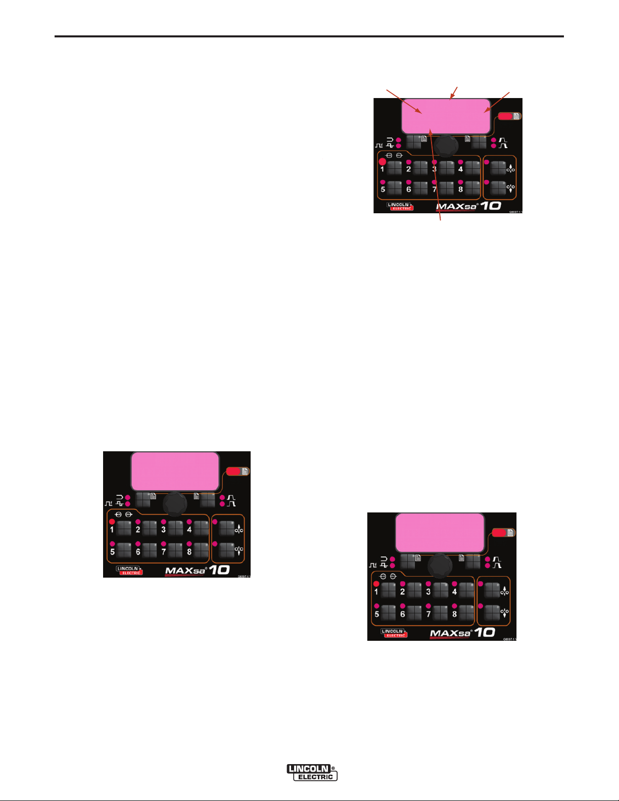
B-18
Memory 1
Set Limits
200
Hi=1050 Lo= 200
Weld Amps
Set High
Limit
V
alue
L
ow Limit
Set Low
Limit
Parameter
N
ame
Save Limits
Yes No
OPERATION
OPTIONAL LIMIT SETUP
The Limits feature allows the operator to set minimum
and maximum values for various parameters depending
on the Weld Mode selected.
Each memory location may have a different set of limits,
even if the Weld Mode is the same. For example:
Memory Location 1 can be set for a maximum wire feed
speed of 140”/min; Memory Location 2 may be set for a
minimum of 100”/min and a maximum of 160”/min and
Memory Location 3 may have no WFS limit set.
Parameters are constrained by the machine limitations or
by memory limits. When the Memory Limits are enabled
the parameter will flash if an attempt is made to set a
value outside of the prescribed limit (if less than the
machine capabilities). The parameter will not flash if an
attempt is made to exceed the machine limits.
NOTE: Weld Modes cannot be selected through the
Limits Setup Menu. They must be chosen and
saved before entering the Limits Menu.
SETTING LIMITS
1. Press and hold the desired Memory Button until
the LED for that location begins to blink rapidly.
• The MSP Display will read:
B-18
3. The Parameter Name on the MSP Display will
flash to indicate it is ready to be changed. If no limits were previously set, the High and Low values
are the limits of the Power Source
• Press the Arc Start/End Options button to select
that parameter.
• Use the Mode Select Panel Control to adjust the
High Limit (flashing).
• Press the Arc Start/End Options button.
• Use the Mode Select Panel Control to adjust the
Value (flashing).
• Press the Arc Start/End Options button.
• Use the Mode Select Panel Control to adjust the
Low Limit (flashing).
• Press the Arc Start/End Options button.
• Use the Mode Select Panel Control to select
another Parameter Name (flashing) and repeat
the above sequence until all Limits are set.
2. After 2 seconds the display will change to show the
following items:
• Memory Value
• High Limit
• Low Limit
• Parameter Name
4. Press the selected Memory when all limits are set
to desired values. The MSP Display will read:
• Use the Weld Mode Select or the Arc Start/End
Options button to either save (yes) or discard
(no) the changes.
MAXsa™ 10 CONTROLLER
Page 34

C-1
ACCESSORIES
OPTIONS AND ACCESSORIES are
available at www.lincolnelectric.com
Follow these steps:
1. Go to www.lincolnelectric.com
2. In the Search field type E9.181 and click on the
Search icon (or hit ‘Enter’ on the keyboard).
3. On the Results page, scroll down to the
Equipment list and click on E9.181.
All of the information for the PowerWave System
accessories can be found in this document.
C-1
MAXsa™ 10 CONTROLLER
Page 35

D-1
MAINTENANCE
D-1
SAFETY PRECAUTIONS
WARNING
ELECTRIC SHOCK can kill.
• Do not touch electrically live parts
such as output terminals or internal
wiring.
• When inching, electrode and drive
mechanism are “hot” to work and
ground and could remain energized
several seconds after the inch button is released.
• Turn OFF input power at welding power source
before installation or changing drive roll and/or
guide tubes.
• Welding power source must be connected to
system ground per the National Electrical Code
or any applicable local codes.
• Only qualified personnel should perform maintenance work.
------------------------------------------------------------------------
ROUTINE MAINTENANCE
• Check weld cables, control cables and gas hoses
for cuts.
PERIODIC MAINTENANCE
• N/A
CALIBRATION SPECIFICATION
All calibration is factory set on the MAXsa™ 10 CONTROLLER.
See add it iona l wa rnin g in form atio n
throughout this operator’s manual and
the Engine manual as well.
------------------------------------------------------------------------
MAXsa™ 10 CONTROLLER
Page 36

E-1
TROUBLESHOOTING
HOW TO USE TROUBLESHOOTING GUIDE
WARNING
Service and Repair should only be performed by Lincoln Electric Factory Trained Personnel.
Unauthorized repairs performed on this equipment may result in danger to the technician and
machine operator and will invalidate your factory warranty. For your safety and to avoid Electrical
Shock, please observe all safety notes and precautions detailed throughout this manual.
__________________________________________________________________________
E-1
This Troubleshooting Guide is provided to help you
locate and repair possible machine malfunctions.
Simply follow the three-step procedure listed below.
Step 1. LOCATE PROBLEM (SYMPTOM).
Look under the column labeled “PROBLEM (SYMPTOMS)”. This column describes possible symptoms
that the machine may exhibit. Find the listing that
best describes the symptom that the machine is
exhibiting.
Step 2. POSSIBLE CAUSE.
The second column labeled “POSSIBLE CAUSE” lists
the obvious external possibilities that may contribute
to the machine symptom.
Step 3. RECOMMENDED COURSE OF ACTION
This column provi des a co urse of action for the
Possible Cause, generally it states to contact your
local Lincoln Authorized Field Service Facility.
If you do not understand or are unable to perform the
Recommended Course of Action safely, contact your
local Lincoln Authorized Field Service Facility.
CAUTION
If for any reason you do not understand the test procedures or are unable to perform the tests/repairs safely, contact your
Local Lincoln Authorized Field Service Facility for technical troubleshooting assistance before you proceed.
MAXs™ 10 CONTROLLER
Page 37

E-2
TROUBLESHOOTING
Observe all Safety Guidelines detailed throughout this manual
USING THE STATUS LED TO TROUBLESHOOT
SYSTEM PROBLEMS
The MAXsa 10 is equipped with a Status Light. If a problem occurs it is
important to note the condition of the status lights. Therefore, prior to
cycling power to the system, check the power source status light
for error sequences as noted below.
Included in this section is information about the power source and
Wire Drive Module Status LED’s, and some basic troubleshooting
charts for both machine and weld performance.
The STATUS LIGHTS are dual-color LED’s that indicate system
errors. Normal operation for each is steady green. Error conditions
are indicated in the following Table E.1.
TABLE E.1
Light
Condition
Meaning
E-2
Steady Green
Blinking Green
Fast Blinking Green
Alternating Green and Red
System OK. Power source is operational, and is communicating normally with all healthy
peripheral equipment connected to its ArcLink network.
Occurs during power up or a system reset, and indicates the POWER
WAVE® i400 is mapping (identifying) each component in the system. Normal
for first 1-10 seconds after power is turned on, or if the system configuration is
changed during operation.
Under normal conditions indicates Auto-mapping has failed.
Also used by the Diagnostics Utility (included on the POWER WAVE® Utilities
and Service Navigator CD’s or available at www.powerwavesoftware.com) to
identify the selected machine when connecting to a specific IP address.
Non-recoverable system fault. If the Status lights are flashing any combination
of red and green, errors are present. Read the error code(s) before the
machine is turned off.
Error Code interpretation through the Status light is detailed in the Service
Manual. Individual code digits are flashed in red with a long pause between
digits. If more than one code is present, the codes will be separated by a
green light. Only active error conditions will be accessible through the Status
Light.
Error codes can also be retrieved with the Diagnostics Utility (included on the
POWER WAVE ® U til ities and Service Navigator CD’s or availab le at
www.powerwavesoftware.com). This is the preferred method, since it can
access historical information contained in the error log.
To clear the active error(s), turn power source off, and back on to reset.
Steady Red
Blinking Red
Not applicable.
Not applicable.
CAUTION
If for any reason you do not understand the test procedures or are unable to perform the tests/repairs safely, contact your
Local Lincoln Authorized Field Service Facility for technical troubleshooting assistance before you proceed.
MAXsa™ 10 CONTROLLER
Page 38

E-3
Observe all Safety Guidelines detailed throughout this manual
PROBLEMS
(SYMPTOMS)
ARCLINK SYSTEM ERROR CODES
Err 31 Primary overcurrent
TROUBLESHOOTING
POSSIBLE
CAUSE
1. The power source has exceeded
input current limits. Adjust the
welding procedure to reduce the
current draw. The welding procedure may exceed the capacity of
the power source.
2. See the power source Instruction
Manual.
E-3
RECOMMENDED
COURSE OF ACTION
Err 32 Capacitor bank "A" under
voltage.
Err 33 Capacitor bank "B" under
voltage.
Err 34 Capacitor bank "A" overvolt-
age.
1. The power source input power
may be wired incorrectly. Verify
the pow e r s ou r c e r e co n n ec t
panel wiring matches the input
power.
2. See the power source Instruction
Manual.
1. The power source input power
may be wired incorrectly. Verify
the power source reconnect panel
wiring matches the input power.
2. See the power source Instruction
Manual.
1. The power source input power
may be wired incorrectly. Verify
the pow e r s ou r c e r e co n n ec t
panel wiring matches the input
power.
2. See the power source Instruction
Manual.
If all recommended possible areas of
misadjustment have been checked
and the problem persists, Contact
your local Lincoln Authorized Field
Service Facility.
CAUTION
If for any reason you do not understand the test procedures or are unable to perform the tests/repairs safely, contact your
Local Lincoln Authorized Field Service Facility for technical troubleshooting assistance before you proceed.
MAXsa™ 10 CONTROLLER
Page 39
E-4
Observe all Safety Guidelines detailed throughout this manual
PROBLEMS
(SYMPTOMS)
ARCLINK SYSTEM ERROR CODES
TROUBLESHOOTING
POSSIBLE
CAUSE
E-4
RECOMMENDED
COURSE OF ACTION
Err 35 Capacitor bank "B" overvolt-
age.
Err 36 Thermal
Err 41 Long term secondary over-
current.
Err 43 Capacitors are out of bal-
ance
1. The power source input power
may be wired incorrectly. Verify
the pow e r so u r ce re c on n e ct
panel wiring matches the input
power.
2. See the power source Instruction
Manual.
1. Power source overheating. Verify
duty cycle is correct. Ensure adequate a i r fl o w a r ou n d p ow e r
source.
1. The power source has exceeded
the output current limits. Adjust
the welding procedure to reduce
the current draw. The welding
proced u r e may e xc e e d the
capacity of the power source.
2. See the power source Instruction
Manual.
1. Verify the power source recon-
nect panel wiring matches the
input power.
If all recommended possible areas of
misadjustment have been checked
and the problem persists, Contact
your local Lincoln Authorized Field
Service Facility.
2. See the power source Instruction
Manual.
CAUTION
If for any reason you do not understand the test procedures or are unable to perform the tests/repairs safely, contact your
Local Lincoln Authorized Field Service Facility for technical troubleshooting assistance before you proceed.
MAXsa™ 10 CONTROLLER
Page 40

E-5
TROUBLESHOOTING
Observe all Safety Guidelines detailed throughout this manual
E-5
PROBLEMS
(SYMPTOMS)
ARCLINK SYSTEM ERROR CODES
Err 44 Main CPU problem.
Err 53 Voltage sense loss.
Err 54 Short term secondary over-
current.
Err 81 Motor overload, long term.
POSSIBLE
CAUSE
1. Verify the earth ground connection to the power source is wired
correctly.
2. See the power source Instruction
Manual.
1. Verify correct sense lead connection.
1. The wire drive motor has overheated. Check that the electrode
slides easily through the gun and
cable.
2. Remove tight bends from the gun
and cable.
3. Check that the spindle brake is
not too tight.
4. Verify a high quality electrode is
being used.
5. Wait for the error to reset and the
motor to cool (approximately 1
minute).
6. Long term average motor current
limit has bee n e x c e ed e d .
Typically indicates mechanical
overload of system. If problem
continues consider higher torque
gear ratio (lower speed range).
RECOMMENDED
COURSE OF ACTION
If all recommended possible areas
of misadjustment have been
checked and the problem persists,
Contact your local Lincoln
Authorized Field Service Facility.
Err 82 Motor overload, short term.
1. The wire drive motor current draw
has exceeded limit s , us u a l ly
because the motor is in a locked
rotor state. Check that motor can
turn freely when idle arm is open.
2. Verify that the gears are free of
debris and dirt.
CAUTION
If for any reason you do not understand the test procedures or are unable to perform the tests/repairs safely, contact your
Local Lincoln Authorized Field Service Facility for technical troubleshooting assistance before you proceed.
MAXsa™ 10 CONTROLLER
Page 41

E-6
Observe all Safety Guidelines detailed throughout this manual
PROBLEMS
(SYMPTOMS)
ARCLINK SYSTEM ERROR CODES
Err 263 No usable weld modes. 1. The power source does not have
Below are errors implemented for the MAXsa™ 10.
TROUBLESHOOTING
POSSIBLE
CAUSE
any welding programs loaded.
2. See the power source Instruction
Manual fo r load we l d in g programs.
E-6
RECOMMENDED
COURSE OF ACTION
If all recommended possible areas of
misadjustment have been checked
and the problem persists, Contact
your local Lincoln Authorized Field
Service Facility.
Error
Code
N/A
28
83
84
Typical User Interface 3 digit error codes (not blinked on the status LED).
Error
Code
213
215
247
274
275
276
277
278
281
282
Source
User Interface
Feeder
Feeder
Feeder
Source
User Interface
“OUTPUT DISABLED”
Feeder Board is Off-Line
UI Text
" Limits Exceed "
"Gear Box Type"
" UI Shutdown 1 "
" UI Shutdown 2 "
UI Text
Power Source
is Off-Line
N/A
N/A
N/A
N/A
N/A
N/A
(Varies based on the
error type and who
caused the error)
(Varies based on the
error type and who
caused the error)
When a mode is selected with a work point low limit
greater than the high WFS limit. (no event is logged)
The shutdown 2 input on the Feeder Board is open and
P.21 is selected for “Output Disable”
The shutdown 1 input on the Feeder Board is open.
The shutdown 2 input on the Feeder Board is open.
User Interface could not communicate with control board
in power source.
Either no feed head board is connected, being repro-
grammed or experiencing a fatal event.
Arc control has a latched fault. The UI will indicate a
Reset button needs to be pressed to clear the fault.
Weld set change required clearing of user memory.
UI memory could not be saved. Contact Lincoln Electric
Service Department for further support.
UI memory could not be restored. Contact Lincoln
Electric Service Department for further support.
UI memories were converted due to change in number of
UI parameters. Info only.
UI limits were converted due to change in number of UI
parameters with limits. Info only.
Internal Error. Collect all displayed values and contact
Lincoln Electric Service Department.
Internal Error. Collect all displayed values and contact
Lincoln Electric Service Department.
Reason
Reason
CAUTION
If for any reason you do not understand the test procedures or are unable to perform the tests/repairs safely, contact your
Local Lincoln Authorized Field Service Facility for technical troubleshooting assistance before you proceed.
MAXsa™ 10 CONTROLLER
Page 42

E-7
Typical User Interface 3 digit error codes (not blinked on the status LED).
TROUBLESHOOTING
E-7
Error
Code
283
285
612
Source
User Interface
Observe all Safety Guidelines detailed throughout this manual
(Varies based on the
error type and who
caused the error)
{" Phase Gen Init "},
{"Duplicate Arc # "},
{" Mult Lead Arcs "},
{" Missing an Arc "},
{" Too Many Arcs "},
{"Missing Lead Arc"},
{" Missing an Arc "}
PROBLEMS
(SYMPTOMS)
OUTPUT PROBLEMS
The feeder does not power up - no
display, no feed.
UI Text
Internal Error. Collect all displayed values and contact
Lincoln Electric Service Department.
N/A
UI memory could not be restored. Contact Lincoln
Electric Service Department for further support.
1 = Initializing Phase Generator
7 = Trail Arc dropped communication with Lead Arc
POSSIBLE
CAUSE
1. The Power Wave power source is
OFF. Turn ON the Power Wave
source.
Reason
2 = Duplicate Arc #'s found
3 = Mult Lead Arcs found
4 = Missing a Trail Arc
5 = Too Many Arcs
6 = Missing Lead Arc
RECOMMENDED
COURSE OF ACTION
2. The circuit breaker for the wire
feeder on power source ha s
tripped. Reset the circuit breakers.
3. The control cable may be loose
or damaged. Tighten, repair or
replace the control cable.
4. The power switch is damaged.
Replace the power switch.
If all recommended possible areas of
misadjustment have been checked
and the problem persists, Contact
your local Lincoln Authorized Field
Service Facility.
CAUTION
If for any reason you do not understand the test procedures or are unable to perform the tests/repairs safely, contact your
Local Lincoln Authorized Field Service Facility for technical troubleshooting assistance before you proceed.
MAXsa™ 10 CONTROLLER
Page 43

E-8
Observe all Safety Guidelines detailed throughout this manual
PROBLEMS
(SYMPTOMS)
OUTPUT PROBLEMS
Inconsistent wire feeding or wire not
feeding but drive rolls turning.
TROUBLESHOOTING
POSSIBLE
CAUSE
1. The electrode is rusty or dirty. Use
only clean electrode. Use quality
electrode, like L-50 or L-56 from
Lincoln Electric.
2. The contact tip is partially melted
or has spatter. Replace the contact tip.
3. Improper tip, drive rolls and/or
inner wire guide. Verify the proper parts are installed.
4. Incorrect tension arm pressure on
the drive rolls. Adjust the tension
arm per the Instruction Manual.
Most electrodes feed well at a
tension arm setting of "3".
E-8
RECOMMENDED
COURSE OF ACTION
Wire feed speed consistently operates at the wrong value.
Variable or "hunting" arc.
5. Worn dr i v e roll. Replace the
drive rolls if worn or filled with
dirt.
1. The wire feeder gear setting is
not properly set. Verify that the
software setting matches the gear
mounte d. See the Instruction
Manual for setting the gear ratio.
1. Wrong size, worn and/or melted
contact tip. Replace the contact
tip.
2. Worn work cable or poor work
connection. Verify all work and
electrode connections are tight
and that the cables are in good
condition. Clean/replace as necessary.
3. Wrong polarity. Adjust polarity to
the recomm e n d ed pr o c edure.
Verify DIP sw i tc h #7 setting
matches the electrode polarity.
If all recommended possible areas of
misadjustment have been checked
and the problem persists, Contact
your local Lincoln Authorized Field
Service Facility.
CAUTION
If for any reason you do not understand the test procedures or are unable to perform the tests/repairs safely, contact your
Local Lincoln Authorized Field Service Facility for technical troubleshooting assistance before you proceed.
MAXsa™ 10 CONTROLLER
Page 44

F-1
Enhanced Diagram
DIAGRAMS
F-1
MAXsa™ 10 CONTROLLER
NOTE: This diagram is for reference only. It may not be accurate for all machines covered by this manual. The specific diagram for a particular code is pasted inside the
machine on one of the enclosure panels. If the diagram is illegible, write to the Service Department for a replacement. Give the equipment code number.
Page 45
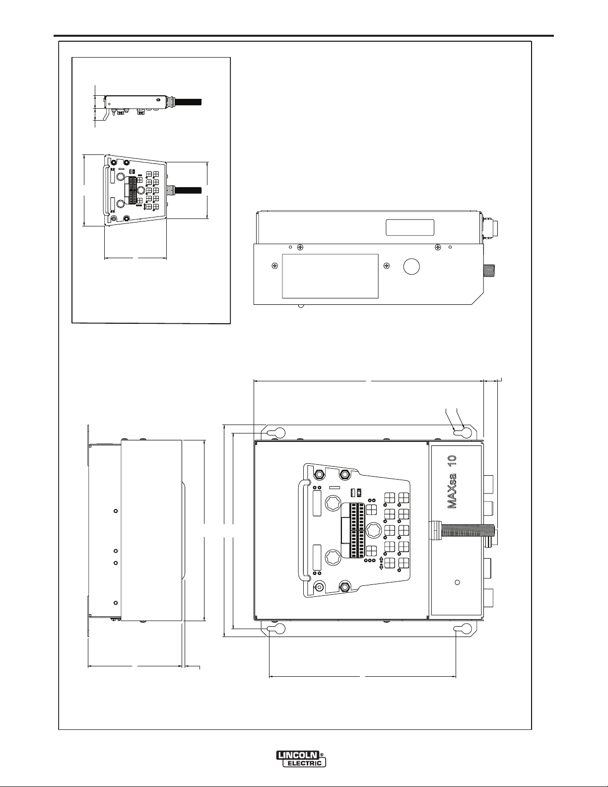
F-2
5.89
.20
11.30
13.25
12.25
11.68
O .66
O .28
14.40
.87
7.75
8.90
7.07
1.641.50
SCALE = 1 : 4
PENDANT
L13444
DIMENSION PRINT
F-2
MAXsa™ 10 CONTROLLER
Page 46

WARNING
Spanish
AVISO DE
PRECAUCION
• Do not touch electrically live parts or
electrode with skin or wet clothing.
• Insulate yourself from work and
ground.
• No toque las partes o los electrodos
bajo carga con la piel o ropa mojada.
• Aislese del trabajo y de la tierra.
• Keep flammable materials away.
• Mantenga el material combustible
fuera del área de trabajo.
• Wear eye, ear and body protection.
• Protéjase los ojos, los oídos y el
cuerpo.
French
ATTENTION
German
WARNUNG
Portuguese
ATENÇÃO
Japanese
Chinese
Korean
Arabic
• Ne laissez ni la peau ni des vête-
ments mouillés entrer en contact
avec des pièces sous tension.
• Isolez-vous du travail et de la terre.
• Berühren Sie keine stromführenden
Teile oder Elektroden mit Ihrem
Körper oder feuchter Kleidung!
• Isolieren Sie sich von den
Elektroden und dem Erdboden!
• Não toque partes elétricas e electro-
dos com a pele ou roupa molhada.
• Isole-se da peça e terra.
• Gardez à l’écart de tout matériel
inflammable.
• Entfernen Sie brennbarres Material!
• Mantenha inflamáveis bem guarda-
dos.
• Protégez vos yeux, vos oreilles et
votre corps.
• Tragen Sie Augen-, Ohren- und Kör-
perschutz!
• Use proteção para a vista, ouvido e
corpo.
READ AND UNDERSTAND THE MANUFACTURER’S INSTRUCTION FOR THIS EQUIPMENT AND THE
CONSUMABLES TO BE USED AND FOLLOW YOUR EMPLOYER’S SAFETY PRACTICES.
SE RECOMIENDA LEER Y ENTENDER LAS INSTRUCCIONES DEL FABRICANTE PARA EL USO DE
ESTE EQUIPO Y LOS CONSUMIBLES QUE VA A UTILIZAR, SIGA LAS MEDIDAS DE SEGURIDAD DE SU
SUPERVISOR.
LISEZ ET COMPRENEZ LES INSTRUCTIONS DU FABRICANT EN CE QUI REGARDE CET EQUIPMENT
ET LES PRODUITS A ETRE EMPLOYES ET SUIVEZ LES PROCEDURES DE SECURITE DE VOTRE
EMPLOYEUR.
LESEN SIE UND BEFOLGEN SIE DIE BETRIEBSANLEITUNG DER ANLAGE UND DEN ELEKTRODENEINSATZ DES HERSTELLERS. DIE UNFALLVERHÜTUNGSVORSCHRIFTEN DES ARBEITGEBERS
SIND EBENFALLS ZU BEACHTEN.
Page 47

• Keep your head out of fumes.
• Use ventilation or exhaust to
remove fumes from breathing zone.
• Turn power off before servicing.
• Do not operate with panel open or
guards off.
WARNING
• Los humos fuera de la zona de res-
piración.
• Mantenga la cabeza fuera de los
humos. Utilice ventilación o
aspiración para gases.
• Gardez la tête à l’écart des fumées.
• Utilisez un ventilateur ou un aspira-
teur pour ôter les fumées des zones
de travail.
• Vermeiden Sie das Einatmen von
Schweibrauch!
• Sorgen Sie für gute Be- und
Entlüftung des Arbeitsplatzes!
• Mantenha seu rosto da fumaça.
• Use ventilação e exhaustão para
remover fumo da zona respiratória.
• Desconectar el cable de ali-
mentación de poder de la máquina
antes de iniciar cualquier servicio.
• Débranchez le courant avant l’entre-
tien.
• Strom vor Wartungsarbeiten
abschalten! (Netzstrom völlig öffnen;
Maschine anhalten!)
•
Não opere com as tampas removidas.
•
Desligue a corrente antes de fazer
serviço.
•
Não toque as partes elétricas nuas.
• No operar con panel abierto o
guardas quitadas.
• N’opérez pas avec les panneaux
ouverts ou avec les dispositifs de
protection enlevés.
• Anlage nie ohne Schutzgehäuse
oder Innenschutzverkleidung in
Betrieb setzen!
• Mantenha-se afastado das partes
moventes.
• Não opere com os paineis abertos
ou guardas removidas.
Spanish
AVISO DE
PRECAUCION
French
ATTENTION
German
WARNUNG
Portuguese
ATENÇÃO
Japanese
Chinese
Korean
Arabic
LEIA E COMPREENDA AS INSTRUÇÕES DO FABRICANTE PARA ESTE EQUIPAMENTO E AS PARTES
DE USO, E SIGA AS PRÁTICAS DE SEGURANÇA DO EMPREGADOR.
Page 48

• World's Leader in Welding and Cutting Products •
• Sales and Service through Subsidiaries and Distributors Worldwide •
Cleveland, Ohio 44117-1199 U.S.A. TEL: 216.481.8100 FAX: 216.486.1751 WEB SITE: www.lincolnelectric.com
 Loading...