

Page 1
IM10018-A
1
2
3
4
5
6
7
8
9
10
RETURN TO MAIN MENU
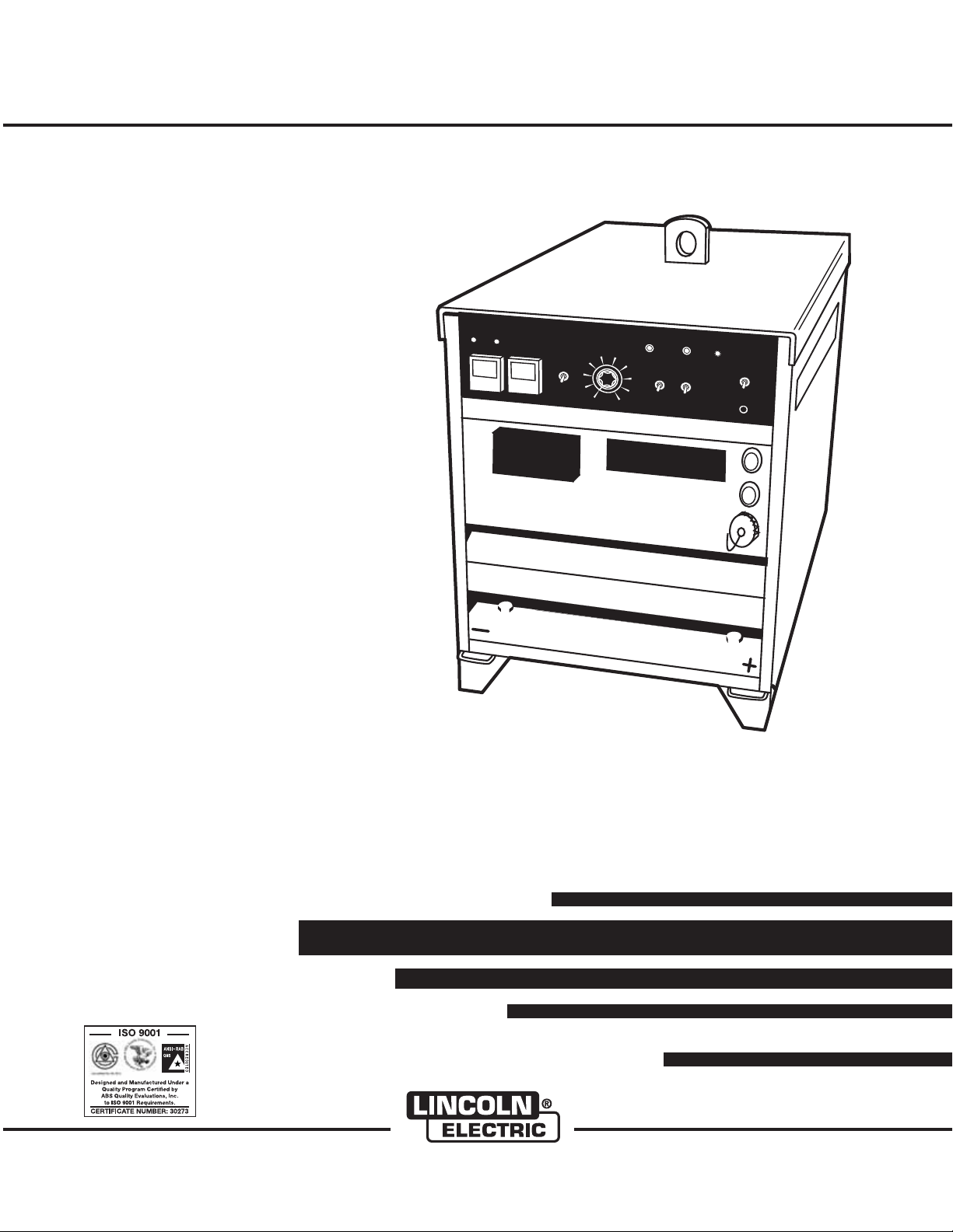
IDEALARC ®DC-600 VRD
For use with machines having Code Numbers:
Safety Depends on You
Lincoln arc welding and cutting
equipment is designed and built
with safety in mind. However,
your overall safety can be
increased by proper installation
... and thoughtful operation on
your part. DO NOT INSTALL,
OPERATE OR REPAIR THIS
EQUIPMENT WITHOUT READING THIS MANUAL AND THE
SAFETY PRECAUTIONS CONTAINED THROUGHOUT. And,
most importantly, think before
you act and be careful.
August, 2011
11598, 11613, 11707, 11725
DC-600 VRD
Equipped with VRD (VOLTAGE REDUCTION DEVICE)
See Operation Section for an explanation.
Cleveland, Ohio 44117-1199 U.S.A. TEL: 216.481.8100 FAX: 216.486.1751 WEB SITE: www.lincolnelectric.com
IEC 60974-1
IP23
OPERATORʼS MANUAL
Copyright © Lincoln Global Inc.
• World's Leader in Welding and Cutting Products •
• Sales and Service through Subsidiaries and Distributors Worldwide •
Page 2
i
SAFETY
i
WARNING
CALIFORNIA PROPOSITION 65 WARNINGS
Diesel engine exhaust and some of its constituents
are known to the State of California to cause cancer, birth defects, and other reproductive harm.
The Above For Diesel Engines
ARC WELDING CAN BE HAZARDOUS. PROTECT YOURSELF AND OTHERS FROM POSSIBLE SERIOUS INJURY OR DEATH.
KEEP CHILDREN AWAY. PACEMAKER WEARERS SHOULD CONSULT WITH THEIR DOCTOR BEFORE OPERATING.
Read and understand the following safety highlights. For additional safety information, it is strongly recommended that you
purchase a copy of “Safety in Welding & Cutting - ANSI Standard Z49.1” from the American Welding Society, P.O. Box
351040, Miami, Florida 33135 or CSA Standard W117.2-1974. A Free copy of “Arc Welding Safety” booklet E205 is available
from the Lincoln Electric Company, 22801 St. Clair Avenue, Cleveland, Ohio 44117-1199.
BE SURE THAT ALL INSTALLATION, OPERATION, MAINTENANCE AND REPAIR PROCEDURES ARE
PERFORMED ONLY BY QUALIFIED INDIVIDUALS.
The engine exhaust from this product contains
chemicals known to the State of California to cause
cancer, birth defects, or other reproductive harm.
The Above For Gasoline Engines
FOR ENGINE
powered equipment.
1.a. Turn the engine off before troubleshooting and maintenance
work unless the maintenance work requires it to be running.
____________________________________________________
1.b. Operate engines in open, well-ventilated
areas or vent the engine exhaust fumes
outdoors.
____________________________________________________
1.c. Do not add the fuel near an open flame
welding arc or when the engine is running.
Stop the engine and allow it to cool before
refueling to prevent spilled fuel from vaporizing on contact with hot engine parts and
igniting. Do not spill fuel when filling tank. If
fuel is spilled, wipe it up and do not start
engine until fumes have been eliminated.
____________________________________________________
1.d. Keep all equipment safety guards, covers and devices in
position and in good repair.Keep hands, hair, clothing and
tools away from V-belts, gears, fans and all other moving
parts when starting, operating or repairing equipment.
____________________________________________________
1.e. In some cases it may be necessary to remove safety
guards to perform required maintenance. Remove
guards only when necessary and replace them when the
maintenance requiring their removal is complete.
Always use the greatest care when working near moving
parts.
___________________________________________________
1.f. Do not put your hands near the engine fan.
Do not attempt to override the governor or
idler by pushing on the throttle control rods
while the engine is running.
1.h. To avoid scalding, do not remove the
radiator pressure cap when the engine is
hot.
ELECTRIC AND
MAGNETIC FIELDS
may be dangerous
2.a. Electric current flowing through any conductor causes
localized Electric and Magnetic Fields (EMF). Welding
current creates EMF fields around welding cables and
welding machines
2.b. EMF fi elds m ay interf ere wi th some pacemak ers, a nd
welders having a pacemaker should consult their physician
before welding.
2.c. Exposure to EMF fields in welding may have other health
effects which are now not known.
2.d. All welders should use the following procedures in order to
minimize exposure to EMF fields from the welding circuit:
2.d.1.
Route the electrode and work cables together - Secure
them with tape when possible.
2.d.2. Never coil the electrode lead around your body.
2.d.3. Do not place your body between the electrode and
work cables. If the electrode cable is on your right
side, the work cable should also be on your right side.
___________________________________________________
1.g. To prevent accidentally starting gasoline engines while
turning the engine or welding generator during maintenance
work, disconnect the spark plug wires, distributor cap or
magneto wire as appropriate.
IDEALARC®DC-600 VRD
2.d.4. Connect the work cable to the workpiece as close as
possible to the area being welded.
2.d.5. Do not work next to welding power source.
Page 3
ii
SAFETY
ii
ELECTRIC SHOCK can
kill.
3.a. The electrode and work (or ground) circuits
are electrically “hot” when the welder is on.
Do not touch these “hot” parts with your bare
skin or wet clothing. Wear dry, hole-free
gloves to insulate hands.
3.b. Insulate yourself from work and ground using dry insulation.
Make certain the insulation is large enough to cover your full
area of physical contact with work and ground.
In addition to the normal safety precautions, if welding
must be performed under electrically hazardous
conditions (in damp locations or while wearing wet
clothing; on metal structures such as floors, gratings or
scaffolds; when in cramped positions such as sitting,
kneeling or lying, if there is a high risk of unavoidable or
accidental contact with the workpiece or ground) use
the following equipment:
• Semiautomatic DC Constant Voltage (Wire) Welder.
• DC Manual (Stick) Welder.
• AC Welder with Reduced Voltage Control.
3.c. In semiautomatic or automatic wire welding, the electrode,
electrode reel, welding head, nozzle or semiautomatic
welding gun are also electrically “hot”.
3.d. Always be sure the work cable makes a good electrical
connection with the metal being welded. The connection
should be as close as possible to the area being welded.
3.e. Ground the work or metal to be welded to a good electrical
(earth) ground.
3.f.
Maintain the electrode holder, work clamp, welding cable and
welding machine in good, safe operating condition. Replace
damaged insulation.
3.g. Never dip the electrode in water for cooling.
3.h. Never simultaneously touch electrically “hot” parts of
electrode holders connected to two welders because voltage
between the two can be the total of the open circuit voltage
of both welders.
3.i. When working above floor level, use a safety belt to protect
yourself from a fall should you get a shock.
3.j. Also see Items 6.c. and 8.
ARC RAYS can burn.
4.a. Use a shield with the proper filter and cover
plates to protect your eyes from sparks and
the rays of the arc when welding or observing
open arc welding. Headshield and filter lens
should conform to ANSI Z87. I standards.
4.b. Use suitable clothing made from durable flame-resistant
material to protect your skin and that of your helpers from
the arc rays.
4.c. Protect other nearby personnel with suitable, non-flammable
screening and/or warn them not to watch the arc nor expose
themselves to the arc rays or to hot spatter or metal.
FUMES AND GASES
can be dangerous.
5.a. Welding ma y produce fumes and gases
hazardous to health. Avoid breathing these
fumes and gases. When welding, keep
your head out of the fume. Use enough
ventilation and/or exhaust at the arc to keep
fumes and gases away from the breathing zone. When
welding with electrodes which require special
ventilation such as stainless or hard facing (see
instructions on container or MSDS) or on lead or
cadmium plated steel and other metals or coatings
which produce highly toxic fumes, keep exposure as
low as possible and within applicable OSHA PEL and
ACGIH TLV limits using local exhaust or mechanical
ventilation. In confined spaces or in some circumstances, outdoors, a respirator may be required.
Additional precautions are also required when welding
on galvanized steel.
5. b. The operation of welding fume control equipment is affected
by various factors including proper use and positioning of
the equipment, maintenance of the equipment and the specific welding procedure and application involved. Worker
exposure level should be checked upon installation and
periodically thereafter to be certain it is within applicable
OSHA PEL and ACGIH TLV limits.
5.c.
Do not weld in locations near chlorinated hydrocarbon
coming from degreasing, cleaning or spraying operations.
The heat and rays of the arc can react with solvent vapors
form phosgene, a highly toxic gas, and other irritating products.
5.d. Shielding gases used for arc welding can displace air and
cause injury or death. Always use enough ventilation,
especially in confined areas, to insure breathing air is safe.
vapors
to
5.e. Read and understand the manufacturer’s instructions for this
equipment and the consumables to be used, including the
material safety data sheet (MSDS) and follow your
employer’s safety practices. MSDS forms are available from
your welding distributor or from the manufacturer.
5.f. Also see item 1.b.
IDEALARC®DC-600 VRD
Page 4
iii
SAFETY
iii
WELDING and CUTTING
SPARKS can
cause fire or explosion.
6.a.
Remove fire hazards from the welding area.
If this is not possible, cover them to prevent
Remember that welding sparks and hot
materials from welding can easily go through small cracks
and openings to adjacent areas. Avoid welding near
hydraulic lines. Have a fire extinguisher readily available.
6.b. Where compressed gases are to be used at the job site,
special precautions should be used to prevent hazardous
situations. Refer to “Safety in Welding and Cutting” (ANSI
Standard Z49.1) and the operating information for the
equipment being used.
6.c. When not welding, make certain no part of the electrode
circuit is touching the work or ground. Accidental contact
can cause overheating and create a fire hazard.
6.d. Do not heat, cut or weld tanks, drums or containers until the
proper steps have been taken to insure that such procedures
will not cause flammable or toxic vapors from substances
inside. They can cause an explosion even
been “cleaned”. For information, purchase “Recommended
Safe Practices for the
Containers and Piping That Have Held Hazardous
Substances”, AWS F4.1 from the American Welding Society
(see address above).
6.e. Vent hollow castings or containers before heating, cutting or
welding. They may explode.
Sparks and spatter are thrown from the welding arc. Wear oil
6.f.
free protective garments such as leather gloves, heavy shirt,
cuffless trousers, high shoes and a cap over your hair. Wear
ear plugs when welding out of position or in confined places.
Always wear safety glasses with side shields when in a
welding area.
6.g. Connect the work cable to the work as close to the welding
area as practical. Work cables connected to the building
framework or other locations away from the welding area
increase the possibility of the welding current passing
through lifting chains, crane cables or other alternate circuits. This can create fire hazards or overheat lifting chains
or cables until they fail.
6.h. Also see item 1.c.
the welding sparks from starting a fire.
though
they have
Preparation
for Welding and Cutting of
CYLINDER may explode
if damaged.
7.a. Us e on ly compr es sed ga s cylinders
containing the correct shielding gas for the
process used and properly operating
regulators designed for the gas and
pressure used. All hoses, fittings, etc. should be suitable for
the application and maintained in good condition.
7.b. Alway s keep cylin ders i n an up right position securely
chained to an undercarriage or fixed support.
7.c. Cylinders should be located:
• Away from areas where they may be struck or subjected to
physical damage.
• A safe distance from arc welding or cutting operations and
any other source of heat, sparks, or flame.
7.d. Never allow the electrode, electrode holder or any other
electrically “hot” parts to touch a cylinder.
7.e. Keep your head and face away from the cylinder valve outlet
when opening the cylinder valve.
7.f. Valve protection caps should always be in place and hand
tight except when the cylinder is in use or connected for
use.
7.g. Re ad and foll ow the inst ru ctions o n c ompressed gas
cylinders, associated equipment, and CGA publication P-l,
“Precautions for Safe Handling of Compressed Gases in
Cylinders,” available from the Compressed Gas Association
1235 Jefferson Davis Highway, Arlington, VA 22202.
FOR ELECTRICALLY
powered equipment.
8.a. Turn off input power using the disconnect
switch at the fuse box before working on
the equipment.
8.b. Install equipment in accordance with the U.S. National
Electrical Code, all local codes and the manufacturer’s
recommendations.
8.c. Ground the equipment in accordance with the U.S. National
Electrical Code and the manufacturer’s recommendations.
6.I. Read and follow NFPA 51B “ Standard for Fire Prevention
During Welding, Cutting and Other Hot Work”, available
from NFPA, 1 Batterymarch Park, PO box 9101, Quincy, Ma
022690-9101.
6.j. Do not use a welding power source for pipe thawing.
Refer to http://www.lincolnelectric.com/safety for additional safety information.
IDEALARC®DC-600 VRD
Page 5

iv
SAFETY
iv
PRÉCAUTIONS DE SÛRETÉ
Pour votre propre protection lire et observer toutes les instructions
et les précautions de sûreté specifiques qui parraissent dans ce
manuel aussi bien que les précautions de sûreté générales suivantes:
Sûreté Pour Soudage A L’Arc
1. Protegez-vous contre la secousse électrique:
a. Les circuits à l’électrode et à la piéce sont sous tension
quand la machine à souder est en marche. Eviter toujours
tout contact entre les parties sous tension et la peau nue
ou les vétements mouillés. Porter des gants secs et sans
trous pour isoler les mains.
b. Faire trés attention de bien s’isoler de la masse quand on
soude dans des endroits humides, ou sur un plancher
metallique ou des grilles metalliques, principalement dans
les positions assis ou couché pour lesquelles une grande
partie du corps peut être en contact avec la masse.
c. Maintenir le porte-électrode, la pince de masse, le câble
de soudage et la machine à souder en bon et sûr état
defonctionnement.
d.Ne jamais plonger le porte-électrode dans l’eau pour le
refroidir.
e. Ne jamais toucher simultanément les parties sous tension
des porte-électrodes connectés à deux machines à souder
parce que la tension entre les deux pinces peut être le
total de la tension à vide des deux machines.
f. Si on utilise la machine à souder comme une source de
courant pour soudage semi-automatique, ces precautions
pour le porte-électrode s’applicuent aussi au pistolet de
soudage.
2. Dans le cas de travail au dessus du niveau du sol, se protéger
contre les chutes dans le cas ou on recoit un choc. Ne jamais
enrouler le câble-électrode autour de n’importe quelle partie
du corps.
5. Toujours porter des lunettes de sécurité dans la zone de
soudage. Utiliser des lunettes avec écrans lateraux dans les
zones où l’on pique le laitier.
6. Eloigner les matériaux inflammables ou les recouvrir afin de
prévenir tout risque d’incendie dû aux étincelles.
7. Quand on ne soude pas, poser la pince à une endroit isolé de
la masse. Un court-circuit accidental peut provoquer un
échauffement et un risque d’incendie.
8. S’assurer que la masse est connectée le plus prés possible
de la zone de travail qu’il est pratique de le faire. Si on place
la masse sur la charpente de la construction ou d’autres
endroits éloignés de la zone de travail, on augmente le risque
de voir passer le courant de soudage par les chaines de levage, câbles de grue, ou autres circuits. Cela peut provoquer
des risques d’incendie ou d’echauffement des chaines et des
câbles jusqu’à ce qu’ils se rompent.
9. Assurer une ventilation suffisante dans la zone de soudage.
Ceci est particuliérement important pour le soudage de tôles
galvanisées plombées, ou cadmiées ou tout autre métal qui
produit des fumeés toxiques.
10. Ne pas souder en présence de vapeurs de chlore provenant
d’opérations de dégraissage, nettoyage ou pistolage. La
chaleur ou les rayons de l’arc peuvent réagir avec les vapeurs
du solvant pour produire du phosgéne (gas fortement toxique)
ou autres produits irritants.
11. Pour obtenir de plus amples renseignements sur la sûreté,
voir le code “Code for safety in welding and cutting” CSA
Standard W 117.2-1974.
PRÉCAUTIONS DE SÛRETÉ POUR
3. Un coup d’arc peut être plus sévère qu’un coup de soliel,
donc:
a. Utiliser un bon masque avec un verre filtrant approprié
ainsi qu’un verre blanc afin de se protéger les yeux du rayonnement de l’arc et des projections quand on soude ou
quand on regarde l’arc.
b. Porter des vêtements convenables afin de protéger la
peau de soudeur et des aides contre le rayonnement de
l‘arc.
c. Protéger l’autre personnel travaillant à proximité au
soudage à l’aide d’écrans appropriés et non-inflammables.
4. Des gouttes de laitier en fusion sont émises de l’arc de
soudage. Se protéger avec des vêtements de protection libres
de l’huile, tels que les gants en cuir, chemise épaisse, pantalons sans revers, et chaussures montantes.
IDEALARC®DC-600 VRD
LES MACHINES À SOUDER À
TRANSFORMATEUR ET À
REDRESSEUR
1. Relier à la terre le chassis du poste conformement au code de
l’électricité et aux recommendations du fabricant. Le dispositif
de montage ou la piece à souder doit être branché à une
bonne mise à la terre.
2. Autant que possible, I’installation et l’entretien du poste seront
effectués par un électricien qualifié.
3. Avant de faires des travaux à l’interieur de poste, la debrancher à l’interrupteur à la boite de fusibles.
4. Garder tous les couvercles et dispositifs de sûreté à leur
place.
Page 6

Thank You
vv
for selecting a QUALITY product by Lincoln Electric. We want you
to take pride in operating this Lincoln Electric Company product
••• as much pride as we have in bringing this product to you!
The business of The Lincoln Electric Company is manufacturing and selling high quality welding equipment, consumables, and cutting equipment. Our challenge is to meet the needs of our customers and to exceed their expectations. On occasion, purchasers may ask Lincoln
Electric for advice or information about their use of our products. We respond to our customers based on the best information in our possession at that time. Lincoln Electric is not in a position to warrant or guarantee such advice, and assumes no liability, with respect to such information or advice. We expressly disclaim any warranty of any kind, including any warranty of fitness for any customerʼs particular purpose,
with respect to such information or advice. As a matter of practical consideration, we also cannot assume any responsibility for updating or
correcting any such information or advice once it has been given, nor does the provision of information or advice create, expand or alter any
warranty with respect to the sale of our products.
Lincoln Electric is a responsive manufacturer, but the selection and use of specific products sold by Lincoln Electric is solely within the control
of, and remains the sole responsibility of the customer. Many variables beyond the control of Lincoln Electric affect the results obtained in
applying these types of fabrication methods and service requirements.
Subject to Change – This information is accurate to the best of our knowledge at the time of printing. Please refer to www.lincolnelectric.com
for any updated information.
CUSTOMER ASSISTANCE POLICY
Please Examine Carton and Equipment For Damage Immediately
When this equipment is shipped, title passes to the purchaser upon receipt by the carrier. Consequently, Claims
for material damaged in shipment must be made by the purchaser against the transportation company at the
time the shipment is received.
Please record your equipment identification information below for future reference. This information can be
found on your machine nameplate.
Product _________________________________________________________________________________
Model Number ___________________________________________________________________________
Code Number or Date Code_________________________________________________________________
Serial Number____________________________________________________________________________
Date Purchased___________________________________________________________________________
Where Purchased_________________________________________________________________________
Whenever you request replacement parts or information on this equipment, always supply the information you
have recorded above. The code number is especially important when identifying the correct replacement parts.
On-Line Product Registration
- Register your machine with Lincoln Electric either via fax or over the Internet.
• For faxing: Complete the form on the back of the warranty statement included in the literature packet
accompanying this machine and fax the form per the instructions printed on it.
• For On-Line Registration: Go to our
Your Product”. Please complete the form and submit your registration.
Read this Operators Manual completely before attempting to use this equipment. Save this manual and keep it
handy for quick reference. Pay particular attention to the safety instructions we have provided for your protection.
The level of seriousness to be applied to each is explained below:
WEB SITE at www.lincolnelectric.com. Choose “Support” and then “Register
WARNING
This statement appears where the information must be followed exactly to avoid serious personal injury or loss of life.
CAUTION
This statement appears where the information must be followed to avoid minor personal injury or damage to this equipment.
Page 7

vi
TABLE OF CONTENTS
Page
Installation .......................................................................................................Section A
Technical Specifications ............................................................................................. A-1
Safety Precautions ..................................................................................................... A-2
Select Proper Location.................................................................................................A-2
Limit on Stacking ...................................................................................................A-2
Stacking.................................................................................................................A-2
Tilting .....................................................................................................................A-2
Electrical Input Connections ....................................................................................... A-3
Fuses and Wire Sizes............................................................................................A-3
Ground Connection .............................................................................................. A-3
Input Power Supply Connections...........................................................................A-3
Reconnect Procedure ................................................................................................ A-4
Output Connections ................................................................................................... A-5
Electrode, Work and #21 Lead ..............................................................................A-5
Auxiliary Power and Control Connections .............................................................A-6
________________________________________________________________________
Operation .........................................................................................................Section B
Safety Precautions ............................................................................................... B-1
General Description ............................................................................................. B-2
Recommended Processes and Equipment ...........................................................B-2
Design Features and Advantages ........................................................................B-2
Welding Capability ............................................................................................... B-3
Meaning of Graphical Symbols on Case Front......................................................B-3
Meaning of Graphical Symbols on Rating Plate ....................................................B-4
Meaning of Graphical Symbol for Ground Connection ..........................................B-4
Controls and Settings ....................................................................................B-4, B-5
Auxiliary Power in MS - Receptacle.......................................................................B-5
Overload, Overcurrent and Fault Protection..........................................................B-6
VRD Voltage Reduction Device Operation............................................................B-6
Operating Steps ................................................................................................... B-7
Remote Control of Machine Operation ..................................................................B-7
Welding Procedure Recommendations ............................................................... B-7
Semi-Automatic and Automatic Wire Feeding
with a IDEALARC
NA-3 Automatic Wire Feeder ..........................................................................B-8
NA-5 Automatic Wire Feeder ..........................................................................B-9
________________________________________________________________________
®
DC-600 VRD and Wire Feeders .............................................B-7
vi
Accessories.....................................................................................................Section C
Wire Feeders and Tractors....................................................................................C-1
Field Installed Options...........................................................................................C-1
Remote Output Control (K775 or K857)..........................................................C-1
Remote Control Adapter Cable (K864) ...........................................................C-1
Undercarriages (K817P, K842).......................................................................C-1
Factory or Field Installed Options..........................................................................C-1
Multi-Process Switch (K804-1)........................................................................C-1
Connections for Semi-Automatic or Automatic Wire Feeder Control ....................C-3
________________________________________________________________________
Page 8

vii
TABLE OF CONTENTS
Page
Maintenance ....................................................................................................Section D
Safety Precautions ................................................................................................D-1
Routine and Periodic Maintenance........................................................................D-1
Troubleshooting..............................................................................................Section E
Safety Precautions.................................................................................................E-1
How to Use Troubleshooting Guide.......................................................................E-1
Troubleshooting Guide ..........................................................................................E-2
Wiring Diagrams, Connection Diagrams and Dimension Prints.................Section F
Parts List....................................................................................................P-631 Series
vii
Page 9
A-1
INSTALLATION
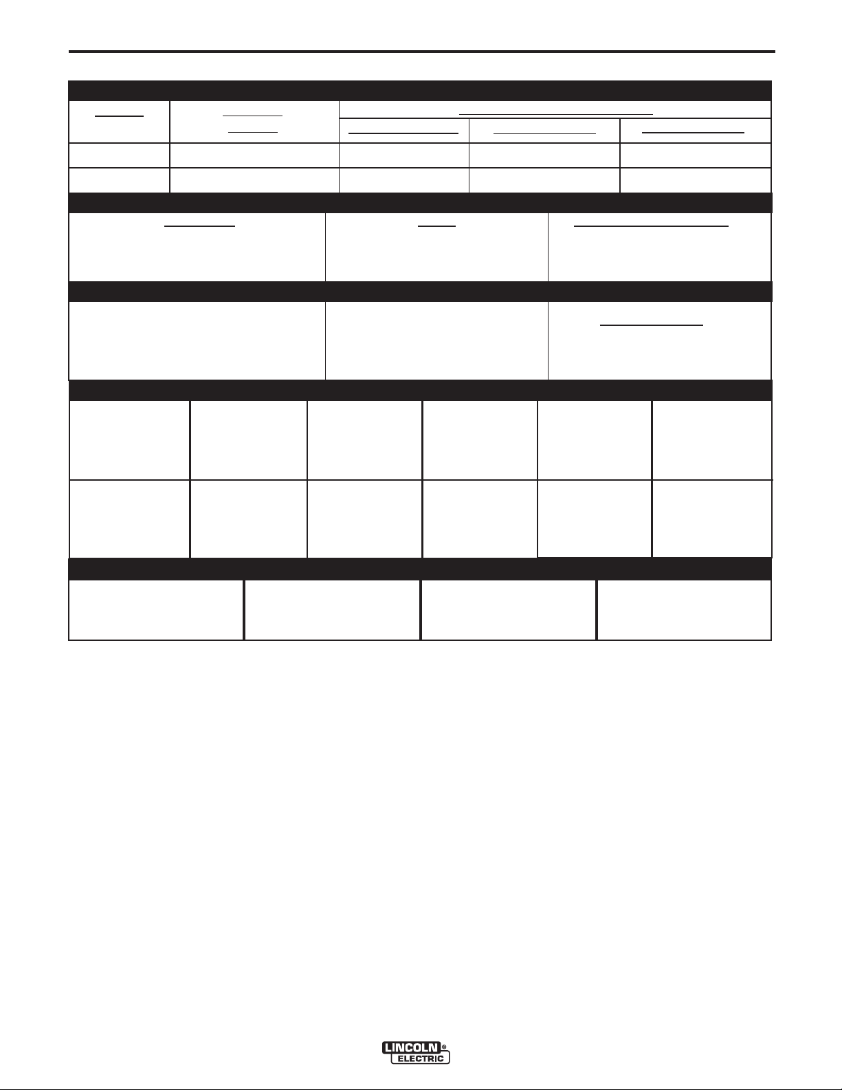
TECHNICAL SPECIFICATIONS – IDEALARC®DC-600 VRD
INPUT - THREE PHASE ONLY
CODES
Standard
Voltage
100% Duty Cycle
Input Current at Rated Output
60% Duty Cycle
A-1
50% Duty Cycle
11613, 11707
11598, 11725
100% Duty Cycle
70A/13V-780A/44V (CV)
90A/24V-780A/44V (CC)
INPUT
VOLTAGE /
FREQUENCY
230
460
575
415
230/460/575/60
415/50/60
Duty Cycle
60% Duty Cycle
50% Duty Cycle
Output Range
RECOMMENDED INPUT WIRE AND FUSE SIZES
HERTZ
50/60
60
60
60
108/54/43
62
RATED OUTPUT
Amps
600
680
750
OUTPUT
Maximum Open Circuit Voltage
5V for 60 HZ models
5V for 50/60 HZ models
INPUT AMPERE
RATING ON
NAMEPLATE
108
54
43
61
TYPE 75°C
COPPER WIRE
IN CONDUIT
AWG(IEC-MM2) SIZES
30°C (86°F) Ambient
2 (34)
6 (14)
8 (8.4)
6 (14)
122/61/49
68
Volts at Rated Amperes
See the OPERATION section
information by model
TYPE 75°C
GROUND WIRE
IN CONDUIT
AWG(IEC-MM2) SIZES
6 (14)
8 (8.4)
8 (8.4)
8 (8.4)
134/67/54
73
44
44
44
Auxiliary Power
for Auxiliary Power
TYPE 75°C
(SUPER LAG)
OR BREAKER
SIZE (AMPS)
175 Amp
90 Amp
70 Amp
100 Amp
1
PHYSICAL DIMENSIONS
HEIGHT
30.75 in
781 mm
1
Also called “inverse time” or “thermal/magnetic” circuit breakers; circuit breakers which have a delay in tripping action that decreases as the magnitude of the current increases.
WIDTH
22.25 in
567 mm
DEPTH
39.0 in
988 mm
WEIGHT
525 lbs.
238 kg.
IDEALARC®DC-600 VRD
Page 10
A-2
INSTALLATION
A-2
SAFETY PRECAUTIONS
Read entire Installation Section before
installing the IDEALARC
®
DC-600 VRD.
ELECTRIC SHOCK CAN KILL.
WARNING
• Only qualified personnel should
install this machine.
• Turn the input power OFF at the
disconnect switch or fuse box
before working on the equipment.
• Do not touch electrically hot parts.
®
• Always connect the IDEALARC
grounding terminal to a good electrical earth
ground.
• Set the IDEALARC®DC-600 VRD Power ON/OFF
PUSH BUTTON to the OFF position when connecting power cord to input power.
DC-600 VRD
__________________
SELECT PROPER LOCATION
Place the welder where clean cooling air can freely
circulate in through the front louvers and out through
the rear louvers. Dirt, dust or any foreign material that
can be drawn into the welder should be kept at a minimum. Failure to observe these precautions can result
in excessive operating temperatures and nuisance
shut-downs.
STACKING
Three IDEALARC®DC-600 VRD machines can be
stacked.
DO NOT stack more than three machines in one
grouping.
DO NOT stack the IDEALARC
another type of machine.
Follow these guidelines when stacking:
1. Select a firm, level surface capable of supporting
the total weight of up to three machines (1570
pounds/712 kilograms).
2. Set the bottom machine in place.
3. Stack the second machine on top of it by aligning
the two holes in the base rails of the second
machine with the two pins on top front of the bottom machine.
4. Repeat process for third machine.
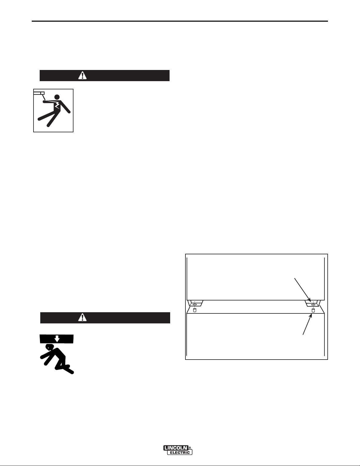
NOTE: The machines must be stacked with the Case
Front of each machine flush with each other. See
Figure A.1.
®
DC-600 VRD on
FIGURE A.1 - Stacking IDEALARC®DC-600
VRD machines
STACKING HOLE
LIMIT ON STACKING
WARNING
• Lift only with equipment of adequate lifting capacity.
• Be sure machine is stable when
lifting.
• Do not lift this machine using lift
bail if it is equipped with a heavy
accessory such as trailer or gas
cylinder.
FALLING • Do not lift machine if lift bail is
EQUIPMENT can damaged.
cause injury. • Do not operate machine while
suspended from lift bail.
• Do not stack more than three high.
• Do not stack the IDEALARC
any other machine.
------------------------------------------------------------------------
®
DC-600 VRD on top of
IDEALARC®DC-600 VRD
STACKING PINS
TILTING
The IDEALARC®DC-600 VRD must be placed on a
stable, level surface so it will not topple over.
Page 11
A-3
INSTALLATION
A-3
ELECTRICAL INPUT CONNECTIONS
Before installing the machine check that the input supply voltage, phase, and frequency are the same as the
voltage, phase, and frequency as specified on the
welder Rating Plate located on the Case Back
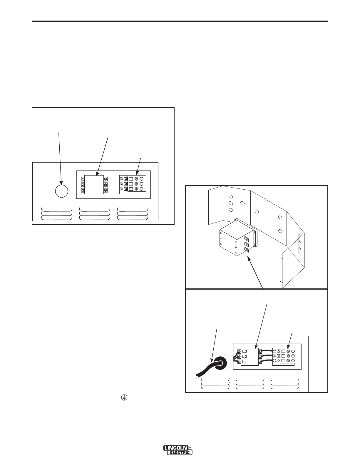
Assembly. Input power supply entry is through the
hole in the Case Back Assembly. See Figure A.2 for
the location of the machineʼs input cable entry opening, Input Contactor (CR1), and reconnect panel
assembly for dual voltage machines.
INPUT SUPPLY
CABLE ENTRY
OPENING
CONTACTOR (CR1)
INPUT
RECONNECT
PANEL ASSEMBLY
INPUT POWER SUPPLY CONNECTIONS
A qualified electrician should connect the input power
supply leads.
1. Follow all national and local electrical codes.
2. Use a three-phase line.
3. Remove Input Access Door at upper rear of
machine.
4. Follow Input Supply Connection Diagram located
on the inside of the door.
5. Connect the three-phase AC power supply leads
L1, L2, and L3 to the input contactor
terminals in the Input Box Assembly by passing
them thru the three aligned .50” diameter holes in
the baffle and tighten them in the terminal connectors. Be sure to close the baffle by inserting the
tab into the slot in the baffle. See Figure A.3.
FIGURE A.2 - Rear Panel
FUSE AND WIRE SIZES
Protect the input circuit with the super lag fuses or
delay type circuit breakers listed on the Technical
Specifications page of this manual for the machine
being used. They are also called inverse time or thermal/magnetic circuit breakers.
DO NOT use fuses or circuit breakers with a lower
amp rating than recommended. This can result in “nuisance” tripping caused by inrush current even when
machine is not being used for welding at high output
currents.
Use input and grounding wire sizes that meet local
electrical codes or see the Technical Specifications
page in this manual.
GROUND CONNECTION
Ground the frame of the machine. A ground
terminal marked with the symbol ( ) is located inside
the Case Back of the machine near the input contactor. Access to the Input Box Assembly is at the upper
rear of the machine. See your local and national electrical codes for proper grounding methods.
INPUT
CONTACTOR (CR1)
INPUT POWER SUPPLY
CABLE WITH BUSHING
OR BOX CONNECTOR
RECONNECT
PANEL ASSEMBLY
FIGURE A.3 - Input Power Supply
Connections
IDEALARC®DC-600 VRD
Page 12
A-4
INSTALLATION
A-4
RECONNECT PROCEDURE
Multiple voltage machines are shipped connected to
the highest input voltage listed on the machineʼs rating
plate. Before installing the machine, check that the
Reconnect Panel in the Input Box Assembly is connected for the proper voltage.
CAUTION
Failure to follow these instructions can cause
immediate failure of components within the
machine.
When powering welder from a generator be sure
to turn off welder first, before generator is shut
down, in order to prevent damage to the welder
------------------------------------------------------------------------
SEE MACHINE RATING PLATE FOR REQUIRED INPUT SUPPLY VOLTAGE
1. TURN OFF THE INPUT POWER USING THE DISCONNECT SWITCH AT THE FUSE BOX
2. CONNECT TERMINAL MARKED TO GROUND PER NATIONAL ELECTRIC CODES.
3. CONNECT THE L1, L2, & L3 INPUT SUPPLY LINES TO INPUT SIDE OF THE CRI CONTACTOR AS SHOWN.
LINES
INPUT
L3
L2
L1
GND
W
V
CONTACTOR
U
CRI
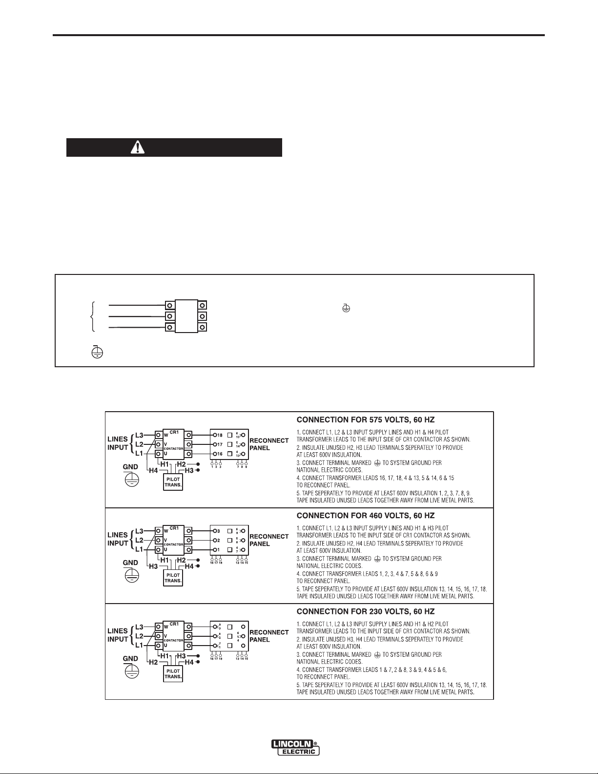
To reconnect a multiple voltage machine to a different
voltage, remove input power and change the position
of the reconnect board on the Reconnect Panel.
Follow The Input Connection Diagram located on the
inside of Case Back Input Access Door. These connection diagrams for the following codes are listed
below.
1. For 415 Single Voltage, see Figure A.4. (S17894)
2. For 230/460/575, see Figure A.5. (M15666)
FIGURE A.4-Reconnect Panel Board Positions for Single Voltage Machines
FIGURE A.5-Reconnect Panel Board Positions for 230/460/575 VAC Machines
IDEALARC®DC-600 VRD
Page 13
A-5
INSTALLATION
A-5
OUTPUT CONNECTIONS
See Table A.1 for recommended IDEALARC®DC-600 VRD cable sizes for combined lengths of electrode and
work cables.
TABLE A.1
IDEALARC®DC-600 VRD Cable Sizes for Combined Lengths of Copper Electrode and Work
Cable at 100% Duty Cycle
Cable SizeParallel CablesCable Length
2
Lengths up to 150 ft. (46m)
ELECTRODE, WORK AND #21 LEAD
CONNECTIONS
1/0 (53mm
2
2
2/0 (67mm
3/0 (85mm
)2
2
)150 ft.(46m) to 200 ft (61m)
2
)200 ft.(61m) to 250 ft.(76m)
A. Connect Electrode and Work Leads to
Output Terminals.
1. Set the ON/OFF toggle switch to OFF.
2. Locate the retractable strain relief loops directly
below the output terminals in the lower right and
lower left corners of the Case Front Assembly.
See Figure A.6.
3. Pull out the retractable strain relief loops.
4. Insert the electrode lead through the loop directly
below the desired polarity (positive or negative).
Pull through enough cable to reach the output
terminals.
5. Connect electrode lead to the desired terminal
(positive/negative).
6. Tighten the output terminal nut with a wrench.
7. Connect the work lead to the other output
terminal following steps 4-6.
FIGURE A.6 - Output Terminals.
B. Connect #21 Work Sense Lead to Proper
Terminal
There are two work sense lead connection points (+21
and -21) on terminal strip (T.S.2) located behind the
hinged access panel on the right side of the case
front. See 14 Pin MS Type Receptacle section or
Terminal Strip Section for connection procedure.
IDEALARC®DC-600 VRD
Page 14

A-6
K=42
K=42
INSTALLATION
AUXILIARY POWER AND CONTROL CONNECTIONS
Located at the left side of the front of the welder
behind a hinged cover is a 115VAC duplex receptacle
for auxiliary power (60 Hertz Models only). On the right
side of the case front is a 14 Pin MS type receptacle
for connection of auxiliary equipment such as wire
feeders. Also, terminal strips with 115VAC and connections for auxiliary equipment are located behind the
hinged access panel on the right side of the case front.
(see Auxiliary Power Table for details)
AUXILIARY POWER TABLE
Voltage and Circuit Breaker Ratings at Auxiliary Power
Connections for Various Models
Table for Codes 11598, 11613
Auxiliary 60 Hz 50/60 Hz
Power Models Models
Connections
At Duplex 15A No Duplex
Receptacle 115V
Terminal strip 115V 15A 115V 15A
terminals 31 & 32
MS-Receptacle 115V 15A 115V 15A
pins A & J
MS-Receptacle 42V 10A 42V 10A
pins I & K
115VAC DUPLEX RECEPTACLE (60 HERTZ
MODELS ONLY)
Table for Codes 11707, 11725
Auxiliary 60 Hz 50/60 Hz
Power Models Models
Connections
At Duplex 15A No Duplex
Receptacle 115V
Terminal strip 115V 15A 115V 15A
terminals 31 & 32
MS-Receptacle 42V 10A 42V 10A
pins I & K
A-6
PIN LEAD NO. FUNCTION
A 32 115 VAC
B GND Chassis Connection
C 2 Trigger Circuit
D 4 Trigger Circuit
E 77 Output Control
F 76 Output Control
G 75 Output Control
H 21 Work Sense
I 41 42 VAC
J 31 115 VAC
K 42 42 VAC
L --- --M --- --N --- ---
TERMINAL STRIPS
Terminal strips are available behind the cover on the
case front to connect wire feeder control cables that
do not have a 14 Pin MS-type connector. These terminals supply the connections as shown in the following
Terminal Strip charts. NOTE: There are two work
sense lead connection points on the terminal strip.
Connect both the work sense lead #21 from the 14 pin
connector and #21 lead of the control cable to “-21”
when welding positive polarity or to “+21” when welding negative polarity.
(3)
Connection
(3)
(2)
The 115VAC duplex receptacle is protected by a 15
Amp circuit breaker located on the nameplate. The
receptacle is a NEMA 5-15R.
14 PIN MS TYPE RECEPTACLE
(For MS3106A-20-27PX Plug. L.E.C. Part #S12020-32)
Refer to the Figure A.7 for the available circuits in the
14 pin receptacle.
42 VAC is available at receptacle pins I and K.
A 10 amp circuit breaker protects this circuit.
On codes 11598 and 11613, 115 VAC is available at
receptacle pins A and J. A 15 amp circuit breaker protects this circuit. (See Figure A.7 for pin allocation).
Note that the 42 VAC and 115 VAC circuits are electrically isolated from each other.
FIGURE A.7
FRONT VIEW OF 14-PIN CONNECTOR RECEPTACLE
Pin location for Codes 11598, 11613
A=32
B=GND
L N
C=2
D=4
E=77
J=31
I=41
G=75
F=76
M
Pin location for Codes 11707, 11725
B=GND
LN
C=2
H=21
D=4
E=77
M
I=41
G=75
F=76
IDEALARC®DC-600 VRD
H=21
TERMINAL STRIP 1 (T.S.1)
Lead No. Function
75 Output Control
76 Output Control
77 Output Control
TERMINAL STRIP 2 (T.S.2)
Lead No. Function
+21
-21
41 42 VAC
4 Trigger Circuit
2 Trigger Circuit
31 115 VAC
32 115 VAC
(1)
115VAC circuit is on all models.
(2)
As shipped from the factory Lead #21 from the 14 Pin connector
is connected to “-21” on the terminal strip (T.S.2). This is the configuration for positive welding. If welding negative polarity, connect lead #21 to the “+21” connection point on the terminal strip
(T.S.2).
(3)
115VAC is not available at the 14 Pin connector on Codes 11707,
11725.
Work Connection (Electrode Negative)
Work Connection (Electrode Positive)
(1)
(1)
(2)
Page 15
B-1
OPERATION
SAFETY PRECAUTIONS
Read this entire section of operating instructions
before operating the machine.
WARNING
ELECTRIC SHOCK can kill.
• Do not touch electrically live parts or
electrodes with your skin or wet
clothing.
• Insulate yourself from the work and
ground.
• Always wear dry insulating gloves.
• Do not use AC welder if your clothing, gloves or work area is damp or
if working on, under or inside workpiece.
Use the following equipment:
-Semiautomatic DC constant voltage (wire) welder.
-DC manual (stick) welder.
-AC welder with reduced voltage control.
• Do not operate with panels removed.
• Disconnect input power before servicing.
------------------------------------------------------------------------
READ THIS WARNING, PROTECT
YOURSELF & OTHERS.
B-1
FUMES AND GASES can be
dangerous.
• Keep your head out of fumes.
• Use ventilation or exhaust at the arc, or both, to
keep fumes and gases from your breathing zone
and general area.
WELDING, CUTTING and GOUGING SPARKS can cause fire or
explosion.
• Do not weld near flammable material.
• Do not weld, cut or gouge on containers which have held flammable material.
ARC RAYS can burn.
• Wear eye, ear, and body protection.
Observe additional Safety Guidelines
detailed in the beginning of this manual.
------------------------------------------------------------------------
IDEALARC®DC-600 VRD
Page 16

B-2
GENERAL DESCRIPTION
The IDEALARC®DC-600 VRD includes a proprietary design which is
available in certain arc welding power sources such as the DC 600
and 400. This internal circuitry applies a high frequency, low voltage
signal through the Electrode and Work terminals, while disabling the
output of the power source. The OCV ( open circuit voltage) during
this period is less than 2 Volts RMS at 70kHz. When an Electrode to
Work load of 100 ohms or less is applied, the output of the power
source is enabled, allowing normal welding operation. When the output load is removed, within 0.3 seconds, the output is again disabled
reducing the OCV to less than 2 Volts RMS
®
The IDEALARC
welding and cutting power source. It uses a single range potentiometer to control:
• Submerged Arc Semi-Automatic or Automatic Welding
• Open Arc Semi-Automatic or Automatic Welding
• Stick Welding
• Air/Carbon Arc Cutting (Carbon Rod Sizes up to 3/8” Diameter)
The IDEALARC®DC-600 VRD has a three-position Welding Mode
Switch to enable the user to operate in one of three modes:
• Constant Current (CC) Stick also used for Air Carbon Arc Cutting
Process (AAC)
• Constant Voltage (CV) Submerged Arc
• Constant Voltage (CV) Innershield (also used for FCAW/GMAW)
Two VRD models are available:
• Domestic - 230/460/575V 60 Hertz model
• Export-415V 50/60 Hertz model
The optional Multi-Process Switch allows the user to switch between
semi-automatic or automatic welding and stick welding or air/carbon
arc cutting without disconnecting the wire feeder equipment control,
electrode, and work leads.
DC-600 VRD is an SCR controlled three phase
RECOMMENDED PROCESSES AND EQUIPMENT
The IDEALARC®DC-600 VRD is designed for GMAW (MIG), FCAW,
and submerged arc (SAW) within the capacity of the machine. It can
also be used for stick welding (SMAW) and for air carbon arc (AAC)
cutting with carbon rods up to 3/8" diameter.
The IDEALARC®DC-600 VRD is provided with a three position mode
switch that selects CV Innershield, CV Submerged Arc, or CC Stick.
®
The IDEALARC
ing equipment, including:
• Semi-automatic wire feeders LN-7*, LN-7 GMA*, LN-742, LN-8*,
LN-9*, LN-9 GMA*, LN- 10, LN-15 LN-23P, LN-25, and DH-10.
• Automatic wire feeders NA-3*, NA-5*, and NA-5R*.
• Tractors LT-56* and LT-7*
*The 14-pin MS receptacle on codes 11707 and 11725 does not provide
115VAC for these feeders; 115VAC must be obtained from terminal
strip.
DC-600 VRD can be easily connected to wire feed-
OPERATION
• No large output mechanical contactors or Solid State switches such
as SCRʼs, etc; are added to the Electrode to Work output circuit.
• “Tamper Resistant” design. Circuitry is built into power source, not
an exterior package which could easily be tampered with.
• No reduction of power source output rating. This feature does not
affect the rating of the power source.
• Self diagnostics upon machine power up. Indicator lights are tested.
• Green lamp on when weld voltage is less than 30 volts. If weld voltage exceeds 30 volts, Green lamp turns off and Red lamp turns on.
• Output is disabled if OCV > 50 volts is sensed.
• Excellent arc characteristics for optimum constant voltage submerged arc and Innershield welding performance.
• A control circuit designed to provide good starting for a large variety
of processes and procedures.
• Output Control Potentiometer that provides easy single range continuous control.
• Output Control Switch that provides simple switching from local to
remote control.
• Output Terminals Switch to energize output terminals either local or
remote.
• White neon pilot light to confirm that the Input Contactor is energized.
• DC Ammeter and Voltmeter
• 42VAC 10 Amp auxiliary power available for the wire feeder, circuit
breaker protected.
• Single MS-type (14 pin) connector for wire feeder.
• 115VAC 15 Amp auxiliary power available for the wire feeder, circuit
breaker protected.
• 115VAC 15 Amp duplex plug receptacle available on 60 Hertz models, circuit breaker protected.
• Multi-functional terminal strip for easy connection of wire feeding
control cables.
• Recessed, output terminals to avoid any person or object from accidentally coming into contact with the output terminals and labeled "
+ " and " - " for easy identification.
• Thermostatically protected power source.
• Electronic protection circuit to protect power source against overloads.
• Input line voltage compensation to provide an essentially constant
output.
• SCR electronically controlled welder output provides extra long life,
especially for highly repetitive welding applications.
• Solid state 2 and 4 circuit for extra long life.
• Two circuit solid state control system provides maximum performance and circuit protection.
• Low profile case provides maximum use of space.
• Convenient access to all controls.
• Output lead strain relief loops to prevent terminal and cable damage.
• Easily removed case side, even when stacked.
• Outdoor operation because enclosure is designed with air intake
louvers that keep dripping water from entering the unit. Transformer,
SCR Bridge and choke have special corrosion resistant paint for
added protection.
DESIGN FEATURES AND ADVANTAGES
B-2
IDEALARC®DC-600 VRD
Page 17

B-3
OPERATION
B-3
WELDING CAPABILITY
The IDEALARC®DC-600 VRD has the following Output and Duty Cycle based on operation for a 10 minute period:
600 Amps, 44 Volts at 100%
680 Amps, 44 Volts at 60%
750 Amps, 44 Volts at 50%
MEANINGS OF GRAPHICAL SYMBOLS ON CASE FRONT
Input POWER ON/OFF Switch
SYMBOL
MEANING
INPUT POWER
Pilot Light
Input power on when light is illuminated
(except for abnormal conditions).
Indicates main Transformer is operating.
OUTPUT CONTROL
ON
OFF
LOCAL/REMOTE Switch
SYMBOL
Control Of Output Voltage and
Current is Via IDEALARC®DC-600
VRD's Control Dial
Remote Control of Output Voltage
MODE Switch
CC STICK: Shielded Metal Arc
Welding (SMAW), this switch
position is also used for Air
Carbon Arc Cutting (AAC)
CV SUBMERGED ARC:
Constant Voltage Submerged
Arc Welding (SAW)
CV INNERSHIELD: Flux Cored
Arc Welding (FCAW), this switch
position is also used for Gas
Metal Arc Welding (GMAW).
MEANING
and Current
OUTPUT VOLTAGE
AND CURRENT
Clockwise Increase of Output
Voltage and Current
TERMINALS ON/REMOTE Switch
OUTPUT TERMINALS
ENERGIZED
Remote Control of Output Terminals
(Energized or Non-Energized)
Output Terminal Connections
Positive Output Terminal
Negative Output Terminal
WARNING Identification
Warning Identification
Circuit Breaker
Circuit Breaker (two breakers: 15A for
115V circuit and 10A for 42V circuit)
Thermal Protection Light
On when power source exceeds nor-
mal operating temperature.
IDEALARC®DC-600 VRD
Page 18

B-4
OPERATION
B-4
MEANING OF GRAPHICAL
SYMBOLS ON RATING PLATE
(LOCATED ON CASE BACK)
Designates welder complies with
National Electrical Manufacturers
NEMA EW 1 (100%)
Association requirements EW 1
Class I with 100% duty cycle at
600Amps output.
Three Phase Input Power
3 Phase transformer with rectified
DC output
Line Connection
Gas Metal Arc Welding (GMAW)
MEANING OF GRAPHICAL
SYMBOL FOR GROUND CONNECTION
Signifies the equipment connection
point for the protective earth ground
CONTROLS AND SETTINGS
All operator controls and adjustments are located on
the Case Front Assembly of the IDEALARC
VRD. See Figure B.1 for the location of each control.
5
3
6
8
14
5
6
4
7
7
3
2
1
8
9
10
DC-600 VRD
9
®
DC-600
15
4
1
2
NRTL/C
Flux Cored Arc Welding (FCAW)
Shielded Metal Arc Welding (SMAW)
Submerged Arc Welding (SAW)
Designates welder complies with
both Underwriters Laboratories (UL)
standards and Canadian Standards
Association (CSA) standards. (60
Hertz Models)
11
10
12
13
FIGURE B.1 - CONTROL PANEL KEYS
1. Input POWER ON/OFF Switch
This toggle switch turns the machine on or off.
Putting the switch in the ON “ ” position energizes the machineʼs input contactor applying input
power to the machine. Switching the switch to the
OFF “ ” position de-energizes the input contactor.
2. POWER Light
When the POWER switch is in the ON position the
machineʼs white POWER light will illuminate. If the
input contactor de-energizes the machine in an
abnormal situation the pilot light will turn off. In this
situation it may be necessary to reset the machine
by switching the POWER switch to the OFF and
then to the ON position. (See Overload,
Overcurrent, and Fault Protection Section)
IDEALARC®DC-600 VRD
Page 19

B-5
3. OUTPUT CONTROL
This control provides continuous control of the
machineʼs output voltage and current from minimum to maximum (typical full pot range between
15 to 44 volts and 90 to 750 amps) as it is rotated
clock-wise. Voltage or current control is determined by setting of Mode Switch (CV or CC).
OPERATION
11. Terminal Strip Cover Panel
Rotate this panel to gain access to the circuits
made available at the two terminal strips (T.S.1
and T.S.2). These terminal strips contains the
same circuits as the 14 pin MS-receptacle. There
is a box connector adjacent to this cover for routing leads to the terminal strips.
B-5
4. OUTPUT TERMINALS ON/REMOTE Switch
When this switch is in the REMOTE “ ” position, the IDEALARC®DC-600 VRDʼs output terminals will be electrically “cold” until a remote device
such as a wire feeder closes the #2 and #4 circuit
in the MS-receptacle or terminal strip (T.S.2).
When this switch is in the ON “ ” position the
machineʼs output terminals will be electrically
energized all the time.
5. LOCAL/REMOTE Switch
When this switch is set to the LOCAL “ “ position, control of the output voltage and current is via
the OUTPUT CONTROL on the IDEALARC
600 VRDʼs control panel. When this switch is set
to the REMOTE “ ” position, control is
through a remote source such as a wire feeder via
the #75, #76, and #77 leads in the MS-receptacle
or terminal strip (T.S.1).
6. Mode Switch
This switch allows for selecting the welding
process to be used:
CC STICK-for SMAW and AAC
CV SUBMERGED ARC- for SAW
CV INNERSHIELD- for FCAW and GMAW
7. 115VAC Duplex Receptacle (60 Hertz Models)
This receptacle provides up to 15 amps of 115
VAC auxiliary power.
8. 115VAC 15 Amp Circuit Breaker
This breaker protects the 115 VAC auxiliary circuits located in the duplex receptacle, terminal
strip (T.S.2) and MS-receptacle.
9. 42VAC 10 Amp Circuit Breaker
This breaker protects the 42VAC auxiliary circuits
located in the terminal strip (T.S.2) and MS-receptacle.
10. 14 Pin MS-Receptacle
This connector provides easy connection for a
wire feeder control cable. It provides connections
for auxiliary power, output switching, remote output control, wire feeder voltmeter sense lead and
ground. Refer to 14 Pin MS Type Receptacle in
the Installation Section for information about the
circuits made available at this receptacle.
®
DC-
12. Negative Output Terminal
This output terminal is for connecting a welding
cable. To change welding polarity and for proper
welding cable size refer to Electrode and Work
Cables in the Installation Section.
13. Positive Output Terminal
This output terminal is for connecting a welding
cable. To change welding polarity and for proper
welding cable size refer to Electrode and Work
Cables in the Installation Section.
14. VRD Lights
When VRD is active, in CC mode, these lights
illuminate based on the stud voltage while welding. The green light will be on when the welding
voltage is under 30 volts and the red light light will
turn on when the voltage is 30 volts or greater.
15. Thermal Protection Light (Only on Codes
11707 and 11725)
An amber light on the machine control panel indicates when either of the two protective thermostats has opened. Output power will be disabled temporarily. Thermostat will automatically
reset when the machine cools to an acceptable
operating temperature.
AUXILIARY POWER IN MS-RECEPTACLE
42 volt AC auxiliary power, as required for some wire
feeders, is available through the wire feeder MSreceptacle. A 10 amp circuit breaker protects the 42
volt circuit from overloads.
On Codes 11598 and 11613, IDEALARC®DC-600
VRD machines supply 115 volt AC auxiliary power
through the wire feeder receptacle. A 15 amp circuit
breaker protects the 115 volt circuit from overloads.
IDEALARC®DC-600 VRD
Page 20

B-6
OPERATION
OVERLOAD, OVERCURRENT, AND
FAULT PROTECTION
This welder has thermostatic protection from excessive duty cycles, overloads, loss of cooling, and high
ambient temperatures. When the welder is subjected
to an overload or loss of cooling, a thermostat will
open. The input contactor will open and remain open
until the machine cools; the white POWER light stays
illuminated. No welding is possible during this cool
down period. The machine will reset automatically
when the thermostat cools.
The power source is also protected against overcurrents in the SCR bridge assembly through an electronic protection circuit. This circuit senses currents
over 780 amps on the power source and opens the
input contactor should the overcurrent remain for a
predetermined time (the white POWER light also turns
off).
The predetermined time varies with the amount of
overcurrent; the greater the overcurrent, the shorter
the time. The input contactor will remain open until
the power source is manually started by resetting the
POWER ON/OFF toggle switch.
For codes 11707 and above.
The power source is protected against overvoltage
when not welding in CC mode. If the protection circuit
senses voltage in excess of 49V at the studs when no
welding is taking place, the POWER light will turn off.
The input contactor will open up and remain open until
the power source is manually restarted by toggling the
ON/OFF switch.
The power source circuitry is protected from faults on
leads 75, 76, or 77. If any of these leads are connected to either the positive or negative output leads, the
IDEALARC
pletely (input contactor opens and white POWER light
turns off), or will operate at minimum output thus preventing any damage to the IDEALARC®DC-600 VRD.
If IDEALARC®DC-600 VRD shuts down, it must be
manually started by resetting the POWER ON/OFF
toggle switch.
®
DC-600 VRD will either shut down com-
VRD (VOLTAGE REDUCTION
DEVICE) OPERATION
B-6
Whenever the CC welding mode is selected and
power is turned on, or power is on and the welding
mode is changed from Constant Voltage (CV) to
Constant Current (CC), the VRD circuitry performs a
self test for approximately five seconds. For one second the input contactor and the cooling fan will turn
on, then off. With welding inhibited, the studs will be
examined. Both VRD lights will be on to indicate that
the machine is in self test mode.
After passing the self test, only the green light remains
on and the machine is ready to weld. If the test fails,
both lights will remain on and welding remains inhibited. This could be caused by the stick electrode holder being shorted to work, or if an across the arc wire
feeder, such as the LN 25, is connected to the power
source.
To use a system with sense leads in CC mode on a
VRD model, disconnect the feederʼs work sense lead
prior to the self test. After passing the self test, reconnect the work sense lead.
• In CC mode, the VRD will reduce the output voltage
regardless of the position of the “TERMINALS
ON/REMOTE” Switch.
• The voltmeter will display zero volts until the electrode contacts the work and establishes the welding
arc.
LED STATUS
RED
ON
ON
OFF
OFF
NOTE:
Under normal circumstances, the machine will never
be able to exceed 49 volts while not welding. If,
under abnormal circumstances, the output voltage
were to exceed 49 volts while not welding, the VRD
turns the output off. The green light would be on
because the voltage would be zero and the pilot light
will be off, but establishing an arc would not be possible. The machineʼs “POWER ON/OFF” Switch
must be cycled off, then back on, to restore normal
operation.
GREEN
ON
OFF
ON
OFF
Power source is in self test mode.
Output voltage is greater than 30 V.
Output voltage is less than 30 V.
Power source is in CV mode.
LED STATUS
The VRD electronic circuitry is designed to reduce the
OCV of the power source in the Constant Current
(CC) Stick welding mode only. The operation of the
machine with the VRD is slightly different than the
operation of a standard machine. The following
describes the machine operation with the VRD
installed in the DC600.
IDEALARC®DC-600 VRD
Page 21

B-7
The Lincoln VRD circuit meets the requirements of
AS1674.2-2007, Safety in welding and allied
processes - Electrical, for Category C environments.
Category C environments include coffer dams,
trenches, mines, in rain, etc.
The Lincoln VRD circuit also meets recommendation
of ANSI Z49.1- 2005, Safety in Welding, Cutting and
Allied Processes, for use in electrically hazardous
conditions ( in damp locations or while wearing wet
clothing; on metal structures such as floors, gratings
or scaffolds; when in cramped positions such as sitting, kneeling or lying, if there is a high risk of
unavoidable or accidental contact with the workpiece
or ground ).
OPERATION
OPERATING STEPS
The following procedures are for using the IDEALARC®DC-600 VRD in the local control mode of
operation. For remote control of the machine, see the
Remote Control of Machine Operation section.
B-7
3. Set the Welding Mode switch to welding process
being used:
• CC STICK (for SMAW and AAC)
4. Turn the POWER ON/OFF Toggle Switch to the
“ON” position:
• The white pilot light glows and the fan starts for 1
second.
• The machine continues the 5 second pretest indicated by both red and green VRD lights glowing.
When the red light turns off, the pilot light turns on
and the fan restarts, the machine is ready.
5. Set OUTPUT CONTROL Potentiometer to desired
current.
6. Set the OUTPUT TERMINALS switch to either
“ON” ( output terminals active) or “REMOTE” (output terminals active when #2 and #4 is closed by
remote device such as wire feeder).
7. Make the weld.
REMOTE CONTROL OF MACHINE
OPERATION
Before operating the machine, make sure you have all
materials needed to complete the job. Be sure you
are familiar with and have taken all possible safety
precautions before starting work. It is important that
you follow these operating steps each time you use
the machine.
CV MODE
1. Connect the #21 work lead to either + or - on terminal strip (T.S.2).
2. Turn on the main AC power supply to the machine.
3. Set the Welding Mode switch to welding process
being used:
• CV SUBMERGED ARC (for SAW)
• CV INNERSHIELD (for FCAW and GMAW)
4. Turn the POWER ON/OFF Toggle Switch to the
“ON” position:
• The white pilot light glows and the fan starts.
5. Set OUTPUT CONTROL Potentiometer to desired
voltage.
6. Set the OUTPUT TERMINALS switch to either
“ON” ( output terminals energized) or “REMOTE”
(output terminals energized when #2 and #4 closed
by remote device such as wire feeder)
7. Make the weld.
The toggle switch on the control panel labeled
“Remote - Panel” gives the operator the option of controlling the machine output from a remote location. If
in the Remote position a wire feeder with remote control capabilities or a remote control device such as a
K775 must be connected to terminals 75, 76, and 77.
Refer to Accessories Section for wire feeder remote
information.
WELDING PROCEDURE
RECOMMENDATIONS
Select Welding Mode Switch position based on type of
welding to be done.
1. Innershield Welding (FCAW)/MIG (GMAW)
Welding: Use the CV INNERSHIELD mode.
2. Submerged Arc Welding (SAW): Use the CV
SUBMERGED ARC mode. If performing high
speed welding, switch between the CV
Submerged Arc and the CV Innershield mode and
use the mode that produces the best welding
results.
CC MODE
1. Connect the #21 work lead to either + or - on terminal strip (T.S.2).
2. Turn on the main AC power supply to the machine.
IDEALARC®DC-600 VRD
Page 22

B-8
3. Air/Carbon Arc Cutting (AAC) / Stick Welding
(SMAW) / High Current, Large Puddle Submerged
Arc Welding (SAW): Use the CC STICK mode.
When the IDEALARC®DC-600 VRD is used for
Air/Carbon Arc cutting, the OUTPUT CONTROL
potentiometer should be set to "9" initially. Based
on the size of the carbon being used or the
process, turn the potentiometer to a lower setting
as required by the process. You can use carbon
rods up to 3/8" in diameter at currents as high as
750 amps with excellent arc control. The welder
protection circuit protects the machine from
extremely high short circuiting pulses.
OPERATION
B-8
5. Follow the following guidelines for good arc striking
detailed below for each welding mode.
GOOD ARC STRIKING GUIDELINES FOR THE NA-3
WITH THE IDEALARC®DC-600 VRD IN THE CV
INNERSHIELD, CV SUBMERGED ARC OR CC STICK
WELDING MODES.
Following are some basic arc striking techniques that
apply to all wire feed processes. Using these procedures
should provide trouble-free starting. These procedures
apply to single, solid wires and Innershield wires.
1. Cut the electrode to a sharp point.
SEMI-AUTOMATIC AND
AUTOMATIC WIRE FEEDING WITH
THE IDEALARC®DC-600 VRD AND
WIRE FEEDERS
When using the IDEALARC®DC-600 VRD with semiautomatic or automatic wire feeding equipment and
for stick welding or air/carbon arc cutting, it is recommended that the optional MULTI-PROCESS SWITCH
be used. This switch permits you to easily change the
polarity of the connected wire feeding equipment or
switch to stick welding or air/carbon arc cutting.
To use a feeder with sense leads in CC mode on the
IDEALARC®DC-600 VRD, disconnect the feederʼs
work sense lead prior to the VRD self test. Reconnect
the work sense lead after passing the self test.
NA-3 AUTOMATIC WIRE FEEDER
1. Set the IDEALARC®DC-600 VRD LOCAL/REMOTE
Switch to REMOTE. Set the OUTPUT TERMINALS
switch to REMOTE. NOTE: Later model NA-3 automatic wire feeders are capable of cold starts when
the NA-3 Mode switch is in the CV or CC mode position and when welding in positive polarity only. Some
earlier models are capable of cold starting only in the
CC mode position. Cold starting enables you to inch
the wire down to the work, automatically stop, and
automatically energize the flux hopper valve.
2. Set the IDEALARC®DC-600 VRD welding mode
switch for the desired process: CV SUBMERGED
ARC, CV INNERSHIELD mode or CC STICK mode.
2. Set the NA-3 Open Circuit Voltage Control to the
same dial setting as the Arc Voltage Control. If this is
a new welding procedure, a good starting point is to
set the Open Circuit Voltage Control to # 6.
NOTE: The open circuit voltage of the
IDEALARC
16 volts to 56 volts in the CV INNERSHIELD or CV
SUBMERGED ARC modes. The open circuit voltage
is essentially zero in the CC STICK mode.
3. Run a test weld. Set proper current, voltage, and
travel speed.
• For the best starting performance, the NA-3 Open
Circuit Voltage Control and Voltage Control setting
should be the same. Set the Inch Speed Control for
the slowest inch speed possible.
• To adjust the Open Circuit Voltage Control to get the
best starting performance, make repeated starts
observing the NA-3 voltmeter.
When the voltmeter pointer swings smoothly up to
the desired arc voltage, without undershooting or
overshooting the desired arc voltage, the Open
Circuit Voltage Control is set properly.
If the voltmeter pointer overshoots the desired voltage and then returns back to the desired voltage, the
Open Circuit Voltage Control is set too high. This
can result in a bad start where the wire tends to
"Blast off."
If the voltmeter pointer hesitates before coming up to
the desired voltage, the Open Circuit Voltage Control
is set too low.This can cause the electrode to stub.
4. Start and make the weld.
®
DC-600 VRD varies from approximately
3. Set the NA-3 mode Switch Position to either CV or
CC to match the IDEALARC®DC-600 VRD mode
selected in step 2.
4. Refer to the NA-3 operators manual for instructions
on how to use the NA-3 in conjunction with the IDEALARC®DC-600 VRD.
IDEALARC®DC-600 VRD
• Cold starts. For cold starts, be sure the work piece is
clean and the electrode makes positive contact with
the work piece.
• Hot "On the Fly" starts. For hot starts, travel should
begin before the wire contacts the work piece.
Page 23

B-9
ARC STRIKING WITH IDEALARC®DC-600 VRD AND
THE NA-3 START BOARD
When electrical strikeouts exceed 1 3/4” (44.4mm) an
NA-3 Start Board may be required to improve arc striking.
When the NA-3 Start Board is used to improve arc striking, use the following procedures:
1. Set start time at 0.
2. Set NA-3 start current and start voltage at midrange.
OPERATION
B-9
If the voltmeter pointer hesitates before coming
up to the desired voltage, the Open Circuit
Voltage Control is set too low. This can cause the
electrode to stub.
• Set NA-3 Start Board current and voltage as
close to the welding procedure current and voltage as possible.
NOTE: The Start Board current and voltage
should be as close as possible to the welding procedure current and voltage, while still getting satisfactory starts.
3. Set the NA-3 output current and voltage to the proper settings for the welding procedure to be used.
4. Turn the Start Board Timer to maximum.
5. Set Start Board current and voltage control.
• Set the Start Board current control to 1 1/2 dial numbers below that set on the NA-3 current control.
• Set the Start Board voltage control equal with the
NA-3 voltage control setting.
NOTE: These Start Board current and voltage settings result in a start up current that is lower than
the NA-3 current setting and approximately equal
with the NA-3 voltage setting for the desired welding procedure.
6. Establish the correct arc striking procedure with
the NA-3 Start Board timer set at maximum.
• For the best starting performance, the NA-3 Open
Circuit Voltage Control and Voltage Control setting should be the same. Set the Inch Speed
Control for the slowest inch speed possible.
• Set the start time to as low a time as possible
while still getting satisfactory starts.
7. Start and make the weld.
IDEALARC®DC-600 VRD POWER
SOURCE SETTING WHEN CONNECTED
TO NA-5 WIRE FEEDER
When using the IDEALARC®DC-600 VRD with the
NA-5 wire feeder, set the controls on the IDEALARC
DC-600 VRD as follows for the best performance:
1. Turn OFF main AC input power supply to the IDEALARC®DC-600 VRD.
2. Connect the electrode cables to terminal polarity
to be used. NOTE: Cold starting is only availiable
in positive polarity.
3. Connect the #21 work lead (on T.S.2) to the
same polarity as the work cable connection.
4. Set the IDEALARC®DC-600 VRD
LOCAL/REMOTE Switch to REMOTE.
®
• To adjust the Open Circuit Voltage Control to get
the best starting performance, make repeated
starts observing the NA-3 voltmeter.
When the voltmeter pointer swings smoothly up to
the desired arc voltage, without undershooting or
overshooting the desired arc voltage, the Open
Circuit Voltage Control is set properly.
If the voltmeter pointer overshoots the desired
voltage and then returns back to the desired voltage, the Open Circuit Voltage Control is set too
high. This can result in a bad start where the wire
tends to "Blast off."
IDEALARC®DC-600 VRD
5. Set the IDEALARC®DC-600 VRD OUTPUT TERMINALS switch to REMOTE.
®
6. Set the IDEALARC
MODE SWITCH to the position that matches the
welding process being used.
• For submerged arc welding, set WELDING
MODE SWITCH to CV SUBMERGED ARC position.
• For all open arc welding processes set WELDING
MODE SWITCH to CV INNERSHIELD position.
DC-600 VRD WELDING
Page 24

C-1
ACCESSORIES
WIRE FEEDERS AND TRACTORS
C-1
Undercarriages (K817P, K842)
The IDEALARC®DC-600 VRD can be used to power
any of the following Lincoln Wire Feeders and
Tractors:
For easy moving of the machine, optional undercarriages are available with polyolefin wheels (K817P) or
a platform undercarriage (K842) with mountings for
two gas cylinders at rear of welder.
Semi-Automatic Wire Feeders:
DH-10 LN-9
LN-7* LN-9 GMA*
LN-7 GMA* LN-23P
LN-742 LN-25
*
FACTORY OR FIELD INSTALLED
OPTIONS
LN-8* LN-10
Multi-Process Switch (K804-1)
Automatic Wire Feeders*:
NA-3 NA-5R
NA-5
The MULTI-PROCESS SWITCH gives you the ability
to:
• Switch between "stick welding or air/carbon arc cut-
Tractors*:
LT-7 LT-56
ting" and using a semi-automatic or automatic wire
feeder.
• Change the polarity of a semi-automatic or automatic wire feeder without changing any electrical
*
Codes 11707 and 11725 only provide 115VAC for these feeders at the terminal strip.
cable connections.
See Figure C.1
FIELD INSTALLED OPTIONS
FIGURE C.1 - MULTI-PROCESS SWITCH
Remote Output Control (K775 or K857
with K864 Adapter)
An optional “remote out control” is available. The
K775 is the same remote control that is used on other
Lincoln power sources. The K775 consist of a control
box with 28 feet (8.5mm) of four conductor cable. This
connects to terminals 75,76, and 77 on the terminal
strip (T.S.1) and the case grounding screw so marked
with the symbol “ ” on the machine. These terminals are located behind the hinged cover on the case
front. This control will give the same control as the
output control on the machine.
The K857 is similar to the K775, except the K857 has
a 6-pin MS-style connector. The K857 requires a
K864 adapter cable which connects to the 14-pin connector on the case front.
Remote Control Adapter Cable (K864)
STRAIGHT PLUG (14 PIN)
TO POWER SOURCE
A "V" cable 12" (.30 m) long to connect a K857
Remote Control (6-pin connector) with an LN-7 wirefeeder (14-pin connector) and the machine (14-pin
connector). If a remote control is used alone the wirefeeder connection is then not used.
CABLE RECEPTACLE (6 SOCKET)
TO: K857 REMOTE CONTROL
CABLE RECEPTACLE (14 SOCKET)
TO: LN-7 WIRE FEEDERS
WIRE
FEEDER
CABLES
+
-
–
STICK OR
AIR
CARBON
ARC
+
STICK OR
AIR/CARBON
ARC CABLES
IDEALARC®DC-600 VRD
Page 25

C-2
ACCESSORIES
The MULTI-PROCESS SWITCH has two sets of output terminals. You connect the wire feeder unit cables
to the set of terminals on the left side of the box and
the stick or air/carbon arc cables to the set of terminals on the right side (facing the front of the machine)
as shown in Figure C.1. The output terminals are protected against accidental contact by hinged covers.
When the MULTI-PROCESS SWITCH is in the "Stick
or Air/Carbon Arc" position, only those terminals are
energized. The wire feeder nozzle or gun and electrode are not electrically "hot" when in this mode.
Follow these steps to install the MULTI-PROCESS
SWITCH:
®
1. Confirm that the IDEALARC
DC-600 VRD
POWER ON/OFF switch is in the OFF position.
2. Disconnect main AC input power to the IDEALARC®DC-600 VRD.
21-21+ 41 4 2 31 32
NEGATIVE (–)
OUTPUT
STUD
ELECTRODE
CABLE
WIRE
FEEDER
WORK
CABLE
–
WORK
ELECTRODES
(IF NEEDED
JUMPER
SEE INSTRUCTIONS)
75 76 77
+
+
TERMINAL
STRIP COVER
BOX
CONNECTOR
CONTROL
LEADS
POSITIVE (+)
OUTPUT
STUD
ELECTRODE
CABLE
STICK AIR/CARBON
ARC WELDING
EQUIPMENT
WORK
CABLE
C-2
3. Open the terminal strip hinged cover located on
the Case Front Assembly.
4. The MULTI-PROCESS SWITCH is mounted to
the case front with four 1/4” self-tapping screws.
The screw holes are 13.8” apart side to side and
4.5” apart top to bottom, Run one of the 1/4”
screws part way in and out of the screw holes to
open them up. Make sure that the two sleeved
control leads do not get pinched when hanging
the switch; route them out the side to the right of
the switch. Support the switch in position and start
the four screws, then tighten them.
5. Route the MULTI-PROCESS SWITCH control
leads through the strain-relief box connectors and
into the terminal strip. Connect wire feeder control
cable as specified in specific connection diagram
and make other terminal strip connections as
specified on the connection diagram for the
Lincoln wire feeder being used.
6. Connect the control leads from the MULTIPROCESS SWITCH to terminals #2 and #4 on
®
the IDEALARC
DC-600 VRD's terminal strip.
FIGURE C.2 - MULTI-PROCESS SWITCH
CABLE CONNECTIONS.
8. Connect the left cable from the MULTI-PROCESS
SWITCH (facing the front of the machine) to the
IDEALARC
minal. See Figure C.2.
9. Connect the wire feeder electrode and work
cables. See Figure C.2.
• Insert the wire feeder electrode and work cables
through the strain relief loop on the left side of the
IDEALARC®DC-600 VRD (facing the front of the
machine).
• Connect the wire feeder electrode and work
cables to the electrode and work
terminals on the left side of the MULTI-PROCESS
SWITCH.
10. Connect wire feeder control cable and make other
terminal strip connections as specified on the
connection diagram for the Lincoln wire feeder
being used.
®
DC-600 VRD negative (-) output ter-
7. Connect the right cable from the MULTIPROCESS SWITCH (facing the front of the
machine) to the IDEALARC®DC-600 VRD positive (+) output terminal. See Figure C.2.
IDEALARC®DC-600 VRD
11. Set the IDEALARC
MINALS switch to REMOTE.
®
DC-600 VRD OUTPUT TER-
Page 26

C-3
ACCESSORIES
C-3
12. Connect stick or air/carbon arc electrode and work
cable. See Figure C.2.
• Insert the electrode and work cables through the
strain relief loop on the right side (facing the front
of the machine) of the IDEALARC
• Connect the electrode cable to the "Positive" terminal on the right side of the MULTI-PROCESS
SWITCH.
• Connect the work cable to the "Negative" terminal
on the right side of the MULTI-PROCESS
SWITCH.
NOTE: The instructions above are for connecting
the stick polarity positive. To change the polarity,
turn the IDEALARC
reverse the cables.
NOTE: When it is not necessary to have separate
ground cables for stick and semi-automatic or
automatic welding, connect a jumper from the
MULTI-PROCESS SWITCH "Work" terminal to
the MULTI-PROCESS SWITCH "negative" terminal. See Figure C.2.
®
DC-600 VRD OFF, and
®
DC-600 VRD.
CONNECTIONS FOR SEMI-AUTOMATIC OR AUTOMATIC WIRE FEEDER CONTROL
1. Set the IDEALARC®DC-600 VRD ON/OFF switch
to OFF.
2. Set the IDEALARC
LOCAL/REMOTE switch to REMOTE.
3. Set the IDEALARC®DC-600 VRD OUTPUT TERMINALS switch to REMOTE.
4. Set the IDEALARC®DC-600 VRD MODE switch to
the welding process being used.
5. Refer to the proper connection diagram in the DIAGRAMS section for more information.
®
DC-600 VRD
To operate the MULTI-PROCESS SWITCH, refer to
the operating instructions on the switch nameplate.
IDEALARC®DC-600 VRD
Page 27

D-1
MAINTENANCE
SAFETY PRECAUTIONS
WARNING
ELECTRIC SHOCK CAN
KILL.
Only qualified personnel should
perform this maintenance.
Turn the input power OFF at the disconnect
switch or fuse box before working on this equipment.
Do not touch electrically hot parts.
ROUTINE AND PERIODIC
MAINTENANCE
1. Disconnect input AC power supply lines to the
machine before performing periodic maintenance,
tightening, cleaning, or replacing parts.
D-1
Perform the following daily:
1. Check that no combustible materials are in the
welding or cutting area or around the machine.
2. Remove any debris, dust, dirt, or materials that
could block the air flow to the machine for cooling.
3. Inspect the electrode cables for any slits or
punctures in the cable jacket, or any condition that
would affect the proper operation of the machine.
Perform Periodically:
Clean the inside of the machine with low pressure air
stream. Clean the following parts.
• Main transformer and choke.
• Electrode and work cable connections.
• SCR rectifier bridge and heat sink fins.
• Control board.
• Firing board.
• Fan Assembly.
NOTE: The fan motor has sealed bearings which
require no maintenance.
------------------------------------------------------------------------
IDEALARC®DC-600 VRD
Page 28

E-1
TROUBLESHOOTING
HOW TO USE TROUBLESHOOTING GUIDE
WARNING
Service and Repair should only be performed by Lincoln Electric Factory Trained Personnel.
Unauthorized repairs performed on this equipment may result in danger to the technician and
machine operator and will invalidate your factory warranty. For your safety and to avoid Electrical
Shock, please observe all safety notes and precautions detailed throughout this manual.
__________________________________________________________________________
E-1
This Troubleshooting Guide is provided to help you
locate and repair possible machine malfunctions.
Simply follow the three-step procedure listed below.
Step 1. LOCATE PROBLEM (SYMPTOM).
Look under the column labeled “PROBLEM (SYMPTOMS)”. This column describes possible symptoms
that the machine may exhibit. Find the listing that
best describes the symptom that the machine is
exhibiting.
Step 2. POSSIBLE CAUSE.
The second column labeled “POSSIBLE CAUSE” lists
the obvious external possibilities that may contribute
to the machine symptom.
Step 3. RECOMMENDED COURSE OF ACTION
This column provides a course of action for the
Possible Cause, generally it states to contact your
local Lincoln Authorized Field Service Facility.
If you do not understand or are unable to perform the
Recommended Course of Action safely, contact your
local Lincoln Authorized Field Service Facility.
CAUTION
If for any reason you do not understand the test procedures or are unable to perform the tests/repairs safely, contact your
Local Lincoln Authorized Field Service Facility for technical troubleshooting assistance before you proceed.
IDEALARC®DC-600 VRD
Page 29

E-2
TROUBLESHOOTING
P.C. BOARD TROUBLESHOOTING PROCEDURES
E-2
WARNING
ELECTRIC SHOCK can kill.
Have an electrician install and ser-
vice this equipment. Turn the input
power OFF at the fuse box before
working on equipment. Do not touch
electrically hot parts.
CAUTION: Sometimes machine failures appear to be
due to P.C. board failures. These problems can sometimes be traced to poor electrical connections. To
avoid problems when troubleshooting and replacing
P.C. boards, please use the following procedure:
1. Determine to the best of your technical ability that
the P.C. board is the most likely component causing the failure symptom.
2. Check for loose connections at the P.C. board to
assure that the P.C. board is properly connected.
3. If the problem persists, replace the suspect P.C.
board using standard practices to avoid static electrical damage and electrical shock. Read the warning inside the static resistant bag and perform the
following procedures:
P.C. Board can be damaged by static electricity.
• Remove your bodyʼs static
charge before opening the staticshielding bag. Wear an anti-static
wrist strap. For safety, use a 1
Meg ohm resistive cord connect-
ATTENTION
Static-Sensitive
Devices
Handle only at
Static-Safe
Workstations
Reusable
Container
Do Not Destroy
ed to a grounded part of the
equipment frame.
• If you donʼt have a wrist strap,
touch an unpainted, grounded,
part of the equipment frame.
Keep touching the frame to prevent static build-up. Be sure not
to touch any electrically live parts
at the same time.
• If the P.C. Board uses protective shorting jumpers,
donʼt remove them until installation is complete.
• If you return a P.C. Board to The Lincoln Electric
Company for credit, it must be in the static-shielding bag. This will prevent further damage and
allow proper failure analysis.
4. Test the machine to determine if the failure symptom has been corrected by the replacement P.C.
board.
NOTE: It is desirable to have a spare (known good)
P.C. board available for P.C. board troubleshooting.
NOTE: Allow the machine to heat up so that all electri-
cal components can reach their operating temperature.
5. Remove the replacement P.C. board and substitute
it with the original PC board to recreate the original
problem.
• If the original problem does not reappear by substituting the original board, then the PC board was not
the problem. Continue to look for bad connections
in the control wiring harness, junction blocks, and
terminal strips.
• If the original problem is recreated by the substitution of the original board, then the PC board was
the problem. Reinstall the replacement PC board
and test the machine.
6. Always indicate that this procedure was followed
when warranty reports are to be submitted.
NOTE: Following this procedure and writing on the
warranty report, “INSTALLED AND SWITCHED PC
BOARDS TO VERIFY PROBLEM,” will help avoid
denial of legitimate PC board warranty claims.
• Tools which come in contact with the P.C. Board
must be either conductive, anti-static or static-dissipative.
• Remove the P.C. Board from the static-shielding
bag and place it directly into the equipment. Donʼt
set the P.C. Board on or near paper, plastic or
cloth which could have a static charge. If the P.C.
Board canʼt be installed immediately, put it back in
the static-shielding bag.
IDEALARC®DC-600 VRD
Page 30

(&#) '##("
#0A3@D3/::'/43BGC723:7<3A23B/7:32B6@=C56=CBB67A;/<C/:
$&# !'
'-!$(#!'
Maj or Physic al or Elect rical
Damage is Evident
The Machine is dead- The Input
contactor does not operate.
$#''
)'
#)($)($&# !'
Contact the Lincoln Electric Service
Dept. ( 216) 383- 2531 or 1-888935-3877
1. Check for blown or m issing
fuses in input lines.
2. Check the three- phase input
line voltage at the machine.
The input voltage must match
the rating plate and reconnect
panel.
3. Power ON/OFF switch may be
defective.
4. Rectifier bridge may be defective.
5. VRD P.C. board may be defective.
&#!!"
#)&'#(#"
If all recommended possible areas
of possible cause have been
checked and the problem persists,
=<B/1BG=C@:=1/: 7<1=:<
CB6=@7H3273:2'3@D713/17:7BG
)(#"
If for any reason you do not understand the test procedures or are unable to perform the tests/repairs safely, contact your
=1/: 7<1=:<CB6=@7H3273:2'3@D713/17:7BG for technical troubleshooting assistance before you proceed.
&L*&
Page 31

E-4
TROUBLESHOOTING
Observe all Safety Guidelines detailed throughout this manual
E-4
PROBLEMS
(SYMPTOMS)
Input contactor (CR1) chatters.
Variable or sluggish welding arc.
POSSIBLE
CAUSE
OUTPUT PROBLEMS
1. The input line voltage may be
low. Check all three phases.
2. Make sure input line voltage
matches machine rating and
the reconnect panel is connected correctly for the line voltage.
1. Poor electrode or work lead connection.
2. Welding cables too small.
3. Welding current or voltage too
low.
RECOMMENDED
COURSE OF ACTION
Output Control Pot. not functioning
in “LOCAL” control.
No output control in “REMOTE”
control.
115VAC duplex receptacle not
working. (60HZ machines only)
1. LOCAL/REMOTE Switch (S3)
faulty or in wrong position.
2. Faulty OUTPUT CONTROL Pot.
1. LOCAL/REMOTE Switch (S3)
faulty or in wrong position.
2. Faulty Remote Control Unit.
1. 115VAC Circuit Breaker tripped.
If all recommended possible areas
of possible cause have been
checked and the problem persists,
Contact your local Lincoln
Authorized Field Service Facility.
CAUTION
If for any reason you do not understand the test procedures or are unable to perform the tests/repairs safely, contact your
Local Lincoln Authorized Field Service Facility for technical troubleshooting assistance before you proceed.
IDEALARC®DC-600 VRD
Page 32

E-5
TROUBLESHOOTING
Observe all Safety Guidelines detailed throughout this manual
E-5
PROBLEMS
(SYMPTOMS)
Machine input contactor operates
but machine has no weld
output.Fan runs and pilot light
glows.
POSSIBLE
CAUSE
OUTPUT PROBLEMS
1. Place OUTPUT TERMINAL
Switch to “ON”, or install a
jumper from #2 to #4 on
machine terminal strip. If
machine weld output is
restored the problem is in the
wire feeder or control cable.
2. If remote control is not being
used make certain the
LOCAL/REMOTE SWITCH
(SW3) is in the "Local" position.
3. Check 42V Circuit Breaker in
the front panel. Reset if necessary.
4. Check for loose or faulty weld
cable connections.
5. Trigger circuit not working.
6. If machine functions properly in
CV modes but not in CC mode,
check for loose connections at
VRD P.C. board.
RECOMMENDED
COURSE OF ACTION
If all recommended possible areas
of possible cause have been
checked and the problem persists,
Contact your local Lincoln
Authorized Field Service Facility.
1. Check for faulty mode switch.
Red and Green lights do not come
on for approximately 5 seconds
when switching to or powering up
in CC mode.
Both red and green lights stay on
in CC mode well past the 5 second
pretest time.
2. Check for loose connections at
VRD P.C. board.
3. Possible bad VRD P.C. Board.
1. Check to make sure output is
not shorted (electrode touching
work).
2. If using an across the arc Wire
Feeder, remove the clamp from
the output stud until after the 5
second pretest is complete.
3. Uncoil output cables.
CAUTION
If for any reason you do not understand the test procedures or are unable to perform the tests/repairs safely, contact your
Local Lincoln Authorized Field Service Facility for technical troubleshooting assistance before you proceed.
IDEALARC®DC-600 VRD
Page 33

E-6
TROUBLESHOOTING
Observe all Safety Guidelines detailed throughout this manual
E-6
PROBLEMS
(SYMPTOMS)
Machine has maximum weld output and no control.
VRD passes self test and green
light is on, but machine will not
Weld.
POSSIBLE
CAUSE
OUTPUT PROBLEMS
1. LOCAL/REMOTE Switch (S3)
in wrong position.
2. LOCAL/REMOTE Switch (S3)
is faulty, or an open lead going
to the LOCAL/REMOTE Switch
(S3).
1. Too much cable inductance.
• Uncoil output cables, shorten
cable length, or wrap work and
electrode cables together.
2. Too much cable.
• Maximum cable length (work
and electrode) is approximately
300 feet.
3. Buildup on stick electrode.
Clean or replace electrode.
4. Possible shorted bridge rectifier,
if pilot light is off.
RECOMMENDED
COURSE OF ACTION
If all recommended possible areas
of possible cause have been
checked and the problem persists,
Contact your local Lincoln
Authorized Field Service Facility.
5. Fault detected after self test.
Cycle power to reset machine.
CAUTION
If for any reason you do not understand the test procedures or are unable to perform the tests/repairs safely, contact your
Local Lincoln Authorized Field Service Facility for technical troubleshooting assistance before you proceed.
IDEALARC®DC-600 VRD
Page 34

E-7
TROUBLESHOOTING
Observe all Safety Guidelines detailed throughout this manual
E-7
PROBLEMS
(SYMPTOMS)
Machine has minimum output and
no control.
The machine does not have maximum weld output.
POSSIBLE
CAUSE
OUTPUT PROBLEMS
1. If a remote control unit is NOT
connected to the terminal strip
#75, #76, and #77 terminals, or is
not connected to the 14 pin MS
receptacle the LOCAL/REMOTE
SWITCH must be in the "Local"
position.
2. If a remote control cable is connected to terminals #75, #76 and
#77 or is connected to the 14 pin
MS receptacle the leads may be
"shorted" to the positive weld output.
3. Make certain the Three Phase
input voltage is correct and
matches the machine rating and
the reconnect panel.
1. Check all Three-Phase input
lines at the DC600. Make sure
input voltages match machine
rating and reconnect panel.
RECOMMENDED
COURSE OF ACTION
If all recommended possible areas
of possible cause have been
checked and the problem persists,
Contact your local Lincoln
Authorized Field Service Facility.
2. Put LOCAL/REMOTE SWITCH
(SW3) in "LOCAL" position. If
problem is solved then check
remote control unit or wire
feeder.
3. Check for loose welding cable
connections.
CAUTION
If for any reason you do not understand the test procedures or are unable to perform the tests/repairs safely, contact your
Local Lincoln Authorized Field Service Facility for technical troubleshooting assistance before you proceed.
IDEALARC®DC-600 VRD
Page 35

E-8
TROUBLESHOOTING
Observe all Safety Guidelines detailed throughout this manual
E-8
PROBLEMS
(SYMPTOMS)
Machine shuts off (input contactor
drops out) when the welder output
terminals are made electrically
"hot".
(#2 to #4 closure at terminal strip.)
or OUTPUT TERMINALS switch
is in ON position.
The DC600 will NOT shut off when
the Power Switch is turned to
OFF.
POSSIBLE
CAUSE
OUTPUT PROBLEMS
1. Remove all welding cables and
control cables from the DC 600.
Jumper #2 to #4 at the terminal
strip or set OUTPUT TERMINALS switch to ON position. If
the machine does NOT shut off
and normal open circuit voltage
is present at the welder output
terminals the problem is external to the DC600. Either the
remote leads #75, #76 or #77
are grounded to the negative
output cable or there is a short
on the welding output terminals.
2. If the machine still shuts off
when all control and welding
cables are removed then the
problem is internal to the DC-
600.
1. Contact your local Lincoln
Authorized Field Service
Facility.
RECOMMENDED
COURSE OF ACTION
If all recommended possible areas
of possible cause have been
checked and the problem persists,
Contact your local Lincoln
Authorized Field Service Facility.
CAUTION
If for any reason you do not understand the test procedures or are unable to perform the tests/repairs safely, contact your
Local Lincoln Authorized Field Service Facility for technical troubleshooting assistance before you proceed.
IDEALARC®DC-600 VRD
Page 36

E-9
TROUBLESHOOTING
Observe all Safety Guidelines detailed throughout this manual
E-9
PROBLEMS
(SYMPTOMS)
The weld output terminals are
always electrically "hot".
POSSIBLE
CAUSE
OUTPUT PROBLEMS
1. Remove any external leads
hooked to #2 and #4 on the terminal strip or any connections
to the 14 pin MS connector.
Set OUTPUT TERMINALS
switch to the OFF position. If
the problem disappears the
fault is in the control cable or
wire feeder.
2. If some open circuit voltage is
present (over 3VDC.) after performing Step #1. then the problem is within the IDEALARC
DC-600 VRD.
RECOMMENDED
COURSE OF ACTION
If all recommended possible areas
of possible cause have been
checked and the problem persists,
Contact your local Lincoln
Authorized Field Service Facility.
®
CAUTION
If for any reason you do not understand the test procedures or are unable to perform the tests/repairs safely, contact your
Local Lincoln Authorized Field Service Facility for technical troubleshooting assistance before you proceed.
IDEALARC®DC-600 VRD
Page 37

E-10
TROUBLESHOOTING
Observe all Safety Guidelines detailed throughout this manual
E-10
PROBLEMS
(SYMPTOMS)
Poor arc starting when the IDEALARC®DC-600 VRD is in the CV
Sub-Arc or CV Innershield Modes.
Machine has output but trips off
immediately when wire feed unit
trigger is activated
POSSIBLE
CAUSE
WELDING PROBLEMS
1. Make sure the proper welding
procedures are being used.
(wire feed speed , arc voltage
and wire size)
2. Check weld cables for loose or
faulty connections.
1. Remove output cables from
IDEALARC®DC-600 VRD. If
problem is resolved check for
external short between welding
cables. Also check control
cable (#75, #76, & #77) for
grounds or shorts.
RECOMMENDED
COURSE OF ACTION
If all recommended possible areas
of possible cause have been
checked and the problem persists,
Contact your local Lincoln
Authorized Field Service Facility.
CAUTION
If for any reason you do not understand the test procedures or are unable to perform the tests/repairs safely, contact your
Local Lincoln Authorized Field Service Facility for technical troubleshooting assistance before you proceed.
IDEALARC®DC-600 VRD
Page 38

E-11
TROUBLESHOOTING
Observe all Safety Guidelines detailed throughout this manual
E-11
PROBLEMS
(SYMPTOMS)
Poor arc characteristics in all
processes.
POSSIBLE
CAUSE
WELDING PROBLEMS
1. Check for the correct input voltages on the three- phase input
lines at the IDEALARC®DC-600
VRD.
2. Make sure the proper welding
procedures are being used. (wire
feed speed, arc voltage and wire
size).
3. Check the welding cables for
loose or faulty connections.
RECOMMENDED
COURSE OF ACTION
If all recommended possible areas
of possible cause have been
checked and the problem persists,
Contact your local Lincoln
Authorized Field Service Facility.
CAUTION
If for any reason you do not understand the test procedures or are unable to perform the tests/repairs safely, contact your
Local Lincoln Authorized Field Service Facility for technical troubleshooting assistance before you proceed.
IDEALARC®DC-600 VRD
Page 39

E-12
Observe all Safety Guidelines detailed throughout this manual
TROUBLESHOOTING
P.C. BOARD TROUBLESHOOTING GUIDE
FIRING P.C. BOARD
1. All 10 LEDʼs must be ON when the POWER
SOURCE is turned “ON” and the trigger circuit* is
closed.
2. LEDʼs 7, 8, and 9 indicate AC power being supplied
to the P.C. board from auxiliary windings on the
main transformer (T1). If a LED is not “ON”, turn the
machine off and unplug P5 from the firing board.
Turn the machine back on and check the following
voltages:
LED that
was off
7
8
9
3. If all voltages are present, turn power off, and plug
P5 back into J5. Turn power back on. If LEDʼs are
still “OUT”, replace Firing P.C.B.
4. If voltages were not present then check the wiring
back to the auxiliary windings for a possible open.
5. LED 10 senses when trigger circuit* is closed.
Close trigger circuit, LED10 should be on be “ON”.
Open trigger circuit, LED 10 should be “OFF”. If
LED does not come “ON”, check to make sure
leads 2,4, or 41 are not broken.
Check AC voltage between pins specified,
it should be approximately 32VAC .
P5 pins 15 & 16 (wires 203,204)
P5 pins 7 & 8 (wires 205,206)
P5 pins 5 & 6 (wires 207,208)
E-12
Voltage across leads 255 and 256 should be
approximately 115VAC. Check voltage across secondary winding of the control transformer (T2) which
supplies leads 255 and 256. Measure +16VDC from
TEST POINTS “A” to “C” and -10VDC from TEST
POINTS “A” to “J” on Control board.
2. LED 2 indicates welder output voltage is being supplied to the control circuit. LED 2 will be “ON”
brightly in CC STICK mode with trigger circuit*
closed and no load. (LED 2 diminishes in brightness as output voltage is reduced). If LED 2 is not
“ON”, look for open connection in lead 222 circuit.
3. LED 3 indicates power is being applied to FAULT
PROTECTION RELAY (CR2). LED 3 will be “ON”
when machine POWER is “ON”. LED 3 goes “OUT”
when CR2 drops out which turns off the INPUT
CONTACTOR (CR1). When LED 3 goes out, LED 4
comes “ON”. See step 3.
4. LED 4 indicates an overload or fault condition; LED
should not be on. If this LED comes “ON”, the
INPUT CONTACTOR (CR1) will turn off and the red
POWER light stays illuminated. This was do to
either a short across output, or a current draw in
excess of 780A, or leads 75, 76, or 77 grounded to
negative output lead. Remove short or reduce output current or eliminate ground. Welder must be
reset by turning POWER ON/OFF switch to “OFF”
and then back to “ON”. If no short or loads above
780A exists or no ground, replace Control P.C.B.
6. LEDʼs 1 through 6 indicate gate signals are being
sent to the main SCRʼs 1 through 6 respectively. If
LED 5 (located on Control Board) is “ON”, along
with LEDʼs 7, 8, and 9 (on Firing P.C.B), and LEDʼs
1 through 6 are “OFF”, check to make sure lead
231 between Control board and Firing board is
not broken
7. If any one of LEDʼs 1 through 6 are “OFF” and
LEDʼs 7, 8, and 9 are “ON”, replace the Firing
P.C.B.
P.C. BOARD TROUBLESHOOTING GUIDE
CONTROL P.C. BOARD
1. LED 1 indicates AC input voltage necessary to generate the DC supply voltages is present. These voltages power the Control board circuitry. If LED 1 is
not “ON” when machine POWER is “ON”, check
leads 255, 256, X1, and X2 for broken connection.
5. LED 5 indicates DC control voltage (which supplies
Firing board) is present. LED 5 will be “ON” in CV
INNERSHIELD mode with trigger circuit* closed,
CONTROL POT at minimum, and no load. (LED 5
diminishes in brightness as output voltage is
increased). Replace P.C. board if LED 5 did not go
“ON”.
6. LED 6 indicates trigger circuit* condition. LED 6
“ON” indicates trigger circuit is closed. LED 6 “OFF”
indicates trigger circuit is open. If LED 6 does not
come “ON”, when trigger circuit closed, look for
open connections in the 2 & 4 circuit and in leads
290 and 291.
TRIGGER CIRCUIT is closed by any of the following:
• Wire feederʼs trigger is closed.
• A jumper is placed across 2 & 4 on terminal strip
T.S.2. or across pins C & D in 14 pin connector.
• OUTPUT TERMINAL switch is in the “ON” position.
CAUTION
If for any reason you do not understand the test procedures or are unable to perform the tests/repairs safely, contact your
Local Lincoln Authorized Field Service Facility for technical troubleshooting assistance before you proceed.
IDEALARC®DC-600 VRD
Page 40

E-13
TROUBLESHOOTING
Observe all Safety Guidelines detailed throughout this manual
E-13
CHECKING POWER ON/OFF SWITCH (S1)
1. Turn off the machine input power (" o "position).
SW1 has 115 volts across it when the input power
is connected.
2. Isolate the switch to be tested by removing all connecting leads.
3. Check to make sure the switch is making open and
closed connections with a V.O.M. meter. Put ohm
meter on X1 scale. The meter should read zero
resistance with switch " I " and infinite with switch
" o "
4. Put the ohmmeter on X1K scale and measure the
resistance between the terminal and the case of the
machine (touch a self-tapping screw). Reading
should be infinite.
5. If either step (3) or step (4) fails, replace the switch.
CHECKING OUTPUT CONTROL RHEOSTAT ON MACHINE (R1)
1. Turn machine off (" o " position).
2. Remove the screws from the hinged control panel
and open the panel.
3. Turn the LOCAL/REMOTE CONTROL switch to
"REMOTE".
4. With an ohmmeter on X1K, connect it to lead 236
and 237 on R1.
5. Exercise caution to avoid damaging rheostat tabs.
6. Rotate the OUTPUT voltage control rheostat. The
resistance reading should be from around zero to
10K ohms. Check the resistance reading between
the two outer tabs on the rheostat (leads 236 and
75). The reading must be 10K "10% ohms. No
reading will indicate an open rheostat and a low
reading will indicate a shorted or partially shorted
rheostat; in either case, replace.
CONNECTING REMOTE OUTPUT
CONTROL RHEOSTAT TO THE MACHINE
Extreme caution must be observed when installing or
extending the wiring of a remote control. Improper
connection of this unit can lead to loss of control
and/or poor welding. Only the green lead can and
should be grounded to the machine case. When
extending the standard remote control, make sure the
leads are the same and the splice is waterproof. Be
very careful not to ground the cable when in use and
don't let the lugs touch against the case.
CHECKING REMOTE OUTPUT CONTROL
RHEOSTAT
Disconnect the remote output control and connect an
ohmmeter across 75 and 76 and rotate the rheostat in
the remote control. The resistance reading should go
from zero to 10K ohms. Repeat with ohmmeter across
77 and 76 with same results. Connect ohmmeter
across 75 and 77. The reading should be 10K "10%
ohms. A lower reading will indicate a shorted or partially shorted rheostat. A very high reading will indicate
an open rheostat. In either of the last two cases,
replace rheostat. Check cable for any physical damage.
P.C. BOARD TROUBLESHOOTING GUIDE
VRD P.C. BOARD
1. LEDʼs 4 and 5 indicate power being supplied to the
P.C. board from the 42 volt winding on the main
transformer (T1), but only when the machine is in
CC mode. If LED 4 and 5 are not “ON” while in CC
mode, turn the machine off, check the wiring back
to the 42V transformer winding and check the mode
switch. If the LEDʼs are on when the machine is in
CV mode then a wiring error exists. (For Codes
11598, 11613 only)
2. With the power on, change mode switch from CV to
CC. LED 2 must be ON for the initial 5 seconds,
and then LED 3 should turn “ON”. LED 3 indicates
that the machine is ready to weld. LED 3 also indicates when 48V has been exceeded by turning
“OFF” until the power is cycled.
3. When LED 3 is “ON”, LED 1 should then turn “ON”
when the electrode touches the work.
CAUTION
If for any reason you do not understand the test procedures or are unable to perform the tests/repairs safely, contact your
Local Lincoln Authorized Field Service Facility for technical troubleshooting assistance before you proceed.
IDEALARC®DC-600 VRD
Page 41

F-1
DIAGRAMS
F-1
IDEALARC®DC-600 VRD
NOTE: This diagram is for reference only. It may not be accurate for all machines covered by this manual. The specific diagram for a particular code is pasted inside the
machine on one of the enclosure panels. If the diagram is illegible, write to the Service Department for a replacement. Give the equipment code number.
Page 42

F-2
DIAGRAMS
F-2
IDEALARC®DC-600 VRD
NOTE: This diagram is for reference only. It may not be accurate for all machines covered by this manual. The specific diagram for a particular code is pasted inside the
machine on one of the enclosure panels. If the diagram is illegible, write to the Service Department for a replacement. Give the equipment code number.
Page 43

F-3
DIAGRAMS
F-3
IDEALARC®DC-600 VRD
NOTE: This diagram is for reference only. It may not be accurate for all machines covered by this manual. The specific diagram for a particular code is pasted inside the
machine on one of the enclosure panels. If the diagram is illegible, write to the Service Department for a replacement. Give the equipment code number.
Page 44

F-4
DIAGRAMS
F-4
IDEALARC®DC-600 VRD
NOTE: This diagram is for reference only. It may not be accurate for all machines covered by this manual. The specific diagram for a particular code is pasted inside the
machine on one of the enclosure panels. If the diagram is illegible, write to the Service Department for a replacement. Give the equipment code number.
Page 45

F-5
DIAGRAMS
K= 42
F-5
1-28-94
S20409
C= 2
D= 4
E= 77
Turn off (0) the power switch on the Welding
service this machine.
Only qualified persons should install, use or
Power Source before connecting the wire feeder.
N.A. WELDING CABLE MUST BE SIZED FOR CURRENT
LN-742
WIRE
FEEDER
N.D.
AND DUTY CYCLE OF APPLICATION.
N.B. DI AGRAM SHOWS ELECTRODE POSI TIVE. TO
CHANGE POLARI TY, TURN POWER "OFF",
REVERSE ELECTRODE AND WORK CABLES AT
IT Y SWITCH ON POWER
TMETER POLAR
POWER SOURCE AND SET W IRE FEEDER
VOL
SOURCE TO PROPER POLARI TY.
N.C. PI NS NOT LISTED ARE NOT CONNECTED
ON CABLE.
ASSEMBLY
LN-742
INPUT CABLE
F= 76
I=41
TO "REMOTE" POSIT ION.
N.D. IF USING K589-1, REMOTE CONTROL KI T,
SET POWER SOURCE CONTROL SWI TCH
K= 42
I=41
H= 21
G= 75
H= 21
G= 75
D= 4
C= 2
AND 14-PI N CABLE PLUG, FRONT VIEW
14-SOCKET BOX RECEPTACLE, REAR VI EW
F= 76
E= 77
AND 14-PI N CABLE PLUG, REAR VI EW
14-SOCKET BOX RECEPTACLE, FRONT VI EW
14 P IN
AMPHENOL
ELECTRODE CABLE
TO WORK
CONNECTION OF LN-742 TO THE DC-600 VRD POWER SOURCE
LINCOLN
POWER SOURCE
-
+
FUNCTIONS ARE LI STED FOR REFERENCE
ONLY AND EACH MAY OR MAY NOT BE
PRESENT IN YOUR EQ UI PMENT.
IDEALARC®DC-600 VRD
ION
E WI RI NG D IAGRAM)
FUNCT
LEAD
(SEE APPROPRIAT
PI N
TRIGGER CI RCUIT
2
C
OUTPUT CONTROL
TRIGGER CI RCUIT
4
77
E
D
WORK
OUTPUT CONTROL
OUTPUT CONTROL
21
76
75
F
H
G
42V AC
41
I
42V AC
42
K
Page 46

F-6
S22976
Only qualified persons should install, use or
service this machine.
Do not touch electrically live parts.
Disconnect power source before
servicing.
Do not operate with covers removed.
DIAGRAMS
the terminal strip,
work pol arity. This
F-6
10-30-98F
e lectrode polarity is
MS-TYPE
OR
LEAD CONNECTORS
LN-7 TO INPUT
CABLE PLUG
21
FOR CONTROL CABLE
WI TH TERMINAL STRI P
CABLE
LN-7 CONTROL
FOR CONTROL CABLE
PLUG CONNECTOR
WI TH 14 P IN
CONTROL CABLE
14-PIN
RECEPTACLE
POWER SOURCE
N.A. Welding cables must be of proper capacity for the current and
duty cycl e of immediate and future appl ications. See LN-7
Operating Manual for proper sizes.
77
75 76
32
4231
41
21
-
21
+
N.B. If LN-7 is equipped with a meter kit, ex tend LN-7 control cabl e
N.E.
lead #21 from control cabl e with terminal strip connectors or from
marked near the power source terminal strip. The power
source grounding terminal (marked and located near the power
14-pin receptacl e using #14 AWG or larger insulated wire physically
voltage sensing work lead may be ordered for this purpose.
suitable for the installation. An S16586-[LENGTH] remote
32
Connect it directly to the work piece independent of the welding
31
work cabl e connection. For convenience, this ex tended #21 lead
2
should be taped to the welding work lead. (If the length of
4
can be expected to be reliabl e, then control cabl e lead #21 does
welding work cable is short, less than 25 feet, and connections
not need to be e xtended and can be directly connected to
terminal #21 on the terminal strip. Note that this is not the
GND
preferred connection because it adds error to the LN-7 voltmeter
21
reading.)
N.C. Tape up bolted connection if lead #21 is ex tended.
source input power connections) must be properly connected to
N.D. Connect the control cable ground lead to the frame terminal
N.D.
ELECTRODE CABLE
TO W IRE FEED UNI T
this terminal strip.
el ectrical ground per the power source operating manual .
N.E. If an optional remote vol tage control is used, connect it to
TO WORK
POSIT IVE
N.G.
N.A.
N.B. & N.C.
N.F.
NEGATIVE
CONNECTION OF LN-7 TO THE DC-600 VRD POWER SOURCE
If lead #21 is to be connected to
N.F.
connection must be changed whenever the
connect to the #21 terminal that matches
REMOTE VOLTAGE SENSING LEAD
changed.
Above diagram shows el ectrode connected positive. To change polarity,
appropriate output studs. Refer to power source operating manual
N.G. Illustration does not necessarily represent actual position of
source and position the switch on wire feeder (if equipped )
turn power off, reverse the el ectrode and work leads at the power
for more information.
see power source operating manual .
For proper setting of switches on power source,
to proper pol arity. A lso refer to note N.F.
IDEALARC®DC-600 VRD
Page 47

F-7
Only qualified persons should install, use or
service this machine.
Do not touch electrically live parts.
Disconnect power source before
servicing.
Do not operate with covers removed.
DIAGRAMS
F-7
10-30-98F
S22977
OR
FOR CONTROL CABLE
WITH 14 PIN MS-TYPE
PLUG CONNECTOR
FOR CONTROL CABLE
WITH TERMINAL STRIP
separate from the welding work lead circuit and connection. For
welding work lead. (If the length of work lead circuit is
Connect it directly to the work piece keeping it electrically
remote voltage sensing work lead may be ordered for this purpose.
physically suitable for the installation. An S16586-[LENGTH]
N.B. Extend lead #21 from control cable with terminal strip connectors or
from 14-pin receptacle using #14 AWG or larger insulated wire
duty cycle of immediate and future applications.
N.A. Welding cables must be of proper capacity for the current and
LEAD CONNECTORS
short, and connections can be expected to be reliable, then
convenience, this extended #21 lead should be taped to the
to the wire feeder voltmeter reading.)
control cable lead #21 does not need to be extended and can be
directly connected to terminal #21 on the terminal strip. Note
that this is not the preferred connection because it adds error
marked near the power source terminal strip. The power
source grounding terminal (marked and located near the power
source input power connections) must be properly connected to
N.C. Tape up bolted connection if lead #21 is extended.
N.D. Connect the control cable ground lead to the frame terminal
electrical ground per the power source operating manual.
terminal strip, connect lead #76 to #76 on terminal strip, connect
N.E. If using an older LN-8 control cable: connect lead #75 to #75 on
N.F. The LN-9 voltage control jumpers must be connected as follows
changed whenever the electrode polarity is changed.
N.G. If lead #21 is to be connected to the terminal strip, connect to
N.H. Illustration does not necessarily represent actual position of appropriate
output studs. Refer to power source instruction manual for more info.
the #21 terminal that matches work polarity. This connection must be
Blue jumper on voltage board (later units only),
or on start board (earlier units), to pin "B".
White jumper on voltage board to pin "S" .
(refer to LN-9 Operating Manual):
lead #77 to #77 on the terminal strip.
N.E.
CONTROL CABLE
RECEPTACLE
14-PIN
CABLE
INPUT CABLE PLUG
TO LN-8 OR LN-9
N.F.
CONTROL
21
C
N.E.
77
75 76
32
2
32
A
B
4
31
GND
N.D.
21
ELECTRODE CABLE
TO WIRE FEED UNIT
TO WORK
REMOTE VOLTAGE SENSING LEAD
POSITIVE
CONNECTION OF LN-8 OR LN-9 TO THE DC-600 VRD POWER SOURCE
N.A.
source and position the switch on wire feeder (if equipped )
For proper setting of switches on power source,
see power source operating manual.
to proper polarity. Also refer to note N.F.
Above diagram shows electrode connected positive. To change polarity,
turn power off, reverse the electrode and work leads at the power
POWER SOURCE
4231
41
21
-
21
+
N.H.
N.B. & N.C.
N.G.
NEGATIVE
IDEALARC®DC-600 VRD
Page 48

F-8
DIAGRAMS
F-8
IDEALARC®DC-600 VRD
Page 49

F-9
DIAGRAMS
F-9
IDEALARC®DC-600 VRD
Page 50

F-10
DIAGRAMS
F-10
10-30-98F
S22980
L
C=2
B=GND
A
D=4
E=77
Only qualified persons should install, use or
service this machine.
Do not touch electrically live parts.
Disconnect power source before
servicing.
Do not operate with covers removed.
N.A. WELDING CABLE MUST BE SIZED FOR CURRENT
AND DUTY CYCLE OF APPLICATION.
WIRE
FEEDER
K=42
J
MORE INFORMATION.
REFER TO POWER SOURCE OPERATING MANUAL FOR
ACTUAL POSITION OF APPROPRIATE OUTPUT STUDS.
N.D. IF LEAD #21 IS TO BE CONNECTED TO THE
N.C. PINS NOT LISTED ARE NOT CONNECTED
N.B. DIAGRAM SHOWS ELECTRODE POSITIVE. TO
CHANGE POLARITY, TURN POWER "OFF",
REVERSE ELECTRODE AND WORK CABLES AT
ON CABLE.
POWER SOURCE.
TERMINAL THAT MATCHES WORK POLARITY.
TERMINAL STRIP, CONNECT TO THE #21
WIRE FEEDER
9 PIN
AMPHENOL
N.E. ILLUSTRATION DOES NOT NECESSARILY REPRESENT
THIS CONNECTION MUST BE CHANGED WHENEVER
THE ELECTRODE POLARITY IS CHANGED.
J
K=42
A
INPUT CABLE
ASSEMBLY
I=41
I=41
C=2
B=GND
H=21
H=21
M
F=76
G=75
N
14-SOCKET BOX RECEPTACLE, REAR VIEW
AND 14-PIN CABLE PLUG, FRONT VIEW
N
G=75
F=76
M
E=77
D=4
L
14-SOCKET BOX RECEPTACLE, FRONT VIEW
AND 14-PIN CABLE PLUG, REAR VIEW
14 PIN
AMPHENOL
N.E.
ELECTRODE CABLE
TO WORK
42V AC
FUNCTION
CONNECTION OF DH-10 OR LN-10 TO THE DC-600 VRD POWER SOURCE WITH 14 PIN AMPHENOL
LINCOLN
POWER SOURCE
+
-
FOR PROPER SETTINGS OF SWITCHES ON POWER SOURCE,
SEE POWER SOURCE OPERATING MANUAL.
FUNCTIONS ARE LISTED FOR REFERENCE
(SEE APPROPRIATE WIRING DIAGRAM)
ONLY AND EACH MAY OR MAY NOT BE
PRESENT IN YOUR EQUIPMENT.
CHASSIS CONNECTION
GND
LEAD
B
PIN
OUTPUT CONTROL
TRIGGER CIRCUIT
TRIGGER CIRCUIT
2
4
77
C
E
D
WORK
OUTPUT CONTROL
OUTPUT CONTROL
42V AC
75
21
76
F
G
42
41
I
K
H
IDEALARC®DC-600 VRD
Page 51

F-11
DIAGRAMS
F-11
22.25
11.12
3.25
27.50
39.95
9.20
*
20.00
1-20-89A
27.87
M12244-6
THIS DIMENSION WILL VARY
WITH POSITION OF HANDLE
5.90
.94
*
DIMENSION PRINT (WITH K817P UNDERCARRIAGE)
38.00
DC-600 VRD
17.75
*
29.93
LOCATION OF BASE MOUNTING HOLES
*
IDEALARC®DC-600 VRD
4.75
Page 52

F-12
DIAGRAMS
F-12
23.28
22.25
5.19
11.12
3.25
27.50
37.86
7.11
*
20.00
27.65
6-18-93C
M15200-3
.94
*
*
29.93
*
38.00
54.91
DIMENSION PRINT (WITH K842 UNDERCARRIAGE)
DIMENSION PRINT (WITH K842 UNDERCARRIAGE)
17.76
36.12
DC-600 VRD
LOCATION OF BASE MOUNTING HOLES
*
49.89
IDEALARC®DC-600 VRD
Page 53

G Keep your head out of fumes.
G Use ventilation or exhaust to
remove fumes from breathing zone.
G Turn power off before servicing.
G Do not operate with panel open or
guards off.
WARNING
G Los humos fuera de la zona de res-
piración.
G Mantenga la cabeza fuera de los
humos. Utilice ventilación o
aspiración para gases.
G Gardez la tête à l’écart des fumées.
G Utilisez un ventilateur ou un aspira-
teur pour ôter les fumées des zones
de travail.
G Vermeiden Sie das Einatmen von
Schweibrauch!
G Sorgen Sie für gute Be- und
Entlüftung des Arbeitsplatzes!
G Mantenha seu rosto da fumaça.
G Use ventilação e exhaustão para
remover fumo da zona respiratória.
G Desconectar el cable de ali-
mentación de poder de la máquina
antes de iniciar cualquier servicio.
G Débranchez le courant avant l’entre-
tien.
G Strom vor Wartungsarbeiten
abschalten! (Netzstrom völlig öffnen; Maschine anhalten!)
G Não opere com as tampas removidas.
G Desligue a corrente antes de fazer
serviço.
G Não toque as partes elétricas nuas.
G No operar con panel abierto o
guardas quitadas.
G N’opérez pas avec les panneaux
ouverts ou avec les dispositifs de
protection enlevés.
G Anlage nie ohne Schutzgehäuse
oder Innenschutzverkleidung in
Betrieb setzen!
G Mantenha-se afastado das partes
moventes.
G Não opere com os paineis abertos
ou guardas removidas.
Spanish
AVISO DE
PRECAUCION
French
ATTENTION
German
WARNUNG
Portuguese
ATENÇÃO
Japanese
Chinese
Korean
Arabic
LEIA E COMPREENDA AS INSTRUÇÕES DO FABRICANTE PARA ESTE EQUIPAMENTO E AS PARTES DE USO, E SIGA AS
PRÁTICAS DE SEGURANÇA DO EMPREGADOR.
Page 54

WARNING
Spanish
AVISO DE
PRECAUCION
G Do not touch electrically live parts or
electrode with skin or wet clothing.
G Insulate yourself from work and
ground.
G No toque las partes o los electrodos
bajo carga con la piel o ropa mojada.
G Aislese del trabajo y de la tierra.
G Keep flammable materials away.
G Mantenga el material combustible
fuera del área de trabajo.
G Wear eye, ear and body protection.
G Protéjase los ojos, los oídos y el
cuerpo.
French
ATTENTION
German
WARNUNG
Portuguese
ATENÇÃO
Japanese
Chinese
Korean
Arabic
G Ne laissez ni la peau ni des vête-
ments mouillés entrer en contact
avec des pièces sous tension.
G Isolez-vous du travail et de la terre.
G Berühren Sie keine stromführenden
Teile oder Elektroden mit Ihrem
Körper oder feuchter Kleidung!
G Isolieren Sie sich von den
Elektroden und dem Erdboden!
G Não toque partes elétricas e elec-
trodos com a pele ou roupa molhada.
G Isole-se da peça e terra.
G Gardez à l’écart de tout matériel
inflammable.
G Entfernen Sie brennbarres Material!
G Mantenha inflamáveis bem guarda-
dos.
G Protégez vos yeux, vos oreilles et
votre corps.
G Tragen Sie Augen-, Ohren- und Kör-
perschutz!
G Use proteção para a vista, ouvido e
corpo.
READ AND UNDERSTAND THE MANUFACTURER’S INSTRUCTION FOR THIS EQUIPMENT AND THE CONSUMABLES TO BE
USED AND FOLLOW YOUR EMPLOYER’S SAFETY PRACTICES.
SE RECOMIENDA LEER Y ENTENDER LAS INSTRUCCIONES DEL FABRICANTE PARA EL USO DE ESTE EQUIPO Y LOS
CONSUMIBLES QUE VA A UTILIZAR, SIGA LAS MEDIDAS DE SEGURIDAD DE SU SUPERVISOR.
LISEZ ET COMPRENEZ LES INSTRUCTIONS DU FABRICANT EN CE QUI REGARDE CET EQUIPMENT ET LES PRODUITS A
ETRE EMPLOYES ET SUIVEZ LES PROCEDURES DE SECURITE DE VOTRE EMPLOYEUR.
LESEN SIE UND BEFOLGEN SIE DIE BETRIEBSANLEITUNG DER ANLAGE UND DEN ELEKTRODENEINSATZ DES HERSTELLERS. DIE UNFALLVERHÜTUNGSVORSCHRIFTEN DES ARBEITGEBERS SIND EBENFALLS ZU BEACHTEN.
Page 55

• World's Leader in Welding and Cutting Products •
• Sales and Service through Subsidiaries and Distributors Worldwide •
Cleveland, Ohio 44117-1199 U.S.A. TEL: 216.481.8100 FAX: 216.486.1751 WEB SITE: www.lincolnelectric.com
 Loading...