

Page 1
Operator’s Manual
®
RETURN TO MAIN MENU
POWER WAVE
®
S350
For use with machines having Code Numbers:
11589
Register your machine:
www.lincolnelectric.com/register
Authorized Service and Distributor Locator:
www.lincolnelectric.com/locator
Save for future reference
Date Purchased
Code: (ex: 10859)
Serial: (ex: U1060512345)
IM10007 | Issue D ate Oct- 13
© Lincoln Global, Inc. All Rights Reserved.
Need Help? Call 1.888.935.3877
to talk to a Service Representative
Hours of Operation:
8:00 AM to 6:00 PM (ET) Mon. thru Fri.
After hours?
Use “Ask the Experts” at lincolnelectric.com
A Lincoln Service Representative will contact you
no later than the following business day.
For Service outside the USA:
Email: globalservice@lincolnelectric.com
Page 2
THANK YOU FOR SELECTING
AT ALL
TIMES.
SPECIA L SI TUATIONS
Additional precautionary measures
A QUALITY PRODUCT BY
LINCOLN ELEC TRIC.
PLEASE EXAMINE CARTON AND EQUIPMENT FOR
DAMAGE IMMEDIATELY
When this equipment is shipped, title passes to the purchaser upon
receipt by the carrier. Consequently, Claims for material damaged in
shipment must be made by the purchaser against the transportation
company at the time the shipment is received.
SAFETY DEPENDS ON YOU
Lincoln arc welding and cutting equipment is designed and built with
safety in mind. However, your overall safety can be increased by
proper installation ... and thoughtful operation on your part.
DO NOT INSTALL, OPERATE OR REPAIR THIS EQUIPMENT
WITHOUT READING THIS MANUAL AND THE SAFETY PRECAUTIONS
CONTAINED THROUGHOUT. And, most importantly, think before you
act and be careful.
WARNING
This statement appears where the information must be followed
exactly to avoid serious personal injury or loss of life.
CAUTION
This statement appears where the information must be followed to
avoid minor personal injury or damage to this equipment.
KEEP YOUR HEAD OUT OF THE FUMES.
DON’T get too close to the arc. Use
corrective lenses if necessary to
stay a reasonable distance away
from the arc.
READ and obey the Material Safety
Data Sheet (MSDS) and the warning
label that appears on all containers
of welding materials.
USE ENOUGH VENTILATION or
exhaust at the arc, or both, to keep
the fumes and gases from your breathing zone and the general area.
IN A LARGE ROOM OR OUTDOORS, natural ventilation may be
adequate if you keep your head out of the fumes (See below).
USE NATURAL DRAFTS or fans to keep the fumes away from your
face.
If you de velop unusual symptoms, see your supervisor. Perhaps the
welding atmosphere and ventilation system should be checked.
WEAR CORRECT EYE, EAR & BODY PROTECTION
PROTECT your eyes and face with welding helmet
properly fitted and with proper grade of filter plate
(See ANSI Z49.1).
PROTECT your body from welding spatter and arc
flash with protective clothing including woolen
clothing, flame-proof apron and gloves, leather
leggings, and high boots.
PROTECT others from splatter, flash, and glare with
protective screens or barriers.
IN SOME AREAS, protection from noise may be
appropriate.
BE SURE protective equipment is in good condition.
Also, wear safety glasses in work area
DO NOT WELD OR CUT containers or materials which previously had
been in contact with hazardous substances unless they are properly
cleaned. This is extremely dangerous.
DO NOT WELD OR CUT painted or plated parts unless special
precautions with ventilation have been taken. They can release highly
toxic fumes or gases.
PROTECT compressed gas cylinders from excessive heat, mechanical
shocks, and arcs; fasten cylinders so they cannot fall.
BE SURE cylinders are never grounded or part of an electrical circuit.
REMOVE all potential fire hazards from welding area.
ALWAYS HAVE FIRE FIGHTING EQUIPMENT READY FOR
IMMEDIATE USE AND KNOW HOW TO USE IT.
Page 3
SECTION A:
Diesel Engines
Gasoline Engines
WARNINGS
CALIFORNIA PROPOSITION 65 WARNINGS
Diesel engine exhaust and some of its constituents are known
to the State of California to cause cancer, birth defects, and other
reproductive harm.
The engine exhaust from this product contains chemicals known
to the State of California to cause cancer, birth defects, or other
reproductive harm.
ARC WELDING CAN BE HAZARDOUS. PROTECT
YOURSELF AND OTHERS FROM POSSIBLE SERIOUS
INJURY OR DEATH. KEEP CHILDREN AWAY. PACEMAKER WEARERS SHOULD CONSULT WITH THEIR
DOCTOR BEFORE OPERATING.
Read and understand the following safety highlights. For additional
safety information, it is strongly recommended that you purchase a
copy of “Safety in Welding & Cutting - ANSI Standard Z49.1” from the
American Welding Society, P.O. Box 351040, Miami, Florida 33135 or
CSA Standard W117.2-1974. A Free copy of “Arc Welding Safety”
booklet E205 is available from the Lincoln Electric Company, 22801
St. Clair Avenue, Cleveland, Ohio 44117-1199.
BE SURE THAT ALL INSTALLATION, OPERATION,
MAINTENANCE AND REPAIR PROCEDURES ARE
PERFORMED ONLY BY QUALIFIED INDIVIDUALS.
SAFETY
1.d. Keep all equipment safety guards, covers and
devices in position and in good repair.Keep
hands, hair, clothing and tools away from
V-belts, gears, fans and all other moving parts
when starting, operating or repairing
equipment.
1.e. In some cases it may be necessary to remove safety guards to
perform required maintenance. Remove guards only when
necessary and replace them when the maintenance requiring
their removal is complete. Always use the greatest care when
working near moving parts.
1.f. Do not put your hands near the engine fan. Do not attempt to
override the governor or idler by pushing on the throttle control
rods while the engine is running.
1.g. To prevent accidentally starting gasoline engines while turning
the engine or welding generator during maintenance work,
disconnect the spark plug wires, distributor cap or magneto wire
as appropriate.
1.h. To avoid scalding, do not remove the radiator
pressure cap when the engine is
hot.
ELECTRIC AND
MAGNETIC FIELDS MAY
BE DANGEROUS
2.a. Electric current flowing through any conductor
causes localized Electric and Magnetic Fields (EMF). Welding
current creates EMF fields around welding cables and welding
machines
FOR ENGINE POWERED
EQUIPMENT.
1.a. Turn the engine off before troubleshooting
and maintenance work unless the
maintenance work requires it to be running.
1.b. Operate engines in open, well-ventilated
areas or vent the engine exhaust fumes outdoors.
1.c. Do not add the fuel near an open flame
welding arc or when the engine is running.
Stop the engine and allow it to cool before
refueling to prevent spilled fuel from
vaporizing on contact with hot engine parts
and igniting. Do not spill fuel when filling
tank. If fuel is spilled, wipe it up and do not start engine until
fumes have been eliminated.
2.b. EMF fields may interfere with some pacemakers, and welders
having a pacemaker should consult their physician before
welding.
2.c. Exposure to EMF fields in welding may have other health effects
which are now not known.
2.d. All welders should use the following procedures in order to
minimize exposure to EMF fields from the welding circuit:
2.d.1. Route the electrode and work cables together - Secure
them with tape when possible.
2.d.2. Never coil the electrode lead around your body.
2.d.3. Do not place your body between the electrode and work
cables. If the electrode cable is on your right side, the
work cable should also be on your right side.
2.d.4. Connect the work cable to the workpiece as close as possible to the area being welded.
2.d.5. Do not work next to welding power source.
3
Page 4
SAFETY
ELECTRIC SHOCK
CAN KILL.
3.a. The electrode and work (or ground) circuits are
electrically “hot” when the welder is on. Do
not touch these “hot” parts with your bare skin
or wet clothing. Wear dry, hole-free gloves to insulate hands.
3.b. Insulate yourself from work and ground using dry insulation.
Make certain the insulation is large enough to cover your full area
of physical contact with work and ground.
In addition to the normal safety precautions, if
welding must be performed under electrically
hazardous conditions (in damp locations or while
wearing wet clothing; on metal structures such as
floors, gratings or scaffolds; when in cramped
positions such as sitting, kneeling or lying, if there
is a high risk of unavoidable or accidental contact
with the workpiece or ground) use the following
equipment:
• Semiautomatic DC Constant Voltage (Wire) Welder.
• DC Manual (Stick) Welder.
• AC Welder with Reduced Voltage Control.
3.c. In semiautomatic or automatic wire welding, the electrode,
electrode reel, welding head, nozzle or semiautomatic welding
gun are also electrically “hot”.
3.d. Always be sure the work cable makes a good electrical
connection with the metal being welded. The connection should
be as close as possible to the area being welded.
3.e. Ground the work or metal to be welded to a good electrical (earth)
ground.
3.f. Maintain the electrode holder, work clamp, welding cable and
welding machine in good, safe operating condition. Replace
damaged insulation.
3.g. Never dip the electrode in water for cooling.
3.h. Never simultaneously touch electrically “hot” parts of electrode
holders connected to two welders because voltage
two can be the total of the open circuit voltage of both
welders.
3.i. When working above floor level, use a safety belt to protect
yourself from a fall should you get a shock.
between the
ARC RAYS CAN BURN.
4.a. Use a shield with the proper filter and cover plates to protect your
eyes from sparks and the rays of the arc when welding or
observing open arc welding. Headshield and filter lens should
conform to ANSI Z87. I standards.
4.b. Use suitable clothing made from durable flame-resistant material
to protect your skin and that of your helpers from the arc rays.
4.c. Protect other nearby personnel with suitable, non-flammable
screening and/or warn them not to watch the arc nor expose
themselves to the arc rays or to hot spatter or metal.
FUMES AND GASES
CAN BE DANGEROUS.
5.a. Welding may produce fumes and gases
hazardous to health. Avoid breathing these
fumes and gases. When welding, keep your head out of the fume.
Use enough ventilation and/or exhaust at the arc to keep fumes
and gases away from the breathing zone. When welding
with electrodes which require special ventilation
such as stainless or hard facing (see instructions
on container or MSDS) or on lead or cadmium
plated steel and other metals or coatings which
produce highly toxic fumes, keep exposure as low
as possible and within applicable OSHA PEL and
ACGIH TLV limits using local exhaust or
mechanical ventilation. In confined spaces or in
some circumstances, outdoors, a respirator may
be required. Additional precautions are also
required when welding on galvanized steel.
5. b. The operation of welding fume control equipment is affected by
various factors including proper use and positioning of the
equipment, maintenance of the equipment and the specific
welding procedure and application involved. Worker exposure
level should be checked upon installation and periodically
thereafter to be certain it is within applicable OSHA PEL and
ACGIH TLV limits.
5.c. Do not weld in locations near chlorinated hydrocarbon vapors
coming from degreasing, cleaning or spraying operations. The
heat and rays of the arc can react with solvent vapors to form
phosgene, a highly toxic gas, and other irritating products.
3.j. Also see It ems 6.c. and 8.
5.d. Shielding gases used for arc welding can displace air and
injury or death. Always use enough ventilation, especially in
confined areas, to insure breathing air is safe.
5.e. Read and understand the manufacturer’s instructions for this
equipment and the consumables to be used, including the
material safety data sheet (MSDS) and follow your employer’s
safety practices. MSDS forms are available from your welding
distributor or from the manufacturer.
5.f. Also see item 1.b.
4
cause
Page 5
SAFETY
WELDING AND CUTTING
SPARKS CAN CAUSE
FIRE OR EXPLOSION.
6.a. Remove fire hazards from the welding area. If
this is not possible, cover them to prevent the
welding sparks from starting a fire. Remember that welding
sparks and hot materials from welding can easily go through
small cracks and openings to adjacent areas. Avoid welding near
hydraulic lines. Have a fire extinguisher readily available.
6.b. Where compressed gases are to be used at the job site, special
precautions should be used to prevent hazardous situations.
Refer to “Safety in Welding and Cutting” (ANSI Standard Z49.1)
and the operating information for the equipment being used.
6.c. When not welding, make certain no part of the electrode circuit is
touching the work or ground. Accidental contact can cause
overheating and create a fire hazard.
6.d. Do not heat, cut or weld tanks, drums or containers until the
proper steps have been taken to insure that such procedures will
not cause flammable or toxic vapors from substances inside.
They can cause an explosion even though they have been
“cleaned”. For information, purchase “Recommended Safe
Practices for the Preparation for Welding and Cutting of
Containers and Piping That Have Held Hazardous Substances”,
AWS F4.1 from the American Welding Society (see address
above).
6.e. Vent hollow castings or containers before heating, cutting or
welding. They may explode.
6.f. Sparks and spatter are thrown from the welding arc. Wear oil free
protective garments such as leather gloves, heavy shirt, cuffless
trousers, high shoes and a cap over your hair. Wear ear plugs
when welding out of position or in confined places. Always wear
safety glasses with side shields when in a welding area.
6.g. Connect the work cable to the work as close to the welding area
as practical. Work cables connected to the building framework or
other locations away from the welding area increase the
possibility of the welding current passing through lifting chains,
crane cables or other alternate circuits. This can create fire
hazards or overheat lifting chains or cables until they fail.
6.h. Also see item 1.c.
CYLINDER MAY EXPLODE IF
DAMAGED.
7.a. Use only compressed gas cylinders containing
the correct shielding gas for the process used
and properly operating regulators designed for
the gas and pressure used. All hoses, fittings,
etc. should be suitable for the application and
maintained in good condition.
7.b. Always keep cylinders in an upright position securely chained to
an undercarriage or fixed support.
7.c. Cylinders should be located:
• Away from areas where they may be struck or subjected
to physical damage.
• A safe distance from arc welding or cutting operations
and any other source of heat, sparks, or flame.
7.d. Never allow the electrode, electrode holder or any other
electrically “hot” parts to touch a cylinder.
7.e. Keep your head and face away from the cylinder valve outlet
when opening the cylinder valve.
7.f. Valve protection caps should always be in place and hand tight
except when the cylinder is in use or connected for use.
7.g. Read and follow the instructions on compressed gas cylinders,
associated equipment, and CGA publication P-l, “Precautions for
Safe Handling of Compressed Gases in
Cylinders,” available
from the Compressed Gas Association 1235 Jefferson Davis
Highway, Arlington, VA 22202.
FOR ELECTRICALLY
POWERED EQUIPMENT.
8.a. Turn off input power using the disconnect
switch at the fuse box before working on the
equipment.
8.b. Install equipment in accordance with the U.S. National Electrical
Code, all local codes and the manufacturer’s recommendations.
6.I. Read and follow NFPA 51B “ Standard for Fire Prevention During
Welding, Cutting and Other Hot Work”, available from NFPA, 1
Batterymarch Park, PO box 9101, Quincy, Ma 022690-9101.
6.j. Do not use a welding power source for pipe thawing.
8.c. Ground the equipment in accordance with the U.S. National
Electrical Code and the manufacturer’s recommendations.
Refer to
http://www.lincolnelectric.com/safety
for additional safety information.
Welding Safety
Interactive Web Guide
for mobile devices
5
Page 6

SAFETY
ELECTROMAGNETIC
COMPATIBILITY (EMC)
CONFORMANCE
Products displaying the CE mark are in conformity with European
Community Council Directive of 3 May 1989 on the approximation of
the laws of the Member States relating to electromagnetic compatibility (89/336/EEC). It was manufactured in conformity with a national
standard that implements a harmonized standard: EN 60974-10
Electromagnetic Compatibility (EMC) Product Standard for Arc Welding
Equipment. It is for use with other Lincoln Electric equipment. It is
designed for industrial and professional use.
INTRODUCTION
All electrical equipment generates small amounts of electromagnetic
emission. Electrical emission may be transmitted through power lines
or radiated through space, similar to a radio transmitter. When
emissions are received by other equipment, electrical interference
may result. Electrical emissions may affect many kinds of electrical
equipment; other nearby welding equipment, radio and TV reception,
numerical controlled machines, telephone systems, computers, etc.
Be aware that interference may result and extra precautions may be
required when a welding power source is used in a domestic establishment.
INSTALLATION AND USE
The user is responsible for installing and using the welding equipment
according to the manufacturer’s instructions. If electromagnetic
disturbances are detected then it shall be the responsibility of the
user of the welding equipment to resolve the situation with the
technical assistance of the manufacturer. In some cases this remedial
action may be as simple as earthing (grounding) the welding circuit,
see Note. In other cases it could involve construction of an electromagnetic screen enclosing the power source and the work complete
with associated input filters. In all cases electromagnetic disturbances
must be reduced to the point where they are no longer troublesome.
Note: The welding circuit may or may not be earthed for safety reasons
according to national codes. Changing the earthing arrangements should
only be authorized by a person who is competent to access whether the
changes will increase the risk of injury, e.g., by allowing parallel welding
current return paths which may damage the earth circuits of other equipment.
ASSESSMENT OF AREA
Before installing welding equipment the user shall make an
assessment of potential electromagnetic problems in the surrounding
area. The following shall be taken into account:
a. other supply cables, control cables, signaling and telephone cables;
above, below and adjacent to the welding equipment;
b. radio and television transmitters and receivers;
c. computer and other control equipment;
d. safety critical equipment, e.g., guarding of industrial equipment;
e. the health of the people around, e.g., the use of pacemakers and
hearing aids;
f. equipment used for calibration or measurement
g. the immunity of other equipment in the environment. The user shall
ensure that other equipment being used in the environment is
compatible. This may require additional protection measures;
h. the time of day that welding or other activities are to be carried out.
The size of the surrounding area to be considered will depend on the
structure of the building and other activities that are taking place. The
surrounding area may extend beyond the boundaries of the premises.
METHODS OF REDUCING EMISSIONS
Mains Supply
Welding equipment should be connected to the mains supply
according to the manufacturer’s recommendations. If interference
occurs, it may be necessary to take additional precautions such as
filtering of the mains supply. Consideration should be given to
shielding the supply cable of permanently installed welding
equipment, in metallic conduit or equivalent. Shielding should be
electrically continuous throughout its length. The shielding should be
connected to the welding power source so that good electrical contact
is maintained between the conduit and the welding power source
enclosure.
Maintenance of the Welding Equipment
The welding equipment should be routinely maintained according to
the manufacturer’s recommendations. All access and service doors
and covers should be closed and properly fastened when the welding
equipment is in operation. The welding equipment should not be
modified in any way except for those changes and adjustments
covered in the manufacturers instructio ns. In particular, the spark
gaps of arc striking and stabilizing devices should be adjusted and
maintained according to the manufacturer’s recommendations.
Welding Cables
The welding cables should be kept as short as possible and should be
positioned close together, running at or close to floor level.
Equipotential Bonding
Bonding of all metallic components in the welding installation and
adjacent to it should be considered. However, metallic components
bonded to the work piece will increase the risk that the operator could
receive a shock by touching these metallic components and the
electrode at the same time. The operator should be insulated from all
such bonded metallic components.
Earthing of the Workpiece
Where the workpiece is not bonded to earth for electrical safety, not
connected to earth because of its size and position, e.g., ships hull or
building steelwork, a connection bonding the workpiece to earth may
reduce emissions in some, but not all instances. Care should be taken
to prevent the earthing of the work piece increasing the risk of injury
to users, or damage to other electrical equipment. Where necessary,
the connection of the workpiece to earth should be made by a direct
connection to the work piece, but in some countries where direct
connection is not permitted, the bonding should be achieved by
suitable capacitance, selected according to national regulations.
Screening and Shielding
Selective screening and shielding of other cables and equipment in
the surrounding area may alleviate problems of interference.
Screening of the entire welding installation may be considered for
special applications.
1
Portions of the preceding text are contained in EN 60974-10: “Electromagnetic
Compatibility (EMC) product standard for arc welding equipment.”
Page 7

TABLE OF CONTENTS
Page
Installation.......................................................................................................................Section A
Technical Specifications ...............................................................................................A-1, A-2
Safety Precautions ...............................................................................................................A-3
Location, Lifting .............................................................................................................A-3
Stacking ........................................................................................................................A-3
Tilting.............................................................................................................................A-3
Input and Ground Connections .....................................................................................A-3
Machine Grounding.......................................................................................................A-3
High Frequency Protection............................................................................................A-3
Input Connection ..................................................................................................................A-4
Input Fuse and Supply Wire..........................................................................................A-4
Input Voltage Selection .................................................................................................A-4
Power Cord Replacement .............................................................................................A-4
Connection Diagram .....................................................................................................A-5
Recommended Work Cable Sizes ................................................................................A-6
Cable Inductance and its Effects on Welding................................................................A-7
Remote Sense Lead Specifications.......................................................................A-7, A-8
Voltage Sensing Considerations for Multiple Arc Systems..................................A-9, A-10
Control Cable Connections ................................................................................................A-11
________________________________________________________________________________
Operation.........................................................................................................................Section B
Safety Precautions ...............................................................................................................B-1
Graphic Symbols...........................................................................................................B-1
Power-Up Sequence .....................................................................................................B-1
Duty Cycle.....................................................................................................................B-1
Product Description ..............................................................................................................B-2
Recommended Processes and Equipment ..........................................................................B-2
Equipment Limitations ..........................................................................................................B-2
Common Equipment Packages............................................................................................B-2
Design Features ...................................................................................................................B-3
Case Front Controls .............................................................................................................B-4
Case Back Controls..............................................................................................................B-4
Common Welding Procedures................................................................................B-5 thru B-7
________________________________________________________________________________
viivii
Accessories .....................................................................................................Section C
Kits, Options / Accessories....................................................................................C-1
Field Installed Options...........................................................................................C-1
Stick Operations ............................................................................................C-2, C-3
________________________________________________________________________
Maintenance........................................................................................................Section D
Safety Precautions ...............................................................................................................D-1
Routine Maintenance ...........................................................................................................D-1
Periodic Maintenance...........................................................................................................D-1
Calibration Specification.......................................................................................................D-1
________________________________________________________________________________
Troubleshooting ..............................................................................................Section E
Safety Precautions.................................................................................................E-1
How to Use Troubleshooting Guide.......................................................................E-1
Using Status LED, Error Fault Codes and Input Control Board....................................E-2, E-4
Troubleshooting Guide.............................................................................E-5 thru E-8
________________________________________________________________________________
Wiring Diagram and Dimension Print ............................................................Section F
________________________________________________________________________
Parts Pages ................................................................................................................P-609 Series
_______________________________________________________________________
________
Page 8
A-1
INSTALLATION
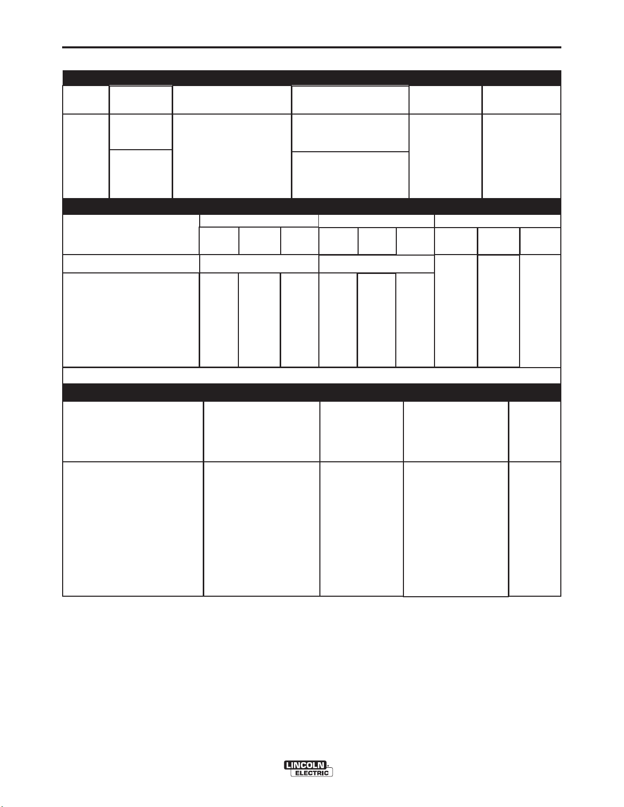
TECHNICAL SPECIFICATIONS - POWER WAVE®S350
POWER SOURCE-INPUT VOLTAGE AND CURRENT
Model
Duty Cycle
Input Voltage ± 10%
Input Amperes
(1 Phase in parenthesis)
Idle Power
A-1
Power Factor @
Rated Output
39/35/20/17/14
(NA/65***/37/32/25)
30/28/16/14/11
(56/51/29/25/20)
300 Watts Max.
(fan on)
K2823-1
40% rating
100% rating
200-208/230/380-415/
460/575
50/60 Hz
RATED OUTPUT
INPUT
VOLTAGE / PHASE /
FREQUENCY
200-208/1/50/60
230/1/50/60
460/1/50/60
575/1/50/60
200-208/3/50/60
230/3/50/60
380-415/3/50/60
460/3/50/60
575/3/50/60
*** On 230 Volt / 1 phase inputs the max. rating is at a duty cycle of 30%, except for GTAW processes.
40%***
350
Amps
31.5
Volts
RECOMMENDED INPUT WIRE AND FUSE SIZES
INPUT
VOLTAGE / PHASE/
FREQUENCY
INPUT AMPERE RAT-
ING AND DUTY CYCLE
GMAW
60%
300 Amps / 29 Volts
320
Amps
30
Volts
MAXIMUM
100%
300
Amps
29
Volts
SMAW
(mm
60%
275
Amps
31
Volts
2
)
100%
Amps
3
40%***
250 Amps / 30 Volts
325
Amps
33
Volts
CORD SIZE
AWG SIZES
GTAW-DC
40%
250
30
Volts
TIME DELAY FUSE
350
Amps
24 Volts
1
OR BREAKER
AMPERAGE
60%
325
Amps
23Volts
2
.95
100%
300
Amps
22 Volts
NOTES
200-208/1/50/60
200-208/3/50/60
230/1/50/60
230/3/50/60
380-415/1/50/60
380-415/3/50/60
460/1/50/60
460/3/50/60
575/1/50/60
575/3/50/60
1. Based on U.S. National electrical Code
2. Also called " inverse time" or "thermal / magnetic" circuit breakers; circuit breakers that have a delay in trip-
ping action that decreases as the magnitude of the current increases
3. Type SO cord or similar in 30° C ambient
4. When operating on these inputs, the line cord should be changed to an input conductor of 6 AWG or larger.
60A, 100%
39A, 40%
67A, 30%
35A, 40%
38A, 40%
19A, 40%
34A, 40%
17A, 40%
27A, 40%
14A, 40%
POWER WAVE®S350
6 (13)
8 (10)
4 (16)
8 (10)
8 (10)
12 (4)
8 (10)
12 (4)
10 (6)
14 (2.5)
80
50
80
45
50
30
45
25
35
20
NOTE 4
NOTE 4
Page 9

A-2
PROCESS
GMAW
GMAW-Pulse
FCAW
GTAW-DC
SMAW
PHYSICAL DIMENSIONS
MODEL
HEIGHT
INSTALLATION
WELDING PROCESS
OUTPUT RANGE (AMPERES)
5-350
WIDTH
OCV (Uo)
Mean Peak
40-70
40-70
40-70 100V
24
60
DEPTH
A-2
WEIGHT
K2823-1
20.40 in ( 518 mm)
14.00in ( 356 mm)
TEMPERATURE RANGES
OPERATING TEMPERATURE RANGE
Environmentally Hardened: -4°F to 104°F (-20C to 40C)
IP23 155º(F) Insulation Class
* Weight does not include input cord.
IEC 60974-1
24.80in ( 630mm)
STORAGE TEMPERATURE RANGE
Environmentally Hardened: -40°F to 185°F (-40C to 85C)
85 lbs (39 kg)*
POWER WAVE®S350
Page 10
A-3
INSTALLATION
A-3
SAFETY PRECAUTIONS Read this
entire installation section before you start installa-
tion.
WARNING
ELECTRIC SHOCK can kill.
• Only qualified personnel should
perform this installation.
• Turn the input power OFF at the
disconnect switch or fuse box before working on
this equipment. Turn off the input power to any
other equipment connected to the welding system
at the disconnect switch or fuse box before working on the equipment.
• Do not touch electrically hot parts.
• Always connect the POWER WAVE
grounding lug to a proper safety (Earth) ground.
-------------------------------------------------------------
®
S350
SELECT SUITABLE LOCATION
The POWER WAVE®S350 will operate in harsh environments. Even so, it is important that simple preventative measures are followed in order to assure long
life and reliable operation.
LIFTING
Both handles should be used when lifting POWER WAVE
S350. When using a crane or overhead device a lifting strap
should be connected to both handles. Do not attempt to lift the
POWER WAVE
®
S350 with accessories attached to it.
®
WARNING
• Lift only with equipment of adequate lifting capacity.
• Be sure machine is stable when
lifting.
• Do not operate machine while
suspended when lifting.
FALLING
EQUIPMENT can
cause injury.
-------------------------------------------------------------
STACKING
The POWER WAVE®S350 cannot be stacked.
TILTING
Place the machine directly on a secure, level surface or on a
recommended undercarriage. The machine may topple over if
this procedure is not followed.
• The machine must be located where there is free
circulation of clean air such that air movement in
the back, out the sides and bottom will not be
restricted.
• Dirt and dust that can be drawn into the machine
should be kept to a minimum. The use of air filters
on the air intake is not recommended because normal air flow may be restricted. Failure to observe
these precautions can result in excessive operating
temperatures and nuisance shutdown.
• Keep machine dry. Shelter from rain and snow. Do
not place on wet ground or in puddles.
• Do not mount the POWER WAVE
bustible surfaces. Where there is a combustible
surface directly under stationary or fixed electrical
equipment, that surface shall be covered with a
steel plate at least .060” (1.6mm) thick, which shall
extend not less than 5.90” (150mm) beyond the
equipment on all sides.
®
S350 over com-
INPUT AND GROUND CONNECTIONS
Only a qualified electrician should connect the POWER WAVE
S350. Installation should be made in accordance with the
appropriate National Electrical Code, all local codes and the
information in this manual.
®
MACHINE GROUNDING
The frame of the welder must be grounded. A ground terminal
marked with a ground symbol is located next to the input
power connection block.
See your local and national electrical codes for proper grounding methods.
HIGH FREQUENCY PROTECTION
The EMC classification of the POWER WAVE
Industrial, Scientific and Medical (ISM) group 2, class A. The
®
POWER WAVE
L10093 for further details).
Locate the POWER WAVE
machinery. The normal operation of the POWER WAVE
may adversely affect the operation of RF controlled equipment,
which may result in bodily injury or damage to the equipment.
S350 is for industrial use only. (See print
®
S350 away from radio controlled
®
S350 is
®
S350
POWER WAVE®S350
Page 11
A-4
INSTALLATION
A-4
INPUT CONNECTION
WARNING
Only a qualified electrician should
connect the input leads to the
POWER WAVE
should be made in accordance with
all local and national electrical
codes and the connection diagrams. Failure to do
so may result in bodily injury or death.
-------------------------------------------------------------
A 10 ft. (3.0m) power cord is provided and wired into
the machine.
For Single Phase Input
Connect green lead to ground per National Electrical
Code.
Connect black and white leads to power.
Wrap red lead with tape to provide 600V insulation.
For Three Phase Input
Connect green lead to ground per National Electric
Code.
®
S350. Connections
WARNING
The POWER WAVE®S350 ON/OFF
switch is not intended as a service
disconnect for this equipment. Only
a qualified electrician should con-
®
nect the input leads to the POWER WAVE
S350.
Connections should be made in accordance with
all local and national electrical codes and the connection diagram located on the inside of the
reconnect access door of the machine. Failure to
do so may result in bodily injury or death.
------------------------------------------------------------------------
POWER CORD REPLACEMENT
WARNING
Only a qualified electrician should
connect the input leads to the
POWER WAVE
should be made in accordance with
all local and national electrical
codes and the connection diagrams. Failure to do so may result in bodily injury
or death.
®
S350. Connections
Connect black, red and white leads to power.
INPUT FUSE AND SUPPLY WIRE
CONSIDERATIONS
Refer to Specification Section for recommended fuse,
wire sizes and type of the copper wires. Fuse the
input circuit with the recommended super lag fuse or
delay type breakers (also called "inverse time" or
"thermal/magnetic" circuit breakers). Choose input
and grounding wire size according to local or national
electrical codes. Using input wire sizes, fuses or circuit breakers smaller than recommended may result in
"nuisance" shut-offs from welder inrush currents, even
if the machine is not being used at high currents.
INPUT VOLTAGE SELECTION
The POWER WAVE®S350 automatically adjusts to
work with different input voltages. No reconnect
switches settings are required.
------------------------------------------------------------------------
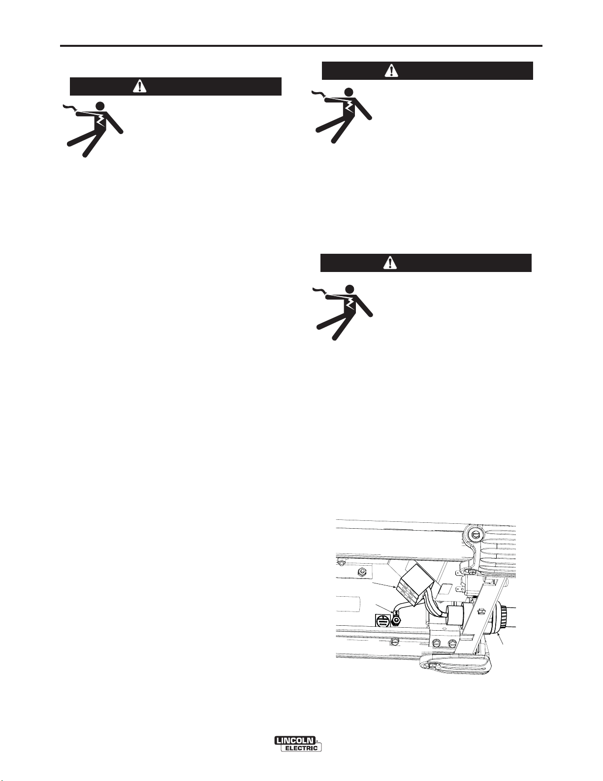
If the input power cord is damaged or needs to be
replaced an input power connection block is located
in the back of the machine with the access panel
removed as shown Figure A.1.
ALWAYS CONNECT THE POWER WAVE GROUND-
ING LUG (LOCATED AS SHOWN IN FIGURE A.1)
TO A PROPER SAFETY (EARTH) GROUND.
FIGURE A.1
CONNECTION
BLOCK
GROUND
LUG
INPUT
POWER
CORD
POWER WAVE®S350
Page 12
A-5
K87870
CONNECTION DIAGRAMS
INSTALLATION
SMAW (STICK) WELDING
A-5
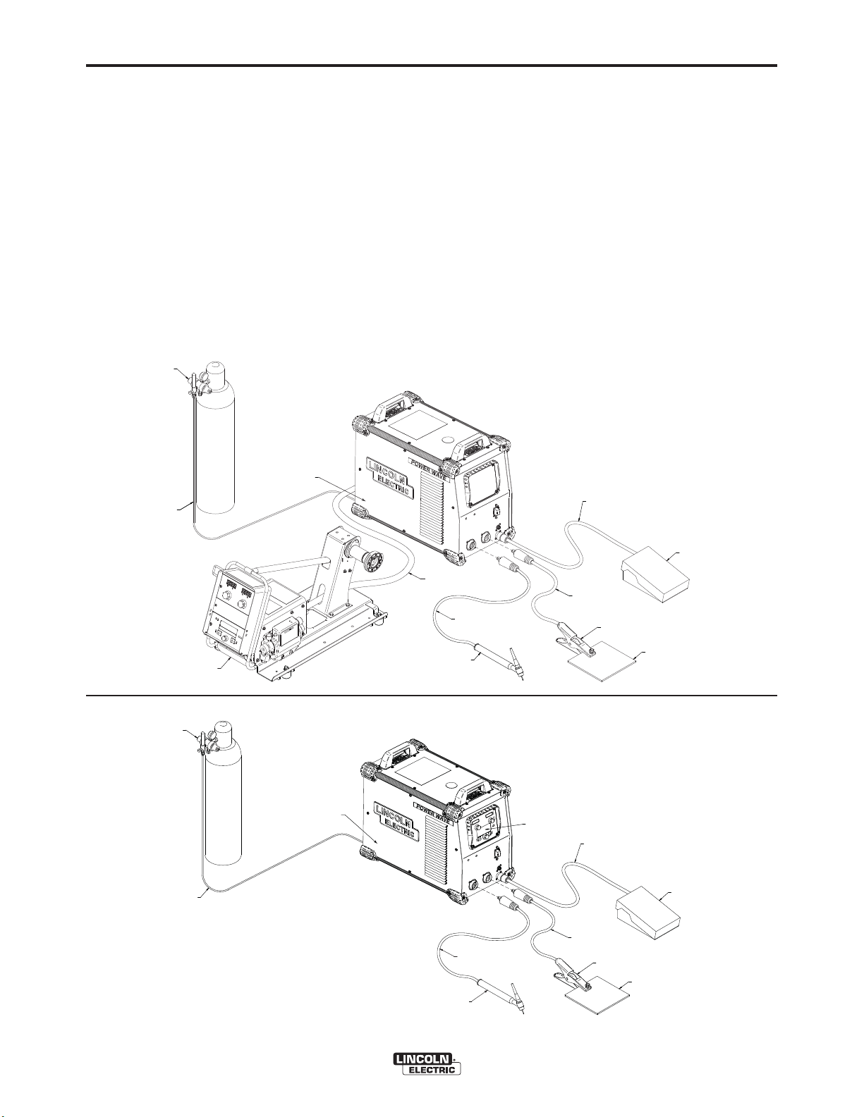
GTAW (TIG) WELDING
A user interface is required for adjusting the TIG welding settings. A Power Feed wire feeder can be used as
the user interface (Figure A.2), or a S-series user interface (K2828-1) can be installed into the power source
(Figure A.3). Refer to the connection diagrams based
on the user interface that is being used. For either setup the K2825-1 solenoid kit is recommended for controlling the gas. Alternate configurations are possible
depending on the wire feeder that is being used. Refer
to the wire feederʼs manual for alternative configurations.
FIGURE A.2
REGULATOR
FLOWMETER
GAS HOSE
GAS SOLENOID KIT
(INSIDE MACHINE)
K2825-1
TIG WITH POWER FEED USER INTERFACE
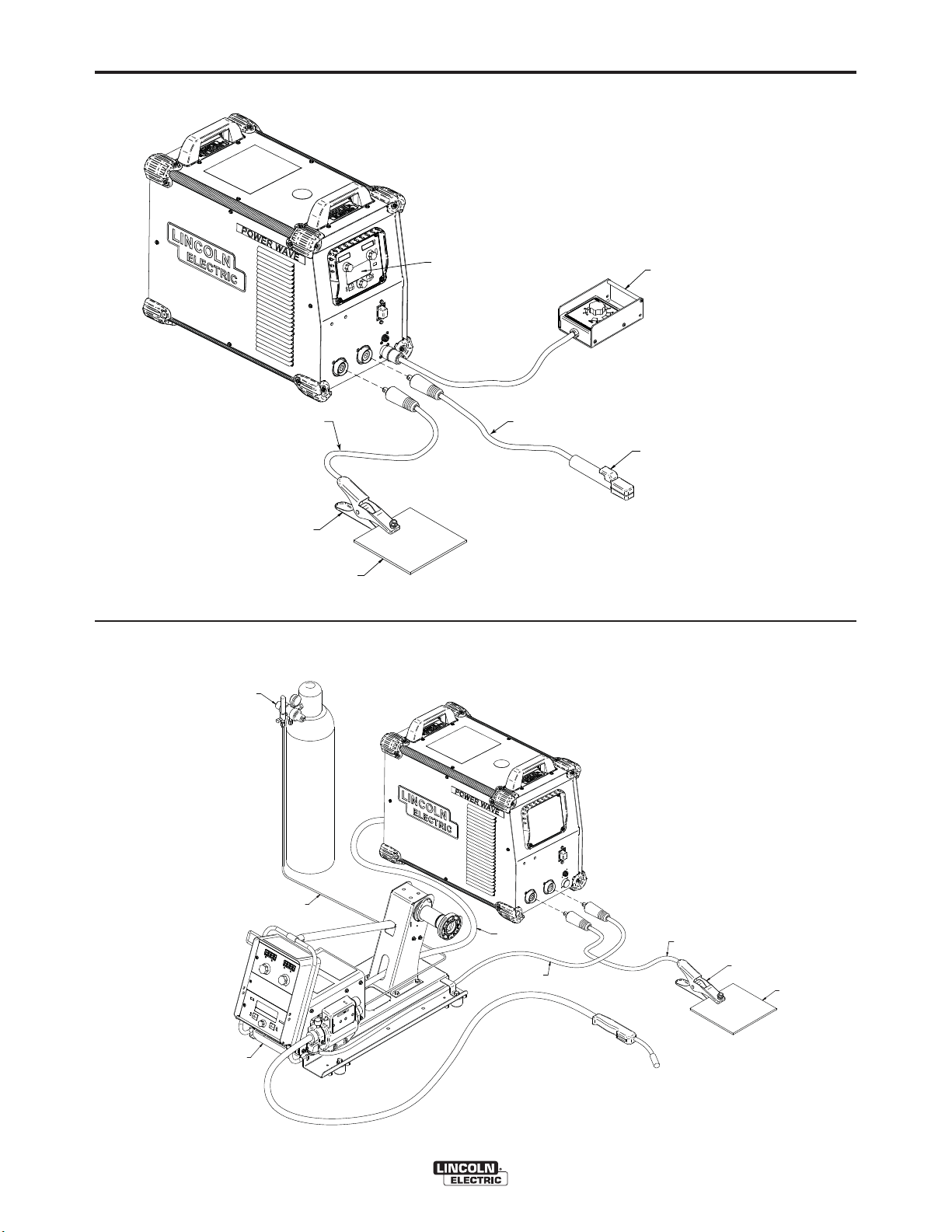
Similar to TIG welding a user interface is required for
adjusting the Stick welding settings. A Power Feed
wire feeder can be used as the user interface, or a
K2828-1 (user interface control panel) can be installed
into the power source (Figure A.4). The connection
diagram shown is based on the S-Series user interface (K2828-1). In this diagram the remote control box
is optional.
GMAW (MIG) WELDING
An arclink compatible wire feeder is recommended for
Mig welding. Refer to Figure A.5 for the connection
details.
TO REMOTE CONTROL
RECEPTACLE
REGULATOR
FLOWMETER
GAS HOSE
PF10-M
WIRE FEEDER
GAS SOLENOID KIT
(INSIDE MACHINE)
K2825-1
ARCLINK CABLE
K1543-[XX]
TO NEGATIVE
(-) STUD
TIG TORCH
K2266-1 KIT
(INCLUDES WORK CLAMP,
ADAPTER, AND REGULATOR)
FIGURE A.3
TIG WITH S-SERIES USER INTERFACE
USER INTERFACE
CONTROL PANEL
K2828-1
TO NEGATIVE
(-) STUD
TIG TORCH
K2266-1 KIT
(INCLUDES WORK CLAMP,
ADAPTER, AND REGULATOR)
POWER WAVE®S350
TO POSITIVE
(+) STUD
TO POSITIVE
(+) STUD
WORK CLAMP
WORK PIECE
TO REMOTE CONTROL
RECEPTACLE
WORK CLAMP
WORK PIECE
FOOT AMPTROL
FOOT AMPTROL
K870
Page 13
A-6
INSTALLATION
FIGURE A.4
STICK WITH S-SERIES USER INTERFACE
A-6
TO NEGATIVE
(-) STUD
WORK CLAMP
REGULATOR
FLOWMETER
WORK PIECE
USER INTERFACE
CONTROL PANEL
K2828-1
FIGURE A.5
MIG PROCESS
TO POSITIVE
(+) STUD
REMOTE CONTROL BOX
K857
ELECTRODE HOLDER KIT
K2394-1 KIT
(INICLUDES GROUND CLAMP)
PF10-M
WIRE FEEDER
GAS HOSE
ARCLINK CABLE
K1543-[XX]
TO POSITIVE
(+) STUD
POWER WAVE®S350
TO NEGATIVE (-) STUD
WORK CLAMP
WORK PIECE
Page 14
A-7
INSTALLATION
A-7
RECOMMENDED WORK CABLE
SIZES FOR ARC WELDING
Connect the electrode and work cables between the
appropriate output studs of the Power Wave
per the following guidelines:
• Most welding applications run with the electrode
being positive (+). For those applications, connect
the electrode cable between the wire drive feed plate
and the positive (+) output stud on the power source.
Connect a work lead from the negative (-) power
source output stud to the work piece
• When negative electrode polarity is required, such
as in some Innershield applications, reverse the output connections at the power source (electrode cable
to the negative (-) stud, and work cable to the positive (+) stud).
®
S350
CAUTION
Negative electrode polarity operation WITHOUT
use of a remote work sense lead (21) requires the
Negative Electrode Polarity attribute to be set. See
the Remote Sense Lead Specification section of
this document for further details.
-----------------------------------------------------------------------
For additional Safety information regarding the electrode and work cable set-up, See the standard “SAFETY INFORMATION” located in the front of the
Instruction Manuals.
OUTPUT CABLE GUIDELINES (Table A.1)
General Guidelines
• Select the appropriate size cables per the “Output
Cable Guidelines” below. Excessive voltage drops
caused by undersized welding cables and poor connections often result in unsatisfactory welding performance. Always use the largest welding cables (electrode and work) that are practical, and be sure all
connections are clean and tight.
Note: Excessive heat in the weld circuit indicates
undersized cables and/or bad connections.
• Route all cables directly to the work and wire feeder,
avoid excessive lengths and do not coil excess
cable. Route the electrode and work cables in close
proximity to one another to minimize the loop area
and therefore the inductance of the weld circuit.
• Always weld in a direction away from the work
(ground) connection.
Table A.1 shows copper cable sizes recommended for
different currents and duty cycles. Lengths stipulated
are the distance from the welder to work and back to
the welder again. Cable sizes are increased for
greater lengths primarily for the purpose of minimizing
cable drop.
Percent Duty
Amperes
200
200
250
250
250
250
300
300
350
** Tabled values are for operation at ambient temperatures of 104°F (40°C) and below. Applications above 104°F (40°C) may
require cables larger than recommended, or cables rated higher than 167°F (75°C).
Cycle
60
100
30
40
60
100
60
100
40
CABLE SIZES FOR COMBINED LENGTHS OF ELECTRODE AND WORK
CABLES [RUBBER COVERED COPPER - RATED
0 to 50 Ft.
2
2
3
2
1
1
1
2/0
1/0
50 to 100 Ft.
2
2
3
2
1
1
1
2/0
1/0
POWER WAVE®S350
100 to 150 Ft.
2
2
2
1
1
1
1
2/0
2/0
167°F (75°C)]**
150 to 200 Ft.
1
1
1
1
1
1
1/0
2/0
2/0
200 to 250 Ft.
1/0
1/0
1/0
1/0
1/0
1/0
2/0
3/0
3/0
Page 15
A-8
INSTALLATION
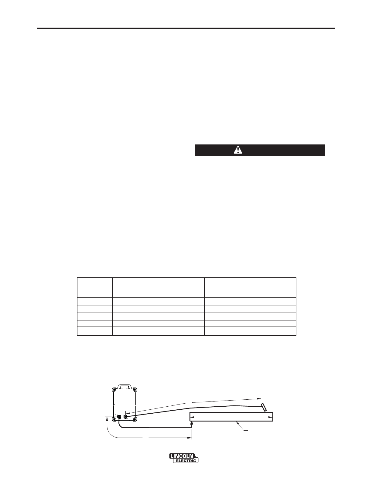
CABLE INDUCTANCE AND ITS
EFFECTS ON WELDING
Excessive cable inductance will cause the welding
performance to degrade. There are several factors
that contribute to the overall inductance of the cabling
system including cable size, and loop area. The loop
area is defined by the separation distance between
the electrode and work cables, and the overall welding
loop length. The welding loop length is defined as the
total of length of the electrode cable (A) + work cable
(B) + work path (C) (See Figure A.6).
To minimize inductance always use the appropriate
size cables, and whenever possible, run the electrode
and work cables in close proximity to one another to
minimize the loop area. Since the most significant factor in cable inductance is the welding loop length,
avoid excessive lengths and do not coil excess cable.
For long work piece lengths, a sliding ground should
be considered to keep the total welding loop length as
short as possible.
REMOTE SENSE LEAD
SPECIFICATIONS
Voltage Sensing Overview
The best arc performance occurs when the Power
®
Wave
tions.
S350 has accurate data about the arc condi-
TABLE A.2
Process
Electrode Voltage Sensing
67 lead
A-8
Depending upon the process, inductance within the
electrode and work cables can influence the voltage
apparent at the studs of the welder, and have a dramatic effect on performance. Remote voltage sense
leads are used to improve the accuracy of the arc voltage information supplied to the control pc board.
Sense Lead Kits (K940-xx) are available for this purpose.
The Power Wave
ly sense when remote sense leads are connected.
With this feature there are no requirements for settingup the machine to use remote sense leads. This feature can be disabled through the Weld Manager Utility
(available at www.powerwavesoftware.com) or
through the set up menu (if a user interface is installed
into the power source).
®
S350 has the ability to automatical-
CAUTION
If the auto sense lead feature is disabled and
remote voltage sensing is enabled but the sense
leads are missing, improperly connected extremely high welding outputs may occur.
------------------------------------------------------------------------
General Guidelines for Voltage Sense Leads
Sense leads should be attached as close to the weld
as practical, and out of the weld current path when
possible. In extremely sensitive applications it may be
necessary to route cables that contain the sense
leads away from the electrode and work welding
cables.
Voltage sense leads requirements are based on the
weld process (See Table A.2)
(1)
Work Voltage Sensing
21 lead
(2)
GMAW
GMAW-P
FCAW
GTAW
SMAW
(1)
The electrode voltage sense lead (67) is automatically enabled by the weld process, and integral to the 5 pin arclink control cable (K1543xx).
(2)
When a work voltage sense lead (21) is connected the power source will automatically switch over to using this feedback (if the auto
sense feature is enable).
POWER
WAVE
S350
67 lead required
67 lead required
67 lead required
Voltage sense at studs
Voltage sense at studs
FIGURE A.6
A
B
POWER WAVE®S350
21 lead optional
21 lead optional
21 lead optional
Voltage sense at studs
Voltage sense at studs
C
WORK
Page 16

A-9
Electrode Voltage Sensing
The remote ELECTRODE sense lead (67) is built into
the 5-pin arclink control cable (K1543-xx) and is
always connected to the wire drive feed plate when a
wire feeder is present. Enabling or disabling electrode
voltage sensing is application specific, and automatically configured by the active weld mode.
Work Voltage Sensing
®
The Power Wave
sense work voltage at the negative output stud (positive output polarity with remote Work Voltage Sensing
disabled).
S350 is configured at the factory to
INSTALLATION
A-9
Negative Electrode Polarity
The Power Wave
ly sense the polarity of the sense leads. With this feature there are no set-up requirements for welding with
negative electrode polarity. This feature can be disabled through the Weld Manager Utility (available at
www.powerwavesoftware.com) or through the set up
menu (if a user interface is installed into the power
source).
®
S350 has the ability to automatical-
CAUTION
If the auto sense lead feature is disabled and the
weld polarity attribute is improperly configured
extremely high welding outputs may occur.
------------------------------------------------------------------------
While most applications perform adequately by sensing the work voltage directly at the output stud, the
use of a remote work voltage sense lead is recommended for optimal performance. The remote WORK
sense lead (21) can be accessed through the four-pin
voltage sense connector located on the control panel
by using the K940 Sense Lead Kit. It must be
attached to the work as close to the weld as practical,
but out of the weld current path. For more information
regarding the placement of remote work voltage
sense leads, see the section entitled "Voltage Sensing
Considerations for Multiple Arc Systems."
POWER WAVE®S350
Page 17
A-10
INSTALLATION
A-10
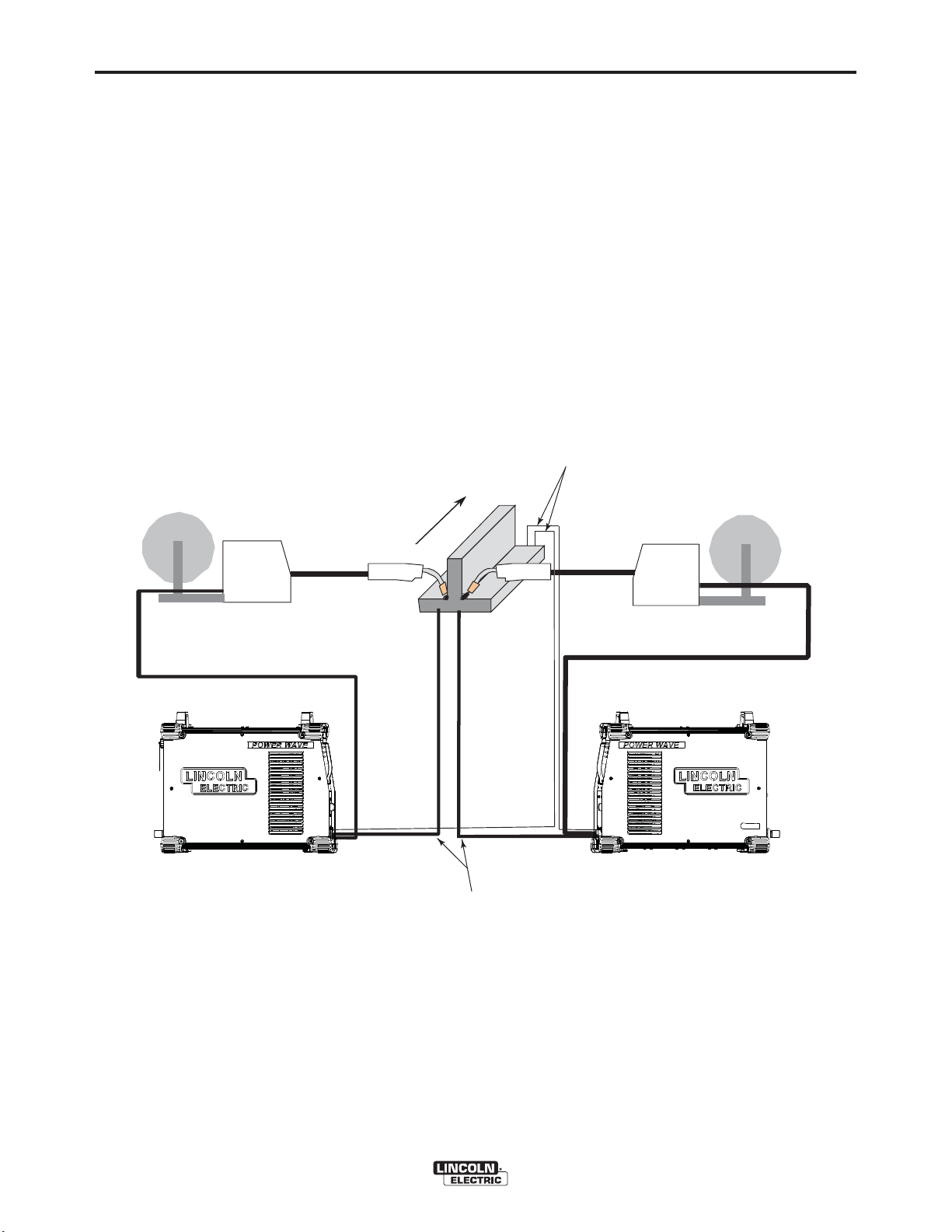
VOLTAGE SENSING
CONSIDERATIONS FOR MULTIPLE
ARC SYSTEMS
Special care must be taken when more than one arc
is welding simultaneously on a single part. Multiple arc
applications do not necessarily dictate the use of
remote work voltage sense leads, but they are strongly recommended.
If Sense Leads ARE NOT Used:
• Avoid common current paths. Current from adjacent arcs can induce voltage into each others current paths that can be misinterpreted by the power
sources, and result in arc interference.
FIGURE A.7
DIRECTION
OF TRAVEL
If Sense Leads ARE Used:
• Position the sense leads out of the path of the weld
current. Especially any current paths common to
adjacent arcs. Current from adjacent arcs can
induce voltage into each others current paths that
can be misinterpreted by the power sources, and
result in arc interference.
• For longitudinal applications, connect all work leads
at one end of the weldment, and all of the work voltage sense leads at the opposite end of the weldment. Perform welding in the direction away from
the work leads and toward the sense leads.
(See Figure A.7)
CONNECT ALL SENSE
LEADS AT THE END
OF THE WELD.
CONNECT ALL
WORK LEADS AT
THE BEGINNING
OF THE WELD.
POWER WAVE®S350
Page 18
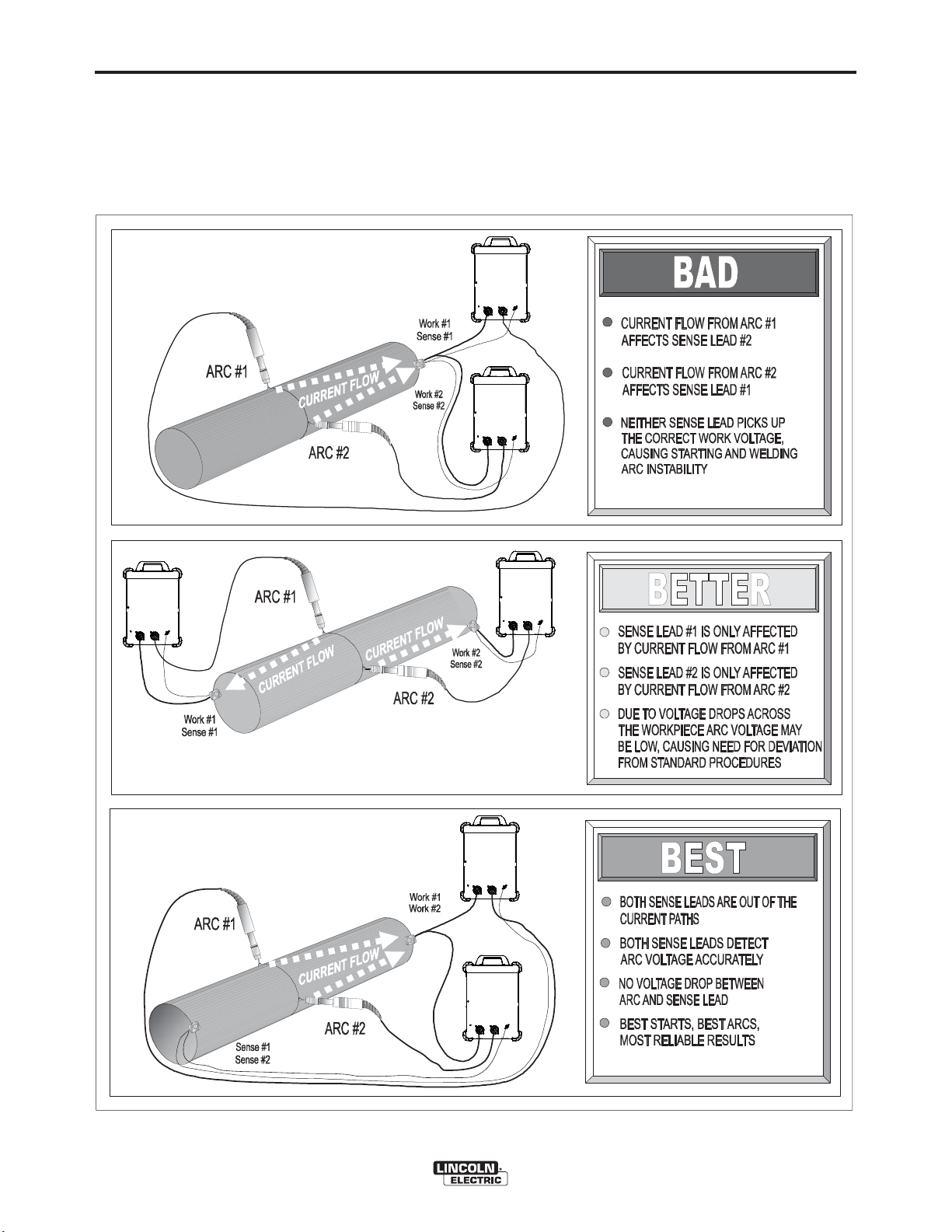
A-11
INSTALLATION
• For circumferential applications, connect all work
leads on one side of the weld joint, and all of the
work voltage sense leads on the opposite side,
such that they are out of the current path.
(See Figure 8.A)
FIGURE A.8
POWER
SOURCE
#1
WER
PO
SOURCE
#2
A-11
POWER
SOURCE
#1
WER
PO
SOURCE
#1
POWER
SOURCE
#2
WER
PO
SOURCE
#2
POWER WAVE®S350
Page 19

A-12
INSTALLATION
A-12
CONTROL CABLE CONNECTIONS
General Guidelines
Genuine Lincoln control cables should be used at all
times (except where noted otherwise). Lincoln cables
are specifically designed for the communication and
power needs of the Power Wave
tems. Most are designed to be connected end to end
for ease of extension. Generally, it is recommended
that the total length not exceed 100ft. (30.5m). The
use of non-standard cables, especially in lengths
greater than 25 feet, can lead to communication problems (system shutdowns), poor motor acceleration
(poor arc starting), and low wire driving force (wire
feeding problems). Always use the shortest length of
control cable possible, and DO NOT coil excess
cable.
Regarding cable placement, best results will be
obtained when control cables are routed separate
from the weld cables. This minimizes the possibility of
interference between the high currents flowing
through the weld cables, and the low level signals in
the control cables. These recommendations apply to
all communication cables including ArcLink
Ethernet connections.
®
/ Power Feed sys-
®
and
Connection Between Power Source and Ethernet
Networks
The Power Wave
®
S350 is equipped with an IP67
rated ODVA compliant RJ-45 Ethernet connector,
which is located on the rear panel. All external
Ethernet equipment (cables, switches, etc.), as
defined by the connection diagrams, must be supplied
by the customer. It is critical that all Ethernet cables
external to either a conduit or an enclosure are solid
conductor, shielded cat 5e cable, with a drain. The
drain should be grounded at the source of transmission. For best results, route Ethernet cables away
from weld cables, wire drive control cables, or any
other current carrying device that can create a fluctuating magnetic field. For additional guidelines refer to
ISO/IEC 11801. Failure to follow these recommendations can result in an Ethernet connection failure during welding.
Product specific Installation Instructions
Connection Between Power Source and ArcLink
Compatible Wirefeeders (K1543 – ArcLink Control
Cable)
The 5-pin ArcLink control cable connects the power
source to the wire feeder. The control cable consists
of two power leads, one twisted pair for digital communication, and one lead for voltage sensing. The 5pin ArcLink connection on the Power Wave
®
S350 is
located on the rear panel above the power cord. The
control cable is keyed and polarized to prevent
improper connection. Best results will be obtained
when control cables are routed separate from the
weld cables, especially in long distance applications.
The recommended combined length of the ArcLink
control cable network should not exceed 200ft.
(61.0m).
®
POWER WAVE®S350
Page 20

B-1
OPERATION
B-1
SAFETY PRECAUTIONS
READ AND UNDERSTAND ENTIRE SECTION
BEFORE OPERATING MACHINE.
WARNING
• ELECTRIC SHOCK CAN KILL.
• Do not touch electrically live
part or electrode with skin or
wet clothing.
• Insulate yourself from work and
ground.
• Always wear dry insulating gloves.
• Do not operate with covers, panels or guards
removed or open.
---------------------------------------------------------------------
• FUMES AND GASSES can be
dangerous.
• Keep your head out of fumes.
Use ventilation or exhaust to
•
remove fumes from breathing
zone.
---------------------------------------------------------------------
• WELDING SPARKS can cause
fire or explosion.
• Keep flammable material away.
GRAPHIC SYMBOLS THAT APPEAR ON
THIS MACHINE OR IN THIS MANUAL
WARNING OR
CAUTION
DANGEROUS
VOLTAGE
POSITIVE OUTPUT
NEGATIVE OUTPUT
HIGH TEMPERATURE
STATUS
---------------------------------------------------------------------
ARC RAYS can burn.
Wear eye, ear and body protec-
•
tion.
---------------------------------------------------------------------
SEE ADDITIONAL WARNING INFORMATION
UNDER ARC WELDING SAFETY PRECAUTIONS
AND IN THE
UAL.
---------------------------------------------------------------------
FRONT OF THIS OPERATING MAN-
PROTECTIVE
GROUND
EXPLOSION
POWER-UP SEQUENCE
When the POWER WAVE®S350 is powered up, it can
take as long as 30 seconds for the machine to be
ready to weld. During this time period the user inter-
face will not be active.
DUTY CYCLE
The duty cycle is based on a ten-minute period. A
40% duty cycle represents 4 minutes of welding and 6
minutes of idling in a ten-minute period. Refer to the
technical specification section for the Power Wave®
S350ʼs duty cycle ratings.
POWER WAVE®S350
Page 21

B-2
OPERATION
B-2
PRODUCT DESCRIPTION
PRODUCT SUMMARY
The Power Wave
power source with high-end functionality capable of
Stick, DC TIG, MIG, Pulsed MIG and Flux-Cored
welding. It is ideal for a wide variety of materials
including aluminum, stainless, and nickel — where arc
performance is critical.
The Power Wave
ble welding system. Like existing Power Waveʼs, the
software based architecture allows for future upgradeability. One significant change from the current range
of Power Wave units is that the Ethernet communication feature is standard on the Power Wave
which allows for effortless software upgrades through
Powerwavesoftware.com. The Ethernet communication also gives the Power Wave
run Production Monitoring™ 2. Also a Devicenet
option which will allow the Power Wave
used in a wide range of configurations. Also, the
Power Wave
ble with future advanced welding modules like STT
®
S350 is a portable multi-process
®
S350 is designed to be a very flexi-
®
S350
®
S350 the ability to
®
S350 to be
®
S350 is being designed to be compati-
PROCESS LIMITATIONS
The software based weld tables of the Power Wave
S350 limit the process capability within the output
range and the safe limits of the machine. In general
the processes will be limited to .030-.052 solid steel
wire, .030-.045 stainless wire, .035-1/16 cored wire,
and .035 and 1/16 Aluminum wire.
EQUIPMENT LIMITATIONS
Only ArcLink compatible semiautomatic wire feeders
and users interfaces may be used. If other Lincoln
wire feeders or non-Lincoln wire feeders are used
there will be limited process capability and performance and features will be limited.
®
RECOMMENDED PROCESSES AND
EQUIPMENT
The Power Wave®S350 is recommended for semiautomatic
welding, and may also be suitable for basic hard automation
applications. The Power Wave
number of configurations, some requiring optional equipment or welding programs.
RECOMMENDED EQUIPMENT
The Power Wave®S350 is designed to be compatible
with the current range of Power Feed™ systems
including future versions of ArcLink
RECOMMENDED PROCESSES
The Power Wave® S350 is a high speed, multiprocess power source capable of regulating the current, voltage, or power of the welding arc. With an output range of 5 to 350 amperes, it supports a number
of standard processes including synergic GMAW,
GMAW-P, FCAW, FCAW-SS, SMAW, GTAW and
GTAW-P on various materials especially steel, aluminum and stainless.
®
S350 can be set up in a
®
feeders.
POWER WAVE®S350
Page 22

B-3
OPERATION
DESIGN FEATURES
Loaded with Standard Features
• Multiple process DC output range: 5 - 350 Amps
• 200 – 600 VAC, 1/3 phase, 50-60Hz input power
• New and Improved Line Voltage Compensation
holds the output constant over wide input voltage
fluctuations.
B-3
• Utilizes next generation microprocessor control,
based on the ArcLink
• State of the art power electronics technology yields
superior welding capability.
• Electronic over current protection
• Input over voltage protection.
• F.A.N. (fan as needed). Cooling fan only runs
when needed.
• Thermostatically protected for safety and reliability.
• Recessed connection panel for protection against
accidental impact.
• Ethernet connectivity via IP-67 rated ODVA compliant RJ-45 connector.
• Panel mounted Status and Thermal LED indicators
facilitate quick and easy troubleshooting.
• Potted PC boards for enhanced ruggedness/reliability.
®
platform.
• Enclosure reinforced with heavy duty aluminum
extrusions for mechanical toughness
• Remote control/Foot amptrol ready.
• Waveform Control Technology™ for good weld
appearance and low spatter, even when welding
nickel alloys.
POWER WAVE®S350
Page 23

B-4
OPERATION
B-4
CASE FRONT CONTROLS
(See Figure B.1)
1. USER INTERFACE (optional)
2. STATUS LED - (See Troubleshooting Section for
operational functions)
3. THERMAL LED - Indicates when machine has
thermal fault.
4. POWER SWITCH - Controls power to the Power
5. WORK STUD
6. ELECTRODE STUD
7. WORK SENSE LEAD
8. 6-PIN REMOTE
Wave
®
S350.
CASE BACK CONTROLS
(See Figure B.2)
1. 115 VAC RECEPTACLE AND CIRCUIT BEAKER
(OPTIONAL)
2. ARCLINK (RECEPTACLE AND CIRCUIT
BREAKER)
3. RESERVED FOR FUTURE DEVELOPMENT
4. DEVICENET KIT (OPTIONAL)
5. ETHERNET
6. RESERVED FOR FUTURE DEVELOPMENT
7. SOLENOID KIT (OPTIONAL)
8. INPUT POWER CORD
FIGURE B.1
1
1
2
2
3
4
5
3
4
8
FIGURE B.2
5
6
7
6
7
8
POWER WAVE®S350
Page 24

B-5
OPERATION
B-5
COMMON WELDING PROCEDURES
WARNING
MAKING A WELD
The serviceability of a product or structure utilizing the welding programs is and must be the sole
responsibility of the builder/user. Many variables
beyond the control of The Lincoln Electric
Company affect the results obtained in applying
these programs. These variables include, but are
not limited to, welding procedure, plate chemistry
and temperature, weldment design, fabrication
methods and service requirements. The available
range of a welding program may not be suitable
for all applications, and the build/user is and must
be solely responsible for welding program selection.
Choose the electrode material, electrode size, shielding gas, and process (GMAW, GMAW-P etc.) appropriate for the material to be welded.
Select the weld mode that best matches the desired
welding process. The standard weld set shipped with
the Power Wave
common processes that will meet most needs. If a
special weld mode is desired, contact the local Lincoln
Electric sales representative.
All adjustments are made through the user interface.
Because of the different configuration options your
system may not have all of the following adjustments.
See Accessories Section for Kits and Options avaliable to use with the Power Wave
®
S350 encompasses a wide range of
®
S350.
Basic Welding Controls
Weld Mode
Selecting a weld mode determines the output characteristics of the Power Wave
®
power source. Weld
modes are developed with a specific electrode material, electrode size, and shielding gas. For a more complete description of the weld modes programmed into
®
the Power Wave
S350 at the factory, refer to the
Weld Set Reference Guide supplied with the machine
or available at www.powerwavesoftware.com.
Wire Feed Speed (WFS)
In synergic welding modes (synergic CV, GMAW-P),
WFS is the dominant control parameter. The user
adjusts WFS according to factors such as wire size,
penetration requirements, heat input, etc. The Power
®
Wave
S350 then uses the WFS setting to adjust the
voltage and current according to settings contained in
the Power Wave.
In non-synergic modes, the WFS control behaves like
a conventional power source where WFS and voltage
are independent adjustments. Therefore, to maintain
proper arc characteristics, the operator must adjust
the voltage to compensate for any changes made to
the WFS.
Amps
In constant current modes, this control adjusts the
welding amperage.
Volts
In constant voltage modes, this control adjusts the
welding voltage.
Definition of Welding Modes
NON-SYNERGIC WELDING MODES
• A Non-synergic welding mode requires all welding
process variables to be set by the operator.
SYNERGIC WELDING MODES
• A Synergic welding mode offers the simplicity of single knob control. The machine will select the correct
voltage and amperage based on the Wire Feed
Speed (WFS) set by the operator.
POWER WAVE®S350
Trim
In pulse synergic welding modes, the Trim setting
adjusts the arc length. Trim is adjustable from 0.50 to
1.50. 1.00 is the nominal setting and is a good starting point for most conditions.
UltimArc™ Control
UltimArc™ Control allows the operator to vary the arc
characteristics. UltimArc™ Control is adjustable from
–10.0 to +10.0 with a nominal setting of 0.0.
Page 25

B-6
SMAW (STICK) WELDING
The welding current and Arc Force settings can be set
through a Power Feed 10M or Power Feed 25M wire
feeder. Alternatively an optional Stick / TIG UI (K2828-
1) can be installed into the power source to control
these settings locally.
In a SMAW (STICK mode), Arc Force can be adjusted. It can be set to the lower range for a soft and less
penetrating arc characteristic (negative numeric values) or to the higher range (positive numeric values)
for a crisp and more penetrating arc. Normally, when
welding with cellulosic types of electrodes (E6010,
E7010, E6011), a higher energy arc is required to
maintain arc stability. This is usually indicated when
the electrode sticks to the work-piece or when the arc
becomes unstable during manipulative technique. For
low hydrogen types of electrodes (E7018, E8018,
E9018, etc.) a softer arc is usually desirable and the
lower end of the Arc Control suits these types of electrodes. In either case the arc control is available to
increase or decrease the energy level delivered to the
arc.
OPERATION
B-6
The nominal preprogrammed voltage is the best average voltage for a given wire feed speed, but may be
adjusted to preference. When the wire feed speed
changes, the Power Wave
adjusts the voltage level correspondingly to maintain
similar arc characteristics throughout the WFS range.
Non Synergic CV
In non-synergic modes, the WFS control behaves
more like a conventional CV power source where
WFS and voltage are independent adjustments.
Therefore to maintain the arc characteristics, the operator must adjust the voltage to compensate for any
changes made to the WFS.
All CV Modes
Pinch adjusts the apparent inductance of the wave
shape. The “pinch” function is inversely proportional
to inductance. Therefore, increasing Pinch Control
greater than 0.0 results in a crisper arc (more spatter)
while decreasing the Pinch Control to less than 0.0
provides a softer arc (less spatter).
®
S350 automatically
GTAW (TIG) WELDING
The welding current can be set through a Power Feed
10M or Power Feed 25M wire feeder. Alternatively an
optional Stick / TIG UI (K2828-1) can be installed into
the power source to control these settings locally.
The TIG mode features continuous control from 5 to
350 amps with the use of an optional foot amptrol
(K870). The Power Wave
Touch Start TIG mode or Scratch start TIG mode.
CONSTANT VOLTAGE WELDING
Synergic CV
For each wire feed speed, a corresponding voltage is
preprogrammed into the machine through special software at the factory.
®
S350 can be run in either a
FIGURE B.3
PULSE WELDING
Pulse welding procedures are set by controlling an
overall “arc length” variable. When pulse welding, the
arc voltage is highly dependent upon the waveform.
The peak current, back ground current, rise time, fall
time and pulse frequency all affect the voltage. The
exact voltage for a given wire feed speed can only be
predicted when all the pulsing waveform parameters
are known. Using a preset voltage becomes impractical and instead the arc length is set by adjusting
“trim”.
Trim adjusts the arc length and ranges from 0.50 to
1.50 with a nominal value of 1.00. Trim values greater
than 1.00 increase the arc length, while vales less
than 1.00 decrease the arc length. (See figure B.3)
POWER WAVE®S350
Page 26

B-7
OPERATION
Most pulse welding programs are synergic. As the
wire feed speed is adjusted, the Power Wave
®
S350
will automatically recalculate the waveform parameters to maintain similar arc properties.
B-7
The Power Wave
®
S350 utilizes “adaptive control” to
compensate for changes in the electrical stick-out
while welding. (Electrical stick-out is the distance
from the contact tip to the work piece.) The Power
®
Wave
S350 waveforms are optimized for a 0.75”
stick-out. The adaptive behavior supports a range of
stick-outs from 0.50 to 1.25”. At very low or high wire
feed speeds, the adaptive range may be less due to
reaching physical limitations of the welding process.
UltimArc™ Control adjusts the focus or shape of the
arc. UltimArc™ Control is adjustable from -10.0 to
+10.0 with a nominal setting of 0.0. Increasing the
UltimArc™ Control increases the pulse frequency and
background current while decreasing the peak current. This results in a tight, stiff arc used for high
speed sheet metal welding. Decreasing the
UltimArc™ Control decreases the pulse frequency
and background current while increasing the peak current. This results in a soft arc good for out of position
welding. (See Figure B.4)
FIGURE B.4
POWER WAVE®S350
Page 27

C-1
ACCESSORIES
C-1
KITS, OPTIONS AND ACCESSORIES
All Kits Options and Accessories are found on the
Web site: (www.lincolnelectric.com)
FACTORY INSTALLED
None Available
FIELD INSTALLED OPTIONS
GENERAL OPTIONS
Stick / Tig User Interface Kit
Mounts inside the front panel of the Power Wave®
S350. Allows stick and Tig operation without having a
wire feeder.
Order K2828-1
115 VAC Auxiliary Power Kit
Mounts inside the back of the Power Wave® S350.
Adds 115 VAC / 60 Hz auxiliary power capability to
the Power Wave® S350 ( only compatible with the
K2823-1 power source)
Order K2829-1
DeviceNet Kit
Mounts inside the back of the Power Wave® S350.
Allows Devicenet objects to communicate with the
Power Wave® S350.
Order K2827-1
Work Voltage Sense Lead Kit
Required to accurately monitor voltage at the arc.
Order K940-25 for 25 ft. (7.6 m)
Order K1811-75 for 75 ft. (22.9 m)
Deluxe Adjustable Gas Regulator & Hose Kit
Accommodates CO
ders. Includes a cylinder pressure gauge, dual scale
flow gauge and 4.3 ft. (1.3 m) gas hose.
Order K586-1
Work and Wire Feeder 2/0 Weld Cable Package
Includes Twist-Mate™ connectors, work clamps, 15 ft.
(4.5 m) work cable and 10 ft. (3.0 m) electrode cable.
Rated 350 amps, 60% duty cycle.
Order K1803-1
, Argon, or Argon-blend gas cylin-
2
Twist-Mate™ Cable Receptacle
For connecting welding cable to Twist-Mate™ Cable
Plug.
Order K1759-70 for 1/0-2/0 (50-70 mm2) cable
Order K1759-95 for 2/0-3/0 (70-95mm2) cable
Twist-Mate™ to Lug Adapter
For connection of lugged cable to Twist-Mate™ connectors. 18" (457 mm) long.
Order K2176-1
Inverter and Wire Feeder Cart
Rear-wheeled cart includes front casters and no-lift
gas bottle plat¬form. Convenient handles allow for
easy cable storage while full length side trays store
parts and tools. Shipped fully assembled. Small footprint fits through 30" (762 mm) door.
Order K1764-1 Dual Cylinder Kit
Dual Cylinder Kit
Permits side-by-side mounting of two full size gas
cylinders, with easy loading. For use with K1764-1
cart.
Order K1702-1
Coaxial Welding Cable
Optimum weld cables for minimizing cable inductance
and optimizing welding performance.
Order K1796-25 for 25 feet 25 ft. (7.6 m) cable
length.
Order K1796-50 for 50 feet 50 ft. (15.2 m) cable
length.
Order K1796-75 for 75 feet 75 ft. (22.9 m) cable
length.
Order K1796-100 for 100 feet 100 ft. (30.5 m) cable
length.
Welding Fume Extractors
Lincoln offers a wide range of fume extraction environmental system solutions, ranging from portable systems easily wheeled around a shop to shop-wide central systems servicing many dedicated welding stations.
Request Lincoln publication E13.40
(See www.lincolnelectric.com)
Twist-Mate™ Cable Plug
For connecting welding cable to output terminal recep-
2
tacles. For 1/0-2/0 (50-70 mm
Order K852-70
Twist-Mate™ Cable Plug
For connecting welding cable to output terminal receptacles. For 2/0-3/0 (70-95 mm
Order K852-95
) cable.
2
) cable.
POWER WAVE®S350
Page 28

C-2
ACCESSORIES
STICK OPTIONS
ACCESSORY KIT - 150 Amp
For stick welding. Includes 20 ft.
(6.1m) #6 electrode cable with lug,
15 ft. (4.6m) #6 work cable with
lugs, headshield, filter plate, work
clamp, electrode holder and sample
pack of mild steel electrode. For use with K2176-1
(Twist-Mate™ to Lug Adapter)
ORDER K875
Hand Amptrol
®
Provides 25 ft. (7.6 m) of remote current control for TIG welding. (6-pin
plug connection)
Order K963-3
Foot Amptrol
®
Provides 25 ft. (7.6 m) of remote
current control for TIG welding. (6pin plug connection).
Order K870
C-2
ACCESSORY KIT - 400 AMP
For stick welding. Includes 35 ft.
(10.7m) 2/0 electrode cable with
lug, 30 ft. (9.1m) 2/0 work cable
with lugs, headshield, filter plate,
work clamp and electrode holder.
For use with K2176-1 (Twist-Mate™ to Lug Adapter)
ORDER K704
REMOTE OUTPUT CONTROL
Portable current control provides the
same dial range as the current control on
the welder. Consists of a 6-pin Amphenol
connector which plugs into the remote
control Amphenol. 25 foot cable length.
ORDER K857
ORDER K857-1 for 100 ft. (30 m)
STICK ELECTRODE HOLDER AND CABLE
ASSEMBLY
Includes 200A stick electrode holder and Twist-Mate
connector. 12.5 ft. cable length.
ORDER K2374-1
STICK ELECTRODE HOLDER CABLE AND WORK
CABLE ASSEMBLY
Includes 200A stick electrode holder, welding cable,
work clamp and Twist-Mate adapter.
ORDER K2394-1
Arc Start Switch
May be used in place of the Foot or
Hand Amptrol
®
. Comes with a 25 ft.
(7.6 m) cable. Attaches to the TIG
torch for convenient finger control to
start and stop the weld cycle at the
current set on the machine.
Order K814
Twist-Mate™ Torch Adapter
For connection of Pro-Torch™ TIG torches (1 piece
cable) to power sources with gas passing through the
Twist-Mate™ connection. For use with K2825-1.
Order K1622-1 For air-cooled PTA-9 or PTA-17
torches.
Order K1622-3 For air-cooled PTA-26 torches.
Order K1622-2 For water-cooled torches.
Twist-Mate™ Torch Adapter
For connection of PTA-9 or PTA-17V torches (1 piece
cable) to power sources without gas passing through
the Twist-Mate™ connection.
Order K960-1
TIG OPTIONS
Power Wave®S350 Solenoid Kit
Mounts inside the back of the Power
®
Wave
Power Wave
Mate™ connector. Includes gas hose and
solenoid ( only compatible with the
K2823-1 power source).
Order K2825-1
Pro-Torch™ TIG Torches
A full line of air-cooled and water-cooled torches available.
Request Lincoln publication E12.150
(See www.lincolnelectric.com)
S350. Switches gas flow in the
®
S350 through the Twist-
POWER WAVE®S350
Page 29

C-3
TIG-Mate™ 17V Air-Cooled TIG Torch Starter Pack
Get everything you need for TIG welding in one complete easy-to-order kit packaged in its own portable
carrying case. Includes: PTA-17V torch, parts kit,
®
Harris
and work clamp and cable.
Order K2265-1
TIG-Mate™ 17 Air-Cooled TIG Torch Starter Pack
Get everything you need for TIG welding in one complete easy-to-order kit packaged in its own portable
carrying case. Includes: PTA-17 torch, parts kit,
Harris
Twist-mate™ adapter, and work clamp and cable.
Order K2266-1
TIG-Mate™ 20 Water-Cooled TIG Torch Starter Pack
Get everything you need for TIG welding in one complete easy-to-order kit packaged in its own portable
carrying case. Includes: PTW-20 torch, parts kit,
Harris
Twist-Mate™ adapter, work clamp and cable and 10
ft. (3.0 m) water hose.
Order K2267-1
flowmeter/regulator, 10 ft. (3.0 m) gas hose,
®
flowmeter/regulator, 10 ft. (3.0 m) gas hose,
®
flowmeter/regulator, 10 ft. (3.0 m) gas hose,
ACCESSORIES
C-3
MIG OPTIONS
Work and Feeder Welding Cables
350 amps, 60% duty cycle with Twist-Mate connectors
and Ground Clamp.
Order K1803-1
COMPATIBLE LINCOLN EQUIPMENT
Any Arclink compatible wire feeding equipment
(See www.lincolnelectric.com)
POWER WAVE®S350
Page 30

D-1
MAINTENANCE
SAFETY PRECAUTIONS
WARNING
ELECTRIC SHOCK can kill.
•Do not operate with covers
removed.
• Turn off power source before
installing or servicing.
•Do not touch electrically hot
parts.
• Turn the input power to the welding power
source off at the fuse box before working in the
terminal strip.
• Only qualified personnel should install, use or
service this equipment.
------------------------------------------------------------------------
ROUTINE MAINTENANCE
Routine maintenance consists of periodically blowing
out the machine, using a low-pressure air stream, to
remove accumulated dust and dirt from the intake and
outlet louvers, and the cooling channels in the
machine.
D-1
PERIODIC MAINTENANCE
Calibration of the Power Wave®S350 is critical to its
operation. Generally speaking the calibration will not
need adjustment. However, neglected or improperly
calibrated machines may not yield satisfactory weld
performance. To ensure optimal performance, the calibration of output Voltage and Current should be
checked yearly.
CALIBRATION SPECIFICATION
Output Voltage and Current are calibrated at the factory. Generally the machine calibration will not need
adjustment. However, if the weld performance
changes, or the yearly calibration check reveals a
problem, use the calibration section of the
Diagnostics Utility to make the appropriate adjustments.
The calibration procedure itself requires the use of a
grid, and certified actual meters for voltage and current. The accuracy of the calibration will be directly
affected by the accuracy of the measuring equipment
you use. The Diagnostics Utility includes detailed
instructions, and is available on the Service
Navigator CD or at www.powerwavesoftware.com.
POWER WAVE®S350
Page 31

E-1
TROUBLESHOOTING
HOW TO USE TROUBLESHOOTING GUIDE
WARNING
Service and Repair should only be performed by Lincoln Electric Factory Trained Personnel.
Unauthorized repairs performed on this equipment may result in danger to the technician and
machine operator and will invalidate your factory warranty. For your safety and to avoid Electrical
Shock, please observe all safety notes and precautions detailed throughout this manual.
__________________________________________________________________________
E-1
This Troubleshooting Guide is provided to help you
locate and repair possible machine malfunctions.
Simply follow the three-step procedure listed below.
Step 1. LOCATE PROBLEM (SYMPTOM).
Look under the column labeled “PROBLEM (SYMPTOMS)”. This column describes possible symptoms
that the machine may exhibit. Find the listing that
best describes the symptom that the machine is
exhibiting.
Step 2. POSSIBLE CAUSE.
The second column labeled “POSSIBLE CAUSE” lists
the obvious external possibilities that may contribute
to the machine symptom.
Step 3. RECOMMENDED COURSE OF ACTION
This column provides a course of action for the
Possible Cause, generally it states to contact your
local Lincoln Authorized Field Service Facility.
If you do not understand or are unable to perform the
Recommended Course of Action safely, contact your
local Lincoln Authorized Field Service Facility.
WARNING
ELECTRIC SHOCK can kill.
• Turn the input power OFF at the welding power source before installation or changing
drive rolls and/or guides.
• Do not touch electrically live parts.
• When inching with the gun trigger, electrode and drive mechanism are "hot" to work and
ground and could remain energized several seconds after the gun trigger is released.
• Welding power source must be connected to system ground per the National Electrical Code or any
applicable local codes.
• Only qualified personnel should perform maintenance work.
------------------------------------------------------------------------------------------------------------------------------------------------------
Observe all additional Safety Guidelines detailed throughout this manual.
CAUTION
If for any reason you do not understand the test procedures or are unable to perform the tests/repairs safely, contact your
Local Lincoln Authorized Field Service Facility for technical troubleshooting assistance before you proceed.
POWER WAVE®S350
Page 32

E-2
TROUBLESHOOTING
USING THE STATUS LED TO
TROUBLESHOOT SYSTEM PROBLEMS
Not all of the Power Wave®S350 errors will be displayed on
the user interface (if it is installed). There are two status
lights that display error codes. If a problem occurs it is
important to note the condition of the status lights.
Therefore, prior to cycling power to the system, check
the power source status light for error sequences as
noted below.
There is one externally mounted status lights located on the
case front of the machine. This status light corresponds to
the main control boardʼs status. A second status light is
internal and is located on the input control board and can be
seen by looking through the left case side louvers.
TABLE E.1
Light
Condition
Main control board status light
E-2
There is an audible beeper associated with this input control
boardʼs status light. So the error codes on the input board
can be detected through either the status light or the status
beeper.
Included in this section is information about the Status
Lights and some basic troubleshooting charts for both
machine and weld performance.
The status lights for the main control board is a dual-color
LEDʼs. Normal operation for each is steady green. Where
as the status light on the input control board is one color.
Normal operation is for the status light to be off ( and the
buzzer to be off).
Error conditions are indicated in the following chart Table
E.1.
Meaning
Input control board
Steady Green
Blinking Green
Fast Blinking Green
Alternating Green and Red
Steady Red
Blinking Red
System OK. Power source is operational, and is communicating normally with all
healthy peripheral equipment connected to its ArcLink network.
Occurs during power up or a system reset, and indicates the POWER
®
WAVE
S350 is mapping (identifying) each component in the system.
Normal for first 1-10 seconds after power is turned on, or if the system
Non-recoverable system fault. If the Status lights are flashing any com-
bination of red and green, errors are present. Read the error code(s)
Error Code interpretation through the Status light is detailed in the
Service Manual. Individual code digits are flashed in red with a long
pause between digits. If more than one code is present, the codes will
be separated by a green light. Only active error conditions will be
Error codes can also be retrieved with the Diagnostics Utility (includ-
ed on the Service Navigator CD or available at www.power-
wavesoftware.com). This is the preferred method, since it can access
To clear the active error(s), turn power source off, and back on to
configuration is changed during operation.
Indicates Auto-mapping has failed
before the machine is turned off.
accessible through the Status Light.
historical information contained in the error logs.
reset.
Not applicable.
Not applicable.
Not applicable.
Not applicable.
Not applicable.
Not applicable.
Not applicable.
Error Code interpretation -
Individual code digits are flashed
in red with a long pause between
digits. These error codes are three
digit codes that all start with a
number three.
Status LED off
Not applicable.
System OK
CAUTION
If for any reason you do not understand the test procedures or are unable to perform the tests/repairs safely, contact your
Local Lincoln Authorized Field Service Facility for technical troubleshooting assistance before you proceed.
POWER WAVE®S350
Page 33

E-3
TROUBLESHOOTING
Observe all Safety Guidelines detailed throughout this manual
E-3
ERROR CODES FOR THE POWER WAVE®S350
The following is a partial list of possible error codes for the POWER WAVE®S350. For a complete listing consult
the Service Manual for this machine.
MAIN CONTROL BOARD ( “STATUS” LIGHT)
Error Code #
Indication
36 Thermal error
54 Secondary (Output) over current error
56 Chopper communication error
58 Primary Fault error
Other
Indicates over temperature. Usually accompanied by Thermal LED.
Check fan operation. Be sure process does not exceed duty cycle
limit of the machine
The long term average secondary (weld) current limit has been
exceeded. NOTE: The long term average secondary current limit is
325 amps.
Indicates communication link between main control board and chopper has errors. If cycling the input power on the machine does not
clear the error, contact the Service Department.
Review error code from input board status light or status beeper.
Most likely caused by an over power condition which caused an
under voltage on the primary bus. If cycling the input power on the
machine does not clear the error, contact the Service Department.
Error codes that contain three or four digits are defined as fatal
errors. These codes generally indicate internal errors on the Power
Source Control Board. If cycling the input power on the machine
does not clear the error, contact the Service Department.
CAUTION
If for any reason you do not understand the test procedures or are unable to perform the tests/repairs safely, contact your
Local Lincoln Authorized Field Service Facility for technical troubleshooting assistance before you proceed.
POWER WAVE®S350
Page 34

E-4
Error Code #
TROUBLESHOOTING
Observe all Safety Guidelines detailed throughout this manual
INPUT CONTROL BOARD
Indication
E-4
331 Peak input current limit
333 Under-voltage lockout
336 Thermal Fault
337 Pre-charge timeout
346 Transformer primary over current
Other
Input current limit has been exceeded. Typically indicates short
term power overload. If problem persists contact Service
Department.
+15 VDC supply on Input control board too low. Verify input voltage
is within the acceptable range. If problem persists contact service
department.
Thermostat on primary module tripped. Typically caused by bottom
fan not working.
Problem with start-up sequence. If problem persists contact Service
Department.
Transformer current too high. Typically indicates short term power
overload. If problem persists contact service department.
Contact the Service Department.
CAUTION
If for any reason you do not understand the test procedures or are unable to perform the tests/repairs safely, contact your
Local Lincoln Authorized Field Service Facility for technical troubleshooting assistance before you proceed.
POWER WAVE®S350
Page 35

E-5
Observe all Safety Guidelines detailed throughout this manual
PROBLEMS
(SYMPTOMS)
TROUBLESHOOTING
POSSIBLE
CAUSE
Basic Machine Problems
E-5
RECOMMENDED
COURSE OF ACTION
Input fuses keep blowing
Machine will not power up (no lights)
1. Improperly sized input fuses.
2. Improper Weld Procedure requiring output levels in excess of
machine rating.
3. Major physical or electrical damage is evident when the covers
are removed.
1. No Input Power
2. Input voltage is too low or too
high.
1. Make sure fuses are properly
sized. See installation section of
this manual for recommended
sizes.
2. Reduce output current, duty
cycle, or both.
3. Contact your local authorized
Lincoln Electric Field Service
facility for technical assistance.
1. Make sure input supply disconnect has been turned ON. Check
input fuses. Make certain that the
Power Switch (SW1) on the
power source is in the “ON” position.
2. Make certain that input voltage is
correct, according to the Rating
Plate located on the rear of the
machine.
Machine wonʼt weld, canʼt get any
output.
This problem will normally be
accompanied by an error code. See
“Status Light” section of this document for additional information.
Input voltage is too low or too high.
1.
2. Thermal Error.
3. Secondary current limit has been
exceeded. (see error 54)
3a. Input control board fault (see
input control board error status).
1. Make certain that input voltage is
correct, according to the Rating
Plate located on the rear of the
machine.
2. See “Thermal LED is ON” section.
3. Possible short in output circuit. If
condition persists, contact an
authorized Lincoln Electric Field
Service facility.
CAUTION
If for any reason you do not understand the test procedures or are unable to perform the tests/repairs safely, contact your
Local Lincoln Authorized Field Service Facility for technical troubleshooting assistance before you proceed.
POWER WAVE®S350
Page 36

E-6
Observe all Safety Guidelines detailed throughout this manual
PROBLEMS
(SYMPTOMS)
TROUBLESHOOTING
POSSIBLE
CAUSE
E-6
RECOMMENDED
COURSE OF ACTION
Thermal LED is ON
Thermal LED is ON
“Real Time Clock” no longer functioning
General degradation of weld performance
Improper fan operation
Basic Machine Problems (Continued)
1. Improper fan operation.
2. Open thermostat circuit.
1. Control PC Board Battery.
Weld and Arc Quality Problems
1. Wire feed problem.
2. Cabling problems.
1. Check for proper fan operation.
Fan should run in a low speed
setting when the machine is idle
and in a high speed when the
output is triggered. Check for
material blocking intake or
exhaust louvers, or for excessive
dirt clogging cooling channels in
machine.
2. Check for broken wires, open
connections or faulty thermostats
in the thermostat circuit.
1. Replace the battery (Type:
BS2032)
1. Check for feeding problems. Make
sure proper gear ratio has been
selected.
2. Check for bad connections,
excessive loops in cable, etc.
NOTE: The presence of heat in the
external welding circuit indicates
poor connections or undersized
cables.
3. Loss of, or improper Shielding
Gas.
4. Verify weld mode is correct for
process.
5. Machine calibration.
6. Wire feed problem.
3. Verify gas flow and type are correct.
4.Select the correct weld mode for
the application.
5. The power source may require
calibration. (current, voltage,
WFS).
6. Check for feeding problems. Make
sure proper gear ratio has been
selected.
CAUTION
If for any reason you do not understand the test procedures or are unable to perform the tests/repairs safely, contact your
Local Lincoln Authorized Field Service Facility for technical troubleshooting assistance before you proceed.
POWER WAVE®S350
Page 37

E-7
Observe all Safety Guidelines detailed throughout this manual
PROBLEMS
(SYMPTOMS)
Weld and Arc Quality Problems (Continued)
Wire burns back to tip at the end of
the weld.
TROUBLESHOOTING
POSSIBLE
CAUSE
1. Burnback Time
E-7
RECOMMENDED
COURSE OF ACTION
1. Reduce burnback time and/or
work point.
Machine output shuts down during a
weld.
Machine wonʼt produce full output.
Excessively long and erratic arc.
1. Secondary current limit has been
exceeded, and the machine shuts
down to protect itself.
2. System Fault
1. Input voltage may be too low, limiting output capability of the power
source.
2. Machine calibration.
1. Wire feed problem.
2. Loss of, or improper Shielding
Gas
1. Adjust procedure or reduce load
to lower current draw from the
machine.
2. A non-recoverable fault will interrupt welding. This condition will
also result in a status light blinking. See the Status Light section
for more information.
1. Make certain that the input voltage
is proper, according to the Rating
Plate located on the rear of the
machine.
2. Calibrate secondary current and
voltage.
1. Check for feeding problems. Make
sure proper gear ratio has been
selected.
2. Verify gas flow and type are correct
3. Machine calibration.
3. Calibrate secondary current and
voltage.
CAUTION
If for any reason you do not understand the test procedures or are unable to perform the tests/repairs safely, contact your
Local Lincoln Authorized Field Service Facility for technical troubleshooting assistance before you proceed.
POWER WAVE®S350
Page 38

E-8
Observe all Safety Guidelines detailed throughout this manual
PROBLEMS
(SYMPTOMS)
TROUBLESHOOTING
POSSIBLE
CAUSE
Ethernet
E-8
RECOMMENDED
COURSE OF ACTION
Cannot Connect
1. Physical connection.
2. IP address information.
3. Ethernet Speed
1. Verify that the correct patch cable
or cross over cable is being used
(refer to local IT department for
assistance).
1a. Verify the cables are fully insert-
ed into the bulk head connector.
1b. The LED under the PC board
ethernet connector will be lit
when the machine is connected
to another network device.
2. Use the appropriate PC utility to
verify the correct IP address information has been entered.
2a. Verify no duplicate the IP
addresses exist on the network.
3. Verify that the network device
connected to the Power Wave is
either a 10-baseT device or a
10/100-baseT device.
Connection Drops while welding
1. Cable Location
1. Verify Network cable is not located next to current carrying conductors. This would include input
power cables and welding output
cables.
CAUTION
If for any reason you do not understand the test procedures or are unable to perform the tests/repairs safely, contact your
Local Lincoln Authorized Field Service Facility for technical troubleshooting assistance before you proceed.
POWER WAVE®S350
Page 39

F-1
DIAGRAMS
F-1
POWER WAVE®S350
NOTE: This diagram is for reference only. It may not be accurate for all machines covered by this manual. The specific diagram for a particular code is pasted inside the
machine on one of the enclosure panels. If the diagram is illegible, write to the Service Department for a replacement. Give the equipment code number.
Page 40

F-2
DIMENSION PRINT
F-2
POWER WAVE®S350
Page 41

PARTS LIST FOR
POWER WAVE
P-609P-609
®
S350
This parts list is provided as an informative guide only.
It was accurate at the time of printing. These pages are only updated on the
Service Navigator DVD and in Lincoln Electricʼs official Parts Book (BK-34).
When ordering parts, always refer to Lincoln Electricʼs official Parts Book
(BK-34) for the latest pages.
POWER WAVE®S350
Page 42

ILLUSTRATION OF SUB-ASSEMBLIES
6
5
4
3
2
1
P-609-AP-609-A
POWER WAVE
®
S350
06-05-2009
Page 43

P-609-A.1P-609-A.1
POWER WAVE®S350
For Code: 11589
Do Not use this Parts List for a machine if its code number is not listed. Contact the Service Department for any
code numbers not listed.
Use the Illustration of Sub-Assemblies page and the table below to determine which sub assembly page and
column the desired part is located on for your particular code machine.
Sub Assembly Item
No.
SUB ASSEMBL Y
PAGE NAME
Optional Equipment
PAGE NO.
CODE NO.
11589 1 1 1 1111
P-609-B.1
Miscellaneous Items
P-609-B.2
1
Case Front Assembly
P-609-C
2
Base & Power Conversion
Assembly
P-609-D
3
Vertical Divider Panel Asbly
P-609-E
4
Output Choke Assembly
P-609-F
5
Case Back Assembly
P-609-G
6
Roof Assembly
P-609-H
POWER WAVE
®
S350
11-17-2009
Page 44

OPTIONAL EQUIPMENT LISTING
Miscellaneous Options Available for your machine are listed below:
# Indicates a change this printing.
DESCRIPTION . . . . . . . . . . . . . . . . . . . . . . . . . . . . . . . . . . . . . . . . . . . . . . . . . . . . . . . . . . . . . . . . . . . . . . .PART NUMBER
Gas Solenoid Kit . . . . . . . . . . . . . . . . . . . . . . . . . . . . . . . . . . . . . . . . . . . . . . . . . . . . .Order K2825-1
Devicenet Kit . . . . . . . . . . . . . . . . . . . . . . . . . . . . . . . . . . . . . . . . . . . . . . . . . . . . . . . .Order K2827-1
Stick/TIG UI Kit . . . . . . . . . . . . . . . . . . . . . . . . . . . . . . . . . . . . . . . . . . . . . . . . . . . . . .Order K2828-1
115V Auxiliary Power Kit . . . . . . . . . . . . . . . . . . . . . . . . . . . . . . . . . . . . . . . . . . . . . . .Order K2829-1
S350/STT Field Retrofit Kit (Code 11589 Only), Includes: . . . . . . . . . . . . . . . . . . . . .Order S28481
P-609-B.1P-609-B.1
#
POWER WAVE
®
S350
04-07-2010
Page 45

P-609-B.2
MISCELLANEOUS ITEMS
(THESE ITEMS ARE NOT ILLUSTRATED)
P-609-B.2
# Indicates a change this printing.
Use only the parts marked “x” in the column under the
heading number called for in the model index page.
DESCRIPTION PART NO. QTY. 123456789
Wiring Harness (Primary) G6094 1 X
Plug & Lead Assembly (J5) M17192-38 1 X
Flex Tube T10642-217 1 X
Secondary Control Harness (J8, J12, J24, P50) G6095-1 1 X
Ethernet Patch Cable M19969-13 1 X
Input Lead Assembly S18573-17 1 X
POWER WAVE
®
S350
06-05-2009
Page 46

Case Front Assembly
1
3A
2A
23A
29B
29C
29A
6
4A
5A
5B
5C
2B
36A
36B
24A
26A
25A
22A
22B
17
18
18
19
20
21
37A
37B
30
P-609-CP-609-C
36A
3A
22A
22B
25A
2B
2A
37A
37B
4A
24A
5C
18
26A
5B
17
18
19
5A
20
21
36B
23A
30
29B
29C
29A
06-05-2009
POWER WAVE
®
S350
Page 47

P-609-C.1
P-609-C.1
# Indicates a change this printing.
Use only the parts marked “x” in the column under the
heading number called for in the model index page.
ITEM DESCRIPTION PART NO. QTY. 123456789
Case Front Assembly (G6519), Includes: NSS 1X
1 Case Front G6513 1 X
2A Gusset S27254-1 1 X
2B #10-24 HLN T9187-13 2 X
3 UI Trim G6529 1 X
4A P.C. Board Mounting Bracket L13263-1 1 X
4B #10-24 HN CF000010 2 X
4C Plain Washer S9262-27 2 X
4D Lock Washer E106A-1 2 X
5A Line Switch S20030-1 1 X
5B Line Switch Spacer S27237 1 X
5C Switch Cover S25384 1 X
5D Lock Washer (Not Shown) T9695-1 2 X
5E #10-32 x .625 HHCS (Not Shown) CF000084 2 X
6 Bottom Nameplate (G6549-1) (Part of G6549) NSS 1X
15 MOV Assembly (Not Shown) S18491-3 1 X
17 Copper Strap T11655-8 1 X
18 Plain Washer S9262-41 2 X
19 Internal Tooth Star Washer T9695-16 1 X
20 5/8-11 HJN CF000140 1 X
21 Hose Nipple T14557-8 1 X
22A LED Lens - Clear, Includes: S23093-1 2 X
22B LED Retaining “O” Ring S23094-1 2 X
22C LED Harness (Not Shown), Includes: L15111 1 X
LED Panel Mount Assembly S23740-1 2 X
Yellow LED T13657-4FA 1 X
Bi-Color LED T13657-7H24 1 X
23A Output Stud M13896-3 1 X
23B Thread Forming Screw S9225-63 2 X
24A Output Stud M13896-7 1 X
24B Thread Forming Screw S9225-63 2 X
25A P.C. Board Mounting Bracket L13263-2 1 X
25B #10-24 HN CF000010 2 X
25C Plain Washer S9262-27 2 X
25D Lock Washer E106A-1 2 X
26A Input Control & Power Supply P.C. Board G5915-[ ] 1 X
26B #10-24 HLN T9187-13 3 X
28 Thread Forming Screw (Not Shown) S9225-94 4 X
29A 6 Pin Connector (Part of M22137 Remote Harness) S12021-68 1 X
29B Self Tapping Screw S8025-96 2 X
29C Cap - Cable Connector S17062-10 1 X
30
Sq. Flange Female Receptacle (Part of G6095-2 Harness) S18657 1 X
36A Cover Plate L15069 1 X
36B Self Tapping Screw S9225-94 4 X
37A Snubber Asbly , Includes: S25304-5 1 X
37B Bushing T12380-4 1 X
37C #10-24 HLN (Not Shown) T9187-13 1 X
38 Decal - UI Cover Plate (Not Shown) G6601 1 X
#
NSS - Not Sold Separately
POWER WAVE
®
S350
11-11-2010
Page 48

P-609-C.2
P-609-C.2
# Indicates a change this printing.
Use only the parts marked “x” in the column under the
heading number called for in the model index page.
ITEM DESCRIPTION PART NO. QTY. 123456789
Note: When ordering new printed circuit boards indicate the dash number [ ] of the “Old” board
that is to be replaced. This will aid Lincoln in supplying the correct and latest board along
with any necessary jumpers or adapters. The dash number brackets [ ] have purposely
been left blank so as to eliminate errors, confusion and updates.
POWER WAVE
®
S350
06-05-2009
Page 49

NOTES
POWER WAVE®S350
Page 50

Base & Power Conversion Assembly
1A
4A
3E
3A
3B
4B
4C
7A
6A
6
10A
10C
10B
3C
8
15
16A
16A
16B
8
2
6B
12A
12B
12C
12D
6F
P-609-DP-609-D
12D
12A
12B
6F
12C
6B
6A
7A
10B
10C
10A
15
16A
16B
16A
3E
3B
3A
4A
4C
4B
1A
3C
POWER WAVE
®
S350
04-07-2010
Page 51

P-609-D.1
P-609-D.1
# Indicates a change this printing.
Use only the parts marked “x” in the column under the
heading number called for in the model index page.
ITEM DESCRIPTION PART NO. QTY. 123456789
1A Base L15067 1 X
1B Thread Forming Screw (Not Shown) S9225-94 6 X
2 Base Extrusion M21251-2 2 X
3A Attachment Kit Bracket L15091 2 X
3B 1/4-20 HHCS CF000013 4 X
3C Mounting Foot S28070 4 X
3D Lock Washer (Not Shown) E106A-2 4 X
3E Thread Forming Screw S9225-94 4 X
3F Shakeproof Lock Washer T9695-1 2 X
4A Corner Cap L13138 4 X
4B Plain Washer S9262-178 8 X
4C Thread Forming Screw S9225-95 8 X
6 Power Conversion Assembly, Includes: G6037-1 1 X
6A Thermostat T13359-29 1 X
6B Upper Power Board Bracket M21469-2 1 X
6C Thread Forming Screw (Not Shown) S9225-95 4 X
6D Lock Washer (Not Shown) E106A-1 4 X
6E Plain Washer (Not Shown) S9262-27 4 X
6F #10-24 x .50 SHWHS1 CF000371 2 X
7A Power Board Bracket M21469-1 1 X
7B #10-24 HLN (Not Shown) T9187-13 2 X
8 Foam M15045-100 3 X
10A Input Choke M21489-1 1 X
10B Choke Mounting Bracket M21468 1 X
10C #10-24 HLN T9187-13 2 X
12A Horizontal Divider Panel L15068-1 1 X
12B Thread Forming Screw S9225-94 6 X
12C Thread Forming Screw S8025-92 1 X
12D #10-24 HLN T9187-13 2 X
15 Earth Ground Connection Decal T13260-4 1 X
16A #10-24 HN CF000010 2 X
16B Lock Washer E106A-1 1 X
#
#
POWER WAVE
®
S350
04-07-2010
Page 52

Vertical Divider Panel Assembly
2A
8A
8B
6A
6B
11
5A
7A
16C
16D
16E
16B
16A
16B
7B
5B
2B
2C
1
4
3
P-609-EP-609-E
5B
7A
5A
7B
2B
2A
8A
8B
2C
16B
16A
16E
16C
16D
16B
6A
6B
11
POWER WAVE
®
S350
06-05-2009
Page 53

P-609-E.1
P-609-E.1
# Indicates a change this printing.
Use only the parts marked “x” in the column under the
heading number called for in the model index page.
ITEM DESCRIPTION PART NO. QTY. 123456789
Vertical Divider Panel Asbly (G6589), Includes: NSS 1X
1 Vertical Divider Panel G6511 1 X
2A Terminal Block S20763-3 1 X
2B Mylar Insulation S28105 1 X
2C #8-32 x 1.25 RHS CF000193 2 X
3
Decal - Input Power identification (G6549-2) (Part of G6549)
NSS 1X
4 Grommet T12380-1 1 X
5A 40V DC Buss Board L11832-[ ] 1 X
5B #10-24 HLN T9187-13 4 X
6A Cover Plate G6590 1 X
6B #10-24 HLN T9187-13 4 X
7A Remote Control PC Board G6572-[ ] 1 X
7B PCB Standoff S14020-4 3 X
7C Self Tapping Screw (Not Shown) S8025-98 3 X
8A Control PC Board S28057-[ ] 1 X
8B #10-24 HLN T9187-13 4 X
11 115V Option Cover Decal S28078-2 1 X
12 Noise Suppressor (Not Shown) S18858-11 1 X
15A #10-24 HLN T9187-13 2 X
15B Thread Forming Screw S8025-92 2 X
16A Resistor S10404-129 1 X
16B Insulating Washer T4479-A 2 X
16C #10-24 x 2.75 RHS CF000049 1 X
16D Lock Washer E106A-1 1 X
16E Plain Washer S9262-27 1 X
#
Note: When ordering new printed circuit boards indicate the dash number [ ] of the “Old” board
that is to be replaced. This will aid Lincoln in supplying the correct and latest board along
with any necessary jumpers or adapters. The dash number brackets [ ] have purposely
been left blank so as to eliminate errors, confusion and updates.
NSS - Not Sold Separately
POWER WAVE
®
S350
01-18-2010
Page 54

Output Choke Assembly
3A
10A
11A
11E
11D
11C
12A
10A
13D
13C
13B
13B
12B
12C
10D
10C
10B
12C
12D
12E
13A
20A
20B
20C
3B
3C
3D
3E
1
6
5
7
8
20B
20E
20E
11E
11A
11D
P-609-FP-609-F
10A
11C
20C
20B
20A
20B
13A
13B
13B
13C
13D
3C
3D
3E
12E
12D
12C
10A
POWER WAVE
12A
12C
12B
3A
®
S350
10B
10C
3B
10D
06-05-2009
Page 55

P-609-F.1
P-609-F.1
# Indicates a change this printing.
Use only the parts marked “x” in the column under the
heading number called for in the model index page.
ITEM DESCRIPTION PART NO. QTY. 123456789
Output Choke Assembly, Includes: L13270-1 1 X
1 Bottom Choke Bracket M21472-1 1 X
2A Insulation, Bottom Bracket (Not Shown) S27259-4 1 X
3A Current Transducer S18504-6 1 X
3B #8-32 x .50 RHS CF000033 2 X
3C Plain Washer S9262-3 2 X
3D Lock Washer T4291-A 2 X
3E #8-32 HN CF000042 2 X
5 Spacer Washer S25781-1 6 X
6 Spacer T14605 1 X
7 Output Choke S26801-2 3 X
8 Top Choke Bracket M21471-1 1 X
9 Insulation, Top Bracket (Not Shown) S27259-3 1 X
10A 1/4-20 x 9.00 Carriage Bolt T11827-3 1 X
10B Plain Washer S9262-98 1 X
10C Lock Washer E106A-2 1 X
10D 1/4-20 HN CF000017 1 X
11A Heatsink Holder S22168 2 X
11B 1/4-20 x 1.00 HHCS (Not Shown) CF000015 2 X
11C Plain Washer S9262-98 4 X
11D Lock Washer E106A-2 2 X
11E 1/4-20 HN CF000017 2 X
12A Bus Bar M21485 1 X
12B 1/4-20 x 1.00 HHCS CF000015 2 X
12C Plain Washer S9262-98 4 X
12D Lock Washer E106A-2 2 X
12E 1/4-20 HN CF000017 2 X
13A 1/4-20 x .75 HHCS CF000014 3 X
13B Plain Washer S9262-98 6 X
13C Lock Washer E106A-2 3 X
13D 1/4-20 HN CF000017 3 X
20A Resistor S10404-137 1 X
20B Insulating Washer T4479-A 2 X
20C Plain Washer S9262-27 1 X
20D Lock Washer (Not Shown) T9695-1 1 X
20E #10-24 x 7.50 RHS CF000191 1 X
25 Thread Forming Screw (Not Shown) S9225-94 4 X
#
POWER WAVE
®
S350
10-09-2009
Page 56

Case Back Assembly
2B
2A
3A
4B
4A
13
15A
19A
19B
20B
20A
17A
27A
15B
17B
3B
36
3C
3D
1
5
6
31
32
35A
35B
P-609-GP-609-G
20B
20A
31
27A
35B
35A
2B
2A
17A
17B
32
13
36
19A
3B
3C
3D
15A
15B
19B
4A
4B
3A
POWER WAVE
®
S350
06-05-2009
Page 57

P-609-G.1
P-609-G.1
# Indicates a change this printing.
Use only the parts marked “x” in the column under the
heading number called for in the model index page.
ITEM DESCRIPTION PART NO. QTY. 123456789
Case Back Assembly, Includes: G6523 1 X
1 Rear Panel G6510 1 X
2A Fan Bracket L15066 1 X
2B #10-24 HLN T9187-13 4 X
3A Fan Assembly M22149 3 X
3B #8-32 x 2.00 HHMS CF000408 12 X
3C Plain Washer S9262-3 12 X
3D Lock Washer T4291-A 12 X
4A Cord Grip Connector S19999 1 X
4B Conduit Lock Nut T14370-3 1 X
5 Ethernet Connector M19969-3 1 X
6 Ethernet Receptacle Cover M19969-4 1 X
8 Fan Harness (Not Shown) L15109 1 X
13 Plug Button T10397-22 1 X
15A Circuit Breaker T12287-20 1 X
15B Sealing Boot S22061-3 1 X
17A Receptacle Cover M22177-1 1 X
17B Shake Proof Lock Washer T9695-1 2 X
17C #10-24 HN CF000010 2 X
19A Cover Plate S25438-3 2 X
19B #10-24 HLN T9187-13 4 X
20A Louver Plate L15108 1 X
20B Thread Forming Screw S9225-94 6 X
27A Cover Plate S25438-6 1 X
27B #10-24 HLN (Not Shown) T9187-13 2 X
29 Decal - Circuit Breaker (G6549-4) (Part of G6549) NSS 1X
30 Thread Forming Screw (Not Shown) S9225-94 4 X
31 Decal Rating Plate S28056 1 X
35A Air Baffle L15123 1 X
35B #10-24 HLN T9187-13 2 X
36
5 Socket Connector (Part of G6095-2 Arclink Connector Harness)
S12021-73 1 X
NSS - Not Sold Separately
POWER WAVE
®
S350
06-05-2009
Page 58

Roof Assembly
2A
5A
5B
8C
5D
5C
2C
4B
2B
4A
4C
2E
2F
2G
2D
1A
3A
3B
3C
1B
1C
1D
P-609-HP-609-H
2E
2G
3C
3B
1A
3A
2D
4C
2B
1B
2F
1D
1C
2C
4B
2A
5A
5C
5B
8C
4A
POWER WAVE
®
S350
5D
06-05-2009
Page 59

P-609-H.1
P-609-H.1
# Indicates a change this printing.
Use only the parts marked “x” in the column under the
heading number called for in the model index page.
ITEM DESCRIPTION PART NO. QTY. 123456789
1 Roof Assembly, Includes: M22129-1 1 X
1A Roof L12763 1 X
1B Warranty Decal G6549-3 1 X
1C Warning Decal L8064-1 1 X
1D Wiring Diagram G6536 1 X
1E Thread Forming Screw (Not Shown) S9225-94 10 X
2 Roof Frame Asbly (L13273), Includes: NSS 1X
2A Top Extrusion M21251-1 2 X
2B Handle Bracket L12780 2 X
2C Thread Forming Screw S9225-94 8 X
2D Handle Gasket L13274 2 X
2E Handle M15446 2 X
2F Thread Forming Screw S9225-53 4 X
2G Handle Reinforcement M21736 2 X
2K Thread Forming Screw (Not Shown) S9225-94 8 X
3A Corner Cap L13138 4 X
3B Plain Washer S9262-178 12 X
3C Thread Forming Screw S9225-95 12 X
4A Left Case Side Assembly, Includes: M22191 1 X
4B Decal - LECO Logo S27368-4 1 X
4C Decal - Powerwave Logo S27468 1 X
5A Right Case Side Assembly, Includes: M22192 1 X
5B Decal - LECO Logo S27368-4 1 X
5C Decal - Powerwave Logo S27468 1 X
5D Green Initiative Decal S28039-2 1 X
8A Plain Washer (Not Shown) S9262-178 4 X
8B Thread Forming Screw (Not Shown) S9225-95 4 X
8C Thread Forming Screw S9225-94 8 X
NSS - Not Sold Separately
POWER WAVE
®
S350
06-08-2011
Page 60

CUSTOMER ASSISTANCE POLICY
The business of The Lincoln Electric Company is manufacturing and
selling high quality welding equipment, consumables, and cutting
equipment. Our challenge is to meet the needs of our customers and
to exceed their expectations. On occasion, purchasers may ask
Lincoln Electric for advice or information about their use of our
products. We respond to our customers based on the best information
in our possession at that time. Lincoln Electric is not in a position to
warrant or guarantee such advice, and assumes no liability, with
respect to such information or advice. We expressly disclaim any
warranty of any kind, including any warranty of fitness for any
customer’s particular purpose, with respect to such information or
advice. As a matter of practical consideration, we also cannot assume
any responsibility for updating or correcting any such information or
advice once it has been given, nor does the provision of information
or advice create, expand or alter any warranty with respect to the sale
of our products.
Lincoln Electric is a responsive manufacturer, but the selection and
use of specific products sold by Lincoln Electric is solely within the
control of, and remains the sole responsibility of the customer. Many
variables beyond the control of Lincoln Electric affect the results
obtained in applying these types of fabrication methods and service
requirements.
Subject to Change – This information is accurate to the best of our
knowledge at the time of printing. Please refer to
www.lincolnelectric.com for any updated information.
 Loading...