

Page 1
IM420-D
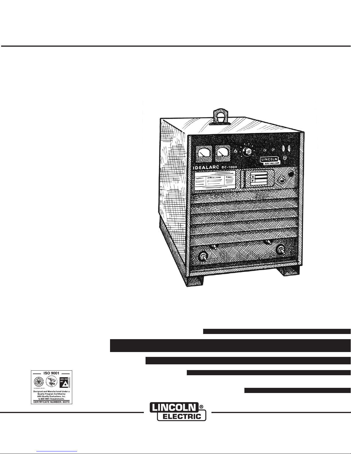
IDEALARC DC-1000
For use with machines having Code Numbers:
Safety Depends on You
Lincoln arc welding and cutting
equipment is designed and built
with saf ety in mind. Ho wever ,
your overall safety can be
increased by proper installation
... and thoughtful operation on
your part. DO NOT INSTALL,
OPERATE OR REPAIR THIS
EQUIPMENT WITHOUT READING THIS MANUAL AND THE
SAFETY PRECAUTIONS CONTAINED THROUGHOUT. And,
most importantly, think bef ore
you act and be careful.
®
§§99991199 -- 99992255,, 1100229933,, 1111330055,, 1111333300,, 1111333311,, 1111333322,, 1111333333,,
1111333344,, 1111668811 tthhrruu 1111668844
February, 2010
OPERATOR’S MANUAL
• World's Leader in Welding and Cutting Products •
• Sales and Service through Subsidiaries and Distributors Worldwide •
Cleveland, Ohio 44117-1199 U.S.A. TEL: 216.481.8100 FAX: 216.486.1751 WEB SITE: www.lincolnelectric.com
Copyright © Lincoln Global Inc.
Page 2
i
SAFETY
WARNING
CALIFORNIA PROPOSITION 65 WARNINGS
Diesel engine exhaust and some of its constituents
are known to the State of California to cause cancer, birth defects, and other reproductive harm.
The Above For Diesel Engines
ARC WELDING CAN BE HAZARDOUS. PROTECT YOURSELF AND OTHERS FROM POSSIBLE SERIOUS INJURY OR DEATH.
KEEP CHILDREN AWAY. PACEMAKER WEARERS SHOULD CONSULT WITH THEIR DOCTOR BEFORE OPERATING.
Read and understand the following safety highlights. For additional safety information, it is strongly recommended that you
purchase a copy of “Safety in Welding & Cutting - ANSI Standard Z49.1” from the American Welding Society, P.O. Box
351040, Miami, Florida 33135 or CSA Standard W117.2-1974. A Free copy of “Arc Welding Safety” booklet E205 is available
from the Lincoln Electric Company, 22801 St. Clair Avenue, Cleveland, Ohio 44117-1199.
BE SURE THAT ALL INSTALLATION, OPERATION, MAINTENANCE AND REPAIR PROCEDURES ARE
PERFORMED ONLY BY QUALIFIED INDIVIDUALS.
The engine exhaust from this product contains
chemicals known to the State of California to cause
cancer, birth defects, or other reproductive harm.
The Above For Gasoline Engines
i
FOR ENGINE
powered equipment.
1.a. Turn the engine off before troubleshooting and maintenance
work unless the maintenance work requires it to be running.
____________________________________________________
1.b. Operate engines in open, well-ventilated
areas or vent the engine exhaust fumes
outdoors.
____________________________________________________
1.c. Do not add the fue l near an open flam e
welding arc or when the engine is running.
Stop the engine and allow it to cool before
refueling to prevent spilled fuel from vaporizing on contact with hot engine parts and
igniting. Do not spill fuel when filling tank. If
fuel is spilled, wipe it up and do not start
engine until fumes have been eliminated.
____________________________________________________
1.d. Keep all equipment safety guards, covers and devices in
position and in good repair.Keep hands, hair, clothing and
tools away from V-belts, gears, fans and all other moving
parts when starting, operating or repairing equipment.
____________________________________________________
1.e. In some cases i t may b e nec essar y to remov e saf ety
gu a r d s to perf o r m r equir e d m ainten a n c e. Rem o v e
guards only when necessary and replace them when the
ma i n t e nance requ i r i ng th e ir re moval is co mplet e .
Always use the greatest care when working near moving
parts.
___________________________________________________
1.f. Do not put your hands near the engine fan.
Do not attempt to override the governor or
idler by pushing on the throttle control rods
while the engine is running.
1.h. To avoid scalding, do not remove the
radiator pressure cap when the engine is
hot.
ELECTRIC AND
MAGNETIC FIELDS
may be dangerous
2.a. Electric current flowing through a ny c onductor causes
localized Electric an d Magn et ic F ie ld s (EMF ). W el di ng
current creates E MF f ie ld s arou nd w el di ng cables and
welding machines
2.b. EMF f ie lds m ay inte rfere w ith som e pacem akers , and
welders having a pacemaker should consult their physician
before welding.
2.c. Exposure to EMF fields in welding may have other health
effects which are now not known.
2.d. All welders should use the following procedures in order to
minimize exposure to EMF fields from the welding circuit:
2.d.1.
Route the electrode and work cables together - Secure
them with tape when possible.
2.d.2. Nev er coil the electrode l ead aro und you r body.
2.d.3. Do not place your body between the electrode and
work cables. If the electrode cable is on your right
side, the work cable should also be on your right side.
___________________________________________________
1.g. To prevent accidentally starting gasoline engines while
turning the engine or welding generator during maintenance
work, disconnect the spark plug wires, distributor cap or
magneto wire as appropriate.
2.d.4. Connect the work cable to the workpiece as close as
possible to the area being welded.
2.d.5. Do not work next to welding power source.
Mar ‘95
Page 3
ii
SAFETY
ii
ELECTRIC SHOCK can
kill.
3.a. The electrode and work (or ground) circuits
are electrically “hot” when the welder is on.
Do not touch these “hot” parts with your bare
skin or wet clothing. Wear d ry , hole-free
gloves to insulate hands.
3.b. Insulate yourself from work and ground using dry insulation.
Make certain the insulation is large enough to cover your full
area of physical contact with work and ground.
In addition to the normal safety precautions, if welding
mu s t be perfo r med u nder electri c ally hazardo u s
conditions (in damp locations or while wearing wet
clothing; on metal structures such as floors, gratings or
scaffolds; when in cramped positions such as sitting,
kneeling or lying, if there is a high risk of unavoidable or
accidental contact with the workpiece or ground) use
the following equipment:
• Semiautomatic DC Constant Voltage (Wire) Welder.
• DC Manual (Stick) Welder.
• AC Welder with Reduced Voltage Control.
3.c. In semiautomatic or automatic wire welding, the electrode,
electrode reel, welding head, nozzle or semiautomatic
welding gun are also electrically “hot”.
3.d. Always be sure the work cable makes a good electrical
connection with the metal being welded. The connection
should be as close as possible to the area being welded.
3.e. Ground the work or metal to be welded to a good electrical
(earth) ground.
3.f.
Maintain the electrode holder, work clamp, welding cable and
welding machine in good, safe operating condition. Replace
damaged insulation.
3.g. Never dip the electrode in water for cooling.
3.h. Nev er simul tan eou sly t ouc h ele ctr icall y “ hot” par ts of
electrode holders connected to two welders because voltage
between the two can be the total of the open circuit voltage
of both welders.
3.i. When working above floor level, use a safety belt to protect
yourself from a fall should you get a shock.
3.j. Also see Items 6.c. and 8.
ARC RAYS can burn.
4.a. Use a shield with the proper filter and cover
plates to protect your eyes from sparks and
the rays of the arc when welding or observing
open arc welding. Headshield and filter lens
should conform to ANSI Z87. I standards.
4.b. Use suitable clothing made from durable flame-resistant
material to protect your skin and that of your helpers from
the arc rays.
4.c. Protect other nearby personnel with suitable, non-flammable
screening and/or warn them not to watch the arc nor expose
themselves to the arc rays or to hot spatter or metal.
FUMES AND GASES
can be dangerous.
5.a. Welding may produce fumes and gases
hazardous to health. Avoid breathing these
fumes and gases. When welding, k ee p
your head out of the fume. Use enough
ventilation and/or exhaust at the arc to keep
fumes and gases away from the breathing zone. When
we l ding with e lectrode s which re q uire spec i al
ve n tilati on s uch as s tainles s or ha rd f a cing (see
instru ctio ns on container or MSDS) or on lea d o r
cadmium plated steel and other metals or coatings
which produce highly toxic fumes, keep exposure as
low as possible and within applicable OSHA PEL and
ACGIH TLV limits using local exhaust or mechanical
ventilation. In confined spaces or in some circumst a nces, outd oors, a r espira tor may be r equired .
Additional precautions are also required when welding
on galvanized steel.
5. b. The operation of welding fume control equipment is affected
by various factors including proper use and positioning of
the equipment, maintenance of the equipment and the specific welding procedure and application involved. Worker
exposure level should be checked upon installation and
periodically thereafter to be certain it is within applicable
OSHA PEL and ACGIH TLV limits.
5.c.
Do not weld in locations near chlorinated hydrocarbon
coming from degreasing, cleaning or spraying operations.
The heat and rays of the arc can react with solvent vapors
form phosgene, a highly toxic gas, and other irritating products.
5.d. Shielding gases used for arc welding can displace air and
caus e injur y or deat h. Always use enough ventilati on,
especially in confined areas, to insure breathing air is safe.
vapors
to
5.e. Read and understand the manufacturer’s instructions for this
equipment and the consumables to be used, including the
ma t e r i al s a f e ty d a t a shee t (MSDS) an d fo l l o w yo u r
employer’s safety practices. MSDS forms are available from
yo u r weld i n g di s t r ibuto r or fr om th e ma n u f actur e r .
5.f. Also see item 1.b.
Jan ‘09
Page 4

iii
SAFETY
iii
WELDING and CUTTING
SPARKS can
cause fire or explosion.
6.a.
Remove fire hazards from the welding area.
If this is not possible, cover them to prevent
Re m e m b er t h a t we l d i n g s p a r ks a n d hot
materials from welding can easily go through small cracks
an d o pen i ngs to a d jac ent are as. Avo id wel ding ne ar
hydraulic lines. Have a fire extinguisher readily available.
6.b. Where compressed gases are to be used at the job site,
special precautions should be used to prevent hazardous
situations. Refer to “Safety in Welding and Cutting” (ANSI
Standard Z49.1) and the operating information for the
equipment being used.
6.c. When not welding, make certain no part of the electrode
circuit is touching the work or ground. Accidental contact
can cause overheating and create a fire hazard.
6.d. Do not heat, cut or weld tanks, drums or containers until the
proper steps have been taken to insure that such procedures
will not cause flammable or toxic vapors from substances
inside. They can cause an explosion even
been “cleaned”. For information, purchase “Recommended
Safe Practices for the
Co n t a i ners and Piping That Have Held Haza r d o u s
Substances”, AWS F4.1 from the American Welding Society
(see address above).
6.e. Vent hollow castings or containers before heating, cutting or
welding. They may explode.
Sparks and spatter are thrown from the welding arc. Wear oil
6.f.
free protective garments such as leather gloves, heavy shirt,
cuffless trousers, high shoes and a cap over your hair. Wear
ear plugs when welding out of position or in confined places.
Always wear safety glasses with side shields when in a
welding area.
6.g. Connect the work cable to the work as close to the welding
area as practical. Work cables connected to the building
framework or other locations away from the welding area
increase the possibility of t he w el di ng current passing
through lifting chains, crane cables or other alternate circuits. This can create fire hazards or overheat lifting chains
or cables until they fail.
6.h. Also see item 1.c.
the welding s pa rks fro m startin g a fire.
though
they have
Preparation
for Welding and Cutting of
CYLINDER may explode
if damaged.
7.a. Us e on ly c o m press e d ga s c y l inder s
containing the correct shielding gas for the
pr o c e s s used a n d p r operl y o p e ratin g
re g u l a tors desi g n e d fo r th e ga s an d
pressure used. All hoses, fittings, etc. should be suitable for
the application and maintained in good condition.
7.b. Alway s kee p cylin ders in an u prigh t posit ion s ecure ly
chained to an undercarriage or fixed support.
7.c. Cylinders should be located:
• Away from areas where they may be struck or subjected to
physical damage.
• A safe distance from arc welding or cutting operations and
any other source of heat, sparks, or flame.
7.d. Never allow the electrode, electrode holder or any other
electrically “hot” parts to touch a cylinder.
7.e. Keep your head and face away from the cylinder valve outlet
when opening the cylinder valve.
7.f. Valve protection caps should always be in place and hand
tight except when the cylinder is in use or connected for
use.
7.g. Rea d a nd fol low t he ins tru ctio ns on co mpr ess ed gas
cylinders, associated equipment, and CGA publication P-l,
“Precautions for Safe Handling of Compressed Gases in
Cylinders,” available from the Compressed Gas Association
1235 Jefferson Davis Highway, Arlington, VA 22202.
FOR ELECTRICALLY
powered equipment.
8.a. Turn off input power using the disconnect
switch at the fuse box before working on
the equipment.
8.b. Install equipment in a ccordance with the U.S. Nat ional
Electrical Code, all local codes and the manufac turer’s
recommendations.
8.c. Ground the equipment in accordance with the U.S. National
Electrical Code and the manufacturer’s recommendations.
6.I. Read and follow NFPA 51B “ Standard for Fire Prevention
During Welding, Cutting and Other Hot Work”, available
from NFPA, 1 Batterymarch Park, PO box 9101, Quincy, Ma
022690-9101.
6.j. Do not use a welding power source for pipe thawing.
Refer to http://www.lincolnelectric.com/safety for additional safety information.
Jan ‘09
Page 5

iv
SAFETY
iv
PRÉCAUTIONS DE SÛRETÉ
Pour votre propre protection lire et observer toutes les instructions
et les précautions de sûreté specifiques qui parraissent dans ce
manuel aussi bien que les précautions de sûreté générales suivantes:
Sûreté Pour Soudage A L’Arc
1. Protegez-vous contre la secousse électrique:
a. Les circuits à l’électrode et à la piéce sont sous tension
quand la machine à souder est en marche. Eviter toujours
tout contact entre les parties sous tension et la peau nue
ou les vétements mouillés. Porter des gants secs et sans
trous pour isoler les mains.
b. Faire trés attention de bien s’isoler de la masse quand on
soude dans des endroits humides, ou sur un plancher
metallique ou des grilles metalliques, principalement dans
les positions assis ou couché pour lesquelles une grande
partie du corps peut être en contact avec la masse.
c. Maintenir le porte-électrode, la pince de masse, le câble
de soudage et la machine à souder en bon et sûr état
defonctionnement.
d.Ne jamais plonger le porte-électrode dans l’eau pour le
refroidir.
e. Ne jamais toucher simultanément les parties sous tension
des porte-électrodes connectés à deux machines à souder
parce que la tension entre les deux pinces peut être le
total de la tension à vide des deux machines.
f. Si on utilise la machine à souder comme une source de
courant pour soudage semi-automatique, ces precautions
pour le porte-électrode s’applicuent aussi au pistolet de
soudage.
2. Dans le cas de travail au dessus du niveau du sol, se protéger
contre les chutes dans le cas ou on recoit un choc. Ne jamais
enrouler le câble-électrode autour de n’importe quelle partie
du corps.
5. Toujours porter des lunettes de sécurité dans la zone de
soudage. Utiliser des lunettes avec écrans lateraux dans les
zones où l’on pique le laitier.
6. Eloigner les matériaux inflammables ou les recouvrir afin de
prévenir tout risque d’incendie dû aux étincelles.
7. Quand on ne soude pas, poser la pince à une endroit isolé de
la masse. U n cour t- ci rcuit accidental peut provoquer un
échauffement et un risque d’incendie.
8. S’assurer que la masse est connectée le plus prés possible
de la zone de travail qu’il est pratique de le faire. Si on place
la masse sur la charpente de la construction ou d’autres
endroits éloignés de la zone de travail, on augmente le risque
de voir passer le courant de soudage par les chaines de levage, câbles de grue, ou autres circuits. Cela peut provoquer
des risques d’incendie ou d’echauffement des chaines et des
câbles jusqu’à ce qu’ils se rompent.
9. Assurer une ventilation suffisante dans la zone de soudage.
Ceci est particuliérement important pour le soudage de tôles
galvanisées plombées, ou cadmiées ou tout autre métal qui
produit des fumeés toxiques.
10. Ne pas souder en présence de vapeurs de chlore provenant
d’o pérations de d égraissage, nettoyage ou pistolage. La
chaleur ou les rayons de l’arc peuvent réagir avec les vapeurs
du solvant pour produire du phosgéne (gas fortement toxique)
ou autres produits irritants.
11. Pour obtenir de plus amples renseignements sur la sûreté,
voir le code “Code for safety in welding and cutting” CSA
Standard W 117.2-1974.
PRÉCAUTIONS DE SÛRETÉ POUR
3. Un coup d’arc peut être plus sévère qu’un coup de soliel,
donc:
a. Utiliser un bon masque avec un verre filtrant approprié
ainsi qu’un verre blanc afin de se protéger les yeux du rayonnement de l’arc et des projections quand on soude ou
quand on regarde l’arc.
b. Porter des vêtements convenables afin de protéger la
peau de soudeur et des aides contre le rayonnement de
l‘arc.
c. Proté ge r l’autre p er sonnel travaillant à p roximité au
soudage à l’aide d’écrans appropriés et non-inflammables.
4. Des gout tes de laitier en fusion sont émises de l’arc de
soudage. Se protéger avec des vêtements de protection libres
de l’huile, tels que les gants en cuir, chemise épaisse, pantalons sans revers, et chaussures montantes.
LES MACHINES À SOUDER À
TRANSFORMATEUR ET À
REDRESSEUR
1. Relier à la terre le chassis du poste conformement au code de
l’électricité et aux recommendations du fabricant. Le dispositif
de montage ou la piece à souder doit être branché à une
bonne mise à la terre.
2. Autant que possible, I’installation et l’entretien du poste seront
effectués par un électricien qualifié.
3. Avant de faires des travaux à l’interieur de poste, la debrancher à l’interrupteur à la boite de fusibles.
4. Garder tous les couvercles et dispositifs de sûreté à leur
place.
Mar. ‘93
Page 6
Thank You
ixix
for selecting a QUALITY product by Lincoln Electric. We want you
to take pride in operating this Lincoln Electric Company product
••• as much pride as we have in bringing this product to you!
The business of The Lincoln Electric Company is manufacturing and selling high quality welding equipment, consumables, and cutting equipment. Our challenge is to meet the needs of our customers and to exceed their expectations. On occasion, purchasers may ask Lincoln
Electric for advice or information about their use of our products. We respond to our customers based on the best information in our possession at that time. Lincoln Electric is not in a position to warrant or guarantee such advice, and assumes no liability, with respect to such information or advice. We expressly disclaim any warranty of any kind, including any warranty of fitness for any customer’s particular purpose,
with respect to such information or advice. As a matter of practical consideration, we also cannot assume any responsibility for updating or
correcting any such information or advice once it has been given, nor does the provision of information or advice create, expand or alter any
warranty with respect to the sale of our products.
Lincoln Electric is a responsive manufacturer, but the selection and use of specific products sold by Lincoln Electric is solely within the control
of, and remains the sole responsibility of the customer. Many variables beyond the control of Lincoln Electric affect the results obtained in
applying these types of fabrication methods and service requirements.
Subject to Change – This information is accurate to the best of our knowledge at the time of printing. Please refer to www.lincolnelectric.com
for any updated information.
CUSTOMER ASSISTANCE POLICY
Please Examine Carton and Equipment For Damage Immediately
When this equipment is shipped, title passes to the purchaser upon receipt by the carrier. Consequently, Claims
for material damaged in shipment must be made by the purchaser against the transportation company at the
time the shipment is received.
Please record your equipment identification information below for future reference. This information can be
found on your machine nameplate.
Product _________________________________________________________________________________
Model Number ___________________________________________________________________________
Code Number or Date Code_________________________________________________________________
Serial Number____________________________________________________________________________
Date Purchased___________________________________________________________________________
Where Purchased_________________________________________________________________________
Whenever you request replacement parts or information on this equipment, always supply the information you
have recorded above. The code number is especially important when identifying the correct replacement parts.
On-Line Product Registration
- Register your machine with Lincoln Electric either via fax or over the Internet.
• For faxing: Complete the form on the back of the warranty statement included in the literature packet
accompanying this machine and fax the form per the instructions printed on it.
• For On-Line Registration: Go to our
“Product Registration”. Please complete the form and submit your registration.
Read this Operators Manual completely before attempting to use this equipment. Save this manual and keep it
handy for quick reference. Pay particular attention to the safety instructions we have provided for your protection.
The level of seriousness to be applied to each is explained below:
WEB SITE at www.lincolnelectric.com. Choose “Quick Links” and then
WARNING
This statement appears where the information must be followed exactly to avoid serious personal injury or loss of life.
CAUTION
This statement appears where the information must be followed to avoid minor personal injury or damage to this equipment.
Page 7

x
Installation.......................................................................................................................Section A
Technical Specifications.......................................................................................................A-1
Safety Precautions. ..............................................................................................................A-2
Location ........................................................................................................................A-2
Stacking ........................................................................................................................A-2
Input Wiring ...................................................................................................................A-2
Reconnect Procedures ..........................................................................................A-3, A-4
Output Connections ......................................................................................................A-5
_______________________________________________________________________________
Operation.........................................................................................................................Section B
Safety Precautions ...............................................................................................................B-1
Product Description ..............................................................................................................B-1
To Set Polarity...............................................................................................................B-2
Set-Up For Various Procedures....................................................................................B-2, B-3
________________________________________________________________________________
TABLE OF CONTENTS
Page
x
Maintenance ....................................................................................................Section D
Safety Precautions ...................................................................................................D-1
General Maintenance .........................................................................................D-1
Overload Protection ...........................................................................................D-1
________________________________________________________________________
Troubleshooting..............................................................................................Section E
Safety Precautions.................................................................................................E-1
How to Use Troubleshooting Guide.......................................................................E-1
Troubleshooting Guide.............................................................................E-2 thru E-7
________________________________________________________________________
Connection and Wiring Diagrams..................................................................Section F
________________________________________________________________________
Parts List.....................................................................................................P-146 Series
________________________________________________________________________
Page 8
A-1
INSTALLATION
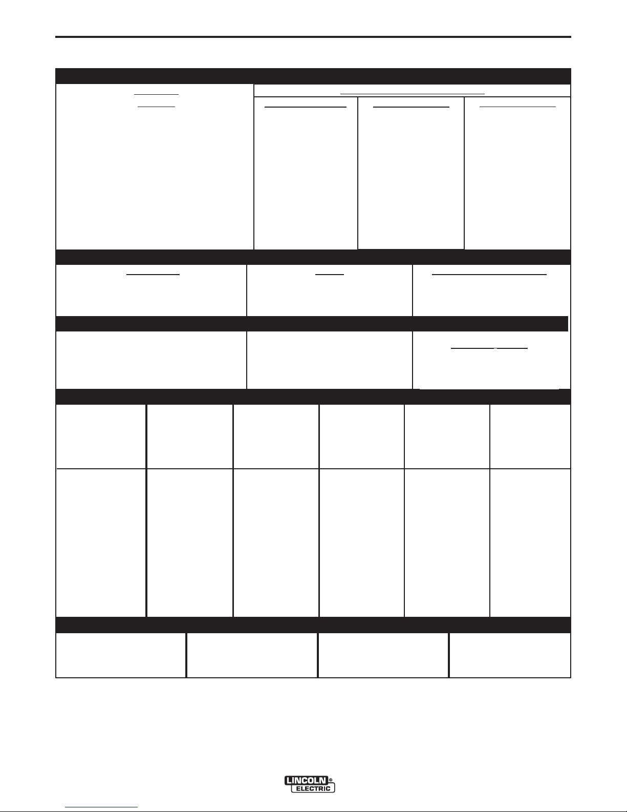
TECHNICAL SPECIFICATIONS – DC-1000
INPUT - THREE PHASE ONLY
Standard
Voltage
100% Duty Cycle
Input Current at Rated Output
60% Duty Cycle
A-1
50% Duty Cycle
220/380/440/50/60
380/500/50/60
100% Duty Cycle
60% Duty Cycle
50% Duty Cycle
Output Range
150A/16V-1300A/46V
INPUT
VOLTAGE /
FREQUENCY
230/460/60
575/60
415/50/60
Duty Cycle
193/96.5
77.2
193/112/96.5
112/85
102
215/108
86
215/124/108
124/94
113
RATED OUTPUT
Amps
1000
1140
1250
Volts at Rated Amperes
OUTPUT
Maximum Open Circuit Voltage
75V for 60 HZ models
72V for 50/60 HZ models
See the OPERATION section
information by model
RECOMMENDED INPUT WIRE AND FUSE SIZES
HERTZ
INPUT AMPERE
RATING ON
NAMEPLATE
TYPE 75°C
COPPER WIRE
IN CONDUIT
AWG(IEC-MM2) SIZES
30°C (86°F) Ambient
TYPE 75°C
GROUND WIRE
IN CONDUIT
AWG(IEC-MM2) SIZES
230/115
92
230/133/115
133/101
121
44
44
44
Auxiliary
for Auxiliary Power
Power
TYPE 75°C
(SUPER LAG)
OR BREAKER
SIZE (AMPS)
1
230
460
575
220
380
415
440
500
60
60
60
50/60
50/60
50/60
50/60
50/60
193
96.5
77.2
193
112
102
96.5
85
000 (85)
3 (27)
4 (21)
000 (85)
2 (34)
2 (34)
3 (27)
4 (21)
4 (21)
6 (14)
6 (14)
4 (21)
6 (14)
6 (14)
6 (14)
6 (14)
300 Amp
150 Amp
125 Amp
300 Amp
175 Amp
150 Amp
150 Amp
125 Amp
PHYSICAL DIMENSIONS
HEIGHT
30.75 in
781 mm
1
Also called “inverse time” or “thermal/magnetic” circuit breakers; circuit breakers which have a delay in tripping action that decreases as the magnitude of the current increases.
WIDTH
22.25 in
567 mm
IDEALARC® DC-1000
DEPTH
39.0 in
991 mm
WEIGHT
821 lbs.
372 kg.
Page 9
A-2
INSTALLATION
A-2
SAFETY PRECAUTIONS
Read this entire installation section before you
start installation.
WARNING
ELECTRIC SHOCK can kill.
• Only qualified personnel should
perform this installation.
• Turn the input power OFF at the
discon n e c t swit c h or fuse box
before working on this equipment.
Tu rn of f the input power to any
other equipment connected to the
welding system at the disconnect
switch or fuse box before working
on the equipment.
• Do not touch electrically hot parts.
• Always connect the Power Wave grounding lug
(located inside the reconnect input access door)
to a proper safety (Earth) ground.
-----------------------------------------------------------------------
LOCATION
Even though the machine is designed to operate
under a wide variety of environmental conditions, for
maximum reliability and long life the machine should
be located in a clean, dry place where there is free circulation of clean air in through the front and out the
back of the machine. Dirt and dust that can be drawn
into the machine should be kept to a minimum. Failure
to observe these precautions can result in excessive
operating temperatures and nuisance shutdown of the
machine.
The case front incorporates a recessed control panel
which protects the controls and minimizes the possibilities of accidental contact. This cover panel can be
flipped open to permit access to the enclosed control
section.
The individual case sides are removable for easy
access for internal service or inspection.
The case rear is equipped with a removable cover
plate, permitting easy access to the input panel.
The total enclosure, designed to permit outdoor operation,
resists dust, salt, rain, humidity, and high and low temperature
extremes.
The machine uses a 38” (965mm) long base. The low profile
case facilitates installation of the machine under a workbench
and stacking the machines two high to conserve floor space.
A permanent lifting eye is located at the top of the machine and
is positioned so that it acts as nearly as possible through the
center of gravity. This lift eye fits under the case of the second
machine without interference when stacking.
STACKING
WARNING
FALLING EQUIPMENT can cause
injury.
• Do not lift this machine using lift bale if
it is equipped with a heavy accessory
such as trailer or gas cylinder.
• Lift only with equipment of adequate lifting capacity.
• Be sure machine is stable when lifting.
• Do not stack more than two high.
• Do not stack the DC-1000 on top of any other
machine.
---------------------------------------------------------------------
Two DC-1000’s may be stacked by observing the following
safety precautions:
1. Make sure the first or bottom unit is setting on a level, well-
supported surface.
2. The units must be stacked with their fronts flush, making
sure the two holes in the base rails of the top unit are over
the two pins located on top of the bottom unit.
INPUT WIRING
Be sure the voltage, phase and frequency of the input power is
as specified on the welder nameplate.
Dual voltage (e.g. 230/460) models are shipped connected for
the highest voltage. To change the connection, see the connection diagram pasted to the inside of the access panel in the
case back.
Have a qualified electrician remove the rear access panel and
connect 3 phase AC power to terminals L1, L2and L3of the
input panel in accordance with the U.S. National Electrical
Code, all local codes and the wiring diagram located inside the
machine.
The welder frame must be grounded. A stud marked with the
symbol located inside the machine near the input panel is
provided for this purpose. See the U.S. National Electrical Code
for details on proper grounding methods. (See Technical
Specifications)
IDEALARC® DC-1000
Page 10
A-3
INSTALLATION
A-3
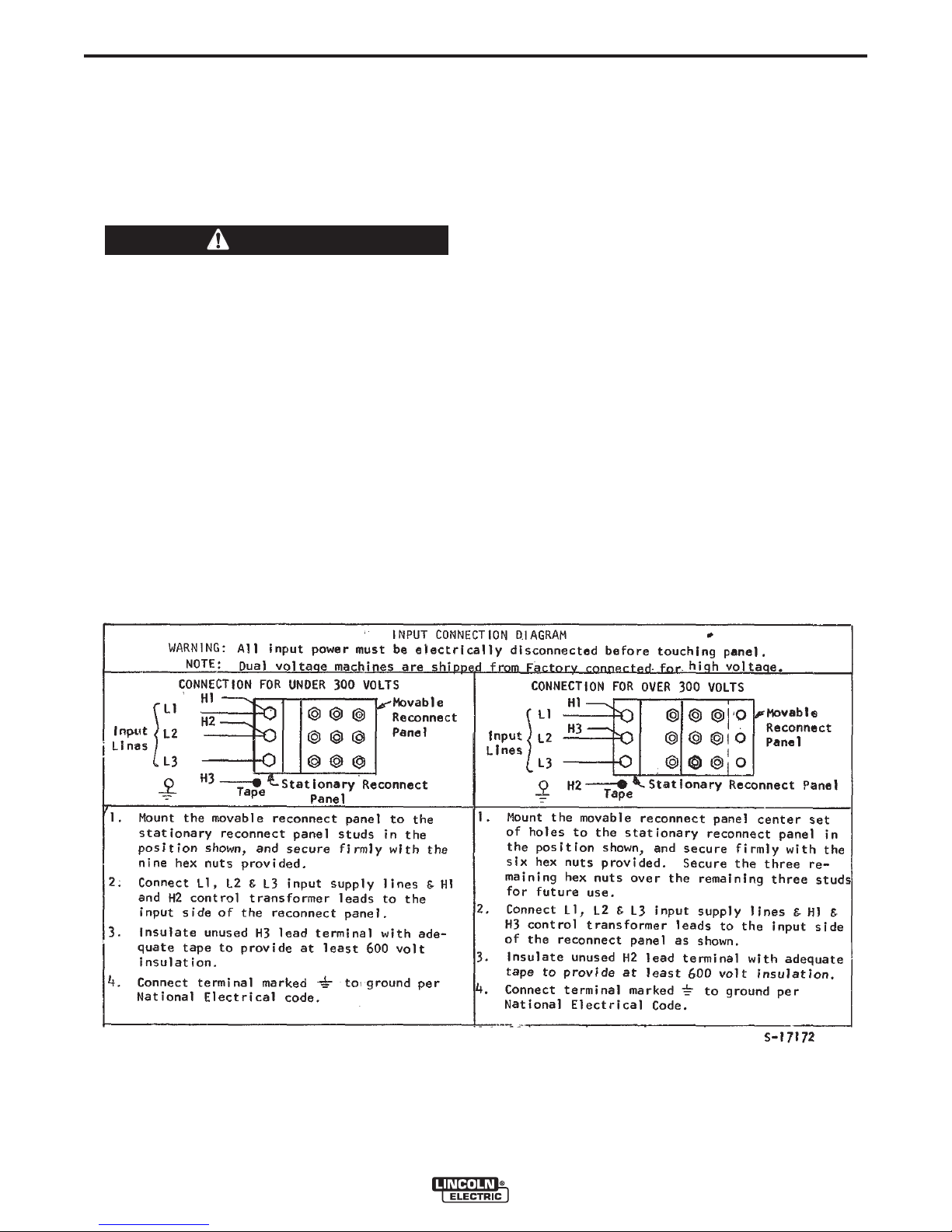
RECONNECT PROCEDURE
Multiple voltage machines are shipped connected to
the highest input voltage listed on the machine’s rating
plate. Before installing the machine, check that the
Reconnect Panel in the Input Box Assembly is connected for the proper voltage.
CAUTION
Failure to follow these instructions can cause
immediate failure of components within the
machine.
When powering welder from a generator be sure
to turn off welder first, before generator is shut
down, in order to prevent damage to the welder.
------------------------------------------------------------------------------------------------------
To reconnect a multiple voltage machine to a different
voltage, remove input power and change the position
of the reconnect board on the Reconnect Panel.
Follow The Input Connection Diagram located on the
inside of Case Back Input Access Door. These connection diagrams for the following codes are listed
below.
1. For Single and Dual Voltage except 380/500 see
Figure 1, (S17172).
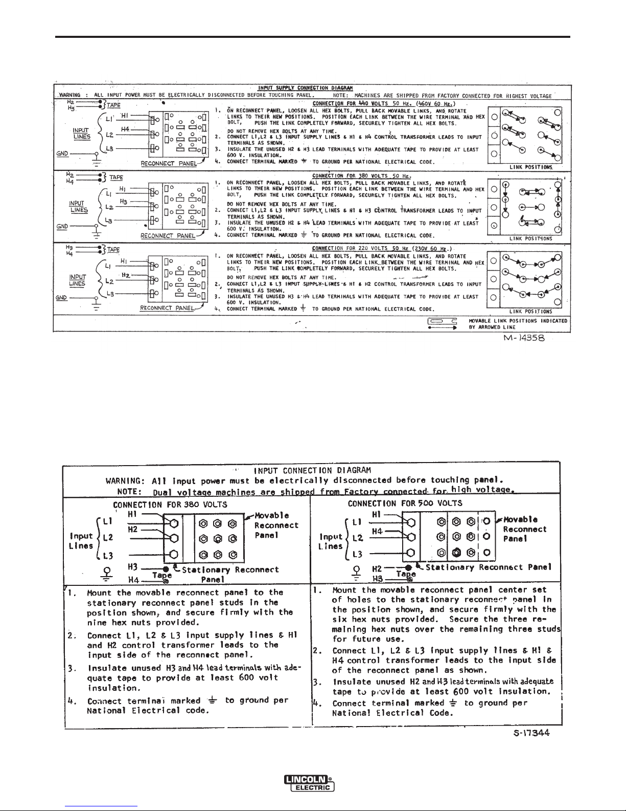
2. For 220/380/460, see Figure 2, (M14358).
3. For 380/500, see Figure 3, (S17344).
4. For Voltages not listed, see the Input Connection
Diagra m p a s ted on th e i n side of th e C a se
Back Input Access Door.
FIGURE 1
IDEALARC® DC-1000
Page 11
A-4
INSTALLATION
FIGURE 2
A-4
FIGURE 3
IDEALARC® DC-1000
Page 12

A-5
INSTALLATION
A-5
OUTPUT CONNECTIONS
Output Studs
The output leads are connected to the output terminals. The output terminals are located on the lower
case front and labeled “+” and “-”. There are 1000
amp rated “+” terminals on the right side, one 500
amp rated “+” terminal near the center and “-” terminals on the left side. They are fully recessed to minimize the possibility of accidental contact by an object
or a person. Strain relief is provided by the oval holes
in the base. The leads are run through these oval
holes before they are connected to the output terminals.
The 1000 amp output connections provide the full
rated output range of the machine. See Table1 for
recommended DC-1000 cable sizes for combined
lengths of electrode and work cables.
The 500 amp output connections provide enhanced
lower current arc characteristics, especially for submerged arc and GMAW procedures below 450 amps.
Auxiliary Power
This machine supplies the 115 volt, AC power needed
for operating wire feeding equipment. The power is
available from terminals #31 and #32 on the terminal
strip. An 8 amp slow blow fuse on the machine control
panel protects the auxiliary power from excessive
overloads. The circuit has a 1000 volt-ampere rating.
Control Cable Connection
Terminal strips with screw connections are located
behind the hinged door on the front of the power
source to make all the control cable connections for
operating wire feeding equipment. See the appropriate connection diagram for exact instructions covering
the wire feeder being used.
With the DC-1000 turned off, the control cable from
the automatic wire feeding equipment is connected to
the terminal strip. A strain relief box connector is provided for access into the terminal strip section. A
chassis grounding screw is also provided below the
terminal strip marked with the symbol for connecting the wire feeding equipment grounding wire. See
the appropriate connection diagram for the exact
instructions for the wire feeder being used. A spare
hole is provided for an additional box connector if
required.
Connecting for Air Carbon Arc:
a. Turn off all power.
b. Disconnect all wire feed unit control, electrode and
work leads.
c. Connect a jumper from 2-4 on terminal strip.
d. Place mode switch in the CV(I) position.
With the DC-1000 connected for air carbon arc welding, the output terminals will be energized at all times.
DC-1000 Cable Sizes for Combined Lengths of Copper Electrode and Work Cable
ELECTRODE, WORK AND #21 LEAD
Lengths up to 150 ft. (46m)
TABLE 1
at 100% Duty Cycle
3
3
IDEALARC® DC-1000
Cable SizeParallel CablesCable Length
1/0 (53mm
2/0 (67mm
3/0 (85mm
2
)3
2
)150 ft.(46m) to 200 ft (61m)
2
)200 ft.(61m) to 250 ft.(76m)
Page 13

B-1
OPERATION
B-1
OPERATING INSTRUCTIONS
WARNING
ELECTRIC SHOCK can kill.
• Do not touch electrically live parts or
electrode with skin or wet clothing.
• Insulate yourself from wor k an d
ground.
• Always wear dry insulating gloves.
------------------------------------------------------------------------
FUMES AND GASES can be danger-
ous.
• Keep your head out of fumes.
• Use ventilation or exhaust to remove
fumes from breathing zone.
------------------------------------------------------------------------
WELDING SPARKS can cause fire or
explosion.
• Keep flammable material away.
• Do not weld on closed containers.
------------------------------------------------------------------------
ARC RAYS can burn eyes and skin.
• Wear eye, ear and body
protection.
NOTE: All P.C. boards are protected by a moisture
resistant coating. When the welder is operated, this
coating will “bake off” of certain power resistors that
normally operate at high temperatures emitting some
smoke and odor for a short time. These resistors and
the P.C. board beneath them may become blackened.
This is a normal occurrence and does not damage the
component or affect the machine performance.
TO SET POLARITY
Turn off the DC-1000 and connect the electrode cable
to the “Positive” or “Negative” studs depending upon
the electrode polarity desired. Connect the work cable
to the other stud. (See “Output Connections”).
Set the “Electrode Negative-Electrode Positive” switch
to correspond to the polarity of the electrode cable
connection. This switch setting is necessary for proper
operation of some Lincoln wire feeders and does not
change the welding polarity.
Starting the Machine - The push button power “on”
switch at the extreme right side of the control panel
energizes and closes the three phase input contactor
from a 115 volt auxiliary transformer. This in turn energizes the main power transformer.
------------------------------------------------------------
See additional warning information at
front of this operator’s manual.
-----------------------------------------------------------
PRODUCT DESCRIPTION
The DC-1000 is an SCR-controlled three phase DC
power source. It is designed with a single range
potentiometer control for submerged arc or open arc
automatic and semiautomatic welding. It can be used
for air carbon arc cutting with carbon rods up to and
including 5/8” (15.9mm) dia. The DC-1000 (below
code 9500) is not recommended for stick welding or
for solid wire and gas in the short arc welding mode.
With the addition of the 500 amp output stud to DC1000 models above code 9500, GMAW procedures
can be performed. This connectio n provides the
enhanced lower current arc characteristics required
for this type of welding.
The DC-1000 is provided with a three position mode
switch that selects CV Innershield®, CV Submerged
Arc or CC (Variable Voltage) Submerged Arc.
The unit is designed to be used with the NA-5, NA-5R
and NA-3 automatics, the LT-56 and LT-7 tractors,
and can also be used with the LN-7, LN-8 or LN-9
semiautomatic wire feeders.
The red light below the stop-start button indicates
when the input contactor is energized.
Output Control - The output control in the center of
th e contro l panel is a c o ntinuou s contro l of th e
machine output. The control may be rotated from min.
to max. while under load to adjust the machine output.
The machine is equipped with line voltage compensation as a standard feature. This will hold the output relatively constant except at maximum output of the
machine, through a fluctuation of +/- 10% of input line
voltage.
Output Control at DC-1000 or Ou tput Control
Remote Switch
The toggle switch on the control panel labeled “Output
Control at DC-1000” / “Output Control Remote” gives
the operator the option of controlling the output at the
machine control panel or at a remote station. For
remote control, the toggle switch is set in the “Output
Control Remote” position and controlled at the wire
feed unit control or by connecting a K775 control to
the appropriate terminals (as indicated on the connection diagram) on the terminal strip at the front of the
machine. For control at the machine control panel, the
toggle switch is set in the “Output Control at DC-1000”
position.
IDEALARC® DC-1000
Page 14

B-2
INSTALLATION
B-2
Remote Output Control - (Optional)
The K775 Remote Output Control consists of a control
box with 28 ft. (8.4m) of four conductor cable. This
connects to terminals 75, 76, 77 on the terminal strip,
and the case grounding screw so marked with the
symbol on the machine. These terminals are
made available by opening the terminal access cover
on the left side of the case front. This control will give
the sa m e con t r o l as th e outp u t con t r o l on t h e
machine.
Mode Switch
The toggle switch labeled C (I) Innershield, CV(S)
Submerged Arc, CC (or Variable Voltage) is used to
sel e ct the p r oper weld e r charac t e ristics f o r the
process being used. The CC (or Variable Voltage)
mode is primarily available for use with older wire
feeding equipment such as the LAF-3, LT-34 and so
forth. Use of this type of older equipment requires the
addition of an NL Option Kit.
SET-UP FOR VARIOUS PROCEDURES
1. Selection of mode switch position - There are
several general rules to follow in the selection of
the mode switch position.
NOTE: Some processes and procedures may be better with the mode switch in the other CV position. If
the mode switch position initially selected is not producing the desired results, then place the mode switch
in the other CV position and make a test weld. Then
us e the CV mode switch posit ion t hat gives the
desired results.
2. NA-3 - The NA-3 should be set for the mode being
used on the power source. If using either of the
CV modes, the NA-3 CC board switch should be
set for CV. If the power source is used in the CC
mode, then the NA-3 CC board mode switch
should be placed in the CC position.
All the NA-3’s when used with the DC-1000 are capable of cold starting with the constant current board
mode switch in CC. Cold starting permits the wire to
be inched down to the work, automatically stop, and
automatically energize the flux hopper valve. All NA3’s made after September, 1976 are capable of cold
starting on either CV or CC settings of the constant
current board.
On the NA-3, set the open circuit voltage control to the
same dial setting as the arc voltage control. If the procedure has not yet been established, a good starting
point is to set the OCV to #6.
a. Use the CV(I) mode for all FCAW and GMAW
processes. The CV(I) mode is also used for
air carbon arc using carbon rods up to and
including 5/8” (15.9mm) dia.
Welding with NR®-151, 202, 203 and other
electrodes below 20 volts, is not recommended.
b. Use the CV(S) mode for all submerged arc
welding. This applies to both low and high
travel speeds.
c. The CC (Variable Voltage) mode is available
for high current large puddle submerged arc
procedures that cannot be done as well with
the constant voltage mode. CC mode should
be used for 3/16” (4.8mm) diameter electrode
and above where high current surges cause
machine shutdown when starting. This occurs
primarily when the slag ball is not cut from the
electrode prior to starting. (Also requires a
wire feeder that has a constant current mode
- i.e. NA-3S).
Run a test weld, setting the proper current, voltage
and travel speed. Once the proper welding procedure
is established and if the start is poor - wire blast off,
stub, etc. - adjust the NA-3 OCV and inch speed controls for optimum starting. In general, a low inch speed
and an OCV dial setting identical to the voltage dial
setting will provide the best starting.
To further optimize starting, adjust the OCV by making
repeated starts and observing the NA-3 voltmeter
action. With proper adjustment of the OCV control, the
voltmeter needle will swing smoothly up to the desired
arc voltage and thus provide repeatable starts.
If the voltmeter swings above the set voltage and then
back to the desired welding voltage, the OCV setting
is too high. This usually results in a bad start where
the wire tends to “blast off”.
If the voltmeter needle hesitates before coming up to
the desired voltage, the OCV is set too low. This will
cause the electrode to stub.
IDEALARC® DC-1000
Page 15

B-3
3. NA-5 - Set th e DC-10 00 mode switch to the
process being used - CV(I) Innershield or CV(S)
Sub Arc. Set the DC-1000 machine/remote switch
in the remote position. Set the OCV control four
volts higher than the welding voltage and the inch
speed at 1/2 the welding wire feed speed for the
initial test weld. Adjust the OCV and inch speed as
required for optimum starting. Refer to the NA-5
instruction manual for data regarding the setup of
controls and modes on the NA-5.
4. LN-8 - Set the LN-8 mode switch (located on the
CC board) to the CV position. Set the DC-1000
mode switch on CV(I) Innershield or CV(S) Sub
Arc according to the process being used.
5. LN-7, LN-9 and other constant wire feed units Set the DC-1000 mode switch on CV(I) Innershield
or CV(S) Sub Arc according to the process being
used. If using an LN-9, refer to the LN-9 instruction
manual for further instructions on its use. If using
an LN-7, it will be necessary to use either a K775
Remote Control or operate the DC-1000 with the
machine/remote switch in the machine position.
INSTALLATION
B-3
NL Option Kit (Not Required with NA-3, NA-5, LT-7
or LT-56).
The K783 NL Option Kit (for field installation) is
designed to permit use of the obsolete NA-2, LAF-3,
LT-3 and LT-3 section of the LT-34 tractor. It provides
the necessary DC control power for the operation of
the equipment and the necessary circuitry for proper
inching, cold starting and arc striking. In using the NL
Option Kit, a K775 remote field control is required and
is included as part of the kit. Installation instructions
are included with the NL Option Kit.
IDEALARC® DC-1000
Page 16

D-1
MAINTENANCE
D-1
SAFETY PRECAUTIONS
WARNING
ELECTRIC SHOCK can kill.
• Only qual i f i ed p e rsonnel sh o u l d
perform this installation.
• Turn the i n p u t power OF F a t the
disconnect switch or fuse box before
working on this equipment.
• Do not touch electrically hot parts.
------------------------------------------------------------------------
GENERAL MAINTENANCE
1. The f an motor s have se aled bear i ngs whic h
require no service.
2. In extremely dusty locations, dirt may clog the air
channels causing the welder to run hot. Blow out
the welder with low pressure air at regular intervals as required to eliminate excessive dirt and
dust buildup on internal parts.
OVERLOAD PROTECTION
The control board is designed with adequate protection so that no damage will occur if the remote control
leads are shorted together or are grounded to the
case. The machine will automatically shut down if
such faults do occur.
An 8-amp fuse located on the machine control panel
protects the 115 volt auxiliary AC circuit (#31 and #32)
from overload. If replacing, use the same type and
size fuse.
The power source is thermostatically protected with
two proximity thermostats against overload or insufficient cooling. One thermostat is located on the transformer secondary Negative Output Lead, and the
other thermostat is located on the choke coil. The
thermostats are connected in series in the machine
control circuit so that if an excessive overload is
applied to the machine, or the machine should receive
insufficient cooling on either the main transformer,
SCR bridge assembly or choke, the input contactor
would open and remain open until the machine cools.
It can then be manually restarted by operating the
start push button.
The power source is also protected against heavy
overloads on the SCR bridge assembly through an
electronic protection circuit. This circuit senses an
overload on the power source and opens the input
contactor should the overload remain for a predetermined time. The predetermined time varies with the
amount of overload; the greater the overload, the
shorter the time. The input contactor will remain open
until the power source is manually started with the
start push button.
IDEALARC® DC-1000
Page 17

E-1
TROUBLESHOOTING
HOW TO USE TROUBLESHOOTING GUIDE
WARNING
Service and Repair should only be performed by Lincoln Electric Factory Trained Personnel.
Unauthorized repairs performed on this equipment may result in danger to the technician and
machine operator and will invalidate your factory warranty. For your safety and to avoid Electrical
Shock, please observe all safety notes and precautions detailed throughout this manual.
__________________________________________________________________________
E-1
This Troubleshooting Guide is provided to help you
locate and repair possible machine malfunctions.
Simply follow the three-step procedure listed below.
Step 1. LOCATE PROBLEM (SYMPTOM).
Look under the column labeled “PROBLEM (SYMPTOMS)”. This column describes possible symptoms
that the machine may exhibit. Find the listing that
best describes the symptom that the machine is
exhibiting.
Step 2. POSSIBLE CAUSE.
The second column labeled “POSSIBLE CAUSE” lists
the obvious external possibilities that may contribute
to the machine symptom.
Step 3. RECOMMENDED COURSE OF ACTION
This column prov ides a course of ac tion for the
Possible Cause, generally it states to contact your
local Lincoln Authorized Field Service Facility.
If you do not understand or are unable to perform the
Recommended Course of Action safely, contact your
local Lincoln Authorized Field Service Facility.
If for any reason you do not understand the test procedures or are unable to perform the tests/repairs safely, contact your
Local Lincoln Authorized Field Service Facility for technical troubleshooting assistance before you proceed.
CAUTION
IDEALARC® DC-1000
Page 18

E-2
Observe all Safety Guidelines detailed throughout this manual
PROBLEMS
(SYMPTOMS)
TROUBLESHOOTING
POSSIBLE
CAUSE
E-2
RECOMMENDED
COURSE OF ACTION
Input contactor (1CR) chatters.
Machine input contactor does not operate.
Input contactor pulls in when start button
is pressed, but immediately drops out.
1. Faulty input contactor (1CR).
2. Low line voltage.
3. Faulty 2CR relay.
1. Supply line fuse blown.
2. Contactor power circuit dead.
3. Broken power lead.
4. Wrong input voltage.
5. Secondary or choke thermostat open.
6. Open input contactor coil.
7. Faulty stop/start push button switch.
8. Faulty 2CR relay.
9. Defective control board.
1. Defective start/stop push button.
2. Defective 1CR interlock.
3. Ground fault between control terminals 73, 74, 75, 76 or 77 and negative output terminal.
4. Short on output terminals with 2-4
jumpered.
5. Defective control board.
1. Repair or replace.
2. Check input power.
3. Repair relay.
1. Replace if blown - look for reason
first.
2. Check pilot transformer T2 and associated leads.
3. Check input voltage at contactor.
4. Check voltage against instructions.
5. Check for overheating; make sure fan
is operating and there is no obstruction to free air flow. Replace faulty
thermostat.
6. Replace coil.
7. Replace switch.
8. Replace relay.
9. Replace control board. See P.C.
board troubleshooting guide.
1. Check and replace if necessary.
2. Repair or replace.
3. Check 73, 74, 75, 76 or 77 for ground
to negative output circuit.
4. Remove short.
5. Replace control board. See P.C.
board troubleshooting guide.
Machine input contactor operates but no
output when trying to weld.
1. Electrode or work lead loose or broken.
2. Open main transformer (T1) primary
or secondary circuit.
3. Output pilot relay 4CR not operating
or faulty.
4. Firing circuit P.C. board not connected or is faulty.
5. If using 500 amp stud, choke circuit
may be open.
1. Repair connection.
2. Repair.
3. Check relay pull-in by connecting a
jumper across terminals 2 and 4 on
DC-1000 terminal strip. Replace if
faulty.
4. All nine light emitting diodes (LED1
thru LED9) must be lit. See P.C.
board troubleshooting guide.
5. Repair.
CAUTION
If for any reason you do not understand the test procedures or are unable to perform the tests/repairs safely, contact your
Local Lincoln Authorized Field Service Facility for technical troubleshooting assistance before you proceed.
IDEALARC® DC-1000
Page 19

E-3
PROBLEMS
(SYMPTOMS)
TROUBLESHOOTING
Observe all Safety Guidelines detailed throughout this manual
POSSIBLE
CAUSE
RECOMMENDED
COURSE OF ACTION
E-3
Machine has maximum output but
not control.
Machine has minimum output and no
control.
Machine does not have maximum
output.
Machine has output but trips off
immediately when wire feed unit
start button is pressed.
1. Output control switch (SW3) in wrong
position.
2. Output control switch faulty.
3. Open in feedback circuitry.
4. Faulty control or firing circuit P.C.
boards.
5. Output control potentiometer circuit
open (Lead 75).
1. Terminals 73, 74, 75, 76 or 77
grounded to positive output.
1. One input fuse blown.
2. One phase of main transformer open.
3. Faulty control or firing circuit P.C.
boards.
4. Output control potentiometer defective.
5. Output control potentiometer leads
open - 76, 77, 226, 236, 237, 238.
1. Check position of switch.
2. Check switch and replace if faulty.
3. Check wiring and control and firing
circuit P.C. board wiring harness
plugs.
4. All light emitting diodes must be lit,
except LED4 on the control/fault
board. See P.C. board troubleshooting guide.
5. Check and replace potentiometer if
faulty. Check wiring of Lead #75.
1. Check 73, 74, 75, 76 or 77 for ground
to positive output circuit.
1. Check and replace if blown after
checking for reason for blown fuse.
2. Check for open and repair.
3. All light emitting diodes must be lit on
both P.C. boards, except LED4 on
control/fault board. See P.C. board
troubleshooting guide.
4. Check and replace if faulty.
5. Repair.
Variable or sluggish welding arc.
Machine will not shut off.
Output control not functioning on the
(1)
machine
(1)
If connected to an LN-9 or NA-5, disconnect leads 73, 74, 75 before troubleshooting.
.
1. Machine has either an internal or
external short circuit on the output.
2. Faulty control P.C. board.
3. Terminals 73, 74, 75, 76, 77 grounded to negative output terminal.
1. Poor work or electrode connection.
2. Welding leads too small.
3. Welding current or voltage too low.
4. Defective main SCR bridge.
1. Input contactor contacts frozen.
2. Faulty 2CR relay.
1. Check internally and externally for
any shorts and remove or repair.
2. Replace control board. See P.C.
board troubleshooting guide.
3. Check for grounded 73, 74, 75, 76,
77.
1. Check and clean all connections.
2. Check table in instruction manual.
3. Check procedures for recommended
settings.
4. Check and replace if defective.
1. Check and replace if necessary.
2. Check and replace if necessary.
CAUTION
If for any reason you do not understand the test procedures or are unable to perform the tests/repairs safely, contact your
Local Lincoln Authorized Field Service Facility for technical troubleshooting assistance before you proceed.
IDEALARC® DC-1000
Page 20

E-4
PROBLEMS
(SYMPTOMS)
TROUBLESHOOTING
Observe all Safety Guidelines detailed throughout this manual
POSSIBLE
CAUSE
RECOMMENDED
COURSE OF ACTION
E-4
Output control not functioning on remote
control.
Poor starting on CV(S) Sub-Arc.
Poor bead shape or erratic arc on CV(S)
Sub-Arc.
1. Output control switch in wrong position.
2. Faulty output control switch.
3. Faulty remote control potentiometer.
4. Leads or connections open in control
circuit.
5. Faulty firing or control circuit P.C.
board.
1. Improper procedures or setting of
controls.
2. Poor electrode or work connection.
3 3CR reed switch inoperative.
4 Faulty control board.
1. Improper procedures.
2. Defective 3CR reed switch.
3. Faulty control board.
4. Defective main SCR bridge.
1. Place switch in “Output Control
Remote”.
2. Check and replace if found faulty.
3. Check and replace if found faulty.
(Voltage from 75 to 77 should be 3 to
5V).
4. Check all leads and connections,
internal or remote, for continuity;
repair if necessary.
5. All light emitting diodes must be lit on
both P.C. boards, except LED4 on
control/fault board. See P.C. board
troubleshooting guide.
1. See instruction manual and procedures.
2. Repair connections.
3. Check reed switch voltage leads 216
to 220. Idle voltage is about 8V; when
welding, voltage must go to zero.
4. Replace. See P.C. board troubleshooting guide.
1. See instruction manual and procedures.
2. Check reed switch per item c. of previous Table above.
3. Replace. See P.C. board troubleshooting guide.
4. Check and replace if defective.
Poor starting on CV(I) Innershield and
CV(S) Sub-Arc.
Poor arc characteristics on CV(I)
Innershield or other open arc processes.
Poor arc characteristics on all processes.
Poor performance (including arc outages) while welding at low current (less
than 450 amps) when connected to 1000
amp “+” output studs.
Machine frequently shuts off while using
the 500 amp “+” output stud.
1. Defective 3CR reed switch.
2. Faulty control board.
1. Mode switch in CV(S) Sub-Arc mode.
2. Defective main SCR bridge.
1. Defective control board.
2. Defective firing board.
3. Defective main SCR bridge.
1. Insufficient output inductance.
1. Effective current demand well over
500 amperes.
1. Replace.
2. Replace.
1. Place mode switch in CV(I)
Innershield mode.
2. Check and replace if defective.
1. Check and replace if defective. See
P.C. board troubleshooting guide.
2. Check and replace if defective. See
P.C. board troubleshooting guide.
3. Check and replace if defective.
1. Use the 500 amp “+” output stud.
1. Use the 1000 amp “+” output studs.
CAUTION
If for any reason you do not understand the test procedures or are unable to perform the tests/repairs safely, contact your
Local Lincoln Authorized Field Service Facility for technical troubleshooting assistance before you proceed.
IDEALARC® DC-1000
Page 21

E-5
Observe all Safety Guidelines detailed throughout this manual
TROUBLESHOOTING
P.C. BOARD TROUBLESHOOTING GUIDE
WARNING
ELECTRIC SHOCK can kill.
• Have an electrician install and service
this equipment.
• Turn the input power off at the fuse
box before working on equipment.
• Do not touch electrically hot parts.
---------------------------------------------------------------------
Machine settings for P.C. board troubleshooting.
Disconnect all leads to the wire feeder and jumper terminals #2 and #4 on DC-1000. Output Control at DC-
1000. Mode switch in the CV(I) position.
CON TROL/FAULT PR OTE CTI ON P.C.
BOARD
1. LED1 indicates AC input voltage is present at pins
255-256. If not lit, check the voltage across the
secondary winding of the control transformer, T2.
The voltage should be approximately 115 volts. If
not, the problem is in the power supply and not the
P.C. board.
E-5
1. Lights 7, 8, and 9 indicate AC power being supplied to the P.C. boards from T1 auxiliary winding.
If a light is not lit, turn the machine off and unplug
P5 from J5 on the firing P.C. board. Turn the
machine on and check the following voltages:
Light That Check AC Voltage Voltage Should
Was Off Between Pins of Be Approx.
Plug P5
7 P5 Pins 2 & 4 75 VAC
(Wires 203, 204)
8 P5 Pins 7 & 3 75 VAC
(Wires 205, 206)
9 P5 Pins 9 & 8 75 VAC
(Wires 207, 208)
• If appr oxima tely 75 VA C is present, turn the
machine off, plug P5 back into firing board. Turn
the machine back on and check to see if the light
or lights are on. If the light or lights are not on
replace the firing P.C. board.
• If the 75 VAC was not present, then check the
wiring.
2. LED2 indicates welder output voltage is being supplied to the control circuit. If not lit, check to make
certain lead 222 from pin 2 of the 15-pin control
circuit P.C. board connector is connected to the
power source negative output lead and is not broken.
3. LED3 indicates power is being applied to fault protection pilot relay 2CR to turn on the input contactor.
4. LED4 indicates when overcurrent protection circuit
is being activated.
5. LED5 indicates a control signal is being supplied
to the firing circuit. As the output control is varied,
LED5 should change brilliancy from bright at low
output to dim at high output.
FIRING CIRCUIT P.C. BOARD
All nine light emitting diodes must be lit when the
power source is turned on and the wire feed arc start
button is pressed or a jumper is connected between 2
and 4.
2. Lights 1 through 6 indicate gate signals are being
supplied to the main power SCR’s 1 through 6
respectively. If light 5 on the control circuit and
lights 7 through 9 on the firing circuit are lit and
lights 1 through 6 are not lit, check lead 231
between the firing circuit and the control circuit
that it is not broken and is connected to each
Molex connector. If the lead shows continuity and
lights 1 through 6 are not lit, replace the firing circuit P.C. board. If any one of the lights 1 through 6
is not lit and lights 7 through 9 are lit, replace the
firing circuit P.C. board.
If for any reason you do not understand the test procedures or are unable to perform the tests/repairs safely, contact your
Local Lincoln Authorized Field Service Facility for technical troubleshooting assistance before you proceed.
CAUTION
IDEALARC® DC-1000
Page 22

E-6
Observe all Safety Guidelines detailed throughout this manual
TROUBLESHOOTING
PRO CED URE F OR RE PLA CIN G P.C .
BOARDS
When P.C. board is to be replaced, the following procedure must be followed:
1. Visually inspect P.C. board in question. Are any of
the components damaged? Is a conductor on the
back side of the board damaged? All P.C. boards
are protected by a moisture resistant coating.
When the welder is operated, this coating will
“bake off” of certain power resistors that normally
ope r ate at h igh tempe ratures e m itting so me
smoke and odor for a short time. These resistors
and the P.C. board beneath them may become
blackened. This is a normal occurrence and does
not damage the component or affect the machine
performance.
a. If there is no damage to the P.C. board, insert
a new one and see if this remedies the problem. If the problem is remedied, replace the
old P.C. board and see if the problem still
exists with the old P.C. board.
E-6
1) If the problem is no longer present with the
old board, check the P.C. board harness
plug and P.C. board plug for corrosion,
contamination, or oversize.
2) Check leads in the harness for loose connections.
b. If there is damage to the P.C. board, refer to
the Troubleshooting Guide
If for any reason you do not understand the test procedures or are unable to perform the tests/repairs safely, contact your
Local Lincoln Authorized Field Service Facility for technical troubleshooting assistance before you proceed.
CAUTION
IDEALARC® DC-1000
Page 23

E-7
TROUBLESHOOTING
OUTLINE FOR DC-1000 TROUBLESHOOTING GUIDE
If troubleshooting guide indicates a possible P.C.
board problem, the following guide can be used to
locate the problem.
NO WELDER OUTPUT (INPUT CONTACTOR “ON”. 2 AND 4 CLOSED)
CHECK CONTROL BOARD
E-7
LED5
IF OFF
CHECK LED1
IF OFF IF ON
CHECK AC REPLACE
INPUT TO CONTROL
CONTROL BOARD
BOARD -
POSSIBLE
DEFECTIVE
T2 TRANSFORMER
MACHINE HAS OUTPUT
(Jumper 2-4) BUT TRIPS
OFF IMMEDIATELY
CHECK FOR SHORT CHECK LEADS
BETWEEN ELECTRODE AND 73, 74, 75, 76, 77 FOR
WORK LEADS, REMOVE GROUND TO
EXTERNAL LEADS FROM NEGATIVE OUTPUT
THE OUTPUT TERMINALS TERMINAL
CHECK GATE LEAD CHECK LIGHTS
CHECK FIRING BOARD
IF YES IF NO
CONNECTIONS 7,8,9
TO SCR’S
IF ON
LED’S
ALL
NINE LIGHTS
SHOULD
BE ON
IF ONE IF ON AND
OR MORE OTHER LIGHTS
ARE OUT ARE OUT
CHECK AC INPUT
TO BOARD, REPLACE
203-204, 205-206 FIRING
207-208 -- POSSIBLE BOARD
DEFECTIVE
AUXILIARY
WINDINGS ON MAIN
TRANSFORMER
CHECK FOR OPEN
IN LEADS 203, 204
205, 206, 207, 208
IF TROUBLE STILL PERSISTS,
CHECK LED 3 ON
CONTROL BOARD
IF LIGHT GOES ON, THEN
QUICKLY OUT WHEN START
BUTTON IS PRESSED,
CONTROL BOARD IS
DEFECTIVE AND SHOULD
BE REPLACED
If for any reason you do not understand the test procedures or are unable to perform the tests/repairs safely, contact your
Local Lincoln Authorized Field Service Facility for technical troubleshooting assistance before you proceed.
ERRATIC WELDING
CHECK PROCEDURE
CHECK MODE SWITCH FOR PROPER POSITION FOR
PROCESS BEING USED
CHECK LED’S 1 THRU 6 FOR EQUAL BRILLIANCY
IF LIGHTS ARE NOT ALL APPROXIMATELY EQUALLY
BRIGHT, REPLACE FIRING P.C. BOARD
CAUTION
IDEALARC® DC-1000
Page 24

F-1
82
21 4
2
31
32
7
7
76
7
574
73
672142
3
132
75 76
77
N.C.
POWER SOURCE
N
.B.
N.A.
NEGATIVE
POSITIVE
N.D.
TO WORK
ELECTRODE CABLE TO
A
UTOMATIC EQUIPMENT
35 VOLT CONTROL
EXCITER
2
1
1
6
421
10
21
3
2
3
1
18
45 29
5
TAPE UP LEADS
NOT USED
K775 REMOTE CONTROL
M
OUNTED AT LAF-3
T
O LAF-3
CONTROL BOX
CONNECT THE RED LEAD TO
T
ERMINAL 22
75
76
77
75
76
77
G
ND
22
3
1
32
2
1
10
1
2
4
N
L OPTION
1
0
6
E
D
F
C
21
42
31
32
73
74
75
76
77
4
G N D
P
OWER SOURCE
NEGAT IVE
POSITIVE
21
N.A.
ELECTR ODE CA BL E TO
TO WORK
}
TO LN-8 IN PUT
CABLE PLUG
CONTROL CABLE
32
31
2
C
B
A
}
*
WIRE FEED UNIT
N.D.
N.B. &
N.C.
M13321
8-2-90F
DIAGRAMS
CONNECTION OF DC-1000 WITH NL OPTION KIT TO LAF-3 (Obsolete)
F-1
N.A. On all DC-1000 and DC-1500 units
with codes above 8234 extend lead
67 and connect it to the electrode
cable going to the automatic equipment.
N.B. On DC-1500 units below code 8234
this is 67 and the LAF-3 #67 lead can
be connected either to the #67 terminal or the electrode cable terminal as
shown. Terminal 82 not present on
later D.C. 1500’s and all DC-1000’s.
N.C. Terminals 73 and 74 not present on
earlier DC-1500’s.
CONNECTION OF DC-1000 TO LN-8
S17176
8-2-90F
N.D. Alternative 500 amp positive terminal
connection provided on DC-1000
models above code 9500 only.
This diagram shows the electrode connected positive. To change polarity, turn power
source off, reverse the electrode and work
leads at the power source and position the
switch on the power source and NL Option
Kit to the proper polarity. Also reverse the
leads on the back of the ammeter and voltmeter in the LAF-3 control box.
Contactor drop out delay switch on the NL
Option Kit must be in the “On” position.
Connect the control cable ground lead to the frame terminal
marked near the power source terminal strip. The power
source must be properly grounded.
*If using an older control cable: Connect lead #75 to #75 on terminal strip, connect lead #76 to #76 on terminal strip, connect
lead #77 to #77 on terminal strip.
N.A. Welding cables must be of proper capacity for the current
N.B. Extend lead 21 using #14 or larger insulated wire physi-
IDEALARC® DC-1000
N.C. Tape up bolted connection.
N.D. Alternative 500 amp positive terminal connection provided
Above diagram shows electrode connected positive. To change
polarity, turn power source off, reverse the electrode and work
leads at the power source and position the switch on power
source to proper polarity.
The 4/0 cables shown will handle up to
1000 amps at 80% duty cycle. For higher
currents or duty cycle add additional cables
to the power source output studs.
For best arc striking when connected to an
LAF-3 make the following change inside
the LAF-3 control unit. Remove the blue
jumper lead connected between #1 on the
coil of the main relay and #7 on the coil of
the transfer relay. (The main relay is the
upper right relay when facing the left end of
the control box. The transfer relay is just to
the left of the main relay.)
and duty cycle of immediate and future applications.
cally suitable for the installation. An S16586-[ ] remote
voltage sensing work lead is available for this purpose.
Connect it directly to the work piece keeping it electrically
separate from the welding work lead circuit and connection. For convenience, this extended #21 lead should be
taped to the welding work lead.
on DC-1000 models above code 9500 only.
Page 25

F-2
T
O WORK
LT-3 REMOTE
D
C CONTROL
B
OX
ELECTRODE CABLE TO
AUTOMATIC EQUIPMENT
N
.D.
NEGATIVE
POSITIVE
N
.A.
N.B.
POWER SOURCE
N.C.
73
74 75
76
77
82
21
4
2
31
32
67 21 4
2
31 32
75
76 77
3
5 VOLT CONTROL
E
XCITER
21
1
C
F
E
D
10
6
75
7
6
7
7
GND
75
76
7
7
1
4
2
10
21
32
31
22
BOLT & TAPE
7 CONNECTIONS
4
1 42
43
4458
5
9
61
6
10
4
21
12
31
SPARE
T
APE UP SPARE LEADS (NOT USED)
2132
31
29
5
41
42 434458
59
61
NL OPTION
CONNECT THE RED LEAD TO
TERMINAL 22
K
-775 REMOTE CONTROL
M
OUNTED AT TRACTOR
T
O LT-3 TRACTOR
CONTROL BOX
21
42
31
32
73
74
75
76
77
4
G N D
POWER SOURCE
NEGAT IVE
POSITIVE
21
N.A.
ELECTRO DE CAB LE TO
TO WORK
}
CONTROL CABLE
32
31
2
C
B
A
}
*
N.B. &
N.C.
TO AUTOMATIC
CONTROL BOX
N.D.
N.E.
AUTOMATIC EQUIPMENT
}
DIAGRAMS
CONNECTION OF DC-1000 WITH NL OPTION KIT TO LT-3 or LT-34 (Obsolete)
M13322
8-2-90F
F-2
N.A. On all DC-1000 and DC-1500’s
above Code 8234 extend lead 67
and connect it to the electrode cable
going to the automatic equipment.
N.B. On DC-1500 units below code 8234
this is #67 and the LT-3 or LT-34 #67
lead can be connected either to the
#67 or the electrode cable terminal
as shown. Terminal 82 not present
on later D.C. 1500’s and all DC1000’s.
CONNECTION OF DC-1000 OR DC-1500 to NA-3, LT-5 or LT-7
S15534
8-2-90F
Above diagram shows electrode connected positive. To change
polarity, turn power source off, reverse the electrode and work
leads at the power source and position the switch on power
source to proper polarity. Also reverse the leads on the back of
the ammeter and voltmeter in the automatic control box.
N.C. Terminals 73 & 74 not present on
N.D. Alternative 500 amp positive terminal
This diagram shows the electrode connected positive. To change polarity, turn power
source off, reverse the electrode and work
leads at the power source and position the
switch on the power source and NL Option
Kit to the proper polarity. Also reverse the
leads on the back of the ammeter and voltmeter in the LT-3 control box.
earlier DC-1500’s.
connection provided on DC-1000
models above code 9500 only.
Connect the control cable ground lead to the frame terminal
marked near the power source terminal strip. The
power source must be properly grounded.
*If using an older control cable: Connect lead #75 to #75 on terminal strip, connect lead #76 to #76 on terminal strip, connect lead
#77 to #77 on terminal strip.
N.A. Welding cables must be of proper capacity for the current
and duty cycle of immediate and future applications.
N.B. Extend lead 21 using #14 or larger insulated wire physically
suitable for the installation. An S16586-[ ] remote voltage
sensing work lead is available for this purpose. Connect it
directly to the work piece keeping it electrically separate from
the welding work lead circuit and connection. For convenience, this extended #21 lead should be taped to the welding work lead.
N.C. Tape up bolted connection.
N.D. Terminals 73 & 74 not present on earlier DC-1500.
N.E. Alternative 500 amp positive terminal connection provided
on DC-1000 models above code 9500 only.
IDEALARC® DC-1000
Contactor drop out delay switch on the NL
Option Kit must be in the “On” position.
The 4/0 cables shown will handle up to
1000 amps at 80% duty cycle. For higher
currents or duty cycle add additional cables
to the power source output studs.
Page 26

F-3
2
1
42
3
1
3
2
7
3
7
4
7
5
7
6
7
7
4
G N D
NEG
A
TIVE
POSITIVE
2
1
N.A.
C
O
N
TR
O
L
C
A
BLE
3
2
3
1
2
C
B
A
}
}
TO NA-5 IN
PUT
C
ABL
E
PLU
G
N
.
J.
N
.
F.
N
.
F
.
N
.
E
.
N.K.
CONTACT ASSEMBLY
F
ROM
NA-5 W
I
R
E
N.B.
&
N.C.
BOLT TO CAB
LES
N
.D.
CONNECT TO WORK
N
.C. & N.H
.
DIAGRAMS
CONNECTION OF DC-1000 to NA-5
N.A. Welding cables must be of proper capacity for the cur-
rent and duty cycle of immediate and future applications.
N.B. Extend lead 21 using #14 or larger insulated wire phys-
ically suitable for the installation. An S16586-[ ] remote
voltage sensing work lead is available for this purpose.
Connect it directly to the work piece keeping it separate
from the welding work cable connection to work piece.
For convenience, this extended #21 lead should be
taped along the welding work cable.
N.C. Tape up bolted connection.
N.D. Connect the NA-5 control cable ground lead to the
frame terminal marked near the power source terminal strip. The power source must be properly grounded.
N.E. If using an older automatic control cable with leads 75,
76, 77: Connect lead 75 to #75 on terminal strip, connect lead #76 to #74 on terminal strip, connect lead
#77 to #73 on terminal strip.
N.F. Connect the jumpers on the NA-5 voltage board as fol-
lows: Connect RED jumper to pin “S”, Connect WHITE
jumper to pin “B”.
F-3
S16889
8-2-90F
Above diagram shows electrode connected positive. To change
polarity turn power off, reverse the electrode and work leads at
the power source, position the positive - negative switch on the
power source to correspond to the polarity of the electrode cable
connection. Refer to NA-5 operating manual for required NA-5
control box polarity connections.
N.G. Set the DC-1000 or DC-1500 controls as follows: Set
the control switch to “Output Control Remote”. For
Submerged Arc Processes set the switch to “C.V.
Submerged Arc”. For Open Arc Processes, set the
mode switch to “C.V. Innershield”.
N.H. For proper operation, the electrode cable must be
snugged under the clamp bar on the left side of the NA5 control box.
N.J. Terminals #73 and #74 were not present on DC-1500
machines below code 8294. These earlier code
machines are not suitable for use with the NA-5.
N.K. Alternative 500 amp positive terminal connection pro-
vided on DC-1000 models above code 9500 only.
N.L. Alternate submerged arc mode available for improved
arc stability in high current, large puddle, slow travel
procedures by making special connections on both DC1500 and NA-5.
On DC-1500 Control Board (G1530-2 and superseding)
remove red and blue jumpers from “FR” pins and reconnect
to corresponding “SR” pins.
On NA-5 Voltage Board (G1556-1 and superseding) white
jumper must be connected to pin “D”.
NA-5 pin “D” connection may also be used for some procedures on DC-1500 without control board jumpers, DC-1500
with control board jumpers on “FR” pins or DC-1000.
IDEALARC® DC-1000
Page 27

F-4
21
4
2
31
32
73
74
75
76
77
3
2
31
2
4
G
N D
POWER SOURCE
LN-7 CONTROL CABLE
TO LN-7 INPUT
CABLE PLUG
NEGATIVE
P
OSITIVE
21
N.B. & N.C.
N.D.
N.F.
N.A.
ELECTRODE CABLE TO
LN-7 CONDUCTOR BLOCK
TO WORK
}
N.E.
21
42
31
32
73
74
75
76
77
32
31
2
4
G N
D
POWER SOURCE
CABLE PLUG
NEGAT IVE
POSITIVE
21
N.B. & N.C.
N.D.
N.A.
ELECTR ODE CA BLE T O
}
TO LN-9 INPUT
N.F.
N.H.
WIRE FEED UNIT
CONNECT TO WORK
A
B
C
}
N.E.
CONTROL CABLE
DIAGRAMS
CONNECTION OF DC-1000 TO LN-7
N.A. Welding cables must be of proper capacity for the current and
duty cycle of immediate and future applications.
N.B. Extend lead 21 using #14 or larger insulated wire physically suit-
able for the installation. An S16586-[ ] remote voltage sensing
work lead is available for this purpose. Connect it directly to the
work piece keeping it electrically separate from the welding work
lead circuit and connection. For convenience, this extended #21
lead should be taped to the welding work lead. (This extended
#21 lead connection replaces the need to employ the remote
work lead accessory on LN-7 meter kits which have a direct work
lead jack. An LN-7 not equipped with a meter kit does not require
lead 21 to be extended.)
N.C. Tape up bolted connection.
N.D. Connect the control cable ground lead to the frame terminal
marked near the power source terminal strip. The power
source must be properly grounded.
F-4
S17177
8-2-90F
Above diagram shows electrode connected positive. To change
polarity, turn power off, reverse the electrode and work leads at
the power source and position the switch on power source to
proper polarity.
CONNECTION OF DC-1000 TO LN-9
S17185
8-2-90F
Above diagram shows electrode connected positive. To change
polarity, turn power off, reverse the electrode and work leads at
the power source, position the positive-negative switch on the
power source to correspond to the polarity of the electrode cable
connection. Refer to LN-9 operating manual for required polarity
connections.
N.E. Terminal strip for remote voltage control pot. when used.
N.F. Alternative 500 amp positive terminal connection provided on
DC-1000 models above code 9500 only.
N.A. Welding cables must be of proper capacity for the current and
duty cycle of immediate and future applications.
N.B. Extend lead 21 using #14 or larger insulated wire physically suit-
able for the installation. An S16586-[ ] remote voltage sensing
work lead is available for this purpose. Connect it directly to the
work piece keeping it separate from the welding work cable connection to work piece. For convenience, this extended #21 lead
should be taped along the welding work cable. (This extended
#21 lead connection replaces the need to employ the remote
work lead accessory on LN-9’s which have a direct work lead
jack.)
N.C. Tape up bolted connection.
N.D. Connect the LN-9 control cable ground lead to the frame terminal
marked near the power source terminal strip. The power
source must be properly grounded.
N.E. If using an older automatic control cable with leads 75, 76, 77;
Connect lead 75 to #75 on terminal strip, connect lead #76 to
#74 on terminal strip, connect lead #77 to #73 on terminal strip.
N.F. The LN-9 voltage control jumpers must be connected as follows
(Refer to LN-9 operating manual): White jumper on voltage board
to pin “S”. Blue jumper on voltage board (later units only) or on
start board (earlier units). To pin “B”.
N.G. Set the DC-1000 controls as follows: Set the control switch to
“Output Control Remote”. For Submerged Arc Processes, set the
mode switch to “C.V. Innershield”.
N.H. Alternative 500 amp positive terminal connection provided on
DC-1000 models above code 9500 only.
IDEALARC® DC-1000
Page 28

F-5
DC-1000 WIRING DIAGRAM FOR CODES 9919 - 9925, 10293, 11305, 11330, 11331, 11332, 11333, 11334
DIAGRAMS
F-5
IDEALARC® DC-1000
NOTE: This diagram is for reference only. It may not be accurate for all machines covered by this manual. The specific diagram for a particular code is pasted
inside the machine on one of the enclosure panels. If the diagram is illegible, write to the Service Department for a replacement. Give the equipment code number.
Page 29

F-6
DIAGRAMS
F-6
IDEALARC® DC-1000
NOTE: This diagram is for reference only. It may not be accurate for all machines covered by this manual. The specific diagram for a particular code is pasted
inside the machine on one of the enclosure panels. If the diagram is illegible, write to the Service Department for a replacement. Give the equipment code number.
Page 30

NOTES
IDEALARC® DC-1000
Page 31

NOTES
IDEALARC® DC-1000
Page 32

NOTES
IDEALARC® DC-1000
Page 33

WARNING
Spanish
AVISO DE
PRECAUCION
• Do not touch electrically live parts or
electrode with skin or wet clothing.
• Insulate yourself from work and
ground.
• No toque las partes o los electrodos
bajo carga con la piel o ropa mojada.
• Aislese del trabajo y de la tierra.
• Keep flammable materials away.
• Mantenga el material combustible
fuera del área de trabajo.
• Wear eye, ear and body protection.
• Protéjase los ojos, los oídos y el
cuerpo.
French
ATTENTION
German
WARNUNG
Portuguese
ATENÇÃO
Japanese
Chinese
Korean
Arabic
• Ne laissez ni la peau ni des vête-
ments mouillés entrer en contact
avec des pièces sous tension.
• Isolez-vous du travail et de la terre.
• Berühren Sie keine stromführenden
Teile oder Elektroden mit Ihrem
Körper oder feuchter Kleidung!
• Isolieren Sie sich von den
Elektroden und dem Erdboden!
• Não toque partes elétricas e electro-
dos com a pele ou roupa molhada.
• Isole-se da peça e terra.
• Gardez à l’écart de tout matériel
inflammable.
• Entfernen Sie brennbarres Material!
• Mantenha inflamáveis bem guarda-
dos.
• Protégez vos yeux, vos oreilles et
votre corps.
• Tragen Sie Augen-, Ohren- und Kör-
perschutz!
• Use proteção para a vista, ouvido e
corpo.
READ AND UNDERSTAND THE MANUFACTURER’S INSTRUCTION FOR THIS EQUIPMENT AND THE
CONSUMABLES TO BE USED AND FOLLOW YOUR EMPLOYER’S SAFETY PRACTICES.
SE RECOMIENDA LEER Y ENTENDER LAS INSTRUCCIONES DEL FABRICANTE PARA EL USO DE
ESTE EQUIPO Y LOS CONSUMIBLES QUE VA A UTILIZAR, SIGA LAS MEDIDAS DE SEGURIDAD DE SU
SUPERVISOR.
LISEZ ET COMPRENEZ LES INSTRUCTIONS DU FABRICANT EN CE QUI REGARDE CET EQUIPMENT
ET LES PRODUITS A ETRE EMPLOYES ET SUIVEZ LES PROCEDURES DE SECURITE DE VOTRE
EMPLOYEUR.
LESEN SIE UND BEFOLGEN SIE DIE BETRIEBSANLEITUNG DER ANLAGE UND DEN ELEKTRODENEINSATZ DES HERSTELLERS. DIE UNFALLVERHÜTUNGSVORSCHRIFTEN DES ARBEITGEBERS
SIND EBENFALLS ZU BEACHTEN.
Page 34

• Keep your head out of fumes.
• Use ventilation or exhaust to
remove fumes from breathing zone.
• Turn power off before servicing.
• Do not operate with panel open or
guards off.
WARNING
• Los humos fuera de la zona de res-
piración.
• Mantenga la cabeza fuera de los
humos. Utilice ventilación o
aspiración para gases.
• Gardez la tête à l’écart des fumées.
• Utilisez un ventilateur ou un aspira-
teur pour ôter les fumées des zones
de travail.
• Vermeiden Sie das Einatmen von
Schweibrauch!
• Sorgen Sie für gute Be- und
Entlüftung des Arbeitsplatzes!
• Mantenha seu rosto da fumaça.
• Use ventilação e exhaustão para
remover fumo da zona respiratória.
• Desconectar el cable de ali-
mentación de poder de la máquina
antes de iniciar cualquier servicio.
• Débranchez le courant avant l’entre-
tien.
• Strom vor Wartungsarbeiten
abschalten! (Netzstrom völlig öffnen;
Maschine anhalten!)
•
Não opere com as tampas removidas.
•
Desligue a corrente antes de fazer
serviço.
•
Não toque as partes elétricas nuas.
• No operar con panel abierto o
guardas quitadas.
• N’opérez pas avec les panneaux
ouverts ou avec les dispositifs de
protection enlevés.
• Anlage nie ohne Schutzgehäuse
oder Innenschutzverkleidung in
Betrieb setzen!
• Mantenha-se afastado das partes
moventes.
• Não opere com os paineis abertos
ou guardas removidas.
Spanish
AVISO DE
PRECAUCION
French
ATTENTION
German
WARNUNG
Portuguese
ATENÇÃO
Japanese
Chinese
Korean
Arabic
LEIA E COMPREENDA AS INSTRUÇÕES DO FABRICANTE PARA ESTE EQUIPAMENTO E AS PARTES
DE USO, E SIGA AS PRÁTICAS DE SEGURANÇA DO EMPREGADOR.
Page 35

• World's Leader in Welding and Cutting Products •
• Sales and Service through Subsidiaries and Distributors Worldwide •
Cleveland, Ohio 44117-1199 U.S.A. TEL: 216.481.8100 FAX: 216.486.1751 WEB SITE: www.lincolnelectric.com
 Loading...