

Lincoln Electric idealarc CV305 Operator's Manual
Operator’s Manual
®
Idealarc
CV305
ith
w
e
s
u
For
4
8
0
0
1
8
8
0
1
1
11836
,
,
P
1
1
:
s
er
b
m
u
N
ct
u
od
r
,
7
8
0
1
1
,
7
8
0
0
1
,
6
8
0
0
1
,
5
8
0
0
,
5
3
8
1
1
,
5
5
3
1
1
,
4
5
3
1
1
,
9
8
0
1
Register your machine:
www.lincolnelectric.com/register
Authorized Service and Distributor Locator:
www.lincolnelectric.com/locator
Save for future reference
Date Purchased
Code: (ex: 10859)
Serial: (ex: U1060512345)
IM480-D | Issue D ate Jul-17
© Lincoln Global, Inc. All Rights Reserved.
Need Help? Call 1.888.935.3877
to talk to a Service Representative
Hours of Operation:
8:00 AM to 6:00 PM (ET) Mon. thru Fri.
After hours?
Use “Ask the Experts” at lincolnelectric.com
A Lincoln Service Representative will contact you
no later than the following business day.
For Service outside the USA:
Email: globalservice@lincolnelectric.com
THANK YOU FOR SELECTING
A QUALITY PRODUCT BY
LINCOLN ELEC TRIC.
PLEASE EXAMINE CARTON AND EQUIPMENT FOR
DAMAGE IMMEDIATELY
When this equipment is shipped, title passes to the purchaser
upon receipt by the carrier. Consequently, claims for material
damaged in shipment must be made by the purchaser against the
transportation company at the time the shipment is received.
SAFETY DEPENDS ON YOU
Lincoln arc welding and cutting equipment is designed and built
with safety in mind. However, your overall safety can be increased
by proper installation ... and thoughtful operation on your part.
DO NOT INSTALL, OPERATE OR REPAIR THIS EQUIPMENT
WITHOUT READING THIS MANUAL AND THE SAFETY
PRECAUTIONS CONTAINED THROUGHOUT. And, most importantly,
think before you act and be careful.
WARNING
This statement appears where the information must be followed
exactly to avoid serious personal injury or loss of life.
CAUTION
This statement appears where the information must be followed
to avoid minor personal injury or damage to this equipment.
KEEP YOUR HEAD OUT OF THE FUMES.
DON’T get too close to the arc.
se corrective lenses if necessary
U
to stay a reasonable distance
away from the arc.
READ and obey the Safety Data
Sheet (SDS) and the warning label
that appears on all containers of
welding materials.
USE ENOUGH VENTILATION or
exhaust at the arc, or both, to
keep the fumes and gases from
your breathing zone and the general area.
IN A LARGE ROOM OR OUTDOORS, natural ventilation may be
adequate if you keep your head out of the fumes (See below).
USE NATURAL DRAFTS or fans to keep the fumes away
from your face.
If you de velop unusual symptoms, see your supervisor.
Perhaps the welding atmosphere and ventilation system
should be checked.
WEAR CORRECT EYE, EAR &
BODY PROTECTION
PROTECT your eyes and face with welding helmet
properly fitted and with proper grade of filter plate
(See ANSI Z49.1).
PROTECT your body from welding spatter and arc
flash with protective clothing including woolen
clothing, flame-proof apron and gloves, leather
leggings, and high boots.
PROTECT others from splatter, flash, and glare
with protective screens or barriers.
IN SOME AREAS, protection from noise may be appropriate.
BE SURE protective equipment is in good condition.
Also, wear safety glasses in work area
AT ALL TIMES.
SPECIAL SITUATIONS
DO NOT WELD OR CUT containers or materials which previously
had been in contact with hazardous substances unless they are
properly cleaned. This is extremely dangerous.
DO NOT WELD OR CUT painted or plated parts unless special
precautions with ventilation have been taken. They can release
highly toxic fumes or gases.
Additional precautionary measures
PROTECT compressed gas cylinders from excessive heat,
mechanical shocks, and arcs; fasten cylinders so they cannot fall.
BE SURE cylinders are never grounded or part of an
electrical circuit.
REMOVE all potential fire hazards from welding area.
ALWAYS HAVE FIRE FIGHTING EQUIPMENT READY FOR
IMMEDIATE USE AND KNOW HOW TO USE IT.
Safety 01 of 04 - 06/15/2016
SECTION A:
WARNINGS
CALIFORNIA PROPOSITION 65 WARNINGS
Diesel Engines
Diesel engine exhaust and some of its constituents are known
to the State of California to cause cancer, birth defects, and other
reproductive harm.
Gasoline Engines
The engine exhaust from this product contains chemicals known
to the State of California to cause cancer, birth defects, or other
reproductive harm.
ARC WELDING CAN BE HAZARDOUS. PROTECT
YOURSELF AND OTHERS FROM POSSIBLE SERIOUS
INJURY OR DEATH. KEEP CHILDREN AWAY.
PACEMAKER WEARERS SHOULD CONSULT WITH
THEIR DOCTOR BEFORE OPERATING.
Read and understand the following safety highlights. For
additional safety information, it is strongly recommended
that you purchase a copy of “Safety in Welding & Cutting ANSI Standard Z49.1” from the American Welding Society,
P.O. Box 351040, Miami, Florida 33135 or CSA Standard
W117.2-1974. A Free copy of “Arc Welding Safety” booklet
E205 is available from the Lincoln Electric Company,
22801 St. Clair Avenue, Cleveland, Ohio 44117-1199.
BE SURE THAT ALL INSTALLATION, OPERATION,
MAINTENANCE AND REPAIR PROCEDURES ARE
PERFORMED ONLY BY QUALIFIED INDIVIDUALS.
SAFETY
1.d. Keep all equipment safety guards, covers
and devices in position and in good repair.
Keep hands, hair, clothing and tools away
from V-belts, gears, fans and all other
moving parts when starting, operating or
repairing equipment.
1.e. In some cases it may be necessary to remove safety guards to
perform required maintenance. Remove guards only when
necessary and replace them when the maintenance requiring
heir removal is complete. Always use the greatest care when
t
working near moving parts.
1.f. Do not put your hands near the engine fan. Do not attempt to
override the governor or idler by pushing on the throttle control
rods while the engine is running.
1.g. To prevent accidentally starting gasoline engines while turning
the engine or welding generator during maintenance work,
disconnect the spark plug wires, distributor cap or magneto wire
as appropriate.
1.h. To avoid scalding, do not remove the radiator
pressure cap when the engine is
hot.
ELECTRIC AND
MAGNETIC FIELDS MAY
BE DANGEROUS
2.a. Electric current flowing through any conductor
causes localized Electric and Magnetic Fields (EMF).
Welding current creates EMF fields around welding cables
and welding machines
FOR ENGINE POWERED
EQUIPMENT.
1.a. Turn the engine off before troubleshooting
and maintenance work unless the
maintenance work requires it to be running.
1.b. Operate engines in open, well-ventilated
areas or vent the engine exhaust fumes outdoors.
1.c. Do not add the fuel near an open flame
welding arc or when the engine is running.
Stop the engine and allow it to cool before
refueling to prevent spilled fuel from
vaporizing on contact with hot engine parts
and igniting. Do not spill fuel when filling
tank. If fuel is spilled, wipe it up and do not start engine until
fumes have been eliminated.
2.b. EMF fields may interfere with some pacemakers, and
welders having a pacemaker should consult their physician
before welding.
2.c. Exposure to EMF fields in welding may have other health effects
which are now not known.
2.d. All welders should use the following procedures in order to
minimize exposure to EMF fields from the welding circuit:
2.d.1. Route the electrode and work cables together - Secure
them with tape when possible.
2.d.2. Never coil the electrode lead around your body.
2.d.3. Do not place your body between the electrode and work
cables. If the electrode cable is on your right side, the
work cable should also be on your right side.
2.d.4. Connect the work cable to the workpiece as close as possible to the area being welded.
2.d.5. Do not work next to welding power source.
Safety 02 of 04 - 06/15/2016
SAFETY
ELECTRIC SHOCK
CAN KILL.
3.a. The electrode and work (or ground) circuits are
electrically “hot” when the welder is on. Do
not touch these “hot” parts with your bare skin or wet clothing.
Wear dry, hole-free gloves to insulate hands.
3.b. Insulate yourself from work and ground using dry insulation.
Make certain the insulation is large enough to cover your full area
f physical contact with work and ground.
o
In addition to the normal safety precautions, if
welding must be performed under electrically
hazardous conditions (in damp locations or while
wearing wet clothing; on metal structures such as
floors, gratings or scaffolds; when in cramped
positions such as sitting, kneeling or lying, if there
is a high risk of unavoidable or accidental contact
with the workpiece or ground) use the following
equipment:
• Semiautomatic DC Constant Voltage (Wire) Welder.
• DC Manual (Stick) Welder.
• AC Welder with Reduced Voltage Control.
3.c. In semiautomatic or automatic wire welding, the electrode,
electrode reel, welding head, nozzle or semiautomatic welding
gun are also electrically “hot”.
3.d. Always be sure the work cable makes a good electrical
connection with the metal being welded. The connection should
be as close as possible to the area being welded.
3.e. Ground the work or metal to be welded to a good electrical (earth)
ground.
3.f. Maintain the electrode holder, work clamp, welding cable and
welding machine in good, safe operating condition. Replace
damaged insulation.
3.g. Never dip the electrode in water for cooling.
3.h. Never simultaneously touch electrically “hot” parts of electrode
holders connected to two welders because voltage
two can be the total of the open circuit voltage of both
welders.
3.i. When working above floor level, use a safety belt to protect
yourself from a fall should you get a shock.
between the
ARC RAYS CAN BURN.
4.a. Use a shield with the proper filter and cover plates to protect your
eyes from sparks and the rays of the arc when welding or
observing open arc welding. Headshield and filter lens should
conform to ANSI Z87. I standards.
4.b. Use suitable clothing made from durable flame-resistant material
to protect your skin and that of your helpers from the arc rays.
4.c. Protect other nearby personnel with suitable, non-flammable
screening and/or warn them not to watch the arc nor expose
themselves to the arc rays or to hot spatter or metal.
FUMES AND GASES
CAN BE DANGEROUS.
5.a. Welding may produce fumes and gases
hazardous to health. Avoid breathing these fumes and gases.
When welding, keep your head out of the fume. Use enough
ventilation and/or exhaust at the arc to keep fumes and gases
away from the breathing zone. When welding hardfacing
(see instructions on container or SDS) or on lead
or cadmium plated steel and other metals or
coatings which produce highly toxic fumes, keep
exposure as low as possible and within applicable
OSHA PEL and ACGIH TLV limits using local
exhaust or mechanical ventilation unless exposure
assessments indicate otherwise. In confined
spaces or in some circumstances, outdoors, a
respirator may also be required. Additional
precautions are also required when welding
on galvanized steel.
5. b. The operation of welding fume control equipment is affected by
various factors including proper use and positioning of the
equipment, maintenance of the equipment and the specific
welding procedure and application involved. Worker exposure
level should be checked upon installation and periodically
thereafter to be certain it is within applicable OSHA PEL and
ACGIH TLV limits.
5.c. Do not weld in locations near chlorinated hydrocarbon vapors
coming from degreasing, cleaning or spraying operations. The
heat and rays of the arc can react with solvent vapors to form
phosgene, a highly toxic gas, and other irritating products.
3.j. Also see It ems 6.c. and 8.
5.d. Shielding gases used for arc welding can displace air and
cause
injury or death. Always use enough ventilation, especially in
confined areas, to insure breathing air is safe.
5.e. Read and understand the manufacturer’s instructions for this
equipment and the consumables to be used, including the
Safety Data Sheet (SDS) and follow your employer’s safety
practices. SDS forms are available from your welding
distributor or from the manufacturer.
5.f. Also see item 1.b.
Safety 03 of 04 - 06/15/2016
SAFETY
WELDING AND CUTTING
SPARKS CAN CAUSE
FIRE OR EXPLOSION.
6.a. Remove fire hazards from the welding area. If
this is not possible, cover them to prevent the welding sparks
rom starting a fire. Remember that welding sparks and hot
f
materials from welding can easily go through small cracks and
openings to adjacent areas. Avoid welding near hydraulic lines.
Have a fire extinguisher readily available.
6.b. Where compressed gases are to be used at the job site, special
precautions should be used to prevent hazardous situations.
Refer to “Safety in Welding and Cutting” (ANSI Standard Z49.1)
and the operating information for the equipment being used.
6.c. When not welding, make certain no part of the electrode circuit is
touching the work or ground. Accidental contact can cause
overheating and create a fire hazard.
6.d. Do not heat, cut or weld tanks, drums or containers until the
proper steps have been taken to insure that such procedures
will not cause flammable or toxic vapors from substances inside.
They can cause an explosion even though they have been
“cleaned”. For information, purchase “Recommended Safe
Practices for the Preparation for Welding and Cutting of
Containers and Piping That Have Held Hazardous Substances”,
AWS F4.1 from the American Welding Society
(see address above).
6.e. Vent hollow castings or containers before heating, cutting or
welding. They may explode.
6.f. Sparks and spatter are thrown from the welding arc. Wear oil free
protective garments such as leather gloves, heavy shirt, cuffless
trousers, high shoes and a cap over your hair. Wear ear plugs
when welding out of position or in confined places. Always wear
safety glasses with side shields when in a welding area.
6.g. Connect the work cable to the work as close to the welding area
as practical. Work cables connected to the building framework or
other locations away from the welding area increase the
possibility of the welding current passing through lifting chains,
crane cables or other alternate circuits. This can create fire
hazards or overheat lifting chains or cables until they fail.
6.h. Also see item 1.c.
CYLINDER MAY EXPLODE IF
DAMAGED.
7.a. Use only compressed gas cylinders containing
the correct shielding gas for the process used
and properly operating regulators designed for
the gas and pressure used. All hoses, fittings,
tc. should be suitable for the application and
e
maintained in good condition.
7.b. Always keep cylinders in an upright position securely chained to
an undercarriage or fixed support.
7.c. Cylinders should be located:
• Away from areas where they may be struck or subjected
to physical damage.
• A safe distance from arc welding or cutting operations
and any other source of heat, sparks, or flame.
7.d. Never allow the electrode, electrode holder or any other
electrically “hot” parts to touch a cylinder.
7.e. Keep your head and face away from the cylinder valve outlet
when opening the cylinder valve.
7.f. Valve protection caps should always be in place and hand tight
except when the cylinder is in use or connected for use.
7.g. Read and follow the instructions on compressed gas cylinders,
associated equipment, and CGA publication P-l, “Precautions for
Safe Handling of Compressed Gases in Cylinders,” available from
the Compressed Gas Association, 14501 George Carter Way
Chantilly, VA 20151.
FOR ELECTRICALLY
POWERED EQUIPMENT.
8.a. Turn off input power using the disconnect
switch at the fuse box before working on
the equipment.
8.b. Install equipment in accordance with the U.S. National Electrical
Code, all local codes and the manufacturer’s recommendations.
6.I. Read and follow NFPA 51B “Standard for Fire Prevention During
Welding, Cutting and Other Hot Work”, available from NFPA, 1
Batterymarch Park, PO box 9101, Quincy, MA 022690-9101.
6.j. Do not use a welding power source for pipe thawing.
8.c. Ground the equipment in accordance with the U.S. National
Electrical Code and the manufacturer’s recommendations.
Refer to
http://www.lincolnelectric.com/safety
for additional safety information.
Safety 04 of 04 - 06/15/2016

TABLE OF CONTENTS
Page
Safety Precautions............................................................................................................. 2-5
Introductory Information....................................................................................................... 7
Meaning of Graphic Symbols............................................................................................ 8-11
General Machine Description..............................................................................................12
ecommended Processes & Equipment............................................................................ 12
R
Design Summary..............................................................................................................12-14
Operational Features & Controls............................................................................... 12-14
Technical Specifications..................................................................................................... 15
Installation........................................................................................................................ 16-18
Safety Precautions....................................................................................................... 16
Location........................................................................................................................ 16
Stacking........................................................................................................................16
Input Wiring.................................................................................................................. 16
Output Connections......................................................................................................17
Installation of Field Installed Options......................................................................... 17-18
Installation of Equipment Required for Recommended Processes.............................. 18
Operating Instructions.........................................................................................................19
Safety Precautions....................................................................................................... 19
Power Source Operation.................................................................................................. 19-21
Duty Cycle.................................................................................................................... 19
To Set Polarity.............................................................................................................. 20
Control Descriptions...................................................................................................19-20
Maintenance....................................................................................................................... 21
Routine Maintenance....................................................................................................21
Troubleshooting................................................................................................................21-24
Procedure for Replacing P.C. Boards.................................................................................25
Miscellaneous System Checks.........................................................................................25-27
Wiring Diagrams...............................................................................................................28-29
Warranty Information................................................................................................... Back Cover
Parts Pages...............................................................................................................P-236,P-234-K
-7-
MEANINGS OF GRAPHIC SYMBOLS
The CV-400 nameplate has been designed to use international symbols in describing the function of the various
components. Below are the symbols used.
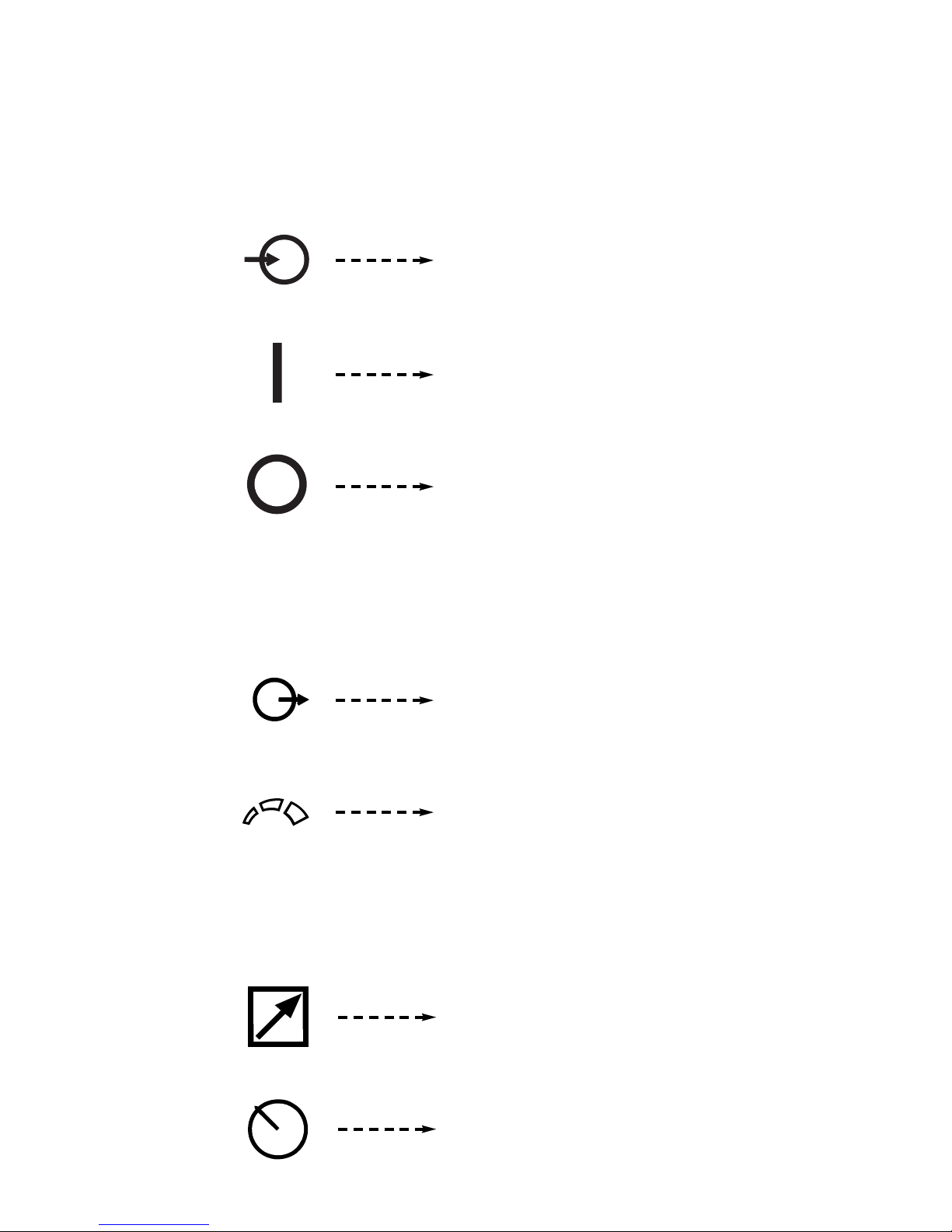
POWER ON-OFF SWITCH
Input (Power)
On
Off
OUTPUT CONTROL DIAL
V
OUTPUT CONTROL “LOCAL-REMOTE” SWITCH
Output Voltage (Control)
Increase/Decrease of Output (Voltage)
Remote Output Voltage Control
Local Output Voltage Control
– 8 –

CIRCUIT BREAKER
THERMAL PROTECTION LIGHT
Circuit Breaker
High Temperature
VOLTMETER SWITCH
Voltmeter
Positive Electrode
Negative Electrode
– 9 –
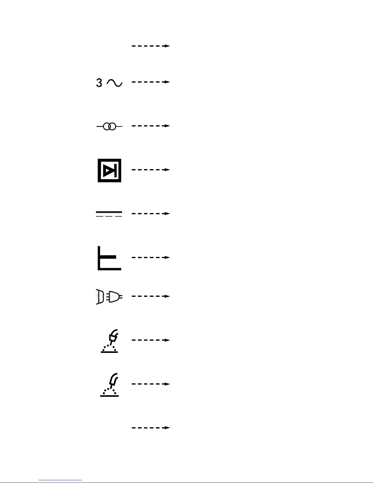
RATING PLATE
NEMA EW 1
Designates welder complies with National Electrical Manufacturers
ssociation requirements EW 1.
A
Three Phase Power
Transformer
Rectifier
Rectified DC Output
IP21
Constant Voltage Characteristic
Line Connection
Shielded Metal Arc Welding
Flux Cored Arc Welding
Degree of protection provided by the enclosure
– 10 –
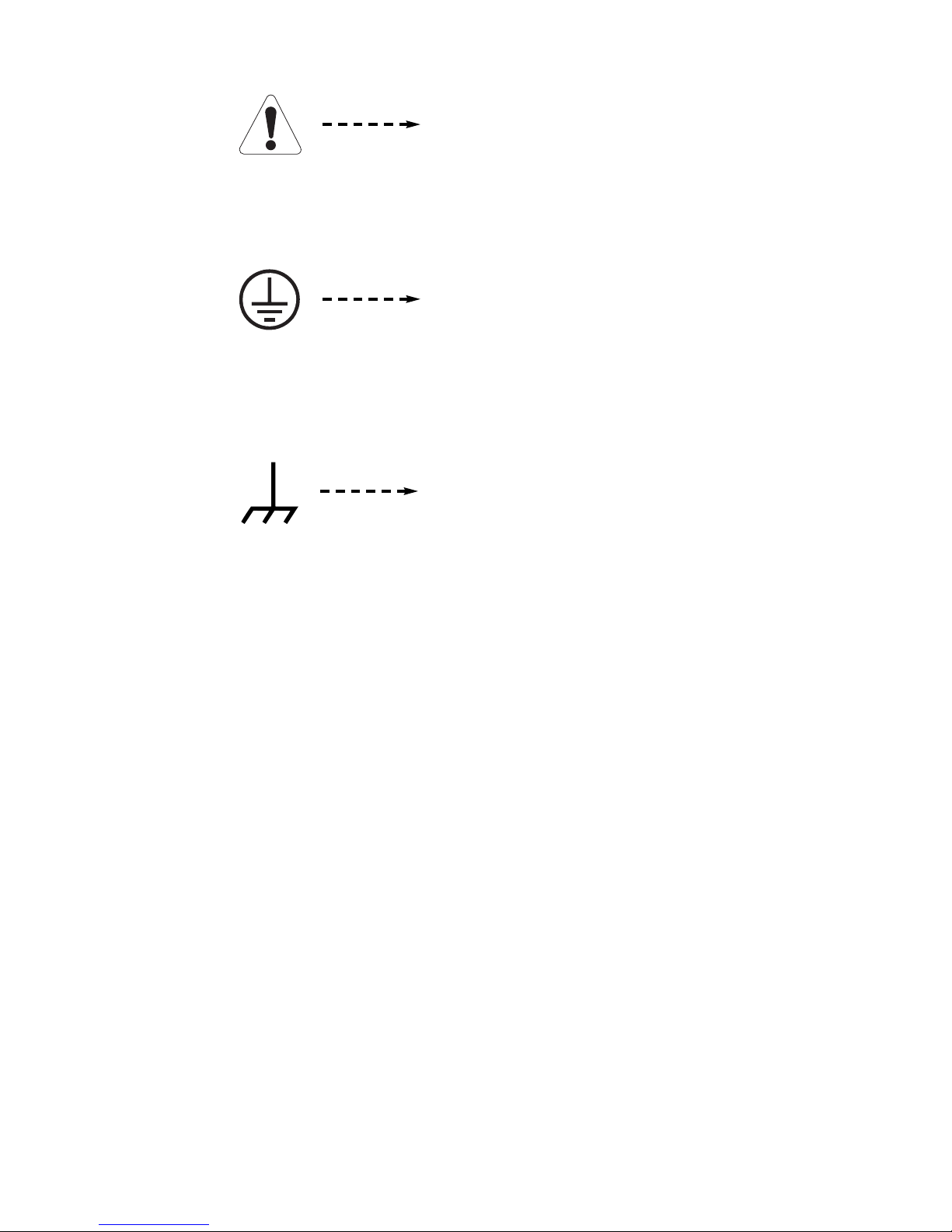
WARNING IDENTIFICATION
EARTH GROUND CONNECTION
CHASSIS GROUND CONNECTION
Warning Identification
Signifying the Earth (Ground) Connection
Signifying the Chassis (Ground) Connection
– 11 –

GENERAL MACHINE DESCRIPTION
MACHINE OUTPUT CONTROL SWITCH “LOCAL”
R “REMOTE”
O
The CV-400 is an SCR controlled three phase DC
power source. It is designed with a single range
potentiometer control.
RECOMMENDED PROCESSES
& EQUIPMENT
The CV-400 is supplied as a constant voltage power
source o n l y . It is designed for al l Innershield
Outershield®and all solid wire and gas procedures
within the capacity of the machine. The output characteristics have been optimized for these CV processes without use of a variable arc control.
The CV-400 is designed to be used with the LN-7,
LN-7 GMA, LN-8, LN-9, LN-9 GMA, LN-22, LN-23P*,
LN-25, or LN-742 semiautomatic wire feeders, the NA-3,
NA-5 and NA-5R automatics within the capacity of the
machine. The CV-400 Diode option is required to utilize the cold start and cold electrode sensing features
of the NA-3, NA-5 and NA-5R.
* For “Cold” gun use K350 Adapter Kit.
The machine output voltage can be controlled by
either the “OUTPUT CONTROL” on the machine control panel, the output control on the wire feed unit, or
an optional “remote control” that is available. This
witch selects the mode of control, either “LOCAL” or
s
“REMOTE”.
POLARITY SELECTION
®
,
Polarity selection is made by appropriately connecting
the electrode and work welding cables to either the
“
+” stud or to the “-” stud. Select “VOLTMETER”
switch for “+” or “-” electrode, for the remote (#21)
work sensing lead.
VOLTMETER SWITCH “+” ELECTRODE OR “-”
ELECTRODE
This switch selects electrode polarity for the remote
(#21) work sensing lead of automatic or semiautomatic equipment.
115 VOLT POWER SWITCH
DESIGN SUMMARY
Operational Features & Controls
ARC CHARACTERISTICS
Through the unique combination of the transformer,
three phase rectifier, capacitor bank, and output
choke design, in conjunction with the solid state control system, an outstanding constant voltage welding
performance is achieved with a fixed pinch setting
optimized for the most popular arc characteristics.
OUTPUT VOLTAGE CONTROL
The OUTPUT voltage control, a small 2 watt potentiometer, is calibrated from 1 to 10.
The power input contactor operates from an auxiliary
115 volt transformer that is energized through the
POWER toggle switch on the machine control panel.
“ I ” is on and “0” is off.
PILOT LIGHT
A white light on the machine control panel indicates
when the power source input contactor is closed. This
means the main power transformer and all auxiliary
and control transformers are energized.
THERMAL PROTECTION LIGHT
An amber light on the machine control panel indicates
when either of the two protective thermostats have
opened. Output power will be removed but input
power will still be applied to the machine.
INPUT CONTACTOR
The power source is equipped with an input contactor.
– 12 –

AUXILIARY POWER CONNECTIONS
SOLID STATE CONTROL SYSTEM
The power source is equipped to furnish nominally
115 volt AC and 42 volt AC auxiliary power for operating wire feeding equipment, etc. The auxiliary power
is available at the 14-pin MS-style connector receptacle on the control panel and/or at a terminal strip
ehind the hinged control panel on the front of the
b
power source. 115V AC is available at receptacle
pins A and J, and terminals 31 and 32. 42V AC is
available only at receptacle pins I and K. The 115V
AC and the 42V AC are isolated circuits and each is
protected by a 10 amp circuit breaker.
REMOTE CONTROL CONNECTIONS
Remote control connections are available both at a
14-pin connector receptacle located on the control
panel, and on terminal strips with screw connections
located behind the hinged control panel on the front of
the power source.
OUTPUT CONNECTIONS
The output terminals are recessed on the case front
and labeled “
INPUT CONNECTIONS
The three input lines are brought in through the rear
panel of the power source and attached to the input
contactor. Removal of the removable access panel
makes the contactor accessible for the input cable
connections.
INPUT LINE VOLTAGE COMPENSATION
The power source is equipped with input line voltage
compensation as standard. For a line voltage fluctuation of ±10% the output will remain essentially constant. This is accomplished through the feedback network in the control circuit.
SOLID STATE OUTPUT CONTROL
+” and “-”.
The Control PC Board is located behind the control
panel which hinges down for easy access to the
board. The Snubber PCBoard is mounted on the
back of the case front.
MACHINE COOLING
The fan pulls air in through the louvered front of the
machine over the internal parts and exhausts out the
louvered rear of the machine. The fan motor is fully
enclosed, has sealed ball bearings, requires no lubrication, and operates when the power switch is turned
on.
CASE FEATURES
The machine uses a 32” (813mm) long base. The low
profile case facilitates installation of the machine
under a workbench and stacking the machines three
high to conserve floor space.
The case front incorporates a recessed hinged control
panel where all the machine controls are mounted.
This recessed panel protects the controls and minimizes the possibilities of accidental contact. This control panel can be easily opened to permit access to
the enclosed section which contains the terminal
strips, PC board, etc.The output lead terminals are
also recessed to avoid any object or person accidentally coming in contact with an output terminal.
The individual case sides are removable for easy
access for internal service or inspection. These are
removable even though the machines are stacked
three high.
The case rear, top section, is equipped with a removable access panel. This provides easy access to the
input contactor, easy connection and reconnection of
input leads, and easy access for service or inspection.
Although the machine is designed for use in rain-sheltered
environments, the transformer and choke assembly
are dipped in a special corrosion resistant epoxy
paint.
The output of the welder is electronically controlled by
SCR’s instead of mechanical contactors, providing
extra long life for highly repetitive welding applications.
A permanent lifting hook is located at the top of the
machine and is positioned so that it acts as nearly as
possible through the center of gravity. This lift hook is
so positioned that it fits without interference under the
base of the second machine when stacking.
– 13 –

PARALLELING
There are no provisions on the CV-400 to permit paralleling.
DIODE OPTION (Factory installed only)
The CV-400 Diode option is required to utilize the cold
start and cold electrode sensing features of the NA-3,
NA-5 or NA-5R. When this option is not used with an
NA-3, NA-5 or NA-5R, see the CV-400 / NA-3,
CV-400 / NA-5 or CV-400 / NA-5R connection dia
for instructions on how to disable this circuit. If the circuit is not disabled, the wire cannot be inched down.
METER OPTION
Factory installed Ammeter and Voltmeter
gram
Machine & Circuit Protection
(Thermal Protection Light)
The power source is thermostatically protected with
proximity thermostats against overload or insufficient
cooling. One thermostat is located on the nose of the
center bottom primary coil and a second thermostat is
attached to the lead connecting the secondaries.
Both thermostats are connected in a series with the 24 circuit. If the machine is overloaded, the primary
thermostat will open, the output will be zero, and the
thermal protection light will be on; the fan will continue
to run. The secondary thermostat will open either with
an excessive overload or insufficient cooling. The output will be zero and the protection light will be on; the
fan will continue to run. When the thermostats reset
the protection light will be off.
The power source is also protected against overloads
on the SCR bridge assembly through an electronic
protection circuit. This circuit senses an overload on
the power source and limits the output to 550 amps by
phasing back the SCR’s.
Protection is provided to protect the circuitry from
accidental grounds. If the customer accidentally
“grounds” 75, 76, or 77 to the positive output lead, the
output will be reduced to a low value, thus preventing
any damage to the machine. If the ground occurs
between 75, 76, 77 and the negative output lead, one
of the PC board “self-restoring” fuses will blow, preventing any machine damage. After the ground is
cleared, the fuses automatically reset within a few
seconds.
– 14 –

TECHNICAL SPECIFICATIONS
Model
Type
Frequency
Output Rating
Amperes
Volts NEMA EW1
IEC 974-1
Duty Cycle
Output Range (Min.)
(Max.)
Max. O.C.V.
Input Ratings
Standard Voltages
Single Voltages (Available)
Rated Current
Input kVA
Power Factor
Efficiency
Idle Current
Idle Power
CV-400
K1346
60Hz
DC
500 450 400
40 38 36
-- -- - 50% 60% 100%
60A 12V
500A 42V
46
230/460
230/460/575
Yes
77A @ 400A 34V (230V)
30.7 @ 400A 34V
.65 @ 400A 34V
71% @ 400A 34V
5.2A (230V)
.9 KW
Optional Features
Remote Control Adapter Cable
115V Starter Circuit
Suitable Undercarriages
Remote output Control
Other Features
Net Weight
Dimension Print
Wiring Diagram
Standards Compliance
Operating Temperature
Yes
Standard
Yes
Yes
Stackable Case
383 Lbs (174 kg)
M12244-7
L9269
L9270 (230/460/575 Only)
NEMA EW1
UL/CSA
IP21
-40°C to +40°C
– 15 –

INSTALLATION
Safety Precautions
WARNING
ELECTRIC SHOCK can kill.
• Do not touch electrically live parts or
electrode with skin or wet clothing.
• In s ul a te you r s el f fr o m wo r k an d
ground.
• Always wear dry insulating gloves.
------------------------------------------------------------------------
FUMES AND GASES can be dangerous.
• Keep your head out of fumes.
• Use ventilation or exhaust to remove
fumes from breathing zone.
------------------------------------------------------------------------
WELDING SPARKS can cause fire or
explosion.
• Keep flammable material away.
• Do not weld on closed containers.
APPLICATION LIMITATIONS
here are no provisions on the CV-400 for paralleling,
T
and outdoor operations without rain sheltering is not
recommended.
LIMIT ON STACKING
WARNING
FALLING EQUIPMENT can cause
injury.
• Do not lift this machine using lift bale if
it is equipped with a heavy accessory
such as trailer or gas cylinder.
• Lift only with equipment of adequate lifting capacity.
• Be sure machine is stable when lifting.
• Do not stack more than three high.
• Do n ot stack the CV-400 on top of an y ot her
machine.
---------------------------------------------------------------------
The units may be stacked three high by observing the
following safety precautions.
------------------------------------------------------------------------
ARC RAYS can burn eyes and skin.
• Wear eye, ear and body
protection.
1. Make sure the first or bottom unit is setting on a
level, well supported surface.
2. The units must be stacked with their fronts flush,
making sure the two holes in the base rails of the
unit being stacked on top are over the two holes
------------------------------------------------------------
See additional warning information at
front of this operator’s manual.
-----------------------------------------------------------
CORRECT OPERATIONAL USE
The machine should be located in a clean, dry place
where there is free circulation of clean air such that air
movement in through the front and out through the
back will not be restricted. Dirt and dust that can be
drawn into the machine should be kept to a minimum.
Failure to observe these precautions can result in
excessive operating temperatures and nuisance shutdown of the machine.
located on the top front corners of the unit it is
being stacked on. Fasten the units together with
5/16 bolts, nuts and lockwashers through these
holes.
3. Remove fastening bolts before lifting unit off stacks.
Input Power Connections
By removing the rear access panel the three phase
input power is connected to the three line terminals on
the input contactor, and the earth grounding lead to
the grounding terminal on the input box floor marked
with the symbol. Install the reconnect panel
links for the proper input voltage per the diagram
inside the access panel cover.
See Installation Data below:
INSTALLATION DATA
Input Rating Recommended input wire and fuse sizes for maximum rated output.
In addition, follow latest National Electrical Code and Local Code.
Input Wire Size
Amperes** (Type 75°C Copper Wire Size
on Conductors in (Copper Conductors)
Voltage Hertz Nameplate Conduit)AWG AWG FUSE SIZE
230 60 77 3 (27mm2) 8 (10mm2) 100 Discont KTN-R-100
460 39 8 (8.4mm
575 31 10 (5.3mm2) 10 (5.3mm2) 40 RES-40 KTN-R-50
*
Ambient temperature of 40°C (104°F).
**
At rated output of 400A, 100% duty cycle.
***
Use only Bussmann Super-Lag or Limitron fuses specified. Other fuses may not protect the welder and
may cause overheating and possible fire damage.
*
Minimum Grounding
FUSE SIZE AND
CATALOG NUMBER***
BUSSMANN LIMITRON
SUPER-LAG
2
) 10 (5.3mm2) 50 RES-50 KTN-R-50
jumper
pasted
– 16 –

CAUTION
S
T RA IG HT P LU G (1 4 PI N)
T O P OW ER S OU RC E
C AB LE R EC E PTA C LE ( 6 S OC KE T)
C AB LE R E C EP TA CL E (1 4 SO CK ET )
TO : K8 57 RE MO TE C O NT RO L
T O : L N- 7 WI RE F E E DE RS
Failure to follow these instructions can cause immediate failure of components within the machine.
When powering welder from a generator be sure
o turn off the welder first, before generator is
t
shut down
in order to prevent damage to welder.
REMOTE CONTROL ADAPTER CABLE (K864)
Output Cable Connections
The output leads are connected to the output terminals marked “+” and “-”.
They are located at the lower
right and lower left corners of the front panel. The
CV-400 provides 1/2” studs for weld cable connection.
Output Cables
CABLE SIZES FOR COMBINED LENGTH OF
ELECTRODE AND WORK CABLE
MACHINE LOAD
CABLE LENGTHS
UP TO 50 ft
(15m)
50 to 100 ft
(15-30 m)
100-150 ft
(30-46 m)
150-200 ft
(46-61 m)
200-250 ft
(67-76 m)
400A
(100% DUTY
CYCLE)
3/0
85 mm
2
3/0
85 mm
2
3/0
85 mm
2
3/0
85 mm
2
4/0
107 mm
2
500A
(50% DUTY
CYCLE)
2/0
67 mm
2
2/0
67 mm
2
3/0
85 mm
2
3/0
85 mm
2
4/0
107 mm
2
Installation of Field Installed Options
A “ V ” cable 12 ” (.30m) l o n g to co n n ect a K857
Remote Control (6 pin connector) with a wire-feeder
(14-pin connector) and the machine (14-pin connector). If a remote control or amptrol is used alone the
wire-feeder connection is then not used.
WARNING
ELECTRIC SHOCK can kill.
• Turn the power switch of the
wel ding p ower so urc e “ OFF”
before installing plugs on cables or
when connecting or disconnecting plugs to
welding power source.
------------------------------------------------------------
CAPACITOR DISCHARGE CIRCUIT (K828-1)
Circu i t that m ou nt s insid e the C V- 4 00 .
Recommended when:
1) CV-400 is used in conjunction with any LN-23P or
older LN-8 or LN-9 semiautomatic wire-feeder.
Eliminates possible arc flash re-start of weld when
trigger interlock is used. Not required with current
LN-8 (above Code 8700), or LN-9’s with serial
numbers a b o v e 115187 (manufactured a f t e r
12/83), or any LN-9 having an L6043-1 Power PC
Board.
REMOTE OUTPUT CONTROL
(K857 WITH K864 ADAPTER OR K775 )
The K857 has a 6-pin MS-style connector. The K857
requires a K864 adapter cable which connects to the
14-pin connector on the machine.
The K775 consists of a control box with 28 ft (8.5m) of
four conductor cable. This connects to terminals 75, 76,
and 77 on the terminal strip and the case grounding
screw so marked with the symbol on the machine.
These terminals are located behind the control panel on
the front of the power source. This control will give the
same control as the output control on the
machine.
2) CV-400 is used with an LN-22 equipped with an
older K279 Contactor-Voltage Control Option.
Eliminates electrode overrun when gun trigger is
released. Not required when later K279 (above
Code 8800) is used.
3) CV-400 is used with any semiautomatic wire-feed-
er and possible small spark, if electrode touches
work just after gun trigger is released, is objectionable.
Install per M17060 instructions included with the
Kit.
– 17 –

UNDERCARRIAGES (K817P, K841)
For easy moving of the machine, optional undercarriages are available with polyolefin wheels (K817P) or
a platform undercarriage (K841) with mountings for
two gas cylinders at rear of welder.
nstall per instructions provided with undercarriage.
I
Installation of Equipment Required for
Recommended Processes
WIRE FEEDER CONTROL CABLE CONNECTIONS
For control cable with 14-pin connector:
onnect control cable to 14-pin connector on the front
C
panel of the machine. See the appropriate connection
diagram for the exact instructions for the wire feeder
being used. Refer to “115VAC and 42VAC Auxiliary
Power and Control Connections” section for connector
pin functions.
A cover (Lincoln Electric Part Number S17062-3) is
available for the unused 14-pin connector to protect it
against dirt and moisture.
For control cable with terminal strip connectors:
The control cable from the wire feeding equipment is
connected to the terminal strips behind the control
panel. A strain relief box connector is provided for
access into the terminal strip section. A chassis
ground screw is also provided below the terminal strip
marked with the symbol for connecting the automatic equipment grounding wire. See the appropriate
connection diagram for the exact instructions for the
wire feeder being used. Refer to “115VAC and 42VAC
Auxiliary Power and Control Connections” section for
access to terminal strips.
CONNECTION OF CV-400 TO LN-22 OR LN-25
a) Turn off all power.
b) Connect a jumper from “2 to 4” on terminal strip
TS2 or jumper pins “C to D” in 14-pin connector
plug ( a K484 14-pin jumper plug is available).
c) Connect the electrode cable to the output terminal
of polarity required by electrode. Connect the work
lead to the other terminal.
d) Place the OUTPUT CONTROL Switch at “LOCAL”
position unless a Remote Control is connected to
the CV-400.
NOTE: The output terminals are energized at all
times.
– 18 –
OPERATING INSTRUCTIONS
Safety Precautions
WARNING
ELECTRIC SHOCK can kill.
Have an electrician install and service
•
this equipment.
• Turn the input power off at the fuse
box before working on equipment.
• Do not touch electrically hot parts.
• This next section applies to CV-400’s without
Capacitor Discharge Option:
---------------------------------------------------------------------
When using a CV-400 power source with wire feeders,
there will be a small spark if the electrode contacts the
work or ground within several seconds after releasing
the trigger.
When used with some wire feeders with the electrical
trigger interlock in the ON position, the arc can restart
if the electrode touches the work or ground during
these several seconds.
the
POWER SOURCE OPERATION
uty Cycle and Time Period
D
The CV-400 is rated at the following duty cycles:
Duty Cycle* Amps Volts
100% 400 36
60% 450 38
50% 500 40
* Based upon a 10 minute time period. (i.e., for 60%
duty cycle, it is 6 minutes on and 4 minutes off).
Overloading the power source may result in opening
of an internal protective thermostat as indicated by the
amber thermal protection light turning on.
STARTING THE MACHINE
The POWER toggle switch at the extreme right side of
the control panel in the “ I “ position energizes and
closes the three phase input contactor from a 115 volt
auxiliary transformer. This in turn energizes the main
power transformer.
The machine is de-energized when the P OWER
switch is in the “0” position.
The white light next to the POWER switch indicates
when the input contactor is energized.
OUTPUT VOLTAGE CONTROL DIAL
The Output control dial at the right of the control panel
is a continuous control of the machine output voltage.
The control may be rotated between minimum and
maximum to adjust the machine output, even while
welding.
The machine is equipped with line voltage compensation as a standard feature. This will hold the output
constant except at maximum output of the machine,
through a fluctuation of ±10% input line voltage.
– 19 –
 Loading...