

Page 1
Operator’s Manual
HELIX ® M45 WELD HEAD
For use with machines having Code Numbers:
12885
ORIGINAL INSTRUCTIONS
Register your machine:
www.lincolnelectric.com/register
Authorized Service and Distributor Locator:
www.lincolnelectric.com/locator
Save for future reference
Date Purchased
Code: (ex: 12735)
Serial: (ex: U1060512345)
IM6129 | Issue D ate 02/19
© Lincoln Global, Inc. All Rights Reserved.
Need Help? Call 1.888.935.3877
to talk to a Service Representative
Hours of Operation:
8:00 AM to 6:00 PM (ET) Mon. thru Fri.
After hours?
Use “Ask the Experts” at lincolnelectric.com
A Lincoln Service Representative will contact you
no later than the following business day.
For Service outside the USA:
Email: globalservice@lincolnelectric.com
c/o Balmes, 89 - 80 2
08008 Barcelona
SPAIN
a
Page 2
HELIX® M45 WELD HEAD
THANK YOU FOR SELECTING
A QUALITY PRODUCT BY
LINCOLN ELEC TRIC.
PLEASE EXAMINE CARTON AND EQUIPMENT FOR
DAMAGE IMMEDIATELY
When this equipment is shipped, title passes to the purchaser
upon receipt by the carrier. Consequently, claims for material
damaged in shipment must be made by the purchaser against the
transportation company at the time the shipment is received.
SAFETY DEPENDS ON YOU
Lincoln arc welding and cutting equipment is designed and built
with safety in mind. However, your overall safety can be increased
by proper installation ... and thoughtful operation on your part.
DO NOT INSTALL, OPERATE OR REPAIR THIS EQUIPMENT
WITHOUT READING THIS MANUAL AND THE SAFETY
PRECAUTIONS CONTAINED THROUGHOUT. And, most importantly,
think before you act and be careful.
WARNING
This statement appears where the information must be followed
exactly to avoid serious personal injury or loss of life.
CAUTION
This statement appears where the information must be followed
to avoid minor personal injury or damage to this equipment.
SAFETY
KEEP YOUR HEAD OUT OF THE FUMES.
DON’T get too close to the arc.
Use corrective lenses if necessary
to stay a reasonable distance
away from the arc.
READ and obey the Safety Data
Sheet (SDS) and the warning label
that appears on all containers of
welding materials.
USE ENOUGH VENTILATION or
exhaust at the arc, or both, to
keep the fumes and gases from
your breathing zone and the general area.
IN A LARGE ROOM OR OUTDOORS, natural ventilation may be
adequate if you keep your head out of the fumes (See below).
USE NATURAL DRAFTS or fans to keep the fumes away
from your face.
If you de velop unusual symptoms, see your supervisor.
Perhaps the welding atmosphere and ventilation system
should be checked.
WEAR CORRECT EYE, EAR &
BODY PROTECTION
PROTECT your eyes and face with welding helmet
properly fitted and with proper grade of filter plate
(See ANSI Z49.1).
PROTECT your body from welding spatter and arc
flash with protective clothing including woolen
clothing, flame-proof apron and gloves, leather
leggings, and high boots.
PROTECT others from splatter, flash, and glare
with protective screens or barriers.
IN SOME AREAS, protection from noise may be appropriate.
BE SURE protective equipment is in good condition.
Also, wear safety glasses in work area
AT ALL TIMES.
SPECIAL SITUATIONS
DO NOT WELD OR CUT containers or materials which previously
had been in contact with hazardous substances unless they are
properly cleaned. This is extremely dangerous.
DO NOT WELD OR CUT painted or plated parts unless special
precautions with ventilation have been taken. They can release
highly toxic fumes or gases.
Additional precautionary measures
PROTECT compressed gas cylinders from excessive heat,
mechanical shocks, and arcs; fasten cylinders so they cannot fall.
BE SURE cylinders are never grounded or part of an
electrical circuit.
REMOVE all potential fire hazards from welding area.
ALWAYS HAVE FIRE FIGHTING EQUIPMENT READY FOR
IMMEDIATE USE AND KNOW HOW TO USE IT.
2
Page 3
HELIX® M45 WELD HEAD
SAFETY
SAFETY
SECTION A:
WARNINGS
CALIFORNIA PROPOSITION 65 WARNINGS
WARNING: Breathing diesel engine exhaust
exposes you to chemicals known to the State
of California to cause cancer and birth defects,
or other reproductive harm.
• Always start and operate the engine in a
well-ventilated area.
• If in an exposed area, vent the exhaust to the outside.
• Do not modify or tamper with the exhaust system.
• Do not idle the engine except as necessary.
For more information go to
www.P65 warnings.ca.gov/diesel
WARNING: This product, when used for welding or
cutting, produces fumes or gases which contain
chemicals known to the State of California to cause
birth defects and, in some cases, cancer. (California
Health & Safety Code § 25249.5 et seq.
)
with hot engine parts and igniting. Do not spill fuel when filling
tank. If fuel is spilled, wipe it up and do not start engine until
fumes have been eliminated.
1.d. Keep all equipment safety guards, covers
and devices in position and in good repair.
Keep hands, hair, clothing and tools away
from V-belts, gears, fans and all other
moving parts when starting, operating or
repairing equipment.
1.e. In some cases it may be necessary to remove safety guards to
perform required maintenance. Remove guards only when
necessary and replace them when the maintenance requiring
their removal is complete. Always use the greatest care when
working near moving parts.
1.f. Do not put your hands near the engine fan. Do not attempt to
override the governor or idler by pushing on the throttle control
rods while the engine is running.
1.g. To prevent accidentally starting gasoline engines while turning
the engine or welding generator during maintenance work,
disconnect the spark plug wires, distributor cap or magneto wire
as appropriate.
1.h. To avoid scalding, do not remove the radiator
pressure cap when the engine is
hot.
WARNING: Cancer and Reproductive Harm
www.P65warnings.ca.gov
ARC WELDING CAN BE HAZARDOUS. PROTECT
YOURSELF AND OTHERS FROM POSSIBLE SERIOUS
INJURY OR DEATH. KEEP CHILDREN AWAY.
PACEMAKER WEARERS SHOULD CONSULT WITH
THEIR DOCTOR BEFORE OPERATING.
Read and understand the following safety highlights. For
additional safety information, it is strongly recommended
that you purchase a copy of “Safety in Welding & Cutting ANSI Standard Z49.1” from the American Welding Society,
P.O. Box 351040, Miami, Florida 33135 or CSA Standard
W117.2-1974. A Free copy of “Arc Welding Safety” booklet
E205 is available from the Lincoln Electric Company,
22801 St. Clair Avenue, Cleveland, Ohio 44117-1199.
BE SURE THAT ALL INSTALLATION, OPERATION,
MAINTENANCE AND REPAIR PROCEDURES ARE
PERFORMED ONLY BY QUALIFIED INDIVIDUALS.
FOR ENGINE POWERED
EQUIPMENT.
1.a. Turn the engine off before troubleshooting
and maintenance work unless the
maintenance work requires it to be running.
1.b. Operate engines in open, well-ventilated areas or vent the engine
exhaust fumes outdoors.
1.c. Do not add the fuel near an open flame welding
arc or when the engine is running. Stop the
engine and allow it to cool before refueling to
prevent spilled fuel from vaporizing on contact
ELECTRIC AND
MAGNETIC FIELDS MAY
BE DANGEROUS
2.a. Electric current flowing through any conductor
causes localized Electric and Magnetic Fields (EMF).
Welding current creates EMF fields around welding cables
and welding machines
2.b. EMF fields may interfere with some pacemakers, and
welders having a pacemaker should consult their physician
before welding.
2.c. Exposure to EMF fields in welding may have other health effects
which are now not known.
2.d. All welders should use the following procedures in order to
minimize exposure to EMF fields from the welding circuit:
2.d.1. Route the electrode and work cables together - Secure
them with tape when possible.
2.d.2. Never coil the electrode lead around your body.
2.d.3. Do not place your body between the electrode and work
cables. If the electrode cable is on your right side, the
work cable should also be on your right side.
2.d.4. Connect the work cable to the workpiece as close as possible to the area being welded.
2.d.5. Do not work next to welding power source.
3
Page 4
HELIX® M45 WELD HEAD
SAFETY
SAFETY
ELECTRIC SHOCK
CAN KILL.
3.a. The electrode and work (or ground) circuits are
electrically “hot” when the welder is on. Do
not touch these “hot” parts with your bare skin or wet clothing.
Wear dry, hole-free gloves to insulate hands.
3.b. Insulate yourself from work and ground using dry insulation.
Make certain the insulation is large enough to cover your full area
of physical contact with work and ground.
In addition to the normal safety precautions, if
welding must be performed under electrically
hazardous conditions (in damp locations or while
wearing wet clothing; on metal structures such as
floors, gratings or scaffolds; when in cramped
positions such as sitting, kneeling or lying, if there
is a high risk of unavoidable or accidental contact
with the workpiece or ground) use the following
equipment:
• Semiautomatic DC Constant Voltage (Wire) Welder.
• DC Manual (Stick) Welder.
• AC Welder with Reduced Voltage Control.
3.c. In semiautomatic or automatic wire welding, the electrode,
electrode reel, welding head, nozzle or semiautomatic welding
gun are also electrically “hot”.
3.d. Always be sure the work cable makes a good electrical
connection with the metal being welded. The connection should
be as close as possible to the area being welded.
3.e. Ground the work or metal to be welded to a good electrical (earth)
ground.
3.f. Maintain the electrode holder, work clamp, welding cable and
welding machine in good, safe operating condition. Replace
damaged insulation.
3.g. Never dip the electrode in water for cooling.
3.h. Never simultaneously touch electrically “hot” parts of electrode
holders connected to two welders because voltage
two can be the total of the open circuit voltage of both
welders.
3.i. When working above floor level, use a safety belt to protect
yourself from a fall should you get a shock.
3.j. Also see It ems 6.c. and 8.
between the
ARC RAYS CAN BURN.
4.a. Use a shield with the proper filter and cover plates to protect your
eyes from sparks and the rays of the arc when welding or
observing open arc welding. Headshield and filter lens should
conform to ANSI Z87. I standards.
4.b. Use suitable clothing made from durable flame-resistant material
to protect your skin and that of your helpers from the arc rays.
4.c. Protect other nearby personnel with suitable, non-flammable
screening and/or warn them not to watch the arc nor expose
themselves to the arc rays or to hot spatter or metal.
FUMES AND GASES
CAN BE DANGEROUS.
5.a. Welding may produce fumes and gases
hazardous to health. Avoid breathing these
fumes and gases. When welding, keep your head out of the fume.
Use enough ventilation and/or exhaust at the arc to keep fumes
and gases away from the breathing zone. When welding
hardfacing (see instructions on container or SDS)
or on lead or cadmium plated steel and other
metals or coatings which produce highly toxic
fumes, keep exposure as low as possible and
within applicable OSHA PEL and ACGIH TLV limits
using local exhaust or mechanical ventilation
unless exposure assessments indicate otherwise.
In confined spaces or in some circumstances,
outdoors, a respirator may also be required.
Additional precautions are also required when
welding
on galvanized steel.
5. b. The operation of welding fume control equipment is affected by
various factors including proper use and positioning of the
equipment, maintenance of the equipment and the specific
welding procedure and application involved. Worker exposure
level should be checked upon installation and periodically
thereafter to be certain it is within applicable OSHA PEL and
ACGIH TLV limits.
5.c. Do not weld in locations near chlorinated hydrocarbon vapors
coming from degreasing, cleaning or spraying operations. The
heat and rays of the arc can react with solvent vapors to form
phosgene, a highly toxic gas, and other irritating products.
5.d. Shielding gases used for arc welding can displace air and
injury or death. Always use enough ventilation, especially in
confined areas, to insure breathing air is safe.
5.e. Read and understand the manufacturer’s instructions for this
equipment and the consumables to be used, including the
Safety Data Sheet (SDS) and follow your employer’s safety
practices. SDS forms are available from your welding
distributor or from the manufacturer.
5.f. Also see item 1.b.
cause
4
Page 5
HELIX® M45 WELD HEAD
SAFETY
SAFETY
WELDING AND CUTTING
SPARKS CAN CAUSE
FIRE OR EXPLOSION.
6.a. Remove fire hazards from the welding area. If
this is not possible, cover them to prevent the welding sparks
from starting a fire. Remember that welding sparks and hot
materials from welding can easily go through small cracks and
openings to adjacent areas. Avoid welding near hydraulic lines.
Have a fire extinguisher readily available.
6.b. Where compressed gases are to be used at the job site, special
precautions should be used to prevent hazardous situations.
Refer to “Safety in Welding and Cutting” (ANSI Standard Z49.1)
and the operating information for the equipment being used.
6.c. When not welding, make certain no part of the electrode circuit is
touching the work or ground. Accidental contact can cause
overheating and create a fire hazard.
6.d. Do not heat, cut or weld tanks, drums or containers until the
proper steps have been taken to insure that such procedures
will not cause flammable or toxic vapors from substances inside.
They can cause an explosion even though they have been
“cleaned”. For information, purchase “Recommended Safe
Practices for the Preparation for Welding and Cutting of
Containers and Piping That Have Held Hazardous Substances”,
AWS F4.1 from the American Welding Society
(see address above).
6.e. Vent hollow castings or containers before heating, cutting or
welding. They may explode.
6.f. Sparks and spatter are thrown from the welding arc. Wear oil free
protective garments such as leather gloves, heavy shirt, cuffless
trousers, high shoes and a cap over your hair. Wear ear plugs
when welding out of position or in confined places. Always wear
safety glasses with side shields when in a welding area.
6.g. Connect the work cable to the work as close to the welding area
as practical. Work cables connected to the building framework or
other locations away from the welding area increase the
possibility of the welding current passing through lifting chains,
crane cables or other alternate circuits. This can create fire
hazards or overheat lifting chains or cables until they fail.
6.h. Also see item 1.c.
6.I. Read and follow NFPA 51B “Standard for Fire Prevention During
Welding, Cutting and Other Hot Work”, available from NFPA, 1
Batterymarch Park, PO box 9101, Quincy, MA 022690-9101.
6.j. Do not use a welding power source for pipe thawing.
CYLINDER MAY EXPLODE IF
DAMAGED.
7.a. Use only compressed gas cylinders containing
the correct shielding gas for the process used
and properly operating regulators designed for
the gas and pressure used. All hoses, fittings,
etc. should be suitable for the application and
maintained in good condition.
7.b. Always keep cylinders in an upright position securely chained to
an undercarriage or fixed support.
7.c. Cylinders should be located:
• Away from areas where they may be struck or subjected
to physical damage.
• A safe distance from arc welding or cutting operations
and any other source of heat, sparks, or flame.
7.d. Never allow the electrode, electrode holder or any other
electrically “hot” parts to touch a cylinder.
7.e. Keep your head and face away from the cylinder valve outlet
when opening the cylinder valve.
7.f. Valve protection caps should always be in place and hand tight
except when the cylinder is in use or connected for use.
7.g. Read and follow the instructions on compressed gas cylinders,
associated equipment, and CGA publication P-l, “Precautions for
Safe Handling of Compressed Gases in Cylinders,” available from
the Compressed Gas Association, 14501 George Carter Way
Chantilly, VA 20151.
FOR ELECTRICALLY
POWERED EQUIPMENT.
8.a. Turn off input power using the disconnect
switch at the fuse box before working on
the equipment.
8.b. Install equipment in accordance with the U.S. National Electrical
Code, all local codes and the manufacturer’s recommendations.
8.c. Ground the equipment in accordance with the U.S. National
Electrical Code and the manufacturer’s recommendations.
Refer to
http://www.lincolnelectric.com/safety
for additional safety information.
5
5
Page 6

HELIX® M45 WELD HEAD
SAFETY
ELECTROMAGNETIC
COMPATIBILITY (EMC)
CONFORMANCE
Products displaying the CE mark are in conformity with European Community
Council Directive of 3 May 1989 on the approximation of the laws of the
Member States relating to electromagnetic compatibility (2014/30/UE). It
was manufactured in conformity with a national standard that implements a
harmonized standard: EN 60974-10
Electromagnetic Compatibility (EMC) Product Standard for Arc Welding
Equipment. It is for use with other Lincoln Electric equipment. It is designed
for industrial and professional use.
INTRODUCTION
All electrical equipment generates small amounts of electromagnetic
emission. Electrical emission may be transmitted through power lines or
radiated through space, similar to a radio transmitter. When emissions are
received by other equipment, electrical interference may result. Electrical
emissions may affect many kinds of electrical equipment; other nearby
welding equipment, radio and TV reception, numerical controlled machines,
telephone systems, computers, etc. Be aware that interference may result
and extra precautions may be required when a welding power source is used
in a domestic establishment.
INSTALLATION AND USE
The user is responsible for installing and using the welding equipment
according to the manufacturer’s instructions. If electromagnetic disturbances
are detected then it shall be the responsibility of the user of the welding
equipment to resolve the situation with the technical assistance of the
manufacturer. In some cases this remedial action may be as simple as
earthing (grounding) the welding circuit, see Note. In other cases it could
involve construction of an electromagnetic screen enclosing the power source
and the work complete with associated input filters. In all cases electromagnetic disturbances must be reduced to the point where they are no longer
troublesome.
Note: The welding circuit may or may not be earthed for safety reasons according to national codes.
Changing the earthing arrangements should only be authorized by a person who is competent to
access whether the changes will increase the risk of injury, e.g., by allowing parallel welding current
return paths which may damage the earth circuits of other equipment.
ASSESSMENT OF AREA
Before installing welding equipment, the user shall make an assessment of
potential electromagnetic problems in the surrounding area. The following
shall be taken into account:
a. Other supply cables, control cables, signaling and telephone cables; above, below
and adjacent to the welding equipment;
b. radio and television transmitters and receivers;
c. computer and other control equipment;
d. safety critical equipment, e.g., guarding of industrial equipment;
e. the health of the people around, e.g., the use of pacemakers and hearing aids;
f. equipment used for calibration or measurement and
g. the immunity of other equipment in the environment. The user shall ensure that other
equipment being used in the environment is compatible. This may require additional
protection measures including:
h. the time of day that welding or other activities are to be carried out.
The size of the surrounding area to be considered will depend on the
structure of the building and other activities that are taking place. The
surrounding area may extend beyond the boundaries of the premises.
METHODS OF REDUCING EMISSIONS
Mains Supply
Welding equipment should be connected to the mains supply according
to the manufacturer’s recommendations. If interference occurs, it may be
necessary to take additional precautions such as filtering of the mains supply.
Consideration should be given to shielding the supply cable of permanently
installed welding equipment, in metallic conduit or equivalent. Shielding
should be electrically continuous throughout its length. The shielding should
be connected to the welding power source so that good electrical contact is
maintained between the conduit and the welding power source enclosure.
Maintenance of the Welding Equipment
The welding equipment should be routinely maintained according to the
manufacturer’s recommendations. All access and service doors and covers
should be closed and properly fastened when the welding equipment is in
operation. The welding equipment should not be modified in any way except
for those changes and adjustments covered in the manufacturers instructions.
In particular, the spark gaps of arc striking and stabilizing devices should be
adjusted and maintained according to the manufacturer’s recommendations.
Welding Cables
The welding cables should be kept as short as possible and should be
positioned close together, running at or close to floor level.
Equipotential Bonding
Bonding of all metallic components in the welding installation and adjacent
to it should be considered. However, metallic components bonded to the
work piece will increase the risk that the operator could receive a shock by
touching these metallic components and the electrode at the same time. The
operator should be insulated from all such bonded metallic components.
Earthing of the Workpiece
Where the workpiece is not bonded to earth for electrical safety, not
connected to earth because of its size and position, e.g., ships hull or
building steelwork, a connection bonding the workpiece to earth may reduce
emissions in some, but not all instances. Care should be taken to prevent the
earthing of the work piece increasing the risk of injury to users, or damage to
other electrical equipment. Where necessary, the connection of the workpiece
to earth should be made by a direct connection to the work piece, but in some
countries where direct connection is not permitted, the bonding should be
achieved by suitable capacitance, selected according to national regulations.
Screening and Shielding
Selective screening and shielding of other cables and equipment in the
surrounding area may alleviate problems of interference. Screening of the
entire welding installation may be considered for special applications.
1 Portions of the preceding text are contained in EN 60974-10: “Electromagnetic
Compatibility (EMC) product standard for arc welding equipment.”
6
Page 7

HELIX® M45 WELD HEAD
SAFETY
7
Page 8

HELIX® M45 WELD HEAD
TABLE OF CONTENTS
Safety .............................................................................................................................................................. 3
Disposal Guide .......................................................................................................................................... 7
Dimensions ................................................................................................................................................A-1
Technical Specications ........................................................................................................................... A-2
Safety Precautions ...................................................................................................................................A-3
Proper handling ..................................................................................................................................... A-3
Operation .............................................................................................................................................. A-3
HELIX M45 WELD HEAD ........................................................................................................................... A-4
Basic Information .................................................................................................................................. A-4
Basic Components ................................................................................................................................ A-4
Body Assembly ..................................................................................................................................... A-4
Main Body Assembly ............................................................................................................................ A-4
Torch Height Assembly ......................................................................................................................... A-4
Work Angle Adjustment .........................................................................................................................A-5
Track Engagement ................................................................................................................................ A-5
Handle Adjustment ................................................................................................................................ A-5
Operational Safety Precautions ...............................................................................................................B-1
Operation Information ........................................................................................................................... B-1
External inputs ..................................................................................................................................... B-1
Control ...................................................................................................................................................B-1
Welding Power ......................................................................................................................................B-1
Manual Adjustments ............................................................................................................................. B-1
Accessories .........................................................................................................................................B-1
Maintenance ........................................................................................................................................D-1
Maintenance Schedule ..........................................................................................................................D-1
Every Shift ............................................................................................................................................. D-1
Monthly .................................................................................................................................................D-1
Semi Annually ........................................................................................................................................D-1
Tools ...................................................................................................................................................... D-1
Belt Change Adjustment .......................................................................................................................D-2
Trouble Shooting ....................................................................................................................................... F-1
Wiring Diagram ..........................................................................................................................................G-1
Helix M45 Parts Manual ............................................................................................................................H-1
Page 9
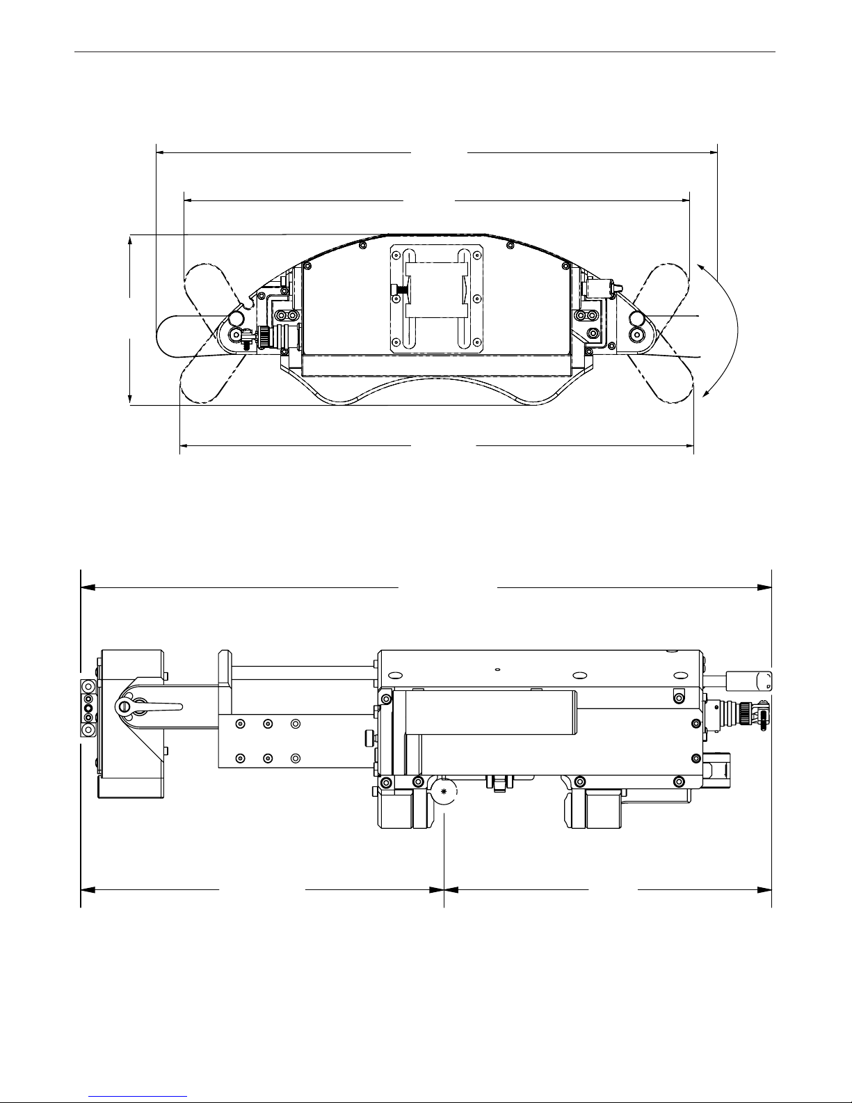
HELIX M45 Weld Head Dimensions
16.63 in
42.24 cm
14.96 in
38.99 cm
5.08 in
12.90 cm
INSTALLATIONHELIX® M45 WELD HEAD
15.22 in
38.65 cm
View Front
19.70 in±2.5 in
50.08 cm± 6.35 cm
10.35±2.5 in
26.28±6.35 cm
9.3 in
23.62 cm
View Side
A-1
Page 10

Technical Specications HELIX M45 Weld Head
HELIX M45 Weld head
Product Number
K52224-1
Input Power 24 VDC
Radial Clearance (on 8" Track Ring) 4.5" (114.3 mm)
Travel Speed 0.1 - 120 ipm
Max Oscillation Speed 150 ipm (381 cm/min)
Oscillation stroke 5" (49.78 mm)
Work Angle +45 degrees in / -45 degrees out
Pipe Sizes 8" OD to Flat Track
Weld Head Physical Dimensions
Depth (minus the torch): 19.70” (500.38 mm) Weight: 28 lbs (12.7 kg)
Environmental
Operating Temperature Range
32F to 140F (0C - 60C)
Ingress Protection - IP00
Storage Temperature Range
-22F to 140F (0C - 60C)
INSTALLATIONHELIX® M45 WELD HEAD
A-weighted emission sound pressure level: less than 70 db (A)
Explanation of Symbols
Electric Shock Warning Hot Surface Warning
A-2
Page 11

INSTALLATIONHELIX® M45 WELD HEAD
Safety Precautions
Read entire manual before installation or operation.
WARNING
ELECTRIC SHOCK CAN KILL
• Only qualied personnel
should perform this installation.
• Turn the input power OFF
at the disconnect switch
or fuse box before working on this equipment turn
off the input power to any
other equipment connected to the welding system
at the disconnect switch
or fuse box before working
on the equipment.
• Do not touch electrically
hot parts.
• Always connect the power
supply grounding lug to
a proper safety (Earth)
ground.
Operation
Read entire manual before operation.
Only operate the HELIX M45 weld head while it is
rmly attached to the track ring with the clutch
engaged. Always verify that the track is properly
attached to the work surface before operating.
Keep hands away from weld head while in operation.
Verify that the system cable assembly is free from
obstruction before operating. While welding, the weld
head will rotate around the pipe. Be certain that there
is plenty of play in weld cable. If the cable binds up
during welding, parts of the weld cable or the weld
head assembly may become damaged.
Never unplug or plug in control cables to the weld
head while the system is powered on.
Verify that the system is properly grounded before
beginning to weld.
Proper Handling
The HELIX M45 weld head is only meant to be picked
up and supported by the handles. Only attempt to
attach the weld head to the track ring while the clamp
mechanism and clutch are disengaged.
Do not hang persons or objects from the handles of
the weld head while operating.
Keep machine dry. Shelter from rain and snow. Do not
place on wet ground or in puddles.
Always place the weld head on a steady, at level surface when not in use or not clamped onto a track ring.
Always be sure to engage the clutch when the weld
head is left on the track.
Do not force the torch motion assembly in or out manually. Manually adjusting the torch in this manner can
cause undue wear and tear on the gear and motors.
After welding allow adequate time for the weld head
to cool before moving, making adjustments or putting
into storage.
A-3
Page 12
INSTALLATIONHELIX® M45 WELD HEAD
HELIX M45 Weld Head
Basic Information
The HELIX M45 weld head is the second weld head in
the APEX 3 world of digitally controlled, precision
welding. Designed with a low prole, this device also
oers a pivoting torch height assembly, providing
perpendicular height control to the puddle face.
The handles on the HELIX M45 weld head rotate,
allowing for optimized clearance. Designed to work with
the APEX® 3 Series Orbital Controllers, the HELIX M45
weld head uses cross-roller bearings for rigid clamping
and is able to change weld parameters based on its
orientation in space.
The HELIX M45 weld head has automatic height
control, oscillation capabilities, and multiple toolless
torch adjustment options. These give the operator
greater control of the weld puddle for complex welds
in limited space.
Basic Components
The three basic components of the weld head are:
• Body Assembly
• Torch Clamp
• Torch Height Assembly
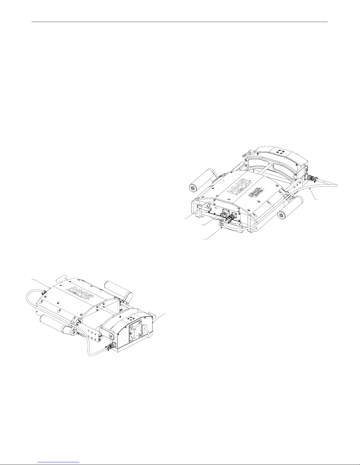
See FIGURE 1 - Weld Head Components –
for the dierent weld head parts. Each piece of
the machinery is discussed separately.
CLUTCH
HANDLE
Adjustments and controls located on the
body include:
• Clutch Handle
This handle is engaged with a pushing motion
and disengaged by a pulling motion. Pushing the
weld head back and forth along the track makes
the engagement of the clutch easier.
• Clamp Latch
Using a compression spring to add force to
the clamp, this latch engages or disengages
the clamp which secures the weld head onto
the track.This compensates for variance in
track width dimension and maintains weld
head position.
CONTROL
CABLE
INPUT
CLAMP
LATCH
FIGURE 2 - Rear Weld Head Components
ACCESSORY
CABLE
BODY
FIGURE 1 - Weld Head Components
Body Assembly
The body assembly is the main component for the
HELIX M45 weld head. It contains the gears, motors and belts that provide travel and oscillation for
the weld head – see FIGURES 1 and 2 - Weld Head
Components and Rear Weld Head Components.
TORCH
CLAMP
• Control Cable Input
A connecting point for the control cable which
delivers all signals to the weld head.
• Accessory Cable
TORCH
This cable connects the onboard wire feeder and
HEIGHT
the torch height assembly.
Torch Height Assembly
The torch height assembly holds the torch and provides vertical motion to the torch. It also allows for
toolless work angle adjustment.
A-4
Page 13

INSTALLATIONHELIX® M45 WELD HEAD
HANDLE ADJUSTMENT THUMB SCREW
Work Angle Adjustment
The HELIX M45 weld head allows for 45 degrees
of outward adjustment and 45 degrees of inward
adjustment. This angle is changed by using the work
angle adjustment handle shown in FIGURE 3 - Work
Angle Adjustment.
FIGURE 3 - Work Angle Adjustment
Track Engagement
Once the weld head is on the track, secure the clamp
latch – see FIGURE 5 - Secure to Track. Move the
tractor slowly on the track and push the clutch in to
engage drive gears.
FIGURE 5 - Secure to Track
Before placing on th HELIX M45 weld head on the
track, verify that the clamp latch is open and the clutch
is pulled out – see FIGURE 4 - Clamp Latch and
Clutch.
FIGURE 4 - Clamp Latch and Clutch
Handle Adjustment
The handles on the HELIX M45 weld head oer a
3-way toolless adjustment thumb screw, as shown in
FIGURE 6 - Handle Adjustment Screw.
FIGURE 6 - Handle Adjustment Screw
A-5
Page 14

HELIX® M45 WELD HEAD
OPERATION
Operational Safety Precautions
Read and understand this entire section before operating the machine.
WARNING
ELECTRIC SHOCK CAN KILL.
• Only qualied personnel should
perform the installation.
• Turn the input power OFF at the
disconnect switch or fuse box.
• Do not touch electrically live parts
or electrode with skin or wet clothing.
• Insulate yourself from work and
ground.
• Always dry insulating gloves.
• Read and follow “Electric Shock
Warnings” in the Safety section if
welding must be performed under
electrically hazardous conditions
such as welding in wet areas or on
or in the work pieces.
FUMES AND GASES
can be dangerous.
* Keep your head out of fumes.
* Use ventilation or exhaust to
remove fumes from breathing
zone.
Operation Information
The HELIX M45 weld head is designed for multiprocess welding and will work with any APEX® 3
Series Orbital Control System. For complete instal-
lation and operational instructions, see the specic
controller manual and the applicable process manual.
External Inputs
The external inputs for the HELIX M45 weld head are
control signals, and 24V DC.
Control
Control of the weld head and wire feeder is provided
by the APEX 3 Series controller. Through the use of a
handheld pendant, the operator is able to control and
monitor all aspects of the weld and change parameters
while welding.
Welding Power
Welding power is provided by a standard Lincoln
Electric Power Wave® or a Vantage® power source.
An ArcLink® connection is required.
Accessories
HELIX M45 Weld Head
Accessories and Consumables
WELDING SPARKS
can cause re and explosion
* Keep ammable material away.
* Do not weld on containers that
have held combustibles.
ARC RAYS
can burn.
* Wear eye, ear and body
protection.
Observe additional Safety Guidelines detailed in the
beginning of this manual.
Refer to control system manual for all operational
instructions.
Accessory
Weld Head Control Cable 25’ K52107-25
Weld Head Control Cable 50’ K52107-50
HELIX SF70C Onboard Wire Feeder 1 K52248-1
HELIX SF70C Onboard Wire Feeder 2 K52248-2
Low Prole Mechanized TIG Torch, 25’ K52249-25
Low Prole Mechanized MIG Torch, 25’ K52250-25
HELIX M45 Oscillation Arm Extension 6” K52251-06
HELIX M45 Oscillation Arm Extension 12” K52251-12
HELIX M45 Oscillation Arm Extension 18” K52251-18
HELIX M45 Oscillation Arm Extension 24” K52251-24
B-1
Part
Number
Page 15

HELIX® M45 WELD HEAD
Maintenance
The HELIX M45 weld head is designed for trouble-free
operation and normally requires minimal preventive
care and cleaning. This section provides instructions
for maintaining user-serviceable items. The suggested
repair procedure for all such items is to remove and
replace defective assemblies or parts.
When users and/or service personnel are not familiar
with electrical and electronic equipment, the product
should be returned to the factory or serviced by factory
authorized representatives.
Maintenance Schedule
The maintenance schedule is suggested as a guideline
for proper system maintenance. More stringent maintenance requirements may be required depending on
the work being performed and the requirements of the
customer for whom the work is performed. All maintenance schedules are based on a 40-hour work week.
Any excess play in parts or equipment should be
noted and reported to an authorized repair facility. Any
anomalous activity, such as motor hesitation, clicking
or other noises, or anything out of the ordinary should
be noted and reported to an authorized repair facility.
MAINTENANCE
• Check over all the weld head components for any
signs of damage or wear.
• Ensure track ring gears and weld head gears are
clean and clear of debris.
• Check for wear of drive rolls on wire feeder.
Semi Annually
• Based on a 40-hour work week it is recommended
that the belts be replaced every six months.
• Verify that all motors are working correctly without
strain. Listen to the motors to conrm that there is no
excess noise or grinding.
Tools
Required tools to operate and repair the HELIX M45
weld head:
• 2.5 mm hex key
• 3 mm hex key
• 4 mm hex key
• wire cutters
Further tools are required for in depth maintenance
which is only authorized at local repair facilities.
Every Shift
• Check lines, cables, and drive belts for loose connections and worn areas.
• Change out consumables as needed.
• Check torch height motion and travel for slop or
wearing parts.
NOTE: Do not force the oscillator in or out while
checking for worn parts.
• Inspect torch cable for wear or damage.
Monthly
• With the clutch and clamp latch engaged, grab the
weld head by the handles and gently move back and
forth to check for excess play in the weld head along
the track.
• Release the clutch latch and verify that the weld
head moves smoothly along the track without rubbing or binding.
• Examine all cable connections to verify that there are
no gas leaks, and that all cables are seated correctly
and that there is no visible wear and tear to any connector or associated cables.
D-1
Page 16

HELIX® M45 WELD HEAD
Belt Change Adjustment
There are two belts that will require changing with
frequent use: the Torch Height Belt see FIGURE 6
- Changing Torch Height Belt – and the oscillator
belt – see FIGURE 5 - Changing Oscillator Belt.
MAINTENANCE
DO NOT LOOSEN
Loosen Screw
Belt
FIGURE 6 - Changing Torch Height Belt
To change the Torch Height Belt:
1. Remove the bottom cover using a 2.5 mm
Hex Driver.
2. Loosen (DO NOT REMOVE) the two screws
shown in FIGURE 6 using a 3 mm Hex Driver and
slide the motor pulley towards the middle of the
Torch Height.
3. Remove the belt
4. Replace with a new belt (KP52252-1, see Parts
Manual on page H-9). Check that the belt is straight
and avoid over tightening to prevent machine malfunction. Push the motor pulley back into place and
tighten the two screws.
5. Replace the bottom cover.
Back Cover
Motor Pulley
FIGURE 7 - Changing Oscillator Belt
To change the Oscillator Belt:
1. Remove the back cover using a 2 mm
Hex Driver.
2. Loosen (DO NOT REMOVE) the screw shown in
FIGURE 7 using a 3 mm Hex Driver.
3. Push the motor pulley toward the center of the
weld head.
4. Replace with a new belt (KP52137-1, see Parts
Manual on page H-7). Check that the belt is straight
and avoid over tightening to prevent machine malfunction. Push the motor pulley back into place and
tighten the screw.
5. Replace the back cover.
D-2
Page 17

HELIX® M45 WELD HEAD
TROUBLE SHOOTING
Observe all Safety Guidelines detailed throughout this manual.
PROBLEMS
(SYMPTOMS)
Auto Height does not operate /
operates incorrectly.
Travel is inconsistent.
No oscillation /
inconsistent oscillation.
Wire does not feed properly.
POSSIBLE
CAUSE
1. Weld settings are incorrect.
2. Auto height is disabled.
3. Inconsistent wire feeding
4. Wire binding in contact tip.
1. Clutch is not fully engaged.
2. Loose communication cable.
3. Step travel is engaged.
1. Loose communication cable.
2. Oscillation settings are
incorrect
3. Oscillation arms binding on
wipers.
4. Worn oscillator belt.
1. Drive rolls are worn/damaged
2. Wire guides are restricting wire
passage.
3. Wire binding in contact tip.
4. Wire liner is kinked.
RECOMMENDED
COURSE OF ACTION
1. Check WFS/Amps
2. Check auto height is on.
3. Check wire.
4. Check contact tip.
1. Check clutch latch to ensure it
is engaged (locked).
2. Check all cable connections.
3. Check travel settings.
1. Check all cable connections.
2. Check oscillator settings on
jog screen.
3. Check wipers for free
movement.
4. Check oscillator belt.
1. Check drive rolls
2. Check wire feed for blockage.
3. Check contact tip.
4. Check for kinks or obstructions in the torch or wire liner.
1. Verify gas is turned on.
1. Gas supply is shut o.
Gas issues
Tractor drags on work surface 1. Track is improperly installed.
If all recommended possible areas of misadjustment have been checked and the problem persists,
Contact your local Lincoln Authorized Field Services Facility.
2. Gas tank is empty.
3. Gas hose is kinked.
2. Verify there is gas present in
the tank.
3. Check the gas line for kinks or
obstructions.
1. Check that the shoes are all
equally spaced around the
track.
If for any reason you do not understand the test procedures or are unable to perform the tests/repairs safely,
contact your Local Lincoln Authorized Field Service Facility for technical troubleshooting assistance before you proceed.
CAUTION
F-1
Page 18

HELIX® M45 WELD HEAD
123456789
RIBBON
10
BLK
1234567
DIAGRAMS
RED
8
4503A
4504A
123456789
123
4J2123
4502B
4501B
123456789
J11
USB
Height Module
4525
2 3 41
CON3
4526
10
J1
G8985-1
INCLINOMETER
J3
4
4509
4510
RIBBON
BLK
1234567
10
Tractor Body
4525
4526
4527
4528
A
B
C
D
RECEPTACLE
4509
S32522
ABC
4510
PANEL MOUNT
D
4507
4508
PANEL MOUNT
RECEPTACLE
4506
J1
1 2
4505
J2
1234
BLK
RED
RIBBON
J3
1 2 3 4 5 6
J4J5
S32512
M23647
RED
8
HEIGHT CONTROL
J10
4527
4528
J14
123 4 5 6 789 10111213141516
J11
USB
4502B
4501B
4502A
4501A
CON3
1 432
OSCILLATION CONTROL
C1
J10
J14
OSCILLATION
4504A
4503A
4504
4503
1 234 56789 10 111213141516
L1
4700pF
3000V
4502
4507
4501
A
M23647
4503
4508
BHEFC
D
4504
4505
4506
J
L
K
G
M
RECEPTACLE
PANEL MOUNT
123 4 5 6 789 10111213141516 1 2 3 4 5 6 789 10
4501A
4502A
4502
CON3
123
4501
TRAVEL CONTROL
4
USB
NOTE: This diagram is for reference only. It may not be accurate for all machines covered by this manual. The specific diagram for a particular code is pasted inside
the machine on one of the enclosure panels. If the diagram is illegible, write to the Service Department for a replacement. Give the equipment code number.
G-1
Page 19

HELIX® M45 WELD HEAD
HELIX® M45 WELD HEAD
PARTS
PARTS MANUAL
This parts list is provided as an informative guide only.
H-1
Page 20

HELIX® M45 WELD HEAD
PARTS
2
7
5
4
3
1
6
8
02-04-19
NOTE: This Parts Manual is provided as an informative guide only. When ordering parts, always refer to the
Lincoln Electric Parts List.
H-2
Page 21

HELIX® M45 WELD HEAD
GENERAL ASSEMBLY
PARTS
HELIX® M45 WELD HEAD
For Codes: 12885
Do not use this Parts List for a machine if its code number is not listed. Contact the Service Department for
Use the illustration of Sub-Assemblies page and the table below to determine which sub assembly page and
column the desired part is located on for your particular code machine.
Sub Assembly
Item Number
SUB ASSEMBLY
PAGE NAME
PAGE NO.
CODE NO.
12885 1 1 1 1 1 1 1 1
1 2 3 4 5 6 7 8
Control Box Assembly
H-4 H-6 H-8 H-12 H-14 H-16 H-18 H-20
Top Plate Assembly
Torch Height
RIght Side Plate
Left Side Plate
Torch Clamp
Transmission Drive
Inboard Side Plate
NOTE: This Parts Manual is provided as an informative guide only. When ordering parts always refer to the
Lincoln Electric Parts List.
02-04-19
H-3
Page 22

HELIX® M45 WELD HEAD
Control Box Assembly
PARTS
2B
2A
3B
3A
4B
5B
4A
7B
1A
1B
6G
6C
6B
6E
6D
6A
6F
8
7A
5A
7
8C
8B
8A
02-04-19
NOTE: This Parts Manual is provided as an informative guide only. When ordering parts, always refer to the
H-4
Page 23

HELIX® M45 WELD HEAD
PARTS
Control Box Assembly
# Indicates a change in this printing.
Use only the parts marked “x” in the column under the
heading number called for in the model index page.
ITEM DESCRIPTION PART NO. QTY. 1
1 HELIX M45 Input Output Wire Harness Kit, includes:
1A HELIX M45 Input Output Wire Harness
9SS32513
NSS
1 X
1 X
1B SHCS M3 X 0.5 X 6, Stainless Steel NSS 1 X
2 Travel Controller Kit, includes: 9SM23203-2 1 X
2A Travel Controller
2B Pan Head Screw Phillips M3 X 0.5 X 6, Steel, Zinc Plated
3 Oscillation Controller Kit, includes:
3A Oscillation Controller
3B SHCS M2.5 X 0.45 X 8, Stainless Steel
4 Inclinometer PCB Kit, includes:
4A Inclinometer PCB
4B Pan Head Screw Phillips M2.5-0.45 X 4, Stainless Steel
5 Slide Support Kit
5A Slide Support
5B FHCS M5 X 0.8 X 12, Steel, Zinc Plated
5C Compression Spring
6 Clamp Handle Kit, includes:
6A Clamp Handle
6B Clamp Barrel
6C Set Screw Cup Point M5 X 0.8 X 8, Stainless Steel
6D Clamp Shaft
6E Push Washer
6F Compression Spring
6G Thin Hex Nut, M10 X 1.5, 18-8 Ss
7 Cross Roller Bearing Kit (2 Sets), includes:
7A Cross Roller Bearing
7B SHCS M3 X 0.5 X 10, 316 Stainless Steel
7C SHCS M4 X 0.7 X 14, 316 Stainless Steel
8 Outboard Plate Assembly, includes:
8A Outboard Plate Roller
8B Roller Pivot Bushing
8C Roller Pivot
NSS
NSS
9SM23204-6
NSS
NSS
9SS32526
NSS
NSS
9SS32292
NSS
NSS
NSS
9SS33201
9SS32287
9SS32289
NSS
9SS32293
9SS32290
9SS32486
S32482-25
9SS32559
NSS
NSS
NSS
9SM23604
NSS
NSS
9SM23184
1 X
2 X
1 X
1 X
1 X
1 X
1 X
5 X
1 X
1 X
2 X
2 X
1 X
1 X
1 X
1 X
1 X
1 X
1 X
1 X
1 X
1 X
2 X
2 X
1 X
1 X
2 X
2 X
NOTE: This Parts Manual is provided as an informative guide only. When ordering parts always refer to the
Lincoln Electric Parts List.
02-04-19
H-5
Page 24

5B
4
1
6A
6C
3B
2B
14A
3A
14B
10A
9
8
7
10B
2C
6B
12A
12B
11
15A
15B
15B
2A
10
5A
16
17A
17B
TOP PLATE ASSY
ITEM
PART NO
1
9SM23603
2
9SS32271-1
2A
NSS
2B
NSS
2C
NSS
3
9SS32285
3A
NSS
3B
NSS
4
9SS32524
5
9SS32265
5A
NSS BACK COVER
5B
NSS
6
9SS32454
6A
9SS32454
6B
NSS
6C
NSS
7
9SS32295
8
9SS32515
9
9SS32297
10
9SS32264
10A
NSS
10B
NSS
11
9SS32286
12
9SS32268
12A
NSS
12B
NSS
13
9SS32453
14
9SS32271-2
14A
NSS
14B
NSS
15
9SS32494
15A
NSS
15B
NSS
16
9SS32490
17
9SS32263
17A
NSS
17B
NSS
HELIX® M45 WELD HEAD
Top Plate Assembly
PARTS
02-04-19
NOTE: This Parts Manual is provided as an informative guide only. When ordering parts, always refer to the
Lincoln Electric Parts List.
H-6
Page 25

HELIX® M45 WELD HEAD
PARTS
Top Plate Assembly
# Indicates a change in this printing.
Use only the parts marked “x” in the column under the
heading number called for in the model index page.
ITEM DESCRIPTION PART NO. QTY. 1
1 Top Plate Assembly
2 Rear Screw Mount Kit, includes:
2A Rear Screw Mount
2B SHCS M4 X 0.7 X 22, Stainless Steel
2C FHCS M4 X 0.7 X 10, Stainless Steel
3 OSC Shaft Kit, includes:
3A OSC Shaft
3B SHCS M4 X 0.7 X 8, Stainless Steel
4 60 Tooth MXL Belt
5 Back Cover Kit, includes
5A Back Cover
5B BHCS M3 X 0.5 X 4, Stainless Steel
6 Slide OSC Motor Assembly Kit, includes
6A Slide OSC Motor Assembly
9SM23603
9SS32271-1
NSS
NSS
NSS
9SS32285
NSS
NSS
KP52137-1
9SS32265
NSS
NSS
9SS32454
NSS
1 X
1 X
1 X
1 X
1 X
1 X
1 X
1 X
1 X
1 X
1 X
4 X
1 X
1 X
6B SHCS M4 X 0.7 X 22, Stainless Steel NSS 1 X
6C Nut M4, Stainless Steel
7 Spring Retainer
8 Compression Spring
9 Shim
10 OSC Shield Kit, includes:
10A OSC Shield
10B FHCS M3 X 0.5 X 6, Stainless Steel
11 OSC Carriage Assembly
12 Shaft Support Kit, includes:
12A Shaft Support
12B SHCS M3 X 0.5 X 10, Stainless Steel
13 Clutch Retainer
14 Front Screw Mount Kit, includes:
14A Front Screw Mount
14B SHCS M4 X 0.7 X 8, Stainless Steel
15 Linear Sleave Bearing 3/8 Kit, includes:
15A Linear Sleave Bearing 3/8
15B Retaining Clip
16 Shaft Wiper
17 Shaft Wiper Retainer Kit, includes:
17A Shaft Wiper Retainer
17B SHCS M3 X 0.5 X 6, Stainless Steel
NSS
9SS32295
9SS32515
9SS32297
9SS32264
NSS
NSS
9SS32286
9SS32268
NSS
NSS
9SS32453
9SS32271-2
NSS
NSS
9SS32494
NSS
NSS
9SS32490
9SS32263
NSS
NSS
1 X
1 X
1 X
1 X
1 X
1 X
5 X
1 X
1 X
1 X
1 X
1 X
1 X
1 X
1 X
1 X
1 X
2 X
1 X
1 X
1 X
4 X
02-04-19
NOTE: This Parts Manual is provided as an informative guide only. When ordering parts always refer to the
Lincoln Electric Parts List.
H-7
Page 26

HELIX® M45 WELD HEAD
Torch Height
PARTS
21D
20A
19A
20B
21B
16E
21C
17B
21D
16D
13A
5B
5A
3A
23A
13B
16D
14A
16C
16B
6C
15C
16A
23B
15A
14B
6A
6B
15B
24
2B
2A
22A
10B
12B
9B
17A
12A
11
6D
1
7
8
9A
10A
4
3B
18
19B
21D
21A
22B
02-04-19
NOTE: This Parts Manual is provided as an informative guide only. When ordering parts, always refer to the
Lincoln Electric Parts List.
H-8
Page 27

HELIX® M45 WELD HEAD
PARTS
Torch Height 1
# Indicates a change in this printing.
Use only the parts marked “x” in the column under the
heading number called for in the model index page.
ITEM DESCRIPTION PART NO. QTY.
1 AVC Housing
2 AVC Cover Kit, includes:
2A AVC Cover
2B SHCS M3 X 0.5 X 6, 316 Stainless Steel
3 Bottom Cover Kit, includes:
3A Bottom Cover
3B SHCS M3 X 0.5 X 6, 316 Stainless Steel
4 MXL 80 Tooth Belt
5 Torch Height Controller Kit, includes:
5A Torch Height Controller
5B SHCS M2.5 X 0.45 X 8, 316 Stainless Steel
6 Torch Height Motor Kit, includes:
9SM23591
KP52253-1
NSS
S30962-17006
9SM23590
NSS
NSS
KP52252-1
9SM23204-7
NSS
NSS
9SS30308-2
6A Torch Height Motor NSS
6B AVC Motor Mount
9SS32251
6C Flat Head Screw Phillips M2-0.4 X 8, Stainless Steel NSS
6D SHCS M4 X 0.7 X 10, Stainless Steel
7 AVC Screw
8 Angular Contact Bearing 6 X 17 X 6
9 Bearing Retainer Kit, includes:
9A Bearing Retainer
9B FHCS M3 X 0.5 X 6, Stainless Steel
10 6mm X 22 Tooth Pulley Kit, includes:
10A 6mm X 22 Tooth Pulley
Set Screw Cup Point M3 X 0.5 X 3,
10B
316 Stainless Steel
11 Angular Contact Bearing 6 X 17 X 6
12 Bearing Retainer Kit, includes:
12A Bearing Retainer
NSS
9SS32294
9SS32493
9SS32257-2
NSS
NSS
9SS30524
NSS
NSS
9SS32493
9SS32257-1
NSS
12B SHCS M3 X 0.5 X 6, 316 Stainless Steel NSS
9mm Linear Rail Assembly Kit, includes:
13
(Kit Is One Rail. Two Required Per Assembly)
9SS32509
13A 9mm Linear Rail Assembly NSS
13B SHCS M3 X 0.5 X 6, 316 Stainless Steel
NSS
14 AVC Carriage Kit, includes: 9SS32253
14A AVC Carriage
14B SHCS M3 X 0.5 X 6, Stainless Steel
NSS
NSS
1
1 X
1
4
1 X
1
4
1
1 X
1
1
1 X
1
1
6
2
1
1
1 X
1
4
1 X
1
1
1
1 X
1
4
2 X
2
4
1 X
1
8 X
X
X
X
X
X
X
X
X
X
X
X
X
X
X
X
X
X
X
X
X
X
X
X
X
NOTE: This Parts Manual is provided as an informative guide only. When ordering parts always refer to the
Lincoln Electric Parts List.
02-04-19
H-9
Page 28

HELIX® M45 WELD HEAD
Torch Height
PARTS
21D
20A
19A
20B
21B
16E
21C
17B
21D
16D
13A
5B
5A
3A
23A
13B
16D
14A
16C
16B
6C
15C
16A
23B
15A
14B
6A
6B
15B
24
2B
2A
22A
10B
12B
9B
17A
12A
11
6D
1
7
8
9A
10A
4
3B
18
19B
21D
21A
22B
02-04-19
NOTE: This Parts Manual is provided as an informative guide only. When ordering parts, always refer to the
Lincoln Electric Parts List.
H-10
Page 29

HELIX® M45 WELD HEAD
PARTS
Torch Height 2
# Indicates a change in this printing.
Use only the parts marked “x” in the column under the
heading number called for in the model index page.
ITEM DESCRIPTION PART NO. QTY. 1
15 Torch Mount Kit, includes:
15A Torch Mount
15B SHCS M4 X 0.7 X 10, 316 Stainless Steel
15C Dowel Pin M3 X 10, 316 Stainless Steel
16 AVC Arm Kit, includes:
16A AVC Arm
16B
Shoulder Screw 6mm X 10mm,
M5, Low-Prole, Stainless Steel
16C Washer 1/4, Narrow, Stainless Steel
16D PTFE Washer
16E SHCS M4 X 0.7 X 10, Stainless Steel
9SS32556
NSS
NSS
NSS
9SS32261-1
NSS
9SS32508-06010
9SS29124-29
9SS32506
NSS
17 Back Cover Kit, includes: 9SS32260 1 X
17A Back Cover
17B SHCS M3 X 0.5 X 6, 316 Stainless Steel
NSS
NSS
18 Front Plate 9SM23592 1 X
19 Mounting Brace Kit, includes:
19A Mounting Brace
19B SHCS M4 X 0.7 X 10, 316 Stainless Steel
20 Mounting Brace Kit, includes:
20A Mounting Brace
20B SHCS M4 X 0.7 X 10, Stainless Steel
21 AVC Arm Kit, includes:
21A AVC Arm
21B
Shoulder Screw 6mm X 10mm, M5, Low-Prole,
18-8 Stainless Steel
21C Washer 1/4 X 1, Stainless Steel
21D PTFE Washer
21E SHCS M4 X 0.7 X 10, Stainless Steel
22 Input Wire Harness Kit, includes:
22A Input Wire Harness
22B BHCS M3 X 0.5 X 6, Stainless Steel
23 4mm 22 Tooth Pulley Kit, includes:
23A 4mm 22 Tooth Pulley
23B
Set Screw Cup Point M3 X 0.5 X 3,
Stainless Steel
24 Handle
9SS32262-2
NSS
NSS
9SS32262-1
NSS
NSS
9SS32261-2
NSS
S32508-06010
9SS32507-29032
9SS32481
S30962-19010
9SS32512
NSS
NSS
9SS30525
NSS
NSS
9SS32511-1
2 X
2 X
2 X
4 X
1 X
1 X
1 X
1 X
2 X
2 X
1 X
4 X
1 X
1 X
3 X
1 X
1 X
3 X
1 X
1 X
1 X
1 X
2 X
2 X
1 X
1 X
4 X
1 X
1 X
1 X
1 X
NOTE: This Parts Manual is provided as an informative guide only. When ordering parts always refer to the
Lincoln Electric Parts List.
02-04-19
H-11
Page 30

HELIX® M45 WELD HEAD
Right Side Plate
PARTS
1A
1B
5A
4A
13B
13A
6B
7A
8B
7A
7
12
11
8A
5B
2B 2A
6A
10B
10A
9
3
4B1A
02-04-19
NOTE: This Parts Manual is provided as an informative guide only. When ordering parts, always refer to the
Lincoln Electric Parts List.
H-12
Page 31

HELIX® M45 WELD HEAD
PARTS
Right Side Plate
# Indicates a change in this printing.
Use only the parts marked “x” in the column under the
heading number called for in the model index page.
ITEM DESCRIPTION PART NO. QTY. 1
1 Right Side Plate Kit, includes:
1A Right Side Plate
1B SHCS M4 X 0.7 X 10, Stainless Steel
2 Lower Seal Block Kit, includes:
2A Lower Seal Block
2B SHCS M4 X 0.7 X 10, Stainless Steel
3 Lower Seal
4 Lower Seal Plate Kit, includes:
4A Lower Seal Plate
4B SHCS M3 X 0.5 X 5, Stainless Steel
5 Linear Rail Assembly Kit, includes:
5A Linear Rail Assembly
5B SHCS M3 X 0.5 X 10, Stainless Steel
6 OSC Arm Kit, includes:
9SM23606
NSS
NSS
9SS32237
NSS
NSS
9SS32239
9SS32238
NSS
NSS
9SS32483
NSS
NSS
9SM23586
1 X
1 X
6 X
1 X
1 X
2 X
1 X
1 X
1 X
4 X
1 X
1 X
4 X
1 X
6A OSC Arm NSS 1 X
6B FHCS M3 X 0.5 X 6, Steel, Zinc Plated
7 Handle Assembly Kit, includes
7A Handle Assembly
7B PTFE Washer
8 Bearing Arm Plate Kit, includes:
8A Bearing Arm Plate
8B SHCS M4 X 0.7 X 10, Stainless Steel
9 Outer Wiper
10 Wiper Plate Kit, includes:
NSS
9SS32479
NSS
NSS
9SM23587-1
NSS
NSS
9SS32241
9SS32240
6 X
1 X
1 X
2 X
1 X
1 X
2 X
1 X
1 X
10A Wiper Plate NSS 1 X
10B SHCS M3 X 0.5 X 6, Stainless Steel
Shoulder Screw 6mm X 20mm,
11
M5, Low-Prole, Stainless Steel
12 Stop Knob
13 Arm Cover Assembly Kit, includes:
13A Arm Cover Assembly
13B SHCS M4 X 0.7 X 10, Stainless Steel
NSS
S32508-06020
9SS32235
9SM23635-1
NSS
NSS
4 X
1 X
1 X
1 X
1 X
6 X
NOTE: This Parts Manual is provided as an informative guide only. When ordering parts always refer to the
Lincoln Electric Parts List.
02-04-19
H-13
Page 32

HELIX® M45 WELD HEAD
1A
1C
1B
1B
5B
5A
6B
6A
2A
2B
3
4A
4B
13A
7A
7B
8B
7B
8A
9
11
12A
12B
13B
10
LEFT SIDE PLATE
ITEM
PART NO
1
9SM23607
1A
NSS
1B
NSS
1C
NSS
2
9SS32237
2A
9SS32237
2B
NSS
3
9SS32239
4
9SS32238
4A
NSS
4B
NSS
5
9SS32483
5A
NSS
5B
NSS
6
9SM23586
6A
NSS
6B
NSS
7
9SS32479
7A
NSS
7B
NSS
8
9SM23587-2
8A
NSS
8B
NSS
9
9SS32241
10
9SS32235
11
S32508-06020
12
9SS32240
12A
NSS
12B
NSS
13
9SM23635-2
13A
9SM23635-2
13B
NSS
PARTS
Left Side Plate
02-04-19
NOTE: This Parts Manual is provided as an informative guide only. When ordering parts, always refer to the
Lincoln Electric Parts List.
H-14
Page 33

HELIX® M45 WELD HEAD
PARTS
Left Side Plate
# Indicates a change in this printing.
Use only the parts marked “x” in the column under the
heading number called for in the model index page.
ITEM DESCRIPTION PART NO. QTY. 1
1 Left Side Plate Kit, includes:
1A Left Side Plate
1B SHCS M4 X 0.7 X 10, Stainless Steel
1C Set Screw Cup Point M4 X 0.7 X 6, 316 Stainless Steel
2 Lower Seal Block Kit, includes:
2A Lower Seal Block
2B SHCS M4 X 0.7 X 10, Stainless Steel
3 Lower Seal
4 Lower Seal Plate Kit, includes:
4A Lower Seal Plate
4B SHCS M3 X 0.5 X 5, 316 Stainless Steel
5 Linear Rail Assembly Kit, includes:
5A Linear Rail Assembly
5B SHCS M3 X 0.5 X 10, Stainless Steel
9SM23607
NSS
NSS
NSS
9SS32237
NSS
NSS
9SS32239
9SS32238
NSS
NSS
9SS32483
NSS
NSS
6 OSC Arm Kit, includes: 9SM23586 1 X
6A OSC Arm
6B FHCS M3 X 0.5 X 6, Steel, Zinc Plated
7 Handle Assembly Kit, includes:
7A Handle Assembly
7B PTFE Washer
8 Bearing Arm Plate Kit, includes:
8A Bearing Arm Plate
8B SHCS M4 X 0.7 X 10, 316 Stainless Steel
9 Outer Wiper
10 Stop Knob
Shoulder Screw 6mm X 20mm, M5, Low-Prole,
11
Stainless Steel
12 Wiper Plate Kit, includes:
12A Wiper Plate
12B SHCS M3 X 0.5 X 6, 316 Stainless Steel
13 Arm Cover Assembly Kit, includes:
13A Arm Cover Assembly
13B SHCS M4x0.7x10, Stainless Steel
NSS
NSS
9SS32479
NSS
NSS
9SM23587-2
NSS
NSS
9SS32241
9SS32235
9SS32508-06020
9SS32240
NSS
NSS
9SM23635-2
NSS
NSS
1 X
1 X
6 X
4 X
1 X
1 X
2 X
1 X
1 X
1 X
4 X
1 X
1 X
5 X
1 X
6 X
1 X
1 X
2 X
1 X
1 X
2 X
1 X
1 X
1 X
1 X
1 X
4 X
1 X
1 X
6 X
NOTE: This Parts Manual is provided as an informative guide only. When ordering parts always refer to the
Lincoln Electric Parts List.
02-04-19
H-15
Page 34

HELIX® M45 WELD HEAD
Torch Clamp
2A
2B
PARTS
1A
4
4
4
4
2A
3
1B
1B
02-04-19
NOTE: This Parts Manual is provided as an informative guide only. When ordering parts, always refer to the
Lincoln Electric Parts List.
H-15
Page 35

HELIX® M45 WELD HEAD
PARTS
Torch Clamp
# Indicates a change in this printing.
Use only the parts marked “x” in the column under the
heading number called for in the model index page.
ITEM DESCRIPTION PART NO. QTY.
1 Back Slide Plate Kit, includes:
1A Back Slide Plate Assy
1B SHCS M3 X 0.5 X 6, 18-8 Stainless Steel
2 Dove Tail Clamp Kit, includes:
9SS30987
NSS
NSS
9SS32566
2A Dove Tail Clamp Set NSS 1 X
2B SHCS M5 X 0.8 X 18, 316 Stainless Steel
3 Handle
4 Disc Spring Kit (8 Pieces)
NSS
9SS32511-1
9SS30986
1 X
1 X
4 X
1 X
1 X
1 X
1 X
NOTE: This Parts Manual is provided as an informative guide only. When ordering parts always refer to the
Lincoln Electric Parts List.
02-04-19
H-16
Page 36

HELIX® M45 WELD HEAD
Transmission Drive
PARTS
1B
3B
1A
10
8B
9
9
8A
2
6
4
5A
5B
7A
7B
3A
02-04-19
NOTE: This Parts Manual is provided as an informative guide only. When ordering parts, always refer to the
Lincoln Electric Parts List.
H-17
Page 37

HELIX® M45 WELD HEAD
PARTS
Transmission Drive
# Indicates a change in this printing.
Use only the parts marked “x” in the column under the
heading number called for in the model index page.
ITEM DESCRIPTION PART NO. QTY. 1
Transmission Drive, includes:
1 Travel Motor Assemby Kit, includes:
1A Travel Motor Assembly
1B SHCS M3 X 0.5 X 10, Stainless Steel
2 Transmission Housing Assembly
3 Transmission Cap Kit, includes:
3A Transmission Cap
3B FHCS M3 X 0.5 X 5, 316 Stainless Steel
4 Travel Gear Shaft
5 Pressure Plate Kit, includes:
5A Pressure Plate
5B BHCS M3 X 0.5 X 4, Stainless Steel
6 Angular Contact Bearing 6 X 17 X 6
7 Travel Gear Assembly Kit, includes:
7A Travel Gear Assembly
9SM23643
9SS32504
NSS
NSS
9SM23641
9SS32518
NSS
NSS
9SM22942
9SS32249
NSS
NSS
9SS32493
9SM24544
NSS
7B Spring Pin Coiled 1/8 X 1, Stainless Steel NSS 1 X
8 Pivot Arm Kit, includes:
8A Pivot Arm
8B SHCS M5 X 0.8 X 14, Stainless Steel
9 Brass Shim
10 E-Clip Retaining Ring 7/16, Steel
9SM23605
NSS
NSS
9SS29130
9SS32184-028
1 X
1 X
1 X
4 X
1 X
1 X
1 X
5 X
1 X
1 X
1 X
4 X
1 X
1 X
1 X
1 X
1 X
2 X
2 X
1 X
NOTE: This Parts Manual is provided as an informative guide only. When ordering parts always refer to the
Lincoln Electric Parts List.
02-04-19
H-18
Page 38

HELIX® M45 WELD HEAD
Inboard Side Plate
PARTS
1A
1B
1C
02-04-19
NOTE: This Parts Manual is provided as an informative guide only. When ordering parts, always refer to the
Lincoln Electric Parts List.
H-18
Page 39

HELIX® M45 WELD HEAD
PARTS
Inboard Side Plate
# Indicates a change in this printing.
Use only the parts marked “x” in the column under the
heading number called for in the model index page.
ITEM DESCRIPTION PART NO. QTY. 1
1 Inboard Plate Assembly Kit, includes:
1A Inboard Plate Assembly
1B Roller Pivot
1C Roller Pivot Bushing
9SM23632
NSS
9SM23184
NSS
1 X
1 X
2 X
2 X
NOTE: This Parts Manual is provided as an informative guide only. When ordering parts always refer to the
Lincoln Electric Parts List.
02-04-19
H-19
Page 40

CUSTOMER ASSISTANCE POLICY
The business of The Lincoln Electric Company is manufacturing and
selling high quality welding equipment, consumables, and cutting
equipment. Our challenge is to meet the needs of our customers
and to exceed their expectations. On occasion, purchasers may
ask Lincoln Electric for advice or information about their use of our
products. We respond to our customers based on the best information
in our possession at that time. Lincoln Electric is not in a position
to warrant or guarantee such advice, and assumes no liability,
with respect to such information or advice. We expressly disclaim
any warranty of any kind, including any warranty of fitness for any
customer’s particular purpose, with respect to such information or
advice. As a matter of practical consideration, we also cannot assume
any responsibility for updating or correcting any such information or
advice once it has been given, nor does the provision of information or
advice create, expand or alter any warranty with respect to the sale of
our products.
Lincoln Electric is a responsive manufacturer, but the selection and
use of specific products sold by Lincoln Electric is solely within the
control of, and remains the sole responsibility of the customer. Many
variables beyond the control of Lincoln Electric affect the results
obtained in applying these types of fabrication methods and service
requirements.
Subject to Change – This information is accurate to the best of our
knowledge at the time of printing. Please refer to
www.lincolnelectric.com for any updated information.
 Loading...