

Page 1
Operator’s Manual
Register your machine:
www.lincolnelectric.com/register
Authorized Service and Distributor Locator:
www.lincolnelectric.com/locator
IM10300-A | Issue D ate Nov-16
© Lincoln Global, Inc. All Rights Reserved.
For use with machines having Code Numbers:
12478
Save for future reference
Date Purchased
Code: (ex: 10859)
Serial: (ex: U1060512345)
FlexCut™125
Page 2
THANK YOU FOR SELECTING
A QUALITY PRODUCT BY
LINCOLN ELEC TRIC.
PLEASE EXAMINE CARTON AND EQUIPMENT FOR
DAMAGE IMMEDIATELY
When this equipment is shipped, title passes to the purchaser
upon receipt by the carrier. Consequently, claims for material
damaged in shipment must be made by the purchaser against the
transportation company at the time the shipment is received.
SAFETY DEPENDS ON YOU
Lincoln arc welding and cutting equipment is designed and built
with safety in mind. However, your overall safety can be increased
by proper installation ... and thoughtful operation on your part.
DO NOT INSTALL, OPERATE OR REPAIR THIS EQUIPMENT
WITHOUT READING THIS MANUAL AND THE SAFETY
PRECAUTIONS CONTAINED THROUGHOUT. And, most importantly,
think before you act and be careful.
WARNING
This statement appears where the information must be followed
exactly to avoid serious personal injury or loss of life.
CAUTION
This statement appears where the information must be followed
to avoid minor personal injury or damage to this equipment.
KEEP YOUR HEAD OUT OF THE FUMES.
DON’T get too close to the arc.
se corrective lenses if necessary
U
to stay a reasonable distance
away from the arc.
READ and obey the Safety Data
Sheet (SDS) and the warning label
that appears on all containers of
welding materials.
USE ENOUGH VENTILATION or
exhaust at the arc, or both, to
keep the fumes and gases from
your breathing zone and the general area.
IN A LARGE ROOM OR OUTDOORS, natural ventilation may be
adequate if you keep your head out of the fumes (See below).
USE NATURAL DRAFTS or fans to keep the fumes away
from your face.
If you de velop unusual symptoms, see your supervisor.
Perhaps the welding atmosphere and ventilation system
should be checked.
WEAR CORRECT EYE, EAR &
BODY PROTECTION
PROTECT your eyes and face with welding helmet
properly fitted and with proper grade of filter plate
(See ANSI Z49.1).
PROTECT your body from welding spatter and arc
flash with protective clothing including woolen
clothing, flame-proof apron and gloves, leather
leggings, and high boots.
PROTECT others from splatter, flash, and glare
with protective screens or barriers.
IN SOME AREAS, protection from noise may be appropriate.
BE SURE protective equipment is in good condition.
Also, wear safety glasses in work area
AT ALL TIMES.
SPECIAL SITUATIONS
DO NOT WELD OR CUT containers or materials which previously
had been in contact with hazardous substances unless they are
properly cleaned. This is extremely dangerous.
DO NOT WELD OR CUT painted or plated parts unless special
precautions with ventilation have been taken. They can release
highly toxic fumes or gases.
Additional precautionary measures
PROTECT compressed gas cylinders from excessive heat,
mechanical shocks, and arcs; fasten cylinders so they cannot fall.
BE SURE cylinders are never grounded or part of an
electrical circuit.
REMOVE all potential fire hazards from welding area.
ALWAYS HAVE FIRE FIGHTING EQUIPMENT READY FOR
IMMEDIATE USE AND KNOW HOW TO USE IT.
Safety 01 of 04 - 06/15/2016
Page 3
SECTION A:
WARNINGS
CALIFORNIA PROPOSITION 65 WARNINGS
Diesel Engines
Diesel engine exhaust and some of its constituents are known
to the State of California to cause cancer, birth defects, and other
reproductive harm.
Gasoline Engines
The engine exhaust from this product contains chemicals known
to the State of California to cause cancer, birth defects, or other
reproductive harm.
ARC WELDING CAN BE HAZARDOUS. PROTECT
YOURSELF AND OTHERS FROM POSSIBLE SERIOUS
INJURY OR DEATH. KEEP CHILDREN AWAY.
PACEMAKER WEARERS SHOULD CONSULT WITH
THEIR DOCTOR BEFORE OPERATING.
Read and understand the following safety highlights. For
additional safety information, it is strongly recommended
that you purchase a copy of “Safety in Welding & Cutting ANSI Standard Z49.1” from the American Welding Society,
P.O. Box 351040, Miami, Florida 33135 or CSA Standard
W117.2-1974. A Free copy of “Arc Welding Safety” booklet
E205 is available from the Lincoln Electric Company,
22801 St. Clair Avenue, Cleveland, Ohio 44117-1199.
BE SURE THAT ALL INSTALLATION, OPERATION,
MAINTENANCE AND REPAIR PROCEDURES ARE
PERFORMED ONLY BY QUALIFIED INDIVIDUALS.
SAFETY
1.d. Keep all equipment safety guards, covers
and devices in position and in good repair.
Keep hands, hair, clothing and tools away
from V-belts, gears, fans and all other
moving parts when starting, operating or
repairing equipment.
1.e. In some cases it may be necessary to remove safety guards to
perform required maintenance. Remove guards only when
necessary and replace them when the maintenance requiring
heir removal is complete. Always use the greatest care when
t
working near moving parts.
1.f. Do not put your hands near the engine fan. Do not attempt to
override the governor or idler by pushing on the throttle control
rods while the engine is running.
1.g. To prevent accidentally starting gasoline engines while turning
the engine or welding generator during maintenance work,
disconnect the spark plug wires, distributor cap or magneto wire
as appropriate.
1.h. To avoid scalding, do not remove the radiator
pressure cap when the engine is
hot.
ELECTRIC AND
MAGNETIC FIELDS MAY
BE DANGEROUS
2.a. Electric current flowing through any conductor
causes localized Electric and Magnetic Fields (EMF).
Welding current creates EMF fields around welding cables
and welding machines
FOR ENGINE POWERED
EQUIPMENT.
1.a. Turn the engine off before troubleshooting
and maintenance work unless the
maintenance work requires it to be running.
1.b. Operate engines in open, well-ventilated
areas or vent the engine exhaust fumes outdoors.
1.c. Do not add the fuel near an open flame
welding arc or when the engine is running.
Stop the engine and allow it to cool before
refueling to prevent spilled fuel from
vaporizing on contact with hot engine parts
and igniting. Do not spill fuel when filling
tank. If fuel is spilled, wipe it up and do not start engine until
fumes have been eliminated.
2.b. EMF fields may interfere with some pacemakers, and
welders having a pacemaker should consult their physician
before welding.
2.c. Exposure to EMF fields in welding may have other health effects
which are now not known.
2.d. All welders should use the following procedures in order to
minimize exposure to EMF fields from the welding circuit:
2.d.1. Route the electrode and work cables together - Secure
them with tape when possible.
2.d.2. Never coil the electrode lead around your body.
2.d.3. Do not place your body between the electrode and work
cables. If the electrode cable is on your right side, the
work cable should also be on your right side.
2.d.4. Connect the work cable to the workpiece as close as possible to the area being welded.
2.d.5. Do not work next to welding power source.
Safety 02 of 04 - 06/15/2016
Page 4
SAFETY
ELECTRIC SHOCK
CAN KILL.
3.a. The electrode and work (or ground) circuits are
electrically “hot” when the welder is on. Do
not touch these “hot” parts with your bare skin or wet clothing.
Wear dry, hole-free gloves to insulate hands.
3.b. Insulate yourself from work and ground using dry insulation.
Make certain the insulation is large enough to cover your full area
f physical contact with work and ground.
o
In addition to the normal safety precautions, if
welding must be performed under electrically
hazardous conditions (in damp locations or while
wearing wet clothing; on metal structures such as
floors, gratings or scaffolds; when in cramped
positions such as sitting, kneeling or lying, if there
is a high risk of unavoidable or accidental contact
with the workpiece or ground) use the following
equipment:
• Semiautomatic DC Constant Voltage (Wire) Welder.
• DC Manual (Stick) Welder.
• AC Welder with Reduced Voltage Control.
3.c. In semiautomatic or automatic wire welding, the electrode,
electrode reel, welding head, nozzle or semiautomatic welding
gun are also electrically “hot”.
3.d. Always be sure the work cable makes a good electrical
connection with the metal being welded. The connection should
be as close as possible to the area being welded.
3.e. Ground the work or metal to be welded to a good electrical (earth)
ground.
3.f. Maintain the electrode holder, work clamp, welding cable and
welding machine in good, safe operating condition. Replace
damaged insulation.
3.g. Never dip the electrode in water for cooling.
3.h. Never simultaneously touch electrically “hot” parts of electrode
holders connected to two welders because voltage
two can be the total of the open circuit voltage of both
welders.
3.i. When working above floor level, use a safety belt to protect
yourself from a fall should you get a shock.
between the
ARC RAYS CAN BURN.
4.a. Use a shield with the proper filter and cover plates to protect your
eyes from sparks and the rays of the arc when welding or
observing open arc welding. Headshield and filter lens should
conform to ANSI Z87. I standards.
4.b. Use suitable clothing made from durable flame-resistant material
to protect your skin and that of your helpers from the arc rays.
4.c. Protect other nearby personnel with suitable, non-flammable
screening and/or warn them not to watch the arc nor expose
themselves to the arc rays or to hot spatter or metal.
FUMES AND GASES
CAN BE DANGEROUS.
5.a. Welding may produce fumes and gases
hazardous to health. Avoid breathing these fumes and gases.
When welding, keep your head out of the fume. Use enough
ventilation and/or exhaust at the arc to keep fumes and gases
away from the breathing zone. When welding hardfacing
(see instructions on container or SDS) or on lead
or cadmium plated steel and other metals or
coatings which produce highly toxic fumes, keep
exposure as low as possible and within applicable
OSHA PEL and ACGIH TLV limits using local
exhaust or mechanical ventilation unless exposure
assessments indicate otherwise. In confined
spaces or in some circumstances, outdoors, a
respirator may also be required. Additional
precautions are also required when welding
on galvanized steel.
5. b. The operation of welding fume control equipment is affected by
various factors including proper use and positioning of the
equipment, maintenance of the equipment and the specific
welding procedure and application involved. Worker exposure
level should be checked upon installation and periodically
thereafter to be certain it is within applicable OSHA PEL and
ACGIH TLV limits.
5.c. Do not weld in locations near chlorinated hydrocarbon vapors
coming from degreasing, cleaning or spraying operations. The
heat and rays of the arc can react with solvent vapors to form
phosgene, a highly toxic gas, and other irritating products.
3.j. Also see It ems 6.c. and 8.
5.d. Shielding gases used for arc welding can displace air and
cause
injury or death. Always use enough ventilation, especially in
confined areas, to insure breathing air is safe.
5.e. Read and understand the manufacturer’s instructions for this
equipment and the consumables to be used, including the
Safety Data Sheet (SDS) and follow your employer’s safety
practices. SDS forms are available from your welding
distributor or from the manufacturer.
5.f. Also see item 1.b.
Safety 03 of 04 - 06/15/2016
Page 5
SAFETY
WELDING AND CUTTING
SPARKS CAN CAUSE
FIRE OR EXPLOSION.
6.a. Remove fire hazards from the welding area. If
this is not possible, cover them to prevent the welding sparks
rom starting a fire. Remember that welding sparks and hot
f
materials from welding can easily go through small cracks and
openings to adjacent areas. Avoid welding near hydraulic lines.
Have a fire extinguisher readily available.
6.b. Where compressed gases are to be used at the job site, special
precautions should be used to prevent hazardous situations.
Refer to “Safety in Welding and Cutting” (ANSI Standard Z49.1)
and the operating information for the equipment being used.
6.c. When not welding, make certain no part of the electrode circuit is
touching the work or ground. Accidental contact can cause
overheating and create a fire hazard.
6.d. Do not heat, cut or weld tanks, drums or containers until the
proper steps have been taken to insure that such procedures
will not cause flammable or toxic vapors from substances inside.
They can cause an explosion even though they have been
“cleaned”. For information, purchase “Recommended Safe
Practices for the Preparation for Welding and Cutting of
Containers and Piping That Have Held Hazardous Substances”,
AWS F4.1 from the American Welding Society
(see address above).
6.e. Vent hollow castings or containers before heating, cutting or
welding. They may explode.
6.f. Sparks and spatter are thrown from the welding arc. Wear oil free
protective garments such as leather gloves, heavy shirt, cuffless
trousers, high shoes and a cap over your hair. Wear ear plugs
when welding out of position or in confined places. Always wear
safety glasses with side shields when in a welding area.
6.g. Connect the work cable to the work as close to the welding area
as practical. Work cables connected to the building framework or
other locations away from the welding area increase the
possibility of the welding current passing through lifting chains,
crane cables or other alternate circuits. This can create fire
hazards or overheat lifting chains or cables until they fail.
6.h. Also see item 1.c.
CYLINDER MAY EXPLODE IF
DAMAGED.
7.a. Use only compressed gas cylinders containing
the correct shielding gas for the process used
and properly operating regulators designed for
the gas and pressure used. All hoses, fittings,
tc. should be suitable for the application and
e
maintained in good condition.
7.b. Always keep cylinders in an upright position securely chained to
an undercarriage or fixed support.
7.c. Cylinders should be located:
• Away from areas where they may be struck or subjected
to physical damage.
• A safe distance from arc welding or cutting operations
and any other source of heat, sparks, or flame.
7.d. Never allow the electrode, electrode holder or any other
electrically “hot” parts to touch a cylinder.
7.e. Keep your head and face away from the cylinder valve outlet
when opening the cylinder valve.
7.f. Valve protection caps should always be in place and hand tight
except when the cylinder is in use or connected for use.
7.g. Read and follow the instructions on compressed gas cylinders,
associated equipment, and CGA publication P-l, “Precautions for
Safe Handling of Compressed Gases in Cylinders,” available from
the Compressed Gas Association, 14501 George Carter Way
Chantilly, VA 20151.
FOR ELECTRICALLY
POWERED EQUIPMENT.
8.a. Turn off input power using the disconnect
switch at the fuse box before working on
the equipment.
8.b. Install equipment in accordance with the U.S. National Electrical
Code, all local codes and the manufacturer’s recommendations.
6.I. Read and follow NFPA 51B “Standard for Fire Prevention During
Welding, Cutting and Other Hot Work”, available from NFPA, 1
Batterymarch Park, PO box 9101, Quincy, MA 022690-9101.
6.j. Do not use a welding power source for pipe thawing.
8.c. Ground the equipment in accordance with the U.S. National
Electrical Code and the manufacturer’s recommendations.
Refer to
http://www.lincolnelectric.com/safety
for additional safety information.
Safety 04 of 04 - 06/15/2016
Page 6
SAFETY
General Precautions
Whereas plasma cutting has been used safely for years, it does
r
equire certain precautions to ensure the safety of the operator and
other people around the equipment. The following safety information
must be provided to each person who will operate, observe, perform
maintenance, or work in close proximity to this piece of equipment.
Installation, operation, and repairs made to the system should only be
performed by qualified personnel. The system makes use of both A.C.
and D.C. circuitry for operation. Fatal shock hazard does exist.
Exercise extreme caution while working on the system. Safety decals
On the power supply should not be removed.
ULTRAVIOLET RADIATION
PROTECTION
Plasma cutting produces ultraviolet radiation similar to a welding arc.
This ultraviolet radiation can cause skin and eye burns. For this
reason, it is essential that proper protection be worn. The eyes are
best protected by using safety glasses or a welding helmet with an
AWS No. 12 shade or ISO 4850 No. 13 shade, which provides
protection up to 400 amperes. All exposed skin areas should be
covered with flame-retardant clothing. The cutting area should also
be prepared in such a way that ultraviolet light does not reflect. Walls
and other surfaces should be painted with dark colors to reduce
reflected light. Protective screens or curtains should be installed to
protect additional workers in the area from ultraviolet radiation.
NOISE PROTECTION
The system generates high noise levels while cutting. Depending on
the size of the cutting area, distance from the cutting torch, and arc
current cutting level, acceptable noise levels may be exceeded.
Proper ear protection should be used as defined by local or national
codes.
TOXIC FUME PREVENTION
Care should be taken to ensure adequate ventilation in the cutting
area. Some materials give off toxic fumes that can be harmful or fatal
to people in the vicinity of the cutting area. Also, some solvents
decompose and form harmful gases when exposed to ultraviolet
radiation. These solvents should be removed from the area prior to
cutting. Galvanized metal can produce harmful gases during the
cutting process. Ensure proper ventilation and use breathing
equipment when cutting these materials.
Certain metals coated with or containing lead, cadmium, zinc,
beryllium, and mercury produce harmful toxins. Do not cut these
metals unless all people subjected to the fumes wear proper air
breathing equipment.
ELECTRIC SHOCK PREVENTION
The system uses high open circuit voltages that can be
fatal. Extreme care should be used when operating or
performing maintenance on the system. Only qualified personnel
s
hould service the system. Observe the following guidelines to protect
against electric shock:
• A wall-mounted disconnect switch should be installed and fused
according to local and national electrical codes. The disconnect
switch should be located as close as possible to the power supply
so it can be turned off in case of an emergency.
• The primary power cord should have a 600 volt minimum rating in
order to protect the operator. In addition, it should be sized
according to local and national electrical codes. Inspect the primary
power cord frequently. Never operate the system if the power cord
is damaged in any way.
• Make sure the primary power ground wire is connected at the input
power ground location on the power supply. Make sure the
connection is securely tightened.
• Make sure the positive output (work ground) of the power supply is
connected to a bare metal area on the cutting table. A driven
ground rod should be placed no further than five feet from this
connection. Make sure this ground point on the cutting table is
used as the star ground point for all other ground connections.
• Inspect the torch leads frequently. Never use the system if the leads
are damaged in any way.
• Do not stand in wet, damp areas when operating or performing
maintenance on the system.
• Wear insulated gloves and shoes while operating or performing
maintenance on the system.
• Make sure the system is switched off at the wall disconnect before
servicing the power supply or torch.
• Never change torch consumable parts unless main power to the
system is switched off at the power supply or wall disconnect.
• Do not attempt to remove any parts from beneath the torch when
cutting. Remember that the workpiece forms the current path back
to the power supply.
• Never bypass the safety interlock devices.
• Before removing any of the covers, switch the system off at the wall
disconnect. Wait at least five (5) minutes before removing any
cover. This will give the capacitors inside the unit time to discharge.
See Section 5 for additional safety precautions.
• Never operate the system without all of the covers in place. See
Section 5 for additional safety precautions.
• Preventive maintenance should be performed daily to avoid
possible safety hazards.
2
FLEXCUT™ 125
SAFETY
Page 7

3
FLEXCUT™ 125
FIRE PREVENTION
When using the system , it is necessary to exercise good
judgment. While cutting, the arc produces sparks that could cause a
fire if they fall on flammable materials. Make sure that all flammable
m
aterials are a suitable distance away from the cutting area. All
flammable liquids should be at least 40 feet away from the cutting
area, preferably stored in a metal cabinet. Plasma cutting should
never be attempted on containers that contain flammable materials.
Make sure that fire extinguishers are readily accessible in the cutting
area.
EXPLOSION PREVENTION
The system uses compressed gases. Use proper
techniques when handling compressed gas cylinders and other
compressed gas equipment. Observe the following guidelines to
protect against explosion:
• Never operate the system in the presence of explosive gases or
other explosive materials.
• Never cut pressurized cylinders or any closed container.
• When using a water table and cutting aluminum under water or
with water touching the underside at the aluminum plate,
hydrogen gas is produced. This hydrogen gas may collect under
the plate and explode during the cutting process. Make sure the
water table is properly aerated to help prevent the accumulation
of hydrogen gas.
• Handle all gas cylinders in accordance with safety standards
published by the U.S. Compressed Gas Association (CGA),
American Welding Society (AWS), Canadian Standards
Association (CSA), or other local or national codes.
• Compressed gas cylinders should be maintained properly. Never
attempt to use a cylinder that is leaking, cracked, or has other
signs of physical damage.
• All gas cylinders should be secured to a wall or rack to prevent
accidental knock over.
• If a compressed gas cylinder is not being used, replace the
protective valve cover.
• Never attempt to repair compressed gas cylinders.
• Keep compressed gas cylinders away from intense heat, sparks,
or flames.
• Clear the compressed gas cylinder connection point by opening
the valve momentarily prior to installing a regulator.
• Never lubricate compressed gas cylinder valves or pressure
regulators with any type of oil or grease.
• Never use a compressed gas cylinder or pressure regulator for
any purpose other than which it is intended.
• Never use a pressure regulator for any gas other than which it is
intended.
• Never use a pressure regulator that is leaking or has other signs
of physical damage.
• Never use any gas hose that is leaking or has other signs of
physical damage.
HEALTH SUPPORT EQUIPMENT
The system creates electric and magnetic fields that
may interfere with certain types of health support
equipment, such as pacemakers. Any person who uses a pacemaker
o
r similar item should consult a doctor before operating, observing,
maintaining, or servicing the system. Observe the following guidelines
to minimize exposure to these electric and magnetic fields:
• Stay as far away from the~power supply, torch, and torch leads
as possible.
• Route the torch leads as close as possible to the work ground
cable.
• Never place your body between the torch leads and work ground
cable. Keep the work ground cable and the torch leads on the
same side of your body.
• Never stand in the center of a coiled up set of torch leads or work
ground cable.
SAFETY
Page 8

FLEXCUT™ 125
Safety Standards Booklet Index
For further information concerning safety practices to be exercised
with plasma arc cutting equipment, please refer to the following
p
ublications:
1
. AWS Standard AWN, Arc Welding and Cutting Noise, obtainable
from the American Welding Society, 550 NW LeJeune Road, Miami,
FL 33126.
2. AWS Standard C5.2, Recommended Practices for Plasma Arc
Cutting, obtainable from the American Welding Society, 550 NW
LeJeune Road, Miami, FL 33126.
3. AWS Standard FSW, Fire Safety in Welding and Cutting, obtainable
from the American Welding Society, 550 NW LeJeune Road, Miami,
FL 33126.
4. AWS Standard F4.1, Recommended Safe Practices for Preparation
for Welding and Cutting of Containers and Piping, obtainable from
the American Welding Society, 550 NW LeJeune Road, Miami, FL
33126.
5. AWS Standard ULR, Ultraviolet Reflectance of Paint, obtainable
from the American Welding Society, 550 NW LeJeune Road, Miami,
FL 33126.
6. AWS I ANSI Standard Z49.1, Safety in Welding, Cutting, and Allied
Processes, obtainable from the American Welding Society, 550 NW
LeJeune Road, Miami, FL 33126.
7. ANSI Standard Z41.1 , Standard For Men's Safety-Toe Footwear,
obtainable from the American National Standards Institute, 11 West
42nd Street, New York, NY 10036.
8. ANSI Standard Z49.2, Fire Prevention in the Use of Cutting and
Welding Processes, obtainable from the American National
Standards Institute, 11 West 42nd Street, New York, NY 10036.
9. ANSI Standard Z87.1, Safe Practices For Occupation and
Educational Eye and Face Protection, obtainable from the American
National Standards Institute, 11 West 42nd Street, New York, NY
10036.
10. ANSI Standard Z88.2, Respiratory Protection, obtainable from the
American National Standards Institute, 11 West 42nd Street, New
York, NY 10036.
11. OSHA Standard 29CFR 1910.252, Safety and Health Standards,
obtainable. from the U.S. Government Printing Office, Washington,
D.C. 20402.
12. NFPA Standard 51 , Oxygen - Fuel Gas Systems for Welding,
Cutting, and Allied Processes, obtainable from the National Fire
Protection Association, 1 Batterymarch Park, Quincy, MA 02269.
13. NFPA Standard 51 B, Cutting and Welding Processes, obtainable
from the National Fire Protection Association, 1 Batterymarch
Park, Quincy, MA 02269.
14. NFPA Standard 70, National Electrical Code, obtainable from the
National Fire Protection Association, 1 Batterymarch Park, Quincy,
MA 02269.
15. CGA booklet P-1 , Safe Handling of Compressed Gases in
Containers, obtainable from the Compressed Gas Association,
1725 Jefferson Davis Highway, Suite 1004, Arlington, VA 22202.
16. CGA booklet P-14, Accident Prevention in Oxygen-Rich and
Oxygen-Deficient Atmospheres, obtainable from the Compressed
Gas Association, 1725 Jefferson Davis Highway, Suite 1004,
Arlington, VA 22202.
17. CGA booklet TB-3, Hose Line Flashback Arrestors, obtainable from
the Compressed Gas Association, 1725 Jefferson Davis Highway,
Suite 1004, Arlington, VA 22202.
18. CSA Standard W117 .2, Safety in Welding, Cutting, and Allied
P
rocesses, obtainable from Canadian Standards Association, 178
Rexdale Boulevard, Toronto, Ontario M9W IR3, Canada.
19. Canadian Electrical Code Part 1, Safety Standard for Electrical
Installations, obtainable from the Canadian Standards Association,
178 Rexdale Boulevard, Toronto, Ontario M9W 1 R3, Canada.
4
SAFETY
Page 9

5
F
LEXCUT™ 125
TABLE OF CONTENTS
Safety
General Description...........................................................................................................................10
Preheat Temperature For Plasma Cutting ..........................................................................................10
D
uty Cycle.........................................................................................................................................10
User Responsibility............................................................................................................................10
Design Features And Advantages ......................................................................................................10
Installation ..................................................................................................................................Section A
Select Suitable Location...................................................................................................................A-2
Lifting ............................................................................................................................................A-2
Stacking ..........................................................................................................................................A-2
Tilting ............................................................................................................................................A-2
High Frequency Interference Protection ...........................................................................................A-2
Input Connection..............................................................................................................................A-2
Machine Grounding..........................................................................................................................A-2
Input Plug Installation ......................................................................................................................A-3
Input Connection..............................................................................................................................A-3
Input Fuse And Supply Wire Considerations .....................................................................................A-3
Input Voltage Selection ....................................................................................................................A-4
Gas Supply Requirements................................................................................................................A-4
Connecting The Gas Supply .............................................................................................................A-4
Output Connections .........................................................................................................................A-4
Operation ..................................................................................................................................Section B
Controls And Settings ......................................................................................................................B-2
User Interface..................................................................................................................................B-3
Mechanized Cutting.........................................................................................................................B-5
Cut Charts .......................................................................................................................................B-7
Consumable Life............................................................................................................................B-13
Cut Quality.....................................................................................................................................B-13
Inspection Of Consumable Parts ....................................................................................................B-14
Suggestions For Extra Utility From The Flexcut™ 125 System: ....................................................B-15
Accessing Divided Arc Voltage.......................................................................................................B-16
Options/Accessories...................................................................................................................Section C
Maintenance ...............................................................................................................................Section D
Daily Procedures .............................................................................................................................D-1
Monthly Procedures.........................................................................................................................D-1
Troubleshooting ..........................................................................................................................Section E
Diagrams ..................................................................................................................................Section F
Wiring Diagram................................................................................................................................F-1
Dimension Print ...............................................................................................................................F-2
Parts List .........................................................................................................parts.lincolnelectric.com
Content/details may be changed or updated without notice. For most current Instruction Manuals, go to
parts.lincolnelectric.com.
Page 10

F
LEXCUT™ 125
GENERAL DESCRIPTION
The FLEXCUT™ 125 is a constant current, continuous control plasma
cutting power source. It provides superior and reliable starting
characteristics, cutting visibility and arc stability. The control system
h
as a safety mechanism to ensure that the nozzle and electrode are in
place before cutting or gouging. This is extremely important due to
the high voltages involved.
The FLEXCUT™ 125 comes standard with an air regulator and digital
pressure display.
The FLEXCUT™ 125 initiates the plasma arc with a simple, yet
reliable, contact start mechanism. This system eliminates many of the
failure problems associated with hi-frequency start systems.
PREHEAT TEMPERATURE FOR PLASMA CUTTING
Preheat temperature control is not necessary in most applications
when plasma arc cutting or gouging. Preheat temperature control
may be necessary on high carbon alloy steels and heat treated
aluminum for crack resistance and hardness control. Job conditions,
prevailing codes, alloy level, and other considerations may also
require preheat temperature control. The following minimum preheat
temperature is recommended as a starting point. Higher temperatures
may be used as required by the job conditions and/or prevailing
codes. If cracking or excessive hardness occurs on the cut face,
higher preheat temperature may be required. The recommended
minimum preheat temperature for plate thickness up to 1/2"
(12.7mm) is 70°F (21.1°C).
DUTY CYCLE
The duty cycle of a plasma machine is the percentage of time in a 10
minute cycle at which the operator can operate the machine at rated
cutting current.
Example: 60% duty cycle means that it is possible to cut for 6
minutes, then the machine stops for 4 minutes.
Refer to the Technical Specification section for more information
about the machine rated duty cycles.
USER RESPONSIBILITY
Because design, fabrication, erection and cutting variables affect the
results obtained in applying this type of information, the serviceability
of a product or structure is the responsibility of the user. Variation
s
uch as plate chemistry, plate surface condition (oil, scale), plate
thickness, preheat, quench, gas type, gas flow rate and equipment
may produce results different than those expected. Some adjustments
to procedures may be necessary to compensate for unique individual
conditions. Test all procedures duplicating actual field conditions.
DESIGN FEATURES AND ADVANTAGES
The FLEXCUT™ 125 design makes plasma cutting uncomplicated.
This list of design features and advantages will help you understand
the machine's total capabilities so that you can get maximum use
from your machine.
- Light weight and portable design for industrial use.
- Continuous control, 20 - 125 amps.
- Reliable touch start mechanism for plasma arc initiation.
- Rapid arc restrike for fast cutting of expanded metal.
- Input over voltage protection.
- Bright 5.0 second timed pilot arc.
- Gas purge selection.
- Air regulator and pressure gage included.
- Internal water separator included.
- Parts-in-Place mechanism to detect proper installation of
consumables and torch.
- Preflow/Postflow timing. Preflow is eliminated if arc is reinitiated in Postflow.
- Thermostatic Protection.
- Solid state over-current protection.
- Patented electrode, nozzle and shield cap for optimum cooling,
cut quality and long life.
6
Page 11

TECHNICAL SPECIFICATIONS K4160-1 FLEXCUT™ 125
A-1
I
NSTALLATION
F
LEXCUT™ 125
I
N
PU
T
-
T
H
R
EE
PH
ASE/
5
0
/
6
0
H
ER
T
Z
I
nput
V
o
l
t
a
ge
+
/-
1
0
%
I
n
p
u
t
Amp
er
es
@
Rated
Ou
tp
u
t
Ci
r
c
u
i
t
Br
e
a
k
e
r
(D
e
l
a
y
T
y
p
e
)
3
8
0
/4
0
0
/4
1
5
V
/3
/5
0
/6
0
4
0
1
0
0
%
D
u
t
y
C
y
c
l
e
5
0
Amp
s
4
6
0
V
/3
/5
0
/6
0
3
3
1
0
0
%
D
u
t
y
C
y
c
l
e
4
0
Amp
s
5
7
5
V
/3
/5
0
/6
0
2
8
1
0
0
%
D
u
t
y
C
y
c
l
e
3
0
Amp
s
RATED OUTPUT AT 40° C
Duty Cycle CURRENT VOLTAGE
100% 125A 175 VDC
RECOMMENDED INPUT WIRE
For all plasma cutting applications
Based on U.S. National Electrical Code
Ambient Temperature 30
o
C or Less
Input Cord Supplied
with Machine
STO, 600V
Type S, SO, ST, STO
or Extra Hard Usage Cord
AWG (IEC) Sizes
Input Supply Wires
#8 (8.4 mm2)
1 Ground Wire
#8 (8.4 mm
2
)
OUTPUT
Current Range Open Circuit Voltage Pilot Current
20 - 125 Amps 300 VDC 30 Amps
PHYSICAL DIMENSIONS
Height Width Depth Weight
20.72 in.
(526 mm)
12.25 in.
(311 mm)
25.53 in.
(648 mm)
118 lbs.
(53.5 kgs)
TEMPERATURE RANGES
OPERATING TEMPERATURE
RANGE
STORAGE TEMPERATURE
RANGE
-10°C to +40°C -25°C to +55°C
GAS
REQUIRED GAS FLOW RATE
REQUIRED GAS INLET
PRESSURE
550 SCFH min @ 90 PSI
(260 SLPM min @ 6.21 bar)
90 to 120 PSI
(6.21 to 8.27 Bar.)
*In some countries Uois also known as OCV (see CAN/CSA - W117.2)
*Ground wire should be longer than the three current carrying conductors
inside the machine.
Page 12

A-2
I
NSTALLATION
F
LEXCUT™ 125
R
ead entire Installation Section before installing the
FLEXCUT™ 125 .
INSTALLATION
ELECTRIC SHOCK CAN KILL.
• Only qualified personnel should install
this machine.
• Turn the input power OFF at the
disconnect switch or fuse box and
discharge input capacitors before working inside the
equipment.
• Do not touch electrically hot parts.
• Turn the FLEXCUT™ 125 Power Switch OFF when
connecting power cord to input power.
SELECT SUITABLE LOCATION
Place the FLEXCUT™ 125 where clean cool air can freely circulate in
through the rear of the machine and out through the front and side
louvers. Maintain at least 10 inches of space on all sides of the unit.
Dirt, dust, or any foreign material that can be drawn into the machine
should be kept to a minimum. A properly installed machine will allow
for dependable service and reduce periodic maintenance time. Failure
to observe these precautions may result in excessive operating
temperatures and nuisance shutdowns of the machine.
Keep machine dry.
Shelter from rain and snow. Do not place on wet ground or
in puddles.
LIFTING
The FLEXCUT™ 125 power supply should be lifted by two people or a
hoist. In order to prevent damage, the power supply should be lifted
by both handles while keeping the unit as horizontal as possible. Only
hoisting straps approved for the weight of the machine should be
used.
STACKING
The FLEXCUT™ 125 cannot be stacked.
TILTING
The FLEXCUT™ 125 must be placed on a stable, level surface so it
will not topple over.
HIGH FREQUENCY INTERFERENCE PROTECTION
The FLEXCUT™ 125 employs a touch start mechanism for arc
i
nitiation which eliminates high frequency emissions from the
machine as compared with spark gap and solid state type high
frequency generators. Keep in mind though, that these machines may
be used in an environment where other high frequency generating
machines are operating. By taking the following steps, high frequency
i
nterference into the FLEXCUT™ 125 can be minimized:
(
1) Make sure the power supply chassis is connected to a good earth
ground. The work terminal ground does NOT ground the machine
frame.
(2) Keep the work clamp isolated from other work clamps that have
high frequency.
(3) If the work clamp cannot be isolated, then keep the clamp as far
as possible from other work clamp connections.
(4) When the machine is enclosed in a metal building, several good
earth driven grounds around the periphery of the building are
recommended.
INPUT CONNECTION
Only a qualified electrician should connect the input leads to
the FLEXCUT 125. Connections should be
made in accordance with all local and
national electrical codes and the
connection diagrams. Failure to do so may
result in bodily injure or death.
The FLEXCUT™ 125 is rated for 380 VAC through 575 VAC input
voltages, three phase and 50 or 60 Hertz. Before connecting the
machine to power, be sure the input supply voltage, phase and
frequency all match those listed on the machine’s rating plate.
MACHINE GROUNDING
The frame of the welder must be grounded. A ground terminal
marked with a ground symbol is located next to the input power
connection block.
See your local and national electrical codes for proper grounding
methods.
The FLEXCUT 125 ON/OFF switch is not intended as a
service disconnect for this equipment. Only a qualified
electrician should connect the input leads to the
FLEXCUT 125. Connections should be made in accordance
with all local and national electrical codes. Failure to do so
may result in bodily injury or death.
WARNING
WARNING
WARNING
CAUTION
Page 13

A-3
I
NSTALLATION
F
LEXCUT™ 125
INPUT PLUG INSTALLATION
A
10 ft.(3m) power cord is provided with the FLEXCUT 125.
Three Phase Input Only
Connect green lead to ground per National Electric Code.
Connect black, red and white leads to power.
In all cases, the green or green/yellow grounding wire must be
connected to the grounding pin of the plug, usually identified by a
green screw.
Attachment plugs must comply with the Standard for Attachment
Plugs and Receptacles, UL498.
The product is considered acceptable for use only when an
attachment plug as specified is properly attached to the supply cord.
Only a qualified electrician should connect the input leads to
the FLEXCUT 125. Connections should be made in
accordance with all local and national electrical codes and
the connection diagrams. Failure to do so may result in
bodily injure or death.
The FLEXCUT 125 ON/OFF switch is not
intended as a service disconnect for this
equipment. Only a qualified electrician should
connect the input leads to the FLEXCUT 125.
Connections should be made in accordance with all local
and national electrical codes and the connection diagram
l
ocated on the inside of the reconnect access door of the
machine. Failure to do so may result in bodily injury or
death.
POWER CORD REPLACEMENT
If the input cord is damaged or needs to be replaced, the new cord
should be routed through the strain relief and into the connection
block.
(See Figure A.1)
Use a three-phase supply line. A 1.40 inch diameter access hole with
strain relief is located on the case back. Route input power cable
through this hole and connect L1, L2, L3, and ground per connection
diagrams and National Electric Code. To access the input power
connection block, remove the seven screws and the left case side of
the machine as shown.
ALWAYS CONNECT THE GROUNDING LUG (LOCATED AS SHOWN IN
FIGURE A.1) TO A PROPER SAFETY (EARTH) GROUND.
INPUT FUSE AND SUPPLY WIRE CONSIDERATIONS
Refer to the Specification Section for recommended fuse, wire sizes,
and type of copper wires. Fuse the input circuit with the
recommended super lag fuses or delay type breakers (also called
“inverse time” or “thermal/magnetic” circuit breakers). Choose input
and grounding wire size according to local or national electric codes.
Using input wire sizes, fuses, or circuit breakers smaller than
recommended may result in “nuisance” shut-offs from high inrush
currents, even if the machine is not being used at high currents.
WARNING
WARNING
GROUND CONNECTION
CONNECT GROUND LEAD PER LOCAL
AND NATIONAL ELE CTRIC CODE
INPUT CORD STRAIN RELIEF
ROUTE INPUT CORD THROUGH RELIEF
AND TWIST NUT TO TIGHT EN
POWER CONNECTION BLOCK
CONNECT EACH PHASE OF A
THREE PHASE CONDUCTOR HERE
FIGURE A.1
Page 14
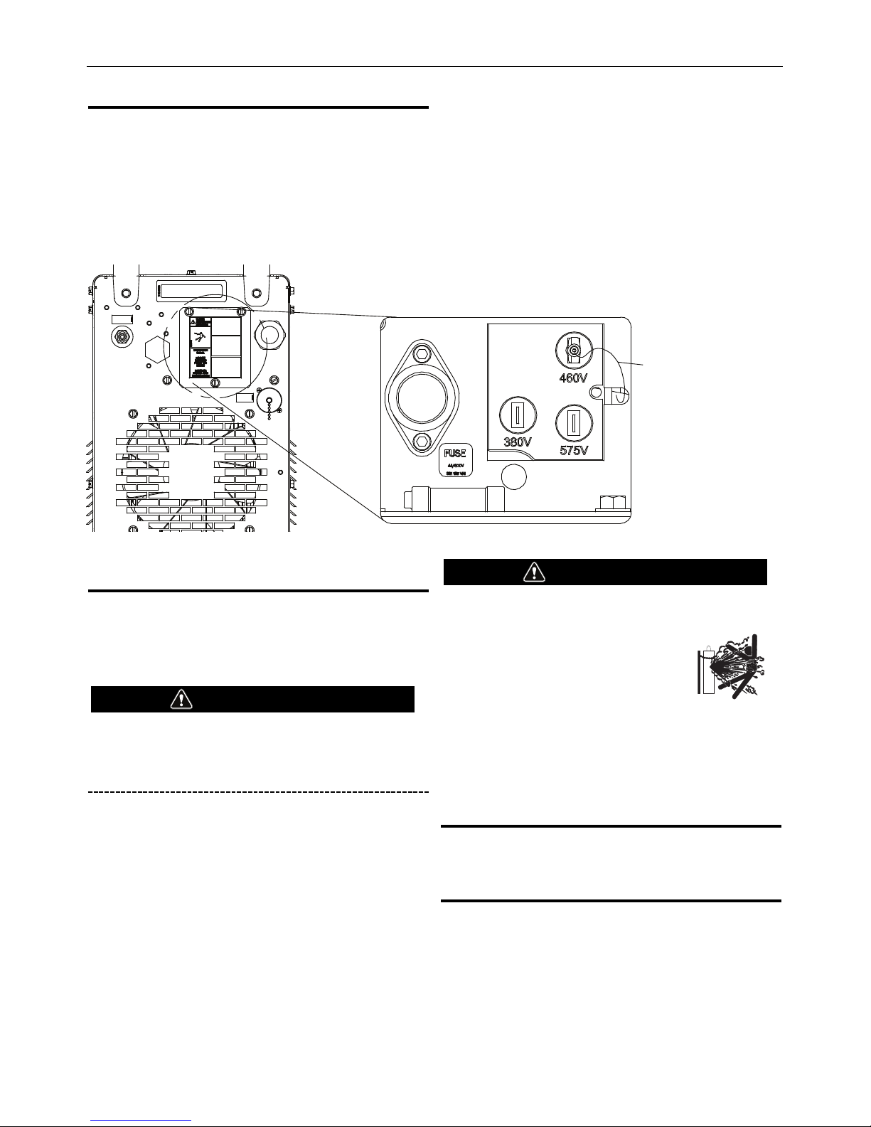
INPUT VOLTAGE SELECTION
The Flexcut™ 125 is shipped connected for 460 VAC input. To
reconfigure the machine for a different input voltage see the panel on
the rear of the unit (Figure A.2). With input power removed from the
m
achine, move the Auxiliary (“A”) lead from the 460V tap to the
desired input voltage. Always replace the cover when finished.
If the “A” lead is not connected to the proper voltage tap, the machine
may not power on, it may throw an error, or the fuse may open.
Should the fuse open, replace the fuse, reconnect the “A” lead to the
correct voltage and re-apply power.
GAS SUPPLY REQUIREMENTS
Supply the FLEXCUT™ 125 with clean, dry, oil-free compressed air or
nitrogen. A high pressure regulator MUST be used with a compressor
or a high pressure cylinder.
Supply pressure must be between 90-120 psi (6.21 - 8.27 bar) with
flow rates of at least 550 SCFH or 260 SLPM.
Air supply pressure should never exceed 130
psi or damage to the machine may occur!
The FLEXCUT™ 125 contains a built-in filter but depending on the
quality of the supply, additional filtration may be required. Be aware
that shop air systems are prone to oil and moisture contamination. If
shop air is used, it must be cleaned to ISO 8573-1:2010, Class 1.4.1.
See the Maintenance Gas Supply Section for information on changing
the internal filter element.
Specify dry air when using compressed cylinders. Breathing quality
air contains moisture and should not be used.
A standard nominal 5 micron inline filter is recommended, but for
optimal performance, select a pre-filter with a 3 micron absolute
rating.
CYLINDER could explode if damaged.
• Keep cylinder upright and chained to a fixed support.
• Keep cylinder away from areas where it
could be damaged.
• Never lift machine with cylinder
attached.
• Never allow the cutting torch to touch
the cylinder.
• Keep cylinder away from live electrical parts.
• Maximum inlet pressure 130 psi.
CONNECTING THE GAS SUPPLY
Air or gas must be supplied to the FLEXCUT™ 125 with 3/8” inside
diameter tubing and a ¼” NPT quick disconnect coupler.
OUTPUT CONNECTIONS
The FLEXCUT™ 125 is sent from the factory with a work clamp
included. The work clamp must be securely connected to the work
piece. If the work piece is painted or extremely dirty it may be
necessary to expose the bare metal in order to make a good electrical
connection.
WARNING
WARNING
A-4
I
NSTALLATION
F
LEXCUT™ 125
AUXILIARY ("A") LEAD
FIGURE A.2
Page 15
B-1
O
PERATION
OPERATION
SAFETY PRECAUTIONS
ELECTRIC SHOCK can kill.
• Do not touch electrically live parts
or electrode with skin or wet
clothing.
• Insulate yourself from work and
ground.
• Always wear dry insulating gloves.
FUMES AND GASES can be
dangerous.
• Keep your head out of fumes.
• Use ventilation or exhaust to
remove fumes from breathing zone.
WELDING, CUTTING and
GOUGING SPARKS can cause
fire or explosion
• Keep flammable material away.
• Do not weld, cut or gouge on
containers that have held combustibles.
ARC RAYS can burn.
• Wear eye, ear and body protection.
PLASMA ARC can injure
• Keep your body away from nozzle
and plasma arc.
• Operate the pilot arc with caution.
The pilot arc is capable of burning
the operator, others or even
piercing safety clothing.
Observe additional Safety Guidelines detailed in the beginning
of this manual.
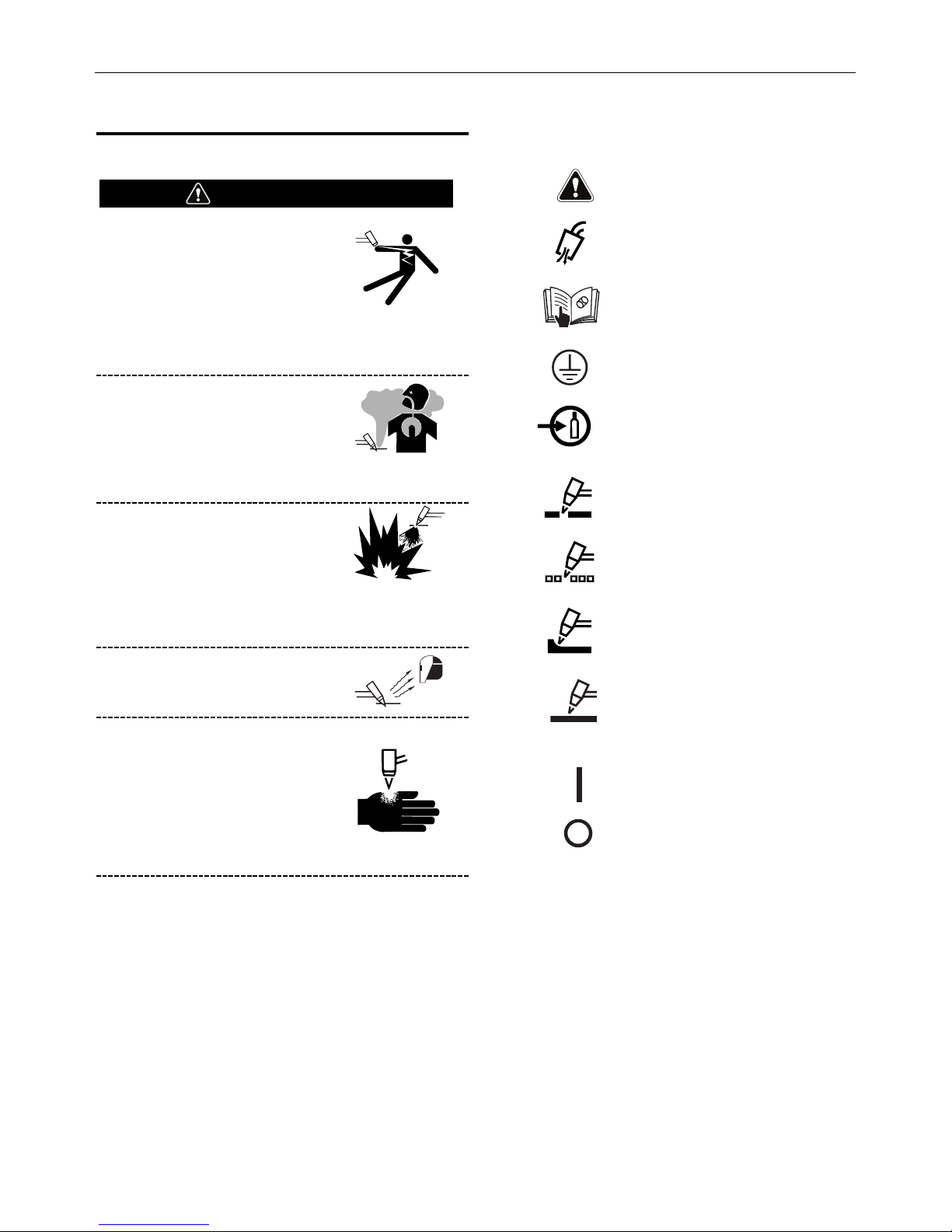
GRAPHIC SYMBOLS THAT APPEAR ON THIS
M
ACHINE OR IN THIS MANUAL
WARNING
FLEXCUT™ 125
WARNING OR CAUTION
READ INSTRUCTION
MANUAL
CUT
GAS INPUT
GRID or EXPANDED METAL
GOUGE
POWER ON
POWER OFF
PROTECTIVE
GROUND
GAS PURGE
MARKING
Page 16
B-2
CONTROLS AND SETTINGS
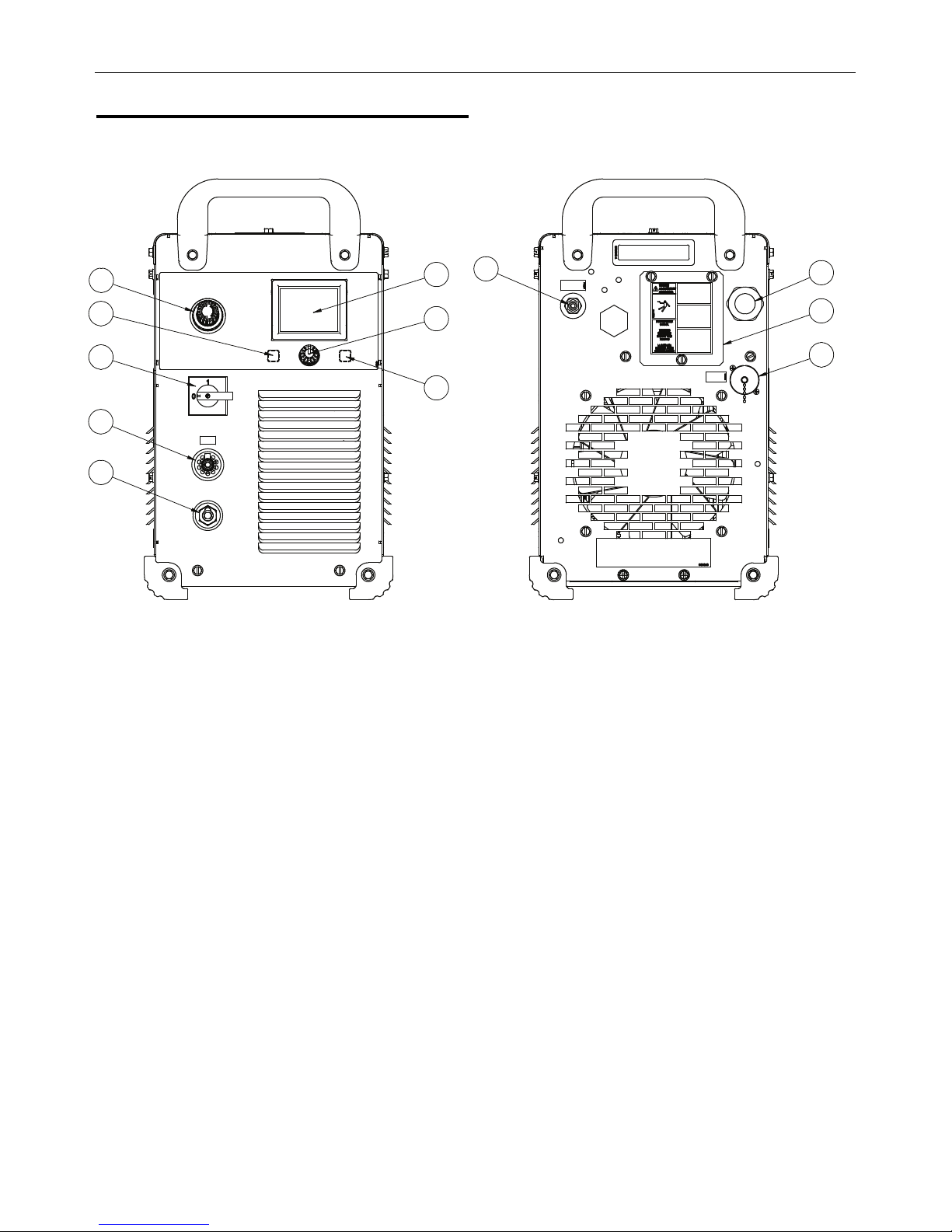
FIGURE B.2 - Front Panel
1. LCD Display: Shows available modes and real time parame-
ters.
2. Home Button: Allows the user to return to the Home Screen.
3. Menu Control Knob/Button: Used to navigate and select
items on the display.
4. Pressure Regulator: Allows the regulation of the primary
air/gas pressure.
5. Purge: Allows the user to enable air flow from the machine.
6. On/Off Switch: Turns the input power to the machine
ON/OFF.
7. Torch Connection: Connect the torch.
8. Work Lead Connection: Connect cable with work clamp.
FIGURE B.3 - Back Panel
9. Input Cord Strain Relief: Used to connect the unit to input
power.
10. Reconnect Panel Access: Allows the unit to be configured
for 380, 460, or 575 VAC input.
11. 14-pin CNC Interface: Allows access to Arc Start Trigger,
Arc Initiated contact, raw or divided Arc Voltage, and
Forced Mark.
12. Air or Gas Inlet (1/4” NPT Quick Connect): Compressed air
or gas connection.
FLEXCUT™ 125
O
PERATION
1
2
5
3
7
8
6
4
9
11
12
10
Page 17
B-3
O
PERATION
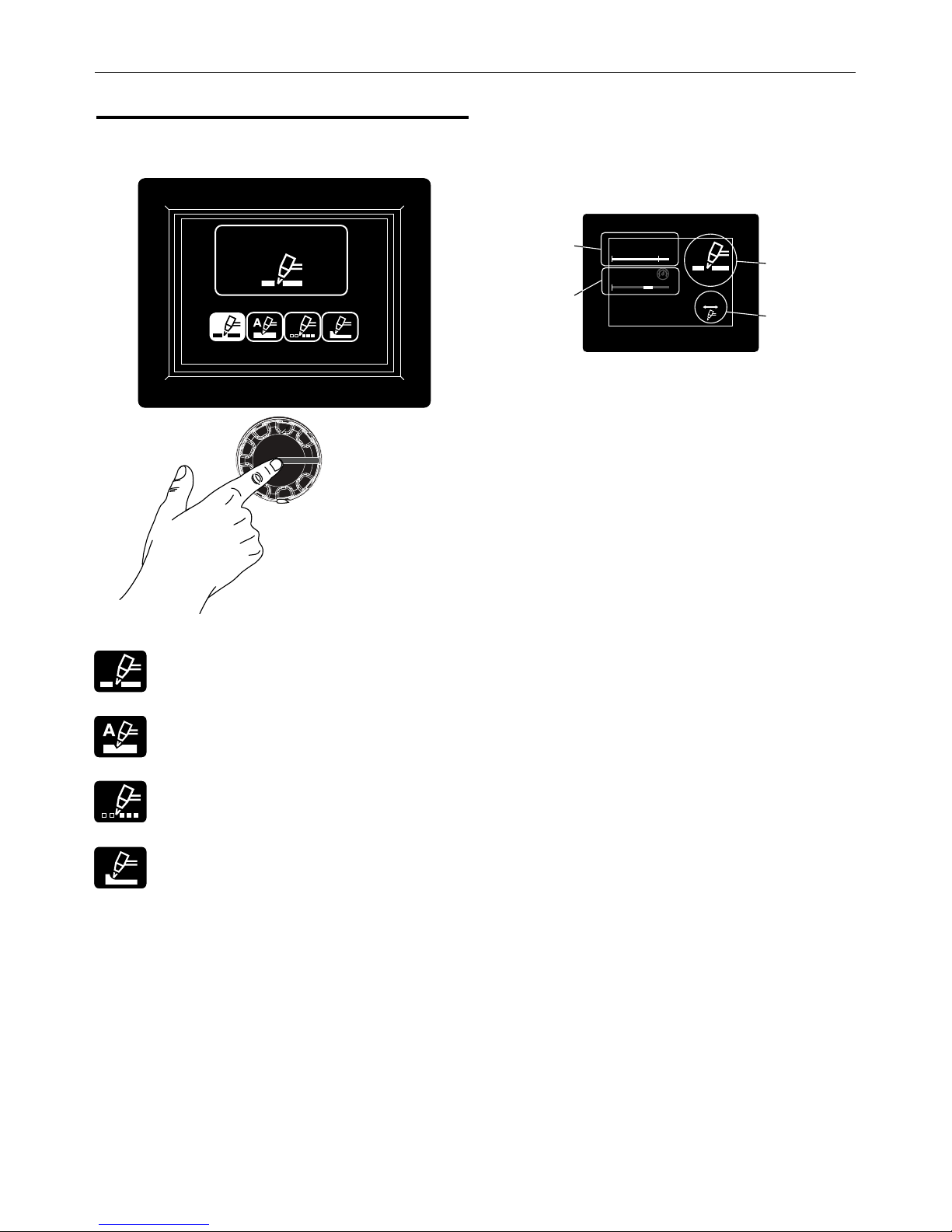
USER INTERFACE
Mode Select Screen
Choose between four available modes:
Cut – For cutting operations on a solid workpiece.
Mark – For discoloring or slight removal of material. Can
be used to add part numbers, bend lines, drill marks, or
many other surface modifications.
Grid – For cutting operations on a non-continuous
workpiece.
Gouge – For removing material from a workpiece
(removing a weld).
Active Mode Screen - See Figure B.4
Active Mode Icon – The currently selected mode icon will be
displayed here. Return to the mode select screen to choose a new
mode.
Output Current – Turn the control knob to adjust the desired output
current. While cutting, the screen will display the actual cutting
current in Amps. Output current range is dependent on Mode
selected.
Output Gas Pressure – The output gas pressure is displayed on a
linear scale, with the center of the green range as the recommended
output gas pressure based on selected mode and torch length. Use
the regulator knob on the front of the machine to adjust the output
gas pressure, but do so only while gas is flowing. Hold the purge
button while pulling and turning the regulator knob to adjust the
pressure as desired.
Torch Length – The selected torch length will be displayed here. Be
sure the torch length matches the torch that is being used with the
machine. The torch length can be modified in the settings menu.
FLEXCUT™ 125
Cutting
Press to Select
125
A
60
PSI
2
5ft
Active Mode Icon
Output Current
O
utput Gas Pressure
T
orch Length
F
IGURE B.4
Page 18
B-4
O
PERATION
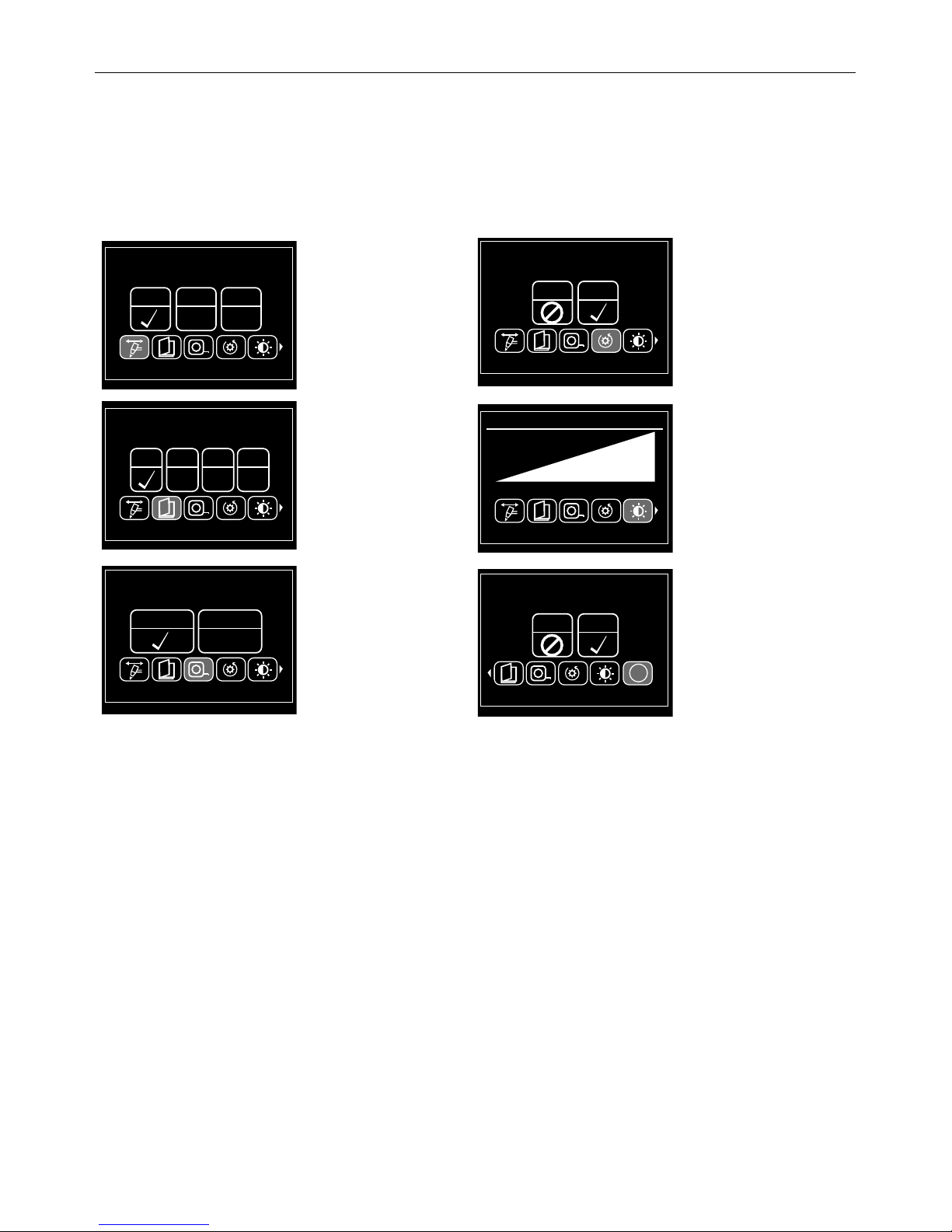
Settings
Press both the home and purge buttons at the same time to enter or
exit the settings menu.
Options (turn the knob to scroll and press the knob
to select):
Torch Size – Choose between
25 ft. (7.6m), 50 ft. (15.2m), or
75 ft. (22.9m) torch lengths.
This will change the
recommended output gas
pressure.
Language – Choose between
English, Spanish, French, or
German
Units – Choose between
English or Metric units
Reset Factory Settings – Use to
restore the machine back to the
factory settings
Brightness – Used to dim or
brighten the LCD display
Advanced – Used for diagnostic
purposes
FLEXCUT™ 125
25’
50’ 75’
P
ress to Select
Torch Size
EN SP FR GR
P
ress to Select
Language
English Metric
Press to Select
Units
No Yes
P
ress to Select
Reset Factory Settings
Press to Select
110
Brightness
10
No Yes
Press to Select
Information
i
Page 19
B-5
O
PERATION
FLEXCUT™ 125
MECHANIZED CUTTING
Mechanized Torch Installation
It is recommended that the FLEXCUT™ 125 mechanized torch be
i
nstalled on a positioner with an arc voltage control capable of
maintaining the cutting arc voltage within 1 volt. The positioner must
be rigid to ensure cut quality and a torch collision sensor is highly
recommended.
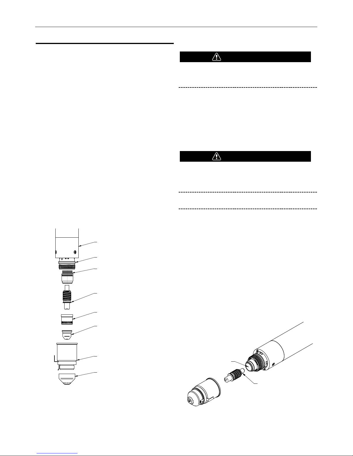
Installing the Mechanized Torch Consumables
To install the torch parts, perform the following
steps (See Figure B.5):
Note: Do not over tighten the consumables! Only tighten until the
parts are seated properly.
1. Inspect the threads on the torch body and retaining cap and
clean as necessary. Apply lubricant to the torch o-ring as
necessary. Lubricant should be oxygen safe and inert in a
flammable environment.
2. Install the electrode (1) into the torch body and press into place.
3. Thread the shield cap (5) onto the retaining cap assembly. (4)
4. Insert the nozzle (3) into the swirl ring. (2)
5. Place the swirl ring / nozzle assembly into the retaining cap.
6. Thread and tighten the retaining cap assembly onto the torch
body. (6)
Removing the Torch Consumables
Turn off the machine prior to removing
consumables.
To remove the torch consumables, perform the
following steps:
1. Remove the retaining cap from the torch.
2. Remove the swirl ring and nozzle from the retaining cap.
3. Separate the shield cap from retaining cap.
4. Remove the electrode from the torch body.
5. Remove the swirl ring from the nozzle.
Contaminants such as dirt, metallic dust, oil and moisture
present on the surface of the electrode and/or torch body
can cause electrical arcing between these components and
ultimately result in failure of the torch and consumables.
Do not continue to try and cut excessively worn
consumables as this can cause damage to the Torch Head.
In order to avoid damaging the torch and/or consumables, adhere to
the following guidelines:
1. Ensure that the air supplied to the torch does not contain contaminants such as debris, moisture and oil.
2. Ensure that the torch cathode body and electrode body are clean
prior to assembling the consumables into the torch. Wipe away any
contaminants with a dry, lint free cloth.
3. Be sure that the consumables are properly tightened and fully
inserted when installing them into the torch. Check the installation
of the consumables before the start of each work shift and
frequently to ensure that the parts have not become loose as a
result of normal operation.
4. Inspect the surfaces of the cathode body and electrode body to
ensure no contaminants have collected during operation.
(Reference Figure B.6)
FIGURE B.6
WARNING
WARNING
ELECTRODE BODY
CATHODE BODY
(1) ELECTRODE
BK14300-1
BK500024
(2) SWIRL RING
BK14300-13
(3) NOZZLE
45A - BK14300-7
65A - BK14300-8
85A - BK14300-9
105A - BK14300-10
125A - BK14300-11
(4) RETAINING CAP
BK14300-15
(5) SHIELD CAP
45A - 65A - BK14300-3
85A - 125A - BK14300-4
O-RING
BK14300-18
(7) FRONT ISOLATOR ASSEMBLY
(6) LC125M TORCH BODY
FIGURE B.5
Page 20

B-6
O
PERATION
Making a Cut
Setting up a Cut
Use the following procedure to make a cut with the
F
LEXCUT™ 125.
1
. Using the charts, determine the proper torch parts and cutting
conditions for the material being cut.
2. Install the proper consumables into the torch.
3. Turn the power switch to the ON position to apply power to the
FLEXCUT™ 125. The LCD will turn on and display the FLEXCUT™
initialization screen.
4. Press the home button and choose the desired operating mode.
5. Turn the control knob to set the desired output current.
6. Press and hold the gas purge button while adjusting the regulator
to recommended output pressure (center of green range).
7. The cutting operation is initiated after a start signal is received. The
arc should establish approximately 2 seconds after application of
the start command. The cutting operation is terminated when the
start signal is removed. At the completion of a cut, gas flow
through the torch will continue for approximately 20 seconds. The
LCD will display the actual output current and gas pressure while
the cut is active.
Machine Interface
The FLEXCUT™ 125 comes standard with a machine interface.
Interface signals provided include: Arc Start, Arc Initiated,
Arc Voltage (raw or divided) and Force Mark. These signals are
a
ccessible through the 14 pin connector on the case back. (See
Figure B.7
Arc Start:
The Arc Start circuit allows for triggering of the power source to
commence cutting. This circuit can be accessed through pins K and
M of the 14 pin connector. The circuit has a 15 VDC nominal open
circuit voltage and requires a dry contact closure to activate.
Arc Initiated:
The Arc Initiated circuit provides information as to when a cutting arc
has transferred to the work piece. This circuit can be accessed
through pins I and J of the 14 pin connector. The circuit provides a
dry contact closure when the arc has transferred. Input to this circuit
should be limited to 0.3 A for either 120VAC or 30VDC.
Arc Voltage:
The Arc Voltage circuit can be used for activating a torch height
control. This circuit can be accessed through pins D and G of the 14
pin connector. The circuit provides full electrode to work arc voltage
(300VDC maximum). A divided arc voltage of 20:1, 30:1, 40:1 or 50:1
is available. See “Accessing Divided Arc Voltage.”
Force Mark:
The Force Mark circuit can be used to change between a cut or grid
operating mode and a marking mode quickly and while output is on.
This circuit can be accessed though pins A and B of the 14-pin
connector. This circuit requires a dry contact closure to operate and
both modes should be configured prior to cutting.
Users wishing to utilize the Machine Interface can order a K867
Universal Adapter (please adhere to the pin locations stated above) or
manufacture a 14 pin connector cable assembly.
FLEXCUT™ 125
14-PIN BOX RECEPTAC
LE,
FRO
N
T
V
IEW
Arc Star
t
Force Mark
Arc Voltage
A
rc
Initia
ted
J
I
H
N
G
F
E
D
C
L
M
K
A
B
FIGURE B.7
Page 21

B-7
O
PERATION
Cutting Charts
The cutting charts shown on the following pages are intended to give
t
he operator the best starting point to use when making a cut on a
particular material type and thickness. Small adjustments may have
to be made to achieve the best cut. Also, remember that the arc
voltage must be increased as the electrode wears in order to maintain
the correct cutting height.
FLEXCUT™ 125
C
URRENT
P
AGE
45 AMPS B-8
65 AMPS B-9
85 AMPS B-10
105 AMPS B-11
125 AMPS B-12
Page 22

!"#$%&#%'()*+,-'.#/),'0.#(1+/2%*30'/
4,0.#56''0
78'//28'
7,'8('#
9
'0*:
!! "#$ #%& $' !! $' !! ()*
+,&-
./0123%
()*
+,&-
./0123%
$' !!
45-32 67689 67: ;:6 8;: :66 8;< 676<: 878
44-32 676;6 679 ;56 8;: <56 8;< 676<: 878
8
9-32 676<9 874 ;:6 8;: <86 8;< 676:6 87;
85-32 67656 87: ;4: 8;: <66 8;< 676:6 87;
8<-32 676=: 87> 67;6 4>6 8<6 ;4: 8;> 67656 87:
84-32 6786: 47= 466 8<4 446 8;> 6765: 87=
86-32 678;: ;7< 886 8<< 85= 8<4 6765: 87=
;?85 67899 <79 67:6 96 8<5 886 8<; 6765: 87=
8?< 674:6 57< 6756 6784 ;76 <: 8:4 =; 8:6 67696 476
@-45@86-32-#1%%0-$#-&/0A-,/00%AB-;?85-2'A-8?<-$'-#1%%0-$#-C/1-,/00%A
56*,+0'//#56''0
78'//28'
7,'8('#
9'0*:
!! "#$ #%& $' !! $' !! ()*
+,&-
./0123%
()*
+,&-
./0123%
$' !!
45-32 6768> 67: <66 8:6 :86 8:6 676<6 876
44-32 676;8 679 ;=: 8:6 <=: 8:6 676;6 679
89-32 676:6 87; ;:6 8:6 <66 8:4 676;: 67>
85-32 6765; 875 ;8: 8:4 <66 8:4 676<6 876
8<-32 676=9 476 6746 4<6 8:< 4:6 8:< 676<: 878
84-32 6786> 479 67;6 8=: 8:5 89: 8:< 676:6 87;
86-32 678<8 ;75 67<6 866 8:5 8<6 8:< 676:: 87<
;?85 67899 <79 67:6 =6 8:9 9: 8:5 67656 87:
8?< 674:6 57< 6756 ;6 8:> <6 8:= 67656 87:
$02%,+2%
78'//28'
7,'8('#
9'0*:
!! "#$ #%& $' !! $' !! ()*
+,&-
./0123%
()*
+,&-
./0123%
$' !!
8?;4 676;8 679 6766 ;56 8:4 <:6 8:4 676:: 87<
8?85 6765; 875 6786 ;56 8:< ;>6 8:< 67656 87:
;?;4 676>< 47< 6746 4;: 8:5 ;66 8:4 67656 87:
8?9 6784: ;74 67<6 896 856 46: 8:9 6765: 87=
8?< 674:6 57< 67:6 6785 <78 :: 854 =: 856 6765: 87=
4*8;,+<
78'//28' =288'+6
"#$ +!"# $' !! $' !!
84 6786 47:< 6786 47:<
84 6786 47:< 6786 47:<
84 6786 47:< 6786 47:<
8==
7,'8('#9'0*:
#%&
6766
6766
6766
./01#
8==
4:6
8==
781.2(6,1+#5'66,+</
=266,+<#>',<)6
7,'8('#>',<)6
781.2(6,1+#5'66,+</
*$0A-D1%%0
D12$'0%##-D1%%0
+0E!$'E!
?8*@'0#5&''.
F+00-GC$&H'%##%#I
()*
4:6
4:6
;=J
4*6'8,*0
$8(#A106*<'
7,'8('#>',<)6
=266,+<#>',<)6
B'8C#D,.6)
676<
876
E&6,%2%#5'66,+</
B'8C#D,.6)
6786
47:
67<6
6786
6766
6769
4*6'8,*0#?),(;+'//
=266,+<#>',<)6
6785
<78
56J
6786
47:
4*6'8,*0#?),(;+'//
@-K/,-<:+-&E11$'3-/L-D12$'0%##-D1%%0-M$1C-2-=:-L17-1/,&CB-!$'$!E!-$'"E1-32#-",%##E,%-$#-866-"#$7
$'
E&6,%2%#5'66,+</
7,'8('#>',<)6
B'8C#D,.6)
$'
6786
47:
6746
:78
=6J
6766
6786
476
4*6'8,*0#?),(;+'//
E&6,%2%#5'66,+</
781.2(6,1+#5'66,+</
=266,+<#>',<)6
7,'8('#>',<)6
$'
6746
674:
57<
:78
56J
B-8
O
PERATION
FLEXCUT™ 125
Shield Retaining Cap Nozzle Swirl Ring Electrode
BK14300-3 BK14300-15 BK14300-7 BK14300-13 BK14300-1
LC125M Torch Body
* Listed Gas Pressures are for 25 ft. torches. Increase Gas Pressure by 5 psi
for each additional 25 ft. of torch length.
Explosion Hazard
Do not cut Aluminum over water tables
WARNING
Page 23

B-9
O
PERATION
FLEXCUT™ 125
!"#$%&#%'()*+,-'.#/),'0.#(1+/2%*30'/
4
,0.#56''0
78'//28'
7
,'8('#
9'0*:
!
!"#$ #%& $'!!$'!!()*
+,&-
.
/0123%
(
)*
+,&-
.
/0123%
$
'!!
45-32 67656 478 6746 986 4:; 9<8 4:4 67656 478
4
6-32 674;8 ;7: 67;6 4<8 4:8 995 4:; 676=6 47>
;?45 674>> :7> 6786 4:6 4:8 4=6 4:; 676=6 47>
4?: 67986 57: 67>6 <8 4:8 448 4:; 676=6 47>
;
?> 67;=8 <78 4796 86 489 5; 4:> 676=8 47<
4
?9 67866 497= 679 874 ;8 48; :6 486 676>8 979
8?> 67598 487< 67; =75 96 485 9: 488 676>8 979
;?: 67=86 4<74 48 459 4< 456 676<6 97; @%#
=?> 67>=8 9979 46 458 4: 45: 676<6 97; @%#
447666987: = 4=6 46 455676<997; @%#
A-45-2'B-46-32-#1%%0-$#-&/0B-,/00%BC-;?45-A-4-$'-#1%%0-$#-D/1-,/00%B
56*,+0'//#56''0
78'//28'
7,'8('#
9'0*:
!! "#$ #%& $' !! $' !! ()*
+,&-
./0123%
()*
+,&-
./0123%
$' !!
45-32 6765; 475 ;98 4:< :98 4:< 67686 47;
46-32 674:4 ;75 946 484 95: 4:< 67656 478
;?45 674>> :7> 6796 4:= 48; 45> 484 676=6 47>
4?: 67986 57: 67:6 =6 488 <6 48; 676>6 976
;?> 67;=8 <78 67>6 :; 48> 86 48= 676<6 97;
4?9 67866 497= 4796 96 45= ;9 48< 67466 978
8?> 67598 487< 4< 458 99 45; 67468 97= @%#
;?: 67=86 4<74 4: 45> 4> 455 67446 97> @%#
$02%,+2%
78'//28'
7,'8('#
9'0*:
!! "#$ #%& $' !! $' !! ()*
+,&-
./0123%
()*
+,&-
./0123%
$' !!
4?45 6765; 475 6746 ;:8 456 :9> 456 676=6 47>
4?> 67498 ;79 6796 988 486 ;98 486 67656 478
4?: 67986 57: 67:6 466 456 4:= 48< 676=8 47<
;?> 67;=8 <78 6756 88 458 =6 45; 676>8 979
4?9 67866 497= 4766 ;8 45> :8 45> 676<6 97;
8?> 67598 487< 99 4=6 ;6 45> 67466 978 @%#
;?: 67=86 4<74 4: 4=: 99 4=9 67468 97= @%#
4*8;,+<
78'//28' =288'+6
"#$ +!"# $' !! $' !!
4: 6746 978: 6746 978:
4: 6746 978: 6746 978:
4: 6746 978: 6746 978:
>'8?#@,.6)
A.<'#
5
6*86
./01#
$8(#B106*<'
>'8?#@,.6)
4=>
*$0B-E1%%0
7,'8('#C',<)6
>'8?#@,.6)
4*6'8,*0#D),(;+'//
781.2(6,1+#5'66,+</
=266,+<#C',<)6
6749
;76
$
'
E&6,%2%#5'66,+</
9766
56F
E12$'0%##-E1%%0
4=>
A.<'#
56*86
A.<'#
56*86
4=>
+0G!$'G!
D8*F'0#5&''.
H+00-ID$&J'%##%#K
()*
986
4*6'8,*0
986
;=F
7,'8('#C',<)6
=266,+<#C',<)6
6766
986
7,'8('#9'0*:
#%&
6766
6766
6746
4*6'8,*0#D),(;+'//
E&6,%2%#5'66,+</
781.2(6,1+#5'66,+</
=266,+<#C',<)6
7,'8('#C',<)6
$'
67;;
>7;
6796
874
6756
56F
$'
6796
874
4*6'8,*0#D),(;+'//
E&6,%2%#5'66,+</
=75
6798
57:
56F
781.2(6,1+#5'66,+</
=266,+<#C',<)6
7,'8('#C',<)6
6786
6745
:74
679
874
67;6
Shield Retaining Cap Nozzle Swirl Ring Electrode
BK14300-3 BK14300-15 BK14300-8 BK14300-13 BK14300-1
L
C125M Torch Body
* Listed Gas Pressures are for 25 ft. torches. Increase Gas Pressure
by 5 psi for each additional 25 ft. of torch length.
Explosion Hazard
Do not cut Aluminum over water tables
WARNING
Page 24

!"#$%&#%'()*+,-'.#/),'0.#(1+/2%*30'/
4,0.#56''0
78'//28'
7,'8('#
9'0*:
!! "#$ #%& $' !! $' !! ()*
+,&-
./0123%
()*
+,&-
./0123%
$' !!
45 56478 769 5655 :;5 47< 748 47= 56585 46:=
7>4; 564<< 96< 56:5 4?5 495 ::5 47? 5658< 469=
4>9 56:85 ;69 4:5 494 488 495 565;5 468:
7>< 567=8 ?68 =8 499 << 497 565;< 46=7
4>: 56855 4:6= 95 498 89 498 565=< 46?<
8>< 56;:8 486? 4655 75 485 95 49= 565<8 :64;
7>9 56=85 4?64 4685 5675 =6; :9 487 75 485 565<8 :64;
=>< 56<=8 ::6: 46:8 4; 48< :: 487 565?5 :6:? @%#
446555:869 47 4;5 4; 48;56455:689 @%#
4-4>9 46:85 746< = 4;< 45 4;4 56445 :6=? @%#
A-45-32-#1%%0-$#-&/0B-,/00%BC-7>4;-A-4-4>9-$'-#1%%0-$#-D/1-,/00%B
56*,+0'//#56''0
78'//28'
7,'8('#
9'0*:
!! "#$ #%& $' !! $' !! ()*
+,&-
./0123%
()*
+,&-
./0123%
$' !!
45 56494 76; 56:5 :<8 47? 798 47< 565=8 46?4
7>4; 564<< 96< 5675 :45 47? :85 47< 565=8 46?4
4>9 56:85 ;69 5695 478 47? 4=5 47< 565<5 :657
7>< 567=8 ?68 5685 ;5 497 <5 49: 565<5 :657
4>: 56855 4:6= 56=5 7; 49< 9; 49; 565<9 :647
8>< 56;:8 486? :; 485 77 49? 565?7 :67;
7>9 56=85 4?64 4< 489 :9 487 56458 :6;= @%#
=>< 56<=8 ::6: 4; 488 4? 489 56458 :6;= @%#
446555:869 44 48? 49 48<56458:6;= @%#
$02%,+2%
78'//28'
7,'8('#
9'0*:
!! "#$ #%& $' !! $' !! ()*
+,&-
./0123%
()*
+,&-
./0123%
$' !!
4>< 564:8 76: 56:5 745 489 7;5 489 565<8 :64;
4>9 56:85 ;69 5695 495 48< 4;= 48< 565?5 :6:?
7>< 567=8 ?68 56;5 =8 4;5 459 48< 565?8 :694
4>: 56855 4:6= 56<5 88 4;: =7 4;: 56455 :689
8>< 56;:8 486? 4655 7< 4;= 9< 4;= 56458 :6;=
7>9 56=85 4?64 :< 4;? 95 4;= 56458 :6;= @%#
=>< 56<=8 ::6: :: 4=: 75 4=4 56458 :6;= @%#
446555:869 48 4=8 :5 4=856458:6;= @%#
4*8;,+<
78'//28' =288'+6
"#$ +!"# $' !! $' !!
47 5645 :689 5645 :689
49 5645 :689 5645 :689
49 5645 :689 5645 :689
4<<
>.<'#
56*86
>.<'#
56*86
>.<'#
56*86
56<5
;64
56:9
7,'8('#9'0*:
#%&
5655
5655
5655
./01#
$8(#?106*<'
7,'8('#@',<)6
=266,+<#@',<)6
4<<
:85
4<<
*$0B-E1%%0
E12$'0%##-E1%%0
A8*B'0#5&''.
F+00-GD$&H'%##%#I
()*
:85
4*6'8,*0
:85
7,'8('#@',<)6
+0J!$'J!
5677
<67
7,'8('#@',<)6
$'
$'
7=K
;5K
C'8D#E,.6)
4*6'8,*0#A),(;+'//
4*6'8,*0#A),(;+'//
F&6,%2%#5'66,+</
781.2(6,1+#5'66,+</
=266,+<#@',<)6
$'
5685
4685
5
6:8;69
56:8
;69
=266,+<#@',<)6
7,'8('#@',<)6
F&6,%2%#5'66,+</
564:
765
56:4
867
=266,+<#@',<)6
C'8D#E,.6)
4*6'8,*0#A),(;+'//
F&6,%2%#5'66,+</
781.2(6,1+#5'66,+</
;5K
56:8
;69
5685
;5K
564:
765
C'8D#E,.6)
781.2(6,1+#5'66,+</
B-10
FLEXCUT™ 125
O
PERATION
Retaining Cap Nozzle Swirl Ring Electrode
BK14300-15 BK14300-9 BK14300-13 BK14300-1
S
hield
B
K14300-4
LC125M Torch Body
L
* Listed Gas Pressures are for 25 ft. torches. Increase
Gas Pressure by 5 psi for each additional 25 ft. of torch
length.
Explosion Hazard
Do not cut Aluminum over water tables
WARNING
Page 25

B-11
O
PERATION
FLEXCUT™ 125
$ $ $ $
5-1/$67((1
89(0039(
8-(9)($
:(1+;
!! "#$ #%& $' !! $' !! ()*
+,&-
./0123%
()*
+,&-
./0123%
$' !!
456 789:7 ;86 7867 4:7 46: 4<7 46: 78477 98:
=5< 78=>: ?8: 78:7 47: 46> 446 46; 78477 98:
459 78:77 498> 78;7 ;7 4:7 >= 4:7 7847: 98>
:5< 78;9: 4:8? 69 4:= :7 4:7 7847: 98>
=56 78>:7 4?84 == 4:6 => 4:9 7847: 98>
>5< 78<>: 9989 9877 9: 4:; =4 4:: 78447 98<
4487779:86 48<7 4? 4;7 9= 4:?78497=87 @%#
4-456 489:7 =48< 9877 46 4;: 4; 4;6 7849: =89 @%#
A-+00-B/1-,/00%C-#1%%0
67+-,1(00$67((1
89(0039(
8-(9)($
:(1+;
!! "#$ #%& $' !! $' !! ()*
+,&-
./0123%
()*
+,&-
./0123%
$' !!
456 789:7 ;86 78=7 >8; 4?< 4:< 94: 46: 78477 98:
=5< 78=>: ?8: ?7 4:7 479 46< 7847: 98 >
459 78:77 498> :: 4:= ;? 46? 7847: 98>
:5< 78;9: 4:8? 4897 7867 4789 =< 4;; 69 4:; 7844: 98?
=56 78>:7 4?84 786= 478< 9; 4;7 =7 4:< 78497 =87
>5< 78<>: 9989 94 4;: 9: 4:? 78499 =84 @%#
4487779:86 4> 4>6 97 4;=784=7=8= @%#
4-456 489:7 =48< 98:7 44 4;< 46 4;; 784=7 =8= @%#
%13&-,3&
89(0039(
8-(9)($
:(1+;
!! "#$ #%& $' !! $' !! ()*
+,&-
./0123%
()*
+,&-
./0123%
$' !!
456 789:7 ;86 78:7 947 4:7 99: 46? 78477 98:
=5< 78=>: ?8: 78;7 47: 4:: 4=7 4:6 7847: 98>
459 78:77 498> 78<7 >> 4:< ?= 4:; 78447 98<
:5< 78;9: 4:8? 4877 78=< ?8: :6 4;= ;9 4;9 78447 98<
=56 78>:7 4?84 4897 =< 4;> 64 4;; 7844: 98?
>5< 78<>: 9989 48=: 9? 4;? =6 4;< 7844: 98?
4487779:86 9= 4>9 9? 4>778497=87 @%#
4-456 489:7 =48< 4: 4>? 4< 4>> 78497 =87 @%#
5+9<-,=
89(0039( >399(,7
"#$ +!"# $' !! $' !!
46 7847 98:6 7847 98:6
4: 7847 98:6 7847 98:6
4: 7847 98:6 7847 98:6
4<6
?/=($
67+97
?/=($
67+97
?/=($
67+97
./01#
%9)$@217+=(
4<6
9:7
4<7
784<
68;
>377-,=$A(-=*7
+0D!$'D!
B9+C(1$6'((/
E+00-FB$&G'%##%#H
()*
9:7
5+7(9-+1
9:7
=>I
*$0C-J1%%0
J12$'0%##-J1%%0
7877
7877
8-(9)($:(1+;
#%&
7877
8-(9)($A(-=*7
4877
78=:
<8?
78==
<8=
78=:
<8?
784<
68;
>377-,=$A(-=*7
789<
>84
78=<
?8:
78=7
>8;
D'7-&3&$6(77-,=0
E(9F$G-/7*
892/3)7-2,$6(77-,=0
48<7
78=:
<8?
E(9F$G-/7*
D'7-&3&$6(77-,=0
892/3)7-2,$6(77-,=0
>377-,=$A(-=*7
E(9F$G-/7*
D'7-&3&$6(77-,=0
892/3)7-2,$6(77-,=0
>377-,=$A(-=*7
784;
684
$'
5+7(9-+1$B*-)<,(00
7867
4789
8-(9)($A(-=*7
9877
78;7
$'$'5+7(9-+1$B*-)<,(00
8-(9)($A(-=*7
5+7(9-+1$B*-)<,(00
;7I
;7I
;7I
8-(9)($A(-=*7
$$ $ $
(14+&30,2)/1(-*0/(.-,+*)(&'%&#"!
$$ $ $
0(
$$ $ $
$$ $ $
$$ $ $
$$ $ $
$$ $ $
$$ $ $
$$ $ $
$$ $ $
Retaining Cap Nozzle Swirl Ring Electrode
BK14300-15 BK14300-10 BK14300-13 BK14300-1
S
hield
BK14300-4
LC125M Torch Body
* Listed Gas Pressures are for 25 ft. torches. Increase Gas Pressure
by 5 psi for each additional 25 ft. of torch length.
Explosion Hazard
Do not cut Aluminum over water tables
WARNING
Page 26

!"#$%&'$&()*+,-.(/$0*-(1/$)2,03&+41(0
5-1/$67((1
89(0039(
8-(9)($
:(1+;
!! "#$ #%& $' !! $' !! ()*
+,&-
.
/0123%
()*
+,&-
.
/0123%
$' !!
456 789:7 ;86 78<7 4=7 46: 947 466 78477 98:
<5= 78<>: ?8: 78:7 447 46> 49= 46; 7847: 98>
459 78:77 498> 78>7 >9 46? == 46> 7847: 98>
:5= 78;9: 4:8? 4877 :7 4:4 ;< 4:7 78447 98=
<56 78>:7 4?84 4897 78<< =8< 67 4:< :9 4:9 78447 98=
>5= 78=>: 9989 48=7 78<: =8? <4 4:; 67 4:: 7844: 98?
4487779:86 98:778<=?8: 9< 4;7 <9 4:>78497<87
4-456 489:7 <48= 4; 4;< 94 4;9 7849: <89 @%#
4
-459 48:77 <=84 44 4;= 46 4;= 7849: <89 @%#
A-+00-B/1-,/00%C-#1%%0
67+-,1(00$67((1
89(0039(
8-(9)($
:(1+;
!! "#$ #%& $' !! $' !! ()*
+,&-
./0123%
()*
+,&-
./0123%
$' !!
456 789:7 ;86 99: 46; 9;7 46= 78477 98:
<5= 78<>: ?8: 47> 46= 4:9 46= 78447 98=
459 78:77 498> 78;7 >= 4:< ?6 4:7 78447 98=
:5= 78;9: 4:8? 78>7 6> 4:: ;7 4:< 7844: 98?
<56 78>:7 4?84 4897 67 4:> 6: 4:; 7844: 98?
>5= 78=>: 9989 48:7 9; 4;4 <9 4:? 7844> <87 @%#
4487779:86 48=7 4? 4;; 9: 4;<78497<87 @%#
4-456 489:7 <48= 9877 46 4;= 4= 4;: 7849: <89 @%#
4-459 48:77 <=84 9897 ? 4>: 44 4>9 7849: <89 @%#
%13&-,3&
89(0039(
8-(9)($
:(1+;
!! "#$ #%& $' !! $' !! ()*
+,&-
./0123%
()*
+,&-
./0123%
$' !!
456 789:7 ;86 7897 9:7 4:7 9>: 46? 7844: 98?
<5= 78<>: ?8: 7867 49= 4:6 4:= 4:9 78497 <87
459 78:77 498> 78:7 =< 4:> 449 4:6 78497 <87
:5= 78;9: 4:8? 78>7 78<< =8< ;< 4;4 =< 4:? 78497 <87
<56 78>:7 4?84 4877 78<: =8? :9 4;6 ;9 4;9 7849: <89
>5= 78=>: 9989 48;7 7867 4789 <6 4;> 6; 4;6 7849> <89
4487779:86 9897786<478= <9 4>7 67 4;>784<7<8<
4-456 489:7 <48= 4> 4>= <7 4>< 784<7 <8< @%#
4-459 48:77 <=84 49 4=< 4; 4=7 78467 <8; @%#
5+9<-,=
89(0039(
>399(,7
"#$ +!"# $' !! $' !!
4: 7847 98:6 7847 98:6
4: 7847 98:6 7847 98:6
4; 7847 98:6 7847 98:6
?/=($
67+97
?/=($
67+97
?/=($
67+97
7877
78:7
8-(9)($:(1+;
@9+A(1$6'((/
%9)$B217+=(
8-(9)($C(-=*7
>377-,=$C(-=*7
()*
./01#
4>>
4=6
4>?
9:7
5+7(9-+1
*$0C-D1%%0
D12$'0%##-D1%%0
+0E!$'E!
F+00-GB$&H'%##%#I
D(9E$F-/7*
784;
684
78<7
>8;
78<7
>8;
892/3)7-2,$6(77-,=0
G'7-&3&$6(77-,=0
5+7(9-+1$@*-)<,(00
G'7-&3&$6(77-,=0
892/3)7-2,$6(77-,=0
>377-,=$C(-=*7
8-(9)($C(-=*7
$'
9897
5+7(9-+1$@*-)<,(00
>377-,=$C(-=*7
8-(9)($C(-=*7
;7J
$'$'D(9E$F-/7*
98:7
5+7(9-+1$@*-)<,(00
G'7-&3&$6(77-,=0
892/3)7-2,$6(77-,=0
>377-,=$C(-=*7
8-(9)($C(-=*7
7897
:84
7897
:84
78<7
>8;
7867
;7J
;7J
<>J
D(9E$F-/7*
4789
>8;
78<:
=8?
78<7
78<7
>8;
9:7
#%&
7877
7877
9:7
B-12
O
PERATION
FLEXCUT™ 125
Retaining Cap Nozzle Swirl Ring Electrode
B
K14300-15 BK14300-11 BK14300-13 BK14300-1
BK14300-4
Shield
LC125M Torch Body
%% % %
(#D-320/>+$#(":0$(C"/-:+(3=13BA@
%% % %
0(
%% % %
%% % %
%% % %
%% % %
%% % %
%% % %
%% % %
%% % %
* Listed Gas Pressures are for 25 ft. torches. Increase Gas
Pressure by 5 psi for each additional 25 ft. of torch length.
Explosion Hazard
Do not cut Aluminum over water tables
WARNING
Page 27

B-13
O
PERATION
CONSUMABLE LIFE
Use the following guidelines to maximize consumable parts life:
1. The FLEXCUT™ 125 utilizes the latest advancement in
technology for extending the life of the torch consumable parts.
To maximize the life of the consumable parts, it is imperative
t
hat the shutdown procedure of the arc is carried out properly.
The arc must be extinguished while it is still attached to the
workpiece. A popping noise may be heard if the arc extinguishes
abnormally. Note that holes are usually programmed without
lead-outs to prevent loss of the arc during shutdown.
2. Use the recommended pierce height given in the cutting charts. A
pierce height that is too low will allow molten metal that is
ejected during the piercing process to damage the shield cap
and nozzle. A pierce height that is too high will cause the pilot
arc time to be excessively long and will cause nozzle damage.
3. Minimize firing the torch in the air. Nozzle damage will occur.
4. Make sure the torch does not touch the plate while cutting.
Shield cap and nozzle damage will result.
5. Use a chain cut when possible. Starting and stopping the torch is
more detrimental to the consumables than making a continuous
cut.
CUT QUALITY
Before the optimum cutting condition can be achieved on a particular
material type and thickness, the machine operator must have a
thorough understanding of the cutting characteristics of the
F
LEXCUT™ 125. When the cut quality is not satisfactory, the cutting
speed, torch height, or gas pressures may need to be adjusted in
small increments until the proper cutting condition is obtained. The
following guidelines should be useful in determining which cutting
parameter to adjust.
Before making any parameter changes, verify that the torch is
square to the work piece. Also, it is essential to have the correct
torch parts in place and to ensure that they are in good
condition. Check the electrode for excessive wear and the nozzle
and shield cap orifices for roundness. Also, check the parts for
any dents or distortions. Irregularities in the torch parts can
cause cut quality problems.
1. A positive cut angle (top dimension of piece smaller than the
bottom dimension) usually occurs when the torch standoff
distance is too high, when cutting too fast, or when excessive
power is used to cut a given plate thickness.
2. A negative cut angle (top dimension of piece larger than the
bottom dimension) usually occurs when the torch standoff
distance is too low or when the cutting speed is too slow.
3. Top dross usually occurs when the torch standoff distance is too
high.
4. Bottom dross usually occurs when the cutting speed is either too
slow (slowspeed dross) or too fast (high-speed dross). Lowspeed dross is easily removed, while high-speed dross usually
requires grinding or chipping off. Bottom dross also occurs more
frequently as the metal heats up. As more pieces are cut out of a
particular plate, the more likely they are to form dross.
5. Note that different material compositions have an effect on dross
formation.
6. If the material is not being completely severed, the likely causes
are that the cutting current is too low, the travel speed is too
high, the gas pressure is incorrect, the incorrect consumables
are installed in the torch, or the consumables are worn.
FLEXCUT™ 125
Page 28

B-14
O
PERATION
FLEXCUT™ 125
INSPECTION OF CONSUMABLE PARTS
When the cut quality is not satisfactory, use the following guidelines
for determining which consumable parts need to be changed.
I
nspect all parts for dirt or debris and clean as necessary.
!"#$ %&'!()$*+,# ),##()$%-(*")$%,&
!"#$%&'()*
+$,)#-#-.'()*
-/00%$
!1#+%'+#-.
$%$(,+/&$
,/+("
&)2).$&3'1/+-3'/+'&+4'/5+#-.
*)+,!'#-'*%)($'*#-!')+$'(%$)-'
)-&'2/6$'#-')-&'/7,'$)!#%4
8$$*'*#-!')!'(%$)-')!'*/!!#9%$:'#;',"$4'-/'
%/-.$+'2)8$'.//&'(/-,)(,'1#,"'
+$,)#-#-.'()*',"$4'27!,'9$'+$*%)($&:
#;',"$'/5+#-.'#!'&)2).$&'/+'(+)(8$&3'
+$*%)($'#,:')**%4')'!#%#(/-$'9)!$&'
%79+#()-,',/',"$'/5+#-.')!'-$$&$&',/'
*+/%/-.'%#;$:
($-,$+'"/%$'/7,'/;'+/7-&
+$*%)($'-/00%$
+$*%)($'-/00%$
9%/1'/7,'1#,"'(/2*+$!!$&')#+:'+$*%)($'
*)+,'#;'"/%$!'()--/,'9$'(%$)+$&:
(%/..$&'"/%$!
&)2).$
+$*%)($'!1#+%'+#-.
*#,'&$*,"
!7+;)($')+(#-.'/+'$+/!#/-
+$*%)($'$%$(,+/&$'#;'!7+;)($'#!'$<($!!#6$%4'
(/++/&$&:
+$*%)($'$%$(,+/&$'#;'($-,$+'*#,'&$*,"'#!'
.+$),$+',")-':=>=?'@A:B'CCD:
$+/!#/-'/+')+(#-.
+$*%)($'!"#$%&'()*
+$*%)($'!"#$%&'()*
+$*%)($'+$,)#-#-.'()*
+$*%)($'+$,)#-#-.'()*
+$*%)($'+$,)#-#-.'()*
.)!'*)!!'"/%$!'(%/..$&
&$-,!3'(+)(8!3'/+'/,"$+'&)2).$
%//!$'/"2#('!$-!$'(/--$(,/+
&$-,!3'!(+),("$!3'/+'/,"$+'
&)2).$
($-,$+'"/%$'/7,'/;'+/7-&
IF THE O-RING IS DAMAGED OR CRACKED,
REPLACE IT. APPLY A LUBRICANT WHICH IS
COMPATIBLE IN OXYGEN OR REACTIVE ENVI-
RONMENT.
Page 29

B-15
O
PERATION
SUGGESTIONS FOR EXTRA UTILITY FROM THE
FLEXCUT™ 125 SYSTEM:
ELECTRIC SHOCK CAN KILL.
• Turn off machine at the disconnect
switch on the rear of th machine before
tightening, cleaning or replacing
consumables.
1. Occasionally an oxide layer may form over the tip of the
electrode, creating an insulating barrier between the electrode
and nozzle. This will result in false starts. When this happens
turn the power off, remove the shield cup and nozzle. Rub the
inside surface of the nozzle, this will help remove any oxide
buildup. Also, clean any oxide build up from the electrode.
Replace the shield cup and nozzle, turn on the power and
continue cutting. If false starts continue to occur after cleaning
the consumables, then replace them with a new set. Do not
continue to try and cut with excessively worn consumables as
this can cause damage to the torch head and will degrade cut
quality. Do not allow torch cable or body to contact hot surfaces.
2. To improve consumable life, here are some suggestions that may
be useful:
• Use only Lincoln consumable parts. These parts are patented
and using any other replacement consumables may cause
damage to the torch or reduce cut quality.
• Make sure the air supply to the FLEXCUT™ 125 is clean and
free of oil. Use several extra in line filters if necessary.
• Minimize dross buildup on the nozzle tip by starting the cut
from the edge of the plate when possible.
• Pierce cutting should be done only when necessary. If
piercing, angle torch about 30° from the plane perpendicular
to the work piece, transfer the arc, then bring the torch
perpendicular to the work and begin parallel movement.
• Reduce the number of pilot arc starts without transferring to
the work.
• Reduce the pilot arc time before transferring to the work.
• Set air pressure to recommended setting. A higher or lower
pressure will cause turbulence in the plasma arc, eroding the
orifice of the nozzle tip.
WARNING
FLEXCUT™ 125
Page 30

B-16
O
PERATION
FLEXCUT™ 125
ACCESSING DIVIDED ARC VOLTAGE
The Flexcut™ 125 is factory set to provide raw arc voltage through
the 14 pin CNC Connector (see arc voltage on page B-6).
The machine is configurable to provide a divided voltage of 20:1,
30:1, 40:1, or 50:1 instead of raw arc voltage by following these
s
teps:
1
. Turn off and disconnect the Flexcut™ 125 from incoming power.
2
. Remove the left case side (left side while viewing the front of the
machine).
3. Located in the lower left rear corner is the voltage divider board.
4. Remove the 2-pin connector from J2 and plug it into J3:
5. Set the switch as follows to get the desired divided voltage:
6. Reinstall the left case side.
7. Apply power to the machine and confirm output voltage during
operation.
A
J2
J3
J2
J3
ONOFF
2
0:1
1
2
3
4
ONOFF
3
0:1
1
2
3
4
4
0:1
ON
OFF
1
2
3
4
5
0:1
ONOFF
1
2
3
4
Page 31

C-1
OPTIONS/ACCESSORIES
T
he following options/accessories are available for your FlexCut™
Plasma cutter from your local Lincoln Distributor.
T
ORCHES
The following replacement or optional torches are available:
K4300-4 LC125 Mechanized Torch 25' (7.5m)
K4300-5 LC125 Mechanized Torch 50' (15m)
K4300-6 LC125 Mechanized Torch 75' (22.5m)
K4302-2 LC125 Mechanized Consumable Starter Kit*
EXPENDABLE PARTS
BK14300-1 Electrode
BK14300-3 Shield Cap (45A - 65A)
BK14300-4 Shield Cap (85A - 125A)
BK14300-7 Nozzle 45A
BK14300-8 Nozzle 65A
BK14300-9 Nozzle 85A
BK14300-10 Nozzle 105A
BK14300-11 Nozzle 125A
BK14300-13 Swirl Ring
BK14300-14 Retaining Cap
BK14300-15 Retaining Cap, CTP
BK14300-18 Front Isolator Assembly
FLEXCUT™ 125
A
CCESSORIES
Page 32

D-1
MAINTENANCE
ELECTRIC SHOCK CAN KILL.
• Have an electrician install and service
t
his equipment.
•
Turn the input power off at the fuse box
before working on equipment.
• Do not touch electrically hot parts.
DAILY PROCEDURES
POWER SUPPLY
1. Verify that the display light is illuminated when primary power is
applied to the system.
2. Press the purge button and verify that air is flowing through the
torch. While air is flowing, adjust the regulator to 60 psi for 25’
torches and 65 psi for 50’ torches and 70 psi for 75’ torches.
3. Raise the torch a minimum of 2 inches above the workpiece.
Apply a trigger signal through the 14-pin connector. The pilot arc
should be established in approximately 2 seconds. The arc
should extend approximately 1 inch from the nozzle.
TORCH ASSEMBLY
1. Check the output cover of the torch lead for nicks or cuts. If the
outer cover is damaged and the underlying wires are visible, the
torch lead must be replaced. Check to make sure nothing is
crushing the cable and blocking the flow of air through the torch.
Also, check for and remove any kinks in the cable to maximize
air flow to the torch.
2. Remove all consumables from the torch and verify that the
anode-cathode insulator (brown plastic) is in good condition and
has no signs or arcing.
3. Check all consumables and discard any damaged items.
4. Verify that the electrode seat is clean to ensure proper electrical
contact.
5. Inspect the threads on the torch body for nicks or defects.
Remove any debris and keep area clean.
6. Reassemble the torch consumables making sure that all parts
are seated properly and that the retaining cap is hand tight.
7. Always make sure the electrode freely moves in the torch. if not
check the electrode for structural damage. If electrode is fine,
change the Front Isolator Assembly (BK14300-18).
M
ONTHLY PROCEDURES
POWER SUPPLY
1. Using clean, dry, compressed air, blow out all accumulated dust
inside the machine. Be sure to clean all printed circuit boards,
heatsinks, power switch, and fan. In excessively dirty
e
nvironments, blow out the machine on a weekly basis. Keeping
the machine clean will result in cooler operation and higher
reliability.
2. Verify that all torch lead and ground connections are secure and
free of corrosion.
3. Verify that the primary three phase AC connections are tight.
4. Verify that all printed circuit board connectors are installed
properly.
5. Examine the sheet meetal case for dents or other damage and
repair as required. Keep case in good condition to ensure that
high voltage parts are protected and correct spacings are
maintained. All external sheet metal screws must be in place to
ensure case strength and electrical ground continuity,
TORCH ASSEMBLY
1. Verify that the torch lead connection at the power supply is tight
and that there are no leaks. Only tighten enough to provide an
air tight seal. The connections are subject to damage if overtightened.
2. Inspect the torch leads for nicks or cuts and replace if necessary.
Work Ground
1. Verify that work ground lead is securely fastened to the cutting
table and that the connection point is free from corrosion. Use a
wire brush to clean the connection point if necessary.
Gas Supply
1. Check for signs of contamination in the gas supply lines.
2. Drain filter bowl as needed.
3. Listen for gas leaks in the supply lines and the internal plumbing
system. Tighten any leaking connections. Leaks can cause poor
cut quality as well as torch overheating.
4. Replace the filter element as necessary. If the pressure drop
across the filter is more than 10 psi, the element needs to be
replaced. To replace the element:
- Remove the bowl from the filter body
- Remove the element and holder from body
- Separate the element from its holder
- Discard the used element
- Place the new element on its holder
- Thread the element and holder onto the body
- Tighten the bowl onto the body
WARNING
FLEXCUT™ 125
M
AINTENANCE
Page 33

If for any reason you do not understand the test procedures or are unable to perform the tests/repairs safely, contact your Local Lincoln Authorized
Field Service Facility for technical troubleshooting assistance before you proceed.
E-1
T
ROUBLESHOOTING
FLEXCUT™ 125
This Troubleshooting Guide is provided to help you
locate and repair possible machine malfunctions.
Simply follow the three-step procedure listed below.
Step 1. LOCATE PROBLEM (SYMPTOM).
Look under the column labeled “PROBLEM (SYMPTOMS).” This column describes possible symptoms
that the machine may exhibit. Find the listing that
best describes the symptom that the machine is
exhibiting.
Step 2. POSSIBLE CAUSE.
The second column labeled “POSSIBLE CAUSE” lists
the obvious external possibilities that may contribute
to the machine symptom.
Step 3. RECOMMENDED COURSE OF ACTION
This column provides a course of action for the
Possible Cause, generally it states to contact you
local Lincoln Authorized Field Service Facility.
If you do not understand or are unable to perform
the Recommended Course of Action safely, contact
you local Lincoln Authorized Field Service Facility.
HOW TO USE TROUBLESHOOTING GUIDE
Service and Repair should only be performed by Lincoln Electric Factory Trained Personnel. Unauthorized
repairs performed on this equipment may result in danger to the technician and machine operator and will
invalidate your factory warranty. For your safety and to avoid Electrical Shock, please observe all safety notes
and precautions detailed throughout this
manual.
__________________________________________________________________________
ELECTRIC SHOCK CAN KILL.
• Turn off machine at the disconnect switch on
the rear of the machine and remove main
power supply connections before doing any
troubleshooting.
------------------------------------------------------------------------
WARNING
WARNING
CAUTION
TROUBLESHOOTING
Page 34

E-2
T
ROUBLESHOOTING
FLEXCUT™ 125
0298
DESCRIPTION:
Low Gas Pressure
0728
DESCRIPTION:
Check Retaining Cap
0021
DESCRIPTION:
Work Transfer Failed
0729
DESCRIPTION:
Release Trigger
Possible Cause
Gas input line is disconnected or input pressure is too low.
R
ecommended Course of Action
Check that the gas line feeding the machine is properly connected and that the
p
ressure is above 90 psi for cutting or above 50 psi for marking or gouging.
Possible Cause
Torch is disconnected or the torch retaining cap is missing or loose.
Recommended Course of Action
Check that the consumables are properly installed. Tighten retaining cap
(hand-tight only) and check that it touches the two pins extending down from
the torch body. The pins on the torch should extend and retract freely.
Possible Cause
Pilot timeout error
Recommended Course of Action
In cut, mark, and grid modes, the pilot arc will only run for 5 seconds to
prevent unnecessary consumable wear. Verify the correct torch to workpiece
height and that the work lead is connected and making a good electrical
connection.
If error occurs immediately after triggering, verify correct three phase input.
Possible Cause
Trigger locked
Recommended Course of Action
Release the trigger before continuing. The trigger must be disabled at
machine startup or when changing modes.
Page 35

E-3
T
ROUBLESHOOTING
FLEXCUT™ 125
0021
DESCRIPTION:
Open Pilot Check Consumables
0021
DESCRIPTION:
Shorted Pilot Check Consumables
0036
DESCRIPTION:
Thermal Trip
0006
DESCRIPTION:
Control Board Ofine
Possible Cause
P
ilot Stuck Open
Recommended Course of Action
Nozzle could be missing or debris could be stuck between the torch
consumables. Remove and replace the consumables, checking for proper
installation.
Possible Cause
Pilot Stuck Closed
Recommended Course of Action
Electrode is not retracting from the nozzle after trigger initiation. The parts
could be stuck together or air is not properly flowing through the torch.
Remove and replace the consumables, checking for proper installation.
Check the electrode for structural damage. If electrode is fine, replace Front
Isolator Assembly (BK14300-18).
Possible Cause
Machine has overheated and must be allowed to cool before continuing.
Recommended Course of Action
Check that the fan is spinning freely and that the rear brickwork and
side/front louvers are not obstructed. If thermal faults continue, blow dust out
from the rear of the machine.
Possible Cause
Communication error between power board and control board.
Recommended Course of Action
Cycle power to the machine to see if the error clears. Otherwise a qualified
technician must check communication between the power and control
boards.
Page 36

O
bserve all Safety Guidelines detailed throughout this manual
PROBLEMS
(SYMPTOMS)
POSSIBLE CAUSE RECOMMENDED
COURSE OF ACTION
Input circuit breaker trips repeatedly.
No display after the power switch is turned
on.
CAN Error
The Thermal Error does not clear.
Pilot Power Supply Fault
1. Verify that the input circuit protection is
p
roperly sized per the voltage being sup-
plied. See Technical Specification page.
2. Install a larger input circuit or turn the
o
utput control to a lower amperage.
3. Check the input power to be sure it is on.
1. Check the power line fuses or breakers
and machine connection.
2. Disconnect input power at fuse/breaker
panel and check line switch continuity.
Replace line switch if bad.
3. Possible faulty Display Board.
4. Possible faulty Auxiliary Transformer.
Check for status LED’s on Display Board
1. Possible faulty Switch board.
Check for status LED’s
1. Check that rear brickwork is not blocked.
2. Check that fan rotates freely
3. Check that heatsink fins are not clogged
with dirt
1. Check connections between switchboard
and output board.
2. Possible faulty output board.
If all recommended possible areas of misadjustment have been checked and the
problem persists, Contact your local
Lincoln Authorized Field Service Facility.
E-4
T
ROUBLESHOOTING
FLEXCUT™ 125
If for any reason you do not understand the test procedures or are unable to perform the tests/repairs safely, contact your
Lincoln Authorized Service Facility for technical troubleshooting assistance before you proceed.
WWW.LINCOLNELECTRIC.COM/LOCATOR
Page 37

O
bserve all Safety Guidelines detailed throughout this manual
PROBLEMS
(SYMPTOMS)
POSSIBLE CAUSE RECOMMENDED
COURSE OF ACTION
The FLEXCUT™ 125 powers up properly
b
ut there is no response when output is
triggered.
1. Press the purge button on the front of the
F
LEXCUT™ 125 . If air does not flow,
then:
• The main gas solenoid assembly/ may
b
e faulty. Check or replace.
• Possible faulty Control board.
2. Remove the body of the torch and examine all the connections.
3. Check for proper CNC trigger operation.
Replace the trigger or cable if defective.
4. Possible faulty Output board.
If all recommended possible areas of misadjustment have been checked and the
problem persists, Contact your local
Lincoln Authorized Field Service Facility.
E-5
T
ROUBLESHOOTING
FLEXCUT™ 125
If for any reason you do not understand the test procedures or are unable to perform the tests/repairs safely, contact your
Lincoln Authorized Service Facility for technical troubleshooting assistance before you proceed.
WWW.LINCOLNELECTRIC.COM/LOCATOR
Page 38

O
bserve all Safety Guidelines detailed throughout this manual
PROBLEMS
(SYMPTOMS)
POSSIBLE CAUSE RECOMMENDED
COURSE OF ACTION
When the trigger is pulled air begins to flow,
b
ut there is no pilot arc after at least 3
seconds.
The air begins to flow and there is a very
brief arc that snaps out consistently with
repeated trigger pulls.
The arc starts but sputters badly.
1.
Check the torch consumables to be sure
they are not dirty or greasy, and are in
good shape. Replace the consumables if
necessary.
2
. Make sure the air pressure is set
correctly.
3. Make sure there are no kinks or restrictions for air flow in the torch cable.
Replace cable as needed.
4. If a slight thump cannot be felt in the
torch when the trigger is pulled, check
for loose connection in the torch head.
5. Possible faulty Control board.
1. Check the torch consumables to be sure
they are in tight, not dirty or greasy and
in good shape. Replace if necessary.
2. Make sure the air pressure is set
correctly.
3.
Possible faulty Control board.
1. Check the torch consumables to be sure
they are in tight, not dirty or greasy and
in good shape. Replace if necessary.
2. Check air supply for oil or a great deal of
water. If there is oil or a great deal of
water, the air must be filtered or the
machine switched to nitrogen or
bottled air.
3. Make sure the air pressure is set
correctly.
If all recommended possible areas of misadjustment have been checked and the
problem persists, Contact your local
Lincoln Authorized Field Service Facility.
E-6
T
ROUBLESHOOTING
FLEXCUT™ 125
If for any reason you do not understand the test procedures or are unable to perform the tests/repairs safely, contact your
Lincoln Authorized Service Facility for technical troubleshooting assistance before you proceed.
WWW.LINCOLNELECTRIC.COM/LOCATOR
Page 39

O
bserve all Safety Guidelines detailed throughout this manual
PROBLEMS
(SYMPTOMS)
POSSIBLE CAUSE RECOMMENDED
COURSE OF ACTION
Pilot arc starts but will not transfer when
b
rought near work.
1. Check work lead connection for clean,
s
ecure connection.
2.
Plasma will only cut conductive material.
Do not attempt to cut fiberglass, plastic,
r
ubber, PVC or any other non-conduc-
tive material.
3. Make sure work piece is clean and dry.
Remove any scale, rust or dross.
4. Check all connections to Output board.
5. Possible faulty Output board.
If all recommended possible areas of misadjustment have been checked and the
problem persists, Contact your local
Lincoln Authorized Field Service Facility.
E-7
T
ROUBLESHOOTING
FLEXCUT™ 125
If for any reason you do not understand the test procedures or are unable to perform the tests/repairs safely, contact your
Lincoln Authorized Service Facility for technical troubleshooting assistance before you proceed.
WWW.LINCOLNELECTRIC.COM/LOCATOR
Page 40

F-1
D
IAGRAMS
FLEXCUT™ 125
NOTE: This diagram is for reference only. It may not be accurate for all machines covered by this manual. The specific diagram for a particular code is pasted
inside the machine on one of the enclosure panels. If the diagram is illegible, write to the Service Department for a replacement. Give the equipment code number.
RIGHT SIDE OF MACHINE
VOLTAGE. CONNECTION SHOWN IS FOR 460 V OERATION.
N.A. PLACE "A" LEAD ON APPROPRIATE CONNECT ION FO
R INPUT
NOTES:
LEFT SIDE OF MACHINE
FRONT OF MACHINE
REAR OF MACHINE
J4, J29
J1, J3, J22,
S1
)
D
N
G
N
I
R
E
D
L
O
S
(
0
7
-
1
2
0
2
1
S
E
C
D
E
B
L
M
F
K
N
G
J
I
H
A
J20
J1 ,J3,
J2, J3
1
12
6
7
1
2
1
8
4
5
3
1
6
4
1
16
8
9
1
4
3
1
10
5
6
(VIEWED FR OM COMPONENT SIDE OF P.C. BOARD)
CAVITY NUMBERI NG SEQUENCE
FLEXCUT 125 WIRING DIAGRAM (CODE 12478)
A.03
G8559PRINT
TOP SHELF
SWITCH
SWITCH BOA RD
D1
INPUT
RECTIFIER
L3
L2
L1
~52V
L1
24
U
V
W
L3
L2
L1
X3
X6
~42V
X4
X5
~460V
~380V
~575V
H4
H5
H6
RECONNECT PA NEL
L1A
L3A
T2
AUXILIARY
TRANSFORMER
INPUT TERMINAL BLOCK
S1
G
CASE FRONT
BASE
CASE BACK
GROUND BOND CIR CUIT
EARTH GROUND
A
FAN
G
U
G
N
+
-
L2A
~460V
~575V
~380V
RECONNECT
PANEL
H4
H5
H6
22
A
B
C
B
23
4A FUSE
L
3A
209
209
~115V
H3
L3B
L1B
L3B
N.A.
J22-1
221
J22-2
222
J20-5
J20-13
J26-1
24
J26-2
22
J22-3
223
J22-4
224
207
207
204
204
54
J23-2
53J23-1
TO EARTH GROUN D PER THE NATIO NAL ELECTRIC CO DE
BASE
G
H2
H1
0V
0V
J20-3
J20-11
J23, J26
J23-3
U.I. BOARD
J
22-5
225
J22-6
226
J20-2
J20-1
J20-4
J20-12
J20-14
J20-15
J20-16
J20-9
J20-10
J20-8
J20-7
J20-6
AC
AC
D4
AUXILIARY
RECTIFIER
82
83
X4
X3
J23-4
J29-2
J29-1
J29-3
J29-4
J29-5
J29-7
J29-6
J29-8
211
216
B10
B9
B6
B5
L2
T1
B12
+
-
OUTPUT
BOARD
OUTPUT
CHOKE
POWER
TRANSFORMER
6
5
1
3
9
2
7
8
4
TWIST MATE
CONNECTOR
6
5
6
9 1
3
WORK W ORK
B4A
B3A
5
ELECTRODE
CNC
CONNECTOR
S1
A
B
C
D
E
F
G
H
I
J
K
L
M
N
B3
B4
J3-3
J3-4
J3-5
J3-6
J2-2
J2-3
J2-1
139
B4
B3
B9
201
204
54
J1-2
53
J1-1
83A
J1-3
82A
J1-4
J21-2
J21-3
802
J21-4
83
J21-5
J21-6 806
J21-1
82
L2
L3
L2A
L1A
23
L1B
J26-3
J26-4
J28-2
J28-1
J28-3
J28-4
J28-5
J28-7
J28-6
J28-8
J28-9
J28-10
291
212
213
215
82A
83A
J24-2
J24-1
J24-3
J24-4
J28-11
J
28-12
J1-2
J1-1
J1-3
J1-4
J1-5
J1-7
J1-6
J1-8
J1-9
J1-10
291
296
J1-11
J1-12
J
4-2
J4-1
J4-3
J4-4
J4-5
J4-7
J4-6
J4-8
211
216
212
213
215
292
293
297
298
299
290
297
298
299
290
296
293
292
806
802
B1
R1
SOLENOID 1 -
CUTTING
B2
R2
SOLENOID 2 -
MARKING
TRANSDUCER
BOARD
J22-1
221
J22-2
222
J22-3
223
J22-4
224
J
22-5
225
J22-6
226
201
201
DIVIDER
BOARD
J1-2
J1-3
J1-1
B3A
J2-2
J2-1
J3-1
B3
J3-2
J1-4 B4 A
J1-5
J1-6
ARCIN2
ARCIN1
TRIG2
TRIG1
PROCB
PROCA
J3-1
J3-2
TRIG2
PROCB
ARCIN2
TRIG1
PROCA
ARCIN1
B4
X11
X13
809
802A
802B
809
1:1
ARC
VOLTAGE
DIVIDED
ARC
VOLTAGE
J2-4
J22, J22
2
J1, J28
THERMOSTAT
#1
(UNDER
OUTPUT
BOARD)
409
410
409
410
R
B
R
B
802A
B13
B11
802B
TRIGGER
PARTS
IN
PLACE
Page 41

F-2
D
IAGRAMS
FLEXCUT™ 125
EN-168
L16973
A.01
12.25
11.31
26.44
24.17
18.04
20.71
Page 42

F-3
D
IAGRAMS
FLEXCUT™ 125
1.750
15.12
1.480
2.650
2.529
4.710
13.760
ALL DIMENSIONS ARE IN INCHES
Page 43

Flexcut 125 - 12478
Page 44

Index of Sub Assemblies - 12478
KEY PART NUMBER DESCRIPTION QTY
P-898-A INDEX OF SUB ASSEMBLIES AR
P-898-B.2 MISCELLANEOUS ITEMS AR
1 P-898-C CASE FRONT ASSEMBLY AR
2 P-898-D UPPER SHELF ASSEMBLY AR
3 P-898-E BASE ASSEMBLY AR
4 P-898-F HEATSINK ASSEMBLIES AR
5 P-898-G CASE BACK ASSEMBLY AR
6 P-898-H ROOF & SIDES AR
Printed 04/07/2016 at 08:32:05. Produced by Enigma.
Flexcut 125 - 12478 1
Page 45

Index of Sub Assemblies - 12478
2 Flexcut 125 - 12478
P-898-A.jpg
Printed 04/07/2016 at 08:32:05. Produced by Enigma.
Page 46

Miscellaneous Items
KEY PART NUMBER DESCRIPTION QTY
9SM25672 PLUG AND LEAD ASBLY 1
9SS18250-1091 PLUG AND LEAD ASBLY 1
9SS18250-1092 PLUG AND LEAD ASBLY 1
9SS18250-1095 PLUG AND LEAD ASBLY 1
9SM25351-1 GROUND CLAMP ASSEMBLY 1
Printed 04/07/2016 at 08:32:05. Produced by Enigma.
Flexcut 125 - 12478 3
Page 47

Miscellaneous Items
4 Flexcut 125 - 12478
No Image
Printed 04/07/2016 at 08:32:05. Produced by Enigma.
Page 48

Case Front Assembly
KEY PART NUMBER DESCRIPTION QTY
9SG8484 CASE FRONT ASSEMBLY 1
1 9SG8483 CASE FRONT 1
2 9SL16976 NAMEPLATE 1
3A 9SG6525-3 HANDLE 1
3B 9SM24996-1 FRONT HANDLE SUPPORT BRACKET 1
3C 9SS9225-66 SELF TAPPING SCREW 4
4A 9SS30203 FRAME R-0010-423-1 1
4B 9SS30204 COVER R-0010-450-1 1
5 9SS31655 USER INTERFACE PC BD. ASSEMBLY 1
9SS31635 UI ENCODER STANDOFF 1
9ST10082-27 SEMS SCREW 4
6A 9ST10940-10 3/8-32HJN 1
6B 9SM22778-1 KNOB 1.0" 1
9SM25318-1 PRESSURE REGULATOR ASBLY 1
7A 9SM25689-1 PRESSURE REGULATOR 1
7B 9SS30229-2 PUSH IN FITTING 1
7C 9SS30229-13 PUSH-IN FITTING 1
7D 9SS31648-1 HEX SOCKET PLUG - 1/8 NPT 1
8 9ST10642-398 FLEX TUBE 1
9 9ST10642-401 FLEX TUBE 1
9SM25685 POWER SWITCH ASSEMBLY 1
10 9SS29541 MAIN POWER SWITCH 1
11 9SM25210-1 TORCH CONNECTOR ASBLY 1
11B 9SS22990-2A BULKHEAD NUT 1
9SS30904 KEYING PIN 1
12 9SS29508 TWIST MATE RECEPTACLE 1
9SS9262-2 PLAIN WASHER 1
13 9ST13086-233 WARNING DECAL 1
18A 9SS30683 ADAPTER M12 TO 1/4 NPT 1
18B 9SS30229-2 PUSH IN FITTING 1
Printed 04/07/2016 at 08:32:05. Produced by Enigma.
Flexcut 125 - 12478 5
Page 49

Case Front Assembly
6 Flexcut 125 - 12478
P-898-C.jpg
Printed 04/07/2016 at 08:32:05. Produced by Enigma.
Page 50

Upper Shelf Assembly
KEY PART NUMBER DESCRIPTION QTY
1 9SG8487 TOP SHELF 1
9SL16919 RECONNECT ASSEMBLY 1
2A 9SG8488 RECONNECT PANEL 1
2B 9SM19656 RECONNECT PANEL 1
9SS28845-2 RECONNECT NAMEPLATE 1
2D 9ST14530-1 RECEPTACLE 3
9ST12584-11 BLIND RIVET 2
2F 9SS9262-136 PLAIN WASHER 4
2G 9ST12386 FUSE HOLDER 1
9ST9447-91 SOCKET HEAD CAP SCREW #8-32X.50 SS 2
9ST10728-77 FUSE 1
9SS28929 INPUT CONNECTION DECAL 1
2L 9SS20763-3 TERMINAL BLOCK 1
2M 9ST9447-129 SHCS 2
9SS31135 FUSE DECAL 1
9SCF000010 #10-24HN 2
9SE106A-1 LOCKWASHER 1
4 9SS9225-68 THREAD FORMING SCREW (CUTTING) 4
5A 9SS28841 GROUND LUG 1
9SS9225-45 THREAD FORMING SCREW 1
9ST9695-17 LOCKWASHER 1
9ST10728-77 FUSE 1
9ST13260-4 DECAL-EARTH GROUND CONN 1
9SM22062-4 INPUT RECTIFIER ASSEMBLY 1
8A 9SM15454-18 INPUT RECTIFIER MODULE 1
9SS9262-3 PLAIN WASHER 2
9SE106A-1 LOCKWASHER 2
9SS25930-5 TORX BUTTON HEAD SCREW #10-24X.62 2
8E 9SS24574-3 HEATSINK 1
9A 9ST13637-6 DIODE-BRIDGE35A400VF-W1-PH 1
9SS9262-3 PLAIN WASHER 1
9SE106A-1 LOCKWASHER 1
9SCF000010 #10-24HN 1
10 9ST14605 INSULATOR 2
Printed 04/07/2016 at 08:32:05. Produced by Enigma.
Flexcut 125 - 12478 7
Page 51

Upper Shelf Assembly
KEY PART NUMBER DESCRIPTION QTY
11 9SS31808 INSULATION 2
12 9ST11267-B INSULATOR 4
9SM25688-2 SOLENOID ASSEMBLY 1
13A 9SS31191-1 SOLENOID ASBLY 1
13B 9SS31649-1 FLOW CONTROL ORIFICE 1
13C 9SS31132 SILENCER/FILTER 1
13D 9SS30229-1 PUSH IN FITTING 1
13E 9SS30229-7 PUSH-IN FITTING 1/8 NPT TO 3/8 TUBE 1
13F 9SS31659 SOLENOID SPACER 1
9SM25688-1 SOLENOID ASSEMBLY 1
14A 9SS31191-1 SOLENOID ASBLY 1
14B 9SS31648-1 HEX SOCKET PLUG - 1/8 NPT 1
14C 9SS30229-1 PUSH IN FITTING 1
14D 9SS30229-7 PUSH-IN FITTING 1/8 NPT TO 3/8 TUBE 1
14E 9SS31659 SOLENOID SPACER 1
14F 9SCF000417 #4-40X2.00PPNHS 2
14G 9SS9262-39 PLAIN WASHER 4
9ST4291-B LOCKWASHER 2
9SCF000002 #4-40HN 2
15 9SM25683-1 PRESSURE SENSE PC BD ASBLY 1
16A 9SCF000069 1/4-20X1.25HHCS 2
16B 9SS9262-98 PLAIN WASHER 2
16C 9SE106A-2 LOCKWASHER 2
17 9SS18491-1 MOV ASBLY 1
18 9ST10642-397 FLEX TUBE 1
19 9ST10642-400 FLEX TUBE 2
20 9ST10642-399 FLEX TUBE 2
21 9SS30229-9 PUSH-IN FITTING WYE 3/8 TUBE 1
22 9SS13000-129 AUXILIARY TRANSFORMER 1
22A 9SS9262-98 PLAIN WASHER 4
22B 9SS9225-32 THREAD FORMING SCREWS 4
23 9SS30229-12 PUSH-IN FITTING BRANCH TEE 1
8 Flexcut 125 - 12478
Printed 04/07/2016 at 08:32:05. Produced by Enigma.
Page 52

Upper Shelf Assembly
Printed 04/07/2016 at 08:32:05. Produced by Enigma.
Flexcut 125 - 12478 9
P-898-D.jpg
Page 53

Base Assembly
KEY PART NUMBER DESCRIPTION QTY
9SG8491 BASE ASSEMBLY 1
1 9SG8489 BASE 1
2A 9SS29507 CORNER CAP 4
2B 9SS9225-66 SELF TAPPING SCREW 8
3A 9SG8552 TRANSFORMER ASBLY 1
3B 9SS9225-68 THREAD FORMING SCREW (CUTTING) 4
4A 9SG8580 SWITCHBOARD ASSEMBLY 1
4B 9SS9225-68 THREAD FORMING SCREW (CUTTING) 2
5A 9SL16608-1 OUTPUT BD & HEATSINK ASSEMBLY 1
9SS9225-68 THREAD FORMING SCREW (CUTTING) 2
6A 9SL16922 OUTPUT CHOKE ASBLY 1
6B 9SS9225-68 THREAD FORMING SCREW (CUTTING) 4
10 Flexcut 125 - 12478
Printed 04/07/2016 at 08:32:05. Produced by Enigma.
Page 54

Base Assembly
Printed 04/07/2016 at 08:32:05. Produced by Enigma.
Flexcut 125 - 12478 11
P-898-E.jpg
Page 55

Heatsink Assemblies
KEY PART NUMBER DESCRIPTION QTY
9SL16608-1 OUTPUT BD & HEATSINK ASSEMBLY 1
1 9SL16607-3 HEATSINK 1
2 9SM24769-4 ISOTOP PARALLEL DIODES 4
2A 9ST9447-87 SOCKET HEAD CAP SCREW #6-32X.50 8
2B 9SS9262-181 PLAIN WASHER 8
2C 9SE106A-13 LOCKWASHER 8
3 9SM24769-5 ISOTOP IGBT W/ULTRAFAST DIODE 1
3A 9ST9447-87 SOCKET HEAD CAP SCREW #6-32X.50 2
3B 9SS9262-181 PLAIN WASHER 2
3C 9SE106A-13 LOCKWASHER 2
4A 9SM25576 HEATSINK BRACKET 1
4B 9SS25930-6 TORX BUTTON HEAD SCREW 1/4-20X.62 2
4C 9SE106A-2 LOCKWASHER 2
5A 9SM25592 AIR DEFLECTOR 1
9SS25930-6 TORX BUTTON HEAD SCREW 1/4-20X.62 2
9SE106A-2 LOCKWASHER 2
6 9SG8447-1 OUTPUT PC BD ASBLY 1
6A 9SS29965-1 METRIC SEMS SCREW 20
9SS18250-1093 PLUG AND LEAD ASBLY 1
9ST13359-13 THERMOSTAT 1
9SS8025-80 SELF TAPPING SCREW 2
9SG8580 SWITCHBOARD ASSEMBLY 1
10 9SM24992 HEATSINK 1
11 9SM24993 HEATSINK BRACKET 1
11A 9SCF000069 1/4-20X1.25HHCS 2
11B 9SS9262-98 PLAIN WASHER 2
11C 9SE106A-2 LOCKWASHER 2
11D 9ST14605 INSULATOR 2
11E 9ST11267-B INSULATOR 4
11F 9SS31808 INSULATION 2
12 9SS31654-1 SWITCH BOARD ASBLY 1
12A 9SS25930-6 TORX BUTTON HEAD SCREW 1/4-20X.62 6
12B 9SE106A-2 LOCKWASHER 6
12 Flexcut 125 - 12478
Printed 04/07/2016 at 08:32:05. Produced by Enigma.
Page 56

Heatsink Assemblies
Printed 04/07/2016 at 08:32:05. Produced by Enigma.
Flexcut 125 - 12478 13
P-898-F.jpg
Page 57

Case Back Assembly
KEY PART NUMBER DESCRIPTION QTY
9SG8486 CASE BACK ASSEMBLY 1
1 9SG8485 CASE BACK 1
2A 9SM25206-1 PLUG AND LEAD ASBLY 1
9SS17062-11 CABLE CONNECTOR CAP 1
9SS8025-96 SELF TAPPING SCREW 2
3 9SM25055 FAN 1
9SS18250-1062 PLUG & LEAD ASBLY 1
9SS25930-14 M6 X 1.00 TBHS-FULL-4554 4
4A 9SG6525-3 HANDLE 1
4B 9SM24995-2 REAR HANDLE SUPPORT BRACKET 1
4C 9SS9225-66 SELF TAPPING SCREW 4
5A 9SS31804-2 ETHERNET COVER PLATE 1
5B 9ST9187-13 #10-24HLN-1817/1-NYLON INSERT 2
9SM25318-2 PIGGYBACK ASSEMBLY 1
6A 9SM25689-2 PRESSURE REGULATOR 1
6B 9SS30229-3 PUSH IN FITTING 1
6C 9SS30229-11 PUSH-IN FITTING ELBOW 1
6D 9SM25531 FILTER MOUNTING BRACKET 1
9ST9187-13 #10-24HLN-1817/1-NYLON INSERT 3
7A 9SS19999 CORD GRIP CONNECTOR 1
7B 9ST14370-3 CONDUIT LOCKNUT 1
9SL16976 NAMEPLATE 1
9SL16976 NAMEPLATE 1
9SCF000010 #10-24HN 2
9SE106A-1 LOCKWASHER 1
9SCF000010 #10-24HN 1
9SS31656 RATING PLATE 1
12 9SM25739 VOLTAGE DIVIDER BRACKET 1
13A 9SS31412-1 VOLTAGE DIVIDER PC BD ASBLY 1
9ST9187-13 #10-24HLN-1817/1-NYLON INSERT 2
13C 9ST11248 BRASS TUBE FITTING 1
14A 9SS23044 PNEUMATIC NIPPLE-1/4NPT 1
14B 9SS9262-36 PLAIN WASHER 1
9SS9225-68 THREAD FORMING SCREW (CUTTING) 3
14 Flexcut 125 - 12478
Printed 04/07/2016 at 08:32:05. Produced by Enigma.
Page 58

Case Back Assembly
KEY PART NUMBER DESCRIPTION QTY
9SS9225-66 SELF TAPPING SCREW 2
15 9SM25530 RECONNECT COVER 1
16 9ST13259-2 GROUNDING DECAL 1
17 9SS9225-68 THREAD FORMING SCREW (CUTTING) 3
18 9SS31805 REGULATOR LOCK 1
19 9SS31806 FACTORY CALIBRATED DECAL 1
Printed 04/07/2016 at 08:32:05. Produced by Enigma.
Flexcut 125 - 12478 15
Page 59

Case Back Assembly
16 Flexcut 125 - 12478
P-898-G.jpg
Printed 04/07/2016 at 08:32:05. Produced by Enigma.
Page 60

Roof & Sides
KEY PART NUMBER DESCRIPTION QTY
1 9SG8490 ROOF 1
1A 9SS9225-68 THREAD FORMING SCREW (CUTTING) 2
9SG8559 WIRING DIAGRAM 1
3 9SS19720-1 PLASMA WARNING DECAL (ENGLISH) 1
4 9SS19720-1S PLASMA WARNING DECAL SPANISH 1
5 9SS19720-1F PLASMA WARNING DECAL FRENCH 1
6 9SS30277-2 WARRANTY DECAL 1
9SM25673 RIGHT CASE SIDE ASSEMBLY 1
7A 9SL16920 RIGHT CASE SIDE 1
7B 9SM25585-1 DECAL 1
7C 9SS27368-4 DECAL LE LOGO 1
7D 9SS28039-2 DECAL GREEN INITIATIVE 1
7E 9ST10097-5 SPEED GRIP NUT RETAINER 1
7F 9SS9225-68 THREAD FORMING SCREW (CUTTING) 7
9SM25674 LEFT CASE SIDE ASSEMBLY 1
8A 9SL16921 LEFT CASE SIDE 1
9SM25585-1 DECAL 1
9SS27368-4 DECAL LE LOGO 1
9SS28039-2 DECAL GREEN INITIATIVE 1
9ST10097-5 SPEED GRIP NUT RETAINER 1
9SS9225-68 THREAD FORMING SCREW (CUTTING) 7
Printed 04/07/2016 at 08:32:05. Produced by Enigma.
Flexcut 125 - 12478 17
Page 61

Roof & Sides
18 Flexcut 125 - 12478
P-898-H.jpg
Printed 04/07/2016 at 08:32:05. Produced by Enigma.
Page 62

CustOMEr assistanCE POLiCY
The business of The Lincoln Electric Company is manufacturing and
selling high quality welding equipment, consumables, and cutting
equipment. Our challenge is to meet the needs of our customers and
t
o exceed their expectations. On occasion, purchasers may ask
Lincoln Electric for advice or information about their use of our
products. We respond to our customers based on the best information
in our possession at that time. Lincoln Electric is not in a position to
warrant or guarantee such advice, and assumes no liability, with
respect to such information or advice. We expressly disclaim any
warranty of any kind, including any warranty of fitness for any
customer’s particular purpose, with respect to such information or
advice. As a matter of practical consideration, we also cannot assume
any responsibility for updating or correcting any such information or
advice once it has been given, nor does the provision of information
or advice create, expand or alter any warranty with respect to the sale
of our products.
Lincoln Electric is a responsive manufacturer, but the selection and
use of specific products sold by Lincoln Electric is solely within the
control of, and remains the sole responsibility of the customer. Many
variables beyond the control of Lincoln Electric affect the results
obtained in applying these types of fabrication methods and service
requirements.
Subject to Change – This information is accurate to the best of our
knowledge at the time of printing. Please refer to
www.lincolnelectric.com for any updated information.
TABLE OF CONTENTS
GENERAL DESCRIPTION
I
NSTALLATION
OPERATION
ACCESSORIES
MAINTENANCE
TROUBLESHOOTING
DIAGRAMS
 Loading...