

Lincoln Electric Fleetweld 180, Fleetweld 5P, Fleetweld 22, Shield-Arc 85, Shield-Arc HYP+ User Manual
...Page 1
STICK ELECTRODE
WELDING GUIDE
Procedures and Techniques
Page 2

-2-
Customer Assistance Policy
The business of The Lincoln Electric Company is manufacturing
and selling high quality welding equipment, consumables, and
cutting equipment. Our challenge is to meet the needs of our
customers and to exceed their expectations. On occasion, purchasers may ask Lincoln Electric for advice or information about
their use of our products. We respond to our customers based on
the best information in our possession at that time. Lincoln
Electric is not in a position to warrant or guarantee such advice,
and assumes no liability , with respect to such information or
advice. We expressly disclaim any warranty of any kind, including any warranty of fitness for any customer’s particular purpose,
with respect to such information or advice. As a matter of practical consideration, we also cannot assume any responsibility for
updating or correcting any such information or advice once it has
been given, nor does the provision of information or advice create, expand or alter any warranty with respect to the sale of our
products.
Lincoln Electric is a responsive manufacturer, but the selection
and use of specific products sold by Lincoln Electric is solely within the control of, and remains the sole responsibility of the customer. Many variables beyond the control of Lincoln Electric
affect the results obtained in applying this type of fabrication
methods and service requirements.
Subject to Change – This information is accurate to the best of
our knowledge at the time of printing. Please refer to
www.lincolnelectric.com for any updated information.
Page 3

-3-
Welding Procedures . . . . . . . . . . . . . . . . . . . . . . . . . . .4-34
Out-of-Position Welding
(Vertical and Overhead) . . . . . . . . . . . . . . . . . . . . . .4-7
High Deposition Welding . . . . . . . . . . . . . . . . . . . .8-15
Welding Inclined Plates . . . . . . . . . . . . . . . . . . . .16-17
High Speed Welding (Sheet Metal) . . . . . . . . . . .18-23
Low Hydrogen Welding . . . . . . . . . . . . . . . . . . . .24-34
Minimum Preheat and Interpass Temperatures . . . .35
Stick Electrode Selection Guide . . . . . . . . . . . . . . . . .36-38
Welding Safety Precautions . . . . . . . . . . . . . . . . . . . .39-48
Table of Contents
Page 4

-4-
WELDING PROCEDURES
Out-Of-Position Welding (Vertical and Overhead)
When welding out-of-position, the molten metal tends to spill out
of the joint. To offset this tendency, an electrode with a fast
freezing deposit is needed.
Welding made with out-of-position electrodes is slow, relatively
expensive and require a high degree of operator skill. Therefore,
whenever possible, work should be positioned for downhand
welding using High-Deposition electrodes – see pages 8-15.
Pr
ocedures
Vertical Up Groove Welds . . . . . . . . . . . . . . . page 6
Vertical Down Welds . . . . . . . . . . . . . . . . . . . page 6
Vertical Up Fillet Welds . . . . . . . . . . . . . . . . . . page 7
Overhead Fillet Welds . . . . . . . . . . . . . . . . . . page 7
For vertical up and vertical down pipe welding technique,
request Lincoln bulletin C2.420, Welding Pressure Pipelines.
Alter
nate Electrodes
Vertical, overhead, and horizontal groove welds on plate thicker
than 1/2” are most economically done with low hydrogen
electrodes – see pages 24-34.
V
ertical Up vs. Vertical Down
Vertical down is recommended for fastest welding of 18 gauge
to 3/16” thick steel. A description of the recommended drag
technique along with sheet metal procedures are given in the
section High-Speed Welding on pages 18-23.
Vertical up techniques provide deeper penetration and lower
overall welding costs on plate over 3/16” thick.
Electr
ode, Current and Polarity
The vertical up and overhead procedures in this section
recommend 3/16” and smaller Fleetweld 5P or 5P+ (E6010)
electrode using electrode positive and currents in the lower
portion of the electrode’s range. When only AC otuput is
available, use Fleetweld 35 or Fleetweld 180 (E6011) electrode at
about 10% higher current.
Page 5
-5-
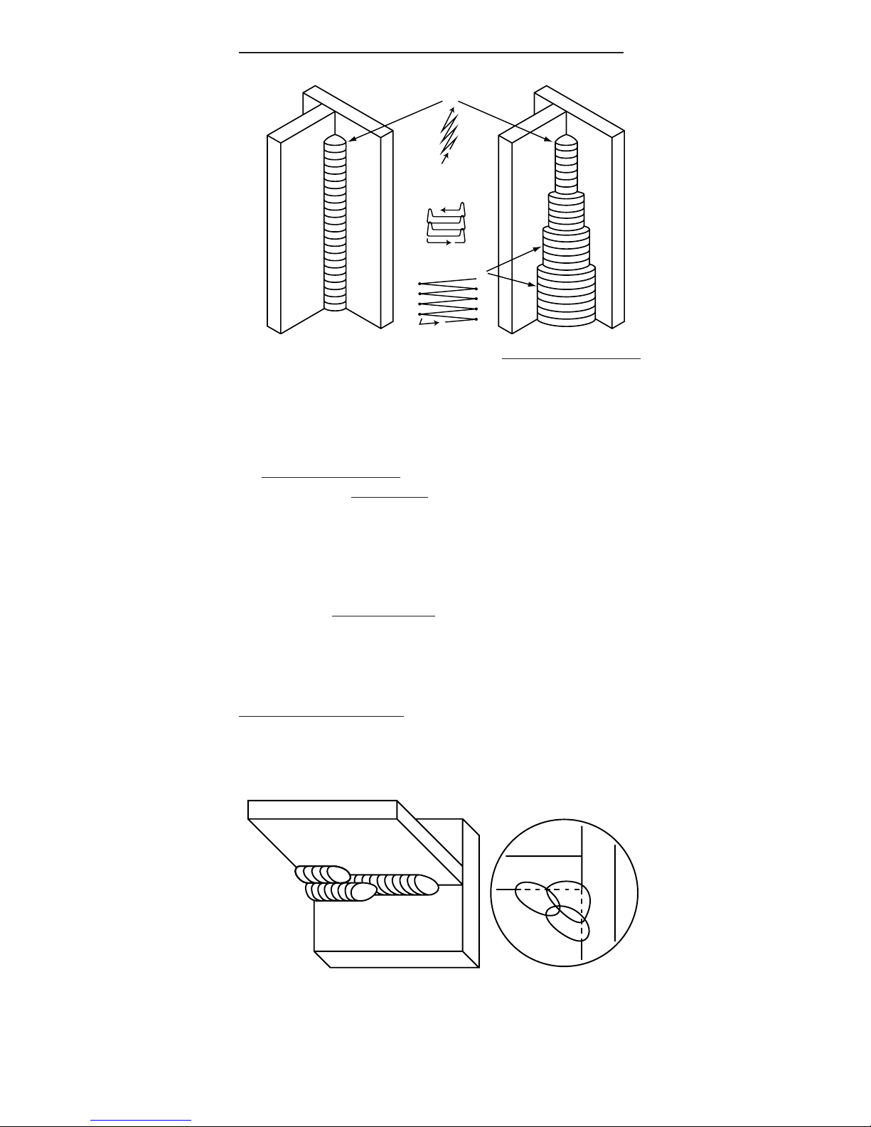
Vertical Up Techniques for Fillet and Groove Welds
1. Make first pass root beads with a whipping technique. Whip
the electrode tip out of the molten crater and up for a short
time to let the crater cool before returning the electrode tip to
the crater area to add more weld metal.
2. Root pass beads, particularly when made with a
whipping technique
, tend to be humped in the middle.
Therefore, a box weave
is often needed for the second pass
to assure good fusion along the edge of the first bead. The
box weave is similar to the straight weave except a slight
upward motion is made at both sides of the weld. Maintain a
short arc with no whipping.
3. Employ a straight weave
for the final passes. Simply move
the electrode tip back and forth across the surface of the
weld pausing slightly at both edges to insure penetration and
wash-in without undercut.
Overhead Techniques
Weld overhead as a series of root beads using a slight
circulation motion in the crater sometimes accompanied by a
whip. Weave beads are too fluid and will spill
.
Whip
first pass
Box weave
second pass
Straight weave
1
1
2
2
3
3
Page 6
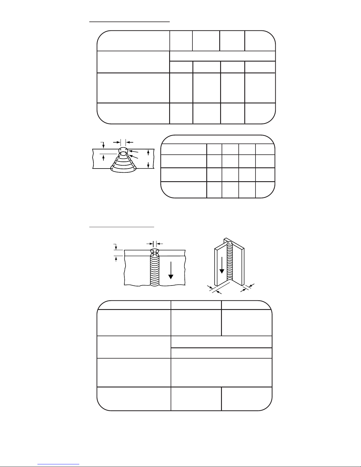
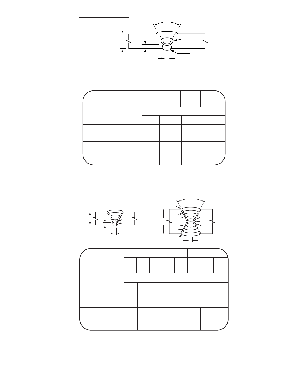
Vertical Up Groove Welds
Vertical Down Welds
Weld thicker plate with vertical up techniques.
-6-
Groove Fillet
Plate Size – T (in.) 3/16 —
Leg Size – L (in.)
—
5/32
No. of Passes 1-2 1
Electrode/AWS Class Fleetweld 5P, Fleetweld 5P+ E6010
Diameter (in.) 5/32
Current (Amps) 120
Polarity DC+
Arc Speed In./Min.
(1)
10-11
Ft. of Weld/Hr.
(2)
26 55
Lbs. of Elec./Ft. of Weld .168 .071
Table A
Plate Thickness-T
1/2” 5/8” 3/4” 1”
No. of Passes 3 4 6 10
Ft. of Weld/Hr.
(2)
6.6 4.4 3.1 1.8
Lbs. of Elec/Ft. .990 1.48 2.08 3.56
1/8"
1
2
1/8"
T
1/2” and thicker plates are more economically welded
with low hydrogen electrodes.
Plate Size – T (in.) 1/4 5/16 3/8 1/2-1
No. of Passes 1-2 1-2 1-2 All
Electrode/AWS Class Fleetweld 5P, Fleetweld 5P+ /E6010
Diameter (in.) 5/32 5/32 3/16 3/16
Current (Amps) 110 120 150 160
Polarity DC+ DC+ DC+ DC+
Arc Speed In./Min.
(1)
5-1/2 4 5 4
Ft. of Weld/Hr.
(2)
11 8.5 10 See
Lbs. of Elec./Ft. of Weld .323 .440 .586 Table A
3/32" gap
L
T
3/16"
(1) First pass only. On later passes adjust arc speed to obtain proper bead size.
(2) Total for all passes. 100% operating factor.
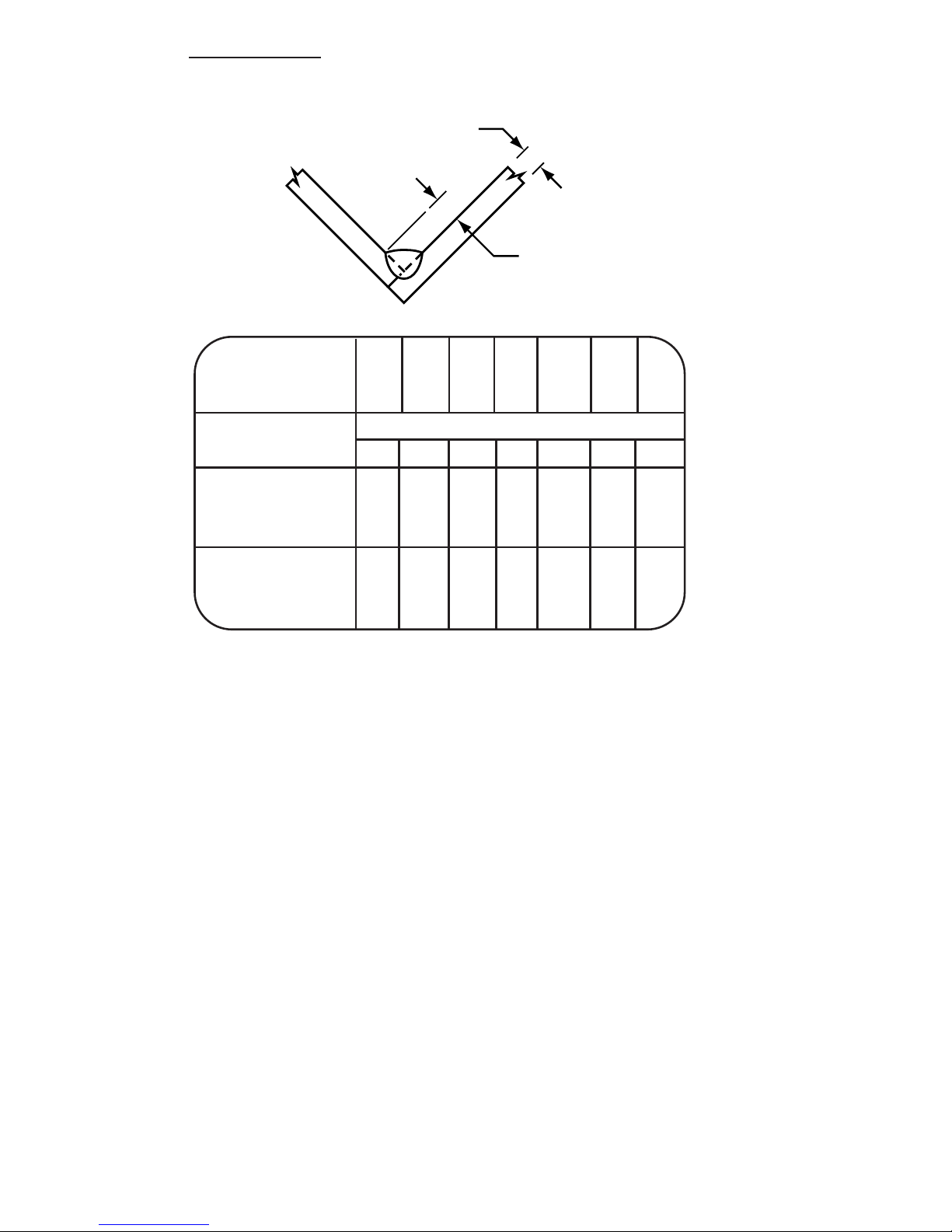
Page 7
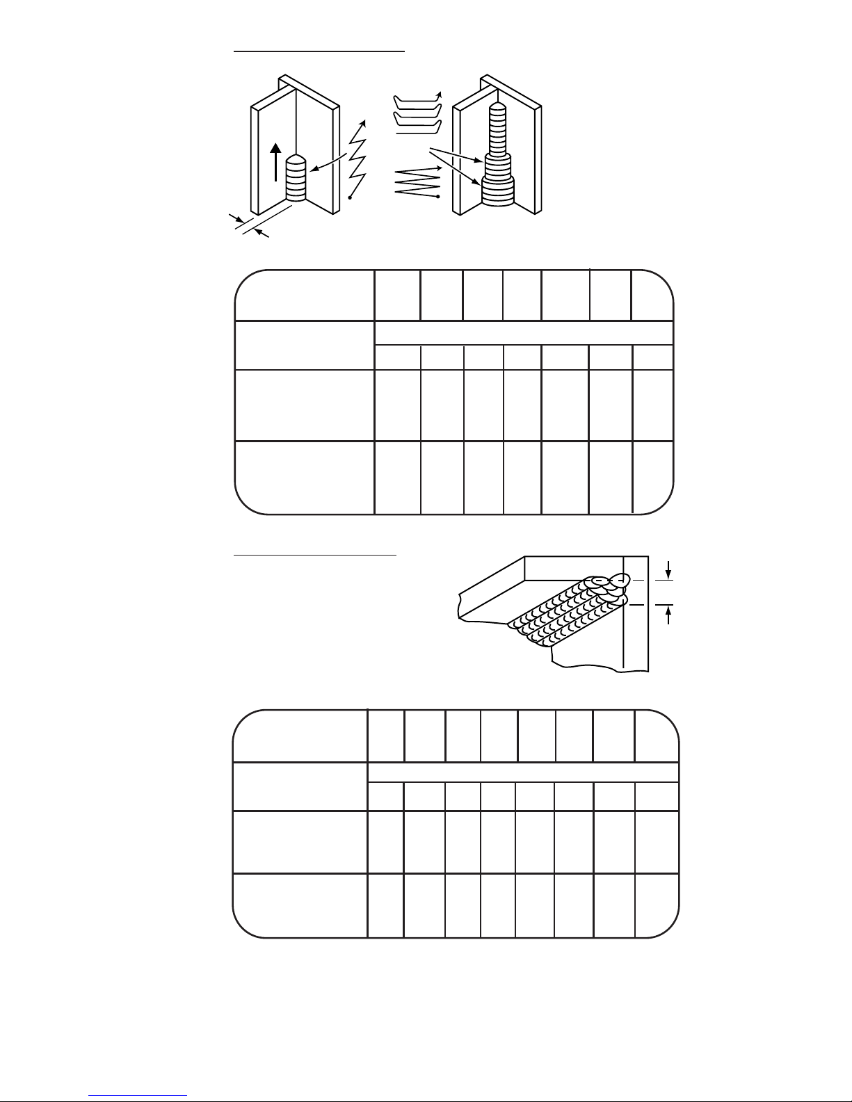
No. of Passes 1 1 1 1 1-2 1-3 1-4
Leg Size – L (in.) 3/16 1/4 5/16 3/8 1/2 5/8 3/4
Electrode/AWS Class Fleetweld 5P, Fleetweld 5P+
(1)
/ E6010
Diameter (in.) 3/16 3/16 3/16 3/16 3/16 3/16 3/16
Current (Amps) 150 155 155 155 160 160 160
Polarity DC+ DC+ DC+ DC+ DC+ DC+ DC+
Arc Speed In./Min.
(2)
85324-1/2 4-1/2 4-1/2
Ft. of Weld/Hr.
(3)
40 25 15 10 6.8 4.4 3.0
Lbs. of Elec./Ft. of .137 .211 .346 .514 .850 1.31 1.93
Weld
-7-
V
ertical Up Fillet Welds
Overhead Fillet Welds
After first bead, the sequence
of bead placements starts on
vertical plate for each layer.
No. of Passes 1 1 1 1-2 1-3 1-6 1-10 1-15
Leg Size – L 5/32 3/16 1/4 5/16 3/8 1/2 5/8 3/4
Electrode/AWS Class Fleetweld 5P, Fleetweld 5P+ /E6010
Diameter
(in.)
5/32 5/32 5/32 5/32 3/16 3/16 3/16 3/16
Current (Amps) 130 170 170 170 170 170 170 170
Polarity DC+ DC+ DC+ DC+ DC+ DC+ DC+ DC+
Arc Speed In./Min.
(2)
7-1/2 9 5 7 7 7 7 7
Ft. of Weld/Hr.
(3)
38 45 25 18 12 6.9 4.4 3.1
Lbs. of Elec./Ft. of .100 .145 .253 .369 .532 .945 1.48 2.13
Weld
or
L
L
(1) 5/32” electrode can be used to allow better control.
(2) First pass only. On later passes adjust arc speed to obtain proper bead size.
(3) Total for all passes. 100% operating factor.
Page 8

-8-
High-Deposition Welding
High deposition applications includes groove, fillet, lap and
corner welds in 3/16” and thicker plate welded with the work
level or slightly downhill. These joints are capable of holding a
large molten pool of weld metal as it freezes.
These welds are made with Jetweld electrodes because the high
iron powder content in the coating produces high deposit rates
to fill joints in the shortest time for economical welding.
Pr
ocedures
Lap welds . . . . . . . . . . . . . . . . . . . . . . . . . . . page 11
Corner Welds . . . . . . . . . . . . . . . . . . . . . . . . . page 11
Groove Welds . . . . . . . . . . . . . . . . . . . . . . . . page 12
Flat Fillet Welds . . . . . . . . . . . . . . . . . . . . . . . page 14
Horizontal Fillet Welds . . . . . . . . . . . . . . . . . . page 15
Alter
nate Electrodes
When desired, the following alternate electrodes can be used
with similar procedures:
Recommended
Alternate
Jetweld 1 (E7024-1) Jetweld 3 (E7024)
Jetweld 1 or 3 (E7024) Jetweld LH-3800 (E7028H8)
Jetweld Operating T
echniques
Polarity and Current – Use AC for fast welding speeds, high
deposit rates, and good arc characteristics. DC can be used but
the resulting arc blow may complicate control of the molten
puddle.
Optimum current for most jobs is 5-10 amps above the center of
the electrodes range. Do not exceed the center of the range for
x-ray quality deposits.
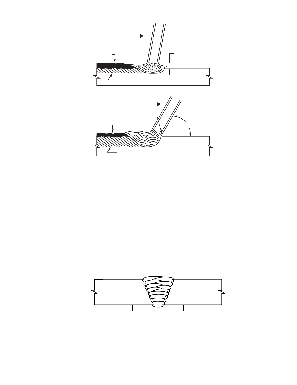
Use a Drag Technique – Tip the electrode 10 to 30° in the direction of travel and make stringer beads. Weld with the electrode
end lightly dragging on the work to force the molten metal out
from under the electrode tip allowing adequate penetration. The
smooth welds look almost like automatic welds.
Page 9
-9-
Travel fast, but not too fast for good slag coverage. Stay about
1/4” to 3/8” ahead of the molten slag. If travel speed is too slow,
a small ball of molten slag may form and roll ahead of the arc
causing erratic bead shape, spatter, and poor penetration.
Deep Groove Groove Welds – To hold the large pool of molten
weld metal from Jetweld electrodes, either a weld backing plate
or a root pass made with deep penetrating electrode (usually
E6010 or E6011) is required. Deposit Jetweld beads with a
stringer technique or a slight weave to obtain fusion to both
plates. Split weave welds are better than a wide weave near the
top of deep grooves. Size the second to last layer so the last
layer will not exceed a 1/16” buildup.
1/8" root gap between
electrode coating and plate
Slow travel
Fused metal
Plate
WRONG
Fast Travel
Fused metal
Electrode coating
touches plate lightly
Plate
RIGHT
60 to 80°
Slag
Slag
Page 10
-10-
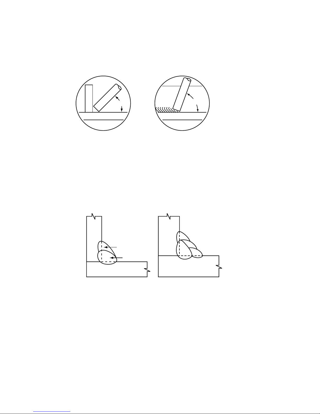
Fillet and Lap Welds – The ideal fillet or lap weld has equal legs
and a flat or slightly convex bead. Excess convexity wastes weld
metal. A concave bead is susceptible to shrinkage cracks.
Flat fillet and lap welds are made with the same general
techniques as groove welds.
Weld single pass fillets using a drag technique with the tip of the
electrode touching both plates. Usually weld with the electrode
at a 45° angle (end view) from the horizontal plate. However,
adjust this angle from as little as 30° to as much as 60° when
required to maintain equal leg sizes on both plates.
When two passes are needed, deposit the first bead mostly on
the bottom plate. To weld the second pass hold the electrode at
about 45° angle fusing into the vertical plate and the first bead.
Make multiple pass horizontal fillets as shown in the sketch. Put
the first bead in the corner with fairly high current even though
there may be slight undercut, succeeding passes will burn it out.
Deposit the second bead on the horizontal plate fusing into the
first bead. Hold the electrode angle needed to deposit the filter
beads as shown, putting the final bead against the vertical plate.
End view Side view
45°
60°
1
1
2
2
3
4
Page 11
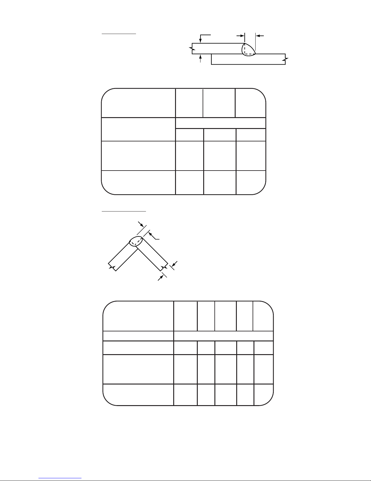
Lap Welds
Use fillet weld procedures
for laps on 3/8” and
thicker plate.
Cor
ner Welds
-11-
Plate Size – T (in.) 3/16 1/4 5/16 3/8 1/2
Leg Size – L (in.) 3/32 1/8 5/132 3/16 1/4
Pass 1 1 1 1 1
Electrode/Class Jetweld 1/E7024-1
Size 5/32 3/16 7/32 7/32 1/4
Current – Amps 215 260 330 340 390
Polarity AC AC AC AC AC
Arc Speed In./Min. 24.5 21 20.5 18 15.5
Ft. of Weld/Hr.
(1)
120 105 103 90 77
Lbs. of Elec./Ft. of weld .075 .114 .152 .175 .250
L
T
Plate Size – T (in.) 3/16 1/4 5/16
Leg Size – L (in.) 3/16 1/4 5/16
No. of Passes 1 1 1
Electrode/AWS Class Jetweld 1/E7024-1
Diameter (in.) 3/16 7/32 7/32
Current (Amps) 290 360 360
Polarity AC AC AC
Arc Speed In./Min. 15-1/2 15 13
Ft. of Weld/Hr.
(1)
78 75 65
Lbs. of Elec./Ft. of weld .170 .211 .253
L = 1/2 T
L
T
Note: Maximum strength, full size corner welds, as illustrated,
can be made using the next smaller E7024 electrode, lower
currents, slower arc speed and slower travel speed. Use 2
passes on 1/2” plate when making full size corner weld.
(1) 100% operating factor.
Page 12
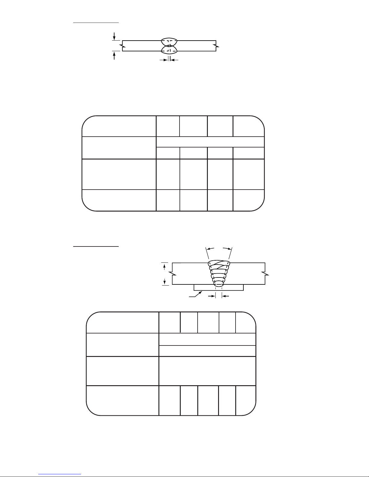
Groove Welds
Do not use for code quality work
This square edge groove joint requires the deep penetration of
Fleetweld 5P or 5P+.
Gr
oove Welds
First Pass
3/16” Jetweld 2 E6027
300 amps. AC at 14”/Min.
-12-
1/16" ± 1/32"
T
Plate Size – T (in.) 3/16 1/4 5/16 3/8
No. of Passes 2 2 2 2
Electrode/AWS Class Fleetweld 5P, Fleetweld 5P+/E6010
Diameter (in.) 1/4 5/16 5/16 5/16
Current (Amps) 240 325 390 410
Polarity DC+ DC+ DC+ DC+
Arc Speed In./Min.
(1)
18 18 18 18
Ft. of Weld/Hr.
(2)
45 45 45 45
Lbs. of Elec./Ft. of Weld .171 .275 .315 .330
(1) Both passes.
(2) Total for all passes. 100% operating factor.
30¡
5/16"Steel backup
T
Plate Size – T (in.) 5/16 3/8 1/2 3/4 1
No. of Fill Passes 2-3 2-3 2-4 2-6 2-8
Electrode /AWS Class Jetweld 2/E6027
Diameter (in.) 1/4
Current (Amps) 390
Polarity AC
Arc Speed In./Min.
(1)
14
Ft. of Weld/Hr.
(2)
20 22 17 11 8.2
Lbs. of Elec./Ft. of weld
(
3)
.524 .697 1.00 1.69 2.37
(1) First pass only. On later passes adjust arc speed to obtain proper
bead size.
(2) Total for all passes. 100% operating factor.
(3) Plus .228 lbs. of 3/16” E6027/ft. of weld for first pass.
Page 13
-13-
Deep Groove Welds
Joint A
Pass 1
E6011
Root passes - Joints A, B & C - 3/16 Fleetweld 35 (E6011), 175-180
Amps. AC at 6-9 in/min.
Over E6011 Root Passes
JOINT B JOINT C
Plate Size – T (in.) 5/16 3/8 1/2 3/4 1 3/4 1 1-1/2
No. of Passes 2 2-3 3 3-6 3-10 4-5 4-7 4-9
Electrode/AWS Class Jetweld 2/E6027
Diameter
(in.) 5/32 5/32 1/4 1/4 1/4 1/4
Current (Amps) 220 220 390 390 390 390
Polarity AC AC AC AC AC AC
Ft. of Weld/Hr.
(1)
21 16 14 8.2 5.3 9.0 6.2 4.1
Lbs. of Elec./Ft. of .142 .284 .354 1.47 2.94 .728 1.45 3.04
Weld
(2)
60°
1/8"
1/8"
Joint B
5/16" & 3/8" Pass 1 — E6011
1/2" - 1" Pass 1 & 2 — E6011
Joint C
Passes 1 to 3 —
E6011
T
2
1
1/8" Root
opening
T
9
8
7
4
5
6
2
1
3
(1) Total for all passes. 100% operating factor.
(2) Plus .160 lbs. of 3/16” E6011/ft. of weld for each root pass.
60°
1/16"
1/8"
Back gouge before
welding final pass
T
1
2
Plate Size – T (in.) 3/8 1/2 5/8 5/8
No. of Passes 2-3 2-3 2-3 4
Electrode/AWS Class Jetweld 2/E6027
Diameter (in.) 3/16 7/32 1/4 7/32
Current (Amps) 280 340 375 340
Polarity AC AC AC AC
Ft. of Weld/Hr.
(1)
21 19 14 14
Lbs. of Elec./Ft. of Weld
(2)
.366 .4810 .795 .235
JOINT A
(1) Total for all passes. 100% operating factor.
(2) Plus .160 lbs. of 3/16” E6011/ft. of weld for each root pass.
Page 14
-14-
Flat Fillet Welds
Also see Low Hydrogen Procedures.
For X-ray quality:
1. Use low hydrogen procedures, pages 24-34.
(or)
2. Weld 3/16” to 5/16” fillets with E6027 electrodes at the E7024
procedures. Weld 3/8” and larger fillets with 1/4” E6027 at
about 400 amps. Travel speed will be slower.
T
L
Plate Size – T 14 ga 12 ga 10 ga 3/16" 3/16" 1/4" 1/4"
No. of Passes 1 1 1 1 1 1 1
Leg Size – L (in.) — — — 5/32 5/32 3/16 3/16
Electrode/AWS Class Jetweld 1/E7024-1
Diameter (in.) 3/32 1/8 1/8 1/8 5/32 5/32 3/16
Current (Amps) 95 150 160 180 210 230 270
Polarity AC AC AC AC AC AC AC
Arc Speed In./Min.
(1)
15 17-1/2 17-1/2 17 16-1/2 17 14-1/2
Ft. of Weld/Hr.
(2)
75 88 88 85 83 85 72
Lbs. of Elec./Ft. of .049 .076 .082 .117 .162 .20 .29
Weld
(1) First pass only. On later passes adjust arc speed to obtain proper
bead size.
(2) Total for all passes. 100% operating factor.
Page 15

-15-
Horizontal Fillet W
elds
Also see Low Hydrogen Procedures.
Plate Size – T 14 ga 12 ga 10 ga 3/16 1/4 5/16 3/8 1/2 5/8 3/4 3/4 1
No. of Passes 1 2-3 1 2-3 1 2-4 1 2-5 1-2 1-3 1-4 1-5
Leg Size – L (in.) —— —5/32 3/16 1/4 5/16 3/8 1/2 9/16 5/8 3/4
Electrode/ AWSClass Jetweld 1/E7024-1
Diameter
(in.) 3/32 1/8 1/8 5/32 3/16 7/32 1/4 1/4 1/4 1/4 1/4 1/4
Current (Amps) 95 150 160 210 270 325 375 375 375 375 375 375
Polarity AC AC AC AC AC AC AC AC AC AC AC AC
Arc Speed In./Min.
(1)
15 17.5 17.5 17 16 17 13.5 11 11 11 11 11
Ft. of Weld/Hr.
(2)
75 88 88 85 80 85 68 55 28 22 17 12
Lbs. of Elec./Ft. of .050 .077 .083 .119 .166 .21 .30 .41 .73 .92 1.15 1.62
Weld
T
L
T
T
3
3
2
2
5
4
1
1
L
L
(1) First pass only. On later passes adjust arc speed to obtain proper bead size.
(2) Total for all passes. 100% operating factor.
For x-ray quality:
1. Use low hydrogen procedures, pages 24-34.
(or)
2. Weld 3/16” to 1/2” plate, use E6027 at slightly lower currents and arc speeds.
Page 16

-16-
Welding Inclined Plate
These procedures are used when:
1. The work cannot be positioned in the level position
for high speed welding with High Deposition
Jetweld electrodes.
2. The weld is made partly in the level position and
partly downhill.
Fleetweld 47 electrodes have a fairly high iron powder content in
the coating, which provides a good deposition rate consistent
with downhill welding ability.
Using a drag technique, maintain about a 5/32” distance
between the end of the electrode and the molten slag. If the
distance is too great, skips occur in the weld. If the distance is
too short, the slag will flow under the arc causing slag holes.
L
L
Page 17

-17-
Welding Inclined Plate
Downhill Angle (deg.) 0 60
(1)90(2)
030
(1)60(2)
010
(1)35(2)
010
(1)20(2)
0-5
(2)
No. of Passes 1 1 1 1 1
Leg Size – L
(in.) 5/32 1/4 1/4 5/16 3/8
Electrode/AWS Class Fleetweld 47 / E7014
Diameter (in.) 5/32 3/16 7/32 1/4 1/4
Current (Amps) 200 250 310 370 400
Polarity AC AC AC AC AC
Arc Speed In./Min.
(3)
13 13 16 12 12 13 11 11 13 9 9 11 7.5
Lbs. of Elec./Ft. of .095 .095 .081 .110 .110 .121 .191 .191 .180 .270 .270 .240 .390
(1) Maximum downhill angle for full size welds.
(2) Welds made at the maximum downhill angles listed for each electrode size tend
to be concave and undersized.
(3) 100% operating factor.
Page 18

-18-
High Speed Welding (Sheet Metal)
Welding sheet steel (18 through12 gauge) requires electrodes
that weld at high travel speeds with minimum skips, misses, slag
entrapment, and undercut.
Procedures
Groove welds . . . . . . . . . . . . . . . . . . . . . . . . . page 20
Edge Welds . . . . . . . . . . . . . . . . . . . . . . . . . . page 20
Fillet Welds . . . . . . . . . . . . . . . . . . . . . . . . . . page 21
Lap Welds . . . . . . . . . . . . . . . . . . . . . . . . . . . page 21
Corner Welds . . . . . . . . . . . . . . . . . . . . . . . . . page 22
Burnthrough Spot Welds . . . . . . . . . . . . . . . . page 23
Alter
nate Electrodes
When the recommended electrodes are not available, or if
preferred, the following electrodes can be substituted using
approximately the same procedures:
Electr
ode Class Alternate
Fleetweld 5P E6010 E6011
Fleetweld 5P+ E6010 E6011
Fleetweld 35 E6011 E6010
Fleetweld 7 E6012 E6013
Fleetweld 37 E6013 E7014
W
elding Techniques
Generally, use the highest current possible that will not burnthrough, undercut, or melt the edges of lap, corner, or edge
welds. Fast welding depends upon the operators skill at
staying on the joint and traveling at a uniform speed. A few
days practice may be needed by good welders when first
starting sheet metal welding.
For maximum welding speed, minimum distortion and flat welds
generally position joints for welding 45° to 75° downhill.
The procedure tables assume tight fit-up and adequate
clamping or tacking for fast travel speeds and minimum
distortion. Use copper backing whenever possible to decrease
burnthrough tendencies. When poor fit-up is encountered:
1. Reduce the current.
2. Increase the drag angle.
3. With E6010 or E6011 electrodes use a quick whip
technique with a slight circular motion in the crater to
bridge the gap.
4. With E6012 or E6013 electrodes, use a small quick
weave technique to bridge the gap.
Page 19

-19-
When welding with High Speed electrodes (E6012 and E6013)
deposit the entire weld in one pass using non-weave beads or a
slight weave. Drag the electrode on the joint and stay ahead of
the molten pool. Use enough drag angle so the arc force pushes
the weld metal back. Use currents in the high portion of the elec-
trode’s range.
When welding with Out-Of-Position electrodes (E6010 and
E6011), deposit the entire weld in one pass using non-weave
beads or a slight weave. Hold a 1/8” or shorter arc. Move as
fast as possible while maintaining good fusion. Use currents in
the middle of the electrode’s range.
Weld overhead joints using E6010 or E6011 electrodes with a
whip technique and a slight circular motion in the crater. Do not
weave. Point the electrode directly into the joint and slightly for-
ward into the direction of travel. Use a fairly short arc and travel
fast enough to avoid spilling. Use currents in the lower portion
of the electrode’s range. Overhead welding of 18 gauge and
thinner is not recommended.
Page 20

-20-
Plate Size 18ga 16ga 14ga 12ga 10ga
Electrode/AWS Class Fleetweld 5P, Fleetweld 5P+ /E6010
Diameter (in.) 3/32 1/8 1/8 5/32 3/16
Position
(1)
0-30° Downhill
Current (Amps) 40 70 80 120 135
Polarity
(2)
DC- DC- DC+ DC+ DC+
Arc Speed - In./Min.
(3)
24 32 28 22 19
Lbs of Elec./Ft. of Weld .024 .029 .026 .049 .070
Position
(1)
30-90° Downhill
Current (Amps) 45 75 90 130 150
Polarity
(
2)
DC- DC- DC+ DC+ DC+
Arc Speed In./Min.
(3)
28 36 30 25 20
Lbs. of Elec./Ft. of Weld .023 .028 .027 .048 .073
Groove Welds
Edge Welds
Flat Vertical (welded down)
Flat
Vertical (welded down)
(1) 45 to 75° downhill position recommended for easy operation and fast speeds.
(2) AC can be used – see page 22.
(3) For ft. of weld/hr. multiply in./min. by 5. 100% operating factor.
Plate Size 18ga 16ga 14ga 12ga 10ga
Electrode/AWS Class Fleetweld 5P, Fleetweld 5P+ /E6010
Diameter (in.) 3/32 1/8 1/8 5/32 3/16
Position
(1)
0-30° Downhill
Current (Amps) 50 80 85 115 140
Polarity
(
2)
DC- DC- DC- DC- DC-
Arc Speed - In./Min.
(3)
48 46 43 43 40
Lbs of Elec./Ft. of Weld .015 .023 .026 .038 .048
Position
(1)
30-90° Downhill
Current - Amps 55 90 95 125 155
Polarity
(2)
DC- DC- DC- DC- DC-
Arc Speed In./Min.
(3)
56 53 50 50 46
Lbs. of Elec./Ft. of Weld .014 .023 .025 .036 .047
Page 21

-21-
Fillet Welds
Also see High Deposition Procedures on page 28 for
14 to 10 gauge fillet welds with Jetweld electrodes.
Lap W
elds
Flat Horizontal Vertical (welded down)
Plate Size 18ga 16ga 14ga 12ga 10ga
Electrode/AWS Class Fleetweld 37/ E6013
Diameter (in.) 3/32 1/8 5/32 5/32 3/16
Position
(1)
0-30° Downhill
(5)
Current (Amps) 70 105 155 160 210
Polarity
(2)
AC AC AC AC AC
Arc Speed - In./Min.
(3) (4)
15 16 17 16 16
Lbs of Elec./Ft. of Weld .045 .053 .071 .079 .110
Position
(1)
30-90° Downhill
Current (Amps) 75 115 165 170 225
Polarity
(2)
AC AC AC AC AC
Arc Speed In./Min.
(3) (4)
16 19 21 20 18
Lbs. of Elec./Ft. of Weld .042 .049 .062 .070 .100
Flat Vertical (welded down)
Plate Size 18ga 16ga 14ga 12ga 10ga
Electrode/AWS Class Fleetweld 37/ E6013
Diameter (in.) 3/32 1/8 1/8 5/32 5/32
Position
(1)
0-30° Downhill
Current (Amps) 75 115 120 165 170
Polarity
(2)
AC AC AC AC AC
Arc Speed - In./Min.
(3) (4)
17 18 16 16 12
Lbs of Elec./Ft. of Weld .042 .055 .075 .085 .110
Position
(1)
30-90° Downhill
Current (Amps) 85 125 130 185 180
Polarity
(2)
AC AC AC AC AC
Arc Speed In./Min.
(3) (4)
21 22 21 21 14
Lbs. of Elec./Ft. of Weld .038 .050 .061 .069 .100
(4) Faster arc speeds can be obtained with Fleetweld 7 using DC- polarity and
these currents.
Page 22

Corner Welds
-22-
Weld Type/
Position 18ga 16ga 14ga 12ga 10ga
Fillet Welds
0-30º 15 16 17 16 16
30-90º 18 19 21 20 18
Lap Welds
0-30º 17 18 18 16 15
30-60º 21 22 23 21 18
Groove Welds
0-30º 22 30 29 27 25
30-60º 26 32 30 29 27
Edge Welds - Same as DC
Corner Welds - Same as DC
Flat
Vertical
(welded down)
18 to
10 gauge
Permissible for
18 & 16 gauge
1/2 T
T
Plate Size 18ga 16ga 14ga 12ga 10ga
Electrode/AWS Class Fleetweld 5P, Fleetweld 5P+ /E6010
Diameter (in.) 3/32 1/8 1/8 5/32 3/16
Position
(1)
0-30° Downhill
Current (Amps) 45 80 85 110 155
Polarity
(2)
DC- DC- DC- DC- DC+
Arc Speed - In./Min.
(3)
33 38 38 36 30
Lbs of Elec./Ft. of Weld .020 .028 .030 .043 .051
Position
(1)
30-90° Downhill
Current (Amps) 50 90 95 120 170
Polarity
(2)
DC- DC- DC- DC- DC+
Arc Speed In./Min.
(3)
38 43 43 40 36
Lbs. of Elec./Ft. of Weld .018 .028 .029 .044 .046
(1) 45 to 75º downhill position is recommended for easy welding and fast
speeds. Corner welds on 10 gauge steel can be welded 5-7 in./min. faster
when positioned 75 to 90º downhill rather than 45 to 75º downhill.
(2) For AC welding use:
a. E6011 in place of E6010 or E6013 in place of E6012
b. The same electrode diameters.
c. About 10% higher current.
d. The following arc speeds:
(3) For ft. of weld/hr. multiply in./min. by 5. 100% operating factor.
Arc Speed (inch/min)
Page 23

-23-
Burnthrough Spot Welds (Roof Decking to Beam)
Roof Deck Thickness 22 ga 20 ga 18 ga 16 ga
Electrode/AWS Class Fleetweld 22 /E6022
Diameter (in.) 1/8 1/8 5/32 1/8 5/32 5/32
Position Flat
Current (Amps) 110 120 150 150 165 180
Polarity DC- DC- DC- DC- DC- DC-
&AC &AC & AC & AC & AC & AC
Roof Deck
Roof Beam Flange
Page 24

-24-
Low Hydrogen Welding
Low hydrogen electrodes are recommended for three broad
areas of application:
1. On low alloy, high carbon, high sulfur, or other steels where
cracking is a problem.
2. When specified by governing codes.
3. For lowest costs on vertical, overhead and horizontal groove
welds on heavy (over 1/2”) plate.
Pr
ocedures
Vertical Up Groove Welds . . . . . . . . . . . . . . . page 27
Overhead Groove Welds . . . . . . . . . . . . . . . . page 27
Vertical Up Fillet Welds . . . . . . . . . . . . . . . . . . page 28
Overhead Fillet Welds . . . . . . . . . . . . . . . . . . page 28
Horizontal Groove Welds . . . . . . . . . . . . . . . . pages 29-30
Flat Fillet Welds . . . . . . . . . . . . . . . . . . . . . . . pages 31-32
Horizontal Fillet Welds . . . . . . . . . . . . . . . . . . pages 33-34
Recommended
Class
Jetweld LH-70 E7018
Jet-LH78 MR E7018
Excalibur
®
7018 E7018
Excalibur 7018-1 E7018-1
Jetweld LH-3800 (E7028) T
echniques
Employ the same techniques for this High-Deposition electrode
as recommended for E7024 electrodes. Clean the slag from
every bead on multiple pass welds to prevent slag inclusions
which would appear on X-ray inspection.
EXX18 W
elding Techniques
Procedures and techniques for E7018 electrodes can be used
for E8018, E9018, or E11018 Lincoln electrodes.
Polarity - Whenever possible use electrode positive for 5/32” and
smaller electrodes. AC can be used at about 10% higher currents.
Use AC on 3/16” and larger diameter electrodes to minimize arc
blow for best operating characteristics. DC+ can also be used
at about 10% lower currents.
Page 25

-25-
Drag the electrode lightly. Since low hydrogen electrodes rely on
the molten slag for shielding, never hold a long arc, whip, leave
the crater, or move rapidly in any direction. Failure to follow
these techniques may result in porosity and/or reduce mechanical properties.
For Clean Tie-Ins – Strike the arc ahead of the crater, move
quickly back into the crater, then proceed in the direction of
welding. This technique welds over the striking area, eliminating
porosity or tendency for poor starting bead shape.
Multiple Pass Welds – Clean the slag after each bead. When
welding in the downhand position, use stringer beads or small
weaves rather than wide weaves to avoid slag inclusions.
V
ertical Techniques
Use 5/32” or smaller electrodes and currents in the lower portion
of the electrode’s range. Techniques are as follows:
1. Use a triangular weave for heavy single pass welds.
Heavy Single Pass
Multipass
Straight weave
Stringer bead
Triangular weave
Page 26

-26-
2. For multipass welds, deposit a first pass bead using a slight
weave. We emphasize the importance of moving into the
corner to assure penetration into the corner. Weld additional
layers with a side-to-side weave hesitating at the sides long
enough to melt out any small slag pockets and minimize
undercut. Travel slow enough to maintain the shelf without
spilling weld metal.
3. With this technique, slag spills down the weld. As long as no
metal spills, operation is normal. Once welders are familiar
with the EXX18 techniques, they will quickly learn to make
sound welds of excellent appearance.
Horizontal Gr
oove and Overhead Weld Techniques
Weld with a series of first pass beads using a slight circular
motion in the crater. Do not whip. Use 5/32” or smaller
electrodes and currents in the lower portion of the
electrode’s range.
1
1
2
2
3
3
Page 27

Vertical Up Groove Welds
Also see Out-of-Position Procedures, page 4.
Overhead Gr
oove Welds
-27-
1/8"
First Pass
3/16" Fleetweld 5P
(E6010), 150 amps
DC+, 4-1/2 in./min.
1/8"
Last Pass - back gouge
before welding.
T
T
60°
Plate Size – T (in.) 1/2 5/8 3/4 1 1-1/4
No. of Passes 3 4 5 7 9
Electrode/AWS Class
Jet LH-78MR, Excalibur 7018/E7018
Excalibur 7018-1/E7018-1
Diameter (in.) 5/32
Current (Amps) 155
Polarity DC+
Arc Speed In./Min.
(1)
3-1/2
Ft. of Weld/Hr.
(2)
5.4 3.7 2.7 1.6 1.0
Lbs. of Elec./Ft. of weld .750
(3)
1.21
(3)
1.78
(3)
3.20
(3)
5.05
(3)
First Pass
1/8" Fleetweld 5P (E6010)
110 Amps DC +, 4-1/2 in./min.
Use split weave
for all passes
after third.
1/16"
1/16"
T
60°
Plate Size – T (in.) 5/16 3/8 1/2 3/4 1
No. of Passes 1 1 1 1 1
Electrode/AWS Class Jet LH-78MR,
Excalibur 7018 /E7018
Excalibur 7018-1 /E7018-1
Diameter 5/32”
Current (Amps) 160 160 160 160 160
Polarity DC+ DC+ DC+ DC+ DC+
Arc Speed In./Min.
(1)
3-1/2 3-1/2 3-1/2 4 4
Ft. of Weld/Hr.
(2)
10 7.5 5.0 2.5 1.5
Lbs. of Elec./Ft. of weld .330
(4)
.450
(4)
.840
(
(4)
1.88
(4)
3.34
(4)
(1) First low hydrogen pass only. On later passes adjust Arc Speed to obtain
proper bead size.
(2) Total for all passes. 100% operating factor.
(3) Plus .280 lbs. of 3/16” E6010/ft. of weld for first pass.
(4) Plus .160 lbs. of 1/8” E6010/ft. of weld for first pass.
Page 28

-28-
Vertical Up Fillet Welds
Overhead Fillet Welds
Also see Out-of Position Procedures, page 4.
No. of Pass 1 1 1 1 1 2 3
Leg Size – L (in.) 3/16 1/4 5/16 3/8 1/2 5/8 3/4
Electrode/AWS Class Jet LH-78MR,
Excalibur 7018 /E7018
Excalibur 7018-1 /E7018-1
Diameter (in.) 3/32 1/8 1/8 5/32 5/32 5/32 5/32
Current (Amps) 80 130 130 155 155 155 155
Polarity DC+ DC+ DC+ DC+ DC+ DC+ DC+
Arc Speed In./Min.
(1)
442.5 2 1.5 2.25 2.25
Ft. of Weld/Hr.
(2)
19 20 13 11 6.8 4.5 3.1
Lbs. of Elec./Ft. of .13 .22 .33 .47 .79 1.18 1.71
Weld
L
L
After first bead, the sequence
of bead placement starts on
vertical plate for each layer.
1/16" max.
root opening
No. of Passes 1 1 3 4 6 10 15
Leg Size – L (in.) 3/16 1/4 5/16 3/8 1/2 5/8 3/4
Electrode/AWS Class Jet LH-78MR,
Excalibur 7018 /E7018
Excalibur 7018-1 /E7018-1
Diameter (in.) 1/8 5/32 5/32 5/32 5/32 5/32 5/32
Current (Amps) 130 130 160 160 160 160 160
Polarity DC+ DC+ DC+ DC+ DC+ DC+ DC+
Arc Speed In./Min.
(1)
6.5 3.5 8.5 9 7.5 7.5 8.5
Ft. of Weld/Hr
.
(2)
33 18 15 10 5.9 3.8 2.6
Lbs. of Elec./Ft. of .13 .24 .35 .51 .91 1.42 2.05
Weld
(1) First low hydrogen pass only. On later passes adjust arc speed to obtain
proper bead size.
(2) Total for all passes. 100% operating factor.
Page 29

-29-
Horizontal Groove Welds
Back gouge first bead as needed
1/8"
T
45°
15°
Plate Size – T (in.) 1 2
No. of Passes 1-2 3-12 1-20 21-38
Electrode/AWS Class Jet LH-78MR,
Excalibur 7018 /E7018
Excalibur 7018-1/E7018-1
Diameter
(in.)
3/16
Current (Amps) 230 200 230 200
Polarity DC+ DC+ DC+ DC+
Arc Speed In./Min.
(1)
9 8.5 9 8.5
Ft. of Weld/Hr.
(2)
2.5 .76
Lbs. of Elec./Ft. of Weld 2.81 9.49
1/4"
5/8"
T
45°
3/4"
Plate Size – T (in.) 5/8 3/4
No. of Passes 5 9 6 11
Electrode/AWS Class Jet LH-78MR,
Excalibur 7018 /E7018
Excalibur 7018-1 /E7018-1
Diameter
(in.)
3/16
Current (Amps) 230 200 230 200
Polarity DC+ DC+ DC+ DC+
Arc Speed In./Min.
(1)
9 8.5 9 8.5
Ft. of Weld/Hr.
(2)
3.2 2.5
Lbs. of Elec./Ft. of Weld 2.26 2.95
(1) Arc speed for first pass approximately 5 in./min.
(2) Total for all passes. 100% operating factor.
Page 30

-30-
Horizontal Groove Welds
Use steel backing (as on page 29).
T
T/2
45°
Plate Size – T (in.) 1-1/2 3
No. of Passes 4 9 12 22
Electrode/AWS Class Jet LH-78MR, Excalibur 7018 /E7018
Excalibur 7018-1 /E7018-1
Diameter
(in.)
3/16
Current (Amps) 230 200 230 200
Polarity DC+ DC+ DC+ DC+
Arc Speed In./Min.
(1)
9 8.5 9 8.5
Ft. of Weld/Hr.
(2)
3.6 1.2
Lbs. of Elec./Ft. of Weld 3.12 6.19
1" 1-1/4" 1-1/2"
Plate Size – T (in.) 1 1-1/4 1-1/2
No. of Passes 1-11 12-17 1-16 17-24 1-22 23-33
Electrode/AWS Class Jet LH-78MR, Excalibur 7018 /E7018
Excalibur 7018-1 /E7018-1
Diameter
(in.)
3/16
Current (Amps) 230 200 230 200 230 200
Polarity DC+ DC+ DC+ DC+ DC+ DC+
Arc Speed In./Min.
(1)
9 8.5 9 8.5 9 8.5
Ft. of Weld/Hr.
(2)
1.6 1.1 .85
Lbs. of Elec./Ft. of 4.58 6.56 8.83
Weld
(1) Arc speed for first pass approximately 5 in./min.
(2) Total for all passes. 100% operating factor.
Page 31

-31-
Flat Fillet Welds
Also see, High Deposition Procedures, page 8.
L
(1) First pass only. On later passes, adjust arc speed to obtain proper bead size.
(2) Total for all passes. 100% operating factor.
Note: E7028 can produce code quality welds. E7028 is recommended for making high speed low cost welds
using High-Deposition electrode (high iron powder) techniques described on pages 11-15.
No. of Passes 1 1 1 1 1 2 3 4
Leg Size – L
(in.) 5/32 3/16 1/4 5/16 3/8 1/2 5/8 3/4
Electrode/AWS Class Jetweld LH-3800/E7028
Diameter (in.) 5/32 3/16 3/16 7/32 1/4 1/4 1/4 1/4
Current (Amps) 200 260 280 330 400 400 400 400
Polarity AC AC AC AC AC AC AC AC
Arc Speed In./Min.
(1)
14 14 11-1/2 10-1/2 9 10-1/2 10 9
Ft. of Weld/Hr.
(2)
70 70 58 53 45 26 16 11
Lbs. of Elec./Ft. of .104 .147 .208 .285 .437 .776 1.24 1.78
Weld
With E7028 Electrode
4
5
L
2
1
3
Page 32

-32-
Flat Fillet Welds
Also see High Deposition Procedures, page 11.
(1) First pass only. On later passes, adjust arc speed to obtain proper bead size.
(2) Total for all passes. 100% operating factor.
Note: E7018 can produce code quality welds. E7018 procedures are used when E7028 is not available
and for electrodes E8018 and E11018.
No. of Passes 1 1 1 1 1 2 4 5
Leg Size – L
(in.) 5/32 3/16 1/4 5/16 3/8 1/2 5/8 3/4
Electrode/AWS Class Jet LH-78MR, Jetweld LH-70, Excalibur 7018, Excaliibur 7018-1
Diameter
(in.) 3/16 7/32 7/32 1/4 1/4 1/4 1/4 1/4
Current (Amps) 240 275 275 350 350 350 350 350
Polarity AC AC AC AC AC AC AC AC
Arc Speed In./Min.
(1)
14 13.5 9.5 7.5 6.5 7.5 7 7
Ft. of Weld/Hr.
(2)
70 68 48 38 33 17 12 8
Lbs. of Elec./Ft. of .109 .132 .195 .272 .409 .727 1.14 1.50
With E7018 Electrode
L
4
5
L
2
1
3
Page 33

-33-
Horizontal Fillet W
elds
(1) First pass only. On later passes, adjust arc speed to obtain proper bead size.
(2) Total for all passes. 100% operating factor.
Note: E7028 can produce code quality welds. E7028 is recommended for making high speed low cost welds
using High-Deposition electrode (high iron powder) techniques, described on pages 11-15.
No. of Passes 1 1 1 1 2 2 3 4
Leg Size – L (in.) 5/32 3/16 1/4 5/16 3/8 1/2 5/8 3/4
Electrode/AWS Class Jetweld LH-3800 /E7028
Diameter
(in.) 5/32 3/16 7/32 7/32 7/32 1/4 1/4 1/4
Current (Amps) 215 260 335 335 335 390 390 390
Polarity AC AC AC AC AC AC AC AC
Arc Speed In./Min.
(1)
13 12 12.5 10 12 9.5 9.5 8.5
Ft. of Weld/Hr.
(2)
65 60 63 50 30 24 15 11
Lbs. of Elec./Ft. of .112 .157 .236 .320 .483 .819 1.28 1.82
With E7028 Electrode
L
L
Page 34

-34-
Horizontal Fillet W
elds
(1) First pass only. On later passes, adjust arc speed to obtain proper bead size.
(2) Total for all passes. 100% operating factor.
Note: E7018 can produce code quality welds. E7018 procedures are used when E7028 is not available and for
electrodes E8018 and E11018.
No. of Passes 1 1 1 1 2 3 4 5
Leg Size – L
(in.) 5/32 3/16 1/4 5/16 3/8 1/2 5/8 3/4
Electrode/AWS Class Jet LH-78MR, Jetweld LH-70, Excalibur 7018, Excalibur 7018-1
Diameter
(in.) 3/16 7/32 7/32 1/4 1/4 1/4 1/4 1/4
Current (Amps) 240 275 275 350 350 350 350 350
Polarity AC AC AC AC AC AC AC AC
Arc Speed In./Min.
(1)
13 11.5 9 7 9 10 8 7.5
Ft. of Weld/Hr.
(2)
65 58 45 35 26 17 11 7.5
Lbs. of Elec./Ft. of .111 .140 .203 .335 .480 .785 1.18 1.62
With E7018 Electrode
L
L
Page 35

-35-
Minimum Preheat and Interpass Temperature
(1)
For stick electrode welding only
Based on AWS Specification D1.1
Definitions
T – Thickness of the thickest part at point of welding.
Col. 1 – For the following steels when welded with other than
low hydrogen electrodes ASTM A36; A53 Grade B;
A106 Grade B; A131 Grades A, B, CS, D, DS, E; A139
Grade B; A381 Grade Y35; A500 Grades A, B; A501;
A516; A524 Grades I & II; A570 All grades; A573 Grade
65; A709 Grade 36 (≤ 3/4 in. [20mm]); AP15L Grades
B, X42; ABS Grades A, B, C, D, CS, DS, E.
Col. 2 – For the following steels: All steels listed in Column 1,
and additionally: ASTM A36 (>3/4 in. [20mm]); A53
Grade B; A106 Grade B; A131 Grades A, B, CS, D, DS,
E, AH32 & 36, DH 32 & 36, EH 32 & 36; A139 Grade B;
A381 Grade Y35; A441; A500 Grade A, Grade B;
A501; A516 Grades 55 & 60, Grades 65 & 70, A524
Grades 1 & 2; A529 Grades 50 & 55; A537 Classes I & II;
A570 All Grades; A572 Grades 42, 50, 55; A573 Grade
60; A588, A595 Grades A, B, C; A606; A607 Grades
45, 50, 55; A618 Grades Ib, II, III; A633 Grades A, B,
Grades C, D; A709 Grades 36 (≤ 3/4 in. [20mm]), 50,
50W; A710 Grade A, Class 2 (≤ 2 in. [50mm]); A808;
A913 Grade 50; A992; API 5L Grade B, Grade X42; API
Spec. 2H Grades 42, 50; API 2W Grades 42, 50, 50T;
API 2Y Grades 42, 50, 50T; ABS Grades AH 32 & 36,
DH 32 & 36, EH 32 & 36; ABS Grades A, B, D, CS, DS,
Grade E
Col. 3 – For steels ASTM A572 Grades 60 and 65, A633 Grade
E; API 5L Grade X52; ASTM A913 Grades 60, 65; A710
Grade A, Class 2 (≤ 2 in. [50mm]); A710 Class 3 (≤ 2 in.
[50mm]); A709 Grade 70W; A852, API 2W Grade 60;
API 2Y Grade 60
Col. 4 – All thicknesses ≥ 1/8 in. [3mm]. ASTM A710 Grade A
(all classes); ASTM A913 Grades 50, 60, 65. SMAW
electrodes capable of depositing weld metal with a
maximum diffusible hydrogen content of 8 ml/100g
(H8), when tested according to AWS A4.3.
Low Hydrogen Electrodes
T
Inches Col 1. Col. 2 Col. 3 Col. 4
Thru 3/4” 32ºF
(2)
32ºF
(2)
50ºF 32ºF
(2)
3/4 thru 1-1/2 150ºF 50ºF 150ºF 32ºF
(2)
1-1/2 thru 2-1/2 225ºF 150ºF 225ºF 32ºF
(2)
Over 2-1/2” 300ºF 225ºF 300ºF 32ºF
(2)
Page 36

-36-
Stick Electrode Typical Operating Procedures
Sizes & Current Ranges (Amps)
Product AWS Electrode
Name Class Polarity 3 /3 2” 1/8” 5/32” 3/16” 7/32” 1/4”
Fleetweld®5P E6010 DC+ 40-70 75-130 90-175 140-225 200-275 220-325
Fleetweld 5P+ E6010 DC+ 40-70 65-130 90-175 140-225 --- ---
Fleetweld 35 E6011 AC 50-85 75-120 90-160 120-200 150-260 190-300
DC± 40-75 70-110 80-145 110-180 135-235 170-270
Fleetweld 180 E6011 AC 40-90 60-120 115-150 --- --- ---
DC± 40-80 55-110 105-135 --- --- ---
Fleetweld 22 E6022 DC+ --- 110-150 150-180 --- --- ---
For Welding High Tensile Pipe
Shield-Arc®85 E7010-A1 DC+ 50-90 75-130 90-175 140-225 --- ---
Shield-Arc HYP+ E7010-P1 DC+ --- 75-130 90-185 140-225 --- ---
Shield-Arc 70+ E8010-G DC+ --- 75-130 90-185 140-225 --- ---
Shield-Arc 80 E8010-G DC+ --- 75-130 90-185 140-225 160-250 ---
Shield-Arc 90 E9010-G DC+ --- 75-130 90-185 140-225 --- ---
“Out-of-Position” Group
All-purpose stick electrodes for general purpose fabrication and maintenance welding. Capable of x-ray quality welds out-of-position. Particularly good for vertical and
overhead. Deep penetration with maximum admixture. Light slag and flat beads
with distinctive ripples.
7018 H4R
OPTIONAL SUPPLEMENTAL
DESIGNATOR
AWS CLASS (OR NAME)
ON EACH ELECTRODE
LOOK FOR LINCOLN'S
SYMBOL OF DEPENDABILITY
Minimum Preheat and Interpass Temperature
(1)
Continued
For stick electrode welding only
Based on AWS Specification D1.1
Notes
(1) Welding shall not be done when ambient temp. is lower than 0ºF.
Parts on which metal is being deposited shall be at or above the
specified temperature for a distance equal to the thickness of the part
being welded, but not less than 3”, in all directions from the point of
welding. Preheat and interpass temperature must be sufficient to
prevent cracking. Temperature above the minimum may be
required for highly restrained welds. For ASTM A709 Grade 70W
and ASTM A852 Grade 70, the maximum preheat and interpass temperature shall not exceed 400ºF for thicknesses thru 1-1/2”, and
450ºF for greater thicknesses.
(2) When the base metal temperature is below 32ºF, preheat to at least
70ºF and maintain this minimum temperature during welding.
Page 37

-37-
Sizes & Current Ranges (Amps)
Electrodes are manufactured in those sizes for
which current ranges are given
Product AWS Electrode
Name Class Polarity
3/32” 1/8” 5/32” 3/16” 7/32” 1/4”
Fleetweld 7 E6012 DC- --- 80-135 110-180 155-250 225-295 245-325
AC --- 90-150 120-200 170-275 250-325 275-360
Fleetweld 37 E6013 AC 75-105
(1)
110-150 160-200 205-260 --- ---
DC± 70-95 100-135 145-180 190-235 --- ---
Fleetweld 47 E7014 AC 80-100 110-160 150-225 200-280 260-340 280-425
DC- 75-95 110-145 135-200 185-235 235-305 260-380
“High Speed” Group
Operates in all positions, but most widely use downhill, horizontal or in the flat position. Ideal for irregular or short welds that change direction or position. Medium
deposit rates and medium penetration. Appearance ranges from smooth and ripplefree to even with distinct ripples.
(1)
Range for 5/64” Fleetweld 37 is 50 - 80 amps AC or 45-75 amps DC. 1/16” Fleetweld 37 is
20-45 amps AC or DC.
Sizes & Current Ranges (Amps)
Electrodes are manufactured in those sizes
which current ranges are given
Product AWS Electrode
Name Class Polarity
1/8” 5/32” 3/16” 7/32” 1/4”
Jetweld®1 E7024-1 AC 115-175
(1)
180-240 240-300 300-380 340-440
DC± 100-160 160-215 220-280 270-340 320-400
Jetweld 3 E7024 AC 115-175
(1)
180-240 240-315 300-380 350-450
DC± 100-160 160-215 215-285 270-340 315-405
Jetweld 2 E6027 AC --- 190-240 250-300 300-380 350-450
DC± --- 175-215 230-270 270-340 315-405
“High Deposition” Group
Highest deposition rates of all electrodes. Flat, horizontal and slightly downhill
(15° maximum) position only. Easy slag removal and smooth, ripple-free beads
are flat or slightly convex with minimal spatter.
(1)
Range for 3/32” is 65-120 amps AC or 60-110 amps DC±.
Page 38

-38-
Sizes & Current Ranges (Amps)
Electrodes are manufactured in those sizes for
which current ranges are given
Product AWS Electrode
Name Class Polarity
3/32” 1/8” 5/32” 3/16” 7/32” 1/4” 5/16”
Excalibur 7018 E7018H4R DC+ 70-110 85-150 125-200 170-260 --- --- --Excalibur 7018-1 E7018-1H4R AC 80-120 95-160 130-210 180-280 --- ---
Jetweld
®
LH-70 E7018H4R DC+ 70-100 90-150 120-190 170-280 210-330 290-430 375-500
AC 80-120 110-170 135-225 200-300 260-380 325-440 400-530
Jetweld LH-73 E7018H8 AC 75-120 105-150 130-200 --- --- --- ---
DC+ 70-115 100-140 120-185 --- --- --- ---
Jet-LH
®
78 MR E7018H4R DC+ 85-110 110-160 130-200 180-270 250-330 300-400 ---
AC --- 120-170 140-230 210-290 270-370 325-420 ---
Jetweld LH-3800 E7028H8 AC --- --- 180-270 240-330 275-410 360-520 ---
DC+ --- --- 170-240 210-300 260-380 --- ---
Low Hydrogen Group
For welding carbon and low alloy steels that require 70,000 psi tensile strength
deposits. These low hydrogen electrodes can produce dense, x-ray quality welds
with notch toughness properties. The E7018 electrodes have “Fill-Freeze”
characteristics and the E7028 electrode has “Fast-Fill” characteristics.
Sizes & Current Ranges (Amps)
Electrodes are manufactured in those sizes for
which current ranges are given
Product AWS Electrode
Name Class Polarity
3/32” 1/8” 5/32” 3/16” 7/32” 1/4”
Excalibur 7018-A1 MR E7018-A1 H4R DC+ 70-110 90-160 130-210
--- --- ---
AC 80-120 100-160 140-210
--- --- ---
Jetweld LH-90 MR E8018-B2 DC+ --- 110-150 130-190 180-270 --- ---
AC --- 120-170 140-225 210-290 --- ---
Jet-LH 8018-B2 MR E8018-B2 DC+ 70-100 110-150 120-190 --- --- ---
AC 70-95 85-120 135-200 --- --- ---
Jet-LH8018-C1MR E8018-C1H4R DC+ --- 90-150 120-180 180-270 --- 250-350
AC --- 110-160 140-200 200-300 --- 300-400
Excalibur 8018-C1 MR E8018-C1H4R DC+ 70-110 90-160 130-210 180-300 250-330 300-400
AC 80-120 100-160 140-210 200-300 270-370 325-430
Jet-LH 8018-C3 MR E8018-C3H4R DC+ --- 110-150 130-190 180-270 250-330 300-400
AC --- 120-170 140-225 210-290 270-370 325-420
Excalibur 8018-C3 MR E8018-C3 H4R DC+ 70-110 90-160 130-210 180-300 250-330 300-400
AC 80-120 100-160 140-210 200-300 270-370 325-420
Jet-LH 9018-B3 MR E9018-B3 DC+ 70-100 100-140 120-190 --- --- ---
AC 85-120 110-150 135-200 --- --- ---
Excalibur 9018M MR E9018-M H4R DC+ 70-110 90-160 130-210 180-300
--- ---
Jetweld LH-110M MR E11018-MH4R DC+ 70-110 90-155 120-190 160-280 190-310 230-360
AC 80-110 100-170 135-225 200-310 240-350 290-410
Low Hydrogen, Low Alloy Steel Group
Made for welding low alloy steels that require specific mechanical or chemical
properties of one of these electrodes. Specifically for use in cryogenics, high
temperature applications, and for x-ray quality requirements. These electrodes have
Low Hydrogen “Fill-Freeze” operating characteristics similar to Jetweld LH-70.
Page 39

-39-
PROTECT YOURSELF AND OTHERS FROM POSSIBLE SERIOUS
INJURY OR DEATH. KEEP CHILDREN AWAY. PACEMAKER
WEARERS SHOULD CONSULT WITH THEIR DOCTOR BEFORE
OPERATING.
Read and understand the following safety highlights. For additional safety information it is strongly recommended that you purchase a copy of “Safety in
Welding & Cutting - ANSIStandard Z49.1” from the American Welding Society,
P.O. Box 351040, Miami, Florida 33135 or CSA Standard W117.2-1974. AFree
copy of “Arc Welding Safety” booklet E205 is available from the Lincoln Electric
Company, 22801 St. Clair Avenue, Cleveland, Ohio 44117-1199.
BE SURE THAT ALL INSTALLATION, OPERATION, MAINTENANCE,
AND REPAIR PROCEDURES ARE PERFORMED ONLY BY
QUALIFIED INDIVIDUALS.
WARNING
ARC WELDING can be hazardous.
NOTE1: Joining Electrodes, Non-Charpy V-Notch Rated
These electrodes (see below) and others of the same AWS
classification, are not required to deposit weld metal capable
of delivering any minimum specified Charpy V-Notch (CVN)
properties. It should not be used in applications where minimum specified CVN properties are required. Typical applications where minimum specified CVN properties are required
include, but are not restricted to, bridges, pressure vessels,
and buildings in seismic zones. The user of this product is
responsible for determining whether minimum CVN properties are required for the specific application.
Fleetweld 7
Fleetweld 22
Fleetweld 37
Fleetweld 47
Jetweld 3
NOTE 2: Joining Electrodes, Non-Low Hydrogen
These electrodes (see below) and others of the same
AWS classification, are not required to deposit weld
metal that is low in diffusible hydrogen. Therefore, these
electrodes should not be used in applications where the
hydrogen content of the weld metal is required to be
controlled, such as applications that involve steels with
higher carbon and alloy content, and higher strength.
Fleetweld 5P Shield-Arc 90
Fleetweld 5P+ Shield-Arc HYP+
Fleetweld 35 Fleetweld 47
Fleetweld 35LS Jetweld 1
Fleetweld 180 Jetweld 2
Fleetweld 7 Jetweld 3
Fleetweld 37 Shield-Arc 70+
Fleetweld 22 Shield-Arc 80
Shield-Arc 85
Page 40

-40-
ARC RAYS can burn.
2.a. Use a shield with the proper filter and cover plates to
protect your eyes from sparks and the rays of the arc
when welding or observing open arc welding. Headshield
and filter lens should conform to ANSI Z87. I standards.
2.b. Use suitable clothing made from durable flame-resistant material to
protect your skin and that of your helpers from the arc rays.
2.c. Protect other nearby personnel with suitable non-flammable screening
and/or warn them not to watch the arc nor expose themselves to the
arc rays or to hot spatter or metal.
ELECTRIC SHOCK can kill.
1.a. The electrode and work (or ground) circuits are electrically
“hot” when the welder is on. Do not touch these “hot” parts with
your bare skin or wet clothing. Wear dry, hole-free gloves to
insulate hands.
1.b. Insulate yourself from work and ground using dry insulation. Make certain the insulation is large enough to cover your
full area of physical contact with work and ground.
In addition to the normal safety precautions, if welding must be performed under electrically hazardous conditions (in damp locations or
while wearing wet clothing; on metal structures such as floors, gratings
or scaffolds; when in cramped positions such as sitting, kneeling or
lying, if there is a high risk of unavoidable or accidental contact with
the workpiece or ground) use the following equipment:
• Semiautomatic DC Constant Voltage (Wire) Welder.
• DC Manual (Stick) Welder.
• AC Welder with Reduced Voltage Control.
1.c. In semiautomatic or automatic wire welding, the electrode, electrode reel,
welding head, nozzle or semiautomatic welding gun are also electrically
“hot”.
1.d. Always be sure the work cable makes a good electrical connection with the
metal being welded. The connection should be as close as possible to the
area being welded.
1.e. Ground the work or metal to be welded to a good electrical (earth) ground.
1.f. Maintain the electrode holder, work clamp, welding cable and welding machine
in good, safe operating condition. Replace damaged insulation.
1.g. Never dip the electrode in water for cooling.
1.h. Never simultaneously touch electrically “hot” parts of electrode holders connected to two welders because voltage between the two can be the total of
the open circuit voltage of both welders.
1.i. When working above floor level, use a safety belt to protect yourself from a fall
should you get a shock.
1.j. Also see Items 4.c. and 6.
Page 41

-41-
FUMES AND GASES can be
dangerous.
3.a. Welding may produce fumes and gases hazardous to
health. Avoid breathing these fumes and gases.When
welding, keep your head out of the fume. Use enough
ventilation and/or exhaust at the arc to keep fumes and
gases away from the breathing zone. When welding with
electrodes which require special ventilation such as
stainless or hard facing (see instructions on container or MSDS) or
on lead or cadmium plated steel and other metals or coatings
which produce highly toxic fumes, keep exposure as low as possible and below Threshold Limit Values (TLV) using local exhaust or
mechanical ventilation. In confined spaces or in some circumstances, outdoors, a respirator may be required. Additional precautions are also required when welding on galvanized steel.
3.b. Do not weld in locations near chlorinated hydrocarbon vapors coming
from degreasing, cleaning or spraying operations. The heat and rays of
the arc can react with solvent vapors to form phosgene, a highly toxic
gas, and other irritating products.
3.c. Shielding gases used for arc welding can displace air and cause injury or
death. Always use enough ventilation, especially in confined areas, to
insure breathing air is safe.
3.d. Read and understand the manufacturer’s instructions for this equipment
and the consumables to be used, including the material safety data sheet
(MSDS) and follow your employer’s safety practices. MSDS forms are
available from your welding distributor or from the manufacturer.
3.e. Also see item 7b.
WELDING SPARKS
can cause
fire or explosion.
4.a..Remove fire hazards from the welding area. If this is
not possible, cover them to prevent the welding sparks
from starting a fire. Remember that welding sparks and hot
materials from welding can easily go through small cracks
and openings to adjacent areas. Avoid welding near
hydraulic lines. Have a fire extinguisher readily available.
4.b. Where compressed gases are to be used at the job site, special precautions
should be used to prevent hazardous situations. Refer to “Safety in Welding
and Cutting” (ANSI Standard Z49.1) and the operating information for the
equipment being used.
4.c. When not welding, make certain no part of the electrode circuit is touching
the work or ground. Accidental contact can cause overheating and create a
fire hazard.
4.d. Do not heat, cut or weld tanks, drums or containers until the proper steps
have been taken to insure that such procedures will not cause flammable or
toxic vapors from substances inside. They can cause an explosion even
though they have been “cleaned.” For information purchase “Recommended
Safe Practices for the Preparation for Welding and Cutting of Containers and
Piping That Have Held Hazardous Substances”, AWS F4.1 from the
American Welding Society (see address above).
4.e. Vent hollow castings or containers before heating, cutting or welding. They
may explode.
4.f. Sparks and spatter are thrown from the welding arc. Wear oil free protective
garments such as leather gloves, heavy shirt, cuffless trousers, high shoes
and a cap over your hair. Wear ear plugs when welding out of position or in
confined places. Always wear safety glasses with side shields when in a
welding area.
4.g. Connect the work cable to the work as close to the welding area as practical.
Work cables connected to the building framework or other locations away
from the welding area increase the possibility of the welding current passing
through lifting chains, crane cables or other alternate circuits. This can create fire hazards or overheat lifting chains or cables until they fail.
4.h. Also see item 7c.
Page 42

FOR ELECTRICALLY powered
equipment.
6.a. Turn off input power using the disconnect switch at the
fuse box before working on the equipment.
6.b. Install equipment in accordance with the U.S. National
Electrical Code, all local codes and the
manufacturer’s recommendations.
6.c. Ground the equipment in accordance with the U.S. National Electrical Code
and the manufacturer’s recommendations.
-42-
CYLINDER may explode if damaged.
5.a. Use only compressed gas cylinders containing the correct
shielding gas for the process used and properly operating regulators designed for the gas and pressure used. All hoses, fittings, etc. should be suitable for the application and maintained in good condition.
5.b. Always keep cylinders in an upright position securely
chained to an undercarriage or fixed support.
5.c. Cylinders should be located:
• Away from areas where they may be struck or subjected to
physical damage.
• Asafe distance from arc welding or cutting operations and
any other source of heat, sparks, or flame.
5.d. Never allow the electrode, electrode holder or any other electrically “hot”
parts to touch a cylinder.
5.e. Keep your head and face away from the cylinder valve outlet when opening
the cylinder valve.
5.f. Valve protection caps should always be in place and hand tight except when
the cylinder is in use or connected for use.
5.g. Read and follow the instructions on compressed gas cylinders, associated
equipment, and CGA publication P-l, “Precautions for Safe Handling of
Compressed Gases in Cylinders,”available from the Compressed Gas
Association 1235 Jefferson Davis Highway, Arlington, VA 22202.
Page 43

-43-
7.b. Operate engines in open, well-ventilated areas or vent
the engine exhaust fumes outdoors.
7.c.Do not add the fuel near an open flame welding arc or
when the engine is running. Stop the engine and allow it to
cool before refueling to prevent spilled fuel from vaporizing
on contact with hot engine parts and igniting. Do not spill
fuel when filling tank. If fuel is spilled, wipe it up and do not
start engine until fumes have been eliminated.
7.d. Keep all equipment safety guards, covers and devices
in position and in good repair. Keep hands, hair, clothing
and tools away from V-belts, gears, fans and all other moving parts when starting, operating or repairing equipment.
7.e. In some cases it may be necessary to remove safety guards to perform required maintenance. Remove guards only when necessary
and replace them when the maintenance requiring their removal is
complete. Always use the greatest care when working near moving
parts.
7.f. Do not put your hands near the engine fan. Do not attempt to override
the governor or idler by pushing on the throttle control rods while the
engine is running.
7.g. To prevent accidentally starting gasoline engines while turning the engine or
welding generator during maintenance work, disconnect the spark plug
wires, distributor cap or magneto wire as appropriate.
7.h. To avoid scalding, do not remove the radiator pressure cap
when the engine is hot.
FOR ENGINE
powered equipment.
7.a Turn the engine off before troubleshooting and
maintenance work unless the maintenance work
requires it to be running.
ELECTRIC AND MAGNETIC FIELDS
may be dangerous
8.a. Electric current flowing through any conductor causes localized Electric and Magnetic Fields (EMF). Welding
current creates EMF fields around welding cables and
welding machines.
8.b. EMF fields may interfere with some pacemakers, and welders having a
pacemaker should consult their physician before welding.
8.c. Exposure to EMF fields in welding may have other health effects which are
now not known.
8d. All welders should use the following procedures in order to minimize expo-
sure to EMF fields from the welding circuit:
8.d.1. Route the electrode and work cables together - Secure
them with tape when possible.
8.d.2. Never coil the electrode lead around your body.
8.d.3. Do not place your body between the electrode and
work cables. If the electrode cable is on your right side,
the work cable should also be on your right side.
8.d.4. Connect the work cable to the workpiece as close as
possible to the area being welded.
8.d.5. Do not work next to welding power source.
Page 44

THE
LINCOLN ELECTRIC
COMPANY
Local Sales and Service through Global
Subsidiaries and Distributors
Cleveland, Ohio 44117-1199 U.S.A.
TEL (216) 481-8100
FAX (216) 486-1751
WEB SITE www.lincolnelectric.com
Stick
C2.410 12/04
 Loading...