

Lincoln Electric DURAWELD 500, DURAWELD 350, K60096-1, K60107-1, 76187 Operator's Manual
...
IM7017-1
April, 2016
Rev. 07
DURAWELD
™
350/500
For use with machine Code
DURAWELD™ 500 K60096-1 / 76187
DURAWELD™ 350 K60107-1 / 76245
• W
orld’s Leader in Welding and Cutting•
THE SHANGHAI LINCOLN ELECTRIC COMPANY
No. 195, Lane 5008, Hu Tai Rd. Baoshan, Shanghai, PRC 201907
www.lincolnelectric.com.cn
Copyright © 2008The Shanghai Lincoln Electric Company
Safety Depends on You
Lincoln arc welding and cutting
equipment is designed and built with
safety in mind. However, your overall
safety can be increased by proper
installation and thoughtful operation on
your part. DO NOT INSTALL, OPERATE
OR REPAIR THIS EQUIPMENT
WITHOUT READING THIS MANUAL
AND THE SAFETY PRECAUTIONS
CONTAINED THROUGHOUT. Most
importantly, think before you act and be
careful.

Thank you for selecting QUALITY Lincoln Electric products.
Please examine the packaging and equipment for damage. Claims for material damaged in shipment must be
notified immediately to the authorized dealer from whom you purchased the machine.
For future reference, please record your equipment identification information in the table below. Model Name,
Code & Serial Number can be found on the machine rating plate.
Model Name
□ DURAWELD™ 350 □ DURAWELD™ 500
Code & Serial number
Date & Where Purchased
Authorized dealer’s chop
Declaration of conformity
THE SHANGHAI LINCOLN ELECTRIC COMPANY
Designed in conformance with the following norm:
EN 60974-1
THE SHANGHAI LINCOLN ELECTRIC COMPANY
No. 195, Lane 5008, Hu Tai Rd.,(Gao Jing Industry Park), Shanghai, PRC 201907

i
SAFETY
i
D
URAWELD
TM
350/500
ARC WELDING CAN BE HAZARDOUS. PROTECT YOURSELF AND OTHERS FROM
POSSIBLE SERIOUS INJURY OR DEATH. KEEP CHILDREN AWAY. PACEMAKER
WEARERS SHOULD CONSULT WITH THEIR DOCTOR BEFORE OPERATING
EQUIPMENT.
BE SURE THAT ALL INSTALLATION, OPERATION, MAINTENANCE AND REPAIR
PROCEDURES ARE PERFORMED ONLY BY QUALIFIED INDIVIDUALS.
WARNING
ELECTRIC AND
MAGNETIC FIELDS
may be dangerous.
1.a Electric cu
rrent flowing through any conductor
causes localized Electric and Magnetic Field
(EMF). Welding current creates EMF fields
around welding cables and welding machines.
1.b EMF fields may interfere with some pacemakers,
and welders having a pacemaker should consult
their physican before welding.
1.c All welders should use the following procedures
in order to minize exposure to EMF fields from
the welding circuit:
1.d.1 Route the electrode and work cables
together – Secure them with tape when
possible.
1.d.2 Never coil the electrode lead around your
body.
1.d.3 Do not place your body between the
electrode and work cables. If the electrode
cable is on your right side, the work cable
should also be on your right side.
1.d.4 Connect the work cable to the workpiece
as close as possible to the area being
welded.
ARC RAYS can burn.
2.a Use a shield with the proper filter and cover
plates to protect your eyes from sparks and the
rays of the arc. Headshield and filter lens should
conform to ANSI Z87. I standards.
2.b Use suitable clothing made from durable flameresistant material to protect your skin and that of
your helpers from the arc rays.
2.c Protect other nearby personnel with suitable,
non-flammable screening and/or warn them not
to watch the arc nor expose themselves to the
arc rays or to hot spatter or metal.
ELECTRIC SHOCK
can kill.
3.a Electrod
e and work (or ground) circuits are
electrically “hot” when the welder is on. Do not
touch these “hot” parts with your bare skin or wet
clothing. Wear dry, hole-free gloves to insulate
hands.
3.b Insulate yourself from work and ground using dry
insulation. Make certain the insulation is large
enough to cover your full area of physical contact
with work and ground.
In addition to the normal safety precautions, if
welding must be performed under electrically
hazardous conditions (in damp locations or while
wearing wet clothing; on metal structures such as
floors, grating or scaffolds, when in cramped
positions such as sitting, kneeling or lying down, if
there is a high risk of unavoidable or accidental
contact with the workpiece or ground) use the
following equipment:
Semiautomatic DC Constant Voltage
(Wire)
Welder.
DC Man
ual (Stick) Welder.
AC Welder with Reduced Open Circuit Voltage.
3.c In semiautomatic or auto
matic wire welding, the
electrode, electrode reel, welding head, nozzle or
semiautomatic welding gun are also electrically
“hot”.
3.d Always be sure the work cable makes a good
electrical connection with the metal being
welded. The connection should be as close as
possible to the area being welded.
3.e Ground the work or metal to be welded to a good
electrical (earth) ground.
3.f Maintain the electrode holder, work clamp,
welding cable and welding machine in good, safe
operating condition. Replace damaged
insulation.
3.g Never dip the electrode in water for cooling.
3.h Never simultaneously touch electrically “hot”
parts of electrode holder to two welders because
voltage between the two can be total of the open
circuit voltage of both welders.
ii
SAFETY
ii
DURAWELD
TM
350/500
FUMES AND GASES
can be dangerous.
4.a Welding may produce fumes and gases
hazardous to health. Avoid breathing these
fumes and gases. When welding, keep your
head out of the welding fumes. Use enough
ventilation and/or exhaust at the arc to keep
fumes and gases away from the breathing zone.
When welding with electrodes which require
special ventilation such as stainless or hard
facing (see instructions on container or
MSDS) or on lead or cadmium plated steel
and other metals or coatings which produce
highly toxic fumes, keep exposure as low as
possible and below Threshold Limit Values
(TLV) using local exhaust or mechanical
ventilation. In confined spaces or in some
circumstances, outdoors, a respirator may be
required. Additional precautions are also
required when welding on galvanized steel.
4.b Do not weld in locations near chlorinated
hydrocarbon vapors coming from degreasing,
cleaning or spraying operations. The heat and
rays of the arc can react with solvent vapors to
form phosgene, a highly toxic gas, and other
irritating products.
4.c Shielding gases used for arc welding can
displace air and cause injury or death. Always
use enough ventilation, especially in confined
areas, to insure breathing air is safe.
4.d Read and understand the manufacturer’s
instructions for this equipment and the
consumables to be used, including the material
safety data sheet (MSDS) and follow your
employer’s safety practices. MSDS forms are
available from your welding distributor or from
the manufacturer.
FOR ELECTRONICALLY
powered equipment.
5.a Turn off input power using the disconnect switch
at the fuse box before working on the equipment.
5.b Install equipment in accordance with national
standards, all local standards and the
manufacturer’s recommendations.
5.c Ground the equipment in accordance with the
national standards and the manufacturer’s
recommendations.
WELDING SPARKS
can cause fire or
explosion.
6.a Remove fire hazards from the welding area. If
this is not possible, cover them to prevent the
welding sparks from starting a fire. Remember
that welding sparks and hot materials from
welding can easily go through small cracks and
openings to adjacent areas. Avoid welding near
hydraulic lines. Have a fire extinguisher readily
available.
6.b When not welding, make certain no part of the
electrode circuit is touching the work or ground.
Accidental contact can cause overheating and
create a fire hazard.
6.c Do not heat, cut or weld tanks, drums or
containers until the proper steps have been
taken to insure that such procedures will not
cause flammable or toxic vapors from
substances inside. They can cause an explosion
even though they have been “cleaned”.
6.d Sparks and spatter are thrown from the welding
arc. Wear oil free protective garments such as
leather gloves, heavy shirts, cuffless trousers,
high shoes and a cap over your hair.
CYLINDER may
explode if damaged.
7.a Use only compressed gas cylinders containing
the correct shielding gas for the process and
properly operating regulators designed for the
gas and pressure used. All hoses, fittings, etc.
should be suitable for the application and
maintained in good condition.
7.b Always keep cylinders in an upright position
securely chained to an undercarriage or fixed
support.
7.c Cylinders should be located:
Away from areas where they may be struck or
subjected to physical damage.
A safe distance from arc welding or cutting
operations and any other source of heat,
sparks, or flame.
7.d Never allow the electrode, electrode holder or
any other electrically “hot” parts to touch a
cylinder.
7.e Keep your head and face away from the cylinder
valve outlet when opening the cylinder valve.
7.f Valve protection caps should always be in place
and hand tight except when the cylinder is in use
or connected for use.
A-1 INSTALLATION A-1
DURAWELD
TM
350/500
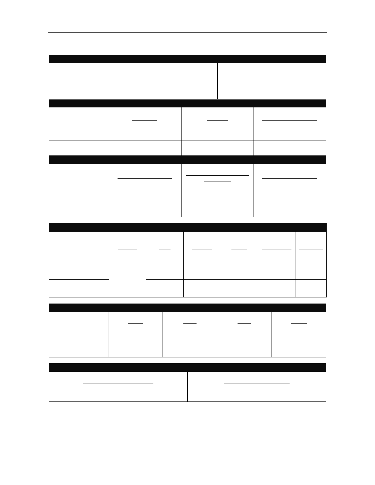
TECHNICAL SPECIFICATIONS – DURAWELD
TM
350/500
INPUT – THREE PHASE ONLY
DURAWELD
TM
350/500
Standard Voltage/Phase/Frequency
380V ~ 415V(±10%)/3/50 Hz
Input Power @ 60% Duty Cycle
DURAWELD
TM
350 18.1KVA/14.1KW
DURAWELD
TM
500 30.6KVA/25.3KW
RATED OUTPUT – DC ONLY
DURAWELD
TM
350
Duty Cycle
60%
100%
Amperes
350A
270A
Volts at Rated Amperes
31.5V
27.5V
DURAWELDTM 500
60%
100%
500A
390A
39V
33.5V
* OUTPUT RANGE
DURAWELD
TM
350
Welding Current Range
50A ~ 350A
Rated Open Circuit Voltage
RMS/PEAK
53V/60V
Welding Voltage Range
16.5 V ~ 31.5V
DURAWELDTM 500 50A ~ 500A 60V/66V 16.5V ~ 39V
RECOMMENDED INPUT WIRE AND FUSE SIZES
DURAWELDTM 350
Input
Voltage/
Frequency
(Hz)
342V ~
456.5V/
50Hz or
60Hz
Maximum
Input
Ampere
30A
Maximum
Effective
Supply
Current
22A
60°C Copper
Wire in
Conduct
Sizes
10 mm
2
Fuse or
Breaker Size
(Super Lag)
50A
Grounding
Conductor
Size
6mm2
DURAWELDTM 500 48A 38A 16 mm2 80A 10mm2
PHYSICAL DIMENSIONS
DURAWELD
TM
350
Height
755mm
Width
500mm
Depth
590mm
Weight
116Kg
DURAWELDTM 500 755mm 500mm 590mm 154Kg
Temperature Range
Operating Temperature Range
-10°C ~ +40°C
Storage Temperature Range
-25°C ~ +55°C
*Note: The output range is measured under conventional welding condition per IEC 60974-1:2000 standard.
For any maintenance or repair operation it is recommended to contact the nearest technical service center or directly
consult the machine division of the Shanghai Lincoln Electric Co. Ltd.. Maintenance or repairs performed by
unauthorized service centers or personnel will void the manufacturer’s warranty.
A-2
INSTALLATION
A-2
DURAWELD
TM
350/500
SAFETY PRECAUTIONS
Read the entire installation section before starting
installation.
ELECTRIC SHOCK can kill.
Only qualified personnel
should perform this installation.
Turn the input power OFF
at the main switch or fuse box
before working on this
equipment. Turn off the input power to any other
equipment connected to the welding system at
the main switch or fuse box before working on
the equipment.
Do not touch electrically “Hot” parts.
Always connect the DURAWELDTM grounding lug
(located at the rear of the case) to a proper safety
(Earth) ground.
DURAWELDTM must only be used on three-
phase, MEN input power.
SELECT SUITABLE LOCATION
This power source should not be subjected to rain, nor
should any parts of it be submerged in water. Doing so
may cause improper operation as well as pose a safety
hazard. The best practice is to keep the machine in a
dry, sheltered area.
The bottom of machine must always be placed on a
firm, secure, level surface. There is a danger of the
machine toppling over if this precaution is not
taken.
Place the welder where clean cool air can freely
circulate in through the side and back louvers and out
through the case bottom. Water dust or any foreign
material that can be drawn into the welder should be
kept a minimum. Failure to observe these precautions
can result in excessive operating temperatures and
nuisance shutdowns.
Locate the DURAWELD
TM
machine away from radio
controlled machinery. Normal operation of the welder
may adversely affect the operation of RF controlled
equipment, which may result in bodily injury or damage
to the equipment.
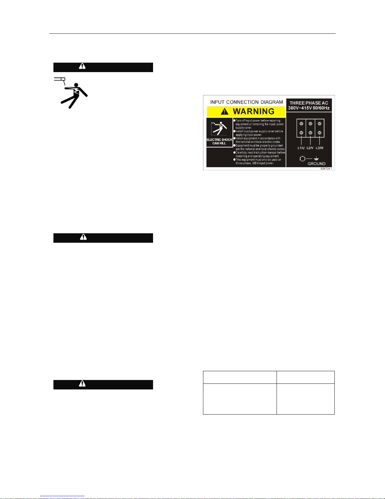
INPUT POWER AND GROUNDING
CONNECTION
Only a qualified electrician should connect the
input leads to the DURAWELD
TM
. Connections
should be made in accordance with the connection
diagram. Failure to do so may result in bodily injury
or death.
Open the input box on the rear of the case. Use a
three-phase supply line, the three live wires should go
through the three holes of the input wire holder and be
securely clamped and fixed. Connect L1, L2, L3 and
ground according to the Input Supply Connection
Diagram decal, refer to Figure A.1 on this page.
FIGURE A.1 – Input Supply Connection Diagram
The DURAWELDTM is supplied connected for 50Hz
input. In regions where the frequency of electricity is
60HZ, the DURAWELDTM machine can identify the 60
HZ frequency automatically and work in terms of this
frequency.
Make sure the amount of power available from the input
connection is adequate for normal operation of the
machine. Refer to the Technical Specifications at the
beginning of this Installation section for recommended
fuse and wire sizes. Fuse the input circuit with the
recommended super lag fuse or delay type breakers.
Using fuses or circuit breakers smaller than
recommended may result in “nuisance” shut-offs from
welder inrush currents, even if the machine is not being
used at high currents.
OUTPUT AND WIRE FEEDER
CONNECTIONS
Connect a work lead of sufficient size and length (Per
Table A.1) between the Negative Output terminal on the
power source and the work. Be sure the connection to
the work makes tight metal-to-metal electrical contact.
To avoid interference problems with other equipment
and to achieve the best possible operation, route all
cables directly to the work and wire feeder. Avoid
excessive lengths and do not coil excess cable.
Minimum work and electrode cable sizes are as follows:
TABLE A.1
Current (60% Duty Cycle) Minimum Copper
Work Cable Size
200A
300A
400A
500A
Up To 30m Length
30 mm
2
50 mm
2
70 mm
2
95 mm
2
Note: Recommended cable sizes may vary due to
different cable quality. The overall voltage pressure of
grounding and welding cables is no more than 4V under
rated current.
WARNING
CAUTION
WARNING
A-3
INSTALLATION
A-3
DURAWELD
TM
350/500
PWF wire feeder connection instructions
(See Figure A. 2)
Turn the DURAWELD
TM
power switch “OFF”.
Connect the control cable from the PWF/LWF feeder
to the 6-pin connector. 2 wire feeder models are:
LWF-2/LWF-4Plus
Connect the electrode cable to the Positive Output
terminal.
For secure electrical connections, the Nuts
connecting the output terminals and cables must
be tightened. Damage to output studs and poor
performance may occur, if this instruction is not
followed.
GUN AND CABLE INSTALLATION
Optional guns with various cable length can be used
with the DURAWELD
TM
.
Turn the welder power switch off before installing
gun and cable.
Gun and cable assembly installation instruction
Unscrew the hexagon head screw in front of the wire
drive unit (inside wire feed compartment) until tip of
screw no longer protrudes into gun opening as seen
from front of wire feeder.
Insert the male end of gun cable into the female
casting. Make sure connector is fully inserted and
tighten the hexagon head screw.
Connect the two-pin gun trigger connector from the
gun and cable to the mating receptacle, then tighten
the retaining ring.
Connect the gas connector to the mating receptacle
at front of wire feeder, and tighten the copper
retaining ring.
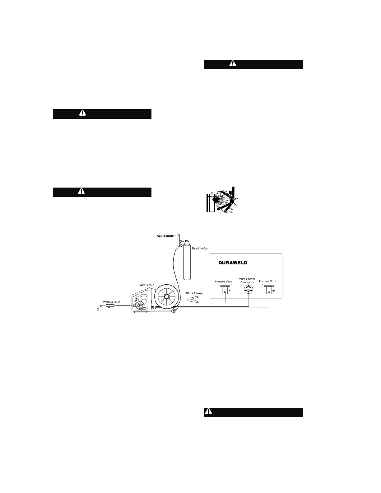
CONNECTING SHIELDING GAS
DURAWELD
TM
supports MIG/MAG, FCAW-GS/SS
Welding Process.
User must provide gas cylinder of appropriate type
shielding gas for the process being used with the
DURAWELD™.
CYLINDER may explode if damaged.
Gas under pressure is explosive. Always keep
gas cylinders in an upright position and always
keep chained to undercarriage or stationary
support.
Install shielding gas supply as follows:
Remove the cylinder cap. Inspect the cylinder valve
and regulator for damaged threads, dirt, dust, oil or
grease. Remove dust and dirt with a clean cloth. DO
NOT ATTACH THE REGULATOR IF OIL, GREASE
OR DAMAGE IS PRESENT! Inform your gas
supplier of this condition. Oil or grease in the
presence of high pressure oxygen is explosive.
Stand to one side away from the outlet and open the
cylinder valve for an instant. This blows away any
dust or dirt which may have accumulated in the valve
outlet.
Attach the flow regulator to
the cylinder valve and tighten the
union nut(s) securely with a
wrench.
NOTE: When connecting to a CO
2
cylinder, please select a CO
2
Regulator Heater for the
prevention of ice build up. Failure to do so, may result
in poor welding performance. The power cord of the
gas heater must be plugged into the receptacle on the
rear of the DURAWELD
TM
case.
Attach the end of the inlet gas hose, from the wire
feeder, to the outlet fitting of the flow regulator, and
tighten the union nuts securely with a wrench.
Before opening the cylinder valve, turn the regulator
adjusting knob counterclockwise until the adjusting
spring pressure is released.
Standing to one side, open the cylinder valve slowly
a fraction of a turn. When the cylinder pressure
gauge pointer stops moving, open the valve fully.
Never stand directly in front of or behind the flow
regulator when opening the cylinder valve. Always
stand to the side.
The flow meter is adjustable. Adjust it to the flow rate
recommended for the weld procedure.
CAUTION
WARNING
WARNING
WARNING
FIGURE A. 2 – OUTPUT AND WIRE FEEDER CONNECTIONS
B-1
OPERATION
B-1
DURAWELD
TM
350/500
SAFETY PRECAUTIONS
ELECTRIC SHOCK can kill.
Do not touch electrically
live parts or electrode with skin
or wet clothing.
Insulate yourself from
work and ground.
Always wear dry
insulating
gloves.
FUMES AND GASES can be
dangerous.
Keep your head out of
fumes.
Use ventilation or exhaust
to remove fumes from breathing
zone.
WELDING SPARKS can cause
fire or explosion.
Keep flammable material
away.
Do not weld on closed
containers.
ARC RAYS can burn eyes and
skin.
Wear eyes, ear and body
protection.
PLEASE SEE ADDITIONAL WARNING
INFORMATION AT THE FRONT OF THIS
OPERATOR’S MANUAL.
GENERAL DESCRIPTION
The DURAWELDTM is a semiautomatic DC arc welding
machine offering CV DC welding. It is rated as follows:
DURAWELD
TM
350: 350amps, 31.5volts at 60% duty
cycle.
DURAWELD
TM
500: 500amps, 39volts at 60% duty
cycle.
DUTY CYCLE
The duty cycle of a welding machine is the percentage
of time in a 10 minute cycle at which the welder can
operate the machine at rated welding current.
60% duty cycle:
Weld for 6 minutes Break for 4 minutes
Excessive extension of the duty cycle will cause the
thermal protection circuits to activate.
The DURAWELD
TM
machine is equipped with a
thermostat overheating protection device. When the
machine detects overheating, the output will turn off,
and the Thermal Indicator Light will turn “ON“. When
the machine has cooled to a safe temperature, the
Thermal Indicator Light will go out and the machine will
resume normal operation.
Note: For safety reasons the machine will not come out
of thermal shutdown if the trigger on the welding gun
has not been released.
Wait for machine
to cool down
Or decrease
duty cycle
OPERATIONAL FEATURES AND
CONTROLS
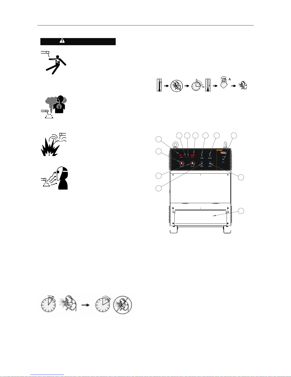
Front Panel (Please see figure B.1)
123456
7
8
9
10
11
12
1. ON/OFF POWER SWITCH
After input power is connected and the power switch is
turned on, the digit meters are active. Voltage meter will
show pre-set value.
2. Wire selection
Solid and Flux-cored
3.GAS SELECTION
There is a selection switch on CO2 and mix gas
according to actual welding condition.
WARNING
B-3
OPERATION
B-3
DURAWELD
TM
350/500
4. VOLTAGE METER
Actual welding voltage will be shown in welding state;
pre-set value will be shown if no welding operation.
Crater pre-set value will be shown when any crater
parameter is adjusted.
5. SYNERGIC STATE INDICAITOR
The indicator will be lighted when this function is turned
on to indicate synergic function.
Otherwise, it will be in the independent adjustment
state.
6. CRATER ADJUSTMENT INDICATOR
The indicator will be lighted when adjusting crator
voltage or current to indicate pre-set value of crater
voltage and current.
7. AMPERAGE METER
During the welding process, this meter displays the
welding current value. This meter displays pre-set value
if there is no welding operation; Crator current pre-set
value will be shown when crator parameter is adjusted.
8. Crater Current Potentiometer
This knob adjusts the output current (wire feed speed),
when the Dura Weld
TM
machine is in crater mode.
9. Crater Voltage & spot weld time Potentiometer
This knob adjusts the value of output voltage, when the
Dura Weld
TM
weld mode switch is selected to 4-step.
This Knob adjust the persistence time of spot weld,
when the weld mode switch is selected to spot
weld.(Only for Duraweld 350)
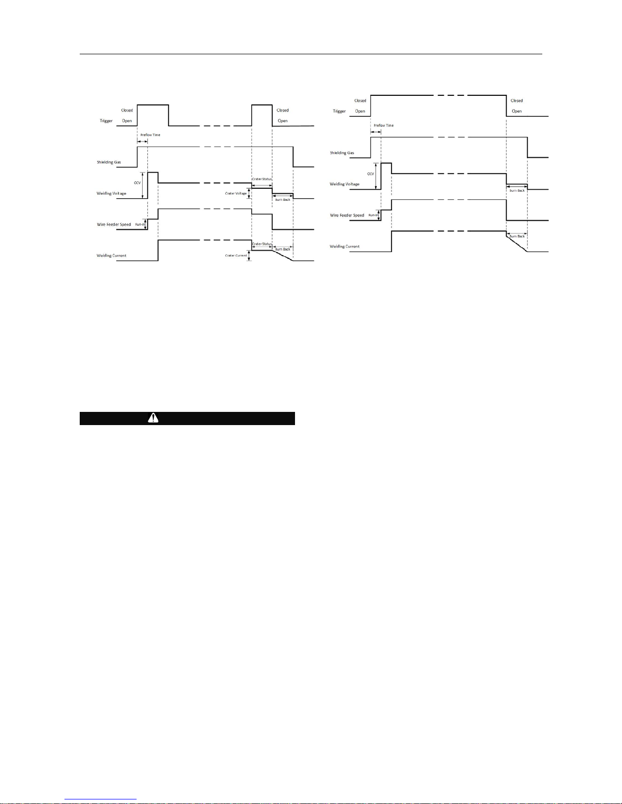
10. Weld Mode SWITCH
This switch enables the selection of 2-step or 4-step
mode(Enable or disable the crater mode) by this switch.
And also can use this switch enable the spot weld
mode on Duraweld 350.
NOTE: The DURAWELD
TM
machine also features a
Crater mode. During 2-step mode, there is no crater
output. During the 4-step mode, after the welder
activates the trigger, the DURAWELD shifts to crater
mode.
Please see FIGURE B.4 for an understanding of the
detailed working process for 2 and 4 step modes.
11. WIRE DIAMETER SELECTION
There are three diameter selection switch;
For Duraweld 500,1.0, 1.2, 1.6 can be select with this
switch.
For Duraweld 350,1.2,1.0, 0.8 can be select with this
switch.
It can be set according to actual welding request. Preset current is more accurate when the wire diameter
above is selected. Otherwise, it will stray from pre-set
value.
12. PROTECTION DOOR
This door is used to protect the output terminal and wire
feeder connector. Only after turning off the power,
Open protection door to connect the welding cables and
LWF feeder.
Do NOT operate the DURAWELD
TM
machine with
this door open.
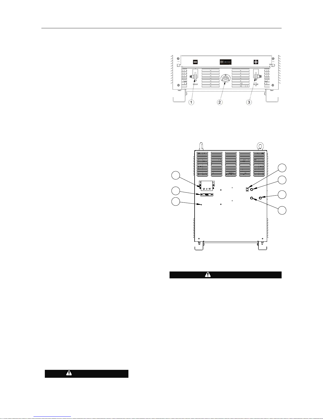
Output Stud
(Fig B.2)
1 Negtive Stud.
2 The connector of Wire feeder.
3 Positive Stud.
REAR PANEL (FIGURE B.3)
1
2
3
4
6
7
5
1. INPUT POWER PROTECTIVE BOX
Insulation box is used to cover the input connections,
offering insulating protection to the operator.
WARNING
Insulation box must be installed before turning on
the main power supply.
2. INPUT CABLE HOLDING BRACKET
This bracket holds the three phase power cables
securely.
3. GROUND CABLE CONNECTION
Connect the input earth cable to the rear of the case. A
earth Hex. Screw is located on the lower rear of the
case. Secure the earth cable lug-end with the screw
into the case hole.
4. WIRE FEEDER 8A FUSE AND FUSE HOLDER
250V 8A fuse is used to protect wire feeder control
circuit from short circuit so that control board is not
damaged.
WARNING
B-3
OPERATION
B-3
DURAWELD
TM
350/500
5. GAS HEATING 2A FUSE AND FUSE HOLDER
This machine is equipped with AC220V(200W) heating
power. This fuse is used to protect heating circuit.
6. GAS HEATING SOCKET
This is output socket of Max Aux 220v power, used
to connect with gas heater.
WARNING
Only 220V gas heater could be connected at the plug of
low voltage, do not connect other electrical device,
otherwise, the machine could be damaged.
7. 2 A FUSE FOR CONTROL BOARD
An 2-amp slow blow fuse on the machine’s rear
panel protects the control board and contactor from
excessive overloads or short circuits.
Function and schedule See B.4
FIGURE B.4
FOUR STEP
TWO STEP
 Loading...