

Lincoln Electric DUAL VANTAGE 700, DUAL VANTAGE 700-I, Dual Voltage 700 Operator's Manual
Operator’s Manual
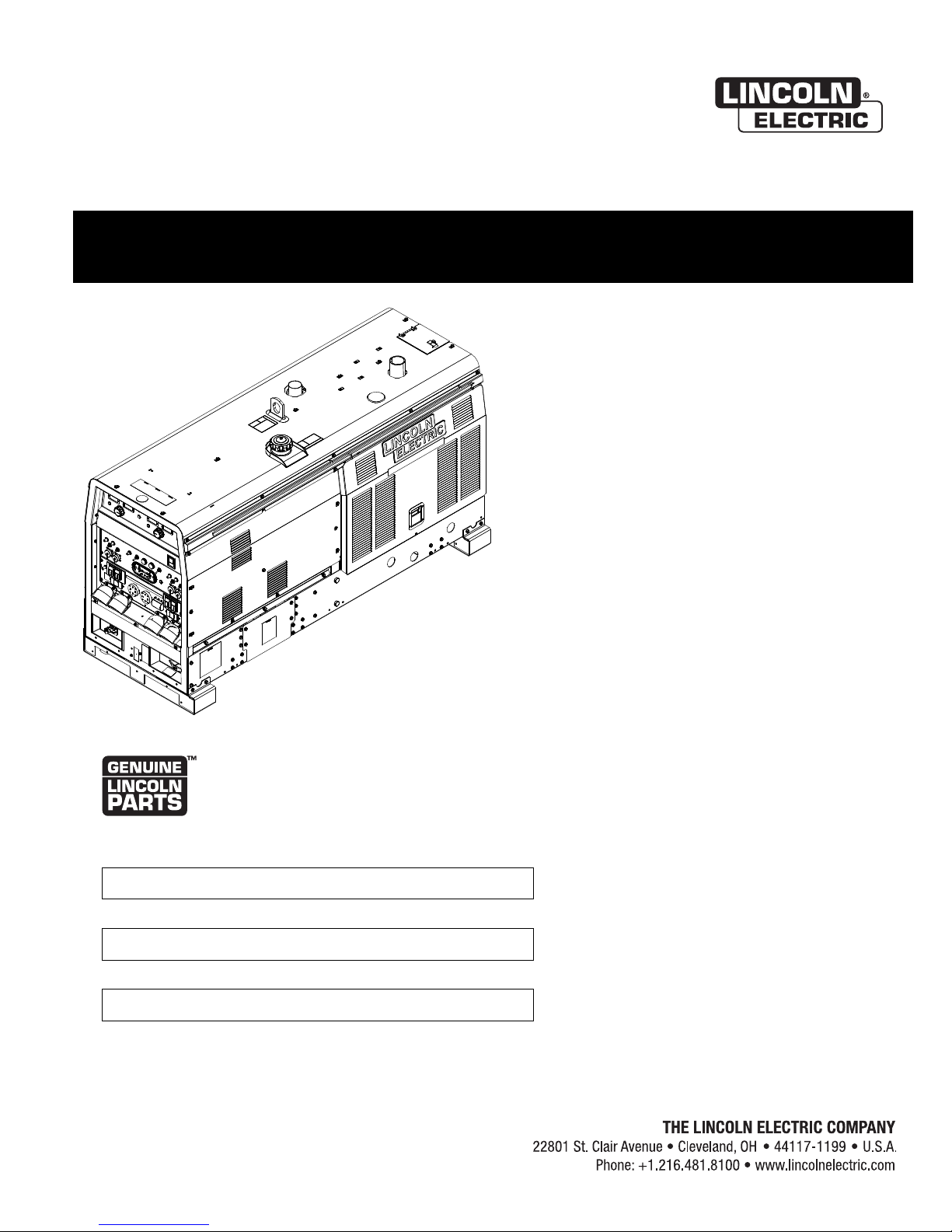
DUAL VANTAGE ® 700
For use with machines having Code Numbers:
12320
Register your machine:
www.lincolnelectric.com/register
Authorized Service and Distributor Locator:
www.lincolnelectric.com/locator
Save for future reference
Date Purchased
Code: (ex: 10859)
Serial: (ex: U1060512345)
IM10174 | Issue D ate July-16
© Lincoln Global, Inc. All Rights Reserved.
Need Help? Call 1.888.935.3877
to talk to a Service Representative
Hours of Operation:
8:00 AM to 6:00 PM (ET) Mon. thru Fri.
After hours?
Use “Ask the Experts” at lincolnelectric.com
A Lincoln Service Representative will contact you
no later than the following business day.
For Service outside the USA:
Email: globalservice@lincolnelectric.com
THANK YOU FOR SELECTING
A QUALITY PRODUCT BY
LINCOLN ELEC TRIC.
PLEASE EXAMINE CARTON AND EQUIPMENT FOR
DAMAGE IMMEDIATELY
When this equipment is shipped, title passes to the purchaser
upon receipt by the carrier. Consequently, claims for material
damaged in shipment must be made by the purchaser against the
transportation company at the time the shipment is received.
SAFETY DEPENDS ON YOU
Lincoln arc welding and cutting equipment is designed and built
with safety in mind. However, your overall safety can be increased
by proper installation ... and thoughtful operation on your part.
DO NOT INSTALL, OPERATE OR REPAIR THIS EQUIPMENT
WITHOUT READING THIS MANUAL AND THE SAFETY
PRECAUTIONS CONTAINED THROUGHOUT. And, most importantly,
think before you act and be careful.
WARNING
This statement appears where the information must be followed
exactly to avoid serious personal injury or loss of life.
CAUTION
This statement appears where the information must be followed
to avoid minor personal injury or damage to this equipment.
KEEP YOUR HEAD OUT OF THE FUMES.
DON’T get too close to the arc.
se corrective lenses if necessary
U
to stay a reasonable distance
away from the arc.
READ and obey the Safety Data
Sheet (SDS) and the warning label
that appears on all containers of
welding materials.
USE ENOUGH VENTILATION or
exhaust at the arc, or both, to
keep the fumes and gases from
your breathing zone and the general area.
IN A LARGE ROOM OR OUTDOORS, natural ventilation may be
adequate if you keep your head out of the fumes (See below).
USE NATURAL DRAFTS or fans to keep the fumes away
from your face.
If you de velop unusual symptoms, see your supervisor.
Perhaps the welding atmosphere and ventilation system
should be checked.
WEAR CORRECT EYE, EAR &
BODY PROTECTION
PROTECT your eyes and face with welding helmet
properly fitted and with proper grade of filter plate
(See ANSI Z49.1).
PROTECT your body from welding spatter and arc
flash with protective clothing including woolen
clothing, flame-proof apron and gloves, leather
leggings, and high boots.
PROTECT others from splatter, flash, and glare
with protective screens or barriers.
IN SOME AREAS, protection from noise may be appropriate.
BE SURE protective equipment is in good condition.
Also, wear safety glasses in work area
AT ALL TIMES.
SPECIAL SITUATIONS
DO NOT WELD OR CUT containers or materials which previously
had been in contact with hazardous substances unless they are
properly cleaned. This is extremely dangerous.
DO NOT WELD OR CUT painted or plated parts unless special
precautions with ventilation have been taken. They can release
highly toxic fumes or gases.
Additional precautionary measures
PROTECT compressed gas cylinders from excessive heat,
mechanical shocks, and arcs; fasten cylinders so they cannot fall.
BE SURE cylinders are never grounded or part of an
electrical circuit.
REMOVE all potential fire hazards from welding area.
ALWAYS HAVE FIRE FIGHTING EQUIPMENT READY FOR
IMMEDIATE USE AND KNOW HOW TO USE IT.
Safety 01 of 04 - 06/15/2016
SECTION A:
WARNINGS
CALIFORNIA PROPOSITION 65 WARNINGS
Diesel Engines
Diesel engine exhaust and some of its constituents are known
to the State of California to cause cancer, birth defects, and other
reproductive harm.
Gasoline Engines
The engine exhaust from this product contains chemicals known
to the State of California to cause cancer, birth defects, or other
reproductive harm.
ARC WELDING CAN BE HAZARDOUS. PROTECT
YOURSELF AND OTHERS FROM POSSIBLE SERIOUS
INJURY OR DEATH. KEEP CHILDREN AWAY.
PACEMAKER WEARERS SHOULD CONSULT WITH
THEIR DOCTOR BEFORE OPERATING.
Read and understand the following safety highlights. For
additional safety information, it is strongly recommended
that you purchase a copy of “Safety in Welding & Cutting ANSI Standard Z49.1” from the American Welding Society,
P.O. Box 351040, Miami, Florida 33135 or CSA Standard
W117.2-1974. A Free copy of “Arc Welding Safety” booklet
E205 is available from the Lincoln Electric Company,
22801 St. Clair Avenue, Cleveland, Ohio 44117-1199.
BE SURE THAT ALL INSTALLATION, OPERATION,
MAINTENANCE AND REPAIR PROCEDURES ARE
PERFORMED ONLY BY QUALIFIED INDIVIDUALS.
SAFETY
1.d. Keep all equipment safety guards, covers
and devices in position and in good repair.
Keep hands, hair, clothing and tools away
from V-belts, gears, fans and all other
moving parts when starting, operating or
repairing equipment.
1.e. In some cases it may be necessary to remove safety guards to
perform required maintenance. Remove guards only when
necessary and replace them when the maintenance requiring
heir removal is complete. Always use the greatest care when
t
working near moving parts.
1.f. Do not put your hands near the engine fan. Do not attempt to
override the governor or idler by pushing on the throttle control
rods while the engine is running.
1.g. To prevent accidentally starting gasoline engines while turning
the engine or welding generator during maintenance work,
disconnect the spark plug wires, distributor cap or magneto wire
as appropriate.
1.h. To avoid scalding, do not remove the radiator
pressure cap when the engine is
hot.
ELECTRIC AND
MAGNETIC FIELDS MAY
BE DANGEROUS
2.a. Electric current flowing through any conductor
causes localized Electric and Magnetic Fields (EMF).
Welding current creates EMF fields around welding cables
and welding machines
FOR ENGINE POWERED
EQUIPMENT.
1.a. Turn the engine off before troubleshooting
and maintenance work unless the
maintenance work requires it to be running.
1.b. Operate engines in open, well-ventilated
areas or vent the engine exhaust fumes outdoors.
1.c. Do not add the fuel near an open flame
welding arc or when the engine is running.
Stop the engine and allow it to cool before
refueling to prevent spilled fuel from
vaporizing on contact with hot engine parts
and igniting. Do not spill fuel when filling
tank. If fuel is spilled, wipe it up and do not start engine until
fumes have been eliminated.
2.b. EMF fields may interfere with some pacemakers, and
welders having a pacemaker should consult their physician
before welding.
2.c. Exposure to EMF fields in welding may have other health effects
which are now not known.
2.d. All welders should use the following procedures in order to
minimize exposure to EMF fields from the welding circuit:
2.d.1. Route the electrode and work cables together - Secure
them with tape when possible.
2.d.2. Never coil the electrode lead around your body.
2.d.3. Do not place your body between the electrode and work
cables. If the electrode cable is on your right side, the
work cable should also be on your right side.
2.d.4. Connect the work cable to the workpiece as close as possible to the area being welded.
2.d.5. Do not work next to welding power source.
Safety 02 of 04 - 06/15/2016
SAFETY
ELECTRIC SHOCK
CAN KILL.
3.a. The electrode and work (or ground) circuits are
electrically “hot” when the welder is on. Do
not touch these “hot” parts with your bare skin or wet clothing.
Wear dry, hole-free gloves to insulate hands.
3.b. Insulate yourself from work and ground using dry insulation.
Make certain the insulation is large enough to cover your full area
f physical contact with work and ground.
o
In addition to the normal safety precautions, if
welding must be performed under electrically
hazardous conditions (in damp locations or while
wearing wet clothing; on metal structures such as
floors, gratings or scaffolds; when in cramped
positions such as sitting, kneeling or lying, if there
is a high risk of unavoidable or accidental contact
with the workpiece or ground) use the following
equipment:
• Semiautomatic DC Constant Voltage (Wire) Welder.
• DC Manual (Stick) Welder.
• AC Welder with Reduced Voltage Control.
3.c. In semiautomatic or automatic wire welding, the electrode,
electrode reel, welding head, nozzle or semiautomatic welding
gun are also electrically “hot”.
3.d. Always be sure the work cable makes a good electrical
connection with the metal being welded. The connection should
be as close as possible to the area being welded.
3.e. Ground the work or metal to be welded to a good electrical (earth)
ground.
3.f. Maintain the electrode holder, work clamp, welding cable and
welding machine in good, safe operating condition. Replace
damaged insulation.
3.g. Never dip the electrode in water for cooling.
3.h. Never simultaneously touch electrically “hot” parts of electrode
holders connected to two welders because voltage
two can be the total of the open circuit voltage of both
welders.
3.i. When working above floor level, use a safety belt to protect
yourself from a fall should you get a shock.
between the
ARC RAYS CAN BURN.
4.a. Use a shield with the proper filter and cover plates to protect your
eyes from sparks and the rays of the arc when welding or
observing open arc welding. Headshield and filter lens should
conform to ANSI Z87. I standards.
4.b. Use suitable clothing made from durable flame-resistant material
to protect your skin and that of your helpers from the arc rays.
4.c. Protect other nearby personnel with suitable, non-flammable
screening and/or warn them not to watch the arc nor expose
themselves to the arc rays or to hot spatter or metal.
FUMES AND GASES
CAN BE DANGEROUS.
5.a. Welding may produce fumes and gases
hazardous to health. Avoid breathing these fumes and gases.
When welding, keep your head out of the fume. Use enough
ventilation and/or exhaust at the arc to keep fumes and gases
away from the breathing zone. When welding hardfacing
(see instructions on container or SDS) or on lead
or cadmium plated steel and other metals or
coatings which produce highly toxic fumes, keep
exposure as low as possible and within applicable
OSHA PEL and ACGIH TLV limits using local
exhaust or mechanical ventilation unless exposure
assessments indicate otherwise. In confined
spaces or in some circumstances, outdoors, a
respirator may also be required. Additional
precautions are also required when welding
on galvanized steel.
5. b. The operation of welding fume control equipment is affected by
various factors including proper use and positioning of the
equipment, maintenance of the equipment and the specific
welding procedure and application involved. Worker exposure
level should be checked upon installation and periodically
thereafter to be certain it is within applicable OSHA PEL and
ACGIH TLV limits.
5.c. Do not weld in locations near chlorinated hydrocarbon vapors
coming from degreasing, cleaning or spraying operations. The
heat and rays of the arc can react with solvent vapors to form
phosgene, a highly toxic gas, and other irritating products.
3.j. Also see It ems 6.c. and 8.
5.d. Shielding gases used for arc welding can displace air and
cause
injury or death. Always use enough ventilation, especially in
confined areas, to insure breathing air is safe.
5.e. Read and understand the manufacturer’s instructions for this
equipment and the consumables to be used, including the
Safety Data Sheet (SDS) and follow your employer’s safety
practices. SDS forms are available from your welding
distributor or from the manufacturer.
5.f. Also see item 1.b.
Safety 03 of 04 - 06/15/2016
SAFETY
WELDING AND CUTTING
SPARKS CAN CAUSE
FIRE OR EXPLOSION.
6.a. Remove fire hazards from the welding area. If
this is not possible, cover them to prevent the welding sparks
rom starting a fire. Remember that welding sparks and hot
f
materials from welding can easily go through small cracks and
openings to adjacent areas. Avoid welding near hydraulic lines.
Have a fire extinguisher readily available.
6.b. Where compressed gases are to be used at the job site, special
precautions should be used to prevent hazardous situations.
Refer to “Safety in Welding and Cutting” (ANSI Standard Z49.1)
and the operating information for the equipment being used.
6.c. When not welding, make certain no part of the electrode circuit is
touching the work or ground. Accidental contact can cause
overheating and create a fire hazard.
6.d. Do not heat, cut or weld tanks, drums or containers until the
proper steps have been taken to insure that such procedures
will not cause flammable or toxic vapors from substances inside.
They can cause an explosion even though they have been
“cleaned”. For information, purchase “Recommended Safe
Practices for the Preparation for Welding and Cutting of
Containers and Piping That Have Held Hazardous Substances”,
AWS F4.1 from the American Welding Society
(see address above).
6.e. Vent hollow castings or containers before heating, cutting or
welding. They may explode.
6.f. Sparks and spatter are thrown from the welding arc. Wear oil free
protective garments such as leather gloves, heavy shirt, cuffless
trousers, high shoes and a cap over your hair. Wear ear plugs
when welding out of position or in confined places. Always wear
safety glasses with side shields when in a welding area.
6.g. Connect the work cable to the work as close to the welding area
as practical. Work cables connected to the building framework or
other locations away from the welding area increase the
possibility of the welding current passing through lifting chains,
crane cables or other alternate circuits. This can create fire
hazards or overheat lifting chains or cables until they fail.
6.h. Also see item 1.c.
CYLINDER MAY EXPLODE IF
DAMAGED.
7.a. Use only compressed gas cylinders containing
the correct shielding gas for the process used
and properly operating regulators designed for
the gas and pressure used. All hoses, fittings,
tc. should be suitable for the application and
e
maintained in good condition.
7.b. Always keep cylinders in an upright position securely chained to
an undercarriage or fixed support.
7.c. Cylinders should be located:
• Away from areas where they may be struck or subjected
to physical damage.
• A safe distance from arc welding or cutting operations
and any other source of heat, sparks, or flame.
7.d. Never allow the electrode, electrode holder or any other
electrically “hot” parts to touch a cylinder.
7.e. Keep your head and face away from the cylinder valve outlet
when opening the cylinder valve.
7.f. Valve protection caps should always be in place and hand tight
except when the cylinder is in use or connected for use.
7.g. Read and follow the instructions on compressed gas cylinders,
associated equipment, and CGA publication P-l, “Precautions for
Safe Handling of Compressed Gases in Cylinders,” available from
the Compressed Gas Association, 14501 George Carter Way
Chantilly, VA 20151.
FOR ELECTRICALLY
POWERED EQUIPMENT.
8.a. Turn off input power using the disconnect
switch at the fuse box before working on
the equipment.
8.b. Install equipment in accordance with the U.S. National Electrical
Code, all local codes and the manufacturer’s recommendations.
6.I. Read and follow NFPA 51B “Standard for Fire Prevention During
Welding, Cutting and Other Hot Work”, available from NFPA, 1
Batterymarch Park, PO box 9101, Quincy, MA 022690-9101.
6.j. Do not use a welding power source for pipe thawing.
8.c. Ground the equipment in accordance with the U.S. National
Electrical Code and the manufacturer’s recommendations.
Refer to
http://www.lincolnelectric.com/safety
for additional safety information.
Safety 04 of 04 - 06/15/2016

SAFETYDUAL VANTAGE®700
Electromagnetic Compatibility (EMC)
onformance
C
Products displaying the CE mark are in conformity with European Community Council Directive of 15 Dec
2004 on the approximation of the laws of the Member States relating to electromagnetic compatibility,
2004/108/EC. It was manufactured in conformity with a national standard that implements a harmonized
standard: EN 60974-10 Electromagnetic Compatibility (EMC) Product Standard for Arc Welding Equipment.
It is for use with other Lincoln Electric equipment. It is designed for industrial and professional use.
Introduction
All electrical equipment generates small amounts of electromagnetic emission. Electrical emission may be
transmitted through power lines or radiated through space, similar to a radio transmitter. When emissions
are received by other equipment, electrical interference may result. Electrical emissions may affect many
kinds of electrical equipment; other nearby welding equipment, radio and TV reception, numerical controlled
machines, telephone systems, computers, etc. Be aware that interference may result and extra precautions
may be required when a welding power source is used in a domestic establishment.
Installation and Use
The user is responsible for installing and using the welding equipment according to the manufacturer’s
instructions. If electromagnetic disturbances are detected then it shall be the responsibility of the user of the
welding equipment to resolve the situation with the technical assistance of the manufacturer. In some cases
this remedial action may be as simple as earthing (grounding) the welding circuit, see Note. In other cases it
could involve construction of an electromagnetic screen enclosing the power source and the work complete
with associated input filters. In all cases electromagnetic disturbances must be reduced to the point where
they are no longer troublesome.
Note: The welding circuit may or may not be earthed for safety reasons according to national
codes. Changing the earthing arrangements should only be authorized by a person who is
competent to access whether the changes will increase the risk of injury, e.g., by allowing
parallel welding current return paths which may damage the earth circuits of other equipment.
Assessment of Area
Before installing welding equipment the user shall make an assessment of potential electromagnetic problems in the surrounding area. The following shall be taken into account:
a) other supply cables, control cables, signaling and telephone cables; above, below and adjacent to the
welding equipment;
b) radio and television transmitters and receivers;
c) computer and other control equipment;
d) safety critical equipment, e.g., guarding of industrial equipment;
e) the health of the people around, e.g., the use of pacemakers and hearing aids;
f) equipment used for calibration or measurement
g) the immunity of other equipment in the environment. The user shall ensure that other equipment being
used in the environment is compatible. This may require additional protection measures;
h) the time of day that welding or other activities are to be carried out.
2

SAFETYDUAL VANTAGE®700
Electromagnetic Compatibility (EMC)
he size of the surrounding area to be considered will depend on the structure of the building and other
T
activities that are taking place. The surrounding area may extend beyond the boundaries of the premises.
Methods of Reducing Emissions
Mains Supply
Welding equipment should be connected to the mains supply according to the manufacturer’s recommendations. If interference occurs, it may be necessary to take additional precautions such as filtering of the mains
supply. Consideration should be given to shielding the supply cable of permanently installed welding equipment, in metallic conduit or equivalent. Shielding should be electrically continuous throughout its length. The
shielding should be connected to the welding power source so that good electrical contact is maintained
between the conduit and the welding power source enclosure.
Maintenance of the Welding Equipment
The welding equipment should be routinely maintained according to the manufacturer’s recommendations.
All access and service doors and covers should be closed and properly fastened when the welding equipment is in operation. The welding equipment should not be modified in any way except for those changes
and adjustments covered in the manufacturers instructions. In particular, the spark gaps of arc striking and
stabilizing devices should be adjusted and maintained according to the manufacturer’s recommendations.
Welding Cables
The welding cables should be kept as short as possible and should be positioned close together, running at
or close to floor level.
Equipotential Bonding
Bonding of all metallic components in the welding installation and adjacent to it should be considered.
However, metallic components bonded to the work piece will increase the risk that the operator could
receive a shock by touching these metallic components and the electrode at the same time. The operator
should be insulated from all such bonded metallic components.
Earthing of the Workpiece
Where the workpiece is not bonded to earth for electrical safety, not connected to earth because of its size
and position, e.g., ships hull or building steelwork, a connection bonding the workpiece to earth may reduce
emissions in some, but not all instances. Care should be taken to prevent the earthing of the workpiece
increasing the risk of injury to users, or damage to other electrical equipment. Where necessary, the connection of the workpiece to earth should be made by a direct connection to the workpiece, but in some countries
where direct connection is not permitted, the bonding should be achieved by suitable capacitance, selected
according to national regulations.
Screening and Shielding
Selective screening and shielding of other cables and equipment in the surrounding area may alleviate problems of interference. Screening of the entire welding installation may be considered for special
applications
1.
_________________________
1
Portions of the preceding text are contained in EN 60974-10: “Electromagnetic Compatibility (EMC) product standard for arc welding equipment.”
3

TABLE OF CONTENTSDUAL VANTAGE®700
Page
Installation.......................................................................................................................Section A
Technical Specifications.......................................................................................................A-1
Safety Precautions ........................................................................................................A-2
VRD (Voltage Reduction Device)..................................................................................A-2
Location and Ventilation................................................................................................A-2
Storing...........................................................................................................................A-2
Stacking ........................................................................................................................A-3
Angle of Operation ........................................................................................................A-3
Lifting.............................................................................................................................A-3
High Altitude Operation .................................................................................................A-3
High Temperature Operation ........................................................................................A-3
Towing...........................................................................................................................A-3
Vehicle Mounting...........................................................................................................A-3
Pre-Operation Engine Service..............................................................................................A-4
Oil..................................................................................................................................A-4
Fuel and Fuel Cap.........................................................................................................A-4
Engine Coolant..............................................................................................................A-4
Battery Connection........................................................................................................A-4
Muffler Outlet Pipe ........................................................................................................A-5
Spark Arrestor ...............................................................................................................A-5
Air Cleaner Inlet Hood ..........................................................................................................A-5
Welding Terminals................................................................................................................A-5
Welding Output Cables .................................................................................................A-5
Machine Grounding.......................................................................................................A-5
Remote Control ....................................................................................................................A-6
Auxiliary Power Receptacles................................................................................................A-6
Standby Power Connections ........................................................................................A-6, A-7
Connection of Lincoln Electric Wire Feeders................................................................A-8, A-9
Connection of Wire Feeders with Control Cable (14 Pin).....................................................A-8
Connection of Across the Arc Wire Feeders ........................................................................A-9
Electrical Device use with this Product...............................................................................A-10
________________________________________________________________________________
Operation.........................................................................................................................Section B
Safety Precautions ..............................................................................................................B-1
General Description..............................................................................................................B-1
Auxiliary Power ............................................................................................................B-1
Engine Operation ..........................................................................................................B-1
Add Fuel ...............................................................................................................................B-2
Hand Primer Button..............................................................................................................B-2
Recommended Applications.................................................................................................B-2
Generator .............................................................................................................................B-2
Welding Controls ....................................................................................................B-3 thru B-4
Engine Controls....................................................................................................................B-5
Engine Operation .................................................................................................................B-6
Welder Operation ...................................................................................................B-7 thru B-9
Constant Current (CC-Stick) Welding ...........................................................................B-7
Downhill Pipe Welding ..................................................................................................B-7
TIG Welding ..................................................................................................................B-8
Typical Current Ranges for Tungsten Electrodes .........................................................B-8
Wire Welding-CV...........................................................................................................B-9
Arc Gouging ..................................................................................................................B-9
Paralleling .....................................................................................................................B-9
Auxiliary Power Operation..................................................................................................B-10
Simultaneous Welding and Auxiliary Power Loads.....................................................B-10
Extension Cord Length Recommendations.................................................................B-10
Accessories ........................................................................................................Section C
Optional Field Installed Accessories .....................................................................C-1
________________________________________________________________________
4

TABLE OF CONTENTSDUAL VANTAGE®700
Maintenance.......................................................................................................Section D
Safety Precautions ................................................................................................D-1
Routine and Periodic Maintenance .......................................................................D-1
Engine Maintenance .......................................................................................D-1
Air Filter...........................................................................................................D-1
Service Instructions for Engine Air Cleaner...........................................................D-2
Fuel Filters ......................................................................................................D-3
Cooling System...............................................................................................D-3
Battery Handling .............................................................................................D-4
Charging the Battery .............................................................................................D-4
Servicing Muffler with Internal Spark Arrester .......................................................D-4
Nameplate / Warning Decal Maintenance.............................................................D-5
Welder / Generator Maintenance ..........................................................................D-5
Engine Maintenance Components ........................................................................D-5
________________________________________________________________________
Troubleshooting ..............................................................................................Section E
How to use Troubleshooting Guide .......................................................................E-1
Troubleshooting Guide ............................................................................E-2 thru E-4
________________________________________________________________________
Connection Diagrams, Wiring Diagrams and Dimension Print...................Section F
________________________________________________________________________
Parts List .............................................................................parts@lincolnelectric.com
Content/details may be changed or updated without notice. For most current Instruction Manuals, go to
parts.lincolnelectric.com.
________________________________________________________________________
5
INSTALLATIONDUAL VANTAGE®700
INSTALLATION
TECHNICAL SPECIFICATIONS - DUAL VANTAGE®700 (K3996-2) Code 12320
INPUT - DIESEL ENGINE
Make/Model Description Speed (RPM) Displacement Starting Dry Capacities
cu. in. (ltrs.) System
4 cylinder High Idle 1860 199(3.3)
Cummins® 69 HP (51.4kw) starter (94.6 L)
B3.3T 1800 RPM Full Load 1860
Turbo Charged
Diesel Engine Low Idle 1500
(95 x 115mm) 4.0gal. (15.1L)
Bore x Stroke inch (mm)
3.74 X 4.53
RATED OUTPUT @ 104°F(40°C) - WELDER
SINGLE MODE DUAL MODE
Duty Cycle Welding Volts at Rated Duty Cycle Welding Volts at Rated
Output Amps Output Amps
100% 600 A 44 Volts 100% 300 A 32 Volts
60% 650 A 40 volts 60% 325 A 33 Volts
40% 700 A 38 volts 40% 350 A 34 Volts
OUTPUT @ 104° (40°C) – WELDER AND GENERATOR
12VDC Battery &
Radiator Coolant:
Fuel: 25 gal.
Oil: 2 gal. (7.6L)
SINGLE MODE DUAL MODE
Welding Range Welding Range
30 – 700 Amps CC/CV 30 – 400 Amps CC/CV
20 – 250 Amps TIG 20 – 250 Amps TIG
Open Circuit Voltage Open Circuit Voltage
60 MAX OCV @ 1860 RPM 60 MAX OCV @ 1860 RPM
Auxiliary Power Auxiliary Power
120/240 VAC 12kW, 60 Hz, Single Phase 120/240 VAC 12kW, 60 Hz, Single Phase
240 VAC 20kW, 60 Hz, Three Phase 240 VAC 20kW, 60 Hz, Three Phase
PHYSICAL DIMENSIONS
Height
36.9 in 28.5 in. 77.0 in. 2095 lbs.
(937 mm) (724 mm) (1956 mm) (950 kg)
(Approx.)
Lift Bail weight rating 2500 lbs. (1134 kg.) Maximum.
(1) Output rating in watts is equivalent to volt-amperes at unity power factor.
Output voltage is within +/- 10% at all loads up to rated capacity. When welding, available auxiliary power will be reduced.
(2) Top of Enclosure, add 8.3” (211mm) for exhaust pipe, also add 3.65”(93mm) for metal skid.
(3) Without metal skid.
(2)
Width
(3)
Depth Weight
A-1
INSTALLATIONDUAL VANTAGE®700
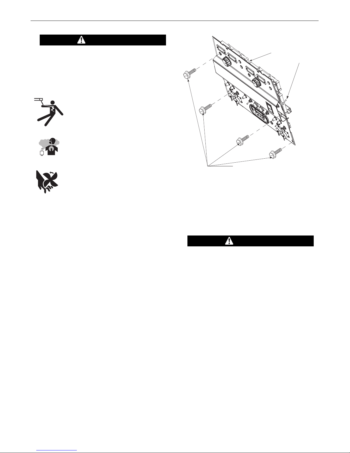
(VRD)-VOLTAGE
R
EDUCTION DEVICE
S
WITCHES LOCATED
I
N THESE AREAS.
R
EMOVE 4 FRONT PANEL
SCREWS TO ACCESS
(VRD) SWITCH
SAFETY PRECAUTIONS
WARNING
Do not attempt to use this equipment until you
have thoroughly read the engine manufacturer’s
manual supplied with your welder. It includes
important safety precautions, detailed engine
tarting, operating and maintenance instructions,
s
and parts lists.
------------------------------------------------------------------------
ELECTRIC SHOCK can kill.
• Do not touch electrically live parts or
electrode with skin or wet clothing.
• Insu l ate y o urself from wo r k an d
ground
• Always wear dry insulating gloves.
------------------------------------------------------------------------
ENGINE EXHAUST can kill.
• Use in open, well ventilated areas or
vent exhaust outside.
------------------------------------------------------------------------
MOVING PARTS can injure.
• Do not operate with doors open or
guards off.
• Stop engine before servicing.
• Keep away from moving parts.
------------------------------------------------------------------------
See additional warning information at
front of this operator’s manual.
Only qualified personnel should install,
use, or service this equipment.
VRD (VOLTAGE REDUCTION DEVICE)
The VRD feature provides additional safety in the CC-Stick
mode especially in an environment with a higher risk of
electric shock such as wet areas and hot humid sweaty conditions.
The VRD reduces the OCV (Open Circuit Voltage) at the
welding output terminals while not welding to less than 30V
DC when the resistance of the output circuit is above 200Ω
(ohms).
FIGURE A.1
LOCATION AND VENTILATION
The welder should be located to provide an unrestricted flow of clean, cool air to the cooling air inlets and to
avoid restricting the cooling air outlets. Also, locate
the welder so that the engine exhaust fumes are properly vented to an outside area.
CAUTION
DO NOT MOUNT OVER COMBUSTIBLE SURFACES
Where there is a combustible surface directly
under stationary or fixed electrical equipment, that
surface should be covered with a steel plate at
least .06”(1.6mm) thick, which should extend not
less than 5.90”(150mm) beyond the equipment on
all sides.
------------------------------------------------------------------------
The VRD requires that the welding cable connections be
kept in good electrical condition because poor connections
will contribute to poor starting. Having good electrical connections also limits the possibility of other safety issues
such as heat-generated damage, burns and fires.
The machine is shipped with the VRD switch in the “Off”
position. To turn it “On” or “Off”:
• Turn the engine “Off”.
• Disconnect the negative battery cable.
• Lower the control panel by removing 4 front panel
screws. (See Figure A.1)
• Place the VRD switch in the “On or “Off” position.
(See Figure A.1)
With the VRD switch in the “On” position, the VRD lights are
enabled.
STORING
1. Store the machine in a cool, dry place when it is
not in use. Protect it from dust and dirt. Keep it
where it can’t be accidentally damaged from construction activities, moving vehicles, and other
hazards.
2. Drain the engine oil and refill with fresh 10W30
oil. Run the engine for about five minutes to circulate oil to all the parts. See the MAINTENANCE section of this manual for details on
changing oil.
3. Remove the battery, recharge it, and adjust the
electrolyte level. Store the battery in a dry, dark
place.
A-2
INSTALLATIONDUAL VANTAGE®700
STACKING
DUAL VANTAGE®700 machines cannot be stacked.
ANGLE OF OPERATION
To achiev e o ptim um eng ine per form ance th e
DUAL VANTAGE®700 should be run in a level position.
The maximum angle of operation for the machine is
35 degrees continuous in all directions.
When operating the welder at an angle, provisions
must be made for checking and maintaining the oil
level at the normal (FULL) oil capacity. Also the effective fuel capacity will be slightly less than the specified
25 gal.(94.6 ltrs.).
LIFTING
The
DUAL VANTAGE®700
weighs approximately 2195
lbs.(995 kg) with a full tank of fuel, 2095 lbs.(950kg)
less fuel. A lift bail is mounted to the machine and
should always be used when lifting the machine.
WARNING
• Lift only with equipment of adequate
lifting capacity.
• Be sure machine is stable when lifting.
• Do not lift this machine using lift
bail if it is equipped with a heavy
accessory such as trailer or gas
cylinder.
FALLING • Do not lift machine if lift bail is
EQUIPMENT can damaged.
cause injury. • Do not operate machine while
suspended from lift bail.
• DO NOT EXCEED MAXIMUM LIFT BAIL WEIGHT
RATING.
( SEE TECHNICAL SPECIFICATIONS PAGE)
------------------------------------------------------------------------
HIGH ALTITUDE OPERATION
At higher altitudes, output derating may be necessary. For maximum rating, derate the welder output 4% for every 300 meters (984
ft.) above 1500 meters (4920 ft.). For output of 500A and below,
derate the welder output 4% for every 300 meters (984 ft.) above
2100 meters (6888 ft.).
Contact a Cummins Service Representative for any engine adjustments that may be required.
HIGH TEMPERATURE OPERATION
At temperatures above 40°C (104°F), output voltage derating may
be necessary. For maximum output current ratings, derate welder
voltage rating 2 volts for every 10°C (21°F) above 40°C (104°F).
TOWING
The recommended trailer for use with this equipment for road, inplant and yard towing by a vehicle
user adapts a non-Lincoln trailer, he must assume responsibility
that the method of attachment and usage does not result in a safety
hazard nor damage the welding equipment. Some of the factors to
be considered are as follows:
1. Design capacity of trailer vs. weight of Lincoln equipment and
likely additional attachments.
2. Proper support of, and attachment to, the base of the welding
equipment so that there will be no undue stress to the trailer’s
framework.
3. Proper placement of the equipment on the trailer to insure stability side to side and front to back when being moved and when
standing by itself.
4. Typical conditions of use, such as travel speed, roughness of
surface on which the trailer will be operated, and environmental
conditions.
5. Proper preventative maintenance of trailer.
6. Conformance with federal, state and local laws
(1)
Consult applicable federal, state and local laws regarding specific requirements for use on public highways.
(1)
is Lincoln’s K2637-2. If the
(1)
.
VEHICLE MOUNTING
WARNING
Improperly mounted concentrated loads may cause unstable
vehicle handling and tires or other components to fail.
• Only transport this Equipment on serviceable vehicles which
are rated and designed for such loads.
• Distribute, balance and secure loads so vehicle is stable
under conditions of use.
• Do not exceed maximum rated loads for components such as
suspension, axles and tires.
• Mount equipment base to metal bed or frame of vehicle.
• Follow vehicle manufacture’s instructions.
-----------------------------------------------------------------------------------------
A-3
INSTALLATIONDUAL VANTAGE®700
PRE-OPERATION ENGINE SERVICE
EAD the engine operating and maintenance instruc-
R
tions supplied with this machine.
WARNING
• Ke ep han ds awa y from the eng ine
muffler or HOT engine parts.
• Stop engine and allow to cool before
fuelling.
• Do not smoke when fuelling.
• Fill fuel tank at a moderate rate and do not overfill.
• Wipe up spilled fuel and allow fumes to clear
before starting engine.
• Keep sparks and flame away from tank.
------------------------------------------------------------------------
OIL
The DUAL VANTAGE®700 is shipped with the engine
crankcase filled with high quality SAE 10W-30 oil (API
class CD or better). Check the engine oil levels before
starting the engine. If it is not up to the full mark on the
dip stick, add oil as required. Check the oil level every
four hours of running time during the first 35 running
hours. Refer to the engine Operator’s Manuals for
specific oil recommendations and break-in information. The oil change interval is dependent on the quality of the oil and the operating environment. Refer to
the engine Operator’s Manuals for the proper service
and maintenance intervals.
ENGINE COOLANT
WARNING
OT COOLANT can burn skin.
H
•Do not remove cap if radiator is hot.
-----------------------------------------------------------------------
-
The welder is shipped with the engine and radiator
filled with a 50% mixture of ethylene glycol and water.
See the MAINTENANCE section and the engine
Operator’s Manual for more information on coolant.
BATTERY CONNECTION
WARNING
GASES FROM BATTERY can explode.
• Ke ep sp arks, fla me and ciga ret tes
away from battery.
To prevent EXPLOSION when:
• INSTALLING A NEW BATTERY — disconnect
negative cable from old battery first and connect
to new battery last.
• CONNECTING A BATTERY CHARGER — remove
battery from welder by disconnecting negative
cable first, then positive cable and battery clamp.
When reinstalling, connect negative cable last.
Keep well ventilated.
• USING A BOOSTER — connect positive lead to
battery first then connect negative lead to negative battery lead at engine foot.
FUEL
USE DIESEL FUEL ONLY
• Fill the fuel tank with clean, fresh diesel fuel. The
capacity of the fuel tank is approximately 25 gallons
(95 liters). See engine Operator’s Manual for specific fuel recommendations. Running out of fuel may
require bleeding the fuel injection pump.
NOTE: Before starting the engine, open the fuel shut-
off valve (pointer to be in line with hose).
FUEL CAP
Remove the plastic cap covering from the Fuel Tank
Filler neck and install the Fuel Cap.
BATTERY ACID can burn eyes and skin.
• Wear gloves and eye protection and
be careful when working near battery.
• Follow instructions printed on battery.
------------------------------------------------------------------------
IMPORTANT: To prevent ELECTRICAL DAMAGE
WHEN:
a) Installing new batteries.
b) Using a booster.
Use correct polarity — Negative Ground.
A-4
INSTALLATIONDUAL VANTAGE®700
The DUAL VANTAGE®700 is shipped with the negative battery cable disconnected. Before you oper-
te the machine, make sure the Engine Switch is in
a
the OFF position and at tach t h e disc o nnected
able securely to the negative (-) battery terminal.
c
Remove the insulating cap from the negative battery
terminal. Replace and tighten negative battery cable
erminal. NOTE: This machine is furnished with a wet
t
charged battery; if unused for several months, the battery may require a booster charge. Be sure to use the
correct polarity when charging the battery.
MUFFLER OUTLET PIPE
Remove the plastic plug covering the muffler outlet
tube. Using the clamp provided secure the outlet pipe
to the outlet tube with the pipe positioned such that it
will direct the exhaust in the desired position.
SPARK ARRESTOR
Some federal, state or local laws may require that
petrol or diesel engines be equipped with exhaust
spark arrestors when they are operated in certain
locations where unarrested sparks may present a fire
hazard. The standard muffler included with this welder
has an internal spark arrestor. When required by local
reg ulatio ns, a su itabl e spark arres t or, must be
installed and properly maintained.
Listed in Table A.1 are copper cable sizes recommended for the rated current and duty cycle. Lengths
tipulated are the distance from the welder to work
s
and ba c k to the w e lder again. Ca b le s i zes a re
ncreased for greater lengths primarily for the purpose
i
of minimizing cable voltage drop.
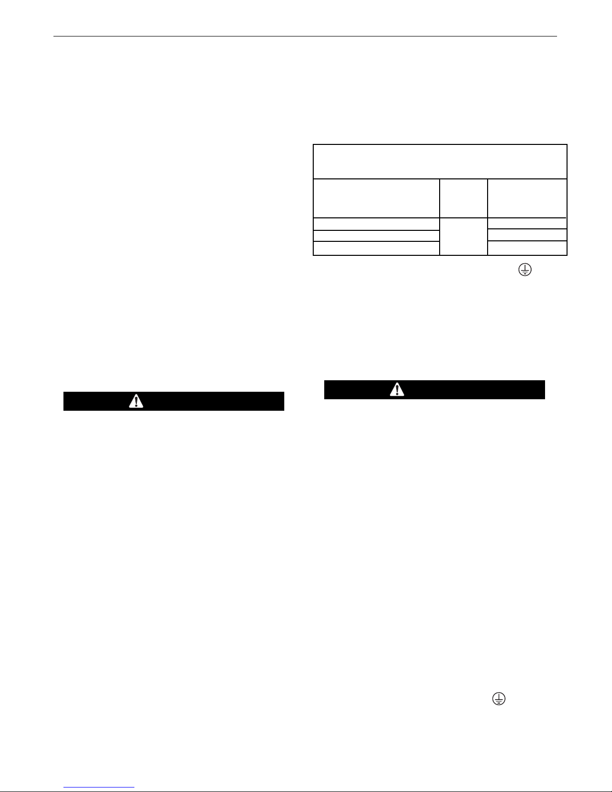
TABLE A.1 Combined Length of Electrode and
Work Cables.
TOTAL COMBINED LENGTH OF
ELECTRODE AND WORK CABLES
Cable Parallel
Length Cables
Lengths up to 150 ft. (46m)
150 ft. (46m) to 200 ft. (61m) 2
200 ft. (61m) to 250 ft. (76m)
Cable Size for
600 Amps
00% Duty Cycle
1
1/0 AWG (53mm
2/0 AWG (67mm
3/0 AWG(85mm
MACHINE GROUNDING
Because this portable engine driven welder creates its
own power, it is not necessary to connect its frame to
an earth ground, unless the machine is connected to
premises wiring (home, shop, etc.).
To prevent dangerous electric shock, other equipment
to which this engine driven welder supplies power
must:
2)
2)
2)
CAUTION
An incorrect arrestor may lead to damage to the
engine or adversely affect performance.
------------------------------------------------------------------------
AIR CLEANER INLET HOOD
Remove the plastic plug covering the air cleaner inlet.
Install the air cleaner inlet hood to the air cleaner.
WELDING TERMINALS
The DUAL VANTAGE®700 is equipped with a toggle
switch for selecting "hot" welding terminals when in
the "WELD TERMINALS ON" position or "cold" welding termi n a l s wh e n in the "REMOT E L Y CO N TROLLED" position.
WELDING OUTPUT CABLES
With the engine off, route the electrode and work
cables thru the strain relief bracket provided on the
front of the base and connect to the terminals provided. These connections should be checked periodically
and tightened if necessary.
WARNING
• Be grounded to the frame of the welder using a
grounded type plug or be double insulated.
• Do not ground the machine to a pipe that carries
explosive or combustible material.
------------------------------------------------------------------------
When this welder is mounted on a truck or trailer, its
frame must be securely connected to the metal frame
of the vehicle. When this engine driven welder is connected to premises wiring such as that in a home or
shop, its frame must be connected to the system earth
ground. See further connection instructions in the section entitled “Standby Power Connections” as well as
the a r ticle o n groun d i n g in the la test Na tional
Electrical Code and the local codes.
In general, if the machine is to be grounded, it should
be connected with a #8 or larger copper wire to a
solid earth ground such as a metal ground stake
going into the ground for at least 10 Feet or to the
metal framework of a building which has been effectively grounded.
The National Electric Code lists a number of alternate
means of grounding electrical equipment. A machine
grounding stud marked with the symbol is provided
on the front of the welder.
A-5

INSTALLATIONDUAL VANTAGE®700
REMOTE CONTROL
The DUAL VANTAGE®700 is equipped with a 6-pin
and a 14-pin connector. The 6-pin connector is for
onnecting the K857 or K857-1 Remote Control or for
c
TIG welding, the K870 foot Amptrol or the K963-3
and Amptrol. When in the CC-STICK, ARC GOUG-
h
ING or CV-WIRE modes and when a remote control is
connected to the 6-pin Connector, the auto-sensing
circuit automatically switches the OUTPUT control
from control at the welder to remote control.
When in TOUCH START TIG mode and when a
Amptrol is connected to the 6-Pin Connector, the
OUTPUT dial is used to set the maximum current
range of the CURRENT CONTROL of the Amptrol.
When in the DOWNHILL PIPE mode and when a
remote control is connected to the 6-Pin or 14-Pin
connector, the output control is used to set the maximum current range of the remote.
EXAMPLE: When the OUTPUT CONTROL on the
welder is set to 200 amps the current range on the
remote control will be 40-200 amps, rather than the
full 40-300 amps. Any current range that is less than
the full range provides finer current resolution for more
fine tuning of the output.
In the CV-WIRE mode, if the feeder being used has a
voltage control when the wire feeder control cable is
connected to the 14-Pin Connector, the auto-sensing
circuit automatically makes OUTPUT CONTROL inactive a nd the wire fe eder vo ltag e contr ol activ e.
Otherwise, the OUTPUT CONTROL is used to preset
the voltage.
The 14-pin connector is used to directly connect a
wire feeder control cable. In the CV-WIRE mode,
when the control cable is connected to the 14-pin connector, the auto-sensing circuit automatically makes
the Output Control inactive and the wire feeder voltage control active.
WARNING
NOTE: When a wire feeder with a built in welding voltage control is connected to the 14-pin
connector, do not connect anything to the 6-pin
connector.
------------------------------------------------------------------------
AUXILIARY POWER RECEPTACLES
Start the engine and set the “IDLER” control switch to the
“High Idle” mode. Voltage is now correct at the receptacles for auxiliary power. This must be done before a
tripped GFCI can be reset properly. See the MAINTENANCE section for more detailed information on testing
and resetting the GFCI.
The auxiliary power of the DUAL VANTAGE® 700 consists of two 20 Amp-120 VAC (5-20R) duplex with
GFCI protection, one 50 Amp 120/240 VAC (14-50R)
receptacle and one 50 Amp 240VAC Three-Phase
(15-50R) receptacle.
The auxiliary power ca p a city is 12,000 Watts
Continuous of 60 Hz, single phase power. The auxiliary power capacity rating in watts is equivalent to voltamperes at unity power factor. The max permissible
current of the 240 VAC output is 50 amps.
The 240 VAC output can be split to provide two separate 120 VAC outputs with a max permissible current of
50 Amps per output to two separate 120 VAC branch
circuits (these circuits cannot be paralleled). Output voltage is within ± 10% at all loads up to rated capacity.
The Three-Phases auxiliary power capacity is 20,000
watts continuous. The maximum current is 48 amps.
120 V DUPLEX RECEPTACLE AND GFCI
A GFCI protects the two 120V auxiliary power.
A GFCI (Ground Fault Circuit Interrupter) is a device to
protect against electric shock should a piece of defective
equipment connected to it develop a ground fault. If this
situation should occur, the GFCI will trip, removing voltage from the output of the receptacle. If a GFCI is tripped
see the MAINTENANCE section for detailed information
on testing and resetting it. A GFCI should be properly
tested at least once every month.
The 120 V auxiliary power receptacles should only be
used with three wire grounded type plugs or approved
double insulated tools with two wire plugs. The current rating of any plug used with the system must be at least
equal to the current capacity of the associated receptacle.
NOTE: The 240 V receptacle has two 120 V circuits, but
are of opposite polarities and cannot be paralleled.
All auxiliary power is protected by circuit breakers. The
120V has 20 Amp circuit breakers for each duplex receptacle. The 120/240V Single Phase and the 240V ThreePhases have a 50 Amp 3-pole Circuit Breaker that disconnects both hot leads and all Three Phases simultaneously.
A-6
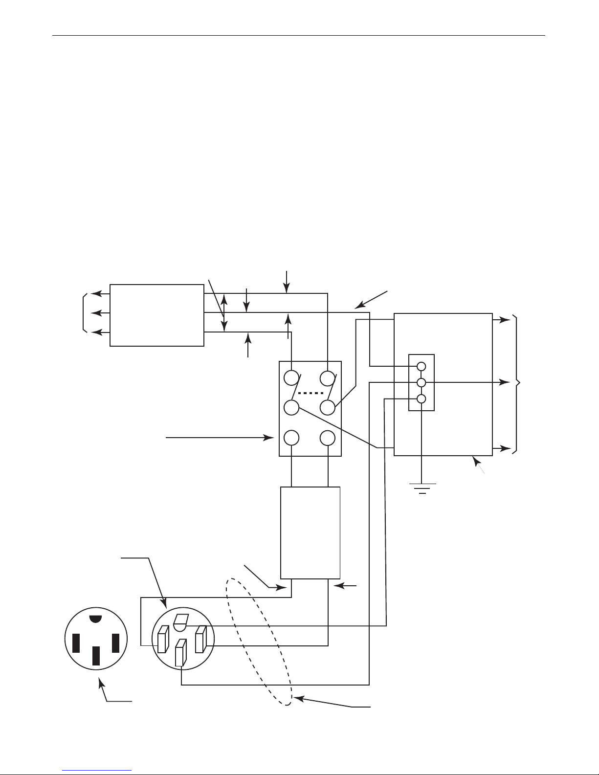
STANDBY POWER CONNECTIONS
60 Hz.
3-Wire
POWER
COMPANY
METER
240 VOLT
120 VOLT
120 VOLT
LOAD
N
NEUTRAL
BUS
GROUND
PREMISES
DISCONNECT AND
SERVICE
OVERCURRENT
PROTECTION
GND
N
NOTE: No. 6 COPPER CONDUCTOR CABLE SEE
NATIONAL ELECTRICAL CODE FOR ALTERNATE WIRE
SIZE RECOMMENDATIONS.
240 VOLT
GROUNDED CONDUCTOR
50AMP
240 VOLT
DOUBLE
POLE
CIRCUIT
BREAKER
DOUBLE POLE DOUBLE THROW
SWITCH RATING TO BE THE SAME
AS OR GREATER THAN PREMISES
SERVICE OVERCURRENT
PROTECTION.
50 AMP, 120/240
VOLT PLUG
NEMA TYPE 14-50
50 AMP, 120/240 VOLT
RECEPTACLE
INSTALLATIONDUAL VANTAGE®700
The DUAL VANTAGE®700 is suitable for temporary, standby or
emergency power using the engine manufacturer’s recommended
maintenance schedule.
The DUAL VANTAGE®700 can be permanently installed as a
standby power unit for 240 volt-3 wire, 50 amp service.
Connections must be made by a licensed electrician who can
determine how the 120/240 VAC power can be adapted to the
particular installation and comply with all applicable electrical
codes. Refer to the connection diagram shown in Figure A.4.
1. Install the double-pole, double-throw switch between the power
company meter and the premises disconnect. Switch rating
must be the same or greater than the customer’s premises disconnect and service over current protection.
FIGURE A.4 Connection of the DUAL VANTAGE® 700 to Premises Wiring
2. Take necessary steps to assure load is limited to the capacity of
the DUAL VANTAGE®700 by installing a 50 amp, 240 VAC double pole circuit breaker. Maximum rated load for each leg of the
240 VAC auxiliary is 50 amps. Loading above the rated output
will reduce output voltage below the allowable -10% of rated
voltage which may damage appliances or other motor-driven
quipment and may result in overheating of the
e
DUAL VANTAGE
®
700 engine and / or alternate windings.
3. Install a 50 amp 120/240 VAC plug (NEMA Type 14-50P) to the
double-pole circuit breaker using No. 6, 4 conductor cable of
the desired length.
4. Plug this cable into the 50 Amp 120/240 Volt receptacle on the
DUAL VANTAGE®700 case front.
A-7
INSTALLATIONDUAL VANTAGE®700
ENG INE WE LDER
K1797-xx
CABLE
K1797-xx
CABLE
WIRE FEEDER
A
Operator
A
Operator B
WIRE FEEDER B
S
et Mode
t
o CV Wire
S
et Mode
to CV Wire
Set Weld
Terminals
to Remote
Set Weld
T
erminals
to Remote
S
et Polarity
to Match
Electrode
P
olarity
Set Polarity
to Match
E
lectrode
Polarity
Set to
42V
Set to
42V
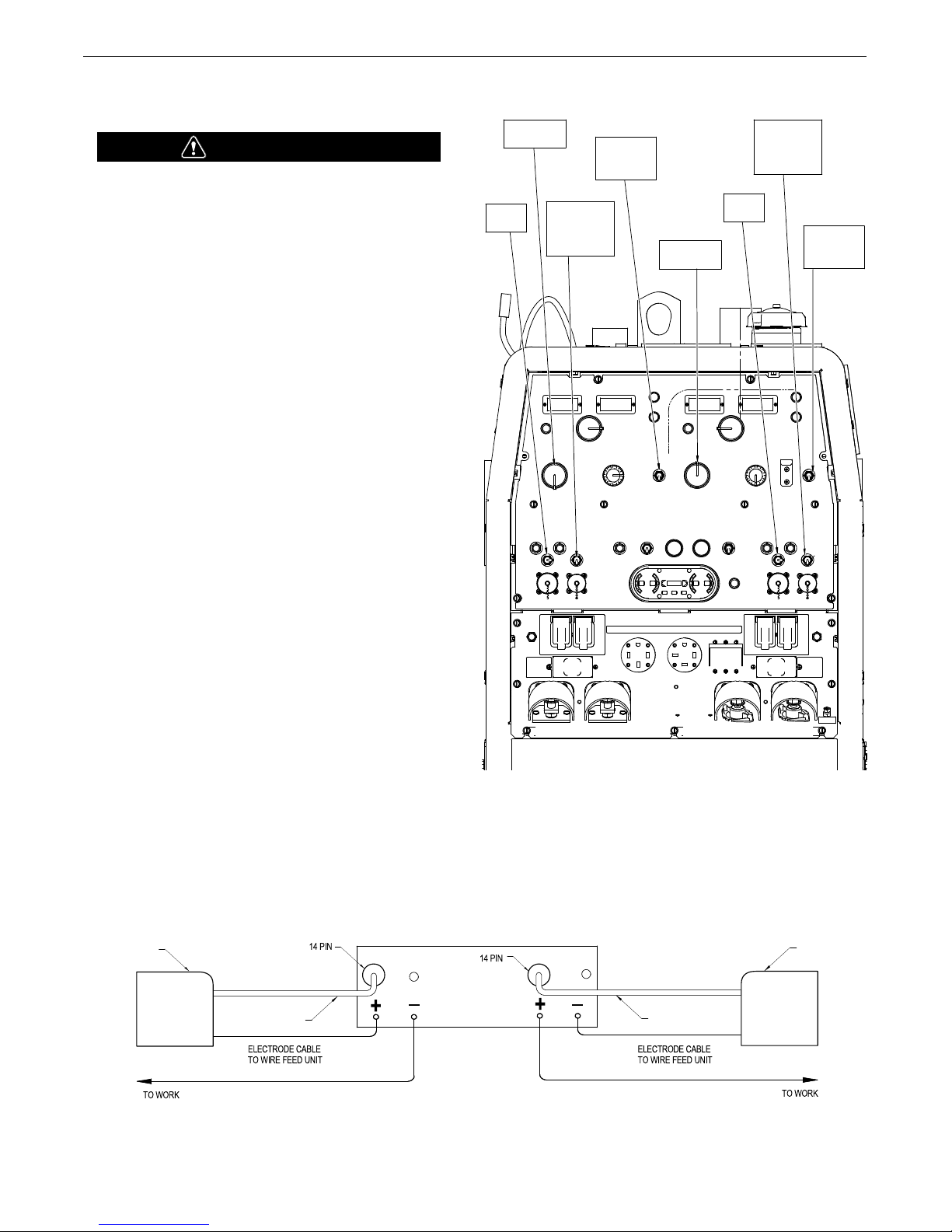
CONNECTION OF WIRE FEEDERS WITH CONTROL
CABLE (14 PIN)
WARNING
Shut off welder before making any electrical connections.
------------------------------------------------------------------
CONNECTION OF LF-72, LF-74, FLEX FEED 74 HT,
FLEX FEED 84, LN-25 PRO DUAL POWER TO THE
DUAL VANTAGE
Note: The DUAL VANTAGE®700 can operate two different
wire feeders at the same time.
• Shut the welder off.
• Set the “WIRE FEEDER VOLTMETER” switch to either “+” or “-”
as required by the electrode being used (See Figure A.2).
• For electrode Positive, connect the electrode cable to the "+" terminal of the welder and work cable to the "-" terminal of the welder.
For electrode Negative, connect the electrode cable "-" terminal of
the welder and work cable to the "+" terminal of the welder.
®
700
FIGURE A.2
• Set the “MODE” switch to the “CV-WIRE” position.
• Adjust the “ARC CONTROL” knob to desired Crispness. SOFT for
MIG and CRISP for Innershield.
• Set the “WE LDING T ERMINALS ” switch to the “REMOTE
CONTROLLED” position.
• Set the wire feeder voltage switch to 42V.
• Connect the 14 pin control cable from the wire feeder to the
engine drive (See Figure A.3).
• This procedure can be done for both “Single” and “Dual”
operator modes.
FIGURE A.3
A-8
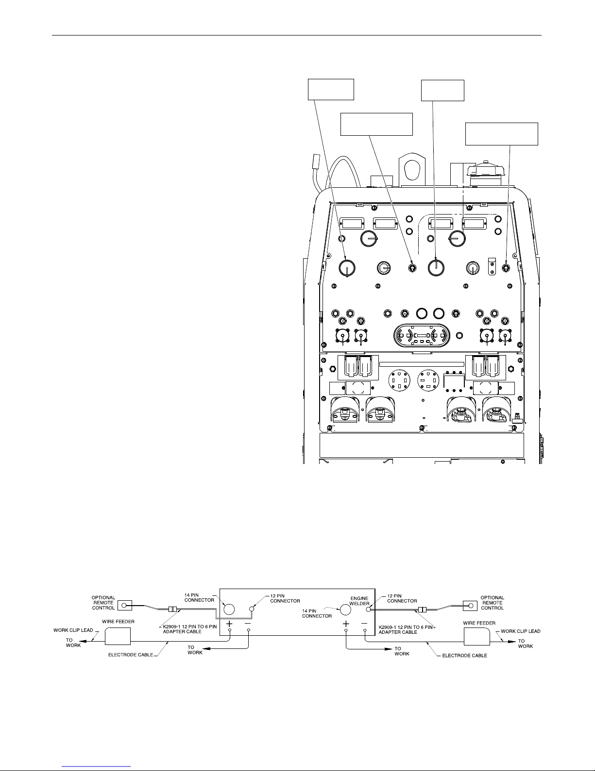
CONNECTION OF ACROSS THE ARC WIRE FEEDERS
Set Mode
to CV Wire
Set Mode
t
o CV Wire
S
et Weld Terminals
to “On”
S
et Weld Terminals
to “On”
ENGI NE WE LDER
Operator A
Operator B
TO THE DUAL VANTAGE
hese connections instructions apply to both the LN-25 Pro and
T
Activ8 models. The feeders have an internal contactor and the
lectrode is not energized until the gun trigger is closed. When the
e
gun trigger is closed the wire will begin to feed and the welding
process is started.
• Shut the welder off.
• For electrode Positive, connect the electrode cable to the "+"
terminal of the welder and work cable to the "-" terminal of the
welder. For electrode Negative, connect the electrode cable "-"
terminal of the welder and work cable to the "+" terminal of the
welder.
• Attach the single lead from the front of the feeder to work using
the spring clip at the end of the lead. This is a control lead to
supply current to the wire feeder motor; it does not carry welding current (See Figure A.5).
• Set the MODE switch to the "CV-WIRE" position (See Figure A.4).
®
700
IGURE A.4
F
INSTALLATIONDUAL VANTAGE®700
• Set the "WELD TERMINALS" switch to "ON"
• Set the "ARC CONTROL" knob to "0" initially and adjust to suit.
NOTE: The LN-25 (K431) Remote Control Module and (K432)
Remote Control Module are not recommended for use with
®
the DUAL VANTAGE
700.
FIGURE A.5
A-9

CAUTION
ertain electrical devices cannot be powered by this product. See Table A.2
C
TABLE A.2
ELECTRICAL DEVICE USE WITH THIS PRODUCT
INSTALLATIONDUAL VANTAGE®700
Type
Resistive
Capacitive
Inductive
Common Electrical Devices
Heaters, toasters, incandescent
light bulbs, electric range, hot
pan, skillet, coffee maker.
TV sets, radios, microwaves,
appliances with electrical control.
Single-phase induction motors,
drills, well pumps, grinders, small
refrigerators, weed and hedge
trimmers.
Possible Concerns
NONE
Voltage spikes or high voltage
regulation can cause the capacitative elements to fail. Surge
protection, transient protection, and
additional loading is recommended for 100% fail-safe operation. DO NOT RUN
THESE DEVICES WITHOUT
ADDITIONAL RESISTIVE TYPE
LOADS.
These devices require large
current inrush for starting.
Some synchronous motors may
be frequency sensitive to attain
maximum output torque, but
they SHOULD BE SAFE from
any frequency induced failures.
Capacitive / Inductive
The Lincoln Electric Company is not responsible for any damage to electrical components
improperly connected to this product.
Computers, high resolution TV sets,
complicated electrical equipment.
A-10
An inductive type line conditioner along with transient and
surge protection is required,
and liabilities still exist.
DO NOT USE THESE DEVICES
WITH THIS PRODUCT.
OPERATION
SAFETY PRECAUTIONS
ead and understand this entire section before
R
operating your DUAL VANTAGE
• Do not attempt to use this equipment until you
WARNING
have thoroughly read the engine manufacturer’s
manual supplied with your welder. It
includes important safety precautions,
detailed engine starting, operating and
maintenance instructions, and parts
lists.
---------------------------------------------------------
---------------ELECTRIC SHOCK can kill.
• Do not touch electrically live parts or electrode
with skin or wet clothing.
• Insulate yourself from work and ground
• Always wear dry insulating gloves.
-----------------------------------------------------------
---------------
ENGINE EXHAUST can kill.
• Use in open, well ventilated areas or
vent exhaust outside
• Do not stack anything near the engine.
------------------------------------------------------------------------
MOVING PARTS can injure.
• Do not operate with doors open or guards off.
• Stop engine before servicing.
• Keep away from moving parts
--------------------------------------------------------------------------
•
Only qualified personnel should operate this
equipment.
®
700.
OPERATIONDUAL VANTAGE®700
The
DUAL VANTAGE®700
VRD(Voltage Reduction Device). The VRD operates
in the CC-Stick mode reducing the OCV to <13 volts,
increasing operator s afety when welding is per-
ormed in environments with increased hazard of
f
electric shock such as wet areas and hot, humid
sweaty conditions.
is fitted with a selectable
FOR AUXILIARY POWER:
Start the engine and set the IDLER control switch to
the desired operating mode. Full power is available
regardless of the welding control settings providing no
welding current is being drawn.
ENGINE OPERATION
Before Starting the Engine:
• Be sure the machine is on a level surface.
• Open side engine door and remove the engine oil
dipstick and wipe it with a clean cloth. Reinsert the
dipstick and check the level on the dipstick.
• Add oil (if necessary) to bring the level up to the full
mark. Do not overfill. Close engine door.
• Check radiator for proper coolant level. (Fill if necessary).
• See Engine Owner’s Manual for specific oil and
coolant recommendations.
•
Always operate the welder with the sliding door
closed and the side panels in place as these provide maximum protection from moving parts and
insure proper cooling air flow.
--------------------------------------------------------------------------
GENERAL DESCRIPTION
The D U AL VANTAGE®700 i s a dual-o p e r a tor
multi-purpose diesel engine-driven welding power
source. The machine uses a brush type alternating current generator for DC multi-purpose welding, for 240
VAC single phase. The DC welding control system uses
state of the art Chopper Technology for superior
welding performance.
B-1
WARNING
HAND PRIMER BUTTON
ADD FUEL
• Stop engine while fueling.
• Do not smoke when fueling.
• Kee p s parks and flame away
rom tank.
f
• Do not leave unattended while
fueling.
D I E S E L
FUEL
can cause fire.
DIESEL FUEL ONLY-Low sulphur fuel or ultra low
sulphur fuel in U.S.A. and Canada.
-----------------------------------------------------------------------
• Remove the fuel tank cap.
• Fill the tank. DO NOT FILL THE TANK TO THE
POINT OF OVERFLOW.
• Replace the fuel cap and tighten securely.
• See Engine Owner’s Manual for specific fuel recommendations.
• Wipe up spilled fuel and allow
fumes to clear before starting
engine.
• Do not overfill tank, fuel expansion may cause overflow.
OPERATIONDUAL VANTAGE®700
BREAK-IN PERIOD
No brea k in period is require d for the Cummins
engine.
RECOMMENDED APPLICATIONS
The
DUAL VANTAGE®700
current DC welding output for stick (SMAW) and TIG
welding. The DUAL VANTAGE®700 also provides
excellent constant voltage DC welding output for MIG
(GMAW), Innershield (FCAW), Outershield (FCAW-G)
and Me t a l Core we l d i ng. In ad d i t ion the
DUAL VANTAGE®700 can be used for Arc Gouging
with carbons up to 1/2”(13mm) in diameter.
The DUAL VANTAGE®700 is not recommended for
pipe thawing.
provides excellent constant
GENERATOR
The
DUAL VANTAGE®700
single phase and 415V three phase output for auxiliary
power and emergency standby power.
provides smooth 240 VAC
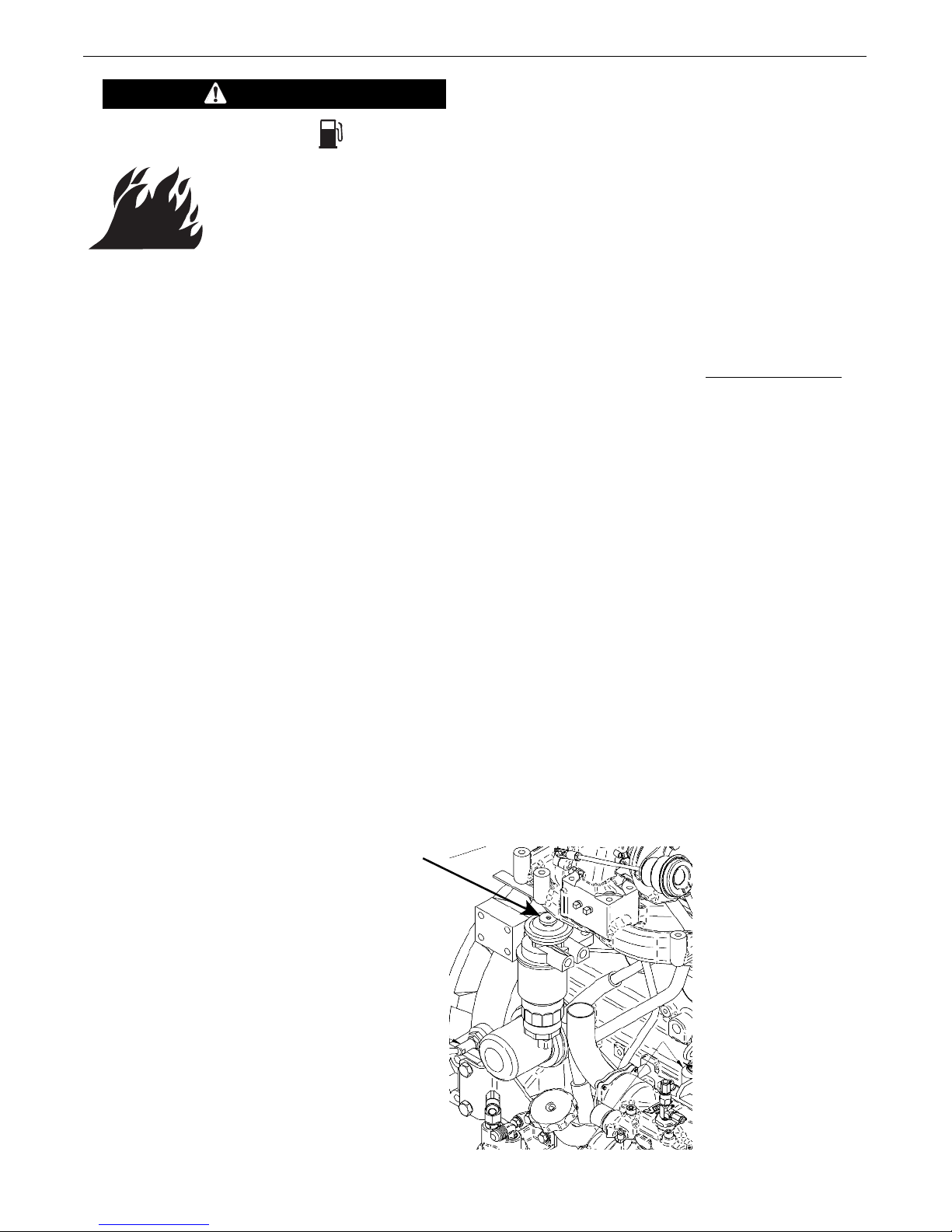
HAND PRIMER BUTTON
Air in the fuel system will cause the following engine
problems:
• Hard to start
• Run rough
• Misfire
• Fuel knock
For faster air purge, a small amount of air can be
vented from the system by pumping the hand primer
button on the fuel filter head. (See Figure B.1,
Engine Service Side View)
FIGURE B.1 Engine Service Side View
B-2
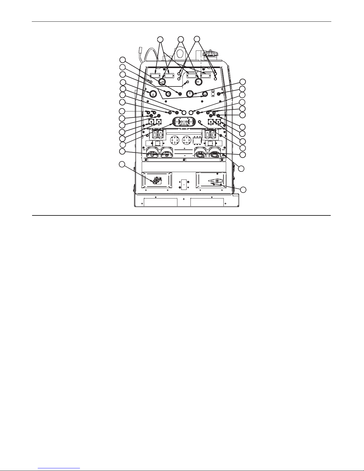
FIGURE B.2
1
2
3
3
4
5
5
6
7
8
8
8A
8A
9
7
9
10
1
0
1
1
12
13
1
4
15
1
6
17
18
1
9
1
1
2
2
21
20
1
2
3
3
4
5
5
7
8
8
8A
8A
9
7
9
10
1
0
1
1
12
13
1
4
15
1
1
AV
+– +–
OPERATIONDUAL VANTAGE®700
WELDING CONTROLS (Figure B.2)
1. OUTPUT CONTROL- The OUTPUT dial is
used to preset the output voltage or current as displayed on the digital meters for the five welding
modes. When in the ARC GOUGING or CV-WIRE
modes and when a remote control is connected to
the 6-Pin or 14-Pin Connector, the auto-sensing circuit automatically switches the OUTPUT CONTROL
from control at the welder to the remote control.
When in the TOUCH START TIG mode and when
an Amptrol is connected to the 6-Pin Connector,
the OUTPUT dial is used to set the maximum current range of the CURRENT CONTROL of the
Amptrol.
2.
DIGITA L OUT P UT METERS-
The di g ital
meters allow the output voltage (CV-WIRE mode)
or current (CC-STICK, DOWNHILL PIPE, ARC
GOUGING and TIG modes) to be set prior to weld-
When in DOWNHILL PIPE and CC-STICK modes if
a remote control is connected to the 6-Pin or 14 Pin
Connectors, the output is controlled by the remote
and the output control on the machine is used to set
the maximum current range for the remote.
EXAMPLE: When the OUTPUT CONTROL on the
welder is set to 200 amps the current range on the
remote control will be MIN-200 amps, rather than the
full MIN-MAX amps. Any current range that is less than
the full range provides finer current resolution for more
fine tuning of the output.
In the CV-WIRE mode, if the feeder being used has
a voltage control when the wire feeder control cable
is connected to the 14-Pin Connector, the autosensing circuit automatically makes OUTPUT CONTROL inactive and the wire feeder voltage control
active. Otherwise, the OUTPUT CONTROL is used
to preset the voltage
ing using the OUTPUT control dial. During welding,
the m e t e r dis p l a y the a c t ual ou t p u t volt a g e
(VOLTS) and current (AMPS). A memory feature
holds the display of both meters on for seven seconds after welding is stopped. This allows the operator to read the actual current and voltage just prior
to when welding was ceased.
While the display is being held the left-most decimal point in each display will be flashing. The
accuracy of the meters is +/- 3%.
3. WELD MODE SELECTOR SWITCH-
(Provides five selectable welding modes)
CV-WIRE
ARC GOUGING
DOWNHILL PIPE
CC-STICK
TOUCH START TIG
B-3
4. ARC CONTROL- The ARC CONTROL dial is active in
the CV-WIRE, CC-STICK and DOWNHILL PIPE modes,
and has different functions in these modes. This control is
not active in the TIG and ARC GOUGING mode.
C-STICK mode: In this mode, the ARC CONTROL dial
C
sets the short circuit current (arc-force) during stick welding to adjust for a soft or crisp arc. Increasing the dial from
–10 (soft) to +10 (crisp) increases the short circuit current
and prevents sticking of the electrode to the plate while
welding. This can also increase spatter. It is recommended that the ARC CONTROL be set to the minimum number
without electrode sticking. Start with a setting at 0.
DOWNHILL PIPE mode: In this mode, the ARC CONTROL dial sets the short circuit current (arc-force) during
stick welding to adjust for a soft or a more forceful digging
arc (crisp). Increasing the number from –10 (soft) to +10
(crisp) increases the short circuit current which results in a
more forceful digging arc. Typically a forceful digging arc is
preferred for root and hot passes. A softer arc is preferred
for fill and cap passes where weld puddle control and deposition ("stacking" of iron) are key to fast travel speeds. It is
recommended that the ARC CONTROL be set initially at 0.
OPERATIONDUAL VANTAGE®700
10. WELD TERMINALS CONTROL SWITCH-
In the WELD TERMINALS ON position, the output is
electrically hot all the time. In the REMOTELY CONTROLLED position, the output is controlled by a wire
feeder or amptrol device, and is electrically off until a
emote switch is depressed.
r
11. WIRE FEEDER VOLTMETER SWITCH:
Matches the polarity of the wire feeder voltmeter to the
polarity of the electrode.
12. VRD (Vo lt ag e Red u c ti on Device)
INDICATOR LIGHTS- On the front panel of the
DUAL VANTAGE®700
light when lit indicates OCV(Open Circuit Voltage) is
equal to or
greater than 30V and a green light when lit
indicates OCV(Open Circuit Voltage) is less than 30V.
The VRD “On/Off” switch inside the control panel must
be “On” for the VRD function to be active and the lights
to be enabled. When the machine is first started with
VRD enabled, both lights will illuminate for 5 seconds.
are two indicator lights. A red
CV-WIRE mode: In this mode, turning the ARC CONTROL
clock wise from –10 (soft) to +10 (crisp) changes the arc
from soft and washed-in to crisp and narrow. It acts as an
inductance/pinch control. The proper setting depends on
the procedure and operator preference. Start with a setting
of 0.
5. WELD OUTPUT TERMINALS WITH FLANGE
NUT- Provides a connection point for the electrode and
work cables.
6. GROUND STUD- Provides a connection point for
connecting the machine case to earth ground.
7. 14-PIN CONNECTOR- For attaching wire feeder con-
trol cables. Includes contactor closure circuit, auto-sensing
remote control circuit, and 42V power. The remote control
circuit operates the same as the 6 Pin Amphenol.
8. 42V / 115V W I RE FEEDER V OLTAGE
SWITCH:
Toggles output of 14-pin connector to voltage requirement of Wire Feeder. (Located above 14-pin connector.)
8A. 42V and 115V WIRE FEEDER BREAKERS
9. 6-PIN CONNECTOR-
control equipment. Includes auto-sensing remote control
circuit.
For attaching optional remote
These lights monitor the OCV(Open Circuit Voltage) and
weld voltage at all times. In the CC-Stick mode when
not welding the green light will illuminate indicating that
the VRD has reduced the OCV to less than 30V. During
welding the red light will illuminate whenever the arc
voltage is equal to or greater than 30V. This means that
the red and green light may alternate depending on the
weld voltage. This is normal operation.
If the red light remains illuminated when not welding in
the CC-stick mode, the VRD is not functioning properly.
Please refer to your local field service shop for service.
If the VRD is turned “On” and the lights don’t come
“On”, refer to the trouble shooting section.
TABLE B.1
MODE VRD "ON" VRD "OFF"
CC-STICK OCV Green (OCV Reduced)
CV-WIRE OCV Green (OCV Reduced)
PIPE OCV Green (No Output)
ARC GOUGING
TIG OCV Green (Process is Low Voltage)
While Red or Green
Welding (Depends on Weld Voltage) *
While Red or Green
Welding (Depends on Weld Voltage) *
While Not Applicable (No Output)
Welding
OCV Green (OCV Reduced)
While (Depends on Weld Voltage) *
Welding
While Green (Process is Low Voltage)
Welding
VRD INDICATOR LIGHTS
Green (No OCV)
Weld Terminals Remotely Controlled
Gun Trigger Open No Lights
* It is normal for the lights to alternate between colors while welding.
B-4

OPERATIONDUAL VANTAGE®700
ENGINE CONTROLS:
13. RUN/STOP SWITCH -
-RUN position energizes the engine prior to starting. STOP position stops the engine. The oil pressure interlock switch prevents battery drain if the
switch is left in the RUN position and the engine is
not operating.
14. GLOW PLUG PUSH BUTTON -
• When pushed activates the glow plugs. Glow plug
should not be activated for more than 20 seconds
continuously.
15. CIRCUIT B R E A K E R- For pro tecti on o f
Battery Charging Circuit.
16. START PUSH BUTTON / ENGINE STOP
BUTTON - Energizes the starter motor to crank
the engine. Shuts down engine.
17. IDLER SWITCH- Has two positions as follows:
1) In the HIGH position, the engine runs at the high
idle speed controlled by the engine governor.
2) In the AUTO position, the idler operates as follows:
• When switched from HIGH to AUTO or after
starting the engine, the engine will operate at full
speed for approximately 12 seconds and then go
to low idle speed.
• When the electrode touches the work or power is
drawn for lights or tools (approximately 100
Watts minimum), the engine accelerates and
operates at full speed.
• When welding ceases or the AC power load is
turned off, a fixed time delay of approximately 12
seconds starts. If the welding or AC power load
is not restarted before the end of the time delay,
the idler reduces the engine speed to low idle
speed.
• The engine will automatically return to high idle
speed when there is welding load or AC power
load reapplied.
18. DASH BOARD GAUGE -
The dash board gauge displays 5 gauges:
3a. OIL PRESSURE
The gauge displays the engine oil pressure
when the engine is running.
3b. ENGINE TEMPERATURE
The gauge displays the engine coolant tem-
perature.
3c. HOUR METER
The hour meter displays the total time that the
engine has been running. This meter is a useful indicator for scheduling preventive maintenance.
3d. FUEL LEVEL
Displays the level of diesel fuel in the fuel
tank.
The operator must watch the fuel level closely
to prevent running out of fuel and possibly
having to bleed the system.
3e. BATTERY VOLTAGE INDICATOR
Displays the battery voltage and indicates that
the charging system is functioning properly.
19. ENGINE PROTECTION LIGHT- A warning
indicator light for Low Oil Pressure and/or Coolant
Over Temperature.The light is off when the systems
are functioning properly. The light will come on and
the engine will shutdown when there is Low Oil
Pressure and/or the Coolant is Over Temperature.
Note: The light remains off when the RUN-STOP
switch is in the "ON" position prior to starting the
engine. However if the engine is not started within 60
seconds the light will come on. When this happens the
RUN-STOP switch must be returned to the "OFF" position to reset the engine protection system and light.
20. BATTERY DISCONNECT SWITCH -
Batte r y disconnect s w itch provi d e s
lockout/tagout capability. Switch is conveniently
located on the front bottom of the machine.
21. THERMAL LIGHTS
indicate the Power Source has been driven into
thermal overload. Welding output shuts off to
protect the welding system components and
resets when the overload condition is resolved.
The Engine will continue to operate.
- These st atus light s
22. SINGLE / DUAL OPERATOR SELECTOR
-
B-5
SWITCH
Parallel switch that allows the user to choose
between Single Operator and Dual Operator weld
modes. Single Operator mode is when the switch
is in the “Up” position. Dual Operator mode is
when the switch is in the “Down” position.

OPERATIONDUAL VANTAGE®700
ENGINE OPERATION
STARTING THE ENGINE
1. Open the engine compartment door and check that
he fuel shutoff valve located to the left of the fuel
t
filter housing is in the open position (lever to be in
ine with the hose).
l
2. Make sure battery disconnect switch is in the on
position.
3. Check for proper oil level and coolant level. Close
engine compartment door.
4. Remove all plugs c onn ected to the AC p owe r
receptacles.
5. Set IDLER switch to “AUTO”.
6. Firmly set the Operator Selector Switch to Single or
Dual. The Operator Selector Switch can be set to
Single or Dual mode and must be securely in one of
the two positions.
7. Set the RUN/STOP switch to “RUN”. Observe that
the engine protection and battery charging lights
are on.
Press Glow Plug Button and hold 15 to 20 seconds.
7a.
8.
Press START button until the engine starts or for up to 10
seconds.
9. Release the engine START button when the engine
starts.
10. Check that the engine protection and battery
charging lights are off. If the engine protection light
is on after starting, the engine will shutdown in a
few seconds. Investigate any indicated problem.
11. Allow the engine to warm up at low idle speed for
several minutes before applying a load and/or
switching to high idle. Allow a longer warm up time
in cold weather.
STOPPING THE ENGINE
1. Switch the RUN/STOP switch to “STOP”. This turns
off the voltage supplied to the shutdown solenoid. A
ackup shutdown can be accomplished by shutting
b
off the fuel valve located on the fuel line.
TYPICAL FUEL CONSUMPTION
Refer to Table B.2 for typical fuel consumption of the
DUAL VANTAGE®700 Engine for various operating
settings.
Table B.2
Cummins B3.3T Engine Fuel Consumption
Cummins B3.3T Running Time for
69HP 25GAL.(94.6L)
(Hours)
High Idle No load 1.10 Gal./hour 22.7
1860 RPM (4.17 L/hour)
Low Idle No load 0.72 Gal./hour 34.83
1500 RPM (2.72 L/hour)
DC CC Weld Output 2.37 Gal./hour 10.56
500A 100% Duty Cycle
DC CC Weld Output 2.92 Gal./hour 8.56
600A 100% Duty Cycle
DC CC Weld Output 2.08 Gal./hour 12.02
650A 60% Duty Cycle
DC CC Weld Output 1.70 Gal./hour 14.71
700A 40% Duty Cycle
Aux. 7.2kva 1.28 Gal./hour 19.55
(4.84 L/hour)
Aux. 12kva 1.63 Gal./hour 15.3
(6.18 L/hour)
Aux. 20kva 2.18 Gal./hour 11.48
(8.25 L/hour)
(8.96 L/hour)
(11.06 L/hour)
(7.87 L/hour)
(6.43 L/hour)
COLD WEATHER STARTING
With a fully charged battery and the proper weight oil,
the engine should start satisfactorily even down to
about 0°F(-18°C). If the engine must be frequently
started below 10°(-12°C), it may be desirable to install
the optional ether start kit (K887-1). For extreme cold
conditions it may be desirable to install additional
equipment such as a block heater or oil pan pad
heater, etcetera.
NOTE: Extreme cold weather starting may require
longer glow plug operations.
NOTE: This data is for reference only. Fuel consumption is
approximate and can be influenced by many factors, including engine maintenance, environmental conditions and fuel
quality.
B-6

OPERATIONDUAL VANTAGE®700
WELDER OPERATION
UTY CYCLE
D
Duty Cycle is the percentage of time the load is being
applied in a 10 minute period. For example a 60% duty
cycle, represents 6 minutes of load and 4 minutes of no
oad in a 10 minute period.
l
ELECTRODE INFORMATION
For any electrode the procedures should be kept within the rating of the machine. For information on electrodes and their proper application see (www.lincolnelectric.com) or the appropriate Lincoln publication.
The
DUAL VANTAGE®700
range of DC stick electrodes. The MODE switch provides
two stick welding settings as follows:
CONSTANT CURRENT (CC-STICK)
WELDING
The CC-STICK position of the MODE switch is designed
for horizontal and vertical-up welding with all types of
electrodes, especially low hydrogen.
The ARC CONTROL dial sets the short circuit current (arcforce) during stick welding to adjust for a soft or crisp arc.
Increasing the number from -10(soft) to +10(crisp) increases the short circuit current and prevents sticking of the
electrode to the plate while welding. This can also increase
spatter. It is recommended that the ARC CONTROL be set
to the minimum number without electrode sticking. Start
with the dial set at 0.
NOTE: Due to the low OCV with the VRD on, a very
slight delay during striking of the electrodes may
occur. Due to the requirement of the resistance in the
circuit to be low for a VRD to operate, a good metalto-metal contact must be made between the metal
core of the electrode and the job. A poor connection
anywhere in the welding output circuit may limit the
operation of the VRD. This includes a good connection of the work clamp to the job. The work clamp
should be connected as close as practical to where
the welding will be performed.
can be used with a broad
B. For Re-Striking Electrodes
Some electrodes form a cone at the end of the elec-
rode after the welding arc has been broken, particu-
t
larly iron powder and low hydrogen electrodes. This
one will need to be broken off in order to have the
c
metal core of the electrode make contact.
E6010 - Push, Twist in Joint, Lift
7018, E7024 - Touch, Rock Back and Forth in Joint, Lift.
E
Once the arc is started, normal welding technique for
the application is then used.
For other electrodes the above techniques should be
tried first and varied as needed to suit operator preference. The goal for successful starting is good metal to
metal contact.
For indicator light operation, see Table B.1.
DOWNHILL PIPE Welding
This slope controlled setting is intended for "out-of-position" and "down hill" pipe welding where the operator
would like to control the current level by changing the arc
length.
The ARC CONTROL dial sets the short circuit current
(arc-force) during stick welding to adjust for a soft or
more forceful digging arc (crisp). Increasing the number
from -10(soft) to +10(crisp) increases the short circuit
current which results in a more forceful digging arc.
Typically a forceful digging arc is preferred for root and
hot passes. A softer arc is preferred for fill and cap passes where weld puddle control and deposition (“stacking”
of iron) are key to fast travel speeds. This can also
increase spatter.
It is recommended that the ARC CONTROL be set to the
minimum number without electrode sticking. Start with
the dial set at 0.
NOTE: With the VRD switch in the “ON” position (See
figure A.1 for location) there is no output in the DOWNHILL PIPE mode.
Table B.1.
For indicator light operation, see
A. For New Electrodes
E6010 - Touch, Lift to Start the Arc.
E7018, E7024 - Touch, Rock Back and Forth in Joint, Lift.
Once the arc is started, normal welding technique for
the application is then used.
B-7

OPERATIONDUAL VANTAGE®700
TIG WELDING
The TOUCH START TIG setting of the MODE switch
s for DC TIG (Tungsten Inert Gas) welding. To initiate
i
a weld, the OUTPUT CONTROL dial is first set to the
esired current and the tungsten is touched to the
d
work. During the time the tungsten is touching the
work there is very little voltage or current and, in general, no tungsten contamination. Then, the tungsten is
gently lifted off the work in a rocking motion, which
establishes the arc.
When in the TOUCH START TIG mode and when a
Amptrol is connected to the 6-Pin connector the OUTPUT CONTROL dial is used to set the maximum current range of the current control of the Amptrol.
The ARC CONTROL is not active in the TIG mode. To
STOP a weld, simply pull the TIG torch away from the
work.
When the arc voltage reaches approximately 30 Volts
the arc will go out and the machine will reset the current to the Touch Start level.
To reinitiate the arc, retouch the tungsten to the work
and lift. Alternatively, the weld can be stopped by
releasing the Amptrol or arc start switch.
If desired, the K930-2 TIG Module can be used with
the DUAL VANTAGE®700. The settings are for reference.
DUAL VANTAGE
®
700 settings when using the K930-
2 TIG Module with an Amptrol or Arc Start Switch:
• Set the MODE Switch to the TOUCH START TIG
setting.
• Set the "IDLER" Switch to the "AUTO" position.
• Set the "WELDING TERMINALS" switch to the
"REMOTELY CONTROLLED" position.
This will keep the "Solid State" contactor open and
provide a "cold" electrode until the Amptrol or Arc
Start Switch is pressed.
When using the TIG Module, the OUTPUT CONTROL
®
on the DUAL VANTAGE
700 is used to set the maximum range of the CURRENT CONTROL on the TIG
Module or an Amptrol if connected to the TIG Module.
NOTE: The TIG process is to receive a low voltage
welding process. There is no difference in
operation with the VRD “On” or “Off” for this
mode. For indicator light operation, see Table
B.1.
®
The DUAL VANTAGE
700 an be used in a wide variety of DC TIG welding applications. In general the
‘Touch Start’ feature allows contamination free starting without the use of a Hi-frequency unit.
TYPICAL CURRENT RANGES
Tungsten Electrode DCEN (-) DCEP (+) Approximate Argon Gas Flow TIG TORCH
Diameter in. (mm) Flow Rate C.F.H. ( l /min.) Nozzle Size (4), (5)
1%, 2% Thoriated 1%, 2% Thoriated Aluminum Stainless Steel
Tungsten Tungsten
.010 (.25) 2-15 (3) 3-8 (2-4) 3-8 (2-4) #4, #5, #6
0.020 (.50) 5-20 (3) 5-10 (3-5) 5-10 (3-5)
0.040 (1.0) 15-80 (3) 5-10 (3-5) 5-10 (3-5)
1/16 (1.6) 70-150 10-20 5-10 (3-5) 9-13 (4-6) #5, #6
3/32 (2.4) 150-250 15-30 13-17 (6-8) 11-15 (5-7) #6, #7, #8
1/8 (3.2) 250-400 25-40 15-23 (7-11) 11-15 (5-7)
5/32 (4.0) 400-500 40-55 21-25 (10-12) 13-17 (6-8) #8, #10
3/16 (4.8) 500-750 55-80 23-27 (11-13) 18-22 (8-10)
1/4 (6.4) 750-1000 80-125 28-32 (13-15) 23-27 (11-13)
(1) When used with argon gas. The current ranges shown must be reduced when using argon/helium or pure helium shielding gases.
(2) Tungsten electrodes are classified as follows by the American Welding Society (AWS):
Pure EWP
1% Thoriated EWTh-1
2% Thoriated EWTh-2
Though not yet recognized by the AWS, Ceriated Tungsten is now widely accepted as a substitute for 2% Thoriated Tungsten in AC and DC applications.
(3) DCEP is not commonly used in these sizes.
(4) TIG torch nozzle "sizes" are in multiples of 1/16ths of an inch:
(5) TIG torch nozzles are typically made from alumina ceramic. Special applications may require lava nozzles, which are less prone to breakage, but cannot withstand high temperatures
# 4 = 1/4 in. (6 mm)
# 5 = 5/16 in. (8 mm)
# 6 = 3/8 in. (10 mm)
# 7 = 7/16 in. (11 mm)
# 8 = 1/2 in. (12.5 mm)
#10 = 5/8 in. (16 mm)
and high duty cycles.
TABLE B.3
(1)
FOR TUNGSTEN ELECTRODES
(2)
B-8

OPERATIONDUAL VANTAGE®700
WIRE WELDING-CV
Connect a wire feeder to the DUAL VANTAGE®700
ac cording to the in structi ons in INSTALLA TION
INSTRUCTIONS Section.
®
The DUAL VANTAGE
700 in the CV-WIRE mode,
permits it to be used with a broad range of flux cored
wire (Innershield and Outershield) electrodes and
solid wires for MIG welding (gas metal arc welding).
Welding can be finely tuned using the ARC CONTROL. Turning the ARC CONTROL clockwise from –
10 (soft) to +10 (crisp) changes the arc from soft and
washed-in to crisp and narrow. It acts as an inductance/pinch control. The proper setting depends on
the procedure and operator preference. Start with the
dial set at 0.
ARC GOUGING
The DUAL VANTAGE®700 can be used for arc gouging. The minimum output in the arc gouging mode is
200 Amps. For arc gouging below 200 Amps use the
CC-Stick Mode. For optimal performance, set the
MODE per Table B.4.
PARALLELING
hen paralleling machines in order to combine their
W
outputs, all units must be operated in the CC-STICK
mode only at the same output settings. To achieve
this, turn the WELD MODE switch to the CC-STICK
osition. Operation in other modes may produce errat-
p
ic outputs, and large output imbalances between the
units.
Set the OUTPUT CONTROL knob to adjust output
current to the desired level for the gouging electrode
being used according to the ratings in the following
Table B.4.
TABLE B.4
Carbon Diameter
Current Range (DC,
Mode
electrode positive)
1/8"(3.2mm)
5/32"(4.0mm)
3/16"9(4.8mm)
1/4"(6.4mm)
3/8"(10.0mm)
1/2"(13.0mm)
60-90 Amps
90-150 Amps
200-250 Amps
300-400 Amps
400-600 Amps
600-MAX. Amps
CC-STICK
CC-STICK
ARC GOUGE
ARC GOUGE
ARC GOUGE
ARC GOUGE
The ARC CONTROL is not active in the ARC GOUGING
Mode. The ARC CONTROL is automatically set to
maximum when the ARC GOUGING mode is selected
which provides the best ARC GOUGING performance.
Operator
Mode
Single/Dual
Single/Dual
Single/Dual
Single/Dual
Single Only
Single Only
B-9
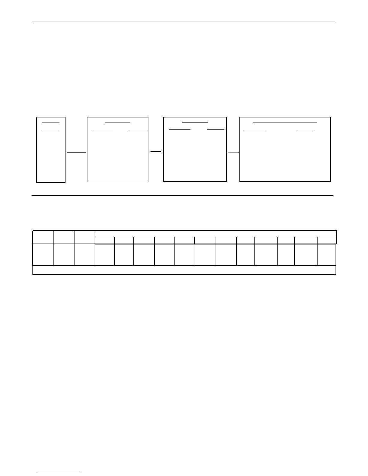
OPERATIONDUAL VANTAGE®700
AUXILIARY POWER OPERATION
Start the engine and set the IDLER control switch to
he desired operating mode. Full power is available
t
regardless of the welding control settings, if no weld-
ng current is being drawn.
i
TABLE B.5 DUAL VANTAGE®700 SIMULTANEOUS WELDING AND POWER LOADS
WELD
AMPS
0
100
200
300
400
500
600
PLUS
1 PHASE
WATTS AMPS
7,200 30
7,200 30
7,200 30
7,200 30
7,200 30
6,400 26
0 0
OR
WATTS AMPS
20,000 28
20,000 28
20,000 28
16,800 23
12,000 16
SIMULTANEOUS WELDING AND AUXILIARY POWER LOADS
It must be noted that the above auxiliary power ratings
are with no welding load.
Simultaneous welding and power loads are specified
in table B.5.
3 PHASE
6,400 9
0 0
O
R
BOTH 1 AND 3 PHASE
WATTS AMPS
------ 28
------ 28
------ 28
------ 23
7,200 -----6,400 ------
0 ------
Current
(Amps)
15
Voltage
(Volts)
240
TABLE B.6 DUAL VANTAGE®700 Extension Cord Length Recommendations
(Use the shortest length extension cord possible sized per the following table.)
Load
(Watts)
3,600
2.52mm 14AWG 4.02mm 12AWG 6.02mm 10AWG 10.02mm 8AWG 16.02mm 6AWG 25.02mm 4AWG
18
(60)
Conductor size is based on maximum 2.0% voltage drop.
Maximum Allowable Cord Length in m (ft.) for Conductor Size
23 (75) 46
(150) 69
(225)
107
(350)
183 (600)
B-10
 Loading...