

Page 1
Operator’s Manual
Dual Maverick®450
Register your machine:
www.lincolnelectric.com/register
Authorized Service and Distributor Locator:
www.lincolnelectric.com/locator
IM10481 | Issue D ate Feb-19
© Lincoln Global, Inc. All Rights Reserved.
For use with machines having Code Numbers:
12723
Need Help? Call 1.888.935.3877
to talk to a Service Representative
Hours of Operation:
8:00 AM to 6:00 PM (ET) Mon. thru Fri.
After hours?
Use “Ask the Experts” at lincolnelectric.com
A Lincoln Service Representative will contact you
no later than the following business day.
For Service outside the USA:
Email: globalservice@lincolnelectric.com
Save for future reference
Date Purchased
Code: (ex: 10859)
Serial: (ex: U1060512345)
Page 2
THANK YOU FOR SELECTING
A QUALITY PRODUCT BY
LINCOLN ELEC TRIC.
PLEASE EXAMINE CARTON AND EQUIPMENT FOR
DAMAGE IMMEDIATELY
When this equipment is shipped, title passes to the purchaser
upon receipt by the carrier. Consequently, claims for material
damaged in shipment must be made by the purchaser against the
transportation company at the time the shipment is received.
SAFETY DEPENDS ON YOU
Lincoln arc welding and cutting equipment is designed and built
with safety in mind. However, your overall safety can be increased
by proper installation ... and thoughtful operation on your part.
DO NOT INSTALL, OPERATE OR REPAIR THIS EQUIPMENT
WITHOUT READING THIS MANUAL AND THE SAFETY
PRECAUTIONS CONTAINED THROUGHOUT. And, most importantly,
think before you act and be careful.
This statement appears where the information must be followed
exactly to avoid serious personal injury or loss of life.
This statement appears where the information must be followed
to avoid minor personal injury or damage to this equipment.
KEEP YOUR HEAD OUT OF THE FUMES.
DON’T get too close to the arc.
Use corrective lenses if necessary
to stay a reasonable distance
away from the arc.
READ and obey the Safety Data
Sheet (SDS) and the warning label
that appears on all containers of
welding materials.
USE ENOUGH VENTILATION or
exhaust at the arc, or both, to
keep the fumes and gases from
your breathing zone and the general area.
IN A LARGE ROOM OR OUTDOORS, natural ventilation may be
adequate if you keep your head out of the fumes (See below).
USE NATURAL DRAFTS or fans to keep the fumes away
from your face.
If you de velop unusual symptoms, see your supervisor.
Perhaps the welding atmosphere and ventilation system
should be checked.
WEAR CORRECT EYE, EAR &
BODY PROTECTION
PROTECT your eyes and face with welding helmet
properly fitted and with proper grade of filter plate
(See ANSI Z49.1).
PROTECT your body from welding spatter and arc
flash with protective clothing including woolen
clothing, flame-proof apron and gloves, leather
leggings, and high boots.
PROTECT others from splatter, flash, and glare
with protective screens or barriers.
IN SOME AREAS, protection from noise may be appropriate.
BE SURE protective equipment is in good condition.
Also, wear safety glasses in work area
AT ALL TIMES.
SPECIAL SITUATIONS
DO NOT WELD OR CUT containers or materials which previously
had been in contact with hazardous substances unless they are
properly cleaned. This is extremely dangerous.
DO NOT WELD OR CUT painted or plated parts unless special
precautions with ventilation have been taken. They can release
highly toxic fumes or gases.
Additional precautionary measures
PROTECT compressed gas cylinders from excessive heat,
mechanical shocks, and arcs; fasten cylinders so they cannot fall.
BE SURE cylinders are never grounded or part of an
electrical circuit.
REMOVE all potential fire hazards from welding area.
ALWAYS HAVE FIRE FIGHTING EQUIPMENT READY FOR
IMMEDIATE USE AND KNOW HOW TO USE IT.
WARNING
CAUTION
Safety 01 of 04 - 5/16/2018
Page 3
SECTION A:
WARNINGS
CALIFORNIA PROPOSITION 65 WARNINGS
WARNING: Breathing diesel engine exhaust
exposes you to chemicals known to the State
of California to cause cancer and birth defects,
or other reproductive harm.
• Always start and operate the engine in a
well-ventilated area.
• If in an exposed area, vent the exhaust to the outside.
• Do not modify or tamper with the exhaust system.
• Do not idle the engine except as necessary.
For more information go to
www.P65 warnings.ca.gov/diesel
WARNING: This product, when used for welding or
cutting, produces fumes or gases which contain
chemicals known to the State of California to cause
birth defects and, in some cases, cancer. (California
Health & Safety Code § 25249.5 et seq.)
WARNING: Cancer and Reproductive Harm
www.P65warnings.ca.gov
ARC WELDING CAN BE HAZARDOUS. PROTECT
YOURSELF AND OTHERS FROM POSSIBLE SERIOUS
INJURY OR DEATH. KEEP CHILDREN AWAY.
PACEMAKER WEARERS SHOULD CONSULT WITH
THEIR DOCTOR BEFORE OPERATING.
Read and understand the following safety highlights. For
additional safety information, it is strongly recommended
that you purchase a copy of “Safety in Welding & Cutting ANSI Standard Z49.1” from the American Welding Society,
P.O. Box 351040, Miami, Florida 33135 or CSA Standard
W117.2-1974. A Free copy of “Arc Welding Safety” booklet
E205 is available from the Lincoln Electric Company,
22801 St. Clair Avenue, Cleveland, Ohio 44117-1199.
BE SURE THAT ALL INSTALLATION, OPERATION,
MAINTENANCE AND REPAIR PROCEDURES ARE
PERFORMED ONLY BY QUALIFIED INDIVIDUALS.
FOR ENGINE POWERED
EQUIPMENT.
1.a. Turn the engine off before troubleshooting
and maintenance work unless the
maintenance work requires it to be running.
1.b. Operate engines in open, well-ventilated areas or vent the engine
exhaust fumes outdoors.
1.c. Do not add the fuel near an open flame welding
arc or when the engine is running. Stop the
engine and allow it to cool before refueling to
prevent spilled fuel from vaporizing on contact
with hot engine parts and igniting. Do not spill fuel when filling
tank. If fuel is spilled, wipe it up and do not start engine until
fumes have been eliminated.
1.d. Keep all equipment safety guards, covers
and devices in position and in good repair.
Keep hands, hair, clothing and tools away
from V-belts, gears, fans and all other
moving parts when starting, operating or
repairing equipment.
1.e. In some cases it may be necessary to remove safety guards to
perform required maintenance. Remove guards only when
necessary and replace them when the maintenance requiring
their removal is complete. Always use the greatest care when
working near moving parts.
1.f. Do not put your hands near the engine fan. Do not attempt to
override the governor or idler by pushing on the throttle control
rods while the engine is running.
1.g. To prevent accidentally starting gasoline engines while turning
the engine or welding generator during maintenance work,
disconnect the spark plug wires, distributor cap or magneto wire
as appropriate.
1.h. To avoid scalding, do not remove the radiator
pressure cap when the engine is
hot.
ELECTRIC AND
MAGNETIC FIELDS MAY
BE DANGEROUS
2.a. Electric current flowing through any conductor
causes localized Electric and Magnetic Fields (EMF).
Welding current creates EMF fields around welding cables
and welding machines
2.b. EMF fields may interfere with some pacemakers, and
welders having a pacemaker should consult their physician
before welding.
2.c. Exposure to EMF fields in welding may have other health effects
which are now not known.
2.d. All welders should use the following procedures in order to
minimize exposure to EMF fields from the welding circuit:
2.d.1. Route the electrode and work cables together - Secure
them with tape when possible.
2.d.2. Never coil the electrode lead around your body.
2.d.3. Do not place your body between the electrode and work
cables. If the electrode cable is on your right side, the
work cable should also be on your right side.
2.d.4. Connect the work cable to the workpiece as close as possible to the area being welded.
2.d.5. Do not work next to welding power source.
SAFETY
Safety 02 of 04 - 5/16/2018
Page 4
ELECTRIC SHOCK
CAN KILL.
3.a. The electrode and work (or ground) circuits are
electrically “hot” when the welder is on. Do
not touch these “hot” parts with your bare skin or wet clothing.
Wear dry, hole-free gloves to insulate hands.
3.b. Insulate yourself from work and ground using dry insulation.
Make certain the insulation is large enough to cover your full area
of physical contact with work and ground.
In addition to the normal safety precautions, if
welding must be performed under electrically
hazardous conditions (in damp locations or while
wearing wet clothing; on metal structures such as
floors, gratings or scaffolds; when in cramped
positions such as sitting, kneeling or lying, if there
is a high risk of unavoidable or accidental contact
with the workpiece or ground) use the following
equipment:
• Semiautomatic DC Constant Voltage (Wire) Welder.
• DC Manual (Stick) Welder.
• AC Welder with Reduced Voltage Control.
3.c. In semiautomatic or automatic wire welding, the electrode,
electrode reel, welding head, nozzle or semiautomatic welding
gun are also electrically “hot”.
3.d. Always be sure the work cable makes a good electrical
connection with the metal being welded. The connection should
be as close as possible to the area being welded.
3.e. Ground the work or metal to be welded to a good electrical (earth)
ground.
3.f. Maintain the electrode holder, work clamp, welding cable and
welding machine in good, safe operating condition. Replace
damaged insulation.
3.g. Never dip the electrode in water for cooling.
3.h. Never simultaneously touch electrically “hot” parts of electrode
holders connected to two welders because voltage
between the
two can be the total of the open circuit voltage of both
welders.
3.i. When working above floor level, use a safety belt to protect
yourself from a fall should you get a shock.
3.j. Also see It ems 6.c. and 8.
ARC RAYS CAN BURN.
4.a. Use a shield with the proper filter and cover plates to protect your
eyes from sparks and the rays of the arc when welding or
observing open arc welding. Headshield and filter lens should
conform to ANSI Z87. I standards.
4.b. Use suitable clothing made from durable flame-resistant material
to protect your skin and that of your helpers from the arc rays.
4.c. Protect other nearby personnel with suitable, non-flammable
screening and/or warn them not to watch the arc nor expose
themselves to the arc rays or to hot spatter or metal.
FUMES AND GASES
CAN BE DANGEROUS.
5.a. Welding may produce fumes and gases
hazardous to health. Avoid breathing these
fumes and gases. When welding, keep your head out of the fume.
Use enough ventilation and/or exhaust at the arc to keep fumes
and gases away from the breathing zone. When welding
hardfacing (see instructions on container or SDS)
or on lead or cadmium plated steel and other
metals or coatings which produce highly toxic
fumes, keep exposure as low as possible and
within applicable OSHA PEL and ACGIH TLV limits
using local exhaust or mechanical ventilation
unless exposure assessments indicate otherwise.
In confined spaces or in some circumstances,
outdoors, a respirator may also be required.
Additional precautions are also required when
welding
on galvanized steel.
5. b. The operation of welding fume control equipment is affected by
various factors including proper use and positioning of the
equipment, maintenance of the equipment and the specific
welding procedure and application involved. Worker exposure
level should be checked upon installation and periodically
thereafter to be certain it is within applicable OSHA PEL and
ACGIH TLV limits.
5.c. Do not weld in locations near chlorinated hydrocarbon vapors
coming from degreasing, cleaning or spraying operations. The
heat and rays of the arc can react with solvent vapors to form
phosgene, a highly toxic gas, and other irritating products.
5.d. Shielding gases used for arc welding can displace air and
cause
injury or death. Always use enough ventilation, especially in
confined areas, to insure breathing air is safe.
5.e. Read and understand the manufacturer’s instructions for this
equipment and the consumables to be used, including the
Safety Data Sheet (SDS) and follow your employer’s safety
practices. SDS forms are available from your welding
distributor or from the manufacturer.
5.f. Also see item 1.b.
SAFETY
Safety 03 of 04 - 5/16/2018
Page 5
WELDING AND CUTTING
SPARKS CAN CAUSE
FIRE OR EXPLOSION.
6.a. Remove fire hazards from the welding area. If
this is not possible, cover them to prevent the welding sparks
from starting a fire. Remember that welding sparks and hot
materials from welding can easily go through small cracks and
openings to adjacent areas. Avoid welding near hydraulic lines.
Have a fire extinguisher readily available.
6.b. Where compressed gases are to be used at the job site, special
precautions should be used to prevent hazardous situations.
Refer to “Safety in Welding and Cutting” (ANSI Standard Z49.1)
and the operating information for the equipment being used.
6.c. When not welding, make certain no part of the electrode circuit is
touching the work or ground. Accidental contact can cause
overheating and create a fire hazard.
6.d. Do not heat, cut or weld tanks, drums or containers until the
proper steps have been taken to insure that such procedures
will not cause flammable or toxic vapors from substances inside.
They can cause an explosion even though they have been
“cleaned”. For information, purchase “Recommended Safe
Practices for the Preparation for Welding and Cutting of
Containers and Piping That Have Held Hazardous Substances”,
AWS F4.1 from the American Welding Society
(see address above).
6.e. Vent hollow castings or containers before heating, cutting or
welding. They may explode.
6.f. Sparks and spatter are thrown from the welding arc. Wear oil free
protective garments such as leather gloves, heavy shirt, cuffless
trousers, high shoes and a cap over your hair. Wear ear plugs
when welding out of position or in confined places. Always wear
safety glasses with side shields when in a welding area.
6.g. Connect the work cable to the work as close to the welding area
as practical. Work cables connected to the building framework or
other locations away from the welding area increase the
possibility of the welding current passing through lifting chains,
crane cables or other alternate circuits. This can create fire
hazards or overheat lifting chains or cables until they fail.
6.h. Also see item 1.c.
6.I. Read and follow NFPA 51B “Standard for Fire Prevention During
Welding, Cutting and Other Hot Work”, available from NFPA, 1
Batterymarch Park, PO box 9101, Quincy, MA 022690-9101.
6.j. Do not use a welding power source for pipe thawing.
CYLINDER MAY EXPLODE IF
DAMAGED.
7.a. Use only compressed gas cylinders containing
the correct shielding gas for the process used
and properly operating regulators designed for
the gas and pressure used. All hoses, fittings,
etc. should be suitable for the application and
maintained in good condition.
7.b. Always keep cylinders in an upright position securely chained to
an undercarriage or fixed support.
7.c. Cylinders should be located:
• Away from areas where they may be struck or subjected
to physical damage.
• A safe distance from arc welding or cutting operations
and any other source of heat, sparks, or flame.
7.d. Never allow the electrode, electrode holder or any other
electrically “hot” parts to touch a cylinder.
7.e. Keep your head and face away from the cylinder valve outlet
when opening the cylinder valve.
7.f. Valve protection caps should always be in place and hand tight
except when the cylinder is in use or connected for use.
7.g. Read and follow the instructions on compressed gas cylinders,
associated equipment, and CGA publication P-l, “Precautions for
Safe Handling of Compressed Gases in Cylinders,” available from
the Compressed Gas Association, 14501 George Carter Way
Chantilly, VA 20151.
FOR ELECTRICALLY
POWERED EQUIPMENT.
8.a. Turn off input power using the disconnect
switch at the fuse box before working on
the equipment.
8.b. Install equipment in accordance with the U.S. National Electrical
Code, all local codes and the manufacturer’s recommendations.
8.c. Ground the equipment in accordance with the U.S. National
Electrical Code and the manufacturer’s recommendations.
Refer to
http://www.lincolnelectric.com/safety
for additional safety information.
SAFETY
Safety 04 of 04 - 5/16/2018
Page 6

2
SAFETY
Electromagnetic Compatibility (EMC)
Conformance
Products displaying the CE mark are in conformity with European Community Council Directive of 15 Dec
2004 on the approximation of the laws of the Member States relating to electromagnetic compatibility,
2004/108/EC. It was manufactured in conformity with a national standard that implements a harmonized
standard: EN 60974-10 Electromagnetic Compatibility (EMC) Product Standard for Arc Welding Equipment.
It is for use with other Lincoln Electric equipment. It is designed for industrial and professional use.
Introduction
All electrical equipment generates small amounts of electromagnetic emission. Electrical emission may be
transmitted through power lines or radiated through space, similar to a radio transmitter. When emissions
are received by other equipment, electrical interference may result. Electrical emissions may affect many
kinds of electrical equipment; other nearby welding equipment, radio and TV reception, numerical controlled
machines, telephone systems, computers, etc. Be aware that interference may result and extra precautions
may be required when a welding power source is used in a domestic establishment.
Installation and Use
The user is responsible for installing and using the welding equipment according to the manufacturer’s
instructions. If electromagnetic disturbances are detected then it shall be the responsibility of the user of the
welding equipment to resolve the situation with the technical assistance of the manufacturer. In some cases
this remedial action may be as simple as earthing (grounding) the welding circuit, see Note. In other cases it
could involve construction of an electromagnetic screen enclosing the power source and the work complete
with associated input filters. In all cases electromagnetic disturbances must be reduced to the point where
they are no longer troublesome.
Note: The welding circuit may or may not be earthed for safety reasons according to national
codes. Changing the earthing arrangements should only be authorized by a person who is
competent to access whether the changes will increase the risk of injury, e.g., by allowing
parallel welding current return paths which may damage the earth circuits of other equipment.
Assessment of Area
Before installing welding equipment the user shall make an assessment of potential electromagnetic problems in the surrounding area. The following shall be taken into account:
a) other supply cables, control cables, signaling and telephone cables; above, below and adjacent to the
welding equipment;
b) radio and television transmitters and receivers;
c) computer and other control equipment;
d) safety critical equipment, e.g., guarding of industrial equipment;
e) the health of the people around, e.g., the use of pacemakers and hearing aids;
f) equipment used for calibration or measurement
g) the immunity of other equipment in the environment. The user shall ensure that other equipment being
used in the environment is compatible. This may require additional protection measures;
h) the time of day that welding or other activities are to be carried out.
Page 7

3
SAFETY
Electromagnetic Compatibility (EMC)
The size of the surrounding area to be considered will depend on the structure of the building and other
activities that are taking place. The surrounding area may extend beyond the boundaries of the premises.
Methods of Reducing Emissions
Mains Supply
Welding equipment should be connected to the mains supply according to the manufacturer’s recommendations. If interference occurs, it may be necessary to take additional precautions such as filtering of the mains
supply. Consideration should be given to shielding the supply cable of permanently installed welding equipment, in metallic conduit or equivalent. Shielding should be electrically continuous throughout its length. The
shielding should be connected to the welding power source so that good electrical contact is maintained
between the conduit and the welding power source enclosure.
Maintenance of the Welding Equipment
The welding equipment should be routinely maintained according to the manufacturer’s recommendations.
All access and service doors and covers should be closed and properly fastened when the welding equipment is in operation. The welding equipment should not be modified in any way except for those changes
and adjustments covered in the manufacturers instructions. In particular, the spark gaps of arc striking and
stabilizing devices should be adjusted and maintained according to the manufacturer’s recommendations.
Welding Cables
The welding cables should be kept as short as possible and should be positioned close together, running at
or close to floor level.
Equipotential Bonding
Bonding of all metallic components in the welding installation and adjacent to it should be considered.
However, metallic components bonded to the work piece will increase the risk that the operator could
receive a shock by touching these metallic components and the electrode at the same time. The operator
should be insulated from all such bonded metallic components.
Earthing of the Workpiece
Where the workpiece is not bonded to earth for electrical safety, not connected to earth because of its size
and position, e.g., ships hull or building steelwork, a connection bonding the workpiece to earth may reduce
emissions in some, but not all instances. Care should be taken to prevent the earthing of the workpiece
increasing the risk of injury to users, or damage to other electrical equipment. Where necessary, the connection of the workpiece to earth should be made by a direct connection to the workpiece, but in some countries
where direct connection is not permitted, the bonding should be achieved by suitable capacitance, selected
according to national regulations.
Screening and Shielding
Selective screening and shielding of other cables and equipment in the surrounding area may alleviate problems of interference. Screening of the entire welding installation may be considered for special
applications
1.
_________________________
1
Portions of the preceding text are contained in EN 60974-10: “Electromagnetic Compatibility (EMC) product standard for arc welding equipment.”
Page 8

INSTALLATION ...........................................................................................................................SECTION A
TECHNICAL SPECIFICATIONS...................................................................................................................A-1
VRD (VOLTAGE REDUCTION DEVICE).......................................................................................................A-2
LOCATION AND VENTILATION ..................................................................................................................A-3
STORING ............................................................................................................................................A-3
STACKING ............................................................................................................................................A-3
ANGLE OF OPERATION ............................................................................................................................A-3
LIFTING ............................................................................................................................................A-3
HIGH ALTITUDE OPERATION ....................................................................................................................A-4
HIGH TEMPERATURE OPERATION ............................................................................................................A-4
TOWING ............................................................................................................................................A-4
VEHICLE MOUNTING................................................................................................................................A-4
PRE-OPERATION ENGINE SERVICE...........................................................................................................A-4
OIL ............................................................................................................................................A-4
FUEL - USE DIESEL FUEL ONLY ...............................................................................................................A-5
ENGINE COOLANT ...................................................................................................................................A-5
BATTERY CONNECTION ...........................................................................................................................A-5
MUFFLER OUTLET PIPE ...........................................................................................................................A-5
SPARK ARRESTOR...................................................................................................................................A-5
CASE FRONT CONTROLS.........................................................................................................................A-6
WELDING TERMINALS .............................................................................................................................A-8
WELDING OUTPUT CABLES......................................................................................................................A-8
MACHINE GROUNDING.............................................................................................................................A-8
REMOTE CONTROL .................................................................................................................................A-9
AUXILIARY POWER RECEPTACLES ..........................................................................................................A-9
STANDBY POWER CONNECTIONS............................................................................................................A-9
CONNECTION OF WIRE FEEDERS WITH CONTROL CABLE (14 PIN)..........................................................A-10
CONNECTION OF ACROSS THE ARC WIRE FEEDERS TO THE DUAL MAVERICK
®
450 ..............................A-11
OPERATION ................................................................................................................................SECTION B
GENERAL DESCRIPTION ..........................................................................................................................B-1
FOR AUXILIARY POWER: ..........................................................................................................................B-1
ENGINE OPERATION ................................................................................................................................B-1
ADD FUEL ............................................................................................................................................B-2
HAND PRIMER BUTTON...........................................................................................................................B-2
BREAK-IN PERIOD ...................................................................................................................................B-2
RECOMMENDED APPLICATIONS..............................................................................................................B-2
GENERATOR............................................................................................................................................B-2
ENGINE OPERATION ................................................................................................................................B-3
TYPICAL FUEL CONSUMPTION.................................................................................................................B-3
WELDER OPERATION...............................................................................................................................B-4
PARALLELING..........................................................................................................................................B-6
AUXILIARY POWER OPERATION................................................................................................................B-7
DISPLAY OPERATION...............................................................................................................................B-8
ACCESSORIES ............................................................................................................................SECTION C
MAINTENANCE...........................................................................................................................SECTION D
ROUTINE AND PERIODIC MAINTENANCE..................................................................................................D-1
ENGINE MAINTENANCE ...........................................................................................................................D-1
AIR FILTER ............................................................................................................................................D-1
FUEL FILTERS .........................................................................................................................................D-3
COOLING SYSTEM...................................................................................................................................D-3
NAMEPLATES / WARNING DECALS MAINTENANCE ..................................................................................D-3
WELDER / GENERATOR MAINTENANCE ..................................................................................................D-3
FAN BELT CHANGE..................................................................................................................................D-3
OIL CHANGE............................................................................................................................................D-3
BATTERY HANDLING ...............................................................................................................................D-4
PREVENTING ELECTRICAL DAMAGE.........................................................................................................D-4
PREVENTING BATTERY DISCHARGE.........................................................................................................D-4
PREVENTING BATTERY BUCKLING ...........................................................................................................D-4
CHARGING THE BATTERY ........................................................................................................................D-4
4
TABLE OF CONTENTS
Page 9

TROUBLESHOOTING ...................................................................................................................SECTION E
DIAGRAMS ................................................................................................................................SECTION G
PARTS LIST...............................................................................................PARTS.LINCOLNELECTRIC.COM
CONTENT/DETAILS MAY BE CHANGED OR UPDATED WITHOUT NOTICE. FOR MOST CURRENT INSTRUCTION
MANUALS, GO TO PARTS.LINCOLNELECTRIC.COM.
Page 10
A-1
INSTALLATIONDUAL MAVERICK®450
INSTALLATION
TECHNICAL SPECIFICATIONS DUAL MAVERICK®450 (K4381-1) CODE 12723
Make/Model Description Speed (RPM) Displacement Starting Dry Capacities
cu. in. (ltrs.) System
3 cylinder High Idle 3000 69 (1.1)
12VDC Battery &
Fuel: 20 gal.
Perkins
®
26.4 HP (19.7kw) starter (75.6 L)
403D-11 3000 RPM Full Load 3000
Bore x Stroke inch (mm)
Oil: 1.16 gal. (4.4L)
Diesel Engine
Low Idle 2100
3.03 X 3.19
Radiator Coolant:
(71 x 81mm) 5.0gal. (18.9L)
INPUT - DIESEL ENGINE
RATED OUTPUT @ 104°F(40°C) - WELDER
SINGLE MODE DUAL MODE
Duty Cycle Welding Volts at Rated Duty Cycle Welding Volts at Rated
Output Amps Output Amps
100% 350 A 34 Volts 100% 225 A 26 Volts
100% 450 A 26 volts 100% 210 A 28.4 Volts
OUTPUT @ 104°F (40°C) – WELDER AND GENERATOR
SINGLE MODE DUAL MODE
Welding Range Welding Range
50-450 Amps CC 30 – 225 Amps CC
30-370 Amps CV 30 – 230 Amps CV
20 - 255 Amps TIG 20 - 255 Amps TIG
Open Circuit Voltage Open Circuit Voltage
60 MAX OCV @ 3000 RPM 60 MAX OCV @ 3000 RPM
Auxiliary Power Auxiliary Power
220 VAC (2) x 6600 Watts, 50 Hz, Single Phase 220 VAC (2) x 6600 Watts, 50 Hz, Single Phase
380 VAC x 13000 Watts, 50 Hz, Three Phase 380 VAC x 13000 Watts, 50 Hz, Three Phase
PHYSICAL DIMENSIONS
Height
(2)
Width
(3)
Depth Weight
36.1 in 27.0 in. 65.0 in. 1155 lbs.
(917 mm) (686 mm) (1651 mm) (524 kg)
(Approx.)
Lift Bail weight rating 2130 lbs. (966 kg.) Maximum.
(1) Output rating in watts is equivalent to volt-amperes at unity power factor.
Output voltage is within +/- 10% at all loads up to rated capacity. When welding, available auxiliary power will be reduced.
(2) Top of Enclosure, add 8.3” (211mm) for exhaust pipe, also add 3.65”(93mm) for metal skid.
(3) Without metal skid.
Page 11
A-2
INSTALLATIONDUAL MAVERICK®450
SAFETY PRECAUTIONS
Only qualified personnel should install,
use, or service this equipment.
Do not attempt to use this equipment until you have
thoroughly read the engine manufacturer’s manual supplied
with your welder. It includes important safety precautions,
detailed engine starting, operating and maintenance
instructions, and parts lists.
ELECTRIC SHOCK can kill.
• Do not touch electrically live parts or
electrode with skin or wet clothing.
• Insulate yourself from work and ground
• Always wear dry insulating gloves.
ENGINE EXHAUST can kill.
• Use in open, well ventilated areas or vent
exhaust outside.
MOVING PARTS can injure.
• Do not operate with doors open or
guards off.
• Stop engine before servicing.
• Keep away from moving parts.
See additional warning information at front of this
operator’s manual.
VRD (VOLTAGE REDUCTION DEVICE)
The VRD feature provides additional safety in the Stick, Pipe, Tig
and Gouge modes especially in an environment with a higher risk
of electric shock such as wet areas and hot humid sweaty
conditions.
The VRD reduces the OCV (Open Circuit Voltage) at the welding
output terminals while not welding to less than 13V DC when the
resistance of the output circuit is above 200Ω (ohms).
The VRD requires that the welding cable connections be kept in
good electrical condition because poor connections will contribute
to poor starting. Having good electrical connections also limits the
possibility of other safety issues such as heat-generated damage,
burns and fires.
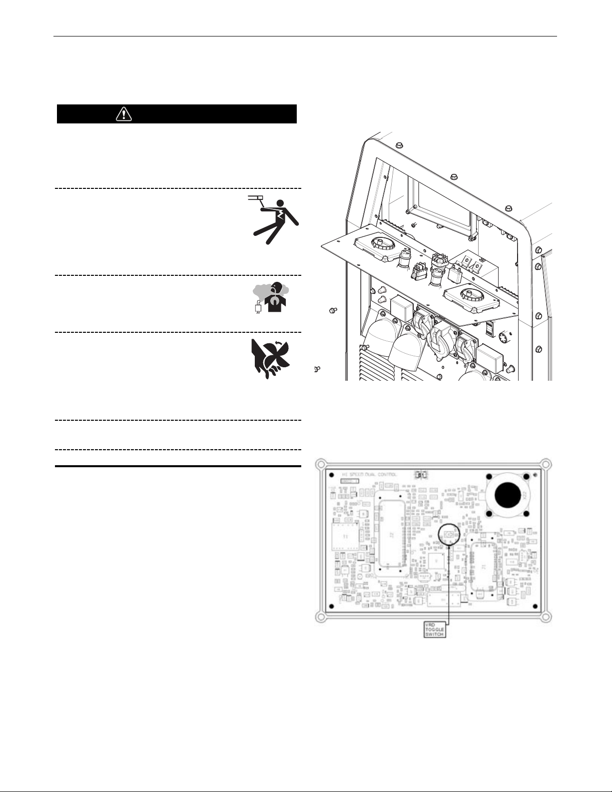
The machine is shipped with the VRD switch in the “OFF” position.
To turn it "ON" or "OFF":
1. Switch the High Idle/Run - Stop switch to the Stop position.
2. Remove the 8 screws on the upper panel (Fig A.1). Pull out
the panel to have access to the PC control boards (Fig A.1).
FIGURE A.1
3. Locate VRD switches (as marked in Fig A.2) on both PC
control boards. Left position on each switch indicates "OFF"
state; right position on each switch indicates "ON" state. PC
Control Board on the left is for settings for the left user. PC
Control board on the right is for settings for the right user.
FIGURE A.2
4. Set VRD switches as desired. Toggle left for “OFF”. Toggle
right for “ON”
5. Reinstall the upper panel with screws from Step 2. Turn on
the High Idle/Run switch. Confirm VRD status on the LCD
screen display related to that PC board.
When the VRD switch is in the "ON" position. The display will
show a green tab with "VOLTS<30". If the VRD switch is in the
"ON" position and stud voltage is above 30 volts or while welding,
the display will show a red tab with "VOLTS>30".
WARNING
Page 12
A-3
INSTALLATIONDUAL MAVERICK®450
LOCATION AND VENTILATION
The welder should be located to provide an unrestricted flow of
clean, cool air to the cooling air inlets and to avoid restricting the
cooling air outlets. Locate the welder so that the engine exhaust
fumes are properly vented to an outside area.
DO NOT MOUNT OVER COMBUSTIBLE SURFACES
Where there is a combustible surface directly under
stationary or fixed electrical equipment, that surface should
be covered with a steel plate at least .06”(1.6mm) thick,
which should extend not less than 5.90”(150mm) beyond the
equipment on all sides.
STORING
1. Store the machine in a cool, dry place when it is not in use.
Protect it from dust and dirt. Keep it where it can’t be
accidentally damaged from construction activities, moving
vehicles, and other hazards.
2. Drain the engine oil and refill with fresh 10W30 oil. Run the
engine for about five minutes to circulate oil to all the parts.
See the MAINTENANCE section of this manual for details on
changing oil.
3. Remove the battery, recharge it, and adjust the electrolyte
level. Store the battery in a dry, dark place.
STACKING
Dual Maverick®450 machines cannot be stacked.
ANGLE OF OPERATION
To achieve optimum engine performance the
Dual Maverick®450 should be run in a level position.
The maximum angle of operation for the machine is 35 degrees
continuous in all directions.
When operating the welder at an angle, provisions must be made
for checking and maintaining the oil level at the normal (FULL) oil
capacity. The effective fuel capacity will be slightly less than the
specified 20 gal.(75.7 ltrs.).
LIFTING
The Dual Maverick®450 weighs approximately 1294 lbs.(587 kg)
with a full tank of fuel, 1155 lbs.(524kg) without fuel. A lift bail
and fork pockets are installed on the machine. Lift welder ONLY
using the lift bail or fork pockets.
FALLING EQUIPMENT can cause
injury.
• Lift only with equipment of adequate
lifting capacity.
• Be sure machine is stable when lifting.
• Do not lift this machine using lift bail if it is equipped
with a heavy accessory such as trailer or gas cylinder.
• Do not lift machine if lift bail is damaged.
• Do not operate machine while suspended from lift bail.
• DO NOT EXCEED MAXIMUM LIFT BAIL WEIGHT
RATING.
( SEE TECHNICAL SPECIFICATIONS PAGE)
CAUTION
WARNING
Page 13
A-4
INSTALLATIONDUAL MAVERICK®450
HIGH ALTITUDE OPERATION
The naturally aspirated engine will run correctly up to an attitude
of 600 m (2000 ft.) If the engine is to operate at an attitude above
this, an increase in smoke may be seen. This is normal for a
naturally aspirated engine.
HIGH TEMPERATURE OPERATION
At temperatures above 40°C (104°F), output voltage derating may
be necessary. For maximum output current ratings, follow the
table below.
DESERT DUTY RATINGS
TOWING
The recommended trailer for use with this equipment for road, inplant and yard towing by a vehicle
(1)
is Lincoln’s K2636-1. If the
user adapts a non-Lincoln trailer, he must assume responsibility
that the method of attachment and usage does not result in a
safety hazard nor damage the welding equipment. Some of the
factors to be considered are as follows:
1. Design capacity of trailer vs. weight of Lincoln equipment and
likely additional attachments.
2. Proper support of, and attachment to, the base of the welding
equipment so that there will be no undue stress to the trailer’s
framework.
3. Proper placement of the equipment on the trailer to insure
stability side to side and front to back when being moved and
when standing by itself.
4. Typical conditions of use, such as travel speed, roughness of
surface on which the trailer will be operated, and
environmental conditions.
5. Proper preventative maintenance of trailer.
6. Conformance with federal, state and local laws(1).
(1) Consult applicable federal, state and local laws regarding specific require-
ments for use on public highways.
VEHICLE MOUNTING
Improperly mounted concentrated loads may cause
unstable vehicle handling and tires or other components to
fail.
• Only transport this Equipment on serviceable vehicles
which are rated and designed for such loads.
• Distribute, balance and secure loads so vehicle is
stable under conditions of use.
• Do not exceed maximum rated loads for components
such as suspension, axles and tires.
• Mount equipment base to metal bed or frame of vehicle.
• Follow vehicle manufacture’s instructions.
PRE-OPERATION ENGINE SERVICE
READ the engine operating and maintenance instructions supplied
with this machine.
• Keep hands away from the engine muffler
or HOT engine parts.
• Stop engine and allow to cool before
fuelling.
• Do not smoke when fuelling.
• Fill fuel tank at a moderate rate and do not over-fill.
• Wipe up spilled fuel and allow fumes to clear before
starting engine.
• Keep sparks and flame away from tank.
OIL
The Dual Maverick®450 is shipped with the engine
crankcase filled with high quality SAE 10W-30 oil (API class CD or
better). Check the engine oil levels before starting the engine. If it
is not up to the full mark on the dip stick, add oil as required.
Check the oil level every four hours of running time during the first
35 running hours. Refer to the engine Operator’s Manuals for
specific oil recommendations and break-in information. The oil
change interval is dependent on the quality of the oil and the
operating environment. Refer to the engine Operator’s Manuals for
the proper service and maintenance intervals.
WARNING
AMPS 450 450 425 400
VOLTS 26 26 26 26
DUTY CYCLE 100% 90% 60% 60%
AMBIENT TEMP 40 45 50 55
WARNING
Page 14
A-5
INSTALLATIONDUAL MAVERICK®450
FUEL - USE DIESEL FUEL ONLY
Fill the fuel tank with clean, fresh diesel fuel. The
capacity of the fuel tank is approximately 20 gallons
(75.7 liters). See engine Operator’s Manual for specific
fuel recommendations. Running out of fuel may require bleeding
the fuel injection pump.
NOTE: Before starting the engine, open the fuel shutoff valve on
the fuel filter located on the liftbale.
ENGINE COOLANT
HOT COOLANT can burn skin.
Do not remove cap if radiator is hot.
The welder is shipped with the engine and radiator
filled with a 50% mixture of ethylene glycol and
water. See the MAINTENANCE section and the
engine Operator’s Manual for more information on
coolant.
BATTERY CONNECTION
GASES FROM BATTERY can explode.
Keep sparks, flame and cigarettes away from
battery.
To prevent EXPLOSION when:
• INSTALLING A NEW BATTERY — disconnect negative
cable from old battery first and connect to new battery
last.
• CONNECTING A BATTERY CHARGER — remove
battery from welder by disconnecting negative cable
first, then positive cable and battery clamp. When
reinstalling, connect negative cable last. Keep well
ventilated.
• USING A BOOSTER — connect positive lead to battery
first then connect negative lead to negative battery lead
at engine foot.
BATTERY ACID can burn eyes and
skin.
• Wear gloves and eye protection and be
careful when working near battery.
• Follow instructions printed on battery.
IMPORTANT: To prevent ELECTRICAL DAMAGE WHEN:
a) Installing new battery.
b) Using a booster.
Use correct polarity — NEGATIVE GROUND.
The Dual Maverick®450 is shipped with the negative battery
cable disconnected. Before you operate the machine, make sure
the High Idle / Run - Stop switch is in the STOP position and
attach the disconnected cable securely to the negative (-) battery
terminal.
Remove the insulating cap from the negative battery terminal.
Replace and tighten negative battery cable terminal. NOTE: This
machine is furnished with a wet charged battery; if unused for
several months, the battery may require a booster charge. Be sure
to use the correct polarity when charging the battery.
MUFFLER OUTLET PIPE
Remove the plastic plug covering the muffler outlet tube. Using
the clamp provided secure the outlet pipe to the outlet tube with
the pipe positioned such that it will direct the exhaust in the
desired position.
SPARK ARRESTOR
Some federal, state or local laws may require that petrol or diesel
engines be equipped with exhaust spark arrestors when they are
operated in certain locations where unarrested sparks may
present a fire hazard. When required by local regulations, a
suitable spark arrestor, must be installed and properly maintained.
An incorrect arrestor may lead to damage to the engine or
adversely affect performance.
WARNING
WARNING
CAUTION
Page 15
A-6
INSTALLATIONDUAL MAVERICK®450
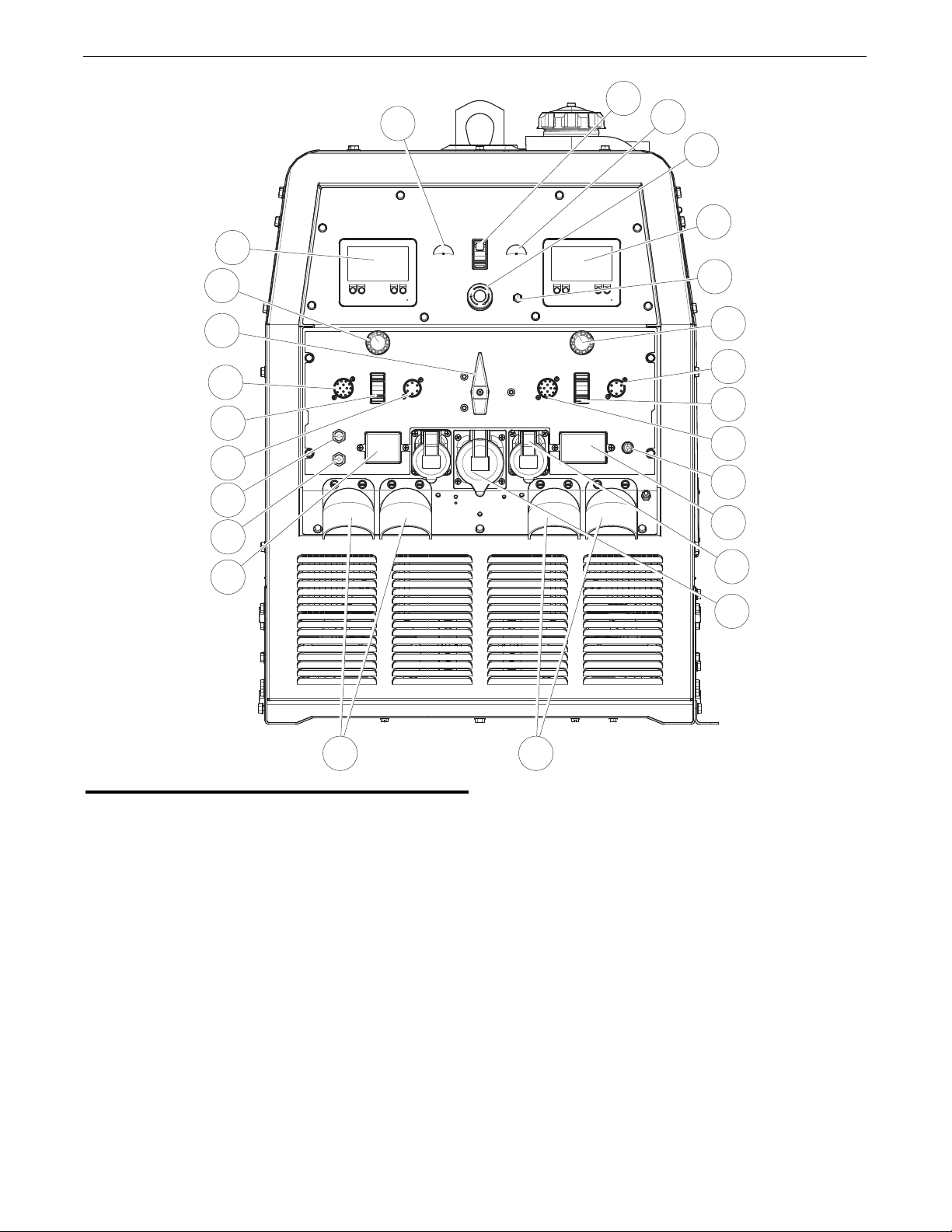
CASE FRONT CONTROLS
1. LCD SCREEN, IP67 RATED OPERATOR A - The LCD screen
displays information about welding mode, output voltage or
current, engine status and machine settings. It allows
operator to select welding mode and read the output voltage
or current when presetting using the output control knob.
During welding, the screen displays the actual output voltage
(VOLTS) and current (AMPS). A memory feature holds the
screens on for 5 seconds after welding is stopped. This
allows the operator to read the actual current and voltage just
prior to when welding was ceased. In engine status section,
information about engine hours, filter condition, engine oil
and other service items are displayed..
2. OUTPUT CONTROL OPERATOR A - The OUTPUT KNOB is used
to preset the output voltage or current as displayed on the
LCD screen for the six welding modes. When in the ARC
GOUGING or CV-WIRE modes and when a remote control is
connected to the 6-Pin or 14-Pin Connector, the auto-sensing
circuit automatically switches the OUTPUT CONTROL from
control at the welder to the remote control. When in
DOWNHILL PIPE and CC-STICK modes if a remote control is
connected to the 6-Pin or 14 Pin Connectors, the output is
controlled by the remote and the output control on the
machine is used to set the maximum current range for the
remote.
3. SINGLE/DUAL OPERATOR MODE SWITCH - The switch allows
the user to choose between Single Operator and Dual
Operator weld modes. Single Operator mode is when the
switch is in the “Left” position. Dual Operator mode is when
the switch is in the “Right” position.
4. 14-PIN WIRE FEEDER CONNECTION OPERATOR A - For
attaching wire feeder control cables. Includes contactor
closure circuit, auto-sensing remote control circuit, and 42V
power. The remote control circuit operates the same as the
6 Pin Amphenol. NOTE: That 115V is not available.
5. WIRE FEEDER POLARITY SWITCH - Matches the polarity of the
wire feeder voltmeter to the polarity of the electrode.
6. 6-PIN REMOTE CONTROL CONNECTOR OPERATOR A - For
attaching optional remote control equipment. Includes autosensing remote control circuit.
14
13
1
15
16
18
2
3
4
5
6
7
8
9
17
19
20
21
22
24
23
10
11
12 25
Page 16

A-7
INSTALLATIONDUAL MAVERICK®450
7. 15 AMP CIRCUIT BREAKER - Auxiliary output breaker protects
the 220V, single phase receptacle.
8. 15 AMP CIRCUIT BREAKER - Auxiliary output breaker protects
the 220V, single phase receptacle.
9. 25 AMP CIRCUIT BREAKER - Auxiliary output breaker protects
the 380V, three phase receptacle.
10. 220VAC SINGLE PHASE AC EURO PLUGS (QTY 2) - European
(IEC-309) receptacle rated up to 16 amps and is IP44 rated.
11. 380V THREE PHASE AC EURO PLUG- European (IEC-309)
receptacle rated up to 32 amps and is IP44 rated.
12. POSITIVE AND NEGATIVE WELD TERMINAL OPERATOR A -
Provides a connection point for the electrode and work
cables.
13. GLOW PLUG PUSH BUTTON - When pushed activates the
glow plugs. Glow plug should not be activated for more than
20 seconds continuously.
14. RUN / STOP SWITCH - RUN position energizes the engine
prior to starting. STOP position stops the engine. The oil
pressure interlock switch prevents battery drain if the switch
is left in the RUN position and the engine is not operating.
15. START PUSH BUTTON- Energizes the starter motor to crank
the engine.
16. EMERGENCY STOP – Push to stop the engine immediately.
The stop button needs to be manually reset after use in order
to turn on the engine again.
17. BATTERY BREAKER - For protection of Battery Charging
Circuit.
18. LCD SCREEN, IP67 RATED OPERATOR B
19. OUTPUT CONTROL OPERATOR B
20. 6-PIN REMOTE CONTROL CONNECTION OPERATOR B
21. WIRE FEEDER POLARITY SWITCH OPERATOR B
22. 14-PIN WIRE FEEDER CONNECTION OPERATOR B
23. RESIDUAL CURRENT DEVICE – 30mA- Instantly breaks the
auxiliary circuit to prevent serious harm from an ongoing
electric shock.
24. WIRE FEEDER CIRCUIT BREAKER- 42V WIRE FEEDER
BREAKERS
25. POSITIVE AND NEGATIVE WELD TERMINAL OPERATOR B
Page 17

A-8
INSTALLATIONDUAL MAVERICK®450
WELDING TERMINALS
From the main screen select MIG / FCAW / TIG welding. Press
knob to select screen that shows Weld Output Override. (Figure
A.3)
Press knob to select either OFF - output controlled by welding gun
switch or ON - output always ON (electrode always hot).
FIGURE A.3
WELDING OUTPUT CABLES
With the engine off, connect the electrode and work cables to the
terminals provided. These connections should be checked
periodically and tightened if necessary.
Listed in Table A.1 are copper cable sizes recommended for the
rated current and duty cycle. Lengths stipulated are the distance
from the welder to work and back to the welder again. Cable sizes
are increased for greater lengths primarily for the purpose of
minimizing cable voltage drop.
TABLE A.1 TOTAL COMBINED LENGTH OF
ELECTRODE AND WORK CABLES
MACHINE GROUNDING
Because this portable engine driven welder creates its own power,
it is not necessary to connect its frame to an earth ground, unless
the machine is connected to premises wiring (home, shop, etc.).
To prevent dangerous electric shock, other equipment to
which this engine driven welder supplies power must:
• Be grounded to the frame of the welder using a
grounded type plug or be double insulated.
• Do not ground the machine to a pipe that carries
explosive or combustible material.
When this welder is mounted on a truck or trailer, its frame must
be securely connected to the metal frame of the vehicle. When
this engine driven welder is connected to premises wiring such as
that in a home or shop, its frame must be connected to the system
earth ground. See further connection instructions in the section
entitled “Standby Power Connections” as well as
the article on grounding in the latest National Electrical Code and
the local codes.
In general, if the machine is to be grounded, it should be
connected with a #8 or larger copper wire to a solid earth ground
such as a metal ground stake going into the ground for at least 10
Feet or to the metal framework of a building which has been
effectively grounded.
The National Electric Code lists a number of alternate means of
grounding electrical equipment. A machine grounding stud
marked with the symbol is provided on the front of the welder.
WARNING
?
Remote
Weld Output Override
OFF
(OUTPUT CONTROLLED
BY TORCH/FOOT PEDAL
SWITCH)
ON
(OUTPUT ALWAYS ON)
Press knob to select
Output
ON
Cable Length
Cable Size for
400 Amps
60% Duty
Cycle
Cable Size for
300 AMPS
60% Duty
Cycle
Lengths up to
100 ft. (30m)
2/0 AWG 1/0 AWG
100 ft. (30m) to
150 ft. (61m)
2/0 AWG 1/0 AWG
150 ft. (46m) to
200 ft. (61m)
3/0 AWG 2/0
Page 18

REMOTE CONTROL
The Dual Maverick®450 is equipped with a 6-pin and a 14-pin
connector. The 6-pin connector is for connecting the K857 or
K857-1 Remote Control or for TIG welding, the K870 foot Amptrol
or the K963-3 hand Amptrol. When in the CC-STICK, ARC
GOUGING, TIG or CV-WIRE modes and when a remote control is
connected to the 6-pin Connector, the auto-sensing circuit
automatically switches the OUTPUT control from control at the
welder to remote control.
The 14-pin connector is used to directly connect a wire feeder
control cable. In the CV-WIRE mode, when the control cable is
connected to the 14-pin connector, the auto-sensing circuit
automatically makes the Output Control inactive and the wire
feeder voltage control active.
In each case, once connected control maybe optionally changed
back to the control panel using the display remote button. The
maximum and minimum current range can be setup / modified in
display.
NOTE: When a wire feeder with a built in welding voltage
control is connected to the 14-pin connector, do not
connect anything to the 6-pin connector.
AUXILIARY POWER RECEPTACLES
For heavy loads switch the "HIGH IDLE/RUN-STOP" control switch
to the "High Idle" mode and set weld output at max.
The auxiliary power of the Dual Maverick®450 consists of two
220 VAC European (IEC-309) 15 Amp receptacles protected by two
15 Amp circuit breakers.
One 380 VAC European (IEC-309) 21 Amp receptacle that is
protected by a 25 Amp 3 Pole circuit breaker.
The auxiliary power capacity is 6,600 Watts Continuous of 50 Hz,
single phase power and 13,000 Watts continuous of 50 Hz, three
phase power.
STANDBY POWER CONNECTIONS
The Dual Maverick®450 is suitable for temporary, standby or
emergency power using the engine manufacturer’s recommended
maintenance schedule.
The Dual Maverick®450 can be permanently installed as a
standby power unit for 380 VAC, three phase, 21 amp service.
Connections must be made by a licensed electrician who can
determine how the power can be adapted to the particular
installation and comply with all applicable electrical codes.
Take necessary steps to assure load is limited to the capacity of
the Dual Maverick®450.
CABLE INDUCTANCE AND ITS EFFECTS ON
WELDING
Excessive cable inductance will cause the welding performance to
degrade. There are several factors that contribute to the overall
inductance of the cabling system including cable size, length, and
number of loops. To reduce cable inductance do not loop welding
cables see figure A.4, especially consistently in one direction. If
there are loops separate them as much as possible and make the
loop as large as possible. A straight or zig-zag pattern between
the machine and work is recommended see figure A.4.
If a spooling mechanism is used to store the welding cables,
unspool the cables. Avoid leaving more than 30 feet of cable on
each storage spool. For best performance completely unspool the
welding cables.
For optimal performance when welding with two operators
maintain some distance between the left and right sets of welding
cables and use individual work piece cables.
FIGURE A.4
WARNING
Work Lead
Electrode
Work Lead
Electrode
A-9
INSTALLATIONDUAL MAVERICK®450
Page 19

A-10
INSTALLATIONDUAL MAVERICK®450
CONNECTION OF WIRE FEEDERS WITH CONTROL
CABLE (14 PIN)
Shut off welder before making any electrical connections.
CONNECTION OF LF-72, LF-74, FLEX FEED 74 HT,
FLEX FEED 84, LN-25 PRO DUAL POWER TO THE
DUAL MAVERICK®450
Note: The Dual Maverick 450 can operate two different wire
feeders at the same time.
• Shut the welder off.
• Set the “WIRE FEEDER VOLTMETER” switch to either “+” or
“-” as required by the electrode being used.
• For electrode Positive, connect the electrode cable to the "+"
terminal of the welder and work cable to the "-" terminal of
the welder. For electrode Negative, connect the electrode
cable "-" terminal of the welder and work cable to the "+"
terminal of the welder.
• Using the display Set "MODE" to MIG/FCAW.
• Adjust the “PINCH” setting to desired Crispness. SOFT for MIG
and CRISP for Innershield.
• Set the "Weld Output Override" to the desired settings using
the display.
• Connect the 14 pin control cable from the wire feeder to the
engine drive (See Figure A.5).
• This procedure can be done for both “Single” and “Dual”
operator modes.
WARNING
ENGINE WELDER
K1797-xx
CABLE
K1797-xx
CABLE
WIRE FEEDER
A
Operator
A
Operator B
WIRE FEEDER B
FIGURE A.5
Page 20

A-11
INSTALLATIONDUAL MAVERICK®450
CONNECTION OF ACROSS THE ARC WIRE FEEDERS
TO THE DUAL MAVERICK®450
These connections instructions apply to both the LN-25 Pro and
Activ8 models. The feeders have an internal contactor and the
electrode is not energized until the gun trigger is closed. When the
gun trigger is closed the wire will begin to feed and the welding
process is started.
• Shut the welder off.
• For electrode Positive, connect the electrode cable to the "+"
terminal of the welder and work cable to the "-" terminal of
the welder. For electrode Negative, connect the electrode
cable "-" terminal of the welder and work cable to the "+"
terminal of the welder.
• Attach the single lead from the front of the feeder to work
using the spring clip at the end of the lead. This is a control
lead to supply current to the wire feeder motor; it does not
carry welding current (See Figure A.6).
• Using the display Set "MODE" to MIG/FCAW
• Set the "Weld Output Override" to "ON" setting using the
display.
• Set the "PINCH" setting to "0" initially and adjust to suit.
NOTE: The LN-25 (K431) Remote Control Module and
(K432) Remote Control Module are not recommended for
use with the Dual Maverick®450.
ENGINE WELDER
Operator A
Operator B
FIGURE A.6
Page 21

Certain electrical devices cannot be powered by this product. See Table A.2
TABLE A.2
ELECTRICAL DEVICE USE WITH THIS PRODUCT
Type
Resistive
Capacitive
Inductive
Capacitive / Inductive
Common Electrical Devices
Heaters, toasters, incandescent
light bulbs, electric range, hot
pan, skillet, coffee maker.
TV sets, radios, microwaves,
appliances with electrical control.
Single-phase induction motors,
drills, well pumps, grinders, small
refrigerators, weed and hedge
trimmers.
Computers, high resolution TV sets,
complicated electrical equipment.
Possible Concerns
NONE
Voltage spikes or high voltage
regulation can cause the capacitative elements to fail. Surge
protection, transient protection, and
additional loading is recommended for 100% fail-safe operation. DO NOT RUN
THESE DEVICES WITHOUT
ADDITIONAL RESISTIVE TYPE
LOADS.
These devices require large
current inrush for starting.
Some synchronous motors may
be frequency sensitive to attain
maximum output torque, but
they SHOULD BE SAFE from
any frequency induced failures.
An inductive type line conditioner along with transient and
surge protection is required,
and liabilities still exist.
DO NOT USE THESE DEVICES
WITH THIS PRODUCT.
The Lincoln Electric Company is not responsible for any damage to electrical components
improperly connected to this product.
A-12
INSTALLATIONDUAL MAVERICK®450
CAUTION
Page 22

OPERATION
SAFETY PRECAUTIONS
Read and understand this entire section before
operating your Dual Maverick®450.
• Do not attempt to use this equipment until you have
thoroughly read the engine manufacturer’s manual
supplied with your welder. It includes important safety
precautions, detailed engine starting, operating and
maintenance instructions, and parts lists.
ELECTRIC SHOCK can kill.
• Do not touch electrically live parts or
electrode with skin or wet clothing.
• Insulate yourself from work and ground
• Always wear dry insulating gloves.
ENGINE EXHAUST can kill.
• Use in open, well ventilated areas or vent
exhaust outside
• Do not stack anything near the engine.
MOVING PARTS can injure.
• Do not operate with doors open or guards
off.
• Stop engine before servicing.
• Keep away from moving parts
• Only qualified personnel should operate this equipment.
• Always operate the welder with the door closed and the
side panels in place as these provide maximum
protection from moving parts and insure proper cooling
air flow.
GENERAL DESCRIPTION
The Dual Maverick®450 is a dual-operator multi-purpose diesel
engine-driven welding power source. The machine uses a
brushless alternator / generator for DC multipurpose welding, for
220 VAC single phase, 380VAC three phase. The DC welding
control system uses state of the art Chopper Technology for
superior welding performance.
The Dual Maverick®450 is fitted with a selectable VRD (Voltage
Reduction Device). The VRD operates in the Stick, TIG, PIPE and
GOUGE modes reducing the OCV to <13 volts, increasing operator
safety when welding is performed in environments with increased
hazard of electric shock such as wet areas and hot, humid sweaty
conditions.
FOR AUXILIARY POWER:
Start the engine and set the IDLER control switch to the desired
operating mode. Full power is available regardless of the welding
control settings providing no welding current is being drawn.
ENGINE OPERATION
Before Starting the Engine:
• Be sure the machine is on a level surface.
• Open side engine door and remove the engine oil dipstick and
wipe it with a clean cloth. Reinsert the dipstick and check the
level on the dipstick.
• Add oil (if necessary) to bring the
level up to the full mark. Do not
overfill. Close engine door.
• Check radiator for proper coolant level. (Fill if necessary).
• See Engine Owner’s Manual for specific oil and coolant
recommendations.
ADD FUEL
DIESEL FUEL can cause fire.
• Stop engine while fueling.
• Do not smoke when fueling.
• Keep sparks and flame away from tank.
• Do not leave unattended while fueling.
• Wipe up spilled fuel and allow fumes to clear before
starting engine.
• Do not overfill tank, fuel expansion may cause overflow.
DIESEL FUEL ONLYLow sulfur fuel or ultra low sulphur fuel
in U.S.A. and Canada.
• Remove the fuel tank cap.
• Fill the tank. DO NOT FILL THE TANK TO THE POINT OF
OVERFLOW.
• Replace the fuel cap and tighten securely.
• See Engine Owner’s Manual for specific fuel recommendations.
HAND PRIMER BUTTON
Air in the fuel system will cause the following engine problems:
• Hard to start
• Run rough
• Misfire
• Fuel knock
For faster air purge, a small amount of air can be vented from the
system by pumping the hand primer button on the fuel filter head.
(See Figure B.1, Engine Service Side View)
WARNING
WARNING
B-1
OPERATIONDUAL MAVERICK®450
Page 23

FIGURE B.1 Engine Service Side View
RECOMMENDED APPLICATIONS
The Dual Maverick®450 provides excellent constant current DC
welding output for stick (SMAW) and TIG welding. The
Dual Maverick®450 also provides excellent constant voltage DC
welding output for MIG (GMAW), Innershield (FCAW), Outershield
(FCAW-G) and Metal Core welding. In addition the
Dual Maverick®450 can be used for Arc Gouging with carbons up
to 3/8”(10mm) in diameter.
The Dual Maverick®450 is not recommended for pipe thawing.
GENERATOR
The Dual Maverick®450 provides smooth 220 VAC single phase
and 380 VAC three phase, 50Hz output for auxiliary power and
emergency standby power.
AUTO-START INSTRUCTION
1. To make Auto Start active, press home button for the main
menu. Rotate knob to select "Setup" icon and press knob.
2. Auto-Start On/Off: Determines On/Off states for Auto-start
feature.
a. Rotate knob to select “Auto-Start On/Off” and press
knob to confirm.
b. Rotate knob to select “On” or ”Off” and press knob to
confirm.
3. Auto-Start No Load Period: Determines when no load is on,
how long the welder will be on before auto shutdown. This
period will be reset to the setting value when load appears.
a. Rotate knob to select “Auto-Start No Load Period” and
press knob to confirm.
b. Rotate knob to change the period from 15 min to 120
min and press knob to confirm.
4. Tap-Start Active Period: Determines how long tap start will
be active.
a. Rotate knob to select “Tap-Start Active Period” and
press knob to confirm.
b. Rotate knob to change the period from 15 min to 120
min and press knob to confirm.
5. Press home button to go to the main menu. Select welding
mode. Confirm Auto Start settings on the display.
6. When Auto-Start feature is turned "ON" and a remote is
plugged in the engine can be remotely turned off by
completing the following pattern on the remote knob:
1) Remote Knob to Min.
2) Remote knob to Max.
3) Remote Knob to Middle.
4) Remote knob to Max.
5) Remote knob to Min.
Each step should be completed within 3 seconds.
7) Auto start does not work when small loads such as across the
arc wire feeders are connected. In this case turn Auto Start
off.
8) To restart engine, firmly tap and hold electrode to work for 0.1
to 1 sec. Ensure there is direct contact between metal part of
the electrode and work.
9) Pull electrode away from work and wait a few seconds for
engine to come up to speed.
NOTE: Small loads across the output terminals such as an across
the arc wire feeder may cause the auto start count to restart
without shutting down the engine. Remove any such small
loads. Or turn Auto start off.
BREAK-IN PERIOD
Lincoln Electric selects high quality, heavy-duty industrial engines
for the portable welding machines we offer. While it is normal to
see a small amount of crankcase oil consumption during initial
operation, excessive oil use, wetstacking (oil or tar like substance
at the exhaust port), or excessive smoke is not normal.
Larger machines with a capacity of 350 amperes and higher,
which are operated at low or no-load conditions for extended
periods of time are especially susceptible to the conditions
described above. To accomplish successful engine break-in, most
diesel-powered equipment needs only to be run at a reasonably
heavy load within the rating of the welder for some period of time
during the engine’s early life. However, if the welder is subjected
to extensive light loading, occasional moderate to heavy loading of
the engine may sometimes be necessary. Caution must be
observed in correctly loading a diesel/generator unit.
1. Connect the welder output studs to a suitable resistive load bank.
Note that any attempt to short the output studs by connecting the
welding leads together, direct shorting of the output studs, or
connecting the output leads to a length of steel will result in
catastrophic damage to the generator and voids the warranty.
2. Set the welder controls for an output current and voltage within
the welder rating and duty cycle. Note that any attempt to
exceed the welder rating or duty cycle for any period of time will
result in catastrophic damage to the generator and voids the
warranty.
3. Periodically shut off the engine and check the crankcase oil level.
During break-in, subject the Welder to moderate loads.
Avoid long periods running at idle. Before stopping the
engine, remove all loads and allow the engine to cool
several minutes.
CAUTION
B-2
OPERATIONDUAL MAVERICK®450
Page 24

ENGINE OPERATION
STARTING THE ENGINE
1. Open the engine service compartment door and check that
the fuel shutoff valve on the fuel filter separator located on
the liftbale is in the open position.
2. Check for proper oil level and coolant level. Close engine
service compartment door.
3. Remove heavy auxiliary loads from the AC power receptacles.
4. Firmly set the Operator Selector Switch to Single or Dual. The
Operator Selector Switch can be set to Single or Dual mode
and must be securely in one of the two positions.
5. Set the RUN/IDLE/STOP switch to “AUTO IDLE”.
6. For cold weather starting, press Glow Plug Button and hold 15
to 20 seconds.
7. Press START button until the engine starts or for up to 10
seconds.
8. Release the engine START button when the engine starts.
9. Allow the engine to warm up at low idle speed for several
minutes before applying a load and/or switching to high idle.
Allow a longer warm up time in cold weather.
COLD WEATHER STARTING
With a fully charged battery and the proper weight oil, the engine
should start satisfactorily even down to about -4°F(-20°C) below
this it may be desirable to use the included block heater.
NOTE: Extreme cold weather starting may require longer glow plug
operations.
STOPPING THE ENGINE
Switch the RUN/IDLE/STOP switch to “STOP”. This turns off the
voltage supplied to the shutdown solenoid. A backup shutdown
can be accomplished by shutting off the fuel valve located on the
fuel pre-filter located on the liftbale.
EMERGENCY STOPPING
Emergency shutoff controls are for EMERGENCY USE ONLY. DO
NOT use emergency shutoff devices or controls for normal
stopping procedure.
TYPICAL FUEL CONSUMPTION
Refer to Table B.2 for typical fuel consumption of the
Dual Maverick®450 Engine for various operating settings.
TABLE B.2
NOTE: This data is for reference only. Fuel consumption is approximate and
can be influenced by many factors, including engine maintenance, environmental conditions and fuel quality.
TYPICAL DUAL MAVERICK 450 FUEL CONSUMPTION
Load
PERKINS
403D-11 T4i
gal./hr (liters/hr)
Operating Time for
20 gallons (75.7 L)
(Hours)
Low Idle No Load
0.226(0.856) 88.50
2120 RPM
STICK WELD OUTPUT
0.453(1.716) 44.15
50A @ 22V
STICK WELD OUTPUT
0.536(2.027) 37.31
100A @ 24V
STICK WELD OUTPUT
0.646(2.447) 30.96
150A @ 26V
STICK WELD OUTPUT
0.77(2.917) 25.97
200A @ 28V
STICK WELD OUTPUT
1.012(3.831) 19.76
300A @ 32V
STICK WELD OUTPUT
1.41(5.337) 14.18350A @ 34V
(OR 450A @ 26V
Aux. 5000W 0.78(2.954) 25.64
Aux. 8000W 0.973(3.684) 20.55
Aux. 13000W 1.457(5.514) 13.73
AUTO START IDLE Wait
State
0 N/A
B-3
OPERATIONDUAL MAVERICK®450
Page 25

WELDER OPERATION
DUTY CYCLE
Duty Cycle is the percentage of time the load is being applied in a
10 minute period. For example a 60% duty cycle, represents 6
minutes of load and 4 minutes of no load in a 10 minute period.
ELECTRODE INFORMATION
For any electrode the procedures should be kept within the rating
of the machine. For information on electrodes and their proper
application see (www.lincolnelectric.com) or the appropriate
Lincoln publication.
The Dual Maverick
®
450 can be used with a broad range of DC
stick electrodes. The MODE switch provides two stick welding
settings as follows:
Constant Current (CC-STICK) Welding
Stick "Mode" is designed for horizontal and vertical-up welding
with all types of electrodes, especially low hydrogen.
The ARC Force setting on the mode screen controls the short
circuit current (arc-force) during stick welding to adjust for a soft
or crisp arc. Increasing the number from -10(soft) to +10(crisp)
increases the short circuit current and prevents sticking of the
electrode to the plate while welding. This can also increase
spatter. It is recommended that the ARC CONTROL be set to the
minimum number without electrode sticking. Start with the dial
set at 0 (OFF).
Note: Due to the low OCV with the VRD on, a very slight delay
during striking of the electrodes may occur. Due to the
requirement of the resistance in the circuit to be low for a VRD to
operate, a good metal-to-metal contact must be made between
the metal core of the electrode and the job. A poor connection
anywhere in the welding output circuit may limit the operation of
the VRD. This includes a good connection of the work clamp to
the job. The work clamp should be connected as close as
practical to where the welding will be performed.
For Re-Striking Electrodes
Some electrodes form a cone at the end of the electrode after the
welding arc has been broken, particularly iron powder and low
hydrogen electrodes. This cone will need to be broken off in order
to have the metal core of the electrode make contact.
E6010 - To begin welding with VRD active.
E7018, E7024 - Tap, slide and lift in one motion.
Once the arc is started, normal welding technique for the
application is then used.
For other electrodes the above techniques should be tried first and
varied as needed to suit operator preference. The goal for
successful starting is good metal to metal contact.
DOWNHILL PIPE Welding
This slope controlled mode is intended for "out-of-position" and
"down hill" pipe welding where the operator would like to control
the current level by changing the arc length.
The ARC FORCE setting sets the short circuit current (arc-force)
during stick welding to adjust for a soft or more forceful digging
arc (crisp). Increasing the number from -10(soft) to +10(crisp)
increases the short circuit current which results in a more forceful
digging arc.
Typically a forceful digging arc is preferred for root and hot
passes. A softer arc is preferred for fill and cap passes where
weld puddle control and deposition (“stacking” of iron) are key to
fast travel speeds. This can also increase spatter.
It is recommended that the ARC FORCE be set to the minimum
number without electrode sticking. Start with the setting at 0.
NOTE: With the VRD set to the “ON” position (See figure A.2 for
location) there is no output in the downhill pipe mode.
B-4
OPERATIONDUAL MAVERICK®450
+
_
+
_
Work Lead
Work Lead
Electrode
Electrode
Page 26

TIG Welding
The TOUCH START TIG is for DC TIG (Tungsten Inert Gas) welding.
To initiate a weld, the selector knob is used to set to the desired
current and the tungsten is touched to the work. During the time
the tungsten is touching the work there is very little voltage or
current and, in general, no tungsten contamination. Then, the
tungsten is gently lifted off the work in a rocking motion, which
establishes the arc.
When in the touch start TIG mode and when a Amptrol is
connected to the 6-Pin connector the selector knob is used to set
the maximum current range of the current control of the Amptrol.
The ARC FORCE is not active in the TIG mode. To STOP a weld,
simply pull the TIG torch away from the work.
When the arc voltage reaches approximately 30 Volts the arc will
go out and the machine will reset the current to the Touch Start
level.
To reinitiate the arc, retouch the tungsten to the work and lift.
Alternatively, the weld can be stopped by releasing the Amptrol or
arc start switch.
The Dual Maverick®450 can be used in a wide variety of DC TIG
welding applications. In general the ‘Touch Start’ feature allows
contamination free starting without the use of a Hi-frequency unit.
If desired, the K930-2 TIG Module can be used with the
Dual Maverick®450. The settings are for reference.
Dual Maverick®450 settings when using the K930-2 TIG Module
with an Amptrol or Arc Start Switch:
• Set the MODE to the TOUCH START TIG setting.
• Set the "IDLER" Switch to the "AUTO/IDLE/RUN" position.
• Set the "Weld Output Override" to the "REMOTELY
CONTROLLED" position.
This will keep the "Solid State" contactor open and provide a
"cold" electrode until the Amptrol or Arc Start Switch is pressed.
When using the TIG Module, the selector knob on the
Dual Maverick
®
450 is used to set the maximum range of the
CURRENT CONTROL on the TIG Module or an Amptrol if connected
to the TIG Module.
NOTE: The TIG process is to receive a low voltage welding
process. There is no difference in operation with the VRD
“ON” or “OFF” for this mode.
OPERATIONDUAL MAVERICK®450
+
_
PTA-17, 2 Cable, K1782-2 12.5’
PTA-17, 2 Cable, K1782-4 25’
Foot Pedal
K870
Foot Pedal
K870
Work Lead
+
_
PTA-17, 2 Cable, K1782-2 12.5’
PTA-17, 2 Cable, K1782-4 25’
Work Lead
Page 27

WIRE WELDING-CV
Connect a wire feeder to the Dual Maverick®450 according to the
instructions in INSTALLATION INSTRUCTIONS Section.
The Dual Maverick®450 in the CV-WIRE mode, permits it to be
used with a broad range of flux cored wire (Innershield and
Outershield) electrodes and solid wires for MIG welding (gas metal
arc welding). Welding can be finely tuned using the PINCH from
–10 (soft) to +10 (crisp) changes the arc from soft and washed-in
to crisp and narrow. It acts as an inductance/pinch control. The
proper setting depends on the procedure and operator preference.
Start with the setting at 0 (OFF).
If the engine bogs while wire welding check that the power
required for the process does not exceed the rated power of the
machine. For unusually high wire feed speeds and low voltage
combinations it may be necessary to disable the variable speed
feature(see “SET-UP” section) and set the ignition switch to high
idle.
ARC GOUGING
Dual Maverick® 450 can be used for Arc Gouging with carbons up
to 3/8”(10mm) in diameter.
Use the selector knob to adjust output current to the desired level
for the gouging electrode being used.
The ARC FORCE is not active in the ARC GOUGING Mode. The ARC
FORCE is automatically set to maximum when the ARC GOUGING
mode is selected which provides the best ARC GOUGING
performance.
PARALLELING
When paralleling machines in order to combine their outputs, all
units must be operated in the CC-STICK mode only at the same
output settings. Use the selector knob to choose stick mode from
the home screen. Operation in other modes may produce erratic
outputs, and large output imbalances between the units.
B-6
OPERATIONDUAL MAVERICK®450
B-6
TYPICAL CURRENT RANGES
(1)
FOR TUNGSTEN ELECTRODES
(2)
Tungsten Electrode DCEN (-) DCEP (+) Approximate Argon Gas Flow TIG TORCH
Diameter in. (mm) Flow Rate C.F.H. ( l /min.) Nozzle Size (4), (5)
1%, 2% Thoriated 1%, 2% Thoriated Aluminum Stainless Steel
Tungsten Tungsten
.010 (.25) 2-15 (3) 3-8 (2-4) 3-8 (2-4) #4, #5, #6
0.020 (.50) 5-20 (3) 5-10 (3-5) 5-10 (3-5)
0.040 (1.0) 15-80 (3) 5-10 (3-5) 5-10 (3-5)
1/16 (1.6) 70-150 10-20 5-10 (3-5) 9-13 (4-6) #5, #6
3/32 (2.4) 150-250 15-30 13-17 (6-8) 11-15 (5-7) #6, #7, #8
1/8 (3.2) 250-400 25-40 15-23 (7-11) 11-15 (5-7)
5/32 (4.0) 400-500 40-55 21-25 (10-12) 13-17 (6-8) #8, #10
(1) When used with argon gas. The current ranges shown must be reduced when using argon/helium or pure helium shielding gases.
(2) Tungsten electrodes are classified as follows by the American Welding Society (AWS):
Pure EWP
1% Thoriated EWTh-1
2% Thoriated EWTh-2
Though not yet recognized by the AWS, Ceriated Tungsten is now widely accepted as a substitute for 2% Thoriated Tungsten in AC and DC applications.
(3) DCEP is not commonly used in these sizes.
(4) TIG torch nozzle "sizes" are in multiples of 1/16ths of an inch:
# 4 = 1/4 in. (6 mm)
# 5 = 5/16 in. (8 mm)
# 6 = 3/8 in. (10 mm)
# 7 = 7/16 in. (11 mm)
# 8 = 1/2 in. (12.5 mm)
#10 = 5/8 in. (16 mm)
(5) TIG torch nozzles are typically made from alumina ceramic. Special applications may require lava nozzles, which are less prone to breakage, but cannot withstand high temperatures
and high duty cycles.
TABLE B.3
Page 28

AUXILIARY POWER OPERATION
Start the engine and set the IDLER control switch to the desired
operating mode. Full power is available regardless of the welding
control settings, if no welding current is being drawn.
For heavy loads set to HIGH IDLE and maximum weld output for
maximum starting power.
SIMULTANEOUS WELDING AND AUXILIARY
POWER LOADS
It must be noted that the specified auxiliary power ratings are with
no welding load.
Simultaneous welding and power loads are specified in table B.5.
TABLE B.5 DUAL MAVERICK
®
450 SIMULTANEOUS WELDING AND POWER LOADS
B-7
OPERATIONDUAL MAVERICK®450
Simultaneous Each Side
Dual Current
Single Current Aux Power 3 Phase Amps Single Phase Amps
0 0 13000 21.3 15.0
50 100 11000 16.7 15.0
100 200 7300 11.1 15.0
150 300 2600 4.0 11.8
175 350 0 0.0 0.0
225 450 0 0.0 0.0
Page 29

B-8
OPERATIONDUAL MAVERICK®450
DISPLAY OPERATION:
SEE FIG B.2
1. HOME - Brings up the home screen (main menu)
2. REMOTE CONTROL - Toggles the remote control
ON / OFF
3. HELP - Displays additional information describing
the function
4. BACK - Goes back to the previous screen
5. SELECTOR KNOB - rotate adjusts values, push
confirms the selected value or choice
Note: When Dual Maverick 450 is first started, it will return to the
screen that was shown when the machine was turned off.
HOME SCREEN
Pressing the Home button displays the home menu. Rotate the
knob to select the desired weld mode, or choose engine options or
set-up menu. Push the selector knob to make the selection.
S
?
Press knob to select
Stick
Welding
FIGURE B.2
MAVERICK
www.lincolnelectric.com
1 4
2 3
?
5
Page 30

B-9
OPERATIONDUAL MAVERICK®450
STICK WELDING
Manual entry operates like a traditional welding machine. Simply
set the desired preset amperage or voltage and begin to weld.
The “Preset” screen appears when welding is not active. It shows
the amount of fuel on the left hand side; the weld mode in the
lower left hand corner; the preset value in the middle; and the
weld output status in the upper right corner.
?
Press knob
for options
100
A
F
E
½
Output
OFF
Arc Force
-10
?
Press knob
for options
Remote
ON
100
A
F
E
½
Arc Force
-10
Output
OFF
Stick Welding Basic OCV
?
225
A
15.1
V
Output
ON
Arc Force
-10
Stick Welding Basic
Arc is struck
?
225
A
15.1
V
Output
ON
Arc Force
-10
Stick Welding Basic
5 seconds after arc goes out
Stick Welding Basic OCV
w Remote
?
Press knob
for options
100
A
F
E
½
3600 SEC UNTIL AUTO
SHUTDOWN
Output
OFF
Arc Force
-10
?
Press knob to select
Stick
Welding
Stick Welding Basic OCV
w Auto-start
Shows
present
current
Shows
Autostart
status
Shows
present
current
Actual arc
amps
Actual arc
volts
Flashes
Shows
present
current
Page 31

B-10
OPERATIONDUAL MAVERICK®450
?
Arc
Force
-4
Press knob
to select
?
Stick Welding ARC FORCE
?
Press knob
to select
Remote
Control
Range
50-450A
Arc
Force
+10
Stick Options
?
Press knob
to select
Set MAXIMUM for
Remote Control
50
A 210A
Output
OFF
?
Arc Force
-10
?
Adjusting the maximum and minimum
values of the remote control can improve
the remte control sensitivity. For example,
setting the maximum range to 110 and
the minimum range to 90 makes it easy
to adjust the output by increments of 1
with the remote.
Press knob
to continue
?
Arc Force prevents the electrode from
sticking during welding. It is a temporary
increase in current when the arc is too short.
It can make out of position welding easier.
For a smooth arc with less spatter, use less
Arc Force. For a crisp arc with more
penetration, use more Arc Force.
Press knob
to continue
?
Press knob
to select
Set MINIMUM for
Remote Control
50
A 210A
Output
OFF
?
Arc Force
-10
Stick Welding Remote Control
All weld modes support using a remote control like K857-1. Plug the
remote into the 6 pin connector on the front of the machine.
Press the remote button on the display to toggle between control at the
remote and control at the knob on the machine. The remote button
does not function when welding is occuring.
When the remote is enabled, a bar will appear underneath the preset
value showing the remote range. The standard range allows the remote
to adjust from the minimum to the maximum value of the machine.
Max current
value
flashes
Bar adjusts
as number
changes
Min current
value
flashes
Bar adjusts
as number
changes
Page 32

B-11
OPERATIONDUAL MAVERICK®450
MIG/FCAW WELDING
Manual entry operates like a traditional welding machine. Simply
set the desired preset amperage or voltage and begin to weld.
The “Preset” screen appears when welding is not active. It shows
the amount of fuel on the left hand side; the weld mode in the
lower left hand corner; the preset value in the middle; and the
weld output status in the upper right corner.
?
Press knob
for select
Remote
Control
Range
13.0 -
40.0 V
Pinch
Mode
OFF
Weld
Output
Override
ON
MIG Options
?
Remote
Weld Output Override
OFF
(OUTPUT CONTROLLED
BY TORCH/FOOT PEDAL
SWITCH)
ON
(OUTPUT ALWAYS ON)
Press knob to select
Output
ON
MIG Settings
?
Pinch
Mode
-4
Press knob
to select
?
Pinch Mode
?
Press knob to select
MIG/FCAW-GS
Welding
?
Press knob
for options
33.7
V
F
E
½
Pinch Mode
OFF
Output
OFF
?
200
1/16”
?
Press knob
for options
Remote
ON
33.7
V
F
E
½
Output
OFF
Pinch Mode
OFF
?
200
1/16”
MIG Welding Basic OCV
MIG Welding Basic OCV
w Remote
?
Pinch, also called inductance, changes the
rate of current rise when the electrode
short circuits to the work. More pinch may
reduce spatter, while less pinch makes the
puddle more uid, resulting in a atter,
smoother weld bead.
Press knob
to continue
Pinch Mode Info
Shows
present
voltage
Shows
present
voltage
Page 33

B-12
OPERATIONDUAL MAVERICK®450
ENGINE STATUS SCREEN
The Engine Status screen provides information about the engine
servicing and operation.
Five parts of the engine are monitored for service: Oil, Coolant,
Air Filter, Fan Belt and Fuel Filter. To view detailed information
about an item, rotate the knob until the item is highlighted in red.
The top of the screen displays the number of hours remaining until
service is required for the selected item.
The red/yellow/green bars for each item indicate how much time
is left.
Green = Normal operation
Yellow = Service is required soon
Red = Service is overdue
After service has been performed on an item, press and hold the
knob for 5 second to reset the service interval timer.
?
Press knob to select
Engine
?
120 Hours Remaining
Oil
Press and hold knob to reset:
Air Filter
Fan Belt
Fuel
Filter
210.5
Hrs
12.1 V0
Water
Separator
Wire Feed
Speed
Wire
Diameter
?
?
Wire
Diameter
Press knob
for weld page
200
Select Maximum WFS
Expected
IPM
?
Wire Diameter
Press knob to select
0.025” / 0.6mm
0.030” / 0.8mm
0.035” / 0.9mm
0.040” / 1.0mm
0.045” / 1.2mm
0.052” / 1.4mm
Note: Select the maximum wire feed speed (WFS) that will
be used during the welding session to ensure power
output to the wire feeder is sufficient.
Page 34

B-13
OPERATIONDUAL MAVERICK®450
SET-UP
The set-up allows for customization of the Maverick. Options
available in the Set-up menu are:
• AUTO-START: NO LOAD PERIOD
• TAP START ACTIVE PERIOD
• AUTO-START: ON/OFF
• PIN
• DISPLAY BRIGHTNESS
• DIAGNOSTIC INFORMATION - Diagnostic information page
can be used to get useful information about the welder. ECG
FAULT CODE is the number of pulse detected from ECG fault
lamp. The fault codes can be found in troubleshooting section
(E-4).
• NEW PCB CALIBRATION - When new PCB(s) is installed on
the machine, calibration is needed for both Single and Dual
modes. On Single mode, only follow the instructions on the
left display. On Dual mode, only follow the instructions on the
right display. To ensure proper calibration ensure mode was
in Stick at 150 amps set point before entering setup menu.
Failure to do so will not allow welder to enter calibration
mode.
• VARIABLE SPEED ON/OFF - Turn the variable speed function
off when desired weld output is not reached. For example, in
high altitude areas that have lower oxygen levels, the
operator can turn off the variable speed function to increase
weld output.
• RESTORE FACTORY SETTINGS
• MACHINE SELECT - When a new PCB(s) is installed on the
machine, the PCB has to go through a "Machine Select"
process. This setup option should only be used if the initial
"Machine Select" process was not completed successfully.
To enter this setup option use the following pass code: 3210.
Ensure the correct K # and Code number is used for the
machine. Failure to do so can permanently damage the
welder.
?
Press knob to select
Set-up
?
Press knob to select
Auto-Start: No Load Period
Tap Start Active Period
Auto-Start: On/Off
PIN
Display Brightness
Diagnostic information
Page 35

B-14
OPERATIONDUAL MAVERICK®450
Auto-Start: No Load Period
Tap Start Active Period
Auto Start: ON/OFF
Display Brightness
Restore Factory Settings
?
Press knob to select
Auto-Start: No Load Period
Period (10-120 min): 120
Autostart
time
?
Press knob to select
Brightness: 100
Display Brightness
?
Press knob for 5 sec to conrm
Factory Reset
?
Press knob to select
Tap Start Active Period
Period (15-120 min): 30
Auto-Start: On/Off
FEATURE: ON
Press knob to select
?
Tap Start
time
Page 36

B-15
OPERATIONDUAL MAVERICK®450
PIN
DO NOT FORGET THE PIN! The PIN may only be reset by a
Lincoln Authorized Service Shop.
Rotate the knob to adjust the value of the
PIN. Press the knob to advance to the next
number. Press the BACK button to go the
the previous number.
Entry of the Supervisor PIN is similar to the
Operator PIN.
?
Operator
PIN
Supervisor
PIN
Press knob
to select
8 123
8123
ON
OFF
Rotate the knob to turn the PIN on or off.
Press the knob to select.
Press knob
to select
?
Operator
PIN
Supervisor
PIN
8123
8123
OFF
ON
To turn on Operator security, rotate the knob
until Operator PIN is highlighted and press
the knob.
?
Operator
PIN
Supervisor
PIN
Press knob
to select
8123
8123
OFF
OFF
Page 37

B-16
OPERATIONDUAL MAVERICK®450
Variable Speed Setup Diagnostic Info
New PCB Calibration - Right Side Display (Dual
Mode)
New PCB Calibration - Left Side Display (Single
Mode)
Press knob
to select
Feature: ON
Variable Speed On/Off
?
Diagnostic Information
Press knob
to continue
ECG Fault
Code: 0
Engine Part #: Perkins 403D-11Tap
Weld PCB HW: G9022-1
Weld PCB SW: A-17
Machine K#: K4833-1
Code #: 12723
Display #: CR9060
?
Mode: Stick
Welding
Ensure in Stick Mode and
Output Volts > 50
Stud Volts: 0V
Weld Amps: 1A
?
Press knob
to continue
Ensure in Single Mode
and Stick Mode
at 150A Setpoint
Mode: Stick
Welding
Stud Volts: 0V
Weld Amps: 2A
?
Press knob
to continue
Mode: Stick
Welding
Apply Load at
150 (+-20) Amps
for 30 sec.
Stud Volts: 0V
Weld Amps: 2A
?
Page 38

B-17
OPERATIONDUAL MAVERICK®450
MACHINE SELECT
Enter the correct K# and Code # for the welder the PCB is being
installed on. K# and Code # can be found above the top name
plate(“Machine Information Above”). Failure to enter the correct
K# and Code # may result in permanent damage to the welder.
If correct k # and Code # entered. The Welder will be accepted.
Press knob to select
?
Display Brightness
Diagnostic Information
New PCB Calibration
Variable Speed On/Off
Restore Factory SettingsMachine
Machine Select
Press knob to select
Machine Select
K#:
CODE#:
K0000-0
00000
?
Press knob to continue
Machine Select
Welder Accepted!
?
Page 39

C-1
ACCESSORIESDUAL MAVERICK®450
ACCESSORIES
OPTIONAL FIELD INSTALLED ACCESSORIES
K2636-1 Medium Trailer
K2639-1 Fender Kit
K2640-1 Cable Rack
K2641-2 Four Wheel Trailer
K857 Remote Control
K857-1 Remote Control
K2613-5A1 Ln-25 PRO with K126 PRO Gun
K126-12 K126 PRO Gun
KP1696-068 Drive Roll Kit
K12038-2 Invertec PC610 Plasma
K12048-1 Tomahawk 1025 Plasma
Page 40

D-1
MAINTENANCEDUAL MAVERICK®450
MAINTENANCE
SAFETY PRECAUTIONS
• Have qualified personnel do all maintenance and
troubleshooting work.
• Turn the engine off before working inside the machine
or servicing the engine.
• Remove guards only when necessary to perform
maintenance and replace them when the maintenance
requiring their removal is complete. If guards are
missing from the machine, obtain replacements from a
Lincoln Distributor. (See Operating Manual Parts List.)
Read the Safety Precautions in the front of this manual and
in the Engine Owner’s Manual before working on this
machine.
Keep all equipment safety guards, covers, and devices in
position and in good repair. Keep hands, hair, clothing, and
tools away from the gears, fans, and all other moving parts
when starting, operating, or repairing the equipment.
ROUTINE AND PERIODIC MAINTENANCE
DAILY
• Check the Engine oil levels.
• Refill the fuel tank to minimize moisture condensation in the
tank.
• Open the water drain valve located on the bottom of the water
separator element 1 or 2 turns and allow to drain into a
container suitable for diesel fuel for 2 to 3 seconds. Repeat the
above drainage procedure until diesel fuel is detected in the
container.
• Check coolant level in the coolant recovery bottle.
WEEKLY
Blow out the machine with low pressure air periodically. In
particularly dirty locations, and the radiator, this may be required
once a week.
ENGINE MAINTENANCE
Refer to the “Periodic Checks” section of the Engine Operator’s
Manual for the recommended maintenance schedule of the
following:
a) Engine Oil and Filter
b) Air Cleaner
c) Fuel Filter - and Delivery System
d) Alternator Belt
e) Battery
f ) Cooling System
Refer to Table D.1 at the end of this section for various engine
maintenance components.
TABLE D.1
AIR FILTER
Excessive air filter restriction will result in reduced engine
life.
Never use gasoline or low flash point solvents for cleaning
the air cleaner element. A fire or explosion could result.
Never run the engine without the air cleaner. Rapid engine
wear will result from contaminants, such as dust and dirt
being drawn into the engine.
The diesel engine is equipped with a dry type air filter. Never
apply oil to it. Service the air cleaner as follows:
Replace the element as indicated by the service indicator. (See
Service Instructions and Installation Tips for Engine Air Filter.)
WARNING
CAUTION
WARNING
CAUTION
Page 41

D-2
MAINTENANCEDUAL MAVERICK®450
Unfasten or unlatch the
service cover. Because
the filter fits tightly over the
outlet tube to create the critical seal, there will
be some initial resistance, similar to breaking
the seal on a jar. Gently move the end of the filter
back and forth to break the seal then rotate while
pulling straight out. Avoid knocking the filter
against the housing.
Remove the FilterRemove the Filter
Rotate the
lter while
pulling
straight out.
If your air cleaner has a safety filter, replace it every third primary
filter change. Remove the safety filter as you would the primary
filter. Make sure you cover the air cleaner outlet tube to avoid any
unfiltered contaminant dropping into the engine.
If your air cleaner is equipped with a Vacuator Valve
Visually check and physically squeeze to make sure the
valve is flexible and not inverted, damaged or plugged.
Inspect the new filter carefully, paying attention to
the inside of the open end, which is the
sealing area. NEVER install a damaged
filter. A new Donaldson radial seal
filter may have a dry lubricant on the
seal to aid installation.
If you're servicing the safety filter, this should be seated into
position before installing the primary filter.
Insert the new filter carefully. Seat
the filter by hand, making certain it is
completely into the air cleaner housing
before securing the cover in place.
If the service cover hits the filter before it is fully in place, remove
the cover and push the filter (by hand) further into the air cleaner
and try again. The cover should go on with no extra force.
Once the filter is in place, secure the service cover.
Make sure that all mounting bands, clamps, bolts, and connections
in the entire air cleaner system are tight. Check for holes in piping
and repair if needed. Any leaks in your intake piping will send dust
directly to the engine!
The critical sealing area will stretch
slightly, adjust itself and distribute the sealing pressure evenly. To
complete a tight seal, apply pressure by hand at the outer rim of
the filter, not the flexible center. (Avoid pushing on the center of the
urethane end cap.) No cover pressure is required to hold the seal.
NEVER use the service cover to push the filter into place! Using the
cover to push the filter in could cause damage to the housing, cover
fasteners and will void the warranty.
Visually inspect the old filter for any signs
of leaks. A streak of dust on the clean side
of the filter is a telltale sign. Remove any
cause of leaks before installing new filter.
Clean Both Surfaces of the Outlet TubeClean Both Surfaces of the Outlet Tube
and Check the Vacuator™ Valveand Check the Vacuator™ Valve
Inspect the OldInspect the Old
Filter for Leak CluesFilter for Leak Clues
Inspect the New Filter for DamageInspect the New Filter for Damage
Insert the New Radial Seal Filter ProperlyInsert the New Radial Seal Filter Properly
Check Connectors for Tight FitCheck Connectors for Tight Fit
NEVER use the service cover toNEVER use the service cover to
push the filter into place! Usingpush the filter into place! Using
the cover to push the filter in couldthe cover to push the filter in could
cause damage to the housing, covercause damage to the housing, cover
fasteners and will void the warranty.fasteners and will void the warranty.
CautionCaution
Use a clean cloth to wipe the filter sealing surface and the inside of
the outlet tube. Contaminant on the sealing surface could hinder an
effective seal and cause leakage. Make sure that all contaminant is
removed before the new filter is inserted. Dirt accidently transferred
to the inside of the outlet tube will reach the engine and cause
wear. Engine manufacturers say that it takes only a few grams of
dirt to "dust" an engine! Be careful not to damage the sealing area
on the tube.
Wipe both sides
of the outlet
tube clean.
Outer edge of the
outlet tube
Inner edge of the
outlet tube
Service InstructionsService Instructions
Single- and Two-Stage Engine Air CleanersSingle- and Two-Stage Engine Air Cleaners
Page 42
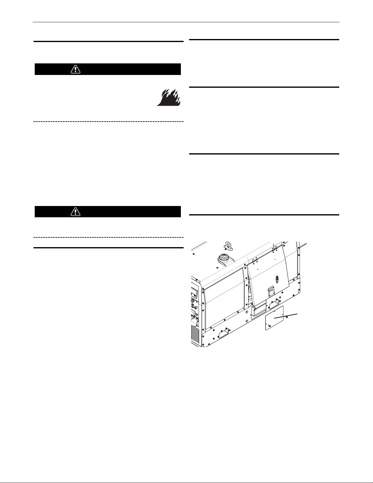
FUEL FILTERS
When working on the fuel system:
• Keep naked lights away, do not smoke!
• Do not spill fuel!
The Dual Maverick®450 is equipped with a Fuel Filter located to
left of air cleaner.The procedure for changing the filter is as
follows.
1. Close the fuel shutoff valve.
2. Clean the area around the fuel filter head. Remove the filter.
Clean the gasket surface of the filter head and replace the oring.
3. Fill the clean filter with clean fuel, and lubricate the o-ring seal
with clean lubricating oil.
4. Install the filter as specified by the filter manufacturer.
Mechanical overtightening will distort the threads, filter
element seal or filter can.
COOLING SYSTEM
The Dual Maverick®450 is equipped with a pressure radiator.
Keep the radiator cap tight to prevent loss of coolant. Clean and
flush the coolant system periodically to prevent clogging the
passage and over-heating the engine. When antifreeze is needed,
always use the permanent type.
• Every 500 hours check radiator to ensure there is no fin
blockage or leaks. Clean as necessary with an environmentally
friendly degreaser and low pressure water.
• When draining the entire contents of the system, remove
radiator cap. Pull drain hose through the battery access door in
the base and open shut off valve until system is empty.
• When refilling, close shut off valve on drain hose.
NAMEPLATES / WARNING DECALS MAINTENANCE
Whenever routine maintenance is performed on this machine - or
at least yearly - inspect all nameplates and labels for legibility.
Replace those which are no longer clear. Refer to the parts list for
the replacement item number.
WELDER / GENERATOR MAINTENANCE
STORAGE
Store the Dual Maverick®450 in clean, dry, protected areas.
CLEANING
Blow out the generator and controls periodically with low pressure
air. Do this at least once a week in particularly dirty areas.
FAN BELT CHANGE
Ensure when changing the fan belt a Lincoln recommended fan
belt is used or equivalent EPDM material, 762 mm datum length
and XPZ profile(Width 10, Height 8 mm, Cogged) belt is used.
Tension new belts to 120lbs, used belts to 80lbs, using a
Burroughs guage. Refer to engine operator's manual for proper
installation and tension.
OIL CHANGE
Remove battery cover (see below) and route oil drain hose through
opening to change engine oil.
WARNING
WARNING
D-3
MAINTENANCEDUAL MAVERICK®450
Remove battery
cover for oil
change.
Page 43

BATTERY HANDLING
GASES FROM BATTERY can explode.
Keep sparks, flame and cigarettes away from
battery.
To prevent EXPLOSION when:
• INSTALLING A NEW BATTERY - disconnect
negative cable from old battery first and
connect to new battery last.
• CONNECTING A BATTERY CHARGER -
Remove battery from welder by disconnecting negative cable first, then positive
cable and battery clamp. When reinstalling, connect
negative cable last. Keep well ventilated.
• USING A BOOSTER - connect positive lead to battery
first then connect negative lead to engine foot.
BATTERY ACID CAN BURN EYES AND SKIN.
• Wear gloves and eye protection and be
careful when working near battery. Follow
instructions printed on battery.
PREVENTING ELECTRICAL DAMAGE
1. When replacing, jumping, or otherwise connecting the battery
to the battery cables, the proper polarity must be observed.
Failure to observe the proper polarity could result in damage
to the charging circuit. The positive (+) battery cable has a
red terminal cover.
2. If the battery requires charging from an external charger,
disconnect the negative battery cable first and then the
positive battery cable before attaching the charger leads.
Failure to do so can result in damage to the internal charger
components. When reconnecting the cables, connect the
positive cable first and the negative cable last.
PREVENTING BATTERY DISCHARGE
Turn the RUN/STOP switch to stop when engine is not running.
PREVENTING BATTERY BUCKLING
Tighten nuts on battery clamp until snug.
CHARGING THE BATTERY
When you charge, jump, replace, or otherwise connect battery
cables to the battery, be sure the polarity is correct. Improper
polarity can damage the charging circuit. The Dual Maverick®450
positive (+) battery terminal has a red terminal cover.
If you need to charge the battery with an external charger,
disconnect the negative cable first, then the positive cable before
you attach the charger leads.
After the battery is charged, reconnect the positive battery cable
first and the negative cable last. Failure to do so can result in
damage to the internal charger components.
Follow the instructions of the battery charger manufacturer for
proper charger settings and charging time.
WARNING
D-4
MAINTENANCEDUAL MAVERICK®450
Page 44

If for any reason you do not understand the test procedures or are unable to perform the tests/repairs safely, contact your
Lincoln Authorized Service Facility for technical troubleshooting assistance before you proceed.
WWW.LINCOLNELECTRIC.COM/LOCATOR
E-1
TROUBLESHOOTINGDUAL MAVERICK®450
TROUBLESHOOTING
How to Use Troubleshooting Guide
Service and Repair should only be performed
by Lincoln Electric Factory Trained
Personnel. Unauthorized repairs performed
on this equipment may result in danger to
the technician and machine operator and will
invalidate your factory warranty. For your safety and to
avoid Electrical Shock, please observe all safety notes and
precautions detailed throughout this manual.
This Troubleshooting Guide is provided to help you locate and
repair possible machine malfunctions. Simply follow the threestep procedure listed below.
Step 1. LOCATE PROBLEM (SYMPTOM).
Look under the column labeled “PROBLEM (SYMPTOMS).” This
column describes possible symptoms that the machine may
exhibit. Find the listing that best describes the symptom that the
machine is exhibiting.
Step 2. POSSIBLE CAUSE.
The second column labeled “POSSIBLE CAUSE” lists the obvious
external possibilities that may contribute to the machine symptom.
Step 3. RECOMMENDED COURSE OF ACTION
This column provides a course of action for the Possible Cause,
generally it states to contact your local Lincoln Authorized Field
Service Facility.
If you do not understand or are unable to perform the
Recommended Course of Action safely, contact your local
Lincoln Authorized Field Service Facility.
E
ELECTRIC SHOCK can kill.
• Turn off machine at the disconnect switch
on the rear of the machine and remove
main power supply connections before
doing any troubleshooting.
WARNING
WARNING
Page 45
If for any reason you do not understand the test procedures or are unable to perform the tests/repairs safely, contact your
Lincoln Authorized Service Facility for technical troubleshooting assistance before you proceed.
WWW.LINCOLNELECTRIC.COM/LOCATOR
Observe all Safety Guidelines detailed throughout this manual
PROBLEMS
(SYMPTOMS)
POSSIBLE
CAUSE
RECOMMENDED
COURSE OF ACTION
E-2
TROUBLESHOOTINGDUAL MAVERICK®450
AUXILIARY OUTPUT
No auxiliary power 1. Check that the circuit breakers did not trip.
If all recommended possible areas of
misadjustment have been checked and the
problem persists, Contact your local Lincoln
Authorized Field Service Facility.
2. Check that the RCD has not reset.
3. Inspect AVR 5 AMP fuse did not blow.
4. Faulty Field Relay(CR3) located under the
right control PC board.
ENGINE
Engine will not crank 1. Low or weak battery.
If all recommended possible areas of
misadjustment have been checked and the
problem persists, Contact your local Lincoln
Authorized Field Service Facility.
2. Inspect for loose or corroded battery
terminals.
3. “Battery circuit” circuit breaker (CB4) has
tripped. Located on upper control panel
beside E-stop button.
4. Faulty starter motor
5. Check starter relay(CR2). Located on left
hand side of fuel tank shield below ECU.
6. E-stop is engaged
Engine will crank but not start 1. Out of fuel.
2. Enter correct security PIN if the PIN function
is enabled.
3. Fuel pump not working
4. Water separator valve closed.
Engine shuts down shortly after starting 1. Low fuel level.
2. Low oil level.
3. Clogged fuel filter. Clean.
4. Faulty oil pressure switch.
Engine has low output or 1. Low fuel
2. Clogged fuel filter
3. Clogged air filter
4. Poor quality fuel – fuel has sat for a long
time.
Engine will not go to low idle 1. Idler switch is in the High Idle position.
2. Aux load might be on
3. Faulty PC board.
Engine does not go to full power when
using auxiliary power.
1. The auxiliary power load is less than 100
Watts. Set the STOP/AUTO/HIGH IDLE
switch to HIGH IDLE.
2. Disconnect / turn off auxiliary power loads
before starting the engine.
Page 46

If for any reason you do not understand the test procedures or are unable to perform the tests/repairs safely, contact your
Lincoln Authorized Service Facility for technical troubleshooting assistance before you proceed.
WWW.LINCOLNELECTRIC.COM/LOCATOR
E-3
TROUBLESHOOTINGDUAL MAVERICK®450
PROBLEMS
(SYMPTOMS)
POSSIBLE
CAUSE
RECOMMENDED
COURSE OF ACTION
WELDING
No weld output 1. Verify the weld output is ON. A green icon with
“Output ON” appears in the upper right corner
of screen whenever weld output is ON.
If all recommended possible areas of
misadjustment have been checked and
the problem persists, Contact your local
Lincoln Authorized Field Service Facility.
2. Verify the work connection is tight and attached
clean base metal.
3. If in CV mode check that “CV TRIGGER
OVERRIDE” is not set to “REMOTE”.
4. Faulty Field Relay(CR3). Located under the right
control pc board.
5. Faulty PC board
No output control – at the front panel 1. Verify the remote control is not turned on.
“Remote ON” appears on the bottom left of
the screen whenever the remote is turned on.
2. Faulty encoder, replace.
No output control – with remote 1. Verify the remote control is not turned on.
“Remote ON” appears on the bottom left of
the screen whenever the remote is turned on.
2. Verify the remote control is turned on. “Remote
ON” appears on the display screen.
Output control range is limited while
using a remote.
1. While in the weld mode, go to the remote screen
and change the scaling of the remote.
The arc is not stable. 1. Verify the polarity of the electrode and work
cables.
2. Cables may be excessively long, undersized or
damaged.
3. Verify the weld settings match the electrode.
Use Ready-Set-Weld, menu for guidance.
VRD (Volts < 30) not showing on the
display
1. Ensure VRD ON/OFF switch on the PCB is
switched to the “RIGHT” to turn VRD “ON”.
2. Faulty 250 ohm resistor (R2 / R1) for loose wire
connection.
3. Faulty PC board.
Operator Selector Switch (SINGLE /
DUAL) is not functioning properly
1. Micro switch inside of polarity switch is bad.
2. Loose wire connection from micro switch in
polarity switch to right side control PC board.
3. Faulty polarity switch.
Wire Feeder does not work when control
cable is connected to 14 pin
connector.
1. Wire Feeder circuit breaker open. Check (42V)
breaker and reset if tripped.
2. Faulty control cable. Repair or replace cable.
3. Faulty wire feeder. Replace wire feeder.
Page 47

If for any reason you do not understand the test procedures or are unable to perform the tests/repairs safely, contact your
Lincoln Authorized Service Facility for technical troubleshooting assistance before you proceed.
WWW.LINCOLNELECTRIC.COM/LOCATOR
TROUBLESHOOTINGDUAL MAVERICK®450
FLASH CODE
NUMBER FAULT
WILL ENGINE
SHUTDOWN? CORRECTIVE ACTION
1
Unit not calibrated Yes ECM requires calibration
2
Excessive engine speed Yes Check over-speed parameter setting
Check electrical interference
Check wiring and connectors
Check ECM ground connections
Check actuator connections and fitment
3
Engine speed unusually
low
Yes Check parameter settings
Check actuator connections and fitment
Check machine loading upon engine
4
Engine protection input
triggered
Yes Check parameter settings
Check Engine protection inputs
Check engine protection run time setinq
5
Factory calibration lost Yes Reload calibration file
Contact distributor
6
Analogue sensor input
out of range
No Check throttle wiring
Recalibrate/Reset throttle settings.
7
Throttle position / IVS
signal mis-match
No - may
restrict
acceleration
Verify wiring on throttle and IVS
Check throttle and IVS parameters
Check throttle configuration
8
ECM failure Yes Check wiring, shielding and ECM
connections. Cycle ignition key. Check
electrical interference.
Consult distributor.
9
Excessive actuator
current limiting
No Check actuator wiring
Check actuator fitment
Check parameter settings
10
No engine speed signal Yes - non
start
Check speed pick up fitment
Check speed pick up wiring
Check electrical interference on pick up
sensor and wiring.
Check contamination on sensor
11
Autocrank detects engine
non start
No Check wiring and settings.
Check engine mechanicals
12
Excessive current draw
on Auxiliary output
No Check wiring to output
Check current draw of lamp, relay etc.
13
Excessive current draw
on Auxiliary2 output
No Check wiring to output
Check current draw of lamp, relay etc.
14
Actuator disconnected or
open circuit
Yes Check actuator wiring and fitment
Check electrical interference
Check actuator resistance
(less than 10 ohms)
ENGINE FAULT FLASH CODES ON ECG
Page 48

F-1
WIRING DIAGRAMDUAL MAVERICK®450
NOTE: This diagram is for reference only. It may not be accurate for all machines covered by this manual. The specific diagram for a particular code is included
with the machine. If the diagram is illegible, write to the Service Department for a replacement. Give the equipment code number.
BU
4
BK
GY
WH
1
GY
1
4
2
WH
START BUTTON
4B
77B
21
2B
75B
GND-A
76B
115VAC
CONTACTOR
WORK
42VAC
GROUND
AMPHENO L 1
J
A
D
CHB
K
EFG
I
R
ALL CASE FRONT COM PONENTS SHOWN VIE WED FROM R EAR
B2-POS
B4-NEG
B5-POS
B1-NEG
CHOPPER
PCB3
B6
B5
B4
B1
B2
B3
B8
B7
DUAL MAVERICK 450 WIRING DIAGRAM
L1 CHOKE
REMOTE
CONTROL
SENSOR
FUEL LVL.
WK
235
5J
229
228
241
G
SWITCH
SWITCH
OIL PRESS URE
SENSOR & SWITCH
COOLANT TEMPERATURE
SENSOR & SWITCH
SHOWN IN
"RUN"/"HIGH"
POSITI ON
ELECTRIC AL SYMBOLS PER E1537
ENGINE
SUPPORT
ON BASE
ENGINE BLOCK
12V
BATTERY
-
+
STARTING
MOTOR
STARTER
SOLENOID
ALTERNATOR
GLOW PLUG
BUTTON
GLOW
PLUGS
+
-
13A
R1
206C
POS-STUD
POS-S TUD
SENSOR
SENSOR
208A
SWITCH CO NTACTS
SHOWN IN "+" POSITION
WIRE FEEDER
VOLTMETE R
SWITCH
A.19
G9020PRINT
EMERGENCY
STOP
CB2
CB3
7
L1L2
12
L3
15A
15A
NA
E
NA
E
E
N
L1
L2
L3
2B
2C
2A
RCD
40A
5A B
5A
5D
220 V
1 PHASE
(BLUE)
380 V
3 PHASE
(RED)
206A
208A
208C
WELDING OUTPUT
TERMINAL
WELDING OUTPUT
TERMINAL
I
+
208
GROUND STUD ON
AUXILI ARY POWER
RECEPTAC LE PANEL
T2
T3
T1
TERMINAL BLOCK ON
LOWER CONT ROL PANEL
TOP LEFT
CONTROL
PCB 1
X1
X2
X3
D1
RECTIFIER BRIDGE
STATOR
WELD 1
WINDI NGS
206B
B3 CHOKE
206A
4BR
77BR
2BR
75BR
GND-AR
41R
42AR
76BR
115VAC
CONTACTOR
WORK
42VAC
GROUND
AMPHENOL 1
J
A
D
CHB
K
E
F
G
I
2BR
GND-BR
ABC
D
E
F
76BR
75BR
AMPHENOL 2
77BR
B4-NEG
B5-POS
B1-NEG
B2-POS
CHOPPER
PCB4
B3
B2
B1
B4
B5
B6
B7
B8
L2 CHOKE
REMOTE
CONTROL
REMOTE
CONTROL
CONTACTOR
GROUND
+
-
POS-STUD
POS-S TUD
B3 CHOKE
SWITCH CO NTACTS
SHOWN IN "+" POSITION
WIRE FEED ER
VOLTMETER
SWITCH
I
+
CONTROL
PCB 2
Y1
Y2
Y3
D2
RECTIFIER BRIDGE
STATOR
WELD 2
WINDI NGS
206AR
14
23
25
23R
25R
WELDING OUTPUT
TERMINAL
11
220 V
1 PHASE
(BLUE)
15
15
14R
SW1
WHITE
TOROID
BLACK
ROTOR
EXCITER
FIELD
BLACK
W
U
V
2C
ABC
SPEED
SENSOR
+
-
ACTUATOR
+
-
233
5G
57
57N
58
58N
66
GND-A
GND-K
B+
234
86
5432
1
12
111098
7
6
12
1
2
11 10
34
98
5
6
7
ENGINE
CONTROLLER
ECG
J1 (GREY) J2 (BLACK )
L
IG
233A
NO NC
GROUND STUD RI GHT
UPPER CONT ROL PANEL
GND-B
ON / IDLER CONTROL /
STOP SWITCH
1
5
2
3
6
8
7
+
-
239
844
5J
AC
200A
POWER RELAY
232T
832
4
BC
A0
1
+
238C
232Z
231
231
378
232L
GND-T
GND-Z
206DR
COM
NO
232T
21R
41
42A
C
A
5H
GND-P
GND-AR
GND-BR
5H
GND-X
2B
GND-B
ABC
D
F
76B
75B
AMPHENO L 2
77A
77B
REMOTE
CONTROL
CONTACTOR
GROUND
4BE
AVR BL4-U
AUXN
AUXL
0
+EX
-EX
230
115
EXT POT
GLOW
PLUGS
LCD
DISPLAY LEFT
WH
GY
CONTROL
BOARD LEFT
CONTROL
BOARD RIGHT
41R
42AR
5E
5E
5D
5E
5C
200
U4
W4
V4
V2
V1
200
EMC
FILTER
AUX-L
400V 3PH
CB1
25A
STUD BESIDE STATOR FOOT
2
3
5
BU
BK
BYPASS
FILTER
ASSEMB LY
2
4
76A
75A
77AR
2R
4R
75AR
76AR
821
GND-X
+
-
400
EMC-N
SINGLE/
DUAL
SW1
208
G9022- 1
14
15
208C
2
75A
77A
BK
BU
B1
W1
R1GYU1
Y1
WH
G1
76A
4
J2
AMP776230
1
13
24
23
12
35
J1
832
86
52A
66
229
GND-Z
232
92TR
92TL
23
25
25FT
23FT
844
615
232K
285
WHITE
BLACK
AMP776200
1
8
9
15
16
23
1
-
2
20
9G
J1
228
241
92TL
92TR
23FT
25FT
378
615
23R
25R
232L
GND-T
AMP776200
1
8
9
15
16
23
14R
206DR
75AR
77AR
2R
4R
76AR
2J
AMP776230
1
13
24
23
12
35
BK
BU
B2
W2
R2GYU2
Y2
WH
G2
208CR
J3
J3
206D
LCD
DISPLAY RI GHT
3
5
BUBK
BU
GY
WH
JP1
208AR
21
238A
5G
42VAC
WINDI NGS
41C
400
VRD
OFF
ON
VRD
OFF ON
236A
236
238D
236A
+
85
30
A
7
8
86
CR2
7
8
377
377
285
52A
238A
237
NC
NC
821
NC
NC
L3 L2
L1
7E
2B
232
13B
238
232K
238B
4BR
B6 CHOKE
Connection Point
on Chopper Panel
Connection Point
on Chopper Panel
Connection Point
on Chopper Panel
Connection
Point on
Chopper Panel
233
233A
233B
RED
234
5
208C
206B
WELDING OUTPUT
TERMINAL
BYPASS
FILTER
ASSEMB LY
2A
5A
ENCODER
65432
1
V
BLACK
BLUE
GREEN
YELLOW
WHITE
RED
ENCODER
65432
1
V
BLACK
BLUE
GREEN
YELLOW
WHITE
RED
GND IN HIG H
VOLTAGE BOX
CB5
10A
42AR
42A
41
41R
208AR
21R
BK
208C
5C
GND-C 5GND-E
GND-E
GND-DGND-D
206AR
R2
13BR
13AR
42C
85
30
A
7
8
86
CR1
7
8
CR3
16
J1
P1
W1
Y1
G1 U1 B1
R1
16
J2
P2
W2 Y2 G2 U2 B2R2
232Z
W2
W3
U2
U3
V3
U1
W1
AUXIL IARY
WINDING
B
207
207R
207
B6 CHOKE
207R
C
A
208CR
206C
Page 49

5.75
146
9.90
251.5
27.04
686.8
30.04
763
28.86
732.9
36.08
916.4
39.09
992.9
31.04
788.5
22.44
570
65.00
1651
43.07
1093.9
59.50
1511.3
33.40
848.3
F-2
DIMENSION PRINTDUAL MAVERICK®450
Page 50

WARNING
panish
S
AVISO DE
PRECAUCION
French
ATTENTION
erman
G
WARNUNG
ortuguese
P
ATENÇÃO
Japanese
Chinese
l Do not touch electrically live parts or
electrode with skin or wet clothing.
l Insulate yourself from work and
ground.
l
No toque las partes o los electrodos
bajo carga con la piel o ropa mojada.
l Aislese del trabajo y de la tierra.
l Ne laissez ni la peau ni des vête-
ments mouillés entrer en contact
avec des pièces sous tension.
l
Isolez-vous du travail et de la terre.
l Berühren Sie keine stromführenden
Teile oder Elektroden mit Ihrem
Körper oder feuchter Kleidung!
l Isolieren Sie sich von den
Elektroden und dem Erdboden!
l Não toque partes elétricas e elec-
trodos com a pele ou roupa molhada.
l
Isole-se da peça e terra.
l Keep flammable materials away.
l
Mantenga el material combustible
fuera del área de trabajo.
l
Gardez à l’écart de tout matériel
inflammable.
l Entfernen Sie brennbarres Material!
l
Mantenha inflamáveis bem guardados.
l Wear eye, ear and body protection.
l
Protéjase los ojos, los oídos y el
cuerpo.
l
Protégez vos yeux, vos oreilles et
votre corps.
l Tragen Sie Augen-, Ohren- und Kör-
perschutz!
l
Use proteção para a vista, ouvido e
corpo.
Korean
Arabic
READ AND UNDERSTAND THE MANUFACTURER’S INSTRUCTION FOR THIS EQUIPMENT AND THE CONSUMABLES TO BE
USED AND FOLLOW YOUR EMPLOYER’S SAFETY PRACTICES.
SE RECOMIENDA LEER Y ENTENDER LAS INSTRUCCIONES DEL FABRICANTE PARA EL USO DE ESTE EQUIPO Y LOS
CONSUMIBLES QUE VA A UTILIZAR, SIGA LAS MEDIDAS DE SEGURIDAD DE SU SUPERVISOR.
LISEZ ET COMPRENEZ LES INSTRUCTIONS DU FABRICANT EN CE QUI REGARDE CET EQUIPMENT ET LES PRODUITS A
ETRE EMPLOYES ET SUIVEZ LES PROCEDURES DE SECURITE DE VOTRE EMPLOYEUR.
LESEN SIE UND BEFOLGEN SIE DIE BETRIEBSANLEITUNG DER ANLAGE UND DEN ELEKTRODENEINSATZ DES HERSTELLERS. DIE UNFALLVERHÜTUNGSVORSCHRIFTEN DES ARBEITGEBERS SIND EBENFALLS ZU BEACHTEN.
Page 51

l Keep your head out of fumes.
l Use ventilation or exhaust to
remove fumes from breathing zone.
l Turn power off before servicing.
l Do not operate with panel open or
guards off.
WARNING
l Los humos fuera de la zona de res-
piración.
l Mantenga la cabeza fuera de los
humos. Utilice ventilación o
aspiración para gases.
l Gardez la tête à l’écart des fumées.
l Utilisez un ventilateur ou un aspira-
teur pour ôter les fumées des zones
de travail.
l
Vermeiden Sie das Einatmen von
Schweibrauch!
l Sorgen Sie für gute Be- und
Entlüftung des Arbeitsplatzes!
l Mantenha seu rosto da fumaça.
l Use ventilação e exhaustão para
remover fumo da zona respiratória.
l Desconectar el cable de ali-
mentación de poder de la máquina
antes de iniciar cualquier servicio.
l Débranchez le courant avant l’entre-
tien.
l
Strom vor Wartungsarbeiten
abschalten! (Netzstrom völlig öffnen; Maschine anhalten!)
l Não opere com as tampas removidas.
l Desligue a corrente antes de fazer
serviço.
l
Não toque as partes elétricas nuas.
l No operar con panel abierto o
guardas quitadas.
l N’opérez pas avec les panneaux
ouverts ou avec les dispositifs de
protection enlevés.
l
Anlage nie ohne Schutzgehäuse
oder Innenschutzverkleidung in
Betrieb setzen!
l
Mantenha-se afastado das partes
moventes.
l Não opere com os paineis abertos
ou guardas removidas.
Spanish
AVISO DE
PRECAUCION
rench
F
ATTENTION
German
WARNUNG
ortuguese
P
ATENÇÃO
Japanese
Chinese
Korean
Arabic
LEIA E COMPREENDA AS INSTRUÇÕES DO FABRICANTE PARA ESTE EQUIPAMENTO E AS PARTES DE USO, E SIGA AS
PRÁTICAS DE SEGURANÇA DO EMPREGADOR.
Page 52

CUSTOMER ASSISTANCE POLICY
The business of The Lincoln Electric Company is manufacturing
and selling high quality welding equipment, consumables, and
cutting equipment. Our challenge is to meet the needs of our
customers and to exceed their expectations. On occasion,
purchasers may ask Lincoln Electric for advice or information
about their use of our products. We respond to our customers
based on the best information in our possession at that time.
Lincoln Electric is not in a position to warrant or guarantee such
advice, and assumes no liability, with respect to such information
or advice. We expressly disclaim any warranty of any kind,
including any warranty of fitness for any customer’s particular
purpose, with respect to such information or advice. As a matter
of practical consideration, we also cannot assume any responsibility for updating or correcting any such information or advice
once it has been given, nor does the provision of information or
advice create, expand or alter any warranty with respect to the
sale of our products.
Lincoln Electric is a responsive manufacturer, but the selection
and use of specific products sold by Lincoln Electric is solely
within the control of, and remains the sole responsibility of the
customer. Many variables beyond the control of Lincoln Electric
affect the results obtained in applying these types of fabrication
methods and service requirements.
Subject to Change – This information is accurate to the best of our
knowledge at the time of printing. Please refer to
www.lincolnelectric.com for any updated information.
 Loading...