

Lincoln Electric DOWNFLEX 200, DOWNFLEX 400 Instruction Manual
DOWNFLEX 200/400
IM10013
1RYHPEHU, 2011
For use with machines having Code Numbers:
Safety Depends on You
Lincoln arc welding and cutting
equipment is designed and built
with safety in mind. However,
your overall safety can be
increased by proper installation
... and thoughtful operation on
your part. DO NOT INSTALL,
OPERATE OR REPAIR THIS
EQUIPMENT WITHOUT READING THIS MANUAL AND THE
SAFETY PRECAUTIONS CONTAINED THROUGHOUT. And,
most importantly, think before
you act and be careful.
K2751-2, K2751-3, K2751-4,
CK 2751-2, CK 2751-3, CK 2751-4,
CK 2751-25, CK 2751-35
INSTRUCTION MANUAL
Copyright © Lincoln Global Inc.
• World's Leader in Welding and Cutting Products •
• Sales and Service through Subsidiaries and Distributors Worldwide •
Cleveland, Ohio 44117-1199 U.S.A. TEL: 888.935.3878 FAX: 216.383.8823 WEB SITE: www.lincolnelectric.com
i
SAFETY
i
WARNING
CALIFORNIA PROPOSITION 65 WARNINGS
Diesel engine exhaust and some of its constituents
are known to the State of California to cause cancer, birth defects, and other reproductive harm.
The Above For Diesel Engines
ARC WELDING CAN BE HAZARDOUS. PROTECT YOURSELF AND OTHERS FROM POSSIBLE SERIOUS INJURY OR DEATH.
KEEP CHILDREN AWAY. PACEMAKER WEARERS SHOULD CONSULT WITH THEIR DOCTOR BEFORE OPERATING.
Read and understand the following safety highlights. For additional safety information, it is strongly recommended that you
purchase a copy of “Safety in Welding & Cutting - ANSI Standard Z49.1” from the American Welding Society, P.O. Box
351040, Miami, Florida 33135 or CSA Standard W117.2-1974. A Free copy of “Arc Welding Safety” booklet E205 is available
from the Lincoln Electric Company, 22801 St. Clair Avenue, Cleveland, Ohio 44117-1199.
BE SURE THAT ALL INSTALLATION, OPERATION, MAINTENANCE AND REPAIR PROCEDURES ARE
PERFORMED ONLY BY QUALIFIED INDIVIDUALS.
The engine exhaust from this product contains
chemicals known to the State of California to cause
cancer, birth defects, or other reproductive harm.
The Above For Gasoline Engines
FOR ENGINE
powered equipment.
1.a. Turn the engine off before troubleshooting and maintenance
work unless the maintenance work requires it to be running.
____________________________________________________
1.b. Operate engines in open, well-ventilated
areas or vent the engine exhaust fumes
outdoors.
____________________________________________________
1.c. Do not add the fuel near an open flame welding arc or when the engine is running. Stop
the engine and allow it to cool before refueling to prevent spilled fuel from vaporizing on
contact with hot engine parts and igniting. Do
not spill fuel when filling tank. If fuel is spilled,
wipe it up and do not start engine until fumes
have been eliminated.
____________________________________________________
1.d. Keep all equipment safety guards, covers and devices in position and in good repair.Keep hands, hair, clothing and tools
away from V-belts, gears, fans and all other moving parts
when starting, operating or repairing equipment.
____________________________________________________
1.e. In some cases it may be necessary to remove safety
guards to perform required maintenance. Remove
guards only when necessary and replace them when the
maintenance requiring their removal is complete.
Always use the greatest care when working near moving
parts.
___________________________________________________
1.f. Do not put your hands near the engine fan.
Do not attempt to override the governor or
idler by pushing on the throttle control rods
while the engine is running.
1.h. To avoid scalding, do not remove the
radiator pressure cap when the engine is
hot.
ELECTRIC AND
MAGNETIC FIELDS
may be dangerous
2.a. Electric current flowing through any conductor causes
localized Electric and Magnetic Fields (EMF). Welding
current creates EMF fields around welding cables and
welding machines
2.b. EMF fields may interfere with some pacemakers, and
welders having a pacemaker should consult their physician
before welding.
2.c. Exposure to EMF fields in welding may have other health
effects which are now not known.
2.d. All welders should use the following procedures in order to
minimize exposure to EMF fields from the welding circuit:
2.d.1.
Route the electrode and work cables together - Secure
them with tape when possible.
2.d.2. Never coil the electrode lead around your body.
2.d.3. Do not place your body between the electrode and
work cables. If the electrode cable is on your right
side, the work cable should also be on your right side.
___________________________________________________
1.g. To prevent accidentally starting gasoline engines while
turning the engine or welding generator during maintenance
work, disconnect the spark plug wires, distributor cap or
magneto wire as appropriate.
DOWNFLEX 200/400
2.d.4. Connect the work cable to the workpiece as close as
possible to the area being welded.
2.d.5. Do not work next to welding power source.
ii
SAFETY
ii
ELECTRIC SHOCK can kill.
3.a. The electrode and work (or ground) circuits
are electrically “hot” when the welder is on.
Do not touch these “hot” parts with your bare
skin or wet clothing. Wear dry, hole-free
gloves to insulate hands.
3.b. Insulate yourself from work and ground using dry insulation.
Make certain the insulation is large enough to cover your full
area of physical contact with work and ground.
In addition to the normal safety precautions, if welding
must be performed under electrically hazardous
conditions (in damp locations or while wearing wet
clothing; on metal structures such as floors, gratings or
scaffolds; when in cramped positions such as sitting,
kneeling or lying, if there is a high risk of unavoidable or
accidental contact with the workpiece or ground) use
the following equipment:
• Semiautomatic DC Constant Voltage (Wire) Welder.
• DC Manual (Stick) Welder.
• AC Welder with Reduced Voltage Control.
3.c. In semiautomatic or automatic wire welding, the electrode,
electrode reel, welding head, nozzle or semiautomatic
welding gun are also electrically “hot”.
3.d. Always be sure the work cable makes a good electrical
connection with the metal being welded. The connection
should be as close as possible to the area being welded.
3.e. Ground the work or metal to be welded to a good electrical
(earth) ground.
3.f.
Maintain the electrode holder, work clamp, welding cable and
welding machine in good, safe operating condition. Replace
damaged insulation.
3.g. Never dip the electrode in water for cooling.
3.h. Never simultaneously touch electrically “hot” parts of
electrode holders connected to two welders because voltage
between the two can be the total of the open circuit voltage
of both welders.
3.i. When working above floor level, use a safety belt to protect
yourself from a fall should you get a shock.
3.j. Also see Items 6.c. and 8.
ARC RAYS can burn.
4.a. Use a shield with the proper filter and cover
plates to protect your eyes from sparks and
the rays of the arc when welding or observing
open arc welding. Headshield and filter lens
should conform to ANSI Z87. I standards.
4.b. Use suitable clothing made from durable flame-resistant
material to protect your skin and that of your helpers from
the arc rays.
4.c. Protect other nearby personnel with suitable, non-flammable
screening and/or warn them not to watch the arc nor expose
themselves to the arc rays or to hot spatter or metal.
FUMES AND GASES
can be dangerous.
5.a. Welding may produce fumes and gases
hazardous to health. Avoid breathing these
fumes and gases. When welding, keep
your head out of the fume. Use enough
ventilation and/or exhaust at the arc to keep
fumes and gases away from the breathing zone. When
welding with electrodes which require special
ventilation such as stainless or hard facing (see
instructions on container or MSDS) or on lead or
cadmium plated steel and other metals or coatings
which produce highly toxic fumes, keep exposure as
low as possible and within applicable OSHA PEL and
ACGIH TLV limits using local exhaust or mechanical ventilation. In confined spaces or in some circumstances,
outdoors, a respirator may be required. Additional precautions are also required when welding on galvanized
steel.
5. b. The operation of welding fume control equipment is affected
by various factors including proper use and positioning of the
equipment, maintenance of the equipment and the specific
welding procedure and application involved. Worker exposure level should be checked upon installation and periodically thereafter to be certain it is within applicable OSHA
PEL and ACGIH TLV limits.
5.c.
Do not weld in locations near chlorinated hydrocarbon
coming from degreasing, cleaning or spraying operations.
The heat and rays of the arc can react with solvent vapors
form phosgene, a highly toxic gas, and other irritating products.
vapors
to
5.d. Shielding gases used for arc welding can displace air and
cause injury or death. Always use enough ventilation,
especially in confined areas, to insure breathing air is safe.
5.e. Read and understand the manufacturerʼs instructions for this
equipment and the consumables to be used, including the
material safety data sheet (MSDS) and follow your
employerʼs safety practices. MSDS forms are available from
your welding distributor or from the manufacturer.
5.f. Also see item 1.b.
DOWNFLEX 200/400
iii
SAFETY
iii
WELDING and CUTTING
SPARKS can
cause fire or explosion.
6.a.
Remove fire hazards from the welding area.
If this is not possible, cover them to prevent
Remember that welding sparks and hot
materials from welding can easily go through small cracks
and openings to adjacent areas. Avoid welding near
hydraulic lines. Have a fire extinguisher readily available.
6.b. Where compressed gases are to be used at the job site,
special precautions should be used to prevent hazardous
situations. Refer to “Safety in Welding and Cutting” (ANSI
Standard Z49.1) and the operating information for the
equipment being used.
6.c. When not welding, make certain no part of the electrode
circuit is touching the work or ground. Accidental contact can
cause overheating and create a fire hazard.
6.d. Do not heat, cut or weld tanks, drums or containers until the
proper steps have been taken to insure that such procedures
will not cause flammable or toxic vapors from substances
inside. They can cause an explosion even
been “cleaned”. For information, purchase “Recommended
Safe Practices for the
Containers and Piping That Have Held Hazardous
Substances”, AWS F4.1 from the American Welding Society
(see address above).
6.e. Vent hollow castings or containers before heating, cutting or
welding. They may explode.
Sparks and spatter are thrown from the welding arc. Wear oil
6.f.
free protective garments such as leather gloves, heavy shirt,
cuffless trousers, high shoes and a cap over your hair. Wear
ear plugs when welding out of position or in confined places.
Always wear safety glasses with side shields when in a
welding area.
6.g. Connect the work cable to the work as close to the welding
area as practical. Work cables connected to the building
framework or other locations away from the welding area
increase the possibility of the welding current passing
through lifting chains, crane cables or other alternate circuits.
This can create fire hazards or overheat lifting chains or
cables until they fail.
6.h. Also see item 1.c.
the welding sparks from starting a fire.
though
they have
Preparation
for Welding and Cutting of
CYLINDER may explode
if damaged.
7.a. Use only compressed gas cylinders
containing the correct shielding gas for the
process used and properly operating
regulators designed for the gas and
pressure used. All hoses, fittings, etc. should be suitable for
the application and maintained in good condition.
7.b. Always keep cylinders in an upright position securely
chained to an undercarriage or fixed support.
7.c. Cylinders should be located:
• Away from areas where they may be struck or subjected to
physical damage.
• A safe distance from arc welding or cutting operations and
any other source of heat, sparks, or flame.
7.d. Never allow the electrode, electrode holder or any other
electrically “hot” parts to touch a cylinder.
7.e. Keep your head and face away from the cylinder valve outlet
when opening the cylinder valve.
7.f. Valve protection caps should always be in place and hand
tight except when the cylinder is in use or connected for
use.
7.g. Read and follow the instructions on compressed gas
cylinders, associated equipment, and CGA publication P-l,
“Precautions for Safe Handling of Compressed Gases in
Cylinders,” available from the Compressed Gas Association
1235 Jefferson Davis Highway, Arlington, VA 22202.
FOR ELECTRICALLY
powered equipment.
8.a. Turn off input power using the disconnect
switch at the fuse box before working on
the equipment.
8.b. Install equipment in accordance with the U.S. National
Electrical Code, all local codes and the manufacturerʼs
recommendations.
8.c. Ground the equipment in accordance with the U.S. National
Electrical Code and the manufacturerʼs recommendations.
6.I. Read and follow NFPA 51B “ Standard for Fire Prevention
During Welding, Cutting and Other Hot Work”, available from
NFPA, 1 Batterymarch Park, PO box 9101, Quincy, Ma
022690-9101.
6.j. Do not use a welding power source for pipe thawing.
Refer to http://www.lincolnelectric.com/safety for additional safety information.
DOWNFLEX 200/400

iv
SAFETY
iv
PRÉCAUTIONS DE SÛRETÉ
Pour votre propre protection lire et observer toutes les instructions
et les précautions de sûreté specifiques qui parraissent dans ce
manuel aussi bien que les précautions de sûreté générales suivantes:
Sûreté Pour Soudage A LʼArc
1. Protegez-vous contre la secousse électrique:
a. Les circuits à lʼélectrode et à la piéce sont sous tension
quand la machine à souder est en marche. Eviter toujours
tout contact entre les parties sous tension et la peau nue
ou les vétements mouillés. Porter des gants secs et sans
trous pour isoler les mains.
b. Faire trés attention de bien sʼisoler de la masse quand on
soude dans des endroits humides, ou sur un plancher metallique ou des grilles metalliques, principalement dans
les positions assis ou couché pour lesquelles une grande
partie du corps peut être en contact avec la masse.
c. Maintenir le porte-électrode, la pince de masse, le câble de
soudage et la machine à souder en bon et sûr état defonctionnement.
d.Ne jamais plonger le porte-électrode dans lʼeau pour le
refroidir.
e. Ne jamais toucher simultanément les parties sous tension
des porte-électrodes connectés à deux machines à souder
parce que la tension entre les deux pinces peut être le total
de la tension à vide des deux machines.
f. Si on utilise la machine à souder comme une source de
courant pour soudage semi-automatique, ces precautions
pour le porte-électrode sʼapplicuent aussi au pistolet de
soudage.
2. Dans le cas de travail au dessus du niveau du sol, se protéger
contre les chutes dans le cas ou on recoit un choc. Ne jamais
enrouler le câble-électrode autour de nʼimporte quelle partie du
corps.
5. Toujours porter des lunettes de sécurité dans la zone de
soudage. Utiliser des lunettes avec écrans lateraux dans les
zones où lʼon pique le laitier.
6. Eloigner les matériaux inflammables ou les recouvrir afin de
prévenir tout risque dʼincendie dû aux étincelles.
7. Quand on ne soude pas, poser la pince à une endroit isolé de
la masse. Un court-circuit accidental peut provoquer un
échauffement et un risque dʼincendie.
8. Sʼassurer que la masse est connectée le plus prés possible de
la zone de travail quʼil est pratique de le faire. Si on place la
masse sur la charpente de la construction ou dʼautres endroits
éloignés de la zone de travail, on augmente le risque de voir
passer le courant de soudage par les chaines de levage,
câbles de grue, ou autres circuits. Cela peut provoquer des
risques dʼincendie ou dʼechauffement des chaines et des
câbles jusquʼà ce quʼils se rompent.
9. Assurer une ventilation suffisante dans la zone de soudage.
Ceci est particuliérement important pour le soudage de tôles
galvanisées plombées, ou cadmiées ou tout autre métal qui
produit des fumeés toxiques.
10. Ne pas souder en présence de vapeurs de chlore provenant
dʼopérations de dégraissage, nettoyage ou pistolage. La
chaleur ou les rayons de lʼarc peuvent réagir avec les vapeurs
du solvant pour produire du phosgéne (gas fortement toxique)
ou autres produits irritants.
11. Pour obtenir de plus amples renseignements sur la sûreté, voir
le code “Code for safety in welding and cutting” CSA Standard
W 117.2-1974.
PRÉCAUTIONS DE SÛRETÉ POUR
3. Un coup dʼarc peut être plus sévère quʼun coup de soliel, donc:
a. Utiliser un bon masque avec un verre filtrant approprié ainsi
quʼun verre blanc afin de se protéger les yeux du rayonnement de lʼarc et des projections quand on soude ou
quand on regarde lʼarc.
b. Porter des vêtements convenables afin de protéger la peau
de soudeur et des aides contre le rayonnement de lʻarc.
c. Protéger lʼautre personnel travaillant à proximité au
soudage à lʼaide dʼécrans appropriés et non-inflammables.
4. Des gouttes de laitier en fusion sont émises de lʼarc de
soudage. Se protéger avec des vêtements de protection libres
de lʼhuile, tels que les gants en cuir, chemise épaisse, pantalons sans revers, et chaussures montantes.
DOWNFLEX 200/400
LES MACHINES À SOUDER À
TRANSFORMATEUR ET À
REDRESSEUR
1. Relier à la terre le chassis du poste conformement au code de
lʼélectricité et aux recommendations du fabricant. Le dispositif
de montage ou la piece à souder doit être branché à une
bonne mise à la terre.
2. Autant que possible, Iʼinstallation et lʼentretien du poste seront
effectués par un électricien qualifié.
3. Avant de faires des travaux à lʼinterieur de poste, la debrancher à lʼinterrupteur à la boite de fusibles.
4. Garder tous les couvercles et dispositifs de sûreté à leur place.

Thank You
vv
for selecting a QUALITY product by Lincoln Electric. We want you
to take pride in operating this Lincoln Electric Company product •••
as much pride as we have in bringing this product to you!
The business of The Lincoln Electric Company is manufacturing and selling high quality welding equipment, consumables, and cutting equipment. Our challenge is to meet the needs of our customers and to exceed their expectations. On occasion, purchasers may ask Lincoln Electric
for advice or information about their use of our products. We respond to our customers based on the best information in our possession at that
time. Lincoln Electric is not in a position to warrant or guarantee such advice, and assumes no liability, with respect to such information or
advice. We expressly disclaim any warranty of any kind, including any warranty of fitness for any customerʼs particular purpose, with respect
to such information or advice. As a matter of practical consideration, we also cannot assume any responsibility for updating or correcting any
such information or advice once it has been given, nor does the provision of information or advice create, expand or alter any warranty with
respect to the sale of our products.
Lincoln Electric is a responsive manufacturer, but the selection and use of specific products sold by Lincoln Electric is solely within the control
of, and remains the sole responsibility of the customer. Many variables beyond the control of Lincoln Electric affect the results obtained in
applying these types of fabrication methods and service requirements.
Subject to Change – This information is accurate to the best of our knowledge at the time of printing. Please refer to www.lincolnelectric.com
for any updated information.
CUSTOMER ASSISTANCE POLICY
Please Examine Carton and Equipment For Damage Immediately
When this equipment is shipped, title passes to the purchaser upon receipt by the carrier. Consequently, Claims
for material damaged in shipment must be made by the purchaser against the transportation company at the time
the shipment is received.
Please record your equipment identification information below for future reference. This information can be found
on your machine nameplate.
Product _________________________________________________________________________________
Model Number ___________________________________________________________________________
Code Number or Date Code_________________________________________________________________
Serial Number____________________________________________________________________________
Date Purchased___________________________________________________________________________
Where Purchased_________________________________________________________________________
Whenever you request replacement parts or information on this equipment, always supply the information you
have recorded above. The code number is especially important when identifying the correct replacement parts.
On-Line Product Registration
- Register your machine with Lincoln Electric either via fax or over the Internet.
• For faxing: Complete the form on the back of the warranty statement included in the literature packet
accompanying this machine and fax the form per the instructions printed on it.
• For On-Line Registration: Go to our
Your Product”. Please complete the form and submit your registration.
Read this Operators Manual completely before attempting to use this equipment. Save this manual and keep it
handy for quick reference. Pay particular attention to the safety instructions we have provided for your protection.
The level of seriousness to be applied to each is explained below:
WEB SITE at www.lincolnelectric.com. Choose “Support” and then “Register
WARNING
This statement appears where the information must be followed exactly to avoid serious personal injury or loss of life.
CAUTION
This statement appears where the information must be followed to avoid minor personal injury or damage to this equipment.

TABLE OF CONTENTS
Page
Installation.......................................................................................................................Section A
Technical Specifications.......................................................................................................A-1
General Description..............................................................................................................A-2
Intended Use ........................................................................................................................A-2
Components .........................................................................................................................A-2
Installation......................................................................................................................A-3/A-5
Installation Of Remaining Options .................................................................................A-5/A-8
Electrical Connection............................................................................................................A-9
Connection To The Input Power ........................................................................................A-10
Direction Of Rotation..........................................................................................................A-11
Operation.........................................................................................................................Section B
General Description..............................................................................................................B-1
Operation..............................................................................................................................B-1
Safety Precautions ...............................................................................................................B-1
Filter Replacement ...............................................................................................................B-3
Downflex 200-M (Only) ........................................................................................................B-5
Downflex 400-MS (Only) ......................................................................................................B-6
Downflex 400-MS/A (Only)...................................................................................................B-7
Accessories.....................................................................................................Section C
Options / Accessories............................................................................................C-1
vivi
Maintenance....................................................................................................................Section D
Safety Precautions ...............................................................................................................D-1
Maintenance.........................................................................................................................D-1
Periodic Maintenance...........................................................................................................D-2
Disposal ...............................................................................................................................D-2
Troubleshooting .............................................................................................................Section E
How To Use Troubleshooting Guide....................................................................................E-1
Troubleshooting Guide ..................................................................................................E-2/E-4
Wiring Diagrams.............................................................................................................Section D
Downflex 200-M .............................................................................................................F-1/F-3
208-240V/3~/60Hz (USA) .............................................................................................F-1
480V/3~/60Hz (USA).....................................................................................................F-2
600V/3~/60Hz (CANADA) .............................................................................................F-3
Downflex 400-MS...........................................................................................................F-4/F-6
208-240/3~/60Hz (USA)................................................................................................F-4
480V/3~/60Hz (USA).....................................................................................................F-5
600V/3~/60Hz (USA).....................................................................................................F-6
Downflex 400-MS/A .......................................................................................................F-7/F-9
208-240V/3~/60Hz (USA) .............................................................................................F-7
480V/3~/60Hz (USA).....................................................................................................F-8
600V/3~/60Hz (USA).....................................................................................................F-9
Parts ..................................................................................................................................P-
A-1
INSTALLATION
TECHNICAL SPECIFICATIONS - DOWNFLEX 200/400
DIMENSIONS L x W x H
Downdraft Table 54.3 x 39.4 x 36.2 in. (1380 x 1005 x 920 mm)
Downdraft Table incl. Backdraft Kit and Side Panels 54.3 x 39.4 x 60.8 in. (1380 x 1005 x 1543 mm)
HEIGHT ADJUSTMENT
36 - 38 in. / 920 - 970 mm (in case of wheel kit: fixed working height 37.4 in. / 950 mm)
WEIGHT (Without Backdraft Kit, Side Panels And Other Options)
DownFlex 200-M 540 lbs. (245 kg)
DownFlex 400-MS 562 lbs. (255 kg)
DownFlex 400-MS/A 562 lbs. (255 kg)
MAXIMUM LOAD
440 lbs. (200 kg) (In Case Of Wheel Kit: 330 lbs. (150kg))
CONNECTION VOLTAGE
USA - 208-240V/480V/3ph/60Hz CANADA - 600V/3ph/60
DEFAULT SETTING USA
480V
POWER CONSUMPTION
3 kw (4HP)
A-1
MAINS CORD
10 ft. / 3 m (3.3 ft. / 1 m internal, 6.6 ft. / 2 m external) - without plug
SUPPLY CABLE FOR POWER OUTLET
10 ft. / 3 m (3.3 ft. / 1 m internal, 6.6 ft. / 2 m external) - without plug
POWER OUTLET
Plug Type B (USA: NEMA 5 - 15; CANADA: CS22.2, nº42)
120V/ max. 1200W
PROTECTION CLASS
NEMA 1 (control box only)
SOUND LEVEL
Without Options 78 db(A)
With Silencer 74 db(A)
With Silencer And HEPA Kit 71 db(A)
MAIN FILTER SURFACE AREA
2 x 280 ft2(2 x 26 m2)
FILTER CLASS ACCORDING TO DIN EN 60335-2-69
M
AMBIENT CONDITIONS
Min. Operating Temp Nom. Operating Temp Max. Operating Temp Max. Relative Humidity
41ºF (5ºC) 68ºF (20ºC) 104ºF (40ºC) 80%
DownFlex 400-MS and DownFlex 400-MS/A only:
Compressed Air Connection 3/8” (female)
Compressed Air Pressure 72 - 115 psi (5 - 8 bar)
Required Compressed Air Quality dry and oil-free
DOWNFLEX 200/400
A-2
INSTALLATION
A-2
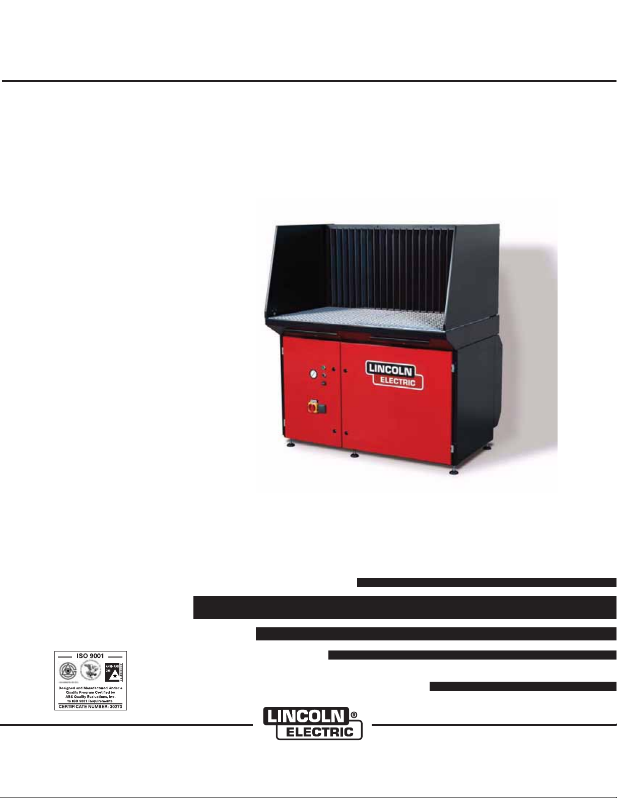
GENERAL DESCRIPTION
The downdraft table is a workbench with an integrated
extraction fan and filtration system that is used for
welding, grinding and plasma cutting applications.
Depending on the specific application, the use of certain accessories is required and/or recommended.
See Accessories section of this manual.
The downdraft table features a work grid, a three-stage
prefiltration system for optimum spark arresting and
two oval main filter cartridges. Both pre and main filters
have dust drawers underneath. The working height of
the downdraft table is adjustable. The control panel
contains a 120V power outlet for connection of any
device, such as a vacuum cleaner or grinding machine
(max. 1200W).
INTENDED USE
The product has been designed as a workbench with
integrated extraction and filtration facility for welding
and grinding purposes, provided the appropriate
options have been installed (See Accessories
Section of this manual). Using the product for other
purposes is considered contrary to its intended use.
The manufacturer accepts no liability for any damage
or injury resulting from such use. The product has been
built in accordance with state-of-the-art standards and
recognized safety regulations. Only use this product
when in technically perfect condition in accordance
with its intended use and the instructions explained in
the user manual.
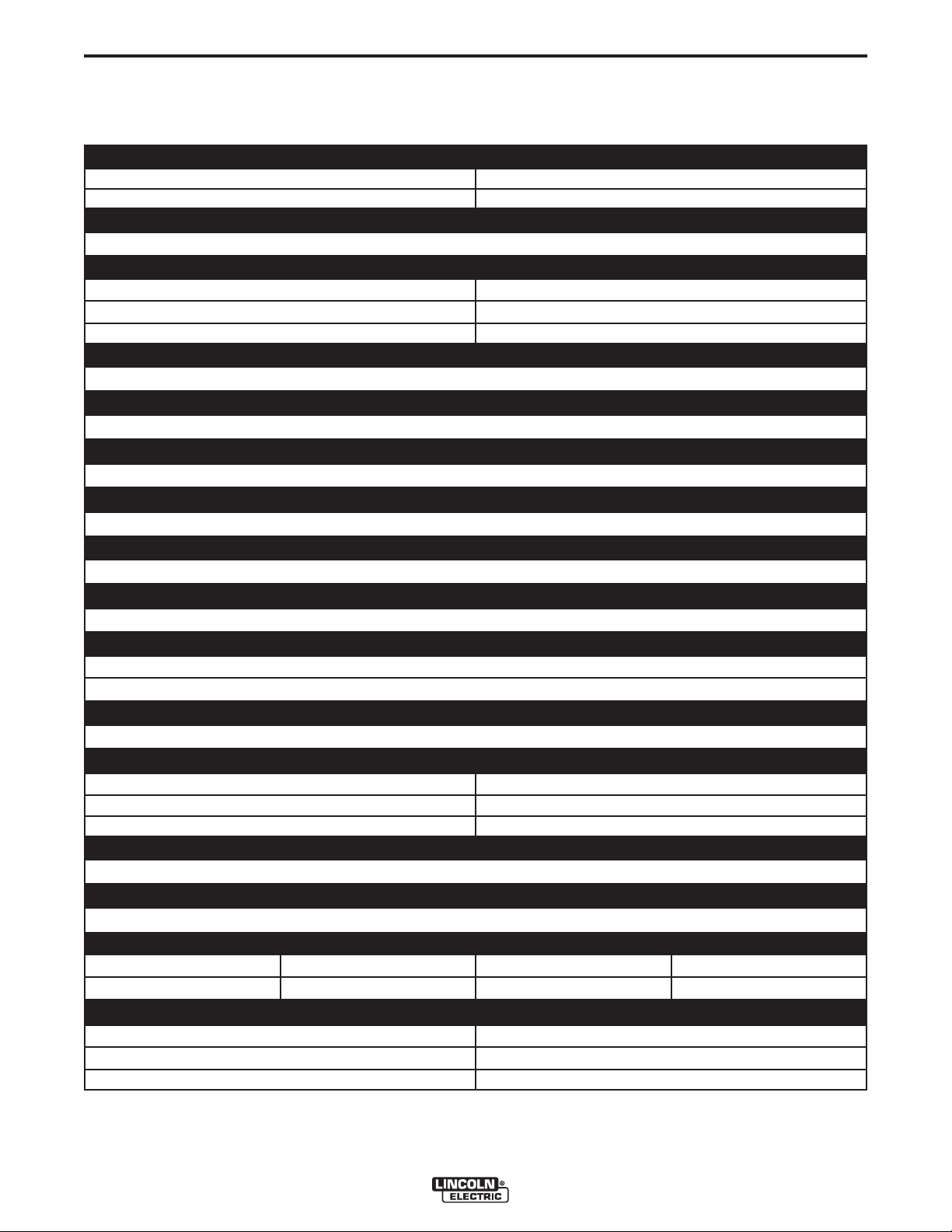
FIGURE A.1 – COMPONENTS
H
A
B
C
D
E
F
G
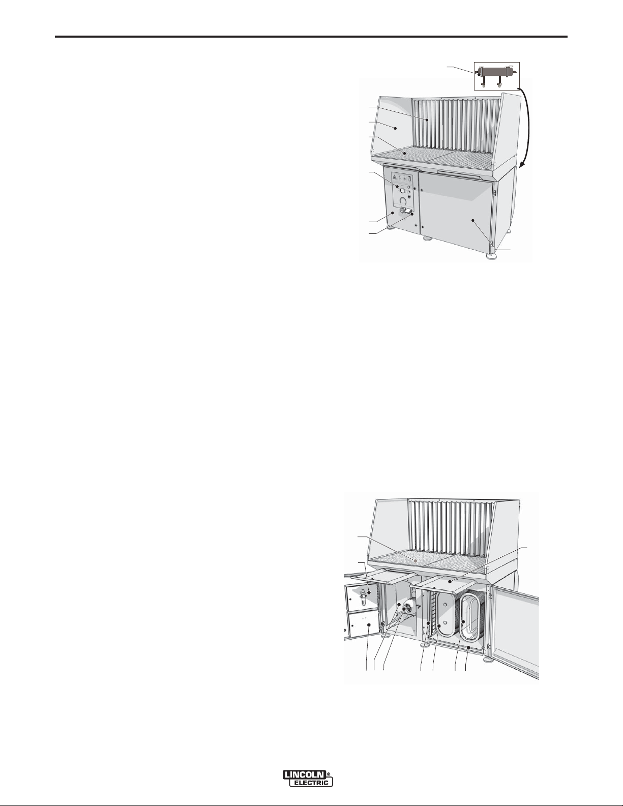
I. Prefilters (1st stage)
J. Dust drawers (prefiltration)
K. Dust drawer (main filter cartridges)
L. Filter cleaning mechanism (DownFlex 400-MS and
DownFlex 400-MS/A only)
M. Filter cartridges (2)
N. Prefilters (2nd stage)
O. Fan
P. Outlet grid
COMPONENTS
The downdraft table consists of the following main
components See Figures A.1 and A.2:
A. Backdraft kit
B. Side panels (left + right)
C. Work grid (two-piece)
D. Control panel
E. Left door (controls/fan)
F. Power outlet
G. Right door (filter compartment)
H. Compressed air tank (DownFlex 400-MS and
DownFlex 400-MS/A only)
Q. Electrics high voltage
R. Electrics low voltage
FIGURE A.2 – COMPONENTS
I
R
P
O
Q
N M
J
KL
DOWNFLEX 200/400
A-3
INSTALLATION
A-3
INSTALLATION
TOOLS AND REQUIREMENTS
The following tools and requirements are needed to
install the product:
• Spanner M6 and M8
• Hexagon wrench 10 and 13 ( in.)
UNPACKING
Check that the product is complete. The package
should contain:
• Downdraft table
• Work grid (two-piece)
• Cover strip with 8 bolts M6 (cover strip not included
when backdraft kit and side panels are standard
equipment; bolts packed with backdraft kit)
• Square key 8 mm (to lock/unlock doors)
• Square key 6 mm (to lock/unlock dust drawers and
doors of electrics)
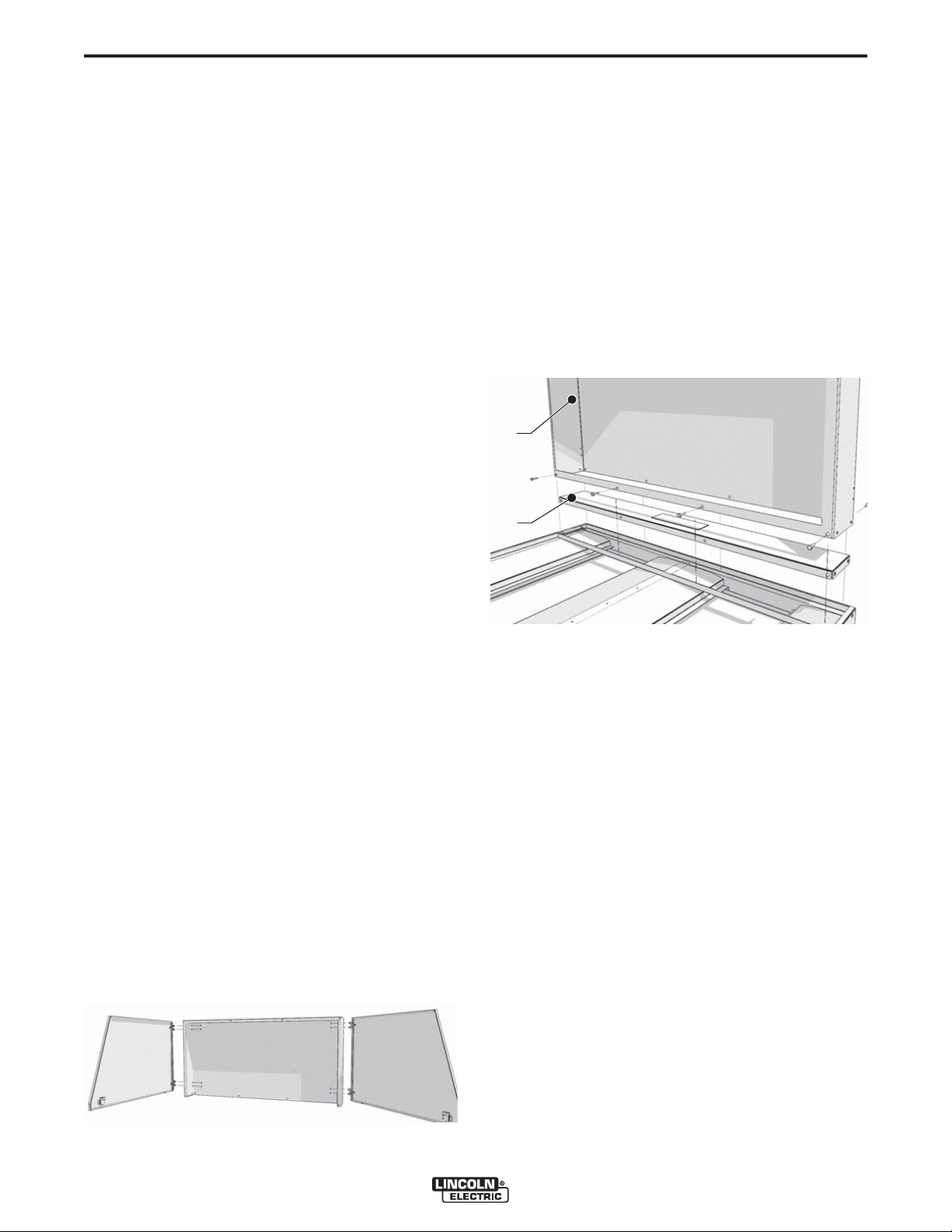
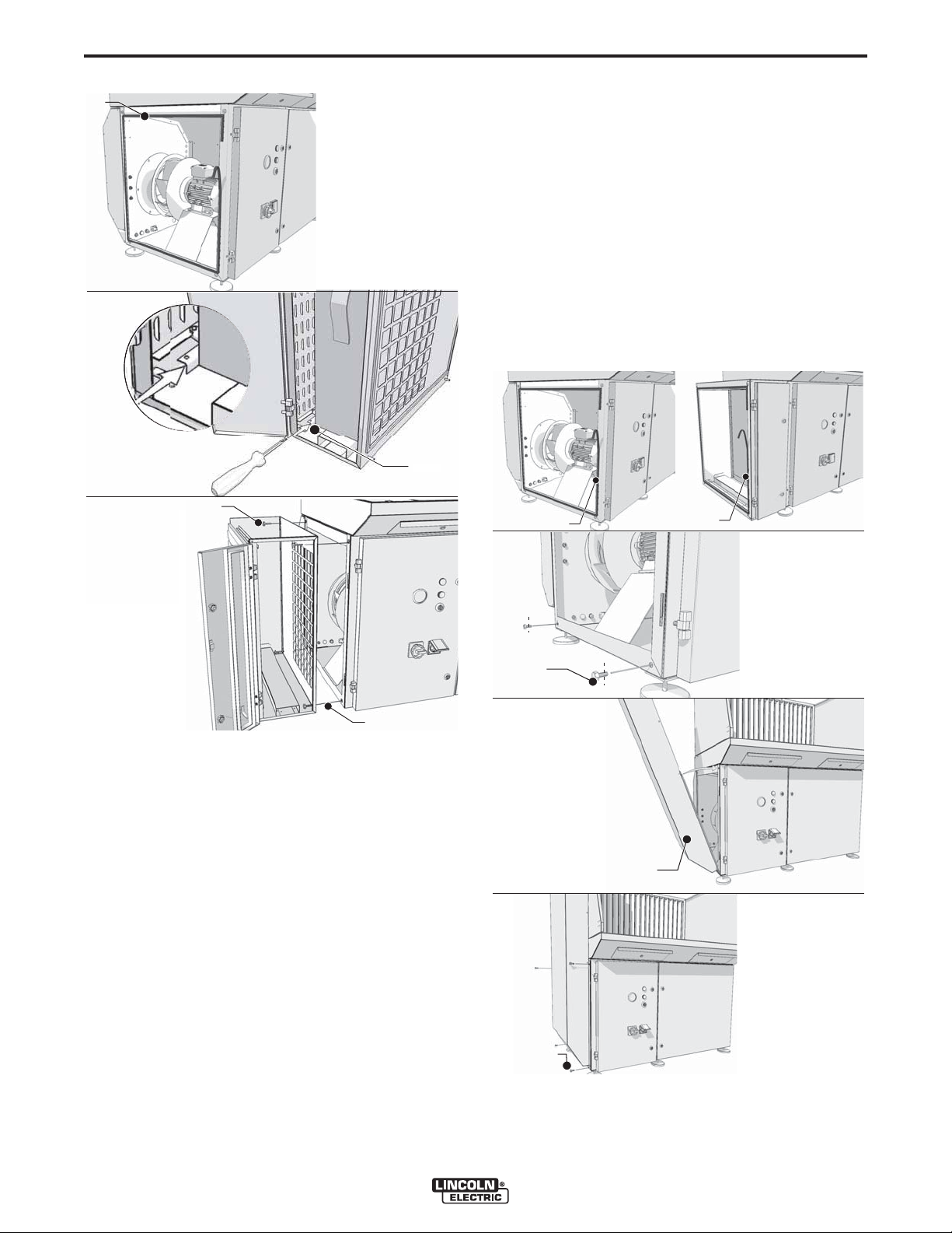
BACK PANEL
To mount the back panel, proceed as follows. See
Figure A.4.
1. Unscrew the cover strip.
2. Place the back panel (A). See Figure A.4.
3. Place the cover strip (B) inside the back panel. See
Figure A.4.
4. Fasten the back panel and cover strip using the 8
bolts.
FIGURE A.4 – BACK PANEL
A
B
If parts are missing or damaged, contact your supplier.
OPTIONS
Mount optional side panels, back panel, backdraft kit,
and/or plasma cutting work grid, if any. Otherwise,
refer to Work Grid for mounting of work grid.
SIDE PANELS
Side panels are to be mounted to the back panel or
backdraft kit. See Figure A.3.
To mount the side panels, proceed as follows.
1. Unscrew the bolts on the loose side of the hinges
and remove the washers; keep the bolts and washers.
2. Put the pins through the holes on the sides of the
back panel or backdraft panel.
3. Place the washers and bolts over the pins.
4. Tighten the bolts.
FIGURE A.3 – SIDE PANELS
BACKDRAFT KIT
The backdraft kit consists of:
• Backdraft panel
• 2 Narrowing plates
NOTE: When the downdraft table will be used for
grinding only, it is not necessary to mount the
narrowing plates. For welding and plasma cutting, however, the narrowing plates are
required.
To mount the backdraft kit, proceed as follows.
1. Unscrew the cover strip. (Keep the 8 bolts)
NOTE: Downdraft table contains no cover strip when
backdraft kit and side panels are standard
equipment; bolts packed with backdraft kit.
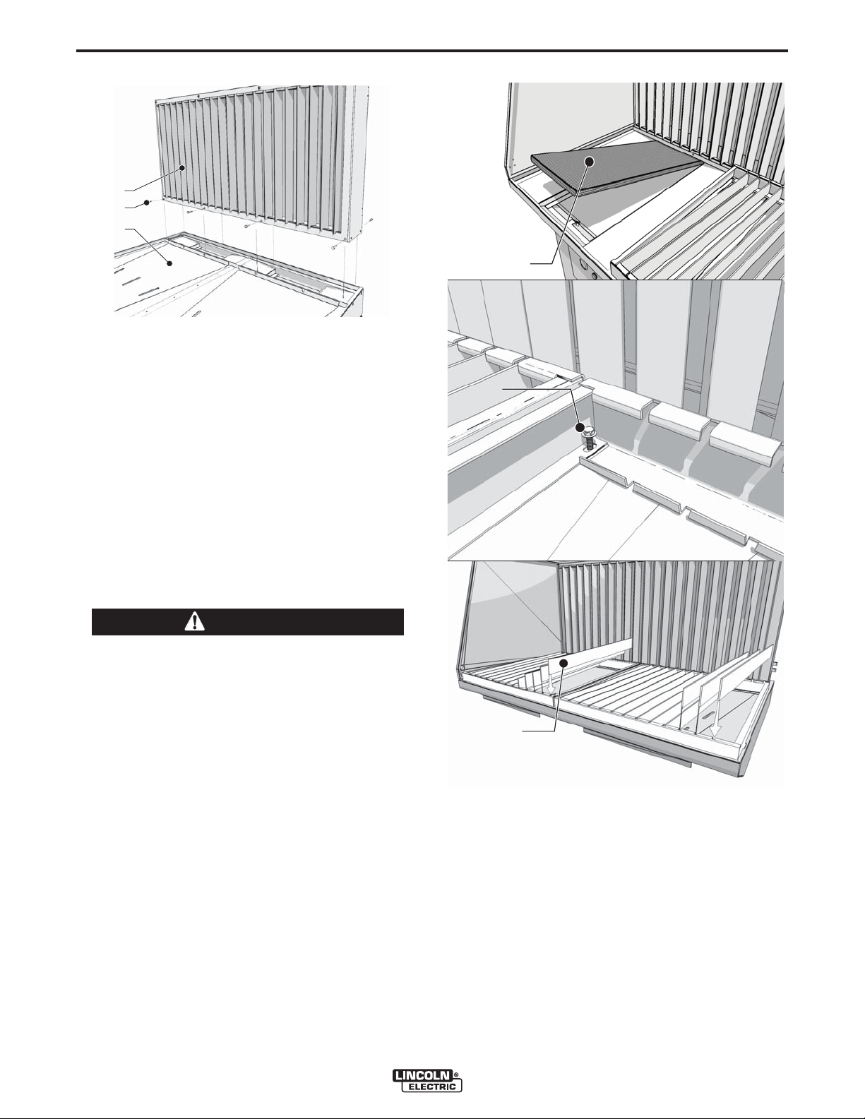
2. Place the narrowing plates (C). See Figure A.5.
3. Place the backdraft panel (A). See Figure A.5.
4. Fasten the narrowing plates and the backdraft
panel using the 8 bolts (B). See Figure A.5.
The supplied cover strip is not used.
DOWNFLEX 200/400
A-4
FIGURE A.5 – BACKDRAFT KIT
A
B
C
INSTALLATION
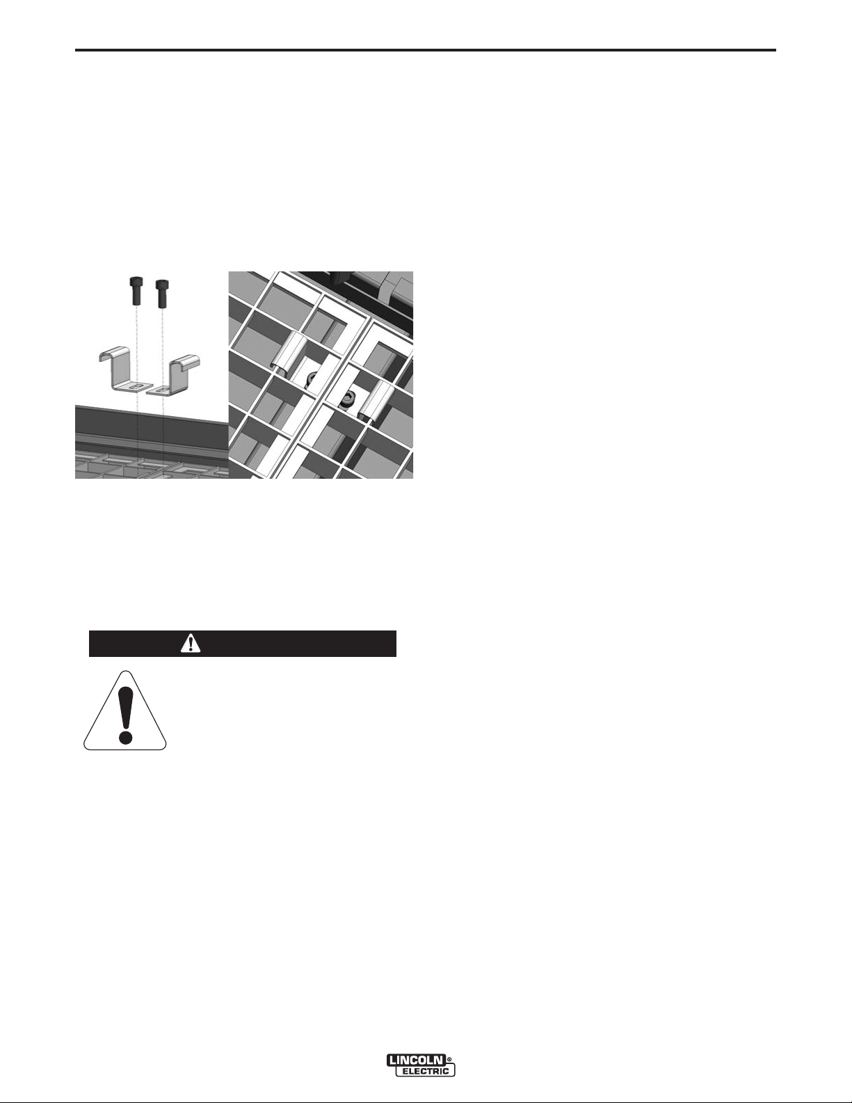
PLASMA CUTTING WORK GRID
The plasma cutting work grid consists of:
• 2 Grid frames 28.9 x 26.3 x 2.5 in. (735 x 669 x 64
mm)
• 2 x 13 Metal bars 28.54 x 2.36 x 0.16 in. (725 x 60 x
4 mm)
A-4
FIGURE A.6 – PLASMA CUTTING WORK GRID
A
B
• 2 Additional perforated steel spark arresters
To mount the plasma cutting work grid, proceed as follows.
1. Place the perforated steel spark arresters over the
prefilters (A). The edgeless sides should be directed to the back. See Figure A.6.
CAUTION
Do not remove the standard prefilters.
------------------------------------------------------------------------
2. Remove the ground bracket at the position of the
work grid. Keep the two bolts.
3. Place the frames into position.
4. Fasten the frames using the 2 bolts (B). See Figure
A.6.
NOTE: It is necessary to install the bolts to ground the
work grids.
5. Place the bars (C). See Figure A.6.
NOTE: The supplied standard work grid and the
ground bracket are not used.
C (x26)
DOWNFLEX 200/400
A-5
INSTALLATION
WORK GRID
To mount the standard work grid, proceed as follows.
See Figure A.7.
1. Loosen the ground bracket.
2. Place the work grids into position.
3. Place the ground bracket over both work grids.
4. Tighten the ground bracket.
FIGURE A.7 – WORK GRID
A-5
3. Unlock the HEPA filter cartridge by pressing a
screwdriver or other tool at the position of the strips
(B) on the top and bottom of unit. See Figure A.8.
4. Take out the filter cartridge.
5. Mount the adjustable feet underneath the HEPA kit.
NOTE: Remove the outlet panel from the HEPA kit, as
well as the outlet grid inside the downdraft
table, to facilitate mounting. Donʼt forget to
replace them when mounting is complete.
6. Place bolts halfway through the 2 upper holes (C) at
the outlet of the downdraft table. See Figure A.8.
7. Hang the HEPA box on the bolts.
8. Place bolts through the 2 lower holes (D) in the
HEPA box. See Figure A.8.
9. Fasten the HEPA box by tightening the 4 bolts
(C+D). See Figure A.8.
10. Replace the filter cartridge.
11. Lock the filter cartridge by pulling the two straps
tightly. This is indicated by a “click” sound.
NOTE: It is necessary to install the bracket to ground
the work grids.
INSTALLATION OF REMAINING OPTIONS
HEPA KIT
ATTENTION
Handle HEPA box and filter cartridge with care during unpacking
and mounting to avoid damage.
------------------------------------------------------------------------
The HEPA kit consists of:
• HEPA box with filter
• 2 Adjustable feet
• 4 Spare bolts M6
NOTE: If a Silencer/Outlet duct has to be installed as
well, the outlet panel of the HEPA kit does not
need to be mounted.
12. Adjust the feet when the downdraft table is placed
in place in its final position.
NOTE: The outlet panel of the downdraft table is not
used.
• Draft strip
To mount the HEPA kit, proceed as follows.
1. Unscrew and remove the outlet panel from the
downdraft table. Keep he 4 screws See Figure
A.8, top image.
2. Apply the draft strip to the downdraft table (A). See
Figure A.8.
DOWNFLEX 200/400
A-6
A
FIGURE A.8 – HEPA KIT
INSTALLATION
3. Place bolts halfway through the 2 lower holes at the
outlet of the downdraft table or HEPA box (C). See
Figure A.9.
4. Place the silencer/outlet duct over the bolts (D).
See Figure A.9.
5. Put the silencer/outlet duct in an upright position
and place 2 bolts in the 2 upper holes.
6. Fasten the silencer/outlet duct by tightening the 4
bolts (E). See Figure A.9.
NOTE: The outlet panel of the downdraft table is not
used.
FIGURE A.9 – SILENCER / OUTLET DUCT
B (2x)
A-6
C (x2)
D (x2)
SILENCER/OUTLET DUCT
The Silencer/Outlet duct consists of:
• Shaft
• Draft strip
The Silencer/outlet duct can be connected to the
HEPA kit or directly to the downdraft table.
To mount the silencer/outlet duct, proceed as follows.
See Figure A.9.
C (x2)
A
B
D
1. If necessary: unscrew the outlet panel of the downdraft table or the outlet panel of the HEPA kit. Keep
the 4 bolts.
2. Apply the draft strip to the downdraft table (A) or
HEPA kit (B). See Figure A.9.
DOWNFLEX 200/400
E (x4)
A-7
INSTALLATION
A-7
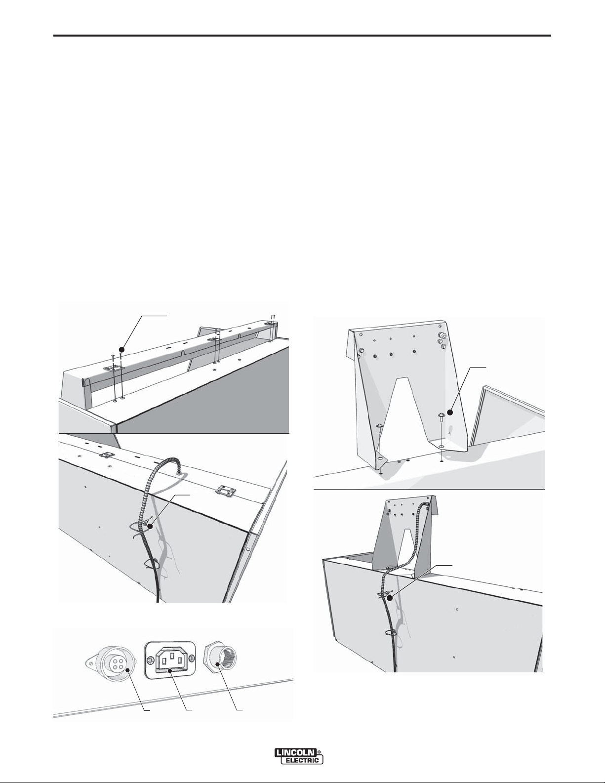
WORKING LIGHT
The working light consists of:
• Lighting fixture with 7.5 ft (2.3 m) of cable and plug
• 6 Bolts M6
• 3 Tie-wraps
To mount the working light, proceed as follows.
1. Mount the lighting fixture using the 6 bolts (A). See
Figure A.10.
2. Route the cable down the back side of the downdraft table.
3. Attach the cable to the back panel or backdraft
panel using the 3 tie-wraps (B). See Figure A.10.
4. Connect the cable. See Figure A.11, item B.
FIGURE A.10 – WORKING LIGHT
A (x6)
MOVEMENT SENSOR
(DownFlex 400-MS/A only)
The movement sensor consists of:
• Automatic start/stop device with 7.5 ft (2.3 m) of cable
and plug
• 2 Bolts M6
• 3 Tie-wraps
To mount the movement sensor, proceed as follows.
1. Mount the movement sensor on top of the back
panel or backdraft panel using the 2 bolts (A). See
Figure A.12.
2. Lead the cable down the back side of the downdraft
table.
3. Attach the cable to the back panel or backdraft
panel using the 3 tie-wraps (B). See Figure A.12.
4. Connect the cable. See Figure A.11, item A.
FIGURE A.12 – MOVEMENT SENSOR
B (x3)
FIGURE A.11 – CONNECTIONS
ar-
e
r
-
-
r
rea
-
A (x2)
B (x3)
CA B
DOWNFLEX 200/400
A-8
INSTALLATION
A-8
WELDING CABLE SENSOR
(DownFlex 400-MS/A only)
The welding cable sensor consists of:
• Clamp with 7.5 ft (2.3 m) of cable and plug
To mount the welding cable sensor, proceed as follows.
1. Connect the cable. See Figure A.11, item A.
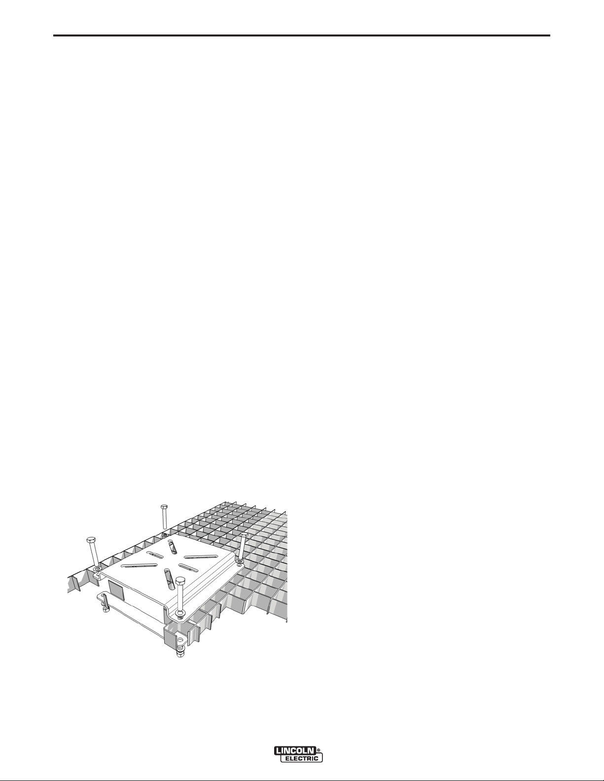
BENCH VICE MOUNTING BRACKET
The bench vice mounting bracket can be mounted
on the standard work grid only.
The bench vice mounting bracket consists of:
• Mounting bracket
• 2 Strips
• 4 Bolts M6
• 4 Nuts M6
• 8 Washers
To mount the bench vice mounting bracket, proceed as
follows.
1. Position the mounting bracket on the grid.
2. Place the strips underneath the grid and fasten
them using the bolts, nuts and washers. See
Figure A.13.
3. Place the strips underneath the grid and fasten
them using (from bottom to top): nut - washer - strip
- grid - mounting bracket - washer - bolt.
FIGURE A.13 – BENCH VICE MOUNTING
BRACKET
WHEEL KIT
The wheel kit consists of:
• 2 Swivel casters with brakes
• 3 Swivel casters without brakes
To mount the wheel kit, proceed as follows.
1. Carefully lift the downdraft table using a fork-lift
truck or pallet jack.
2. Unscrew the 5 adjustable feet.
3. Mount the swivel casters; mount the ones with
brakes at the left and right front corners.
NOTE: Drive in the screw thread of the swivel casters
as deep as possible.
NOTE: By the use of the wheel set, the working height
of the downdraft table is fixed to 37.4 in. (950
mm).
COMPRESSED AIR CONNECTION
(DownFlex 400-MS and DownFlex 400-MS/A only)
The downdraft table functions on compressed air with
a recommended working pressure of 72-115 psi (5-8
bar). Always make sure that the working pressure is
between these values (preferably at 72 psi/5 bar). If
required, mount a pressure reducing valve to prevent
overpressure. If the pressure is too high, the safety
valve of the system will be opened, thus decreasing
the pressure until the system pressure has reached an
appropriate level.
1. Connect the downdraft table to compressed air.
See Figure A.11, item C. Connection ⅜ in.
POSITIONING
The downdraft table can be positioned using:
• A fork-lift truck (preferred way); or
• A pallet jack (downdraft table has to be tilted); or
• Cargo lashings lifted by a fork-lift truck. See Figure
A.14.
DOWNFLEX 200/400
 Loading...