

Page 1

SVM142-A
September, 2002
Safety Depends on You
Lincoln arc welding and cutting
equipment is designed and built
with safety in mind. However,
your overall safety can be
increased by proper installation
. . . and thoughtful operation on
your part. DO NOT INSTALL,
OPERATE OR REPAIR THIS
EQUIPMENT WITHOUT READING THIS MANUAL AND THE
SAFETY PRECAUTIONS CONTAINED THROUGHOUT. And,
most importantly, think before
you act and be careful.
SERVICE MANUAL
For use with machine code number 10501 thru 10510
IDEALARC ™DC-655
Return to Master TOC Return to Master TOC Return to Master TOC Return to Master TOC
View Safety Info View Safety Info View Safety Info View Safety Info
RETURN TO MAIN INDEX
• Sales and Service through Subsidiaries and Distributors Worldwide •
Cleveland, Ohio 44117-1199 U.S.A. TEL: 216.481.8100 FAX: 216.486.1751 WEB SITE: www.lincolnelectric.com
• World's Leader in Welding and Cutting Products •
Copyright © 2002 Lincoln Global Inc.
Page 2
Return to Master TOC Return to Master TOC Return to Master TOC Return to Master TOC
SAFETY
i i
IDEALARC DC-655
FOR ENGINE
powered equipment.
1.a. Turn the engine off before troubleshooting and maintenance
work unless the maintenance work requires it to be running.
____________________________________________________
1.b.Operate engines in open, well-ventilated
areas or vent the engine exhaust fumes
outdoors.
____________________________________________________
1.c. Do not add the fuel near an open flame weld-
ing arc or when the engine is running. Stop
the engine and allow it to cool before refueling to prevent spilled fuel from vaporizing on
contact with hot engine parts and igniting. Do
not spill fuel when filling tank. If fuel is spilled,
wipe it up and do not start engine until fumes
have been eliminated.
____________________________________________________
1.d. Keep all equipment safety guards , cov ers and
devices in position and in good repair.Keep
hands, hair, clothing and tools away from Vbelts, gears, fans and all other moving parts
when starting, operating or repairing equipment.
____________________________________________________
1.e. In some cases it may be necessary to remove safety
guards to perform required maintenance. Remove
guards only when necessary and replace them when the
maintenance requiring their removal is complete.
Always use the greatest care when working near moving
parts.
___________________________________________________
1.f. Do not put your hands near the engine fan. Do not attempt to
override the governor or idler by pushing on the throttle control rods while the engine is running.
___________________________________________________
1.g. To prevent accidentally starting gasoline engines while
turning the engine or welding generator during maintenance
work, disconnect the spark plug wires, distributor cap or
magneto wire as appropriate.
ARC WELDING CAN BE HAZARDOUS. PROTECT YOURSELF AND OTHERS FROM POSSIBLE SERIOUS INJURY OR DEATH.
KEEP CHILDREN AWAY. PACEMAKER WEARERS SHOULD CONSULT WITH THEIR DOCTOR BEFORE OPERATING.
Read and understand the following saf ety highlights.For additional safety inf ormation, it is strongly recommended that you purchase a copy of “Safety in Welding & Cutting - ANSI Standard Z49.1” from the American Welding Society, P.O. Box 351040,
Miami, Florida 33135 or CSA Standard W117.2-1974. A Free copy of “Arc Welding Safety” booklet E205 is available from the
Lincoln Electric Company, 22801 St. Clair Avenue, Cleveland, Ohio 44117-1199.
BE SURE THAT ALL INSTALLATION, OPERATION, MAINTENANCE AND REPAIR PROCEDURES ARE
PERFORMED ONLY BY QUALIFIED INDIVIDUALS.
WARNING
ELECTRIC AND
MAGNETIC FIELDS
may be dangerous
2.a. Electric current flowing through any conductor causes
localized Electric and Magnetic Fields (EMF). Welding
current creates EMF fields around welding cables and
welding machines
2.b. EMF fields may interfere with some pacemakers, and
welders having a pacemaker should consult their physician
before welding.
2.c. Exposure to EMF fields in welding may have other health
effects which are now not known.
2.d. All welders should use the following procedures in order to
minimize exposure to EMF fields from the welding circuit:
2.d.1.
Route the electrode and work cables together - Secure
them with tape when possible.
2.d.2. Never coil the electrode lead around your body.
2.d.3. Do not place your body between the electrode and
work cables. If the electrode cable is on your right
side, the work cable should also be on your right side.
2.d.4. Connect the work cable to the workpiece as close as
possible to the area being welded.
2.d.5. Do not work next to welding power source.
1.h. To avoid scalding, do not remove the
radiator pressure cap when the engine is
hot.
CALIFORNIA PROPOSITION 65 WARNINGS
Diesel engine exhaust and some of its constituents
are known to the State of California to cause cancer, birth defects, and other reproductive harm.
The engine exhaust from this product contains
chemicals known to the State of California to cause
cancer, birth defects, or other reproductive harm.
The Above For Diesel Engines
The Above For Gasoline Engines
Page 3
Return to Master TOC Return to Master TOC Return to Master TOC Return to Master TOC
SAFETY
ii ii
IDEALARC DC-655
ARC RAYS can burn.
4.a. Use a shield with the proper filter and cover
plates to protect your eyes from sparks and
the rays of the arc when welding or observing
open arc welding. Headshield and filter lens
should conform to ANSI Z87. I standards.
4.b. Use suitable clothing made from durable flame-resistant
material to protect your skin and that of your helpers from
the arc rays.
4.c. Protect other nearby personnel with suitable, non-flammable
screening and/or warn them not to watch the arc nor expose
themselves to the arc rays or to hot spatter or metal.
ELECTRIC SHOCK can kill.
3.a. The electrode and work (or ground) circuits
are electrically “hot” when the welder is on.
Do not touch these “hot” parts with your bare
skin or wet clothing. Wear dry, hole-free
gloves to insulate hands.
3.b. Insulate yourself from work and ground using dry insulation.
Make certain the insulation is large enough to cover your full
area of physical contact with work and ground.
In addition to the normal safety precautions, if welding
must be performed under electrically hazardous
conditions (in damp locations or while wearing wet
clothing; on metal structures such as floors, gratings or
scaffolds; when in cramped positions such as sitting,
kneeling or lying, if there is a high risk of unavoidable or
accidental contact with the workpiece or ground) use
the following equipment:
• Semiautomatic DC Constant Voltage (Wire) Welder.
• DC Manual (Stick) Welder.
• AC Welder with Reduced Voltage Control.
3.c. In semiautomatic or automatic wire welding, the electrode,
electrode reel, welding head, nozzle or semiautomatic
welding gun are also electrically “hot”.
3.d. Always be sure the work cable makes a good electrical
connection with the metal being welded. The connection
should be as close as possible to the area being welded.
3.e. Ground the work or metal to be welded to a good electrical
(earth) ground.
3.f.
Maintain the electrode holder, work clamp, welding cable and
welding machine in good, safe operating condition.Replace
damaged insulation.
3.g. Never dip the electrode in water for cooling.
3.h. Never simultaneously touch electrically “hot” parts of
electrode holders connected to two welders because voltage
between the two can be the total of the open circuit voltage
of both welders.
3.i. When working above floor level, use a safety belt to protect
yourself from a fall should you get a shock.
3.j. Also see Items 6.c.and 8.
FUMES AND GASES
can be dangerous.
5.a.Welding may produce fumes and gases
hazardous to health. Avoid breathing these
fumes and gases.When welding, keep
your head out of the fume. Use enough
ventilation and/or exhaust at the arc to keep
fumes and gases away from the breathing zone. When
welding with electrodes which require special
ventilation such as stainless or hard facing (see
instructions on container or MSDS) or on lead or
cadmium plated steel and other metals or coatings
which produce highly toxic fumes, keep exposure as
low as possible and below Threshold Limit Values (TLV)
using local exhaust or mechanical ventilation. In
confined spaces or in some circumstances, outdoors, a
respirator may be required. Additional precautions are
also required when welding on galvanized steel.
5.b.
Do not weld in locations near chlorinated hydrocarbon
vapors
coming from degreasing, cleaning or spraying operations.
The heat and rays of the arc can react with solvent vapors
to
form phosgene, a highly toxic gas, and other irritating
products.
5.c. Shielding gases used for arc welding can displace air and
cause injury or death. Always use enough ventilation,
especially in confined areas, to insure breathing air is safe.
5.d. Read and understand the manufacturer’s instructions for this
equipment and the consumables to be used, including the
material safety data sheet (MSDS) and follow your
employer’s safety practices. MSDS forms are available from
your welding distributor or from the manufacturer.
5.e. Also see item 1.b.
Page 4
Return to Master TOC Return to Master TOC Return to Master TOC Return to Master TOC
SAFETY
iii iii
IDEALARC DC-655
FOR ELECTRICALLY
powered equipment.
8.a.Turn off input power using the disconnect
switch at the fuse box before working on
the equipment.
8.b. Install equipment in accordance with the U.S. National
Electrical Code, all local codes and the manufacturer’s
recommendations.
8.c. Ground the equipment in accordance with the U.S. National
Electrical Code and the manufacturer’s recommendations.
CYLINDER may explode
if damaged.
7.a. Use only compressed gas cylinders
containing the correct shielding gas for the
process used and properly operating
regulators designed for the gas and
pressure used. All hoses, fittings, etc. should be suitable for
the application and maintained in good condition.
7.b. Always keep cylinders in an upright position securely
chained to an undercarriage or fixed support.
7.c. Cylinders should be located:
•Away from areas where they may be struck or subjected to
physical damage.
•A safe distance from arc welding or cutting operations and
any other source of heat, sparks, or flame.
7.d. Never allow the electrode, electrode holder or any other
electrically “hot” parts to touch a cylinder.
7.e. Keep your head and face away from the cylinder valve outlet
when opening the cylinder valve.
7.f. Valve protection caps should always be in place and hand
tight except when the cylinder is in use or connected for
use.
7.g. Read and follow the instructions on compressed gas
cylinders, associated equipment, and CGA publication P-l,
“Precautions for Safe Handling of Compressed Gases in
Cylinders,” available from the Compressed Gas Association
1235 Jefferson Davis Highway, Arlington, VA 22202.
WELDING SPARKS can
cause fire or explosion.
6.a.
Remove fire hazards from the welding area.
If this is not possible, cover them to prevent
the welding sparks from starting a fire.
Remember that welding sparks and hot
materials from welding can easily go through small cracks
and openings to adjacent areas. Avoid welding near
hydraulic lines. Have a fire extinguisher readily available.
6.b. Where compressed gases are to be used at the job site,
special precautions should be used to prevent hazardous
situations. Refer to “Safety in Welding and Cutting” (ANSI
Standard Z49.1) and the operating information for the
equipment being used.
6.c. When not welding, make certain no part of the electrode
circuit is touching the work or ground. Accidental contact can
cause overheating and create a fire hazard.
6.d. Do not heat, cut or weld tanks, drums or containers until the
proper steps have been taken to insure that such procedures
will not cause flammable or toxic vapors from substances
inside. They can cause an explosion even
though
they have
been “cleaned”. For information, purchase “Recommended
Safe Practices for the
Preparation
for Welding and Cutting of
Containers and Piping That Have Held Hazardous
Substances”, AWS F4.1 from the American Welding Society
(see address above).
6.e. Vent hollow castings or containers before heating, cutting or
welding.They may explode.
6.f.
Sparks and spatter are thrown from the welding arc. Wear oil
free protective garments such as leather gloves, heavy shirt,
cuffless trousers, high shoes and a cap over your hair. Wear
ear plugs when welding out of position or in confined places.
Always wear safety glasses with side shields when in a
welding area.
6.g. Connect the work cable to the work as close to the welding
area as practical. Work cables connected to the building
framework or other locations away from the welding area
increase the possibility of the welding current passing
through lifting chains, crane cables or other alternate circuits.
This can create fire hazards or overheat lifting chains or
cables until they fail.
6.h. Also see item 1.c.
Page 5

Return to Master TOC Return to Master TOC Return to Master TOC Return to Master TOC
SAFETY
iv iv
IDEALARC DC-655
PRÉCAUTIONS DE SÛRETÉ
Pour votre propre protection lire et observer toutes les instructions
et les précautions de sûreté specifiques qui parraissent dans ce
manuel aussi bien que les précautions de sûreté générales suivantes:
Sûreté Pour Soudage A L’Arc
1. Protegez-vous contre la secousse électrique:
a. Les circuits à l’électrode et à la piéce sont sous tension
quand la machine à souder est en marche. Eviter toujours tout contact entre les parties sous tension et la
peau nue ou les vétements mouillés. Porter des gants
secs et sans trous pour isoler les mains.
b. Faire trés attention de bien s’isoler de la masse quand
on soude dans des endroits humides, ou sur un plancher metallique ou des grilles metalliques, principalement
dans les positions assis ou couché pour lesquelles une
grande partie du corps peut être en contact avec la
masse.
c. Maintenir le porte-électrode, la pince de masse, le câble
de soudage et la machine à souder en bon et sûr état
defonctionnement.
d. Ne jamais plonger le porte-électrode dans l’eau pour le
refroidir.
e. Ne jamais toucher simultanément les parties sous ten-
sion des porte-électrodes connectés à deux machines à
souder parce que la tension entre les deux pinces peut
être le total de la tension à vide des deux machines.
2. Dans le cas de travail au dessus du niveau du sol, se protéger
contre les chutes dans le cas ou on recoit un choc. Ne jamais
enroule le câble-électrode autour de n’importe quelle partie
du corps.
3. Un coup d’arc peut être plus sévère qu’un coup de soliel,
donc:
a. Utiliser un bon masque avec un verre filtrant approprié
ainsi qu’un verre blanc afin de se protéger les yeux du
rayonnement de l’arc et des projections quand on soude
ou quand on regarde l’arc.
b. Porter des vêtements convenables afin de protéger la
peau de soudeur et des aides contre le rayonnementde
l’arc.
c. Protéger l’autre personnel travaillant à proximité au
soudage à l’aide d’écrans appropriés et non-inflammables.
4. Des gouttes de laiter en fusion sont émises de l’arc de
soudage. Se protéger avec es vêtements de protection libres
de l’huile, tels que les gants en cuir, chemise épaisse, pantalons sans revers, et chaussures montantes.
5. Toujours porter des lunettes de sécurité dans la zone de
soudage. Utiliser des lunettes avec écrans lateraux dans les
zones où l’on pique le laitier.
6. Eloigner les matériaux inflammables ou les recouvrir afin de
prévenir ttout risque d’incendie dû étincelles.
7. Quand on ne soude pas, poser la pince à une endroit isolé
de la masse. Un court-circuit accidental peut provoquer un
échauffement et un risque d’incendie.
8. S’assurer que la masse est connectée le plus prés possible
de la zone de travail qu’il est pratique de la faire. Si on place
la masse sur la charpente de la construction ou d’autres
endroits éloignés de la zone de travail, on augmente le
risque de voir passer le courant de soudage par les chaines
de levage, câbles de grue, ou atres circuits. Cela peut
provoquer des risques d’incendie ou d’echauffement des
chaines et des câbles jusqu’à ce qu’ils se rompent.
9. Assurer une ventilation suffisante dans la zone de soudage.
Ceci est particuliérement important pour le soudage de tôles
galvanisées plombées, ou cadmiées ou tout autre métal qui
produit des fumées toxiques.
10. Ne pas souder en présence de vapeurs de chlore provenant
d’opéerations de dégraissage, nettoyage ou pistolage. La
chaleur ou les rayons de l’arc peuvent réagir avec les
vapeurs du solvant pour produire du phosgéne (gas fortement roxique) ou autres produits irritants.
PRÉCAUTIONS DE SÛRETÉ POUR LES
MACHINES À SOUDER À TRANSFORMATEUR ET À REDRESSEUR
1. Relier à la terre le chassis du poste conformement au code
de l’électricité et aux recommendations du fabricant. Le dispositif de montage ou la piece à souder doit être branché à
une bonne mise à la terre.
2. Autant que possible, l’installation et l’entretien du poste
seront effectués par un électricien qualifié.
3. Avant de faires des travaux à l’interieur de poste, la
debrancher à l’interrupteur à la boite de fusibles.
4. Garder tous les couvercles et dispostifis de sûreté à leur
place.
Page 6

MASTER TABLE OF CONTENTS FOR ALL SECTIONS
v v
IDEALARC DC-655
Page
Safety.................................................................................................................................................i-iv
Installation.............................................................................................................................Section A
Technical Specifications .............................................................................................................A-2
Safety Precautions......................................................................................................................A-4
Select Suitable Location (Stacking, Tilting, Lifting) ....................................................................A-4
Electrical Input Connections.......................................................................................................A-4
Reconnect Procedure .................................................................................................................A-5
Output Connections....................................................................................................................A-6
Operation...............................................................................................................................Section B
Safety Precautions......................................................................................................................B-2
General Description ....................................................................................................................B-3
Controls and Settings.................................................................................................................B-4
Case Back Connections.............................................................................................................B-6
Auxiliary Power ...........................................................................................................................B-6
Machine Protection.....................................................................................................................B-6
Welding Performance .................................................................................................................B-8
Accessories...........................................................................................................................Section C
Maintenance .........................................................................................................................Section D
Safety Precautions......................................................................................................................D-2
General Maintenance..................................................................................................................D-2
General Component Locations...................................................................................................D-3
Theory of Operation .............................................................................................................Section E
Troubleshooting and Repair.................................................................................................Section F
How to Use Troubleshooting Guide............................................................................................F-2
PC Board Troubleshooting Procedures ......................................................................................F-3
Troubleshooting Guide ................................................................................................................F-4
Test Procedures ........................................................................................................................F-13
Oscilloscope Waveforms ..........................................................................................................F-43
Replacement Procedures..........................................................................................................F-49
Retest After Repair....................................................................................................................F-57
Electrical Diagrams............................................................................................................. Section G
Parts Manual............................................................................................................................... P-317
RETURN TO MAIN INDEX
Page 7

Return to Master TOC Return to Master TOC Return to Master TOC Return to Master TOC
TABLE OF CONTENTS
- INSTALLATION SECTION -
Section A-1 Section A-1
IDEALARC DC-655
Installation .............................................................................................................................Section E
Technical Specifications - Idealarc DC-655 ...............................................................................A-2
Graphic Symbols that Appear on Rating Plate ..........................................................................A-3
Safety Precautions......................................................................................................................A-4
Select Suitable Location.............................................................................................................A-4
Stacking................................................................................................................................A-4
Tilting ....................................................................................................................................A-4
Electrical Input Connections.......................................................................................................A-4
Fuse and Wire Sizes.............................................................................................................A-4
Ground Connection..............................................................................................................A-4
Input Power Supply Connections ........................................................................................A-5
Reconnect Procedure.................................................................................................................A-5
Output Connections ...................................................................................................................A-6
Electrode and Work Cables..................................................................................................A-6
Auxiliary Power and Control Connections ...........................................................................A-7
Auxiliary Power Table.....................................................................................................A-7
115VAC Duplex Receptacle...........................................................................................A-7
230V Receptacle............................................................................................................A-7
14 Pin MS Type Receptacle...........................................................................................A-7
Terminal Strips ...............................................................................................................A-8
Page 8
Return to Section TOC Return to Section TOC Return to Section TOC Return to Section TOC
Return to Master TOC Return to Master TOC Return to Master TOC Return to Master TOC
A-2 A-2
IDEALARC DC-655
INSTALLATION
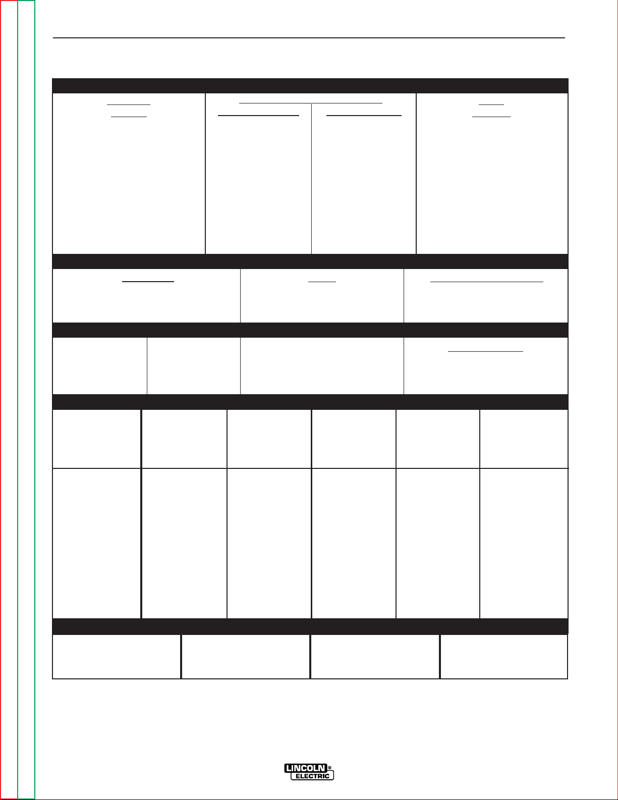
TECHNICAL SPECIFICATIONS – DC-655
Volts at Rated Amperes
44
44
Amps
650
815
Auxiliary Power
See the OPERATION section for
Auxiliary Power
information by model
Maximum Open Circuit Voltage
46 CV Mode
68 CC Mode
Duty Cycle
100% Duty Cycle
NEMA Class I (100)*
60% Duty Cycle
INPUT - THREE PHASE ONLY
OUTPUT
* European models meet IEC974-1 standards.
1
Also called “inverse time” or “thermal/magnetic” circuit breakers; circuit breakers which have a delay in tripping action that decreases as the magnitude of the current increases.
RECOMMENDED INPUT WIRE AND FUSE SIZES
Standard
Voltage
230/460/60
230/460/575/60
208/416/60
460/60
575/60
230/400/50/60*
380/500/50/60*
440/50/60
200/400/50/60
415/50/60
Code
Number
10501
10502
10503
10504
10505
10506
10507
10508
10509
10510
100% Duty Cycle
122/61
122/61/49
135/67.5
61
49
122/70
74/56
64
140/70
68
60% Duty Cycle
150/75
150/75/60
166/83
75
60
150/86
90/69
78
172/86
83
Input Current at Rated Output
RATED OUTPUT
INPUT
VOLTAGE /
FREQUENCY
208
230
416
460
575
200
230
380
400
415
440
500
(SUPER LAG)
OR BREAKER
SIZE (AMPS)
1
250 Amp
225 Amp
125 Amp
110 Amp
90 Amp
250 Amp
225 Amp
125 Amp
125 Amp
110 Amp
110 Amp
110 Amp
Copper
GROUND WIRE
IN CONDUIT
AWG(IEC-MM2) SIZES
4 (21)
4 (21)
6 (14)
6 (14)
8 (8.4)
4 (21)
4 (21)
6 (14)
6 (14)
6 (14)
6 (14)
6 (14)
TYPE 80°C
COPPER WIRE
IN CONDUIT
AWG(IEC-MM2) SIZES
40°C (104°F) Ambient
1 (43)
1 (43)
6 (14)
6 (14)
8 (8.4)
1/0 (54)
1 (43)
4 (21)
4 (21)
6 (14)
6 (14)
6 (14)
INPUT AMPERE
RATING ON
NAMEPLATE
135
122
67.5
61
49
140
122
74
70
68
64
56
HERTZ
60
60
60
60
60
50/60
50/60
50/60
50/60
50/60
50/60
50/60
PHYSICAL DIMENSIONS
HEIGHT
27.5 in
699 mm
WIDTH
22.2 in
564 mm
DEPTH
38.0 in
965 mm
WEIGHT
720 lbs.
326 kg.
Current Range
50-815
Voltage Range
13-44 DC
Page 9

Return to Section TOC Return to Section TOC Return to Section TOC Return to Section TOC
Return to Master TOC Return to Master TOC Return to Master TOC Return to Master TOC
INSTALLATION
A-3 A-3
IDEALARC DC-655
3 Phase transformer with
rectified DC output
INPUT POWER
THREE PHASE
Designates welder complies with
National Electrical Manufacturers
Association requirements EW 1
Class I with 100% duty cycle at
650Amps output. (Domestic,
Canadian, and Export models)
Designates welder complies with
both Underwriters Laboratories
(UL) standards and Canadian
Standards Association (CSA)
standards. (Canadian Model)
GMAW
FCAW
GRAPHIC SYMBOLS THAT APPEAR ON
RATING PLATE (LOCATED ON CASE BACK)
Constant Voltage Output
Characteristics
R
NEMA EW 1 (100%)
Designates welder complies with
International Electrotechnical
Commission requirements 974-1.
(European Models)
IEC 974-1
Designates welder complies with
low voltage directive and with
EMC directive.(European
models)
CE
Designates welder can be used
in environments with increased
hazard of electric shock.
(European models)
S
NRTL/C
Designates welder complies with
Underwriters Laboratories (UL)
standards. (Domestic Models)
R
NRTL
SMAW
SAW
Constant Current Output
Characteristics
Designates the degree of environmental protection provided by
the power sources enclosure.
IP-23
Open Circuit Output Voltage
U
o
Input Voltage Rating(s)
U
1
Input Current Rating(s)
I
1
Output Voltage Rating(s)
U
2
Output Duty Cycle Rating(s)
X
Output Current Rating(s)
I
2
Page 10
Read this entire installation section
before you start installation.
SAFETY PRECAUTIONS
ELECTRIC SHOCK can kill.
• Only qualified personnel should
perform this installation.
•
Turn the input power OFF at the
disconnect switch or fuse box
before working on this equipment.
• Turn the Power Switch on the DC-655 “OFF” before
connecting or disconnecting output cables, wire
feeder or remote connections, or other equipment.
• Do not touch electrically hot parts.
• Always connect the Idealarc DC-655 grounding terminal (located on the welder near the reconnect
panel) to a good electrical earth ground.
SELECT SUITABLE LOCATION
Place the welder where clean cooling air can freely circulate in through the front louvers and out through the
rear louvers. Dirt, dust or any foreign material that can
be drawn into the welder should be kept at a minimum. Failure to observe these precautions can result
in excessive operating temperatures and nuisance
shut-downs.
STACKING
The DC-655 may be stacked three-high provided the
bottom machine is on a stable, hard, level surface. Be
sure that the two pins in the roof fit into the slots in the
base of the DC-655 above it.
TILTING
Do not place the machine on a surface that is inclined
enough to create a risk of the machine falling over.
ELECTRICAL
INPUT CONNECTIONS
Before installing the machine check that the input supply voltage, phase, and frequency are the same as the
voltage, phase, and frequency as specified on the
welder nameplate.
Use input wire sizes that meet local electrical codes or
see the Technical Specifications page in this manual.
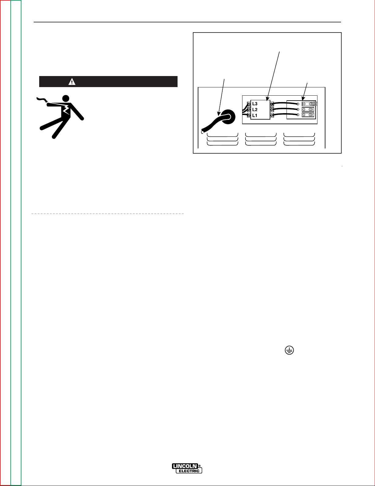
Input power supply entry is through the hole in the
Case Back Assembly. See Figure A.1 for the location
of the machine’s input cable entry opening, Input
Contactor (CR1), and reconnect panel.
FUSE AND WIRE SIZES
Protect the input circuit with the super lag fuses or
delay type circuit breakers listed on the Technical
Specifications page of this manual for the machine
being used. They are also called inverse time or thermal/magnetic circuit breakers.
DO NOT use fuses or circuit breakers with a lower amp
rating than recommended. This can result in “nuisance” tripping caused by inrush current even when
machine is not being used for welding at high output
currents.
GROUND CONNECTION
Ground the frame of the machine. A ground
terminal marked with the symbol is located inside
the case back of the machine near the input contactor.
Access to the input box assembly is at the upper rear
of the machine. See your local and national electrical
codes for proper grounding methods. Use grounding
wire sizes that meet local electrical codes or see the
Technical Specifications page in this manual.
INSTALLATION
A-4 A-4
IDEALARC DC-655
Return to Section TOC Return to Section TOC Return to Section TOC Return to Section TOC
Return to Master TOC Return to Master TOC Return to Master TOC Return to Master TOC
WARNING
FIGURE A.1 - ELECTRICAL INPUT CONNECTIONS
INPUT
CONTACTOR (CR1)
INPUT POWER SUPPLY
CABLE WITH BUSHING
OR BOX CONNECTOR
RECONNECT
PANEL ASSEMBLY
Page 11
INPUT POWER SUPPLY CONNECTIONS
A qualified electrician should connect the input power
supply leads.
1. Follow all national and local electrical codes.
2. Use a three-phase line.
3. Remove the input access door at upper rear of the
machine.
4. Follow input supply connection diagram located
on the inside of the door.
5. Connect the three-phase AC power supply leads
L1, L2, and L3 to the input contactor
terminals in the input box assembly. See Figure
A.1.
RECONNECT PROCEDURE
Electric Shock Can Kill
• Disconnect input power before performing this procedure.
Multiple voltage machines are shipped connected to
the highest input voltage listed on the machine’s rating
plate. Before installing the machine, check that the
reconnect panel in the input box assembly is connected for the proper voltage.
Failure to follow these instructions can cause immediate failure of components within the machine.
To reconnect a multiple voltage machine to a different
voltage, remove input power and follow the input connection diagram located on the inside of case back
input access door.
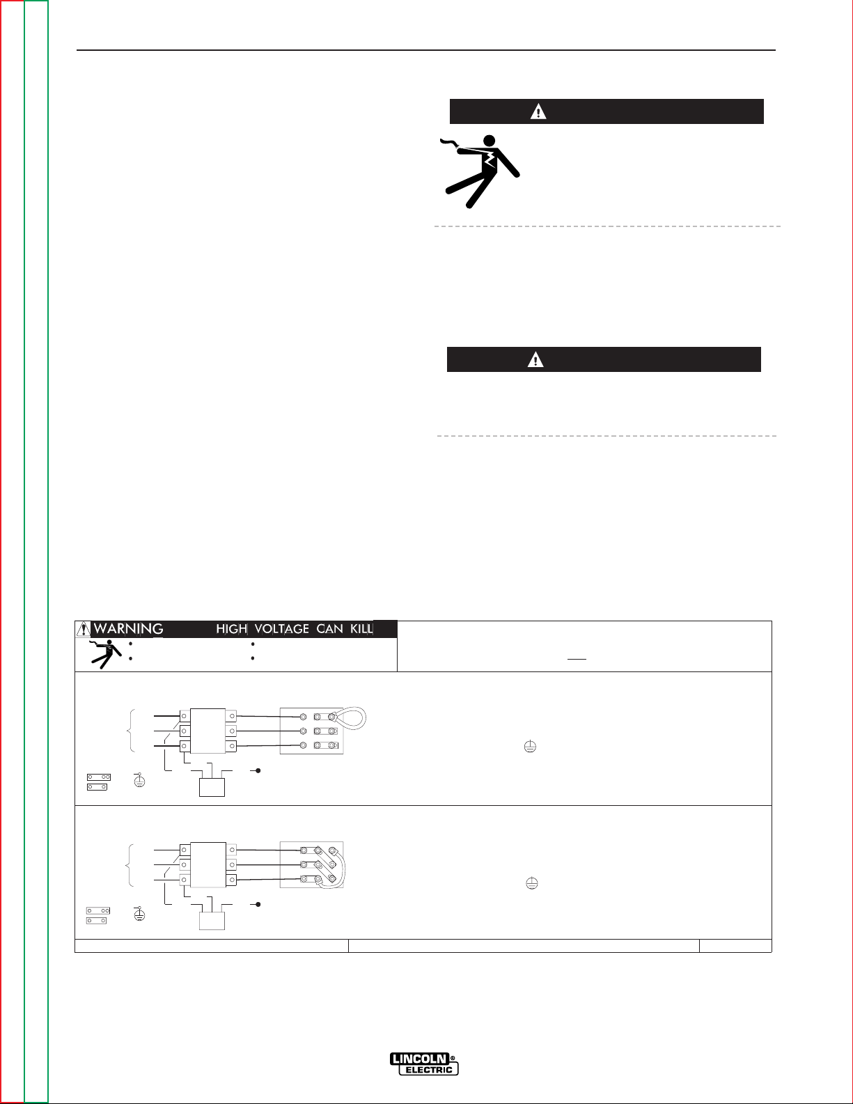
1. For dual voltage sample machine reconnect
instructions, see Figure A.2.
INSTALLATION
A-5 A-5
IDEALARC DC-655
Return to Section TOC Return to Section TOC Return to Section TOC Return to Section TOC
Return to Master TOC Return to Master TOC Return to Master TOC Return to Master TOC
WARNING
1. TURN OFF THE INPUT POWER USING THE DISCONNECT SWITCH AT THE FUSE BOX.
H2
GND
5. MOUNT THE LINKS IN THE POSITIONS SHOWN. CONNECT THE FLEX LEAD AS SHOWN;
LEADS TO THE INPUT SIDE OF CR1 CONTACTOR AS SHOWN.
L1
LINES
4. CONNECT TERMINAL MARKED TO GROUND PER LOCAL AND NATIONAL ELECTRIC
2. DISCONNECT AND INSULATE THE H3 LEAD TERMINAL WITH TAPE TO PROVIDE AT
LEAST 600 VOLT INSULATION.
CODES.
INSTALL AND TIGHTEN ALL OF THE HEX NUTS.
POSITIONING THE LUGS TO MAINTAIN MAXIMUM CLEARANCE TO THE LINKS.
D-UF
INPUT
3. CONNECT L1, L2 & L3 INPUT SUPPLY LINES AND H1 & H2 CONTROL TRANSFORMER
W
CR1
V
L3
U
H3
CONTACTOR
L2
L1
W
V
GND
CR1
L3
L2
1. TURN OFF THE INPUT POWER USING THE DISCONNECT SWITCH AT THE FUSE BOX.
2. DISCONNECT AND INSULATE THE H2 LEAD TERMINAL WITH TAPE TO PROVIDE AT
LEAST 600 VOLT INSULATION.
ALL OF THE HEX NUTS.
4. CONNECT TERMINAL MARKED TO GROUND PER LOCAL AND NATIONAL ELECTRIC
CODES.
5. MOUNT THE LINKS IN THE POSITIONS SHOWN; DOUBLE OR TRIPLE STACK THE LINKS
IN THREE POSITIONS. LOOP THE FLEX LEAD IN THE POSITION SHOWN; POSITIONING
THE LUGS TO MAINTAIN MAXIMUM CLEARANCE TO THE LINKS. INSTALL AND TIGHTEN
DUAL VOLTAGE MACHINE
INPUT SUPPLY CONNECTION DIAGRAM
IMPORTANT: CHANGE LINK POSITIONS AND CONTROL TRANSFORMER CONNECTIONS.
NOTE: MACHINES ARE SHIPPED FROM FACTORY CONNECTED FOR OVER 300 VOLTS
Do not touch electrically live parts
Only qualified persons should install,
use or service this equipment
Do not operate with covers
removed
Disconnect input power before
LEADS TO THE INPUT SIDE OF CR1 CONTACTOR AS SHOWN.
TRANSF.
CONTROL
TRANSF.
CONTROL
3. CONNECT L1, L2 & L3 INPUT SUPPLY LINES AND H1 & H3 CONTROL TRANSFORMER
CONNECTION FOR HIGHEST RATING PLATE VOLTAGE
servicing
M18225
INPUT
CONTACTOR
CONNECTION FOR LOWEST RATING PLATE VOLTAGE
H2
H1
LINKS
LINES
THE LINCOLN ELECTRIC CO., CLEVELAND OHIO U.S.A.
LINKS
U
H1
H3
FIGURE A.2 - DUAL VOLTAGE MACHINE RECONNECTION PROCEDURE
CAUTION
Page 12
OUTPUT CONNECTIONS
ELECTRODE AND WORK CABLES
Use the shortest possible cable lengths. See Table A.1
for recommended cable sizes based on length.
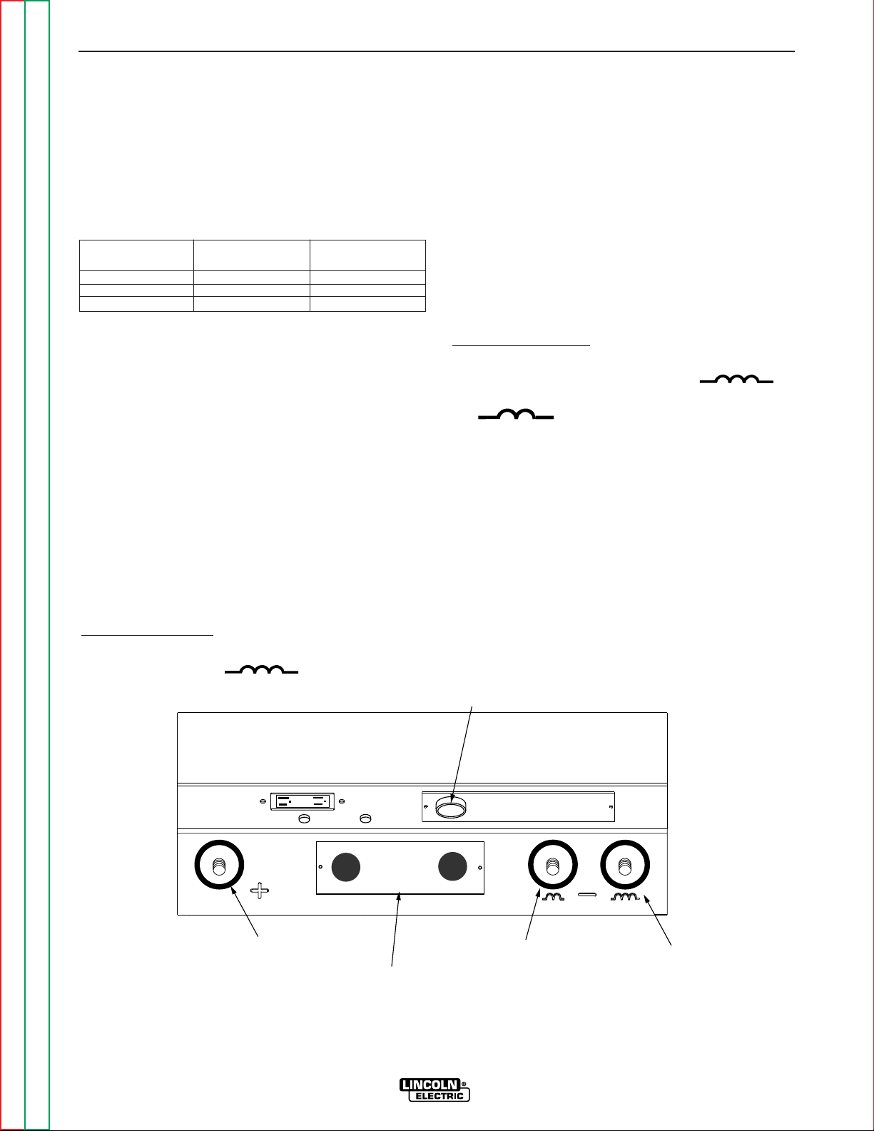
The output terminals are located at the lower front of
the welder behind a hinged door. Refer to Figure A.3.
Route the welding cables through the slotted strain
reliefs of the base to the welding terminals.
LOW INDUCTANCE TERMINAL
On the DC-655, the inside right Negative (-) output terminal is lower choke inductance. This terminal is
presently only recommended for CV mode welding
with NR203Ni 1% negative polarity procedures.. All
other processes are to be welded using the outside
right Negative (-) output terminal with higher choke
inductance. CC mode processes must use high
inductance.
For Positive Polarity:
1. Connect the work cable to the high inductance (-)
terminal (marked " ").
2. Connect the electrode cable to the positive terminal
marked “+”.
3. Remove the terminal strip access cover panel on
the lower case front. Refer to Figure A.3 for the
location.
4. Work Sense lead #21 from the 14 Pin MS-receptacle must be connected to “-21”on the terminal strip.
Note: This is how the DC-655 is shipped from the
factory.
5. Replace the terminal strip access cover panel.
For Negative Polarity:
1. Connect the electrode cable to the appropriate high
inductance (-) terminal (marked " ")
or to the low inductance (-) terminal (marked
" ") if using NR203Ni 1% electrode.
2. Connect the work cable to the positive terminal
marked “+”.
3.
Remove the terminal strip access cover panel on the
lower case front. Refer to Figure A.3 for the location.
4. Work Sense lead #21 from the 14 Pin MS-receptacle must be connected to “+21”on the terminal
strip.
5. Replace the terminal strip access cover panel.
INSTALLATION
A-6 A-6
IDEALARC DC-655
Return to Section TOC Return to Section TOC Return to Section TOC Return to Section TOC
Return to Master TOC Return to Master TOC Return to Master TOC Return to Master TOC
TABLE A.1
Cable Sizes for Combined Lengths of Copper
Electrode and Work Cable
Cable Length
ft. (m)
Parallel Cables Cable Size
0 (0) to 100 (30.4)
100 (30.4) to 200 (60.8)
200 (60.8) to 250 (76.2)
2
2
2
2/0 ( 70mm2)
3/0 ( 95mm2)
4/0 (120mm2)
FIGURE A.3 - OUTPUT CONNECTIONS
POSITIVE
OUTPUT
TERMINAL
TERMINAL STRIP
COVER PANEL
14 PIN MS RECEPTACLE
LOW INDUCTANCE
NEGATIVE OUTPUT
TERMINAL
HIGH INDUCTANCE
NEGATIVE OUTPUT
TERMINAL
Page 13
Return to Section TOC Return to Section TOC Return to Section TOC Return to Section TOC
Return to Master TOC Return to Master TOC Return to Master TOC Return to Master TOC
INSTALLATION
A-7 A-7
IDEALARC DC-655
AUXILIARY POWER AND
CONTROL CONNECTIONS
Located at the lower front of the welder behind a
hinged door is a 115 VAC duplex receptacle for auxiliary power (Domestic and Canadian Models only) and
a 14-pin MS type receptacle for connection of auxiliary
equipment such as wire feeders. Also, terminal strips
with 115 VAC and connections for auxiliary equipment
are located behind the access panel on the lower case
of the welder. A 220 VAC receptacle for a water cooler
(European and Export Models only) is located on the
case back.
115 VAC DUPLEX RECEPTACLE (DOMESTIC AND
CANADIAN MODELS ONLY)
The 115 VAC duplex receptacle is protected by a circuit breaker located below the receptacle (see
Auxiliary Power Table). Receptacle is a NEMA 5-20R
(protected by a 20 amp breaker) on Domestic Models
and a NEMA 5-15R (protected by a 15 amp breaker) on
Canadian Models.
230 VAC RECEPTACLE (EUROPEAN AND EXPORT
MODELS ONLY)
A Continental European receptacle is located on the
rear panel for supplying 220 VAC to a water cooler. The
receptacle has a protective cover to prevent accidental contact and is a Schuko type. The circuit is protected by a 2 amp circuit breaker also located on the
rear panel. This circuit is electrically isolated from all
other circuits, but on the European Models one line is
connected to chassis ground.
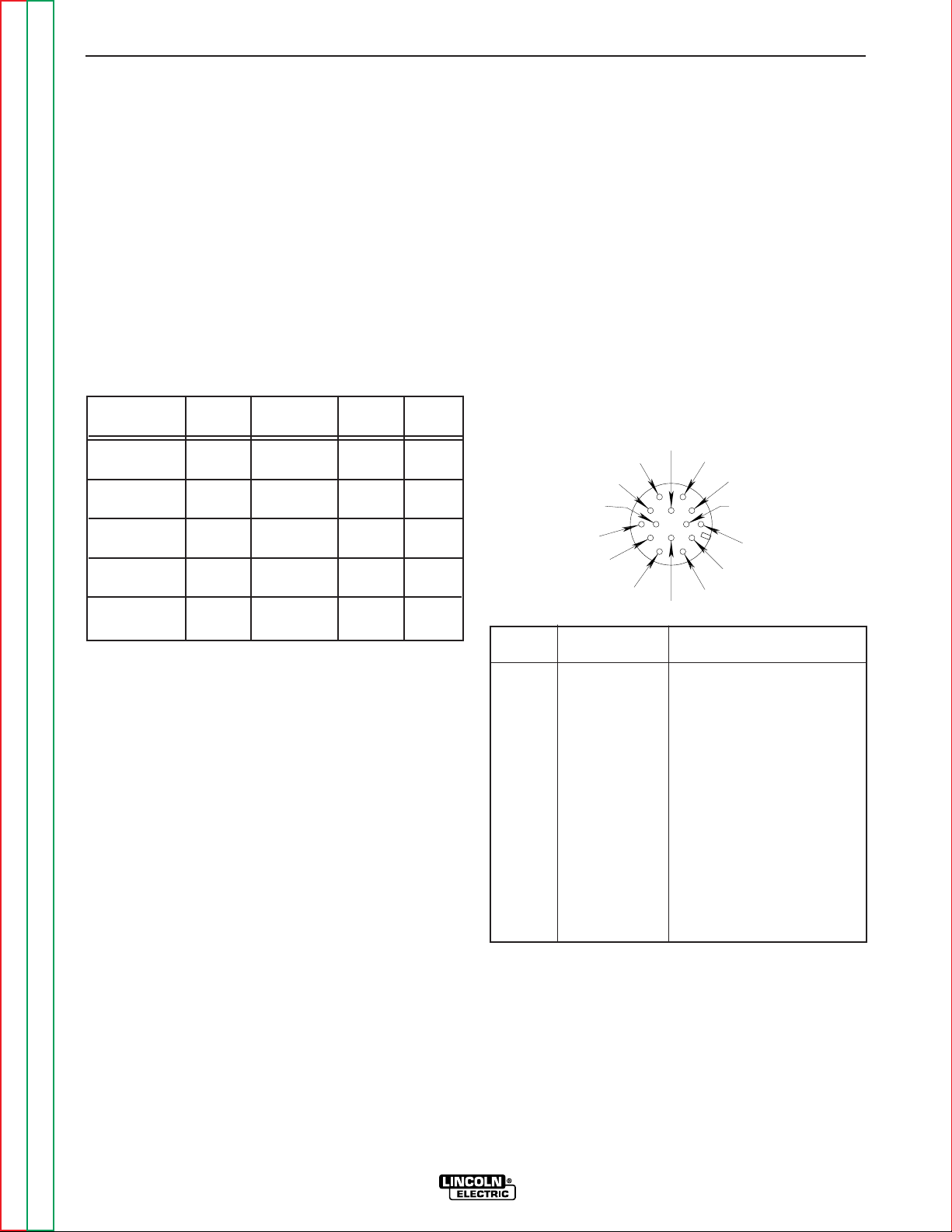
14-PIN MS TYPE RECEPTACLE
(For MS3106A-20-27PX Plug. L.E.C. Part #S12020-32)
Refer to the Figure A.4 for the available circuits in the
14-pin receptacle.
42 VAC is available at receptacle pins I and K. A 10
amp circuit breaker protects this circuit.
115 VAC is available at receptacle pins A and J
(Domestic, Canadian and Export Models). This circuit
is protected by a circuit breaker (see Auxiliary Power
Table). Note that the 42 VAC and 115 VAC circuits are
electrically isolated from each other. However, on the
European model one line of the 115 VAC is connected
to chassis ground.
AUXILIARY POWER TABLE
Voltage and Circuit Breaker Ratings at Auxiliary Power
Connections for Various Models
Auxiliary Domestic Canadian European Export
Power Models Model Models Models
Connections (60Hz)
(230/460/575V/60 Hz)
(50/60 Hz) (50/60 Hz)
At Duplex 115V 20A 115V 15A No Duplex No Duplex
Receptacle
Terminal strip 115V 20A 115V 15A 115V 15A 115V 15A
terminals 31 & 32
MS-Receptacle 115V 20A 115V 15A
Open Circuit
115V 15A
pins A & J
MS-Receptacle 42V 10A 42V 10A 42V 10A 42V 10A
pins I & K
At 220V
No Receptacle No Receptacle 220V 2A 220V 2A
Receptacle
FIGURE A.4 - FRONT VIEW OF 14-PIN
CONNECTOR RECEPTACLE
PIN LEAD NO. FUNCTION
A 32 115 VAC
B GND Chassis Connection
C 2 Trigger Circuit
D 4 Trigger Circuit
E 77 Output Control
F 76 Output Control
G 75 Output Control
H 21 Work Sense Connection
2
I 41 42 VAC
J 31 115 VAC
1.
K 42 42 VAC
L --- --M --- --N --- ---
1.
115VAC circuit is not present in the 14-pin connector on IEC 9741 European models.
2.
As shipped from the factory Lead #21 from the 14-pin connector is
connected to “-21”on the terminal strip. This is the configuration for
positive welding. If welding negative polarity, connect lead #21 to
the “+21”connection point on the ter minal strip.
K=42
A=32
B=GND
L N
C=2
D=4
E=77
J=31
I=41
H=21
G=75
F=76
M
Page 14

TERMINAL STRIPS
Terminal strips are available behind the cover panel on
the lower case front to connect wire feeder control
cables that do not have a 14-Pin MS-type connector.
Refer to Figure A.3 for the location of this cover panel.
These terminals supply the connections as shown in
the following Terminal Strip charts. See Auxiliary
Power Table for rating of circuit breaker in 115 VAC circuit. Remove a plug button from the terminal strip
cover and install an appropriate strain relief clamp for
the cable being used. NOTE: There are two work
sense lead connection points on the terminal strip.
Connect both the work sense lead #21 from the 14-pin
connector and #21 lead of the control cable to “-21”
when welding positive polarity or to “+21” when welding negative polarity.
TERMINAL STRIP 1 (T.S.1)
TERMINAL STRIP 2 (T.S.2)
INSTALLATION
A-8 A-8
IDEALARC DC-655
Return to Section TOC Return to Section TOC Return to Section TOC Return to Section TOC
Return to Master TOC Return to Master TOC Return to Master TOC Return to Master TOC
Lead No. Function
75 Output Control
76 Output Control
77 Output Control
1
115 VAC circuit is also present on IEC 974-1 European models.
2
If connecting a feeder cable directly to the terminal strip, Lead #21
from the cable is connected to “-21”on the terminal strip for positive
welding. If welding negative polarity, connect lead #21 to the “+21”
connection point on the terminal strip.
Lead No. Function
+21 Work Connection
-21 Work Connection
2
41 42 VAC
4 Trigger Circuit
2 (42 VAC) Trigger Circuit (42 VAC)
31 115 VAC
1
32 115 VAC
1
Page 15

Return to Master TOC Return to Master TOC Return to Master TOC Return to Master TOC
Section B-1 Section B-1
IDEALARC DC-655
TABLE OF CONTENTS
- OPERATION SECTION -
Operation...............................................................................................................................Section B
Safety Precautions......................................................................................................................B-2
General Description ....................................................................................................................B-3
Recommended Processes and Equipment .........................................................................B-3
Design Features and Advantages ........................................................................................B-3
Welding Capability................................................................................................................B-3
Controls and Settings.................................................................................................................B-4
Case Back Connections .............................................................................................................B-6
220 VAC Auxiliary Receptacle..............................................................................................B-6
220 VAC 2 Amp Circuit Breaker...........................................................................................B-6
Auxiliary Power ...........................................................................................................................B-6
Machine Protection.....................................................................................................................B-6
Thermal Fan Control.............................................................................................................B-6
Fan Motor Fuse ....................................................................................................................B-6
Machine Shutdown ..............................................................................................................B-6
Thermal Shutdown ...............................................................................................................B-7
Over Current Protection Shutdown......................................................................................B-7
Remote Control Leads Fault Protection Shutdown.............................................................B-7
Shorted Rectifier Fault Protection........................................................................................B-7
Idle Shutdown Timer ............................................................................................................B-7
Welding Performance .................................................................................................................B-8
Low Inductance Terminal .....................................................................................................B-8
CV Mode Current Limiting....................................................................................................B-8
CC Mode Arc Force .............................................................................................................B-8
CC Mode Hot Start ..............................................................................................................B-8
CC Mode Arc Gouging.........................................................................................................B-8
Page 16
Return to Section TOC Return to Section TOC Return to Section TOC Return to Section TOC
Return to Master TOC Return to Master TOC Return to Master TOC Return to Master TOC
B-2
B-2
IDEALARC DC-655
OPERATING INSTRUCTIONS
Read and understand this entire section of operating
instructions before operating the machine.
SAFETY PRECAUTIONS
ELECTRIC SHOCK can kill.
• Do not touch electrically live parts or
electrodes with your skin or wet clothing.
• Insulate yourself from the work and ground.
• Always wear dry, insulating gloves.
FUMES AND GASES can be
dangerous.
• Keep your head out of fumes.
• Use ventilation or exhaust to remove fumes from
breathing zone.
CUTTING SPARKS can cause
fire or explosion.
• Keep flammable material away.
• Do not cut containers that have held combustibles.
ARC RAYS
can burn.
• Wear eye, ear, and body protection.
Observe additional Safety Guidelines detailed in
the beginning of this manual.
WARNING
OPERATION
Page 17

GENERAL DESCRIPTION
The DC-655 is an energy efficient constant voltage DC
power source that produces outstanding arc characteristics for multiple CV or CC welding processes.
Four models are available:
Domestic - all 60 Hertz models except
230/460/575v.
NEMA Class 1 rated
Canadian - 230/460/575v 60 Hertz
NEMA Class 1 rated
European - 50/60 Hertz models “CE” qualified
and rated for IEC 974-1
Export - 50/60 Hertz models NEMA Class 1 rated
RECOMMENDED PROCESSES AND
EQUIPMENT
The DC-655 is designed for CV or CC processes.
CV processes include: GMAW (MIG) and FCAW (fluxcored) welding, plus the capability of CV submerged
arc welding and air carbon arc gouging. It produces
outstanding welding performance with a single range
full output control knob.
CC processes include stick welding, CC submerged
arc and superior air carbon arc gouging with up to 3/8”
(10 mm) diameter carbons. The same single range full
output control knob is used and paralleling capability
is provided.
The DC-655 is recommended for use with Lincoln’s
DH-10 or LN-10 as well as the LN-7*, LN-7 GMA*, LN742, LN-8*, LN-9*, LN-9 GMA*, LN-23P and LN-25
semiautomatic wire feeders. It is also recommended
for use with the NA-3, NA-5 and NA-5R automatic
feeders. “Cold starting” for sub-arc or across arc
“touch-sensing” can be used.
* The 14-pin MS receptacle on the European models
does not provide 115 VAC for these feeders; 115
VAC must be obtained from terminal strip.
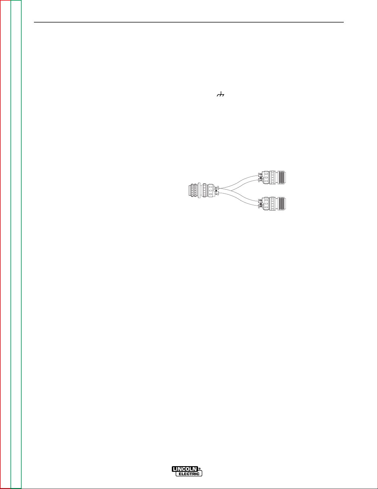
Two DC-655’s may be paralleled in a “master” and
“slave” interconnection using the K1611-1 Paralleling
kit.
DESIGN FEATURES AND
ADVANTAGES
• Separate output terminals for selecting high or low
inductance as recommended for the welding
process.
• Power on/off switch with pilot light and thermostat
tripped indicator light.
• Full range output voltage (CV mode) and current (CC
mode) control for easy operation.
• Panel switches behind a latched front panel for
remote or local output control, output on or remote
selection, and CC, CV Sub-arc or CV MIG mode
selection.
• Panel knob settable CC arc force control with builtin adjustable “Hot Start”.
• High efficiency output, and selectable “sleep mode”
idle mode timer which shuts down input power if not
used for extra energy conservation.
• Fan as needed (F.A.N.). Solid state thermally controlled fan operates cooling fan only when required.
Minimizes power consumption, operating noise and
dust intake.
• Hinged cover to protect output terminals and auxiliary connections.
• Electronic and thermostatic protection for current
overload and excessive temperatures.
• 42 VAC, 10 amp auxiliary power available for the wire
feeder; circuit breaker protected.
• 115 VAC, auxiliary power available for the wire feeder; circuit breaker protected. 20 amp breaker on
Domestic model and 15 amp breaker on Canadian,
European, and Export Models.
• 115 VAC duplex plug receptacle available on
Domestic and Canadian Models. 20 amp breaker on
Domestic Models and 15 amp breaker on Canadian
Model.
• 220 VAC receptacle on European and Export models
for connecting to a water cooler. Protected by 2 amp
breaker.
• Single MS-type (14-pin) connection for wire feeder.
• Optional Field Installed Digital or Analog Voltmeter/
Ammeter kits are available.
• Optional dual feeder kit for like polarity connection of
two wire feeders. Easy panel installation.
• Optional Dual Process Switch for two processes
with polarity change and electrical isolation.
WELDING CAPABILITY
The DC-655 has the following Output and Duty Cycle
based on operation for a 10 minute period:
650 Amps, 44 Volts at 100%
815 Amps, 44 Volts at 60%
OPERATION
B-3 B-3
IDEALARC DC-655
Return to Section TOC Return to Section TOC Return to Section TOC Return to Section TOC
Return to Master TOC Return to Master TOC Return to Master TOC Return to Master TOC
Page 18
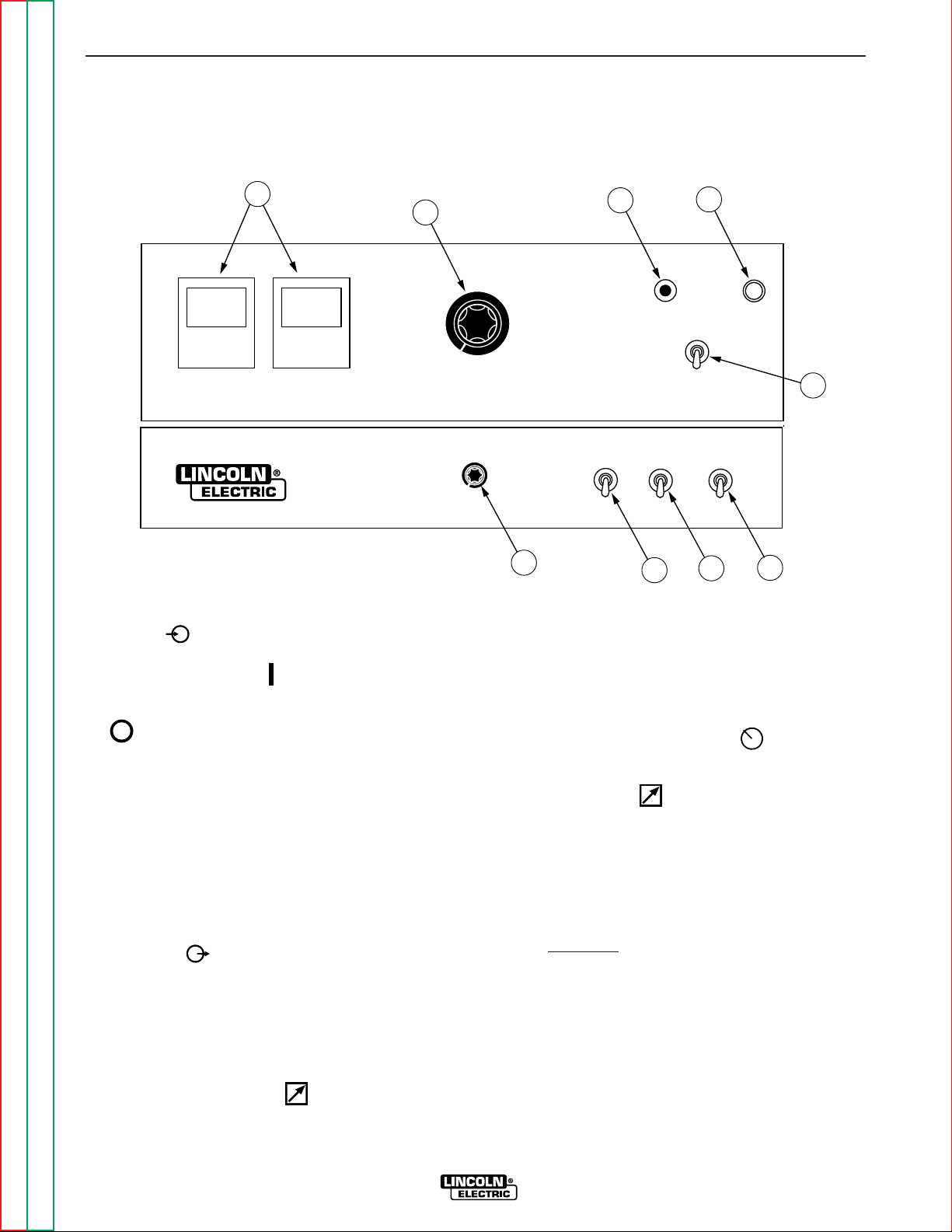
1. INPUT POWER ON/OFF SWITCH - This tog-
gle switch turns the machine on or off. Putting the
switch in the ON position energizes the
machine’s input contactor applying input power to
the machine. Switching the switch to the OFF
position de-energizes the input contactor. This
switch is also used to reset a machine shutdown.
(See Machine Shutdown section)
2. PILOT LIGHT - When the power switch is in the
ON position the machine’s white pilot light will illuminate. If the input contactor de-energizes the
machine in a shutdown situation, the pilot will still
illuminate. In this situation it will be necessary to
reset the machine by switching the power switch to
the OFF then ON position. (See Machine
Shutdown section)
3. OUTPUT CONTROL - This control provides
continuous control of the machine’s output from
minimum to maximum as it is rotated clockwise.
The CV mode voltage range of control is 13 to 44V.
The CC mode current range of control is 50 to
815A.
4. OUTPUT TERMINALS ON/REMOTE - When this
switch is in the REMOTE position, the DC-655’s
output terminals will be electrically “cold” until a
remote device such as a wire feeder closes the #2 and
#4 circuit in the MS-receptacle or terminal strip. When
this switch is in the ON position the machine’s output
terminals will be electrically energized all the time.
5. LOCAL/REMOTE CONTROL SWITCH - When
this switch is set to the LOCAL position, control of the output voltage is via the output control
on the DC-655’s control panel. When this switch is
set to the remote position, control is through a
remote source such as a wire feeder via the #75,
#76, and #77 leads in the MS-receptacle or terminal strip.
6.
CC STICK/CV SUBARC/CV MIG MODE SWITCH -
This switch selects the proper welding characteristics for the process being used:
CC Stick provides a constant current output
characteristic through the 50 to 815 amp
range. The current is adjusted within this
range by the Output Control dial. The open
circuit (no load) voltage will be about 68 volts
in this mode.
This mode is used for stick welding (SMAW)
and CC air carbon-arc gouging, and employs
a “Hot Start” feature and an Arc Force Control.
OPERATION
B-4 B-4
IDEALARC DC-655
Return to Section TOC Return to Section TOC Return to Section TOC Return to Section TOC
Return to Master TOC Return to Master TOC Return to Master TOC Return to Master TOC
CONTROLS AND SETTINGS
All operator controls and adjustments are located on the case front of the DC-655. Refer to Figures B.1, and B.2
and corresponding explanations.
FIGURE B.1 CONTROL PANEL CONTROLS
DC-655
5
4
8
1
9
2
3
6
7
Page 19
Return to Section TOC Return to Section TOC Return to Section TOC Return to Section TOC
Return to Master TOC Return to Master TOC Return to Master TOC Return to Master TOC
OPERATION
B-5 B-5
IDEALARC DC-655
CC mode may also be used for CC submerged arc
with appropriate arc-sensing CC(VV) wire feeders
if arc force is set high enough. Refer to Welding
Performance section.
CV MIG provides a constant voltage output characteristic through the 13 to 44 volt range. The voltage is adjusted within this range by the Output
Control dial.
The dynamic characteristics of this mode are ideal
for open arc processes including, MIG/MAG
(GMAW), Innershield®, and other cored wire
(FCAW) processes. Faster travel submerged arc
processes and CV air carbon-arc gouging may
also use this mode. Refer to the Welding
Performance section.
CV Sub-Arc provides the same constant voltage
output control range as CV MIG, but the dynamic
characteristics of this mode make possible
improved CV (constant wire speed) submerged arc
welding. This improved process is most noticeable on high deposition slow travel speed welds.
Fast travel, narrow bead subarc welds will have
better performance in CV MIG mode.
7. ARC FORCE CONTROL - This control is only func-
tional in CC Stick mode. It prevents “stubbing” of
the electrode by providing the extra weld current
that linearly increases as the welding voltage
decreases below a level determined by the setting
of the constant current control.
The Arc Force control knob, located behind the
latched cover, adjusts arc force from “Min” (no current increase) to “Max” (higher short circuit current).
The “mid” position (#5) is recommended for most
CC welding. Refer to the Welding Performance
Section.
8. OPTIONAL VOLTMETER & AMMETER - Digital or
analog meter kits are available as field installed
options. Refer to the Accessories Section of this
manual.
9. THERMAL PROTECTION LIGHT - If the
machine overheats due to lack of proper air flow
through the machine or due to exceeding the
machine’s duty cycle, thermostats will disable the
welding output and this light will illuminate. Input
power is still applied to the machine and the cooling fan will continue to run. When the machine
cools the welding output will resume.
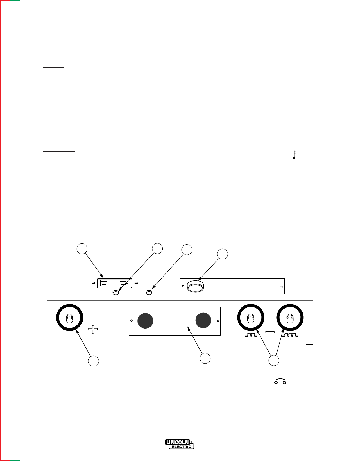
FIGURE B.2 LOWER CASE FRONT CONTROLS & CONNECTIONS
7
6
5
4
3
1 2
1. 115 VAC DUPLEX RECEPTACLE (Domestic and
Canadian Models) This receptacle provides up to
20 amps of 115 VAC auxiliary power on the
Domestic Models and up to 15 amps on the
Canadian Model.
2. 115 VAC CIRCUIT BREAKER - This breaker
protects the 115 VAC auxiliary circuits located in
the duplex receptacle, terminal strip and MSreceptacle. Breaker is rated 20 amps on Domestic
Models and 15 amps on all other models.
Page 20

3. 42 VAC 10 AMP CIRCUIT BREAKER - This
breaker protects the 42 VAC auxiliary circuits located in the terminal strip and MS-receptacle.
4. 14-PIN MS-RECEPTACLE - This connector provides easy connection for a wire feeder control
cable. It provides connections for auxiliary power,
output switching, remote output control, wire feeder voltmeter sense lead and ground. Refer to 14-
Pin MS Type Receptacle in the Installation
Section of this manual for information about the circuits made available at this receptacle.
5. TERMINAL STRIP COVER PANEL - Remove this
panel to gain access to the circuits made available
at the terminal strip and the 4-pin receptacle for the
optional paralleling kit. This terminal strip contains
the same circuits as the 14-pin MS-receptacle.
The cover also provides for installation of cable
strain relief clamps.
6. POSITIVE OUTPUT TERMINAL - This output terminal is for connecting a welding cable. To change
welding polarity and for proper welding cable size
refer to Electrode and Work Cables in the
Installation Section of this manual.
7. NEGATIVE OUTPUT TERMINALS - These output
terminals are for connecting a welding cable to
either the High Inductance or Low Inductance
Terminal for desired arc characteristics. To change
welding polarity and for proper welding cable size
refer to Electrode and Work Cables in the
Installation Section of this manual.
CASE BACK CONNECTIONS
220 VAC AUXILIARY RECEPTACLE
(European and Export Models)
This receptacle provides up to 2 amps of 220 VAC
auxiliary power for a water cooler.
220 VAC 2 AMP CIRCUIT BREAKER
(European and Export Models)
This breaker protects the 220 VAC auxiliary circuit
located in the 220 VAC receptacle.
AUXILIARY POWER
42 volt AC auxiliary power, as required for some wire
feeders, is available through the wire feeder receptacle. A 10 amp circuit breaker protects the 42 volt circuit from overloads.
DC-655 machines can also supply 115 volt AC auxiliary power through the wire feeder receptacle. A 20
amp circuit breaker on the Domestic model, and a 15
amp on the Canadian and Export models protects the
115 volt circuit from overloads. 115 VAC is not available in the MS-receptacle on the European models.
Note that some types of equipment, especially pumps
and large motors, have starting currents which are significantly higher than their running current. These higher starting currents may cause the circuit breaker to
open. If this situation occurs, the user should refrain
from using the DC-655 auxiliary power for that equipment.
MACHINE PROTECTION
THERMAL FAN CONTROL
The machine’s cooling fan remains off when the temperature of the rectifiers and windings inside the
machine are below that requiring air flow cooling, as
determined by electronic monitoring of several thermal
sensors and the welding current of the machine.
Depending upon the operating temperature of the
machine, the fan may remain off while welding but
once the fan is activated, it will remain on for at least 5
minutes to assure proper cooling. This feature saves
energy and also minimizes the amount of dirt and
other air borne particles being drawn into the machine.
FAN MOTOR FUSE
(European Model)
A 10 amp slow blow fuse protects the fan motor circuit. This fuse is located inside the DC-655 mounted
on the fan motor bracket.
MACHINE SHUTDOWN
The DC-655 provides shutdown modes for thermal
over-heating, excessive load currents and faults. It
also provides an idle timer shutdown feature for additional operating economy.
OPERATION
B-6 B-6
IDEALARC DC-655
Return to Section TOC Return to Section TOC Return to Section TOC Return to Section TOC
Return to Master TOC Return to Master TOC Return to Master TOC Return to Master TOC
CAUTION
Page 21
THERMAL SHUTDOWN
This welder has thermostatic protection from excessive duty cycles, overloads, loss of cooling, and high
ambient temperature. When the welder is subjected to
an overload or loss of cooling, a thermostat will open.
This condition will be indicated by the illumination of
the yellow Thermostatic Protection Light on the case
front (see Figure B.1). The fan will continue to run to
cool the power source. No welding is possible until the
machine is allowed to cool and the Thermostatic
Protection Light goes out.
OVER CURRENT PROTECTION
SHUTDOWN
Average Current Shutdown
To protect the SCR’s , the DC-655 will shut down to
essentially no output if the output current averages
over 900 amps for about 5-6 seconds, and in less than
0.3 seconds if averaging over 1200 amps (shorter time
for higher current). Control PC board LED4, shutdown
light, will turn on.
This average current shut down can only be reset by
opening the feeder gun trigger, or switching the DC655 Output/Remote switch out of the “on” position.
Peak Current Shutdown
To protect the SCRs, the DC-655 will shut down immediately to essentially no output if the peak output current exceeds 2500 amps (about 1800A average).
Control PC board LED4, shutdown light, will turn on.
This peak current shut down can be reset by turning
the DC-655 input power off, then on.
REMOTE CONTROL LEADS FAULT
PROTECTION SHUTDOWN
1
The remote control leads from the 14-pin receptacle or
terminal strip are protected against high voltage faults
to the electrode circuit or auxiliary voltage supplies. If
such a fault occurs, the DC-655 will shut down the
input primary voltage to the transformer to prevent the
fault output. Control PC board LED3, input shutdown
light, turns on.
If this input shutdown occurs the input power pilot
light remains lit, since the power switch is ON and
control power is still present. Welding output or auxiliary supply output will not be present.
This input shut down is reset by turning the DC-655
input power off, then on. If the fault is not corrected
however, the shutdown will re-occur when turning on
the input power.
1
Note on earlier machines: LED4 will turn on and output will be
disabled if this fault occurs.
SHORTED RECTIFIER FAULT PROTECTION
If a short occurs across one of the silicon controlled
rectifiers of the DC-655, a potentially hazardous AC
voltage could appear across the welding output terminals, even in idle mode when no output should be present. If such a fault occurs, the DC-655 will shut down
the input primary voltage to the transformer to prevent
the fault output. Control PC board LED3, input shutdown light, turns on.
If this input shutdown occurs the input power pilot
light remains lit, since the power switch is ON and
control power is still present. Welding output or auxiliary supply output will not be present.
This input shut down is reset by turning the DC-655
input power off, then on. If the fault is not corrected
however, the shutdown will re-occur when turning on
the input power.
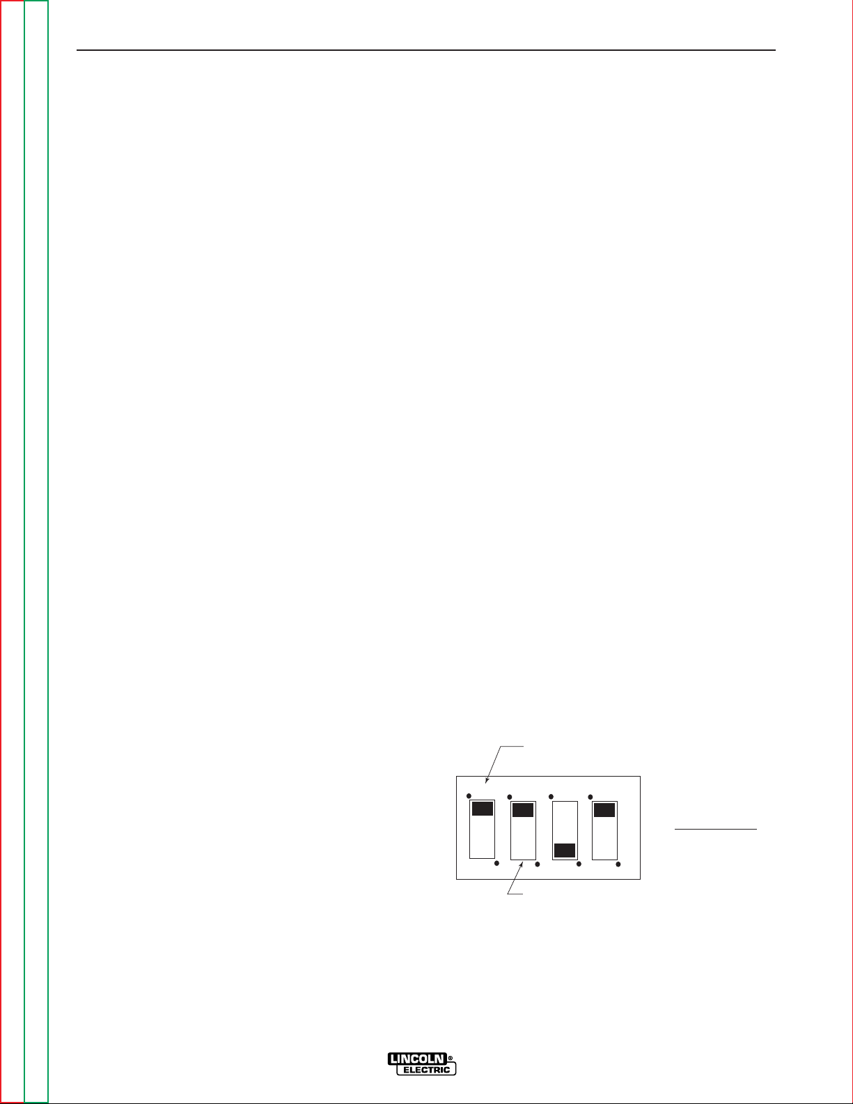
IDLE SHUTDOWN TIMER
For additional operating economy, the DC-655 can be
set up to automatically shut off the primary input
power to the main transformer after a selectable time
(1/2 or 2 hr.) has expired without welding. The unexpired timer is reset with each weld.
The idle mode timer is activated by setting Switch #1
(left most) of the DIP Switch located on the lower-center of the DC-655 Control PC board. from the down
(Off) position to the up (On) position. Setting Switch
#2 of the DIP switch to up (On) sets the shutdown time
to 2 hours. Setting Switch #2 of the DIP switch to
down (Off) sets the shutdown time to 1/2 hour.
Shutdown is reset by turning the DC-655 input power
off, then on.
OPERATION
B-7 B-7
IDEALARC DC-655
Return to Section TOC Return to Section TOC Return to Section TOC Return to Section TOC
Return to Master TOC Return to Master TOC Return to Master TOC Return to Master TOC
Switch #1 Timer On/Off
(UP=ON, Down=OFF)
1 2 3 4
DIP Switch
Switch #2 Time selection
(UP=2 hours, Down=1/2 hour)
See Weld Performance section
Note:
for use of switch #3 and #4.
Page 22
WELDING PERFORMANCE
LOW INDUCTANCE TERMINAL
The inside right Negative (-) terminal is lower choke
inductance and presently is only recommended for
welding with NR203Ni 1% procedures. All other
processes are to be welded using the outside right
Negative (-) terminal with higher choke inductance.
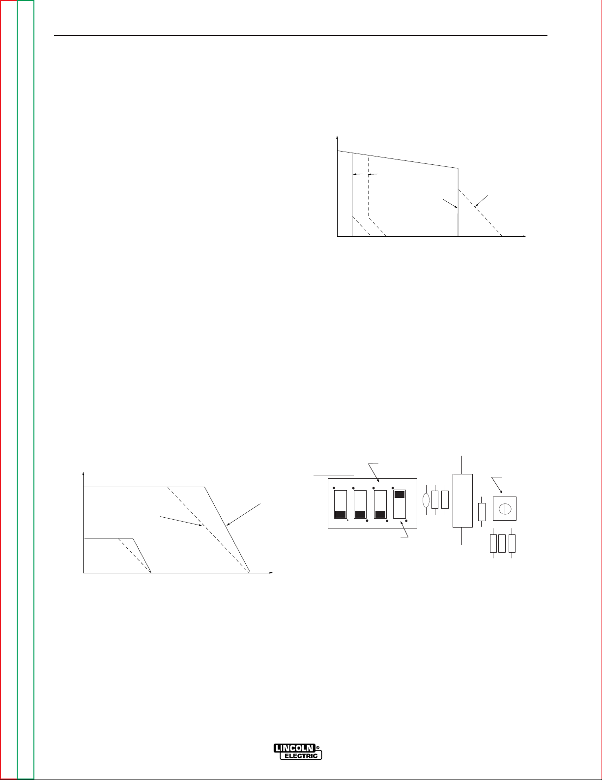
CV MODE CURRENT-LIMITING
CV MIG and CV Sub-Arc modes employ electronic
current limiting to limit excessive short circuit output
current which can result in undesirable arc characteristics or nuisance over current protection shutdown
(see Machine Protection section).
As shipped, the DC-655 is set for “Hi” current limiting,
which maintains constant voltage until the welding
current exceeds a level proportional to the voltage setting, then falls off linearly at about 10 volts per 100
amps to a limited short circuit current. “Lo” current
limiting provides the same short circuit current, but the
arc voltage begins to linearly fall off at lower current, at
about 5 volts per 100 amps.
“Hi” is recommended for all CV processes, especially
for CV subarc and CV arc gouging, but “Lo” tends to
“soften” the arc more when welding NR203Ni 1% on
the Low Inductance (-) terminal. If “Lo” is desired,
switch #4(right-most) of the DIP switch located on the
lower-center of the DC-655 Control PC board needs to
be switched from up (Hi) position to down (Lo) position.
CC MODE ARC FORCE
Arc Force provides extra weld current which linearly
increases as the welding voltage decreases below a
level determined by the constant current setting. The
Arc Force control knob, located behind the latched
cover, adjust Arc Force from “Min” (no current
increase) to “Max” (about 9A/V increase).
As a general guideline for CC welding, set Arc Force to
“Mid” position and increase (typically to no more than
#7) as necessary to prevent “stubbing” or “pop-outs”
while welding. This higher arc force is recommended
especially for low end 6010 stick welding.
CC MODE HOT START
Hot start is built-in for CC mode stick and carbon arc
starting. Hot Start provides an extra weld current
“boost” at the arc strike which increases with higher
current settings. This Hot Start level exponentially
decays to the weld current setting in a few seconds.
Adjustment of the Hot Start shouldn’t be necessary,
but an unsealed trimmer (R81) is provided on the DC655 Control PC Board to adjust hot start. Full counterclockwise adjustment will reduce Hot Start to zero.
CC MODE ARC GOUGING
The DC-655 is rated for air carbon arc gouging with up
to 3/8” (10mm) diameter carbons. CC mode gouging
is often preferred over CV mode for cutting control, but
some Arc Force may be required to avoid carbon stubbing.
OPERATION
B-8 B-8
IDEALARC DC-655
Return to Section TOC Return to Section TOC Return to Section TOC Return to Section TOC
Return to Master TOC Return to Master TOC Return to Master TOC Return to Master TOC
VOLTS
OCV
Hot Start
Max. Arc Force
AMPS
Low
Setting
Min. Arc Force
Hi
Setting
CC OUTPUT
VOLTS
High
Setting
Low
Setting
"Lo" Current Limit
CV OUTPUT
"HI" Current Limit
AMPS
Switch #3 is for test
purposes. Keep down.
DIP Switch
1 2 3 4
Switch #4 "Hi"CV Current
Limit (as shown)
(as shown)
See Machine Shutdown section
Note:
for use of switch #1 and #2.
CC Hot Start
Trimmer
DC-655 Control PC Board
Page 23

TABLE OF CONTENTS
- ACCESSORIES -
Accessories...........................................................................................................................Section C
Field Installed Options................................................................................................................C-2
Connection of Lincoln Electric Automatic or Semiautomatic Wire Feeders..............................C-3
Automatic Wire Feeders.......................................................................................................C-3
NA-3 or LT-7 (Terminal Strip) .........................................................................................C-3
NA-5 or NA-5R (Terminal Strip) .....................................................................................C-4
Semiautomatic Wire Feeders...............................................................................................C-6
LN-7 (14-Pin MS Receptacle)........................................................................................C-6
LN-7 (Terminal Strip)......................................................................................................C-7
LN-8 or LN-9 (Terminal Strip) ........................................................................................C-8
LN-8 or LN-9 (14-Pin MS Receptacle) ..........................................................................C-9
DH-10 (14-Pin MS Receptacle) .....................................................................................C-9
Section C-1 Section C-1
IDEALARC DC-655
Return to Master TOC Return to Master TOC Return to Master TOC Return to Master TOC
Page 24
FIELD INSTALLED OPTIONS
K1482-1 Digital Ammeter/Voltmeter Kit - Installs
easily to the front control panel and provides digital
display of actual welding voltage and amperage while
welding. (Installation instructions are included with the
kit).
K1483-1 Analog Ammeter/Voltmeter Kit - Installs
easily to the front control panel and provides analog
display of actual welding voltage and amperage while
welding. (Installation instructions are included with the
kit).
K1484-1 Dual Feeder Kit - This kit replaces the 14Pin MS-receptacle panel on the lower case front of the
DC-655. It provides two 14-Pin MS-receptacles and a
built in transfer circuit for connecting and operating
two like-polarity wire feeders. European DC-655 models can only use 42V feeders with this kit. (Installation
instructions are included with the kit).
K1485-1 Cable Hanger Bracket - Mounts over standard lift bale of the DC-655 and provides a cable
hanger on both sides of the power source, each side
capable of holding up to 100 ft. of weld cable.
(Installation instructions are included with the kit).
K1486-1 Air Filter Kit - Removable metal filter easily
slides in and out of a bracket which mounts to the
front of the DC-655. Filter is designed to trap 80% of
entering particles which are 5 microns, or larger, in
size. (Installation instructions are included with the kit).
Cannot be used with K1528-1 Dual process switch.
NOTE: A dirty air filter may cause the thermal protection of the DC-655 to prematurely activate. Remove
and blow out, or wash and dry, the filter every two
months, or less if in extremely dirty conditions.
Replace if necessary.
Undercarriage (K817P, K842) - The DC-655 is
designed for use with the Lincoln K817P or K842
Undercarriage. Complete installation instructions are
included with each undercarriage. When any of the
undercarriages are installed, the DC-655 lift bail is no
longer functional. Do not attempt to lift the machine
with the undercarriage attached. The undercarriage is
designed for moving the machine by hand only.
Mechanized towing can lead to injury and /or damage
to the DC-655.
REMOTE OUTPUT CONTROL
(K775 OR K857 WITH K864 ADAPTER)
An optional “remote output control” is available. This is
the same remote control that is used on other Lincoln
power sources (K775). The K775 consists of a control
box with 28 ft (8.5m) of four conductor cable. This
connects to terminals 75, 76, and 77 on the terminal
strip and the case grounding screw so marked with the
symbol on the machine. These terminals are located behind the cover panel on the lower connection
panel of the DC-655. This control will give the same
control as the output control on the machine.
The K857 has a 6-pin MS-style connector. The K857
requires a K864 adapter cable which connects to the
14-pin connector on the DC-655.
REMOTE CONTROL ADAPTER CABLE (K864)
A “V” cable 12” (.30m) long to connect a K857 Remote
Control (6 pin connector) with a wire-feeder (14-pin
connector) and the machine (14-pin connector). If a
remote control is used alone the wire-feeder connection is then not used.
K1528-1 Dual Process Switch - (Cannot be used with
K1486-1 Air Filter Kit) The Dual-Process Switch
mounts easily to the front of the machine and is
designed to provide a selection between left and right
side output terminals. Each pair of output terminals
can be switched to either the DC-655, high or low
inductance terminals as desired. Wire feed unit cables
and air carbon arc cables can be connected to either
or both sides of the box and with proper connection
can provide polarity change with just a switch change.
Selecting one side only energizes those output studs
and opens the other side. Installation instructions are
included with the switch.)
K1611-1 Paralleling Kit - Provides interconnection of
two DC-655 machines in parallel for doubling the current capacity of one machine. This “master” and
“slave” connection configuration allows the “master”
to control the balanced output of both machines.
Individual protection circuits of both machines function normally. (Installation instructions are included
with the switch.)
ACCESSORIES
C-2 C-2
IDEALARC DC-655
Return to Section TOC Return to Section TOC Return to Section TOC Return to Section TOC
Return to Master TOC Return to Master TOC Return to Master TOC Return to Master TOC
STRAIGHT PLUG (14 PIN)
TO POWER SOURCE
CABLE RECEPTACLE (6 SOCKET)
TO: K857 REMOTE CONTROL
CABLE RECEPTACLE (14 SOCKET)
TO: LN-7 WIRE FEEDERS
Page 25
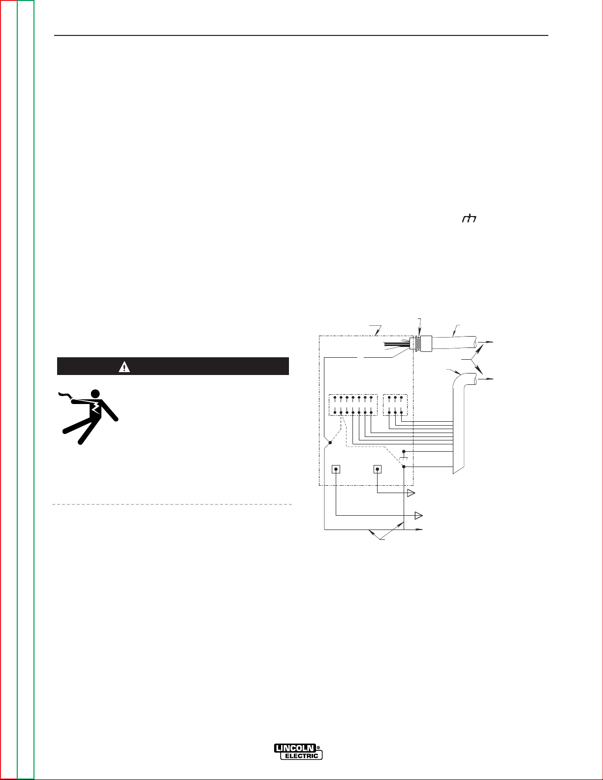
The DC-655 can be used to power any of
the following Lincoln Wire feeders:
SEMI-AUTOMATIC WIRE FEEDERS
• DH-10 • LN-9*
• LN-10 • LN-9 GMA*
• LN-7 GMA* • LN-23P
• LN-742 • LN-25
• LN-7* • LN-8*
AUTOMATIC WIRE FEEDERS*
• NA-3 • NA-5R
• NA-5 • LT-7 Tractor
* European DC-655 models only provide 115VAC for these feeders at the ter-
minal strip (TS2)
CONNECTION OF LINCOLN ELECTRIC
AUTOMATIC OR SEMIAUTOMATIC WIRE
FEEDERS
ELECTRIC SHOCK can kill.
• Only qualified personnel should perform this installation.
• Turn the input power OFF at the dis-
connect switch or fuse box before working on this
equipment.
• Do not touch electrically hot parts.
Auxiliary power for wire feeder operation is available at
both a 14-pin MS receptacle and at terminal strips
with screw-type connections located on the front of
the machine. Refer to the Installation section for
pinouts and lead designations. The two circuits are
isolated, and each is protected by a circuit breaker.
The following descriptions show how to connect the
wire feeders using either the 14-pin MS receptacle or
the terminal strip.
AUTOMATIC WIRE FEEDERS
CONNECTING THE NA-3 OR LT-7 TO THE
IDEALARC DC-655 (TERMINAL STRIP)
1. Set Idealarc DC-655 POWER toggle switch to the
OFF (0) position.
2. Disconnect main AC input power to the Idealarc
DC-655.
3. Connect the wire feeder control cable leads to the
Idealarc DC-655 terminal strip as shown in Figure
C.1.
4. Connect the wire feeder control cable ground lead
to the frame terminal marked .
NOTE: The Idealarc DC-655 must be properly
grounded.
FIGURE C.1 – NA-3 OR LT-7 WIRE FEEDER
CONNECTION TO THE IDEALARC DC-655
5. Extend wire feeder control cable lead #21 so it can
be connected directly to the work piece.
a. Make a bolted connection using AWG #14 or
larger insulated wire. Tape the bolted connection with insulating tape.
b. An S-16586- X remote voltage sensing work
lead is available for this purpose.
c. Keep the #21 lead electrically separate from
the work cable circuit and connection.
d. Tape the #21 lead to work cable for ease of
use.
ACCESSORIES
C-3 C-3
IDEALARC DC-655
Return to Section TOC Return to Section TOC Return to Section TOC Return to Section TOC
Return to Master TOC Return to Master TOC Return to Master TOC Return to Master TOC
WARNING
NEGATIVE
POSITIVE
32
31
2
4
GND
21
ELECTRODE CABLE
TO WORK
POWER SOURCE
CONTROL BOX
21
FOR CONTROL CABLE
WITH 14 PIN MS-TYPE
PLUG CONNECTOR
OR
FOR CONTROL CABLE
WITH TERMINAL STRIP
LEAD CONNECTORS
CONTROL CABLE
14-PIN
RECEPTACLE
75
76
77
TO AUTOMATIC
EQUIPMENT
TO AUTOMATIC
CONTROL CABLE
41
4 2 31
32
75 76
77
21-21
+
REMOTE VOLTAGE SENSING LEAD
Page 26
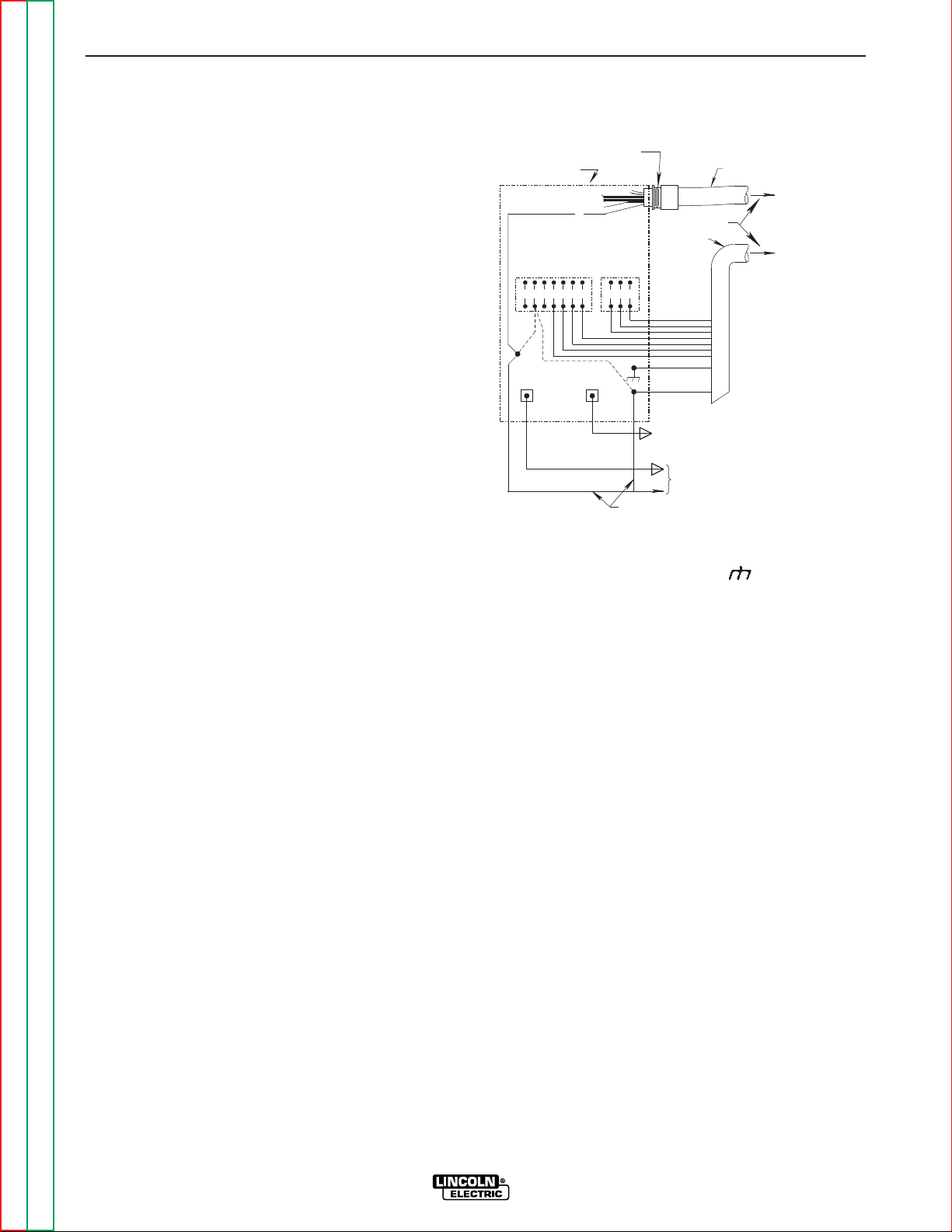
NOTE: The connection diagram shown in Figure C.1
shows the electrode connected for positive
polarity. To change polarity:
a. Set the Idealarc DC-655 POWER toggle
switch to the OFF (0) position.
b. Move the electrode cable to the negative (-)
output terminal. (High inductance or low
inductance, as needed).
c. Move the work cable to the positive (+) output
terminal.
d. If connecting lead #21 to the terminal strip,
connect it to the +21 terminal (to match work
polarity). If work polarity changes back to
negative, lead #21 must be connected to the
-21 terminal.
e. Reverse the leads on the back of the ammeter
and voltmeter in the automatic control box.
f. If the automatic controls include a variable
voltage board, connect its jumper lead to pin
“L”. This will permit the inch down button to
operate. However, the jumper also disables
the cold starting/autostop feature of the automatic controls. Only hot starting will be available.
6. Set the DC-655 OUTPUT CONTROL switch to the
“Remote” position and the OUTPUT TERMINALS
switch in the “Remote” position.
CONNECTING THE NA-5/-5R TO THE
IDEALARC DC-655 (TERMINAL STRIP)
1. Set the Idealarc DC-655 POWER toggle switch to
the OFF (0) position.
2. Disconnect main AC input power to the Idealarc
DC-655.
3. Connect the wire feeder control cable leads to the
Idealarc DC-655 terminal strip as shown in Figure
C.2.
FIGURE C.2 – NA-5/-5R WIRE FEEDER
CONNECTION TO THE IDEALARC DC-655
4. Connect the wire feeder control cable ground lead
to the frame terminal marked .
NOTE: The Idealarc DC-655 must be properly
grounded.
5. Extend wire feeder control cable lead #21 so it can
be connected directly to the work piece.
a. Make a bolted connection using AWG #14 or
larger insulated wire. Tape the bolted connection with insulating tape.
b. An S-16586-X remote voltage sensing work
lead is available for this purpose.
c. Keep the #21 lead electrically separate from
the work cable circuit and connection.
d. Tape the #21 lead to work cable for ease of
use.
ACCESSORIES
C-4 C-4
IDEALARC DC-655
Return to Section TOC Return to Section TOC Return to Section TOC Return to Section TOC
Return to Master TOC Return to Master TOC Return to Master TOC Return to Master TOC
14-PIN
POWER SOURCE
+
21-21
NEGATIVE
41
4 2 31
21
32
POSITIVE
RECEPTACLE
CONTROL CABLE
75 76
77
BOLT TO CABLES FROM NA-5/-5R
WIRE CONTACT AS'BLY
REMOTE VOLTAGE SENSING LEAD
TO NA-5/-5R
INPUT CABLE PLUG
TO WORK
CONTROL CABLE
C
B
A
32
31
2
4
GND
21
FOR CONTROL CABLE
WITH 14 PIN MS-TYPE
PLUG CONNECTOR
OR
FOR CONTROL CABLE
WITH TERMINAL STRIP
LEAD CONNECTORS
Page 27

6. Connect NA-5/-5R wire feeder control jumpers on
Voltage Control Board. See NA-5/-5R Operator’s
Manual.
NOTE: The connection diagram shown in Figure C.2
shows the electrode connected for positive
polarity. To change polarity:
a. Set the Idealarc DC-655 POWER toggle
switch to the OFF (0) position.
b. Move the electrode cable to the negative (-)
output terminal. (High inductance or low
inductance as needed).
c. Move the work cable to the positive (+) output
terminal.
d. If connecting lead #21 to the terminal strip,
connect it to the +21 terminal (to match work
polarity). If work polarity changes back to
negative, lead #21 must be connected to the 21 terminal.
NOTE: For proper NA-5 operation, the electrode
cables must be secured under the clamp bar
on the left side of the NA-5 Control Box.
7. Set the DC-655 OUTPUT CONTROL switch to the
“Remote” position and the OUTPUT TERMINALS
switch to the “Remote” position.
ACCESSORIES
C-5 C-5
IDEALARC DC-655
Return to Section TOC Return to Section TOC Return to Section TOC Return to Section TOC
Return to Master TOC Return to Master TOC Return to Master TOC Return to Master TOC
Page 28
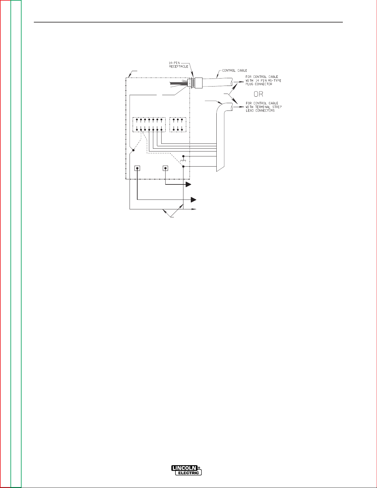
SEMIAUTOMATIC WIRE FEEDERS
CONNECTING THE LN-7 TO THE IDEALARC
DC-655 (14-PIN MS RECEPTACLE)
1. Set the POWER toggle switch to the OFF (0) position.
2. Disconnect main AC input power to the Idealarc
DC-655.
3. Connect the electrode cable from the control
cable to the “+” terminal of the welder and to the
LN-7 wire feeder. Connect the work cable to the
“-” terminal of the welder (High inductance or low
inductance as needed). Reverse this hookup for
negative polarity.
NOTE: Welding cable must be sized for the current
and duty cycle of the application.
4. Connect control cable between the DC-655 and
the LN-7. See Figure C.3.
5. Set the MODE switch to a CV (constant voltage)
position at the welder.
6. Adjust wire feed speed at the LN-7 and set the
welding voltage with the output CONTROL.
NOTE: If optional remote control is used, place the
OUTPUT CONTROL and the OUTPUT TERMINALS switch in the “Remote” position.
ACCESSORIES
C-6 C-6
IDEALARC DC-655
Return to Section TOC Return to Section TOC Return to Section TOC Return to Section TOC
Return to Master TOC Return to Master TOC Return to Master TOC Return to Master TOC
41
4231
32
75 76
77
NEGATIVE
POSITIVE
32
31
2
4
GND
21
ELECTRODE CABLE
TO WIRE FEED UNIT
TO WORK
}
POWER SOURCE
LN-7 TO INPUT
CABLE PLUG
LN-7 CONTROL
CABLE
21
-
21
21
+
REMOTE VOLTAGE SENSING LEAD
FIGURE C.3
IDEALARC DC-655/LN-7 WITH K584 INPUT CABLE ASSEMBLY CONNECTION DIAGRAM
Page 29

CONNECTING THE LN-7 TO THE
IDEALARC DC-655 (TERMINAL STRIP)
1. Set the Idealarc DC-655 POWER toggle switch to
the OFF (0) position.
2. Disconnect main AC input power to the Idealarc
DC 655.
3. Connect the wire feeder control cable leads to the
Idealarc DC-655 terminal strip as shown in Figure
C.3.
4. Connect the wire feeder control cable ground lead
to the frame terminal marked .
NOTE: The Idealarc DC-655 must be properly
grounded.
5. PERFORM THIS STEP ONLY IF THE LN-7 IS
EQUIPPED WITH A METER KIT.
Extend wire feeder control cable lead #21 so it can
be connected directly to the work piece.
a. Make a bolted connection using AWG #14 or
larger insulated wire. Tape the bolted connection with insulating tape.
NOTE: If the work cable length is less than 25 feet
and the connections to the work piece are
secure, then wire feeder control cable lead
#21 can be connected directly to the DC655 terminal strip.
b. An S-16586-X remote voltage sensing work
lead is available for this purpose.
c. Keep the #21 lead electrically separate from
the work cable circuit and connection.
d. Tape the #21 lead to work cable for ease of
use.
NOTE: The connection diagram shown in Figure
C.3 shows the electrode connected for
positive polarity. To change polarity:
a. Set the IDEALARC DC-655 POWER toggle
switch to the OFF (0) position.
b. Move the electrode cable to the negative (-)
output terminal (High inductance or low inductance as needed).
c. Move the work cable to the positive (+) output
terminal.
d. Connect control cable lead #21 to “+21” on
the terminal strip.
ACCESSORIES
C-7 C-7
IDEALARC DC-655
Return to Section TOC Return to Section TOC Return to Section TOC Return to Section TOC
Return to Master TOC Return to Master TOC Return to Master TOC Return to Master TOC
Page 30
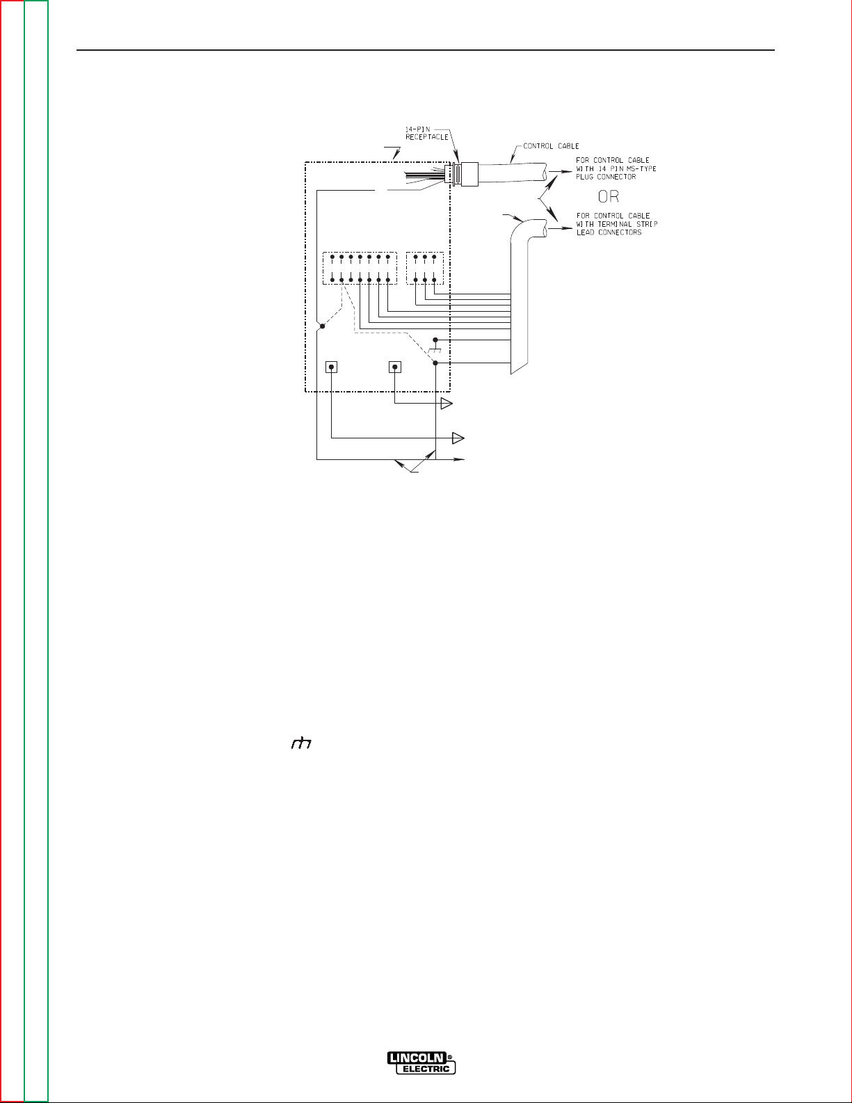
CONNECTING THE LN-8 OR LN-9 TO THE
IDEALARC DC-655 (TERMINAL STRIP)
1. Set the Idealarc DC-655 POWER toggle switch to
the OFF (0) position.
2. Disconnect main AC input power to the Idealarc
DC-655.
3. Connect the wire feeder control cable leads to the
Idealarc DC-655 terminal strip as shown in Figure
C.4.
4. Connect the wire feeder control cable ground lead
to the frame terminal marked .
5. Extend wire feeder control cable lead #21 so it can
be connected directly to the work piece.
a. Make a bolted connection using AWG #14 or
larger insulated wire. Tape the bolted connection with insulating tape.
b. An S-16586- X remote voltage sensing work
lead is available for this purpose.
c. Keep the #21 lead electrically separate from
the work cable circuit and connection.
d. Tape the #21 lead to work cable for ease of
use.
6. Connect LN-9 wire feeder control jumpers on
Voltage Control board. See LN-9 Operator’s
Manual.
NOTE: The connection diagram shown in Figure C.4
shows the electrode connected for positive
polarity. To change polarity:
a. Set the Idealarc DC-655 POWER toggle
switch to the OFF (0) position.
b. Move the electrode cable to the negative (-)
output terminal (High inductance or low
inductance as needed).
c. Move the work cable to the positive (+) output
terminal.
d. Connect control cable lead #21 to “+21” on
the terminal strip.
7. Set the OUTPUT CONTROL switch to the
“Remote” position and the OUTPUT TERMINALS
switch to the “Remote” position.
ACCESSORIES
C-8 C-8
IDEALARC DC-655
Return to Section TOC Return to Section TOC Return to Section TOC Return to Section TOC
Return to Master TOC Return to Master TOC Return to Master TOC Return to Master TOC
FIGURE C.4 - LN-8 OR LN-9 WIRE FEEDER CONNECTION TO THE IDEALARC DC-655
NEGATIVE
POSITIVE
32
31
2
4
GND
21
ELECTRODE CABLE
TO WIRE FEED UNIT
TO WORK
}
POWER SOURCE
N.E.
CABLE
21
A
B
C
}
TO LN-8 OR LN-9
CONTROL
INPUT CABLE PLUG
41
4231
32
75 76
77
21-21
+
REMOTE VOLTAGE SENSING LEAD
Page 31

CONNECTING THE LN-8 OR LN-9 TO THE
IDEALARC DC-655 (14-PIN MS RECEPTACLE)
1. Set the POWER toggle switch to the OFF (0) position.
2. Disconnect main AC input power to the Idealarc
DC-655.
3. Connect the electrode cable from the LN-8 or
LN-9 to the “+” terminal of the welder. Connect
the work cable to the “-” terminal of the welder
(High inductance or low inductance as needed).
Reverse this hookup for negative polarity. See
Figure C.4.
NOTE: Welding cable must be sized for the current
and duty cycle of the application.
4. Connect the control cable between the 14-pin MS
receptacle on the DC-655 and the input cable plug
on the LN-8 or LN-9. See Figure C.4.
5. Set the MODE switch to a CV (constant voltage)
position.
6. Adjust wire feed speed at the LN-8 or LN-9 and
set the welding voltage with the WIRE FEEDER
VOLTAGE CONTROL.
Place the OUTPUT CONTROL switch in the “Remote”
position and the OUTPUT TERMINALS switch in the
“Remote” position.
CONNECTING THE DH-10 TO THE
IDEALARC DC-655 (14-PIN MS RECEPTACLE)
1. Set the POWER toggle switch to the OFF (0) position.
2. Disconnect main AC input power to the Idealarc
DC-655.
3. Connect the electrode cable from the DH-10 to the
“+” terminal of the welder. Connect the work
cable to the “-” terminal of the welder (High inductance or low inductance as needed). Reverse this
hookup for negative polarity.
NOTE: Welding cable must be sized for the current
and duty cycle of the application.
4. Connect the DH-10 input cable between the 14pin MS receptacle on the DC-655 and the input
cable plug on the DH-10. See Figure C.5.
5. Set the MODE switch to a CV (constant voltage)
position.
6. Adjust wire feed speed at the DH-10 and set the
welding voltage with the WIRE FEEDER VOLTAGE
CONTROL.
7. Set the DIP switches on the DH-10 for DC-655.
See the DH-10 Operator’s Manual.
Place the OUTPUT CONTROL switch in the “Remote”
position and the OUTPUT TERMINALS switch in the
“Remote” position.
ACCESSORIES
C-9 C-9
IDEALARC DC-655
Return to Section TOC Return to Section TOC Return to Section TOC Return to Section TOC
Return to Master TOC Return to Master TOC Return to Master TOC Return to Master TOC
FIGURE C.5 – IDEALARC DC-655 DH-10 CONNECTION
ELECTRODE CABLE
-
+
14 PIN
AMPHENOL
POWER SOURCE
TO WORK
DH-10
WIRE
FEEDER
LINCOLN CV-655
DH-10
INPUT CABLE
ASSEMBLY
9 PIN
AMPHENOL
N.E.
Page 32

NOTES
IDEALARC DC-655
Return to Section TOC Return to Section TOC Return to Section TOC Return to Section TOC
Return to Master TOC Return to Master TOC Return to Master TOC Return to Master TOC
Page 33

Return to Master TOC Return to Master TOC Return to Master TOC Return to Master TOC
Section D-1 Section D-1
IDEALARC DC-655
TABLE OF CONTENTS
-MAINTENANCE-
Maintenance .........................................................................................................................Section D
Safety Precautions......................................................................................................................D-2
General Maintenance..................................................................................................................D-2
General Component Locations...................................................................................................D-3
Page 34

SAFETY PRECAUTIONS
ELECTRIC SHOCK can kill.
• Only qualified personnel should perform this maintenance.
• Turn the input power OFF at the disconnect switch
or fuse box before working on this equipment.
• Do not touch electrically hot parts.
GENERAL MAINTENANCE
1. The fan motor has sealed bearings which require
no service.
2. In extremely dusty locations, dirt may restrict the
cooling air causing the welder to run hot with premature tripping of thermal protection. Blow ou;the
welder with low pressure air at regular intervals to
eliminate excessive dirt and dust build-up on internal parts.
3. Periodically check the welding cables. Inspect for
any slits or punctures. Also make sure that all
connections are tight.
MAINTENANCE
D-2 D-2
IDEALARC DC-655
Return to Section TOC Return to Section TOC Return to Section TOC Return to Section TOC
Return to Master TOC Return to Master TOC Return to Master TOC Return to Master TOC
WARNING
Page 35

Return to Section TOC Return to Section TOC Return to Section TOC Return to Section TOC
Return to Master TOC Return to Master TOC Return to Master TOC Return to Master TOC
MAINTENANCE
D-3 D-3
IDEALARC DC-655
DC-655
DC-655
2
15
14
10
8
3
3
4
11
7
1
13
12
9
5
6
FIGURE D.1 - GENERAL COMPONENT LOCATIONS
1. CASE FRONT
2. OUTPUT TERMINALS
3. CASE SIDES
4. CASE TOP
5. RECONNECT PANEL (LOCATION)
6. INPUT CONTACTOR (LOCATION)
7. CONTROL TRANSFORMER (LOCATION)
8. CASE BACK
9. FAN ASSEMBLY
10. CONTROL PANEL
11. PC BOARDS (LOCATION)
12. CHOKE
13. MAIN TRANSFORMER
14. BASE
15. SCR RECTIFIER BRIDGE
Page 36

NOTES
IDEALARC DC-655
Return to Section TOC Return to Section TOC Return to Section TOC Return to Section TOC
Return to Master TOC Return to Master TOC Return to Master TOC Return to Master TOC
Page 37

Return to Master TOC Return to Master TOC Return to Master TOC Return to Master TOC
Section E-1 Section E-1
IDEALARC DC-655
Theory of Operation .............................................................................................................Section E
General Description ....................................................................................................................E-2
Input Line Voltage, Contactor, Reconnect,
Fault Protection, Main and Control Transformers.......................................................................E-2
Control Board, Firing Board, Snubber/Fan
Board and Rectification ..............................................................................................................E-3
Protective Devices and Shutdown Circuits ................................................................................E-4
Thermal Protection ...............................................................................................................E-4
Over Current Protection .......................................................................................................E-4
Peak Current Protection.......................................................................................................E-4
Remote Control Fault Protection..........................................................................................E-4
Shorted Output Rectifier Fault Protection............................................................................E-4
SCR Operation............................................................................................................................E-5
TABLE OF CONTENTS
-THEORY OF OPERATION SECTION-
CONTROL
TRANSFORMER
R
E
C
O
N
N
E
C
T
CONTACTOR
FAULT PROTECTION
115VAC
MAIN
TRANSFORMER
CONTROL
BOARD
SHUNT
OUTPUT
CONTROL
MODE
SWITCH
POSITIVE
TERMINAL
NEGATIVE
TERMINAL
LATCHING
RESISTOR
F
E
E
D
B
A
C
K
F
E
E
D
B
A
C
K
SCR BRIDGE
42VAC
115VAC
42VAC
T
E
R
M
I
N
A
L
S
T
R
I
P
TO OPTIONAL
METER BOARD
HIGH
LOW
ARC FORCE
CONTROL
FIRING
BOARD
SNUBBER
FAN
BOARD
CR2
CONTROL
BOARD
TRANSFORMER
CR1
CHOKE
14-pin
Amphenol
115VAC
Receptacle
Fan
Motor Fan
Thermal
Sensor
42VAC 10VAC
10VAC
32VAC
32VAC
32VAC
SIGNAL
G
A
T
E
S
I
G
N
A
L
GATE
SIGNAL
OUTPUT
CONTROL
FIGURE E.1 – DC-655 BLOCK LOGIC DIAGRAM
Page 38

GENERAL DESCRIPTION
The DC-655 is a three-phase, SCR controlled DC
power source. It is capable of either constant current
or constant voltage output. It is rated at 650 amps,
100% duty cycle with outstanding arc characteristics
for multiple welding processes.
INPUT LINE, CONTACTOR,
RECONNECT, FAULT PROTECTION
AND TRANSFORMERS
The desired three-phase input power is connected to
the DC-655 through an input contactor located in the
input box at the rear of the machine. Two phases of
the input line are also connected to the control transformer. The secondary of the control transformer supplies 115 VAC power to the control board transformer
and to the input contactor through the fault protection
relay. The control board transformer supplies 42 VAC
to the control board.
A reconnect panel allows the user to configure the
machine for the desired input voltage. This threephase AC input is applied to the primary of the main
transformer. The transformer changes the high voltage, low current input power to a lower voltage, higher current output. The finishes or “neutrals” of the
main secondary coils are connected together, and the
six starts of the secondary windings are connected to
the rectifier assembly.
In addition, the main transformer also has eight isolated secondary windings. There are three 32 VAC windings, which provide power and “timing” to the firing
board. The 115 VAC winding powers the fan motor
and provides the user with up to 20 amps of 115 VAC
auxiliary power at the receptacle or 14-pin MS type
connector. The 42 VAC winding provides up to 10
amps at the 14-pin MS type connector. Three other
isolated coils are used to power the optional digital
meter PC board. One winding is rated at 42 VAC, and
the other two are each rated at 10 VAC.
THEORY OF OPERATION
E-2 E-2
IDEALARC DC-655
Return to Section TOC Return to Section TOC Return to Section TOC Return to Section TOC
Return to Master TOC Return to Master TOC Return to Master TOC Return to Master TOC
FIGURE E.2 – INPUT LINE VOLTAGE, CONTACTOR, RECONNECT,
FAULT PROTECTION, MAIN AND CONTROL TRANSFORMERS
NOTE: Unshaded areas of Block Logic Diagram are the subject of discussion.
CONTROL
TRANSFORMER
R
E
C
O
N
N
E
C
T
CONTACTOR
FAULT PROTECTION
115VAC
MAIN
TRANSFORMER
CONTROL
BOARD
SHUNT
OUTPUT
CONTROL
MODE
SWITCH
POSITIVE
TERMINAL
NEGATIVE
TERMINAL
LATCHING
RESISTOR
F
E
E
D
B
A
C
K
F
E
E
D
B
A
C
K
SCR BRIDGE
42VAC
115VAC
42VAC
T
E
R
M
I
N
A
L
S
T
R
I
P
TO OPTIONAL
METER BOARD
HIGH
LOW
ARC FORCE
CONTROL
FIRING
BOARD
SNUBBER
FAN
BOARD
CR2
CONTROL
BOARD
TRANSFORMER
CR1
CHOKE
14-pin
Amphenol
115VAC
Receptacle
Fan
Motor Fan
Thermal
Sensor
42VAC 10VAC
10VAC
32VAC
32VAC
32VAC
SIGNAL
G
A
T
E
S
I
G
N
A
L
GATE
SIGNAL
OUTPUT
CONTROL
Page 39

CONTROL BOARD, FIRING BOARD,
SNUBBER/FAN, BOARD AND
RECTIFICATION
The “neutrals” of the welding secondary windings in
the main transformer are connected together, and the
six starts are connected to the six Silicon Controlled
Rectifier (SCR) assemblies to form a six-phase output.
This six-phase AC output from the main transformer
secondary is rectified and controlled through the SCR
bridge.
A portion of the firing board is a three-phase circuit.
Each phase provides two firing pulses, one for each of
the two SCRs controlled by that phase. When a gate
firing enable signal is received, the firing circuit supplies the proper amount of energy to the gates of the
power SCRs. When this gate firing signal is applied at
the correct time, through the snubber/fan board, the
SCR will turn ON. The amount of ON time versus OFF
time determines the output of the machine. See SCR
Operation. At this time the latching resistor is brought
into the machine’s output circuit. The latching resistor
provides a pre-load for the SCR bridge.
The control board receives current feedback informa-
tion from the shunt and voltage feedback information
from the choke and welding output terminals. This
feedback information is processed on the control
board. The control compares the commands of the
mode switch, the output control potentiometer (or
remote control device) and the arc force control with
the feedback information and sends the appropriate
output control signal to the firing board. In the event
of a “fault condition,” the control board activates the
fault relay (CR2). See Protective Devices and Shut
Down Circuits.
A tapped output choke is connected between the neutral connection of the main transformer secondaries
and the two negative output terminals. This large
inductor stores energy, which provides current filtering
for the welding output of the DC-655. Two negative
output terminals are provided. One is connected to
the tap lead in the choke, thus providing a lower inductance. The other utilizes the entire choke for higher
inductance arc characteristics.
The snubber/fan board furnishes protection to the
SCR bridge from the transient voltages. It also monitors the thermal sensor and activates the fan motor
when cooling is necessary.
THEORY OF OPERATION
E-3 E-3
IDEALARC DC-655
Return to Section TOC Return to Section TOC Return to Section TOC Return to Section TOC
Return to Master TOC Return to Master TOC Return to Master TOC Return to Master TOC
NOTE: Unshaded areas of Block Logic Diagram are the subject of discussion.
FIGURE E.3 – CONTROL BOARD, FIRING BOARD, SNUBBER/FAN BOARD AND RECTIFICATION
CONTROL
TRANSFORMER
115VAC
CONTROL
BOARD
TRANSFORMER
42VAC
CONTACTOR
CR1
CR2
FAULT PROTECTION
OUTPUT
32VAC
32VAC
32VAC
14-pin
115VAC
Amphenol
Receptacle
T
S
E
T
R
115VAC
R
M
I
I
P
N
A
L
42VAC
MAIN
R
E
C
O
N
N
E
C
T
TRANSFORMER
10VAC
42VAC 10VAC
TO OPTIONAL
METER BOARD
FIRING
BOARD
S
G
I
Fan
Motor Fan
A
G
T
N
E
A
L
SNUBBER
FAN
BOARD
SIGNAL
GATE
SCR BRIDGE
CONTROL
Thermal
Sensor
CHOKE
OUTPUT
SIGNAL
LATCHING
RESISTOR
CONTROL
CONTROL
BOARD
F
E
E
D
B
A
C
K
SHUNT
F
E
E
D
B
A
C
K
ARC FORCE
CONTROL
MODE
SWITCH
POSITIVE
TERMINAL
HIGH
NEGATIVE
TERMINAL
LOW
Page 40

THEORY OF OPERATION
E-4 E-4
IDEALARC DC-655
Return to Section TOC Return to Section TOC Return to Section TOC Return to Section TOC
Return to Master TOC Return to Master TOC Return to Master TOC Return to Master TOC
PROTECTIVE DEVICES AND
SHUTDOWN CIRCUITS
THERMAL PROTECTION
Two thermostats protect the DC-655 from excessive
operating temperatures. Excessive operating temperatures may be caused by a lack of cooling air or operating the machine beyond the duty cycle and output
rating. If excessive operating temperatures should
occur, a thermostat will open. This condition will be
indicated by the illumination of the yellow
Thermostatic Protection Light located on the case
front. The fan should continue to run, but the welding
output will be disabled until the machine cools and the
Thermostatic Protection Light is out.
OVER CURRENT PROTECTION
If the average output current exceeds 900 amps for
five to six seconds, the welding output will be disabled. The control board LED 4 shutdown light will
turn on. The higher the current, the quicker the DC655 will shut down. If the average current exceeds
1200 amps, the shutdown will occur in 0.3 seconds.
The over current shutdown circuit can be reset by
opening the feeder gun trigger or switching the DC655 output terminal switch to the OFF position.
PEAK CURRENT PROTECTION
If the peak current exceeds 2500 amps, the welding
output will be disabled and the control board LED 4
shutdown light will turn on. The peak current shutdown circuit can be reset by turning the DC-655 input
switch off.
REMOTE CONTROL FAULT PROTECTION
The remote control leads from the 14-pin receptacles
or terminal strip are protected against voltage faults to
the electrode circuit or auxiliary voltage supplies. If a
fault should occur, the welding output will be disabled
and the control board LED 4 shutdown light will turn
on. This fault protection shutdown circuit can be reset
by opening the feeder gun trigger or switching the DC655 output terminal switch to the OFF position. On
later production machines, LED 3 input shutdown light
will turn on and the input contactor will open.
SHORTED OUTPUT RECTIFIER FAULT
PROTECTION
If a short should occur across one of the SCRs, a
potentially hazardous AC voltage could appear across
the welding output terminals. If such a fault should
occur, the input contactor will open and remove the
input power to the primary of the main transformer.
Also, the control board LED 3 input shutdown light will
turn on. Welding and auxiliary output will not be present, but the pilot light and control board power will be
present until the power switch is turned off.
Page 41

SCR OPERATION
A silicon controlled rectifier (SCR) is a three-terminal
device used to control rather large currents to a load.
An SCR acts very much like a switch. When a gate
signal is applied to the SCR, it is turned ON and there
is current flow from anode to cathode. In the ON state
the SCR acts like a closed switch. When the SCR is
turned OFF, there is no current flow from anode to
cathode. Thus the device acts like an open switch.
As the name suggests, the SCR is a rectifier, so it
passes current only during positive half cycles of the
AC supply. The positive half cycle is the portion of the
sine wave in which the anode of the SCR is more positive than the cathode.
When an AC supply voltage is applied to the SCR, the
device spends a certain portion of the AC cycle time
in the ON state and the remainder of the time in the
OFF state. The amount of time spent in the ON state
is controlled by the Gate.
An SCR is fired by a short burst of current into the
gate. This gate pulse must be more positive than the
cathode voltage. Since there is a standard PN junction between gate and cathode, the voltage between
these terminals must be slightly greater than 0.6V .
Once the SCR has fired, it is not necessary to continue the flow of gate current. As long as current continues to flow from anode to cathode, the SCR will
remain on. When the anode to cathode current drops
below a minimum value, called holding current, the
SCR will shut off. This normally occurs as the AC supply voltage passes through zero into the negative portion of the sine wave. If the SCR is turned on early in
the positive half cycle, the conduction time is longer,
resulting in greater SCR output. If the gate firing
occurs later in the cycle, the conduction time is less,
resulting in lower SCR output.
THEORY OF OPERATION
E-5 E-5
IDEALARC DC-655
Return to Section TOC Return to Section TOC Return to Section TOC Return to Section TOC
Return to Master TOC Return to Master TOC Return to Master TOC Return to Master TOC
FIGURE E.4 – SCR OPERATION
Page 42

NOTES
IDEALARC DC-655
Return to Section TOC Return to Section TOC Return to Section TOC Return to Section TOC
Return to Master TOC Return to Master TOC Return to Master TOC Return to Master TOC
Page 43

Return to Master TOC Return to Master TOC Return to Master TOC Return to Master TOC
Section F-1 Section F-1
IDEALARC DC-655
Troubleshooting & Repair Section.................................................................................Section F
How to Use Troubleshooting Guide ......................................................................................F-2
PC Board Troubleshooting Procedures.................................................................................F-3
Troubleshooting Guide .................................................................................................F-4–F-12
Test Procedures
Internal Trigger Circuit Test ...........................................................................................F-13
Firing Board Test ...........................................................................................................F-17
Main Transformer (T1) Voltage Test...............................................................................F-22
Control Transformer (T2) Voltage Test ...........................................................................F-27
Control Board Transformer (T3) Test.............................................................................F-30
Input Contactor Test......................................................................................................F-32
Static SCR Test .............................................................................................................F-35
Active SCR Test.............................................................................................................F-38
Thermal Fan/Snubber Board LED Chart.......................................................................F-41
Control Board LED Chart ..............................................................................................F-42
Oscilloscope Waveforms
Normal Open Circuit Voltage Waveform-Constant Current Mode................................F-43
Normal Open Circuit Voltage Waveform-Constant Voltage MIG Maximum Output.....F-44
Normal Open Circuit Voltage Waveform-Constant Voltage MIG Minimum Output......F-45
Typical Output Voltage Waveform-Constant Voltage MIG............................................F-46
Typical SCR Gate Voltage Waveform-Constant Voltage MIG.......................................F-47
Abnormal Open Circuit Voltage Waveform-Constant Voltage MIG ..............................F-48
Replacement Procedures
Input Contactor (CR1) Cleaning/Replacement .............................................................F-49
SCR Rectifier Bridge Removal and Replacement ........................................................F-51
Main Transformer and Choke Removal and Replacement ...........................................F-54
Retest After Repair ..............................................................................................................F-57
TABLE OF CONTENTS
TROUBLESHOOTING & REPAIR SECTION
Page 44

Return to Section TOC Return to Section TOC Return to Section TOC Return to Section TOC
Return to Master TOC Return to Master TOC Return to Master TOC Return to Master TOC
HOW TO USE TROUBLESHOOTING GUIDE
Service and repair should be performed by only Lincoln Electric Factory Trained Personnel.
Unauthorized repairs performed on this equipment may result in danger to the technician and machine
operator and will invalidate your factory warranty. For your safety and to avoid Electrical Shock, please
observe all safety notes and precautions detailed throughout this manual.
TROUBLESHOOTING & REPAIR
F-2 F-2
IDEALARC DC-655
CAUTION
This Troubleshooting Guide is provided to help
you locate and repair possible machine malfunctions. Simply follow the three-step procedure
listed below.
Step 1. LOCATE PROBLEM (SYMPTOM). Look
under the column labeled “PROBLEM (SYMPTOMS). This column describes possible symptoms that the machine may exhibit. Find the listing that best describes the symptom that the
machine is exhibiting. Symptoms are grouped
into three main categories: Output Problems,
Function Problems and Welding Problems.
Step 2. PERFORM EXTERNAL TESTS. The
second column, labeled “POSSIBLE AREAS OF
MISADJUSTMENT(S)”, lists the obvious external
possibilities that may contribute to the machine
symptom. Perform these tests/checks in the
order listed. In general, these tests can be conducted without removing the case wrap-around
cover.
Step 3. PERFORM COMPONENT TESTS. The
last column, labeled “Recommended Course of
Action” lists the most likely components that may
have failed in your machine. It also specifies the
appropriate test procedure to verify that the subject component is either good or bad. If there are
a number of possible components, check the
components in the order listed to eliminate one
possibility at a time until you locate the cause of
your problem.
All of the referenced test procedures referred to in
the Troubleshooting Guide are described in detail
at the end of this chapter. Refer to the
Troubleshooting and Repair Table of Contents to
locate each specific Test Procedure. All of the
referred to test points, components, terminal
strips, etc., can be found on the referenced electrical wiring diagrams and schematics. Refer to
the Electrical Diagrams Section Table of Contents
to locate the appropriate diagram.
WARNING
If for any reason you do not understand the test procedures or are unable to perform the test/repairs
safely, contact the Lincoln Electric Service Department for electrical troubleshooting assistance before
you proceed. Call 1-800-833-9353.
Page 45

TROUBLESHOOTING & REPAIR
F-3 F-3
IDEALARC DC-655
Return to Section TOC Return to Section TOC Return to Section TOC Return to Section TOC
Return to Master TOC Return to Master TOC Return to Master TOC Return to Master TOC
Sometimes machine failures appear to be due to PC
board failures. These problems can sometimes be
traced to poor electrical connections. To avoid problems when troubleshooting and replacing PC boards,
please use the following procedure:
1. Determine to the best of your technical ability
that the PC board is the most likely component
causing the failure symptom.
2. Check for loose connections at the PC board to
assure that the PC board is properly connected.
3. If the problem persists, replace the suspect PC
board using standard practices to avoid static
electrical damage and electrical shock. Read
the warning inside the static resistant bag and
perform the following procedures:
PC board can be damaged by static electricity.
- Remove your body’s static
charge before opening the staticshielding bag. Wear an anti-static
wrist strap. For safety, use a 1
Meg ohm resistive cord connected
to a grounded part of the
equipment frame.
- If you don’t have a wrist strap,
touch an un-painted, grounded,
part of the equipment frame. Keep
touching the frame to prevent
static build-up. Be sure not to
touch any electrically live parts at
the same time.
- Tools which come in contact with the PC board must
be either conductive, anti-static or static-dissipative.
ELECTRIC SHOCK
can kill.
•
Have an electrician install and
service this equipment. Turn the
input power OFF at the fuse box
before working on equipment. Do
not touch electrically hot parts.
- Remove the PC board from the static-shielding bag
and place it directly into the equipment. Don’t set the
PC board on or near paper, plastic or cloth which
could have a static charge. If the PC board can’t be
installed immediately, put it back in the static-shielding bag.
- If the PC board uses protective shorting jumpers,
don’t remove them until installation is complete.
- If you return a PC board to The Lincoln Electric
Company for credit, it must be in the static-shielding
bag. This will prevent further damage and allow proper failure analysis.
4. Test the machine to determine if the failure
symptom has been corrected by the
replacement PC board.
NOTE: It is desirable to have a spare (known good)
PC board available for PC board troubleshooting.
NOTE
: Allow the machine to heat up so that all
electrical components can reach their operating
temperature.
5. Remove the replacement PC board and
substitute it with the original PC board to
recreate the original problem.
a. If the original problem does not reappear by
substituting the original board, then the PC
board was not the problem. Continue to look
for bad connections in the control wiring
harness, junction blocks, and terminal strips.
b. If the original problem is recreated by the
substitution of the original board, then the PC
board was the problem. Reinstall the
replacement PC board and test the machine.
6. Always indicate that this procedure was
followed when warranty reports are to be
submitted.
NOTE
: Following this procedure and writing on the
warranty report, “INSTALLED AND SWITCHED PC
BOARDS TO VERIFY PROBLEM,” will help avoid
denial of legitimate PC board warranty claims.
PC BOARD TROUBLESHOOTING PROCEDURES
ATTENTION
Static-Sensitive
Devices
Handle only at
Static-Safe
Workstations
WARNING
CAUTION
Page 46

Return to Section TOC Return to Section TOC Return to Section TOC Return to Section TOC
Return to Master TOC Return to Master TOC Return to Master TOC Return to Master TOC
TROUBLESHOOTING & REPAIR
F-4 F-4
IDEALARC DC-655
Observe Safety Guidelines TROUBLESHOOTING GUIDE
detailed in the beginning of this manual.
CAUTION
If for any reason you do not understand the test procedures or are unable to perform the test/repairs safely, contact the Lincoln Electric Service Department for electrical troubleshooting assistance before you proceed. Call
1-800-833-9353.
PROBLEMS
(SYMPTOMS)
POSSIBLE AREAS OF
MISADJUSTMENT(S)
RECOMMENDED
COURSE OF ACTION
OUTPUT PROBLEMS
Major physical or electrical damage is evident.
1. Contact the Lincoln Electric
Service Dept. 1-800-833-9353.
The machine is dead - the input contactor does not operate. The pilot light is not lit.
1. The power switch (S1) is in the
ON position.
2. Check for blown or missing
fuses in the input lines.
3. Check the three-phase input
line voltage at the machine.
The input voltage must match
the rating plate and reconnect
panel.
1. Check the power switch (S1)
and associated leads and connections. See the Wiring
Diagram.
2. Perform the Control Transformer Test.
The input contactor operates, but no welding output. The 115 VAC auxiliary supply is present at the receptacle.
1. Check the electrode and work
cables for loose or faulty connections.
2. If the Thermal Protection Light
is ON, the machine is overheated. Wait for the machine to
cool and remedy the cause of
the overheating problem. See
the Fan/Snubber Board LED
Chart.
3. Make certain either the output
terminals switch is in the ON
position or the external gun
trigger circuit is functioning
properly.
1. Perform the Internal Trigger
Circuit Test.
2. Perform the Firing Board Test.
3. Perform the Main Transformer
Test.
4. Perform the SCR Output
Bridge Test.
5. The control board may be
faulty. See Control Board LED
Chart.
Page 47

Return to Section TOC Return to Section TOC Return to Section TOC Return to Section TOC
Return to Master TOC Return to Master TOC Return to Master TOC Return to Master TOC
TROUBLESHOOTING & REPAIR
F-5 F-5
IDEALARC DC-655
Observe Safety Guidelines
TROUBLESHOOTING GUIDE
detailed in the beginning of this manual.
CAUTION
If for any reason you do not understand the test procedures or are unable to perform the test/repairs safely, contact the Lincoln Electric Service Department for electrical troubleshooting assistance before you proceed. Call
1-800-833-9353.
PROBLEMS
(SYMPTOMS)
POSSIBLE AREAS OF
MISADJUSTMENT(S)
RECOMMENDED
COURSE OF ACTION
OUTPUT PROBLEMS
The input contactor chatters. 1. Check the three-phase input
line voltage at the machine.
The input voltage must match
the rating plate and reconnect
panel configuration.
1. Check for loose or faulty wiring
between the input power
switch (SW1), the fault protection relay (CR2) and the input
contactor. See the Wiring
Diagram.
2. The fault protection relay (CR2)
may have defective contacts.
Check or replace.
3. The control board may be
defective. See the Control
Board LED Chart.
4. The input contactor may be
faulty.
The machine is dead - the input contactor does not operate. The pilot light is lit.
1. Check the three-phase input
line voltage at the machine.
The input voltage must match
the rating plate and reconnect
panel configuration.
2. Turn the machine off and then
back on to reset the fault protection circuit. See the Control
Board LED Chart.
1. Check the wiring between the
fault protection relay (CR2) and
the input contactor (CR1).
2. The fault protection relay (CR2)
may have defective contacts.
Check or replace.
3. The input contactor may be
faulty.
Page 48

Return to Section TOC Return to Section TOC Return to Section TOC Return to Section TOC
Return to Master TOC Return to Master TOC Return to Master TOC Return to Master TOC
TROUBLESHOOTING & REPAIR
F-6 F-6
IDEALARC DC-655
TROUBLESHOOTING GUIDE Observe Safety Guidelines
detailed in the beginning of this manual.
CAUTION
If for any reason you do not understand the test procedures or are unable to perform the test/repairs safely, contact the Lincoln Electric Service Department for electrical troubleshooting assistance before you proceed. Call
1-800-833-9353.
PROBLEMS
(SYMPTOMS)
POSSIBLE AREAS OF
MISADJUSTMENT(S)
RECOMMENDED
COURSE OF ACTION
OUTPUT PROBLEMS
The machine has welding output but no control.
1. Check the output control switch
(SW3) for proper setting.
2. If a remote control cable is
used, make certain the cable
and connections are good.
1. The output control potentiometer, output control switch (SW3)
or associated wiring may be
defective. See the Wiring
Diagram.
2. Perform the Firing Board Test.
3. Perform the SCR Output
Bridge Test.
4. The control board may be
faulty. See the Control Board
LED Chart.
The machine does not have maximum output.
1. Check the three-phase input
lines at the DC-655. Make certain the input voltages match
the machine’s rating and reconnect panel configuration.
2. Put the output control switch
(SW3) in the “Local” control
position. If the problem is
resolved, the remote unit or
wire feeder may be defective.
1. The output control potentiometer, output control switch (SW3)
or associated wiring may be
defective. See the Wiring
Diagram.
2. Perform the Main Transformer
Test.
3. Perform the Firing Board Test.
4. Perform the SCR Bridge Test.
5. The control board may be
faulty. See the Control Board
LED Chart.
Page 49

Return to Section TOC Return to Section TOC Return to Section TOC Return to Section TOC
Return to Master TOC Return to Master TOC Return to Master TOC Return to Master TOC
TROUBLESHOOTING & REPAIR
F-7 F-7
IDEALARC DC-655
Observe Safety Guidelines
TROUBLESHOOTING GUIDE
detailed in the beginning of this manual.
CAUTION
If for any reason you do not understand the test procedures or are unable to perform the test/repairs safely, contact the Lincoln Electric Service Department for electrical troubleshooting assistance before you proceed. Call
1-800-833-9353.
PROBLEMS
(SYMPTOMS)
POSSIBLE AREAS OF
MISADJUSTMENT(S)
RECOMMENDED
COURSE OF ACTION
OUTPUT PROBLEMS
The 115 VAC receptacle is not working. The machine’s welding output is normal.
1. The circuit breaker may be
tripped. Reset if necessary.
2. Make sure the 115 VAC plug
and “load” is in good working
condition.
1. The circuit breaker may be
defective. Check associated
wiring. See the Wiring Diagram.
2. Check for 115 VAC at terminals
#31 and #32 on the terminal
strip. If 115 VAC is present at
the terminal strip, check the
wiring between the terminal
stirp, the circuit breaker and the
115 VAC receptacle. If 115 VAC
is NOT present at the terminal
strip, perform the Main
Transformer Test.
3. The 115 VAC receptacle may
be defective.
When not welding for a period of time, the machine shuts down.
1. This may be a normal condition.
See the Idle Shut Down Timer.
Page 50

Return to Section TOC Return to Section TOC Return to Section TOC Return to Section TOC
Return to Master TOC Return to Master TOC Return to Master TOC Return to Master TOC
TROUBLESHOOTING & REPAIR
F-8 F-8
IDEALARC DC-655
Observe Safety Guidelines
TROUBLESHOOTING GUIDE
detailed in the beginning of this manual.
CAUTION
If for any reason you do not understand the test procedures or are unable to perform the test/repairs safely, contact the Lincoln Electric Service Department for electrical troubleshooting assistance before you proceed. Call
1-800-833-9353.
PROBLEMS
(SYMPTOMS)
POSSIBLE AREAS OF
MISADJUSTMENT(S)
RECOMMENDED
COURSE OF ACTION
FUNCTION PROBLEMS
The output control potentiometer
does not function when the output
control switch (SW3) is in the
“Local” position. The DC-655
operates normally when controlled
remotely.
1. The output control switch (SW3)
may be defective.
1. The output control potentiometer or associated wiring may be
faulty. See the Wiring Diagram.
The remote output control unit
does not function properly when
the output control switch (SW3) is
in the “Remote” position. The DC655 operates normally when controlled locally from the machine’s
output control potentiometer.
1. The remote control unit or connecting cable may be defective.
Check or replace.
1. The output control switch (SW3)
may be defective. Check or
replace. See the Wiring
Diagram.
2. Check the remote control leads
#75, #76 and #77 at plug P15,
the terminal strip and the 14-pin
MS type connector. Check for
loose or faulty connections.
See the Wiring Diagram.
Page 51

TROUBLESHOOTING & REPAIR
F-9 F-9
IDEALARC DC-655
Return to Section TOC Return to Section TOC Return to Section TOC Return to Section TOC
Return to Master TOC Return to Master TOC Return to Master TOC Return to Master TOC
Observe Safety Guidelines TROUBLESHOOTING GUIDE
detailed in the beginning of this manual.
CAUTION
If for any reason you do not understand the test procedures or are unable to perform the test/repairs safely, contact the Lincoln Electric Service Department for electrical troubleshooting assistance before you proceed. Call
1-800-833-9353.
PROBLEMS
(SYMPTOMS)
POSSIBLE AREAS OF
MISADJUSTMENT(S)
RECOMMENDED
COURSE OF ACTION
FUNCTION PROBLEMS
The Thermal Protection Light is on but the fan does not run.
1. Check for obstructions that
could prevent the fan from turning.
1. The fan motor could be faulty.
Check or replace.
2. The Thermal Fan/Snubber PC
Board may be defective. See
the Thermal Fan/Snubber PC
Board LED Chart.
The fan runs continuously. 1. Note: The fan is thermal con-
trolled. Under normal conditions, it does not continuously
run.
1. The Thermal Fan Thermistor
may be faulty. See the Wiring
Diagram.
2. The Thermal Fan/Snubber PC
Board may be defective. See
the Thermal Fan/Snubber PC
Board LED Chart.
One or both of the optional digital meters are not lit.
1. Check for loose plugs P13 and
P12 at the digital meter PC
board.
1. The digital meter board may not
be receiving voltages from the
T1 transformer windings.
Perform the Main Transformer
Test.
2. Check the wiring between Plug
J13 and the associated leads at
the main transformer. See the
Wiring Diagram.
3. The digital meter PC board may
be faulty.
Page 52

TROUBLESHOOTING & REPAIR
F-10 F-10
IDEALARC DC-655
Return to Section TOC Return to Section TOC Return to Section TOC Return to Section TOC
Return to Master TOC Return to Master TOC Return to Master TOC Return to Master TOC
Observe Safety Guidelines TROUBLESHOOTING GUIDE
detailed in the beginning of this manual.
CAUTION
If for any reason you do not understand the test procedures or are unable to perform the test/repairs safely, contact the Lincoln Electric Service Department for electrical troubleshooting assistance before you proceed. Call
1-800-833-9353.
PROBLEMS
(SYMPTOMS)
POSSIBLE AREAS OF
MISADJUSTMENT(S)
RECOMMENDED
COURSE OF ACTION
FUNCTION PROBLEMS
The optional digital meter is not
working properly and/or the display is erratic.
1. Make certain plugs P12 and
P13 are securely plugged into
the digital meter PC board.
Also make sure plug P3 is
securely plugged into the control board.
1. Check feedback leads #222,
#210, #201 and #202 for loose
or faulty connections. See the
Wiring Diagram.
2. The optional digital meter PC
board may be faulty.
The analog meters are not reading correctly.
1. Make sure plug P3 is securely
plugged into the control board
and plug J14 is securely seated
in the plug assembly from the
control board.
1. Check feedback leads #222,
#210, #201 and #202 for loose
or faulty connections. See the
Wiring Diagram.
2. The meter(s) may be defective.
Page 53

TROUBLESHOOTING & REPAIR
F-11 F-11
IDEALARC DC-655
Return to Section TOC Return to Section TOC Return to Section TOC Return to Section TOC
Return to Master TOC Return to Master TOC Return to Master TOC Return to Master TOC
Observe Safety Guidelines TROUBLESHOOTING GUIDE
detailed in the beginning of this manual.
CAUTION
If for any reason you do not understand the test procedures or are unable to perform the test/repairs safely, contact the Lincoln Electric Service Department for electrical troubleshooting assistance before you proceed. Call
1-800-833-9353.
PROBLEMS
(SYMPTOMS)
POSSIBLE AREAS OF
MISADJUSTMENT(S)
RECOMMENDED
COURSE OF ACTION
WELDING PROBLEMS
Poor arc characteristics in all processes.
1. Check the three-phase input
line voltage at the machine.
The input voltage must match
the rating plate and reconnect
panel.
2. Check the welding cables for
loose or faulty connections.
3. Make sure the proper welding
procedures are being used.
(Wire feed speed, arc voltage
and wire size)
4. Make sure the negative welding
cable is connected to the correct negative output terminal.
(Low or High inductance)
1. Check the weld mode switch
(SW2) and associated leads for
proper operation or loose or
faulty connections. See the
Wiring Diagram.
2. Perform the Firing Board Test.
3. Perform the SCR Bridge Test.
4. Perform the Main Transformer
Test.
5. The control board may be
faulty. See the Control Board
LED Chart.
Poor arc striking with semiautomatic or automatic wire feeders.
1. Make sure the proper welding
procedures are being used.
(Wire feed speed, arc voltage
and wire size)
2. Check the welding cables for
loose or faulty connections.
1. Perform the Firing Board Test.
2. Perform the SCR Bridge Test.
3. The control board may be
faulty. See the Control Board
LED Chart.
Page 54

TROUBLESHOOTING & REPAIR
F-12 F-12
IDEALARC DC-655
Return to Section TOC Return to Section TOC Return to Section TOC Return to Section TOC
Return to Master TOC Return to Master TOC Return to Master TOC Return to Master TOC
Observe Safety Guidelines TROUBLESHOOTING GUIDE
detailed in the beginning of this manual.
CAUTION
If for any reason you do not understand the test procedures or are unable to perform the test/repairs safely, contact the Lincoln Electric Service Department for electrical troubleshooting assistance before you proceed. Call
1-800-833-9353.
PROBLEMS
(SYMPTOMS)
POSSIBLE AREAS OF
MISADJUSTMENT(S)
RECOMMENDED
COURSE OF ACTION
WELDING PROBLEMS
The arc is variable or sluggish. 1. Check the three-phase input
line voltage at the machine.
The input voltage must match
the rating plate and reconnect
panel configuration.
2. Make sure the machine’s settings are correct for the welding
process.
3. Check the welding cables for
loose or faulty connections.
Also make sure cables are sized
correctly for the welding current.
4. See CV Mode Current
Limiting.
1. Check the weld mode switch
(SW2) and associated leads for
proper operation or loose or
faulty connections. See the
Wiring Diagram.
2. Perform the Firing Board Test.
3. Perform the SCR Bridge Test.
4. Perform the Main Transformer
Test.
5. The control board may be
faulty. See the Control Board
LED Chart.
The Arc Force Control (R4) has no effect on the arc.
1. The Arc Force Control is active
only in the CC Stick mode.
2. The effect of the Arc Force
Control will be less noticeable
at high welding currents. Weld
at low currents (less than 150
amps) and check the Arc Force
control function.
1. Check the Arc Force Control
potentiometer (R4) for the correct resistance and proper
operation. Normal resistance is
10,000 ohms.
2. Check the continuity of leads
#321, #322 and #328 from the
Arc Force Control to the control
board. See the Wiring Diagram.
3. The control board may be
faulty. Replace.
Page 55

Return to Section TOC Return to Section TOC Return to Section TOC Return to Section TOC
Return to Master TOC Return to Master TOC Return to Master TOC Return to Master TOC
TROUBLESHOOTING & REPAIR
F-13 F-13
IDEALARC DC-655
INTERNAL TRIGGER CIRCUIT TEST
WARNING
Service and repair should be performed by only Lincoln Electric factory trained personnel. Unauthorized repairs performed on this equipment may result in danger to the technician or machine operator and will invalidate your factory warranty. For your safety and
to avoid electrical shock, please observe all safety notes and precautions detailed
throughout this manual.
If for any reason you do not understand the test procedures or are unable to perform the
test/repairs safely, contact the Lincoln Electric Service Department for electrical troubleshooting assistance before you proceed. Call 216-383-2531 or 1-800-833-9353
(WELD).
TEST DESCRIPTION
This test will help determine if the wiring and connections are good from the 14-pin
receptacle and terminal strip through the P15 and P16 connectors and thermostats to the
firing board. The technician will also be able to determine if the 42 VAC trigger supply
voltage is present.
MATERIALS NEEDED
Ohmmeter (Multimeter)
DC-655 Wiring Diagram
Simplified Trigger Diagram
Page 56

Return to Section TOC Return to Section TOC Return to Section TOC Return to Section TOC
Return to Master TOC Return to Master TOC Return to Master TOC Return to Master TOC
TROUBLESHOOTING & REPAIR
F-14 F-14
IDEALARC DC-655
ELECTRIC SHOCK can kill.
• Do not touch electrically hot
parts.
TEST PROCEDURE
1. With the correct input power applied to the
DC-655 and the trigger circuit activated,
LED 10 on the firing board should be lit.
See Figure F.1. If LED 10 lights when the
trigger is activated, the wiring and circuitry
to the firing board is good. Perform the
Firing Board Test and see the Control
Board LED Chart. See the Simplified
Trigger Diagram.
NOTE: LED 10 should not be lit if the trigger
circuit is not activated.
2. If LED 10 does not light when the trigger circuit is activated, proceed with the following
voltage and continuity checks.
3. Check the 10 Amp circuit breaker. It is the
one closest to the 115V duplex receptacle.
Reset if tripped.
WARNING
FIGURE F.1 – FIRING BOARD TRIGGER CIRCUIT TEST POINTS AND LEDS
INTERNAL TRIGGER CIRCUIT TEST (continued)
8
7
6
5
4
3
2
1
16
15
14
13
12
11
10
9
LED7 LED8 LED9
LED1
LED3
LED5
LED2
LED4
LED6
G2699-[ ]
LED10
FIRING BOARD
J5
J6
J7
J4
Page 57

4. Check for the presence of 42 VAC at the terminal strip ( #2 to #41). See the Simplified
Trigger Diagram.
5. If 42 VAC is not present at the terminal strip,
check the circuit breaker and leads #42A
and #41 at the P15 connector. See the
Simplified Trigger Diagram. Also perform
the Main Transformer Test.
6. Remove the main input supply power to the
DC-655 machine.
7. Check continuity (zero ohms) from lead
#42A ( plug P15 pin-13) to lead #2 at the 14pin receptacle pin “C”. Also check continuity to the output terminal switch. See the
Simplified Trigger Diagram. If a resistance
of any value is indicated, check the associated wires and plugs.
8. Check continuity (zero ohms) from pin “D”
(lead #4) at the 14-pin receptacle to the output terminal switch and also to plug J5-pin
9 at the firing board. See the Simplified
Trigger Diagram and Figures F. 1 and F.2. If
a resistance of any value is indicated, check
the associated wires and plugs.
TROUBLESHOOTING & REPAIR
F-15 F-15
IDEALARC DC-655
Return to Section TOC Return to Section TOC Return to Section TOC Return to Section TOC
Return to Master TOC Return to Master TOC Return to Master TOC Return to Master TOC
FIGURE F.2 – TERMINAL STRIP AND 14-PIN RECEPTACLE
POSITIVE
OUTPUT
TERMINAL
TERMINAL STRIP
COVER PANEL
14 PIN MS RECEPTACLE
LOW INDUCTANCE
NEGATIVE OUTPUT
TERMINAL
C=2
HIGH INDUCTANCE
NEGATIVE OUTPUT
TERMINAL
B=GND
L
D=4
E=77
A=32
K=42
J=31
I=41
N
H=21
G=75
F=76
M
-21 41 4 2 31 32 75 76
+21
TERMINAL STRIP
77
Page 58

9. Check continuity (zero ohms) from lead #41
(plug P15 pin-10) to plug J5-pin 1 at the firing board. See the Simplified Trigger
Diagram and Figure F.1. If a resistance of
any value is indicated, check the associated wires, plugs and thermostats.
TROUBLESHOOTING & REPAIR
F-16 F-16
IDEALARC DC-655
Return to Section TOC Return to Section TOC Return to Section TOC Return to Section TOC
Return to Master TOC Return to Master TOC Return to Master TOC Return to Master TOC
FIGURE F.3 – SIMPLIFIED TRIGGER DIAGRAM
10AMP
CIRCUIT
BREAKER
42A
TO #42 AT MAIN
TRANSFORMER
FIRING BOARD
14-PIN
RECEPTACLE
C
D
TERMINAL
P16
2
5
6
4
STRIP
2
4
41
P15
13
5
9
11
10
2
#
#4
#41
TO #41 AT MAIN
TRANSFORMER
OUTPUT
TERMINAL
SWITCH
N.C.
SECONDARY
THERMOSTAT
11J5
#309
TO
CONTROL
10J5
BOARD
#310
LED10
#4
#273
N.C.
CHOKE LEAD
THERMOSTAT
#41
9J5
1J5
LATCHING
RESISTOR
ENABLE
FIRING
CIRCUIT
ENABLE
Page 59

Return to Section TOC Return to Section TOC Return to Section TOC Return to Section TOC
Return to Master TOC Return to Master TOC Return to Master TOC Return to Master TOC
TROUBLESHOOTING & REPAIR
F-17 F-17
IDEALARC DC-655
FIRING BOARD TEST
WARNING
Service and repair should be performed by only Lincoln Electric factory trained personnel. Unauthorized repairs performed on this equipment may result in danger to the technician or machine operator and will invalidate your factory warranty. For your safety and
to avoid electrical shock, please observe all safety notes and precautions detailed
throughout this manual.
If for any reason you do not understand the test procedures or are unable to perform the
test/repairs safely, contact the Lincoln Electric Service Department for electrical troubleshooting assistance before you proceed. Call 216-383-2531 or 1-800-833-9353
(WELD).
TEST DESCRIPTION
This test will help determine whether or not the firing board is receiving the correct voltages and signals. The LEDs (Light Emitting Diodes) will help determine if the firing board
is generating gate signals for the main SCRs.
MATERIALS NEEDED
Volt/ohmmeter (Multimeter)
DC-655 wiring diagram and firing board schematic drawing
Page 60

Return to Section TOC Return to Section TOC Return to Section TOC Return to Section TOC
Return to Master TOC Return to Master TOC Return to Master TOC Return to Master TOC
TROUBLESHOOTING & REPAIR
F-18 F-18
IDEALARC DC-655
FIRING BOARD TEST (continued)
FIGURE F.4 – FIRING BOARD TRIGGER CIRCUIT TEST POINTS AND LEDs
TEST PROCEDURE
1. Disconnect the AC input power to the DC655 machine.
2. Locate the firing board on the left side of
the control box.
3. Perform a visual inspection on the firing
board to see if there are any loose or faulty
connections or physical damage.
4. Connect the correct AC input power to the
DC-655.
ELECTRIC SHOCK can kill.
• Do not touch electrically hot
parts.
5. Turn the power switch (SW1) to the ON
position.
6. LEDs 7, 8 and 9 should be lit and equally
bright. See Figure F.4 to locate the LEDs.
Use Table F.1 to check operation of LEDs 7,
8, and 9. The three LEDs should be of
equal intensity.
WARNING
LED7 LED8 LED9
LED1
LED3
LED5
LED2
LED4
LED6
G2699-[ ]
LED10
FIRING BOARD
(205) 8
(206) 7
(207) 6
(208) 5
J5
4
3
2
1
16 (204)
15 (203)
14
13 (231)
12 (215)
11
10
9
J6
J7
J4
Page 61

Return to Section TOC Return to Section TOC Return to Section TOC Return to Section TOC
Return to Master TOC Return to Master TOC Return to Master TOC Return to Master TOC
TROUBLESHOOTING & REPAIR
F-19 F-19
IDEALARC DC-655
FIRING BOARD TEST (continued)
IF THEN
LED 7 is ON 32 VAC power is being supplied to the
firing board from leads #203 and
#204 connected to the phase angle
winding in the Main Transformer.
Normal is 32 VAC.
LED 7 is not lit or is dimmer than The proper AC voltage may not be
the other LEDs reaching the firing board. Check for
loose or faulty connections. Perform
the Main Transformer Test.
LED 8 is ON 32 VAC power is being supplied to the
firing board from leads #205 and #206
connected to the phase angle winding in
the Main Transformer.
LED 8 is not lit or is dimmer than The proper AC power may not be
the other LEDs reaching the firing board. Check for
loose or faulty connections. Perform
the Main Transformer Test.
LED 9 is ON 32 VAC power is being supplied to
the firing board from leads #207 and
#208 connected to the phase angle
winding in the Main Transformer.
LED 9 is not lit or is dimmer than The proper AC power may not be
the other LEDs reaching the firing board. Check for
loose or faulty connections. Perform
the Main Transformer Test.
LED 10 is ON This indicates the trigger circuit is
activated at the 14-pin receptacle or
the terminal strip or that the Output
Terminal Switch (SW5) is closed.
TABLE F.1 - LED 7, 8, 9 AND 10
Page 62

7. Connect a jumper wire from pin C (lead #2)
to pin D (lead #4) at the 14-pin receptacle.
See Figure F.5. (Or put the Output Terminal
Switch in the ON position.) This should initiate machine output at the welding terminals. LED 10 on the firing board should
now be on. See Table F.1. If LED 10 does
not glow when leads #2 and #4 are connected together, perform the Internal
Trigger Test. The firing board may be
faulty.
8. Locate LEDs 1 to 6 on the firing board. See
Figure F.4. Each LED should glow with
equal brightness.
NOTE: LEDs 1 through 6 indicate that the
SCR gate firing signals are being generated
by the firing board.
9. Set the Output Control Switch (SW3) in the
“Output Control at DC-655” (local) position.
10. Set the Mode Switch (SW2) in a constant
voltage (CV) position.
11. Rotate the Output Control Potentiometer
(R1). As the pot is turned clockwise, LEDs
1 through 6 should get brighter. As the pot
is turned counter-clockwise, the LEDs
should get dimmer.
If the LEDs glow and change in brightness
equally as the pot is turned, and the problem continues, the SCR bridge may be
faulty. Perform the SCR Output Bridge
Test.
If one or two lights stay bright or dim and
the others change, this could indicate an
open or shorted gate lead or faulty snubber
board. Perform the SCR Output Bridge
Test. If the Output Bridge and associated
gate leads are OK, the firing board may be
faulty.
If all of LEDs 1 through 6 do not glow or do
not change in brightness equally as the
output control is rotated, go to step 12.
TROUBLESHOOTING & REPAIR
F-20 F-20
IDEALARC DC-655
Return to Section TOC Return to Section TOC Return to Section TOC Return to Section TOC
Return to Master TOC Return to Master TOC Return to Master TOC Return to Master TOC
FIGURE F.5 – 14-PIN RECEPTACLE
A=32
K=42
B=GND
L
C=2
D=4
E=77
M
J=31
I=41
N
H=21
G=75
F=76
Page 63

12. Test for 9.5 VDC to 11.0 VDC between
leads #231 and #215 on the firing board.
Make sure the Mode Switch (SW2) is in a
constant voltage (CV) position.
Locate plug J5 on the firing board. Locate
leads #231 (pin-13) and #215 (pin-12). See
Figure F.4.
Connect a jumper wire from pin C (lead #2)
to pin D (lead #4) at the 14-pin receptacle.
(Or put the Output Terminal Switch in the
ON position.) This should initiate machine
output at the welding terminals.
Rotate the Output Control (R1) clockwise
and counter-clockwise. The DC voltage
between leads #231 and #215 should vary
from 9.5 VDC to 11.0 VDC as the control is
turned from minimum to maximum. If the
voltage varies and LEDs 1 through 6 do
NOT vary in brightness, the firing board
may be faulty.
If the voltage does NOT vary, the control
board, control potentiometer or associated
leads may be faulty. See the Wiring
Diagram.
13. Test for approximately 5.5 VDC between
leads #231 and #215 on the firing board.
See Figure F.4.
Put the Mode Switch (SW2) in the constant
current (CC) position.
Rotate the Output Control (R1) clockwise
and counter-clockwise. The DC voltage
between leads #231 and #215 should be
constant at approximately 5.5 VDC. This
voltage should not vary when the output
control is turned.
TROUBLESHOOTING & REPAIR
F-21 F-21
IDEALARC DC-655
Return to Section TOC Return to Section TOC Return to Section TOC Return to Section TOC
Return to Master TOC Return to Master TOC Return to Master TOC Return to Master TOC
Page 64

Return to Section TOC Return to Section TOC Return to Section TOC Return to Section TOC
Return to Master TOC Return to Master TOC Return to Master TOC Return to Master TOC
TROUBLESHOOTING & REPAIR
F-22 F-22
IDEALARC DC-655
WARNING
MAIN TRANSFORMER (T1) VOLTAGE TEST
Service and repair should be performed by only Lincoln Electric factory trained personnel.
Unauthorized repairs performed on this equipment may result in danger to the technician or
machine operator and will invalidate your factory warranty. For your safety and to avoid electrical shock, please observe all safety notes and precautions detailed throughout this manual.
If for any reason you do not understand the test procedures or are unable to perform the
test/repairs safely, contact the Lincoln Electric Service Department for electrical troubleshooting assistance before you proceed. Call 216-383-2531 or 1-800-833-9353 (WELD).
TEST DESCRIPTION
This test will determine if the correct voltages are being applied to the primary windings of
the main transformer. The secondary windings, the auxiliary windings and the phase angle
windings will also be checked.
MATERIALS NEEDED
Volt/ohmmeter (Multimeter)
DC-655 Wiring Diagram
Page 65

Return to Section TOC Return to Section TOC Return to Section TOC Return to Section TOC
Return to Master TOC Return to Master TOC Return to Master TOC Return to Master TOC
TROUBLESHOOTING & REPAIR
F-23 F-23
IDEALARC DC-655
MAIN TRANSFORMER (T1) VOLTAGE TEST (continued)
FIGURE F.6 – INPUT CONTACTOR AND PRIMARY LEADS
TEST PROCEDURE
1. Disconnect the main input power from the
DC-655.
2. Inspect the input contactor, reconnect
panel and primary leads to the main transformer for loose or faulty connections. See
Figure F.6. Remove the case sides.
3. Confirm that the reconnect panel is configured correctly for the three-phase AC input
power supplied to the DC-655. See the
connection diagram located on the inside
of the input box assembly.
4. Connect the correct AC three-phase input
power to the DC-655 machine.
ELECTRIC SHOCK can kill.
• Do not touch electrically hot
parts.
5. Turn the power switch (SW1) to the ON
position.
6. Make sure the input contactor (CR1) energizes.
7. Test with an AC voltmeter for the proper
main AC input voltages applied to the line
side of the input contactor (CR1). See the
Wiring Diagram. If the correct voltages are
not present at the line side of the input
contactor, check the input fuses and leads.
a. L1 to L2
b. L2 to L3
c. L1 to L3
8. Test with an AC voltmeter for the proper
AC input voltages at the output side of the
input contactor (CR1). See the Wiring
Diagram. If the correct voltages are not
present, perform the Input Contactor
Test.
a. T1 to T2
b. T2 to T3
c. T1 to T3
WARNING
Page 66

Return to Section TOC Return to Section TOC Return to Section TOC Return to Section TOC
Return to Master TOC Return to Master TOC Return to Master TOC Return to Master TOC
TROUBLESHOOTING & REPAIR
F-24 F-24
IDEALARC DC-655
MAIN TRANSFORMER (T1) VOLTAGE TEST (continued)
FIGURE F.7 - MAIN TRANSFORMER SECONDARY LEADS TO
COMMON BUS VOLTAGE CHECK
9. Test with an AC voltmeter for approximately
55 VAC from each of the six main transformer secondary leads to the common bus
connected to the output choke. See Figure
F.7.
NOTE: The secondary voltages will vary if the
input line voltages vary. If any one or more of the
voltage checks are incorrect, check for loose or
faulty connections. See the Wiring Diagram. If
the leads and connections are OK, the main
transformer may be faulty.
COMMON
BUS
CHOKE
SECONDARY
LEADS (6)
MAIN
TRANSFORMER
Page 67

Return to Section TOC Return to Section TOC Return to Section TOC Return to Section TOC
Return to Master TOC Return to Master TOC Return to Master TOC Return to Master TOC
TROUBLESHOOTING & REPAIR
F-25 F-25
IDEALARC DC-655
MAIN TRANSFORMER (T1) VOLTAGE TEST (continued)
10. Test for 115 VAC between leads #31 and
#32 on the terminal strip. The terminal strip
can be accessed by removing the small
panel at the lower portion of the case front.
See Figure F.8. 115 VAC AC should also be
present at the 115 VAC receptacle. If the
correct voltage is not present, make sure
the 20 amp circuit breaker is not tripped or
faulty. Also check the wiring between the
main transformer, the terminal strip, the circuit breaker and the receptacle. See the
Wiring Diagram.
11. If 115 VAC is NOT present and the wiring
and circuit breaker are good, the main
transformer may be defective.
12. Test for 42 VAC between leads #41 and #2
on the terminal strip. The terminal strip can
be accessed by removing the small panel
at the lower portion of the case front. See
Figure F.8. If the correct voltage is not present, make sure the 10 amp circuit breaker
is not tripped or faulty. Also check the
wiring between the main transformer, the
terminal strip, and the circuit breaker. See
the Wiring Diagram.
13. Remove the AC input power to the DC-
655. Remove the screws from the control
box cover and carefully lower the cover.
14. Locate the firing board on the left side of
the control box.
FIGURE F.8 - TERMINAL STRIP
14 PIN MS RECEPTACLE
POSITIVE
OUTPUT
TERMINAL
-21 41 4 2 31 32 75 76
+21
TERMINAL STRIP
COVER PANEL
TERMINAL STRIP
LOW INDUCTANCE
NEGATIVE OUTPUT
TERMINAL
77
HIGH INDUCTANCE
NEGATIVE OUTPUT
TERMINAL
Page 68

Return to Section TOC Return to Section TOC Return to Section TOC Return to Section TOC
Return to Master TOC Return to Master TOC Return to Master TOC Return to Master TOC
TROUBLESHOOTING & REPAIR
F-26 F-26
IDEALARC DC-655
15. Locate plug J5 on the firing board. See
Figure F.9.
ELECTRIC SHOCK can kill.
• Do not touch electrically hot
parts.
16. Turn on the DC-655 and check for approximately 32 VAC at the following leads and
pins at plug J5. These are the phase angle
winding voltages. See Fig. F.9.
Plug J5 pin-15 (lead #203) to pin-16 (lead
#204)
Plug J5 pin-8 (lead #205) to pin-7 (lead
#206)
Plug J5 pin-6 (lead #207) to pin-5 (lead
#208)
17. Locate plug J13 on the optional digital
meter board. If a digital meter board is not
in place, plug J13 will not be used but will
be present in the harness. Check the following voltages at the appropriate leads
and pin locations.
10 VAC Plug J13 pin-1 (lead #331) to pin-2
(lead #332)
10 VAC Plug J13 pin-4 (lead #333) to pin-5
(lead #334)
42 VAC Plug J13 pin-3 (lead #335) to pin-6
(lead #336)
18. If the correct primary voltages are applied
to the main transformer and any of the secondary voltages are missing or not correct,
the transformer may be faulty.
NOTE: Always check the wiring between
the transformer windings and the test
points before replacing the transformer.
MAIN TRANSFORMER (T1) VOLTAGE TEST (continued)
FIGURE F.9 - FIRING BOARD PLUG J5 PINS
WARNING
LED7 LED8 LED9
LED1
LED3
LED5
LED2
LED4
LED6
G2699-[ ]
LED10
FIRING BOARD
(205) 8
(206) 7
(207) 6
(208) 5
J5
4
3
2
1
16 (204)
15 (203)
14
13 (231)
12 (215)
11
10
9
J6
J7
J4
Page 69

Return to Section TOC Return to Section TOC Return to Section TOC Return to Section TOC
Return to Master TOC Return to Master TOC Return to Master TOC Return to Master TOC
TROUBLESHOOTING & REPAIR
F-27 F-27
IDEALARC DC-655
WARNING
CONTROL TRANSFORMER (T2) TEST
Service and repair should be performed by only Lincoln Electric factory trained personnel.
Unauthorized repairs performed on this equipment may result in danger to the technician or
machine operator and will invalidate your factory warranty. For your safety and to avoid electrical shock, please observe all safety notes and precautions detailed throughout this manual.
If for any reason you do not understand the test procedures or are unable to perform the
test/repairs safely, contact the Lincoln Electric Service Department for electrical troubleshooting assistance before you proceed. Call 216-383-2531 or 1-800-833-9353 (WELD).
TEST DESCRIPTION
This procedure will determine if the correct voltage is being applied to the primary of the control transformer and also if the correct voltage is being induced upon the secondary winding.
MATERIALS NEEDED
Volt/ohmmeter (Multimeter)
DC-655 Wiring Diagram
Page 70

Return to Section TOC Return to Section TOC Return to Section TOC Return to Section TOC
Return to Master TOC Return to Master TOC Return to Master TOC Return to Master TOC
TROUBLESHOOTING & REPAIR
F-28 F-28
IDEALARC DC-655
CONTROL TRANSFORMER (T2) TEST (continued)
FIGURE F.10 – CONTROL TRANSFORMER
TEST PROCEDURE
1. Disconnect the main AC input voltage to the
DC-655.
2. Remove the case top and sides.
3. Locate the control transformer (T2) on the
left side of the input box (facing the back of
the machine). See Figure F.10.
4. Locate the control transformer primary leads
(H1, H2, H3, etc.). See the Wiring Diagram.
NOTE: Unused leads should be insulated and
taped. Inspect for broken or incorrect connections.
211
Page 71

TROUBLESHOOTING & REPAIR
F-29 F-29
IDEALARC DC-655
Return to Section TOC Return to Section TOC Return to Section TOC Return to Section TOC
Return to Master TOC Return to Master TOC Return to Master TOC Return to Master TOC
5. Locate the control transformer secondary
leads. See Figure F.10. Lead X1 is con-
nected to the coil terminal on the CR1 input
contactor. Lead X2 is spliced into lead
#211, which is then connected to the input
power switch (SW1).
HIGH VOLTAGE is present at
the input leads.
6. Apply the correct three-phase input power
to the DC-655 and check for 115 VAC at
leads X1 to X2.
NOTE: The DC-655 does not have to be ON
to perform this test. If the main AC input
supply voltage varies, the control transformer secondary voltage will vary by the
same percentage.
7. If approximately 115 VAC is present at leads
X1 to X2, the control transformer is functioning properly.
8. If approximately 115 VAC is NOT present at
leads X1 to X2, make certain the correct
input voltage is being applied to the primary
winding of the control transformer and that
the correct primary leads (H1, H2, H3, etc.)
are being used. See the connection information diagram on the input access door.
9. If the correct voltage is being applied to the
primary of the control transformer and the
secondary voltage is incorrect or not present, the control transformer may be defective.
CONTROL TRANSFORMER (T2) TEST (continued)
WARNING
Page 72

TROUBLESHOOTING & REPAIR
F-30 F-30
IDEALARC DC-655
Return to Section TOC Return to Section TOC Return to Section TOC Return to Section TOC
Return to Master TOC Return to Master TOC Return to Master TOC Return to Master TOC
WARNING
CONTROL BOARD TRANSFORMER (T3) TEST
Service and repair should be performed by only Lincoln Electric factory trained personnel.
Unauthorized repairs performed on this equipment may result in danger to the technician or
machine operator and will invalidate your factory warranty. For your safety and to avoid electrical shock, please observe all safety notes and precautions detailed throughout this manual.
If for any reason you do not understand the test procedures or are unable to perform the
test/repairs safely, contact the Lincoln Electric Service Department for electrical troubleshooting assistance before you proceed. Call 216-383-2531 or 1-800-833-9353 (WELD).
TEST DESCRIPTION
This test will determine if the correct voltage is being applied to the primary winding of the
control board transformer (T3) and also if the correct voltage is being induced upon the secondary winding.
MATERIALS NEEDED
Volt/ohmmeter (Multimeter)
DC-655 Wiring Diagram
Page 73

F-31 F-31
IDEALARC DC-655
Return to Section TOC Return to Section TOC Return to Section TOC Return to Section TOC
Return to Master TOC Return to Master TOC Return to Master TOC Return to Master TOC
TROUBLESHOOTING & REPAIR
CONTROL BOARD TRANSFORMER (T3) TEST (continued)
TEST PROCEDURE
1. Disconnect the main AC input power to the
DC-655 machine.
2. Remove the case top and sides.
3. Locate the control board transformer (T3)
mounted on the rear of the control box. See
Figure F.11.
4. Locate the transformer (T3) primary leads
(#255 and $256). See Figure F.11 and the
Wiring Diagram. Also locate the secondary
leads (#281 and #282).
ELECTRIC SHOCK can kill.
• Do not touch electrically hot parts.
5. Apply the correct three-phase input power
to the DC-655 and turn the power switch
(SW1) to the ON position.
6. Carefully check for 42 VAC at the secondary
leads (#281 to #282). If 42 VAC is present,
the control board transformer (T3) is good. If
42 VAC is missing or low, proceed to the
next step.
7. Carefully check for 115 VAC at the primary
leads (#255 and #256). If the 115 VAC is
present but the secondary voltage (42 VAC)
is missing or low, the T3 transformer may be
faulty. Replace.
8. If the 115 VAC is NOT present at the primary leads, check the associated switch (SW1)
and wiring. See the Wiring Diagram.
9. Perform the Control Transformer (T2) Test.
FIGURE F.11 – CONTROL BOARD TRANSFORMER (T3) LEADS
PRIMARY LEADS
#255
AND #256
CONTROL BOARD
TRANSFORMER
(T3)
CONTROL
BOX
SECONDARY
LEADS #281
AND #282
WARNING
Page 74

Return to Section TOC Return to Section TOC Return to Section TOC Return to Section TOC
Return to Master TOC Return to Master TOC Return to Master TOC Return to Master TOC
TROUBLESHOOTING & REPAIR
F-32 F-32
IDEALARC DC-655
WARNING
INPUT CONTACTOR TEST
Service and repair should be performed by only Lincoln Electric factory trained personnel.
Unauthorized repairs performed on this equipment may result in danger to the technician or
machine operator and will invalidate your factory warranty. For your safety and to avoid electrical shock, please observe all safety notes and precautions detailed throughout this manual.
If for any reason you do not understand the test procedures or are unable to perform the
test/repairs safely, contact the Lincoln Electric Service Department for electrical troubleshooting assistance before you proceed. Call 216-383-2531 or 1-800-833-9353 (WELD).
TEST DESCRIPTION
This test will help determine if the input contactor is receiving the correct coil voltage and if
the contacts are functioning correctly.
MATERIALS NEEDED
Volt/ohmmeter (Multimeter)
3/8” Nut driver
DC-655 Wiring Diagram
External 120 VAC supply
Page 75

Return to Section TOC Return to Section TOC Return to Section TOC Return to Section TOC
Return to Master TOC Return to Master TOC Return to Master TOC Return to Master TOC
TROUBLESHOOTING & REPAIR
F-33 F-33
IDEALARC DC-655
INPUT CONTACTOR TEST (continued)
TEST PROCEDURE
1. Disconnect the main input supply power to
the machine.
2. With the 3/8” nut driver, remove the case top
and input access cover.
3. Locate the three leads connected to the
input contactor coil (X1/#256 and #255A).
See Figure F.12.
4. Connect an AC voltmeter to the leads.
ELECTRIC SHOCK can kill.
• Do not touch electrically hot parts.
5. Apply the correct three-phase input power
to the DC-655 and turn the power switch
(SW1) to the ON position.
6. Check for 120 VAC at the contactor coil
leads.
7. If the 120 VAC is NOT present, with the input
power switch (SW1) on, check the switch
and associated circuitry. See the Wiring
Diagram. Also see the Control Board LED
Chart. Relay CR2 may be faulty. See the
Wiring Diagram. Perform the Control
Transformer (T2) Test.
8. If the 120 VAC IS present and the contactor
does NOT activate, the input contactor is
faulty. Replace the input contactor.
FIGURE F.12 – INPUT CONTACTOR CONNECTIONS
X1, #256
#255A
WARNING
Page 76

TEST FOR CONTACT CONTINUITY
1. Disconnect the main input supply power to
the DC-655 machine.
2. Locate, label and remove the three leads
connected to the input contactor coil
(X1/#256 and #255A). See Figure F.13.
ELECTRIC SHOCK can kill.
• Do not touch electrically hot
parts.
3. Using the external 120 VAC supply, apply
120 VAC to the terminals of the input contactor coil. If the contactor does NOT activate, the input contactor is faulty.
4. With the contactor activated, check the
continuity across the contacts. (Zero ohms
or very low resistance is normal.) See
Figure F.13. If the resistance is high, the
input contactor is faulty. Replace the input
contactor.
5. When the contactor is NOT activated, the
resistance should be infinite or very high
across the contacts. If the resistance is
low, the input contactor is faulty. Replace
the input contactor.
TROUBLESHOOTING & REPAIR
F-34 F-34
IDEALARC DC-655
Return to Section TOC Return to Section TOC Return to Section TOC Return to Section TOC
Return to Master TOC Return to Master TOC Return to Master TOC Return to Master TOC
FIGURE F.13 – INPUT CONTACTOR TEST CONNECTIONS
INPUT CONTACTOR TEST (continued)
WARNING
X1, #256
#256
#255A
#255A
Page 77

Return to Section TOC Return to Section TOC Return to Section TOC Return to Section TOC
Return to Master TOC Return to Master TOC Return to Master TOC Return to Master TOC
TROUBLESHOOTING & REPAIR
F-35 F-35
IDEALARC DC-655
WARNING
STATIC SCR TEST
Service and repair should be performed by only Lincoln Electric factory trained personnel.
Unauthorized repairs performed on this equipment may result in danger to the technician or
machine operator and will invalidate your factory warranty. For your safety and to avoid electrical shock, please observe all safety notes and precautions detailed throughout this manual.
If for any reason you do not understand the test procedures or are unable to perform the
test/repairs safely, contact the Lincoln Electric Service Department for electrical troubleshooting assistance before you proceed. Call 216-383-2531 or 1-800-833-9353 (WELD).
TEST DESCRIPTION
The test is used to quickly determine if an SCR is shorted or “leaky.” See the Oscilloscope
Waveform Section in this manual for normal and abnormal SCR waveforms.
MATERIALS NEEDED
Analog ohmmeter (Multimeter)
DC-655 Wiring Diagram
Page 78

Return to Section TOC Return to Section TOC Return to Section TOC Return to Section TOC
Return to Master TOC Return to Master TOC Return to Master TOC Return to Master TOC
TROUBLESHOOTING & REPAIR
F-36 F-36
IDEALARC DC-655
STATIC SCR TEST (continued)
FIGURE F.14 – THERMAL FAN/SNUBBER BOARD AND FIRING BOARD PLUG LOCATIONS
THERMAL FAN / SNUBBER
LED5
LED1
LED2
LED3
LED4
LED6
PLUG J9
L10124-[ ]
FIRING BOARD
G2699-[ ]
LED7 LED8 LED9
LED1
LED2
LED3
LED4
LED5
LED6
LED10
J5
J6
J7
J4
TEST PROCEDURE
1. Disconnect the main AC input power to the
DC-655 machine.
2. Locate and disconnect plug J9 from the
thermal fan/snubber board and plug J5 from
the firing board. See Figure F.14.
3. Remove the red insulating paint from the
heat sink test points. See Figure F.15. DO
NOT DISASSEMBLE THE HEAT SINKS.
4. Test for high or infinite resistance from the
anode to the cathode of SCR1. See Figure
F.15. Use an analog ohmmeter (multimeter).
5. Test for high or infinite resistance from the
cathode to the anode of SCR1 by reversing
the meter leads. See Figure F.15.
Page 79

6. If a high or infinite resistance is indicated for
both steps #4 and #5, SCR1 is not shorted.
7. If a low resistance is indicated in either steps
#4 or #5, there is a shorted SCR in the output rectifier bridge. Repeat steps #4 and #5
for each of the six SCRs. It may be necessary to disconnect the transformer secondary leads from the rectifier assembly to
isolate the defective SCR(s). See the Wiring
Diagram.
8. Replace plug J9 into the thermal fan/snubber board and plug J5 into the firing board.
NOTE: To further check the SCRs’ functions use
an SCR tester and proceed to the Active SCR
Test.
TROUBLESHOOTING & REPAIR
F-37 F-37
IDEALARC DC-655
Return to Section TOC Return to Section TOC Return to Section TOC Return to Section TOC
Return to Master TOC Return to Master TOC Return to Master TOC Return to Master TOC
STATIC SCR TEST (continued)
FIGURE F.15 – HEAT SINK TEST POINTS
ANODE
CATHODE
REMOVE
INSULATING
PAINT
Page 80

Return to Section TOC Return to Section TOC Return to Section TOC Return to Section TOC
Return to Master TOC Return to Master TOC Return to Master TOC Return to Master TOC
TROUBLESHOOTING & REPAIR
F-38 F-38
IDEALARC DC-655
WARNING
ACTIVE SCR TEST
Service and repair should be performed by only Lincoln Electric factory trained personnel.
Unauthorized repairs performed on this equipment may result in danger to the technician or
machine operator and will invalidate your factory warranty. For your safety and to avoid electrical shock, please observe all safety notes and precautions detailed throughout this manual.
If for any reason you do not understand the test procedures or are unable to perform the
test/repairs safely, contact the Lincoln Electric Service Department for electrical troubleshooting assistance before you proceed. Call 216-383-2531 or 1-800-833-9353 (WELD).
TEST DESCRIPTION
The Active SCR Test will determine if the device is able to be gated ON and conduct current
from anode to cathode.
MATERIALS NEEDED
An SCR Tester as specified in this procedure
DC-655 Wiring Diagram
Page 81

Return to Section TOC Return to Section TOC Return to Section TOC Return to Section TOC
Return to Master TOC Return to Master TOC Return to Master TOC Return to Master TOC
TROUBLESHOOTING & REPAIR
F-39 F-39
IDEALARC DC-655
ACTIVE SCR TEST (continued)
FIGURE F.16 – THERMAL FAN/SNUBBER BOARD AND FIRING BOARD PLUG LOCATIONS
THERMAL FAN / SNUBBER
LED5
LED1
LED2
LED3
LED4
LED6
PLUG J9
L10124-[ ]
FIRING BOARD
G2699-[ ]
LED7 LED8 LED9
LED1
LED2
LED3
LED4
LED5
LED6
LED10
J5
J6
J7
J4
PLUG J20
TEST PROCEDURE
1. Disconnect the main AC input power to the
machine.
2. Locate and disconnect plug J9 from the
thermal fan/snubber board and plug J5 from
the firing board. See Figure F.16.
3. Remove the red insulating paint from the
heat sink test points. See Figure F.17. DO
NOT DISASSEMBLE THE HEAT SINKS.
Page 82

4. Construct the circuit shown in Figure F.17.
One 6-volt lantern battery can be used. Set
the voltmeter scale low, at approximately 05 volts or 0-10 volts.
a. Test the voltage level of the battery.
Short leads (A) and (C). Close switch
SW-1. Battery voltage should be 4.5
volts or higher. If lower, replace the battery.
5. Connect the Tester to SCR 1 as shown in
Figure F.17.
a. Connect Tester lead (A) to the anode.
b. Connect Tester lead (C) to the cathode.
c. Connect Tester lead (G) to the gate.
6. Close switch SW-1.
NOTE: Switch SW-2 should be open.
7. Read the meter for zero voltage.
a. If the voltage reading is higher than zero,
the SCR is shorted.
8. Close or keep closed switch SW-1.
9. Close switch SW-2 for 2 seconds and
release and read the meter.
a. If the voltage is 3-6 volts while the
switch is closed and after the switch is
open, the SCR is functioning.
b. If the voltage is 3-6 volts only when the
switch is closed or there is no voltage
when the switch is closed, the SCR is
defective.
NOTE: Be sure the battery is functioning
properly. A low battery can affect the
results of the test. Repeat the battery
test procedure in Step 4 if needed.
10. Open switch SW-1.
11. Reconnect the Tester leads. See Figure
F.17.
a. Connect Tester lead (A) to the cathode.
b. Connect Tester lead (C) to the anode.
c. Disconnect Test lead (G) from the gate.
12. Close switch SW-1.
13. Read the meter for zero voltage.
a. If the voltage is zero, the SCR is func-
tioning.
b. If the voltage is higher than zero, the
SCR is shorted.
14. Perform the Active Test Procedure outlined
in Steps 5-13 for SCRs 2-6.
15. Replace all SCR assemblies that do not
pass the above tests.
16. Plug J9 onto the thermal fan/snubber board
and plug J5 into the firing board.
TROUBLESHOOTING & REPAIR
F-40 F-40
IDEALARC DC-655
Return to Section TOC Return to Section TOC Return to Section TOC Return to Section TOC
Return to Master TOC Return to Master TOC Return to Master TOC Return to Master TOC
ACTIVE SCR TEST (continued)
FIGURE F.17 – HEAT SINK TEST POINTS
ANODE
CATHODE
SW1
R2
SW2
+
V
R1
G
C
A
SCR
UNDER
TEST
6 VOLT
LANTERN
BATTERY
R1 = 4 ohms/10 watts
R2 = 3 ohms/10 watts
To test SCRs construct the circuit outlined above. Resistor values are plus or minus
ten precent. The voltmeter scale should be low, approximately 0-5 or 0-10 volts DC.
Page 83

TROUBLESHOOTING & REPAIR
F-41 F-41
IDEALARC DC-655
Return to Section TOC Return to Section TOC Return to Section TOC Return to Section TOC
Return to Master TOC Return to Master TOC Return to Master TOC Return to Master TOC
THERMAL FAN/SNUBBER BOARD LED CHART
LED # LED FUNCTIONS AND INDICATIONS
(Machine is ON)
1 Indicates fan should be running.
2Indicates welding current is greater than 200 amps.
3 Indicates fan should be running due to heating of main
SCRs.
4 Indicates an open thermal fan thermistor or an open con-
nection between the thermistor and the thermal fan/snubber board. See the Wiring Diagram (leads #319 and
#316).
5 Indicates a thermostat (choke or secondary) has opened.
The thermal protection light should also be illuminated.
6 Indicates the fan motor should be running. LED 6 should
be illuminated and the fan running when any
of the following LEDs are lit: LED 2, LED 3, LED 4, or
LED 5.
Page 84

TROUBLESHOOTING & REPAIR
F-42 F-42
IDEALARC DC-655
Return to Section TOC Return to Section TOC Return to Section TOC Return to Section TOC
Return to Master TOC Return to Master TOC Return to Master TOC Return to Master TOC
CONTROL BOARD LED CHART
LED # LED FUNCTIONS AND INDICATIONS
(Machine is ON)
1 Indicates that the mode switch (SW2) is in the CC mode.
When LED 1 is on, LED 6 should also be
illuminated.
2 Indicates that feedback voltage is present. This informa-
tion is used when the machine is in a CV mode. This LED
should get brighter as the output voltage is increased.
3 Indicates an input shutdown. The normally closed relay
CR2 will activate causing input contactor CR1 to open.
See Remote Control Leads Fault Protection
Shutdown, Shorted Rectifier Fault Protection and Idle
Shutdown Timer in the Operation Section.
4Indicates an over current shutdown. See Over Current
Protection Shutdown in the Operation Section.
5 Indicates output current is present.
6 Indicates that the machine is in the CC mode. LED 6
should be on whenever LED 1 is lit.
7 Indicates that the +16 VDC power supply is functioning.
This circuitry is located on the control board.
8 Indicates the control signal is being generated to control
the firing of the output SCRs. This signal is sent to the
firing board. This LED should get dimmer as the output
voltage is increased. This LED will normally be off when
the machine is in the constant current mode at open
circuit.
9 Indicates that the -10 VDC power supply is functioning.
This circuitry is located on the control board.
10 Indicates that 42 VAC is being supplied to the control
board from the control board T3 transformer.
11 Indicates that feedback voltage is present. This informa-
tion is used when the machine is in the CC mode. This
LED should get brighter as the output voltage is
increased.
Page 85

Return to Section TOC Return to Section TOC Return to Section TOC Return to Section TOC
Return to Master TOC Return to Master TOC Return to Master TOC Return to Master TOC
TROUBLESHOOTING & REPAIR
F-43 F-43
IDEALARC DC-655
This is the typical DC open circuit
voltage waveform generated from a
properly operating machine. Note
that each vertical division represents
50 volts and that each horizontal division represents 2 milliseconds in
time.
Note: Scope probes connected at
machine output terminals: (+) probe
to positive terminal, (-) probe to negative high inductance terminal.
SCOPE SETTINGS
Volts/Div.....................50V/Div.
Horizontal Sweep.....2 ms/Div.
Coupling ............................DC
Trigger .........................Internal
NORMAL OPEN CIRCUIT VOLTAGE WAVEFORM
CONSTANT CURRENT MODE – NO LOAD
0 volts
2 ms
50 volts
Page 86

Return to Section TOC Return to Section TOC Return to Section TOC Return to Section TOC
Return to Master TOC Return to Master TOC Return to Master TOC Return to Master TOC
TROUBLESHOOTING & REPAIR
F-44 F-44
IDEALARC DC-655
This is the typical DC open circuit
voltage waveform generated from a
properly operating machine. Note
that each vertical division represents
50 volts and that each horizontal division represents 2 milliseconds in
time.
Note: Scope probes connected at
machine output terminals: (+) probe
to positive terminal, (-) probe to negative high inductance terminal.
SCOPE SETTINGS
Volts/Div.....................50V/Div.
Horizontal Sweep.....2 ms/Div.
Coupling ............................DC
Trigger .........................Internal
NORMAL OPEN CIRCUIT VOLTAGE WAVEFORM
CONSTANT VOLTAGE MIG
MAXIMUM OUTPUT SETTING – NO LOAD
0 volts
2 ms
50 volts
Page 87

TROUBLESHOOTING & REPAIR
F-45 F-45
IDEALARC DC-655
Return to Section TOC Return to Section TOC Return to Section TOC Return to Section TOC
Return to Master TOC Return to Master TOC Return to Master TOC Return to Master TOC
This is the typical DC open circuit
voltage waveform generated from a
properly operating machine. Note
that each vertical division represents
20 volts and that each horizontal division represents 2 milliseconds in
time.
Note: Scope probes connected at
machine output terminals: (+) probe
to positive terminal, (-) probe to negative high inductance terminal.
SCOPE SETTINGS
Volts/Div.....................20V/Div.
Horizontal Sweep.....2 ms/Div.
Coupling ............................DC
Trigger .........................Internal
NORMAL OPEN CIRCUIT VOLTAGE WAVEFORM
CONSTANT VOLTAGE MIG
MINIMUM OUTPUT SETTING – NO LOAD
0 volts
2 ms
20 volts
Page 88

Return to Section TOC Return to Section TOC Return to Section TOC Return to Section TOC
Return to Master TOC Return to Master TOC Return to Master TOC Return to Master TOC
TROUBLESHOOTING & REPAIR
F-46 F-46
IDEALARC DC-655
This is the typical DC open circuit voltage waveform generated from a properly operating
machine. Note that each vertical division represents 20 volts and that each horizontal division
represents 2 milliseconds in time. The machine
was loaded with a resistance grid bank. The
grid bank meters read 650 amps at 44 VDC.
Note: Scope probes connected at machine output terminals: (+) probe to positive terminal, (-)
probe to negative high inductance terminal.
SCOPE SETTINGS
Volts/Div.....................20V/Div.
Horizontal Sweep.....2 ms/Div.
Coupling ............................DC
Trigger .........................Internal
TYPICAL OUTPUT VOLTAGE WAVEFORM - MACHINE LOADED
CONSTANT VOLTAGE MIG MODE
0 volts
2 ms
20 volts
Page 89

Return to Section TOC Return to Section TOC Return to Section TOC Return to Section TOC
Return to Master TOC Return to Master TOC Return to Master TOC Return to Master TOC
TROUBLESHOOTING & REPAIR
F-47 F-47
IDEALARC DC-655
This is the typical DC open circuit voltage waveform. The machine was in an open circuit condition (no load) and operating properly. Note
that each vertical division represents 2 volts and
that each horizontal division represents 5 milliseconds in time.
Note: Scope probes connected at SCR gate
and cathode: (+) probe to gate, (-) probe to
cathode.
SCOPE SETTINGS
Volts/Div.......................2V/Div.
Horizontal Sweep.....5 ms/Div.
Coupling ............................DC
Trigger .........................Internal
TYPICAL SCR GATE VOLTAGE WAVEFORM
CONSTANT VOLTAGE MIG
MAXIMUM OUTPUT SETTING – NO LOAD
0 volts
5 ms
2 volts
Page 90

INSTALLATION
F-48 F-48
IDEALARC DC-655
Return to Section TOC Return to Section TOC Return to Section TOC Return to Section TOC
Return to Master TOC Return to Master TOC Return to Master TOC Return to Master TOC
This is NOT the typical DC open circuit voltage
waveform. One output SCR is not functioning.
Note the “gap” in the waveform. One SCR gate
is disconnected to simulate an open or nonfunctioning output SCR. Each vertical division
represents 20 volts and each horizontal division
represents 2 milliseconds in time.
Note: Scope probes connected at machine output terminals: (+) probe to positive terminal, (-)
probe to negative high inductance terminal.
SCOPE SETTINGS
Volts/Div.....................20V/Div.
Horizontal Sweep.....2 ms/Div.
Coupling ............................DC
Trigger .........................Internal
ABNORMAL OPEN CIRCUIT VOLTAGE WAVEFORM
CONSTANT VOLTAGE MIG
ONE OUTPUT SCR NOT FUNCTIONING
0 volts
2 ms
20 volts
Page 91

Return to Section TOC Return to Section TOC Return to Section TOC Return to Section TOC
Return to Master TOC Return to Master TOC Return to Master TOC Return to Master TOC
TROUBLESHOOTING & REPAIR
F-49 F-49
IDEALARC DC-655
WARNING
INPUT CONTACTOR (CR1) CLEANING/REPLACEMENT
Service and repair should be performed by only Lincoln Electric factory trained personnel.
Unauthorized repairs performed on this equipment may result in danger to the technician or
machine operator and will invalidate your factory warranty. For your safety and to avoid electrical shock, please observe all safety notes and precautions detailed throughout this manual.
If for any reason you do not understand the test procedures or are unable to perform the
test/repairs safely, contact the Lincoln Electric Service Department for electrical troubleshooting assistance before you proceed. Call 216-383-2531 or 1-800-833-9353 (WELD).
DESCRIPTION
The following procedure will aid the technician in inspecting, cleaning, and replacing the input
contactor.
MATERIALS NEEDED
Phillips head screw driver
5/16” Socket wrench
Flat head screw driver
Low pressure air source
Allen head type wrench
Page 92

Return to Section TOC Return to Section TOC Return to Section TOC Return to Section TOC
Return to Master TOC Return to Master TOC Return to Master TOC Return to Master TOC
TROUBLESHOOTING & REPAIR
F-50 F-50
IDEALARC DC-655
CLEANING PROCEDURE
1. Remove the main input supply power to the
machine.
2. Locate and get access to the input contactor (CR1) in the input box. See Figure F.18.
3. Remove the input contactor cover plate
using a phillips head screwdriver.
Do not apply input power to
the machine with the input
contactor cover plate removed.
4. Blow out any dirt or dust in or around the
contacts with a low pressure air stream.
5. Inspect the contacts for signs of excessive
wear, pitting, or contacts fused (stuck)
together.
a. If any of these conditions are present,
replace the input contactor assembly.
6. Replace the input contactor cover plate.
CONTACTOR REPLACEMENT
PROCEDURE
1. Disconnect main input supply power to the
machine.
2. Locate and get access to the input contactor (CR1) in the input box. See Figure F.18.
3. Disconnect the main input supply power
leads L1, L2, and L3 to the input contactor.
Remove the control transformer primary
leads H1, H2 or H3 (dependent on input voltage) from the L1 and L3 terminals on the
input side of the contactor.
4. Disconnect the output leads T1, T2, and T3
from the input contactor.
5. Identify and label the leads connected to the
input contactor coil. See the Wiring
Diagram.
6. Disconnect the leads from the input contactor coil (leads X1, #256 and #255A). See the
Wiring Diagram.
7. Remove the three self-tapping mounting
screws using a 5/16” socket wrench.
8. Remove the input contactor.
9. Insert the replacement input contactor and
install it following the procedures in reverse
order.
NOTE: Be sure to reconnect all leads correctly.
INPUT CONTACTOR (CR1) CLEANING/REPLACEMENT (continued)
FIGURE F.18 - INPUT CONTACTOR CLEANING AND REMOVAL
1. INPUT SUPPLY LINE
2. INPUT CONTACTOR CR1
3. RECONNECT PANEL
WARNING
Page 93

Return to Section TOC Return to Section TOC Return to Section TOC Return to Section TOC
Return to Master TOC Return to Master TOC Return to Master TOC Return to Master TOC
TROUBLESHOOTING & REPAIR
F-51 F-51
IDEALARC DC-655
WARNING
SCR RECTIFIER BRIDGE REMOVAL AND
REPLACEMENT PROCEDURE
Service and repair should be performed by only Lincoln Electric factory trained personnel.
Unauthorized repairs performed on this equipment may result in danger to the technician or
machine operator and will invalidate your factory warranty. For your safety and to avoid electrical shock, please observe all safety notes and precautions detailed throughout this manual.
If for any reason you do not understand the test procedures or are unable to perform the
test/repairs safely, contact the Lincoln Electric Service Department for electrical troubleshooting assistance before you proceed. Call 216-383-2531 or 1-800-833-9353 (WELD).
DESCRIPTION
The following procedure will aid the technician in removing the SCR/Rectifier Bridge for maintenance or replacement.
MATERIALS NEEDED
1/2” Socket wrench
3/8” Wrench
1/2” Wrench
9/16” Wrench
Page 94

Return to Section TOC Return to Section TOC Return to Section TOC Return to Section TOC
Return to Master TOC Return to Master TOC Return to Master TOC Return to Master TOC
TROUBLESHOOTING & REPAIR
F-52 F-52
IDEALARC DC-655
PROCEDURE
1. Remove the input power to the DC-655
machine.
2. Using the 3/8” wrench, remove the case top
and sides.
3. Locate and remove plugs J9 and J20 from
the Thermal Fan/Snubber Board. See Figure
F.19.
4. Disconnect lead #222 from the negative high
inductance output terminal. This lead runs
from plug J9 to the negative high inductance
output terminal. Cut any necessary cable
ties. See the Wiring Diagram.
SCR RECTIFIER BRIDGE REMOVAL AND
REPLACEMENT PROCEDURE (continued)
FIGURE F.19 - THERMAL FAN/SNUBBER BOARD PLUG LOCATIONS
THERMAL FAN / SNUBBER
LED2
LED5
LED1
L10124-[ ]
LED6
LED4
LED3
PLUG J20
PLUG J9
Page 95

Return to Section TOC Return to Section TOC Return to Section TOC Return to Section TOC
Return to Master TOC Return to Master TOC Return to Master TOC Return to Master TOC
TROUBLESHOOTING & REPAIR
F-53 F-53
IDEALARC DC-655
FIGURE F.20 – SCR RECTIFIER BRIDGE ASSEMBLY DETAILS
SCR RECTIFIER BRIDGE REMOVAL AND
REPLACEMENT PROCEDURE (continued)
5. Using the 1/2” socket wrench, remove the
six transformer secondary leads from the
heat sink assembly. The small “A” leads do
not have to be removed. Note lead placement for reassembly. See the Wiring
Diagram and Figure F.20.
6. With the 9/16” wrench, remove the shunt
from the left side of the heat sink assembly.
7. With the 3/8” wrench, remove the four
mounting bolts that hold the heat sink
assembly to the horizontal mounting brackets. Be sure to remove the insulators and
take note of placement for reassembly.
8. While supporting the heat sink assembly,
remove the left side horizontal mounting
bracket from the left side leg assembly. See
Figure F.20.
9. Carefully slide the rectifier heat sink assembly from the machine. Clear all leads.
REASSEMBLY
1. Upon reassembly, apply a thin coating of
Dow Corning 340 Heat Sink Compound to
all bolted connections.
2. With the left side horizontal mounting bracket removed, slide the heat sink assembly
into the machine.
3. Support the heat sink assembly and install
the left side mounting bracket. Then mount
the heat sink assembly to the bracket with
four bolts. Note insulator placement.
4. Attach the shunt to the left side of the heat
sink assembly.
5. Install the six transformer secondary leads
to the heat sink assembly. See the Wiring
Diagram.
6. Connect lead #222 to the high inductance
output terminal.
7. Install plugs J9 and J20 onto the thermal
fan/snubber board.
8. Replace any cable ties cut at disassembly.
9. Install the case top and sides.
MAIN TRANSFORMER
SECONDARY LEADS
SCR
RECTIFIER
BRIDGE
LEG
ASSEMBLY
MOUNTING
BRACKETS
Page 96

TROUBLESHOOTING & REPAIR
F-54 F-54
IDEALARC DC-655
Return to Section TOC Return to Section TOC Return to Section TOC Return to Section TOC
Return to Master TOC Return to Master TOC Return to Master TOC Return to Master TOC
WARNING
MAIN TRANSFORMER AND CHOKE REMOVAL
AND REPLACEMENT PROCEDURE
Service and repair should be performed by only Lincoln Electric factory trained personnel.
Unauthorized repairs performed on this equipment may result in danger to the technician or
machine operator and will invalidate your factory warranty. For your safety and to avoid electrical shock, please observe all safety notes and precautions detailed throughout this manual.
If for any reason you do not understand the test procedures or are unable to perform the
test/repairs safely, contact the Lincoln Electric Service Department for electrical troubleshooting assistance before you proceed. Call 216-383-2531 or 1-800-833-9353 (WELD).
DESCRIPTION
The following procedure will aid the technician in removing the main transformer and choke
for maintenance or replacement.
MATERIALS NEEDED
3/8” Wrench
7/16” Wrench
9/16” Wrench
Wire cutters
Soldering iron and solder
1/2” Socket wrench
9/16” Socket wrench
Page 97

TROUBLESHOOTING & REPAIR
F-55 F-55
IDEALARC DC-655
Return to Section TOC Return to Section TOC Return to Section TOC Return to Section TOC
Return to Master TOC Return to Master TOC Return to Master TOC Return to Master TOC
FIGURE F.21 – OUTPUT CHOKE/MAIN TRANSFORMER ASSEMBLY DETAILS
MAIN TRANSFORMER AND CHOKE REMOVAL
AND REPLACEMENT PROCEDURE (continued)
PROCEDURE
1. Remove the input power to the DC-655
machine.
2. Remove the case top and sides.
OUTPUT CHOKE REMOVAL
3. Label and remove leads #273 and 41A from
the choke thermostat.
4. Using the 9/16” wrench, remove the flexible
transformer secondary lead and the #222A
lead from the top lead of the output choke.
See Figure F.21.
5. Using the 9/16” wrench, remove the low
inductance output lead from the center tap
of the choke. See Figure F.21.
6. Using the 9/16” wrench, remove the high
inductance output lead from the bottom
choke lead. See Figure F.21.
7. Support the choke with a crane or hoist.
8. Using the 9/16” wrench, remove the four
bolts, washers and nuts mounting the choke
assembly to the transformer frame assembly.
9. Carefully lift the choke from the DC-655
machine.
CHOKE THERMOSTAT
TOP LEAD (#222A)
(LEADS #273 AND 41A)
CENTER TAP
(LOW INDUCTANCE
OUTPUT LEAD)
BOTTOM CHOKE
LEAD (HIGH
INDUCTANCE
OUTPUT LEAD)
IRON/COIL
MOUNTING
BOLTS (4)
TRANSFORMER
SECONDARY
LEADS (6)
CHOKE / FRAME
MOUNTING
BOLTS (4)
ROPE SLING
Page 98

TROUBLESHOOTING & REPAIR
F-56 F-56
IDEALARC DC-655
Return to Section TOC Return to Section TOC Return to Section TOC Return to Section TOC
Return to Master TOC Return to Master TOC Return to Master TOC Return to Master TOC
MAIN TRANSFORMER AND CHOKE REMOVAL
AND REPLACEMENT PROCEDURE (continued)
MAIN TRANSFORMER REMOVAL
10. With the 1/2” wrench, remove the six transformer secondary leads from the SCR heat
sink assembly.
11. Remove the transformer primary leads from
the reconnect panel. Label for reassembly.
12. Carefully label and unsolder the following
leads from the transformer windings. Cut
any necessary cable ties. See the Wiring
Diagram.
❒ 335 ❒ 203 ❒ 31
❒ 336 ❒ 204 ❒ 32A
❒ 331 ❒ 205 ❒ 41
❒ 332 ❒ 206 ❒ 42A
❒ 333 ❒ 207 ❒ 41
❒ 334 ❒ 208
thermostat
13. Using a rope sling and hoist, support the
iron/coil assembly. See Figure F.21.
14. With the 9/16” wrench, remove the four
bolts, washers and nuts holding the iron/coil
assembly to the frame assembly.
15. Cut or remove any necessary cable ties.
16. Using the hoist, carefully remove the
iron/coil assembly from the DC-655
machine. Clear all leads.
REASSEMBLY
1. Using the rope sling, carefully position the
iron/coil assembly onto the DC-655. Mount
it to the frame assembly with four bolts,
washers and nuts.
2. Attach the transformer primary leads to the
reconnect panel.
3. Attach the six transformer secondary leads
to the SCR heat sink assembly.
4. Solder the following leads to the transformer
windings.
❒ 335 ❒ 203 ❒ 31
❒ 336 ❒ 204 ❒ 32A
❒ 331 ❒ 205 ❒ 41
❒ 332 ❒ 206 ❒ 42A
❒ 333 ❒ 207 ❒ 41
❒ 334 ❒ 208
thermostat
5. Using a crane or hoist, carefully place the
choke onto the main transformer.
6. Attach the high inductance output lead to
the bottom choke lead.
7. Attach the low inductance output lead to the
choke center tap.
8. Attach the #222A lead and flexible transformer secondary lead to the top choke
lead.
9. Attach leads #273 and 41A to the choke
thermostat.
10. Replace any cable ties cut at disassembly.
11. Install the case top and sides.
Page 99

TROUBLESHOOTING & REPAIR
F-57 F-57
IDEALARC DC-655
Return to Section TOC Return to Section TOC Return to Section TOC Return to Section TOC
Return to Master TOC Return to Master TOC Return to Master TOC Return to Master TOC
RETEST AFTER REPAIR
Should a machine under test be rejected for any reason requiring the removal of any mechanical part that could
affect the machine’s electrical characteristics, or if any electrical components are repaired or replaced, the machine
must be retested.
INPUT IDLE AMPS AND WATTS
Input volts/Phase/Hertz Maximum Idle Amps Maximum Idle KW
208/3/60 11.0 1.0
230/3/60 10.0 1.0
380/3/60 6.0 1.0
416/3/60 5.5 1.0
460/3/60 5.0 1.0
550/3/60 4.2. 1.0
575/3/60 4.0 1.0
200/3/50 21.0 1.3
220/3/50 19.1 1.3
230/3/50 18.3 1.3
380/3/50 11.0 1.3
400/3/50 10.5 1.3
415/3/50 10.1 1.3
440/3/50 9.6 1.3
500/3/50 8.4 1.3
550/3/50 7.7 1.3
MAXIMUM OPEN CIRCUIT VOLTAGES
Mode Input Hertz Open Circuit Volts
CC Stick 60 66/70
CV MIG 60 44/47
Auxiliary Output (#31-#32) 60 122/128 VAC
Auxiliary Output (#41-#42) 60 44/48 VAC
MINIMUM ACCEPTABLE OUTPUT VOLTAGE - AT MAXIMUM OUTPUT SETTINGS
Mode Control Settings Load
CC Stick Output Control at Maximum 815 Amps @ 44.0 Volts (Min)
Arc Force Control at
Minimum
CV MIG Output Control at Maximum 815 Amps @ 44.0 Volts (Min)
Auxiliary Output (#31-#32) N/A 5 Amps @ 120/126 VAC (Min)
Auxiliary Output (#41-#42) N/A 5 Amps #41/45 VAC (Min)
Page 100

SVM ERROR REPORTING FORM
We need to know if there are errors in our manuals. We also value any suggestions as to
additional tests or procedures that would make this SVM a better tool for you.
If you discover new or different “Problems or Symptoms” that are not covered in the three column troubleshooting chart, please share this information with us. Please include the
machine’s code number and how the problem was resolved.
Thank You,
Technical Services Group
Lincoln Electric Co.
22801 ST. Clair Ave.
Cleveland, Ohio 44117-1199
FAX 216-481-2309
SVM Number ___________________________
Page Number if necessary__________________
Your Company__________________________
Your Name_____________________________
Please give detailed description below:
___________________________________________________________________________
___________________________________________________________________________
___________________________________________________________________________
___________________________________________________________________________
___________________________________________________________________________
___________________________________________________________________________
___________________________________________________________________________
___________________________________________________________________________
___________________________________________________________________________
___________________________________________________________________________
___________________________________________________________________________
___________________________________________________________________________
___________________________________________________________________________
SD287 01/99
 Loading...