

Page 1
Multiprocess DC Power Source
RETURN TO MAIN MENU
For use with machines having Code Numbers 9814, 9836 and 9839 Only.
Safety Depends on You
Lincoln arc welding equipment is
designed and built with safety in
mind. However, your overall
safety can be increased by
proper installation ... and
thoughtful operation on your
part.
OPERATE OR REPAIR THIS
EQUIPMENT WITHOUT
READING THIS MANUAL AND
THE SAFETY PRECAUTIONS
CONTAINED THROUGHOUT.
And, most importantly, think
before you act and be careful.
DO NOT INSTALL,
IM463-A
May, 2000
DC-650 PRO
Date of Purchase:
Serial Number:
Code Number:
Model:
Where Purchased:
OPERATOR’S MANUAL
• World's Leader in Welding and Cutting Products •
• Sales and Service through Subsidiaries and Distributors Worldwide •
Cleveland, Ohio 44117-1199 U.S.A. TEL: 216.481.8100 FAX: 216.486.1751 WEB SITE: www.lincolnelectric.com
Page 2
WARNING
ARC WELDING can be hazardous.
PROTECT YOURSELF AND OTHERS FROM POSSIBLE SERIOUS INJURY OR DEATH. KEEP CHILDREN
AWAY. PACEMAKER WEARERS SHOULD CONSULT WITH THEIR DOCTOR BEFORE OPERATING.
Read and understand the following safety highlights. For additional safety information it is strongly recommended that you
purchase a copy of “Safety in Welding & Cutting - ANSI Standard Z49.1” from the American Welding Society, P.O. Box 351040,
Miami, Florida 33135 or CSA Standard W117.2-1974. A Free copy of “Arc Welding Safety” booklet E205 is available from the
Lincoln Electric Company, 22801 St. Clair Avenue, Cleveland, Ohio 44117-1199.
BE SURE THAT ALL INSTALLATION, OPERATION, MAINTENANCE, AND REPAIR PROCEDURES ARE
PERFORMED ONLY BY QUALIFIED INDIVIDUALS.
ELECTRIC SHOCK can
kill.
1.a. The electrode and work (or ground) circuits
are electrically “hot” when the welder is on.
Do not touch these “hot” parts with your bare
skin or wet clothing. Wear dry, hole-free
gloves to insulate hands.
1.b. Insulate yourself from work and ground using dry insulation.
Make certain the insulation is large enough to cover your full
area of physical contact with work and ground.
In addition to the normal safety precautions, if welding
must be performed under electrically hazardous
conditions (in damp locations or while wearing wet
clothing; on metal structures such as floors, gratings or
scaffolds; when in cramped positions such as sitting,
kneeling or lying, if there is a high risk of unavoidable or
accidental contact with the workpiece or ground) use
the following equipment:
• Semiautomatic DC Constant Voltage (Wire)
Welder.
• DC Manual (Stick) Welder.
• AC Welder with Reduced Voltage Control.
1.c. In semiautomatic or automatic wire welding, the electrode,
electrode reel, welding head, nozzle or semiautomatic
welding gun are also electrically“hot”.
1.d. Always be sure the work cable makes a good electrical
connection with the metal being welded. The connection
should be as close as possible to the area being welded.
1.e. Ground the work or metal to be welded to a good electrical
(earth) ground.
1.f. Maintain the electrode holder, work clamp, welding cable and
welding machine in good, safe operating condition. Replace
damaged insulation.
1.g. Never dip the electrode in water for cooling.
1.h. Never simultaneously touch electrically “hot” parts of
electrode holders connected to two welders because voltage
between the two can be the total of the open circuit voltage
of both welders.
1.i. When working above floor level, use a safety belt to protect
yourself from a fall should you get a shock.
1.j. Also see Items 4.c. and 6.
ARC RAYS can burn.
2.a. Use a shield with the proper filter and cover
plates to protect your eyes from sparks and
the rays of the arc when welding or observing
open arc welding. Headshield and filter lens
should conform to ANSI Z87. I standards.
2.b. Use suitable clothing made from durable flame-resistant
material to protect your skin and that of your helpers from
the arc rays.
2.c. Protect other nearby personnel with suitable non-flammable
screening and/or warn them not to watch the arc nor expose
themselves to the arc rays or to hot spatter or metal.
FUMES AND GASES
can be dangerous.
3.a. Welding may produce fumes and gases
hazardous to health. Avoid breathing these
fumes and gases.When welding, keep your
head out of the fume. Use enough
ventilation and/or exhaust at the arc to keep
fumes and gases away from the breathing zone. When
welding with electrodes which require special
ventilation such as stainless or hard facing (see
instructions on container or MSDS) or on lead or
cadmium plated steel and other metals or coatings
which produce highly toxic fumes, keep exposure as
low as possible and below Threshold Limit Values (TLV)
using local exhaust or mechanical ventilation. In
confined spaces or in some circumstances, outdoors, a
respirator may be required. Additional precautions are
also required when welding on galvanized steel.
3.b. Do not weld in locations near chlorinated hydrocarbon vapors
coming from degreasing, cleaning or spraying operations.
The heat and rays of the arc can react with solvent vapors to
form phosgene, a highly toxic gas, and other irritating
products.
3.c. Shielding gases used for arc welding can displace air and
cause injury or death. Always use enough ventilation,
especially in confined areas, to insure breathing air is safe.
3.d. Read and understand the manufacturer’s instructions for this
equipment and the consumables to be used, including the
material safety data sheet (MSDS) and follow your
employer’s safety practices. MSDS forms are available from
your welding distributor or from the manufacturer.
3.e. Also see item 7b.
WELDING SPARKS can
cause fire or explosion.
4.a..Remove fire hazards from the welding area.
If this is not possible, cover them to prevent
the welding sparks from starting a fire.
Remember that welding sparks and hot
materials from welding can easily go through small cracks
and openings to adjacent areas. Avoid welding near
hydraulic lines. Have a fire extinguisher readily available.
4.b. Where compressed gases are to be used at the job site,
special precautions should be used to prevent hazardous
situations. Refer to “Safety in Welding and Cutting” (ANSI
Standard Z49.1) and the operating information for the
equipment being used.
4.c. When not welding, make certain no part of the electrode
circuit is touching the work or ground. Accidental contact can
cause overheating and create a fire hazard.
4.d. Do not heat, cut or weld tanks, drums or containers until the
proper steps have been taken to insure that such procedures
will not cause flammable or toxic vapors from substances
inside. They can cause an explosion even though they have
been “cleaned.” For information purchase “Recommended
Safe Practices for the Preparation for Welding and Cutting of
Containers and Piping That Have Held Hazardous
Substances”, AWS F4.1 from the American Welding Society
(see address above).
4.e. Vent hollow castings or containers before heating, cutting or
welding. They may explode.
Apr. ‘93
– 2 –
Page 3

4.f. Sparks and spatter are thrown from the welding arc. Wear oil
free protective garments such as leather gloves, heavy shirt,
cuffless trousers, high shoes and a cap over your hair. Wear
ear plugs when welding out of position or in confined places.
Always wear safety glasses with side shields when in a
welding area.
4.g. Connect the work cable to the work as close to the welding
area as practical. Work cables connected to the building
framework or other locations away from the welding area
increase the possibility of the welding current passing through
lifting chains, crane cables or other alternate circuits. This can
create fire hazards or overheat lifting chains or cables until
they fail.
4.h. Also see item 7c.
7.c.Do not add the fuel near an open flame welding
arc or when the engine is running. Stop the
engine and allow it to cool before refueling to
prevent spilled fuel from vaporizing on contact
with hot engine parts and igniting. Do not spill
fuel when filling tank. If fuel is spilled, wipe it
up and do not start engine until fumes have
been eliminated.
---------------------------------------------------------------------------------------
7.d. Keep all equipment safety guards, covers
and devices in position and in good repair.
Keep hands, hair, clothing and tools away
from V-belts, gears, fans and all other
moving parts when starting, operating or
repairing equipment.
CYLINDER may explode
if damaged.
5.a. Use only compressed gas cylinders
containing the correct shielding gas for the
process used and properly operating
regulators designed for the gas and
pressure used. All hoses, fittings, etc. should be suitable for
the application and maintained in good condition.
5.b. Always keep cylinders in an upright position securely
chained to an undercarriage or fixed support.
5.c. Cylinders should be located:
• Away from areas where they may be struck or subjected to
physical damage.
• A safe distance from arc welding or cutting operations and
any other source of heat, sparks, or flame.
5.d. Never allow the electrode, electrode holder or any other
electrically “hot” parts to touch a cylinder.
5.e. Keep your head and face away from the cylinder valve outlet
when opening the cylinder valve.
5.f. Valve protection caps should always be in place and hand
tight except when the cylinder is in use or connected for
use.
5.g. Read and follow the instructions on compressed gas
cylinders, associated equipment, and CGA publication P-l,
“Precautions for Safe Handling of Compressed Gases in
Cylinders,”available from the Compressed Gas Association
1235 Jefferson Davis Highway, Arlington, VA 22202.
FOR ELECTRICALLY
powered equipment.
6.a. Turn off input power using the disconnect
switch at the fuse box before working on
the equipment.
6.b. Install equipment in accordance with the U.S. National
Electrical Code, all local codes and the manufacturer’s
recommendations.
6.c. Ground the equipment in accordance with the U.S. National
Electrical Code and the manufacturer’s recommendations.
FOR ENGINE
powered equipment.
7.a. Turn the engine off before troubleshooting and maintenance
work unless the maintenance work requires it to be running.
---------------------------------------------------------------------------------------
7.e. In some cases it may be necessary to remove safety
guards to perform required maintenance. Remove
guards only when necessary and replace them when the
maintenance requiring their removal is complete.
Always use the greatest care when working near moving
parts.
7.f. Do not put your hands near the engine fan. Do not
attempt to override the governor or idler by pushing on
the throttle control rods while the engine is running.
7.g. To prevent accidentally starting gasoline engines while
turning the engine or welding generator during maintenance
work, disconnect the spark plug wires, distributor cap or
magneto wire as appropriate.
---------------------------------------------------------------------------------------
7.h. To avoid scalding, do not remove the
radiator pressure cap when the engine is
hot.
ELECTRIC AND MAGNETIC FIELDS
may be dangerous
8.a. Electric current flowing through any
conductor causes localized Electric and
Magnetic Fields (EMF). Welding current
creates EMF fields around welding cables
and welding machines.
8.b. EMF fields may interfere with some pacemakers, and
welders having a pacemaker should consult their physician
before welding.
8.c. Exposure to EMF fields in welding may have other health
effects which are now not known.
8d. All welders should use the following procedures in order to
minimize exposure to EMF fields from the welding circuit:
8.d.1. Route the electrode and work cables together - Secure
them with tape when possible.
8.d.2. Never coil the electrode lead around your body.
8.d.3. Do not place your body between the electrode and
work cables. If the electrode cable is on your right side,
the work cable should also be on your right side.
8.d.4. Connect the work cable to the workpiece as close as
possible to the area being welded.
8.d.5. Do not work next to welding power source.
7.b. Operate engines in open, well-ventilated
areas or vent the engine exhaust fumes
outdoors.
---------------------------------------------------------------------------------------
– 3 –
Mar. ‘93
Page 4

PRÉCAUTIONS DE SÛRETÉ
zones où l’on pique le laitier.
Pour votre propre protection lire et observer toutes les instructions
et les précautions de sûreté specifiques qui parraissent dans ce
manuel aussi bien que les précautions de sûreté géné rales
suivantes:
Sûreté Pour Soudage A L’Arc
1. Protegez-vous contre la secousse électrique:
a. Les circuits à l’électrode et à la piéce sont sous tension
quand la machine à souder est en marche. Eviter toujours
tout contact entre les parties sous tension et la peau nue ou
les vétements mouillés. Porter des gants secs et sans trous
pour isoler les mains.
b. Faire trés attention de bien s’isoler de la masse quand on
soude dans des endroits humides, ou sur un plancher
metallique ou des grilles metalliques, principalement dans
les positions assis ou couché pour lesquelles une grande
partie du corps peut être en contact avec la masse.
c. Maintenir le porte-électrode, la pince de masse, le câble de
soudage et la machine à souder en bon et sû r état
defonctionnement.
d.Ne jamais plonger le porte-électrode dans l’eau pour le
refroidir.
e. Ne jamais toucher simultanément les parties sous tension
des porte-électrodes connectés à deux machines à souder
parce que la tension entre les deux pinces peut être le total
de la tension à vide des deux machines.
f. Si on utilise la machine à souder comme une source de
courant pour soudage semi-automatique, ces precautions
pour le porte-é
soudage.
lectrode s’applicuent aussi au pistolet de
6. Eloigner les matériaux inflammables ou les recouvrir afin de
prévenir tout risque d’incendie dû aux étincelles.
7. Quand on ne soude pas, poser la pince à une endroit isolé de
la masse. Un court-circuit accidental peut provoquer un
échauffement et un risque d’incendie.
8. S’assurer que la masse est connectée le plus prés possible de
la zone de travail qu’il est pratique de le faire. Si on place la
masse sur la charpente de la construction ou d’autres endroits
éloignés de la zone de travail, on augmente le risque de voir
passer le courant de soudage par les chaines de levage,
câbles de grue, ou autres circuits. Cela peut provoquer des
risques d’incendie ou d’echauffement des chaines et des
câbles jusqu’à ce qu’ils se rompent.
9. Assurer une ventilation suffisante dans la zone de soudage.
Ceci est particuliérement important pour le soudage de tôles
galvanisées plombées, ou cadmiées ou tout autre métal qui
produit des fumeés toxiques.
10. Ne pas souder en présence de vapeurs de chlore provenant
d’opérations de dégraissage, nettoyage ou pistolage. La
chaleur ou les rayons de l’arc peuvent réagir avec les vapeurs
du solvant pour produire du phosgéne (gas fortement toxique)
ou autres produits irritants.
11. Pour obtenir de plus amples renseignements sur la sûreté, voir
le code
“Code for safety in welding and cutting” CSA Standard
W 117.2-1974.
2. Dans le cas de travail au dessus du niveau du sol, se protéger
contre les chutes dans le cas ou on recoit un choc. Ne jamais
enrouler le câble-électrode autour de n’importe quelle partie du
corps.
3. Un coup d’arc peut être plus sévère qu’un coup de soliel, donc:
a. Utiliser un bon masque avec un verre filtrant approprié ainsi
qu’un verre blanc afin de se protéger les yeux du
rayonnement de l’arc et des projections quand on soude ou
quand on regarde l’arc.
b. Porter des vêtements convenables afin de protéger la peau
de soudeur et des aides contre le rayonnement de l‘arc.
c. Protéger l’ autre personnel travaillant à proximité au
soudage à l’aide d’écrans appropriés et non-inflammables.
4. Des gouttes de laitier en fusion sont émises de l’arc de
soudage. Se protéger avec des vêtements de protection libres
de l’huile, tels que les gants en cuir, chemise é paisse,
pantalons sans revers, et chaussures montantes.
5. Toujours porter des lunettes de sécurité dans la zone de
soudage. Utiliser des lunettes avec écrans lateraux dans les
PRÉCAUTIONS DE SÛRETÉ POUR
LES MACHINES À SOUDER À
TRANSFORMATEUR ET À
REDRESSEUR
1. Relier à la terre le chassis du poste conformement au code de
l’électricité et aux recommendations du fabricant. Le dispositif
de montage ou la piece à souder doit être branchéà une
bonne mise à la terre.
2. Autant que possible, I’installation et l’entretien du poste seront
effectués par un électricien qualifié.
3. Avant de faires des travaux à l’interieur de poste, la debrancher
à l’interrupteur à la boite de fusibles.
4. Garder tous les couvercles et dispositifs de sûretéà leur place.
-4-
Mar. ‘93
Page 5

TABLE OF CONTENTS
Page
GENERAL DESCRIPTION..................................................................................................................7
SPECIFICATIONS...............................................................................................................................7
INSTALLATION.................................................................................................................................8-13
Location........................................................................................................................................8
Minimizing Problems Due to High Frequency ..............................................................................8
Input Connections.........................................................................................................................8
Output Connections.....................................................................................................................11
Wire Feeder Control Cable Connections.....................................................................................12
Connection of a K775 Remote Output Control............................................................................13
Connection to Auxiliary Power.....................................................................................................13
EXPLANATION OF CONTROLS.....................................................................................................13-14
OPERATING INSTRUCTIONS........................................................................................................15-18
GMAW (MIG) Operation..............................................................................................................15
FCAW (Flux- Cored) Operation...................................................................................................16
SAW (Submerged Arc) Operation...............................................................................................16
SMAW (Stick) Operation .............................................................................................................17
Operation with an LN-9 or NA-5 Wire Feeder .............................................................................17
Setup and Operation ...................................................................................................................17
Connection of the Work Lead (21)...............................................................................................17
CAC-A (Arc Gouging) Operation.................................................................................................18
Installation with an NA-3..............................................................................................................18
PROTECTIVE CIRCUITRY ................................................................................................................18
Thermostatic Protection...............................................................................................................18
Overload Protection.....................................................................................................................19
MAINTENANCE..................................................................................................................................19
TROUBLESHOOTING.....................................................................................................................19-24
Power Source Troubleshooting...................................................................................................19
Troubleshooting Guide..............................................................................................................20-24
PC Board Troubleshooting Procedure......................................................................................25-26
WIRING DIAGRAM.............................................................................................................................27
DIMENSION PRINTS .........................................................................................................................28
PARTS PAGES.............................................................................................................................Appendix
– 5 –
Oct 96
Page 6
for selecting a QUALITY product by Lincoln Electric. We want you
Thank You
to take pride in operating this Lincoln Electric Company product
••• as much pride as we have in bringing this product to you!
Please Examine Carton and Equipment For Damage Immediately
When this equipment is shipped, title passes to the purchaser upon receipt by the carrier. Consequently, Claims
for material damaged in shipment must be made by the purchaser against the transportation company at the
time the shipment is received.
Please record your equipment identification information below for future reference. This information can be
found on your machine nameplate.
Model Name & Number _____________________________________
Code & Serial Number _____________________________________
Date of Purchase _____________________________________
Whenever you request replacement parts for or information on this equipment always supply the information
you have recorded above.
Read this Operators Manual completely before attempting to use this equipment. Save this manual and keep it
handy for quick reference. Pay particular attention to the safety instructions we have provided for your protection.
The level of seriousness to be applied to each is explained below:
WARNING
This statement appears where the information must be followed exactly to avoid serious personal injury or
loss of life.
CAUTION
This statement appears where the information must be followed to avoid minor personal injury or damage to
this equipment.
– 6 –
Page 7

GENERAL DESCRIPTION
The DC-650 PRO is a multiprocess DC power source
designed for the GMAW (MIG), FCAW, SMAW (Stick),
and SAW (Sub-Arc) processes, with arc gouging
capability as well. It features an international
industrial rating of 700 amps, 44 volts at 100% duty
cycle. It also has a dual rating of 600 amps, 44 volts
at 100% duty cycle, in a 60°C ambient temperature
environment.
TECHNICAL SPECIFICATIONS
Ordering
Information
K1410 Multiprocess
Product
Description
DC Power
Source
Input
Frequency
60 Hz 700 Amps
Output
44 Volts
100% Duty
INPUT SPECIFICATIONS
Input
Voltage
Input Currents - 44 V Output
@ 600 A @ 700 A @ 750 A
Rated
Cycle
The DC-650 PRO is available from the factory in one
model only with a choice of input voltages. There are
no factory installed options.
Additional
Output
600 Amps
44 Volts
100% Duty
Cycle
Idle
Current
Idle
Power
Dimensions
& Weight
(1)
27.50
(698 x 565 x 965 mm)
x 22.25 x 38 in
725 lbs
(330 kg)
(2)
208 V
230 V
460 V
575 V
130 A 146 A 153 A
117 A 132 A 139 A
59 A 66 A 69 A
47 A 53 A 56 A
OUTPUT SPECIFICATIONS
Rated Output
(DC)
At 40°C
Ambient
Temperature
700 Amps
44 Volts
100%
Duty Cycle
750 Amps
44 Volts
60%
Duty Cycle
Additional
Output Ratings
At 60°C
Ambient
Temperature
600 Amps
44 Volts
100%
Duty Cycle
750 Amps
44 Volts
35%
Duty Cycle
Two 115 Volts AC
One 42 Volts AC
Auxiliary
Outputs
15 Amps
10 Amps
Open
Circuit
Voltage
GMAW 15-45
FCAW 15-60
SAW 10-60
SMAW 65-70
12 A
11 A
6 A
5 A
80-750 Amps
1.5 kW
1.5 kW
1.5 kW
1.5 kW
Output
Current
Range
Efficiency
Power Factor
@ 600A - 44V load:
Eff= 65% PF= .88
@ 700A - 44V load:
Eff= 66% PF= .90
@ 750A - 44V load:
Eff= 67% PF= .90
(2)
(1)
Overall height 30.75 in (781 mm) including lift bale.
(2)
Loaded readings are taken with a full auxiliary load. No load ratings are taken without auxiliary loads.
– 7 –
Page 8
INSTALLATION
Input Connections
WARNING
ELECTRIC SHOCK can kill.
• Turn the input power off at the
disconnect switch bef ore installing
or servicing this machine.
• Do not touch electrically “hot” parts such as
output terminals or internal wiring.
• Connect grounding screw to a good
earth ground.
• Do not operate with covers removed.
• Turn power switch “OFF” before connecting
or disconnecting cables or other equipment.
• Only qualified personnel should install or
service this equipment.
-------------------------------------------------------------
Please read all of this section before starting
installation. Refer to Figure 1 during installation.
Location
Place the welder where clean cooling air can freely
circulate in through the front louvers, and out through
the rear louvers. The presence of dirt, dust or any
foreign material that can be drawn in through the
louvers should be kept to a minimum. Failure to
observe these precautions can result in excessive
operating temperatures, and welder shutdowns due to
thermal overload.
Be sure the voltage, phase and frequency of the input
power is as specified on the rating plate. The rating
plate is located on the front control panel of the DC650 PRO.
An entry for the input power lines (#1, Fig. 1) is
provided on the case back. The knockout is 2.00” (51
mm) in diameter. Access to the input panel
connection area is gained by removing the two bolts
which secure the Reconnect Door (#2, Fig. 1) and
lifting the door upward.
Select the input lead wire sized according to local and
national electrical codes. A chart conforming to the
U.S. National Electrical Code is provided as a
reference. (Table 1). Have a qualified electrician
connect the input leads to terminals L1, L2 and L3 on
the reconnect panel (#3, Fig. 1), in accordance with all
local and national electrical codes, and with the
diagram (#4, Fig. 1) located on the inside of the cover.
Use a three phase line.
The frame of the welder must be grounded. A ground
terminal (#5, Fig. 1) marked with the symbol
is located on the bottom of the input box for this
purpose. Check local and national electrical codes for
details on proper grounding methods.
On welders with multiple input voltages, be sure that
the reconnect panel is connected per the instructions
that follow.
DC-650 PRO power sources can be stacked three
high, provided that the bottom machine is on a stable,
hard, level surface. Be sure that the two pins in the
roof of the lower machine fit into the holes in the base
of the DC-650 PRO above it.
Minimizing Problems Due to High
Frequency
This welder, like all electrical equipment, can be
subject to interference from strong sources of high
frequency energy. Sources of high frequency energy
include, but are not limited to, TIG welders, plasma
cutters, and two-way radios. To minimize the
potential for such interference, follow all of the
installation instructions for equipment that will be
installed in the same general area as the DC-650
PRO. Pay particular attention to instructions on
grounding. The best preventative measure is to
locate high frequency generating devices away from
all other electrical equipment. Also, the input power
lines going to those devices should be enclosed in
solid metallic tubing or conduit.
CAUTION
FAILURE TO FOLLOW THESE INSTRUCTIONS
CAN CAUSE IMMEDIATE FAILURE OF
COMPONENTS INSIDE THE WELDER.
Welders are shipped connected for the highest rated
input voltage. To change this to a lower voltage, first
reconnect the pilot transformer leads H2, H3 or H4 per
the diagram attached to the inside of the reconnect
door. Next, remove and reinstall the reconnect links
according to the same diagram.
Fuse the input leads with the recommended size
super lag fuses or delay type circuit breakers. See
Table 1 for the recommended fuse and/or circuit
breaker sizes. Using fuses or breakers smaller than
those recommended may result in nuisance “tripping”,
and possible damage to circuit breakers from welder
inrush currents at turn on, even if the machine is not
used to weld at high currents.
Dec 95Dec 95
– 8 –– 8 –
Page 9

Figure 1
– 9 –
Page 10

Table 1
RECOMMENDED INPUT WIRE AND FUSE SIZES
(1)
Input Voltage /
Frequency
208V / 60 Hz
230V / 60 Hz
460V / 60 Hz
575V / 60 Hz
200V / 50/60 Hz
220V / 50/60 Hz
380V / 50/60 Hz
400V / 50/60 Hz
415V / 50/60 Hz
440V / 50/60 Hz
500V / 50/60 Hz
(1)
For a 600A / 44V / 100% duty cycle output in a 40°C ambient location. Refer to your local or national electrical
Input Ampere Rating
on Nameplate
130
117
59
47
138
125
73
69
66
63
55
Type 75°C Cu (Copper)
Wire in Conduit
1/0
1/0
4
6
2/0
1/0
4
4
4
4
6
Grounding Wire
Cu (Copper)
6
6
8
8
4
6
6
8
8
8
8
Fuse Size
(Super Lag)
200
175
100
75
225
200
125
100
100
100
75
code for other conditions.
MAY,95
– 10 –
Page 11
3
4
5
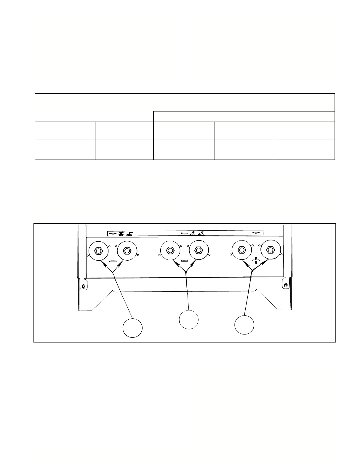
Output Connections
See Figure 2 for locations of the various case front
connection points.
RECOMMENDED CABLE SIZES
(RUBBER COVERED COPPER - RATED 75°C)
Cable Sizes for Combined Length of Work and Electrode Cables
The DC-650 PRO output studs are mounted in pairs.
The two studs in each pair are internally connected to
each other with a buss bar. The studs have a 1/2-13
thread. Output cable lugs must have a hole large
enough to clear a 1/2 inch stud. Choose the cable
size from the table “Recommended Cable Sizes”.
Lengths shown are the total cable length, work cable
length plus electrode cable length.
Output
700A
Output cable strain reliefs are built into the DC-650
PRO base. Feed the output cables up through the
strain relief holes before connecting to the output
studs. This will prevent damage to the studs and the
cables in the event the cables are pulled or stretched.
Duty Cycle
100%
(2 - 70 mm
0 - 100 ft
(0 - 30 m)
2 - 2/0
100 - 200 ft
(30 - 60 m)
2
)
The positive connections can be made to the pair of
studs on the lower right of the case front, marked “+”
(#5, Figure 2). Connection can be made to either or
both of the “+” studs.
2 - 3/0
(2 - 95 mm2)
200 - 250 ft
(60 - 75 m)
2 - 4/0
(2 - 120 mm2)
There are two pairs of studs for the negative
connection. It is important to use the correct pair of
studs, depending on the processes in use. NOTE:
DO NOT CONNECT BOTH PAIRS OF NEGATIVE
STUDS TOGETHER. USE EITHER ONE PAIR, OR
THE OTHER, BUT NEVER CONNECT BOTH PAIRS
TO THE WORKPIECE AT THE SAME TIME. Doing
so will adversely affect the output characteristics of
the machine, giving poor welding performance.
Figure 2
– 11 –
Note that the center pair is labeled “-” and “GMAW
FCAW” (#4, Figure 2). This pair is to be used for
constant voltage processes requiring low output
inductance, such as gas metal arc welding, and fluxcored arc welding.
The left hand pair is labeled “-” and “SAW, SMAW”
(#3, Figure 2). This pair is to be used for constant
current processes, such as stick welding, as well as
for submerged arc welding on constant voltage.
Page 12

Wire Feeder Control Cable Connections
Lincoln wire feeders can be hooked up to either the
14-pin Wire Feeder Receptacle (#12, Figure 3), or to
the terminal strip (behind #11, Figure 3). The Wire
Feeder Receptacle is the preferred method, because
it virtually eliminates accidental miswirings.
DC-650 PRO
Figure 3
For connection to the Wire Feeder Receptacle, choose a control cable from the chart below:
Wire Feed Unit Current Capacity Duty Cycle Cable Type *
LN-7
LN-8 / LN-9
NA-5
400A
600A
1000A
60%
60%
80%
K480-XX
K595-XX
K597-XX
* Cables are available in various lengths. Consult your welding equipment distributor for availability.
For connection to the terminal strip, consult your
Lincoln distributor for the appropriate wire feeder
control cable. Feed the control cable end through the
box connector on the case front, to provide a strain
leads A, B, and C, connect A to 75, B to 76 and C to
77, connect lead 2 to terminal 2, lead 4 to terminal 4,
etc. Connect the green ground lead to the stud
marked .
relief for the cable. Connect the numbered leads in
the control cable to the terminals on the terminal strip,
as depicted in Figure 4. For example, for cables with
– 12 –
Page 13

Connection of a K775 Remote Output
Control
Feed the remote control cable through the box
connector on the case front, to provide a strain relief
for the cable. Connect the numbered leads in the
control cable to the like numbered terminals on the
right hand terminal strip (75 to 75, 76 to 76, and 77 to
77). Connect the green ground lead to the stud
marked .
Connection to Auxiliary Power
The DC-650 PRO has an extra 15 amps of 115 amp
VAC auxiliary power, above what is required for wire
feed equipment. This auxiliary supply is available on
terminals 33 and 34 on the terminal strip. This supply
is protected by a 15 amp circuit breaker.
EXPLANATION OF CONTROLS
Refer to Figure 3 for placement of the DC-650 PRO
controls.
1. Output Control Potentiometer
Controls the output of the machine. Adjusts
current when welding in the SMAW mode, and
adjusts voltage when welding in the GMAW,
FCAW and SAW modes. The Output Control
switch must be in the Local position for this
control to be active.
2. Output Control Switch
This switch chooses whether the DC-650 PRO
output is adjusted from the front panel or by
remote control. In the Local position, the Output
Control Potentiometer adjusts the output. In the
Remote position, the output is adjusted by either
a wire feeder or an optional remote control. If
using an LN-9 or NA-5 see “Operating with LN-9
or NA-5 Wire Feeder” section.
Figure 4
3. Arc Force Potentiometer
Active only in the SMAW (stick) mode. Adjusts
the slope of the machine to give greater short
circuit currents, necessary when using certain
manual electrodes. When set to “0”, there is no
arc force action, giving a soft, buttery arc
characteristic. When adjusted towards “10”, the
higher arc force action gives the arc a “digging”
characteristic, which can help prevent the
electrode from sticking to the work. The setting of
this control has no effect in any other mode.
4. LN-9 / NA-5 On/Off Switch
This switch is set to “On” only when used with
LN-9 and NA-5 wire feed units. For all other
equipment, this switch is to be set to “Off”. For
proper operating with LN-9 and NA-5 wire feed
units, the Output Control switch must be set to
Remote, and the LN-9/NA-5 switch must be set to
“On”.
– 13 –
Page 14

5. Mode Switch
This switch chooses the proper welding mode.
Choose from GMAW (MIG), FCAW (flux-cored),
SAW (submerged arc), or SMAW (stick). This
switch electronically changes the welding
characteristics depending on the mode setting.
NOTE: The welding cables must also be attached to
the proper output studs for best welding
performance (See “Output Connections”
section).
6. Wire Feeder Voltmeter Switch
This switch changes the polarity of the wire feeder
voltmeter sense lead, if the wire feeder is so
equipped. Set to match the electrode polarity so
that the wire feeder voltmeter can display the
welding voltage. This switch has no effect on the
welding output polarity of the DC-650 PRO.
7. Output Terminals Switch
This switch controls the solid-state output
contactor circuitry in the DC-650 PRO. When set
to the “On” position, the output studs are "hot" all
of the time. When in the remote position, the
contactor circuitry is controlled by the equipment
connected to terminals 2 and 4, usually a wire
feeder. Normally, this switch is turned “On” only
when stick welding, arc gouging, or when using
an arc powered wire feeder (such as an LN-25).
8. Power Switch and Pilot Light
Turns the DC-650 PRO on and off. The red pilot
light illuminates when the machine is turned “On”.
9. Circuit Breakers
These circuit breakers provide overload protection
for the auxiliary circuits. One 15 amp breaker is
for the wire feeder 115V AC circuit (31 and 32),
another 15 amp breaker is for the spare 115V AC
auxiliary circuit (33 and 34). The 10 amp breaker
is for the 42V AC wire feeder circuit (41 and 42).
10. Strain Reliefs
These strain reliefs are provided for control cables
going to the terminal strips.
11. Terminal Strip Door
This access door provides protection for the
terminal strip connections. (Lead numbers shown
for this panel in Figure 3). The door can be
opened by turning the fastener one-quarter turn
counter-clockwise. Reverse this procedure to
latch the door shut.
12. Wire Feeder Receptacle
This is the standard Lincoln, 14-pin, MS-type
(amphenol) receptacle. See the DC-650 PRO
wiring diagram for the pinout diagram of this
receptacle.
13. Rating Plate
This plate contains important information
regarding the code number, serial number, input
voltages, input currents, and output ratings of the
DC-650 PRO. Record the code and serial
numbers in a safe place. These numbers will be
required if replacement parts are needed in the
future.
14. Digital Ammeter
Displays the output amperage when welding. If
set to the SMAW (stick) mode, the ammeter
displays the preset welding current when not
welding. By using this meter, the output current
can be set to a predetermined value before an
arc is struck. This permits repeatability when
changing and setting procedures. The output
current can be preset from the Output Control or
from a remote control attached to the terminal
strip.
15. Digital Voltmeter
Displays the output voltage as measured on the
output studs of the machine.
NOTE: Due to voltage drops in the welding
cables and at cable connection points,
the actual arc voltage may be lower than
that displayed on the voltmeter. Use
welding cables of the proper capacity
and make sure all connections are tight
to minimize this effect.
If set to either the GMAW, FCAW, or SAW
modes, this meter can display the preset welding
voltage when the secondary output contactor is
open (usually when the gun trigger is released).
By using this meter, the output voltage can be
set to a predetermined value before an arc is
struck. This permits repeatability when changing
and setting procedures. The output voltage can
be preset from the Output Control or from a
remote control attached to the terminal strip. The
only exception occurs when the DC-650 PRO is
used with an LN-9 or NA-5; with those wire
feeders, the preset voltage can only be read on
the wire feed unit. The DC-650 PRO voltmeter
will display “---” when in the LN-9/NA-5 mode.
(see “Operation with LN-9 or NA-5 Wire Feeder”
section).
– 14 –
Page 15

OPERATING INSTRUCTIONS
WARNING
ELECTRIC SHOCK can kill.
• Do not touch electrically live parts or
electrode with skin or wet clothing.
• Insulate yourself from work and
ground.
• Always wear dry insulating gloves.
------------------------------------------------------------------------
FUMES AND GASES can be
dangerous.
• Keep your head out of fumes.
• Use ventilation or exhaust to remove
fumes from breathing zone.
------------------------------------------------------------------------
WELDING SPARKS can cause fire or
explosion.
• Keep flammable material away.
• Do not weld on closed containers.
GMAW (MIG) Operation
Properly connect a wire feeder control cable to either
the terminal strip or to the Wire Feeder Receptacle.
If welding electrode positive, connect the electrode
cable to the “+” output studs. Connect the work cable
to the center output studs, labeled “GMAW, FCAW”.
Do not make any connections to the left hand pair of
output studs.
Set the control panel switches as follows:
-----------------------------------------------------------------------Mode: GMAW
------------------------------------------------------------------------
Output Local or Remote (See “Output Control
Control: Switch”)
------------------------------------------------------------------------
ARC RAYS can burn eyes and skin.
• Wear eye, ear and body
protection.
------------------------------------------------------------
See additional warning information at
front of this operator’s manual.
-----------------------------------------------------------
-----------------------------------------------------------------------LN-9/NA-5: Off, unless an LN-9 or NA-5 is being
used.
------------------------------------------------------------------------
Wire Feeder Set to match the electrode polarity.
Voltmeter:
------------------------------------------------------------------------
Output
Terminals: Remote
------------------------------------------------------------------------
If using Local output control, preset the desired
welding voltage using the Output potentiometer and
the voltmeter. If using Remote Output control, preset
the welding voltage using a remote control, or with the
voltage control on the wire feeder. If using an LN-9,
see “Operation with LN-9 or NA-5 Wire feeder”
section.
– 15 –
Set up the wire feeder according to the wire feeder
instruction manual.
When the gun trigger is pulled (or the weld sequence
is started) and an arc is struck, the voltmeter will
display the welding voltage preset at the output studs
of the DC-650 PRO, and the ammeter will display the
output current.
Page 16

FCAW (Flux-Cored) Operation
SAW (Submerged Arc) Operation
Properly connect a wire feeder control cable to either
the terminal strip or to the Wire Feeder Receptacle.
If welding electrode positive, connect the electrode to
the “+” output studs, and connect the work cable to
the “-” studs labeled “GMAW, FCAW”. If welding
electrode negative, reverse the connections. Do not
make any connections to the left hand pair of output
studs.
Set the control panel switches as follows:
-----------------------------------------------------------------------Mode: FCAW
------------------------------------------------------------------------
Output Local or Remote (See “Output Control
Control: Switch”)
-----------------------------------------------------------------------LN-9/NA-5: Off, unless an LN-9 or NA-5 is being
used.
Properly connect a wire feeder control cable to either
the terminal strip or to the Wire Feeder Receptacle.
If welding electrode positive, connect the electrode
cable to the “+” output studs, and connect the work
cable to the “-” studs labeled “SMAW,SAW” . If
welding electrode negative, reverse the connections.
Do not make any connections to the center pair of
output studs.
Set the control panel switches as follows:
-----------------------------------------------------------------------Mode: SAW
------------------------------------------------------------------------
Output Local or Remote (See “Output Control
Control: Switch”)
-----------------------------------------------------------------------LN-9/NA-5: Off, unless an LN-9 or NA-5 is being
used.
------------------------------------------------------------------------
Wire Feeder Set to match the electrode polarity.
Voltmeter:
------------------------------------------------------------------------
Output
Terminals: Remote
------------------------------------------------------------------------
If using Local output control, preset the desired
welding voltage using the Output potentiometer and
the voltmeter. If using Remote Output control, preset
the welding voltage using a remote control, or with the
voltage control on the wire feeder. If using an LN-9
and NA-5, see “operation with LN-9 or NA-5 Wire
Feeder” section.
Set up the wire feeder according to the wire feeder
instruction manual.
When the gun trigger is pulled (or the weld sequence
is started) and an arc is struck, the voltmeter will
display the welding voltage present at the output studs
of the DC-650 PRO, and the ammeter will display the
output current.
------------------------------------------------------------------------
Wire Feeder Set to match the electrode polarity.
Voltmeter:
------------------------------------------------------------------------
Output
Terminals: Remote
------------------------------------------------------------------------
If using Local output control, preset the desired
welding voltage using the Output Potentiometer and
the voltmeter. If using Remote output control, preset
the welding voltage using a remote control, or with the
voltage control on the wire feed unit. If using an LN-9
or NA-5, see “Operation with LN-9 or NA-5 Wire
Feeder “ section.
Set up the wire feed unit according to the wire feeder
instruction manual.
When the gun trigger is pulled (or the weld sequence
is started) and an arc is struck, the voltmeter will
display the welding voltage present at the output studs
of the DC-650 PRO, and the ammeter will display the
output current.
– 16 –
Page 17

SMAW (Stick) Operation
If welding electrode positive connect the electrode
cable to the “+” output studs, and connect the work
cable to the “-” studs labeled “SMAW,SAW” . If
welding electrode negative, reverse the connections.
Do not make any connections to the center pair of
output studs.
Set the control panel switches as follows:
Operation with an LN-9 or NA-5 Wire
Feeder
NOTE: Conversion Kits are required for LN-9’s and
NA-5’s used with the DC-650 PRO.
For LN-9 and LN-9GMA model codes above 9100
order K442-1.
For LN-9 models below code 9100 order K442-2.
For NA-5 models below code 9100, order K442-3.
For NA-5 models above code 9100, order K442-4.
-----------------------------------------------------------------------Mode: SMAW
------------------------------------------------------------------------
Output Local or Remote (See “Output Control
Control: Switch”)
-----------------------------------------------------------------------LN-9/NA-5: Off
------------------------------------------------------------------------
Wire Feeder Has no effect in the SMAW mode.
Voltmeter:
------------------------------------------------------------------------
Output
Terminals: On
------------------------------------------------------------------------
If using Local output control, preset the desired
welding voltage using the Output Potentiometer and
the voltmeter. If using Remote output control, preset
the welding voltage using a remote control.
Setup and Operation
These wire feeders are called presettable wire
feeders. The welding voltage is set on the wire
feeder, and then maintained throughout the weld by
circuitry in the wire feeder. It makes continuous
adjustments during the weld to maintain the proper
arc voltage. Because the wire feeder takes control of
the arc voltage, the DC-650 PRO must be told that an
LN-9 or NA-5 is in control. This is done by setting the
LN-9/NA-5 On/Off switch to the “On” position.
To use an LN-9 or NA-5, the Output Control switch
must be set to “Remote”. Output voltage control is
now done through the terminal strip, or through the
wire feeder receptacle, rather than with the front panel
Output potentiometer. Additionally, the LN-9/NA-5
switch must be set to “On”. This tells the DC-650
PRO that an LN-9 or NA-5 is in control. The DC-650
PRO Voltmeter will no longer display the preset
welding voltage. The preset welding voltage must be
read at the LN-9 or NA-5. The DC-650 PRO
Voltmeter will display “---” when not welding.
When welding, the Voltmeter displays the welding
voltage, as measured on the output studs of the DC650 PRO.This voltage may be higher than that
displayed on the LN-9 or NA-5, due to voltage drops
in the cables and cable connection points. The
ammeter displays the actual welding current.
Set the Arc Force potentiometer according to the arc
characteristics desired. With certain electrodes, such
as low hydrogen alloy electrodes, it is beneficial to set
the Arc Force to a high setting. This gives a more
forceful arc, less prone to sticking and stubbing.
Setting this control too high can lead to excessive
spatter. It is often best to start stick welding with the
Arc Force set to minimum, and if sticking is a problem,
raise the setting until the electrode runs smoothly.
The output terminals will always be “hot”. Before an
arc is struck, the ammeter will display the preset
current. When an arc is struck, the ammeter will
display the actual output current. In the SMAW mode,
the voltmeter always displays the output voltage
present at the output studs of the DC-650 PRO.
Connection of the Work Lead (21)
In some applications, very precise arc voltage sensing
is required. This requires that the wire feeder arc
voltage sensing lead, number 21, be extended directly
to the workpiece. Instructions follow for extending that
lead.
When using the Wire Feeder Receptacle, extend the
21 lead to the workpiece as follows:
1. Turn the input power off.
2. Open the terminal strip door. When installing the
wire feeder, do not connect the lead marked 21
coming from the wire feeder control cable to the
– 17 –
Page 18

terminal strip. (See Figure 4). Instead, extend the
wire feeder control cable 21 lead to the workpiece.
Insulate the 21 lead connection with tape or other
means to achieve 300V withstand capability.
The LN-9 or NA-5 will now sense arc voltage through
this work sense lead. The DC-650 PRO meters will
continue to read the output stud voltage, so there may
be a difference between the DC-650 PRO voltmeter
and the wire feeder voltmeter.
When using the terminal strip for wire feeder
connection, extend the 21 lead to the workpiece as
follows:
1. Turn the input power Off.
2. Open the terminal strip door. When installing the
wire feeder, do not connect the lead marked 21
coming from the wire feeder control cable to the
terminal strip. (See Figure 4). Instead, extend the
wire feeder control cable 21 lead to the workpiece.
Insulate the 21 lead connection with tape or other
means to achieve 300V withstand capability.
The LN-9 or NA-5 will now sense arc voltage through
this work sense lead. The DC-650 PRO meters will
continue to read the output stud voltage, so there may
be a difference between the DC-650 PRO voltmeter
and the wire feeder voltmeter.
Set the control panel switches as follows:
-----------------------------------------------------------------------Mode: GMAW
------------------------------------------------------------------------
Output Local or Remote (See “Output Control
Control: Switch”)
-----------------------------------------------------------------------LN-9/NA-5: Off
------------------------------------------------------------------------
Wire Feeder Has no effect when arc gouging.
Voltmeter:
------------------------------------------------------------------------
Output
Terminals: On
-----------------------------------------------------------------------If using Local output control, preset the desired voltage
(approximately 40 volts) using the Output potentiometer and
the volt meter. If using Remote output control, preset the
voltage using a remote control. Begin gouging, and then
adjust the output up or down as necessary.
Installation with an NA-3
As supplied from the factory, the cold inch feature in
the NA-3 will not work when used with a DC-650 PRO
in negative polarity operation. Contact the factory for
information regarding an NA-3 modification procedure
that will allow the cold inch feature to work with the
DC-650 PRO under these conditions.
K317 DUAL PROCESS KIT (FOR WIRE
FEEDERS USING SAME POLARITY
This kit permits the connection of two wire feeders to
the DC650 PRO. Both feeders will weld with the same
electrode polarity. When the trigger of the desired wire
feeder is pressed, the DC650 PRO output control
leads (75, 76, and 77) will be connected to that feeder
and the procedure as set on its controls will be
provided. The other connected wire feeder will not be
feeding wire but is electrically hot. The kit mounts at
the power source and is connected to the power
source terminal strip with the supplied leads.
Installation instructions are included with the kit.
NOTE: When using the DC650 PRO power source the
K317 Dual Process Kit can only be used with two like
wire feeders. An LN-9 cannot be used with an LN-8.
Only two LN-9’s may be used together or two LN-8’s
together.
AC-A (Arc Gouging) Operation
Most arc gouging is done with constant voltage
output. Connect the electrode lead to the “+” output
studs, and the work lead to the “-” studs labeled
“GMAW, FCAW”. Do not make any connections to
the left hand pair of output studs.
Dec 95
PROTECTIVE CIRCUITRY
Thermostatic Protection
The DC-650 PRO has a thermostat in both the
primary and secondary circuits.
The primary thermostat, located inside the right
primary coil, will open up if the main transformer
overheats. The machine will completely shut off when
the primary thermostat opens. The machine must be
allowed to cool before it can be restarted.
The secondary thermostat, located on the secondary
common lead at the front of the main transformer, will
open if the output is overloaded, the duty cycle is
exceeded, or if the flow of cooling air is blocked.
When the secondary thermostat opens, power will be
removed from control transformer T3, causing the
Control PC Board to lose power. The meter displays
will go off, and there will be no output from the DC650 PRO. The pilot light will remain lit, and the fan
will continue to run. When the machine cools down,
the thermostat will close automatically, and normal
operation will be restored.
– 18 –
Page 19

Overload Protection
The DC-650 PRO is protected from excessive output
currents by phaseback circuitry on the Control PC
board. If the output current exceeds approximately
850 amps, the output of the machine will phase back
to a low value. It will remain at a low value until the
load is removed.
If the output is shorted in one of the constant voltage
modes (GMAW, FCAW, or SAW) the output may
phase back all the way to zero. The short must be
removed from the output, and the protective circuits
reset before welding can continue. To reset them,
shut the DC-650 PRO off, and then turn it back on
again.
Routine Maintenance
1. The fan motor has sealed bearings which require
no service.
2. In extremely dusty locations, dirt may clog the air
channels causing the welder to run hot. Blow out
the machine at regular intervals.
3. In extremely dusty locations, dirt may accumulate
on the remote control terminal strip. Wipe or blow
this terminal strip off at regular intervals. This is
particularly important in damp locations
TROUBLESHOOTING
WARNING
ELECTRIC SHOCK can kill.
• Have a qualified individual install and
service this equipment.
• Turn the input power off at the fuse
box before working on equipment.
• Do not touch electrically hot parts.
---------------------------------------------------------------------
Power Source Troubleshooting
Most welding equipment problems, particularly in new
installations, can be traced to incorrect installation or
incorrect procedures. Be sure that the DC-650 PRO
is properly connected, all accessories and wire
feeders are working correctly, and that valid welding
procedures are being used.
– 19 –
Dec 95
Page 20

TROUBLESHOOTING
TROUBLE
A. Input contactor chatters.
B. Machine input contactor does
not operate.
CAUSE
1. Faulty input contactor.
2. Low line voltage.
3. Pilot transformer (T2) misconnected.
1. Supply line fuse blown.
2. Contactor power circuit dead.
3. Broken power lead.
4. Wrong input voltage.
5. Primary thermostats open.
6. Open input contactor coil.
7. Power ”On/Off” switch (S1) not
closing.
WHATTODO
1. Refer to wiring diagram &
2. Check input power.
3. Check input connection instructions
1. Replace if blown-look for reason first.
2. Check pilot transformer T2 and
3. Check input voltage at contactor.
4. Check voltage against instructions.
5. Check for overheating; make sure fan is
6. Replace coil.
7. Replace switch.
check related leads.
.
associated leads.
operating and there is no obstruction to free
air flow. Replaces faulty thermostat.
C. Machine input contactor
operates, but no output when
trying to weld.
D. Machine has high output and
no control.
1. Electrode or work lead loose or
broken.
2. Open main transformer (T1)
primary or secondary circuit.
3. Defective Control P.C. Boards.
4. Output terminals switch set
wrong or faulty.
5. Secondary thermostat open.
1. Fault in leads 75, 76, or 77.
2. Open in feedback circuity.
1. Repair connection.
2. Repair.
3. Replace. See P.C. Board
Troubleshooting Procedure.
4. Check setting/operation of the
Output Terminals switch.
5. Check for overheating; make sure fan is
operating and there is no obstruction to free
air flow. Replaces faulty thermostat.
1. Check wiring.
2. Check control and protection PC Baord
wiring. With input power off, check for
continuity between (+) output stud and lead
and 1J12 on the control board. Also check for
continuity between GMAW/FCAW (-) output
stud and 3J12 on the control board. Finally,
check for continuity between SMAW/SAW (-)
output stud and 2J12. Repair if necessary.
CAUTION
If for any reason you do not understand the test procedures or are unable to perform the tests/repairs safely, contact your
Local Lincoln Authorized Field Service Facility for technical troubleshooting assistance before you proceed.
– 20 –
Page 21

TROUBLESHOOTING
TROUBLE
E. Machine has low output and
no control.
F. Machine does not have
maximum output.
CAUSE
1. Output control Local/Remote
switch in wrong position.
2. Output control switch faulty.
3. Fault in leads 75,76, or 77.
4. Faulty Control P.C. Board.
5. Output control potentiometer
circuit open (lead 75).
1. One input fuse blown.
2. One phase of main transformer
open.
3. Faulty Control P.C. Board.
WHATTODO
1. Check position of switch.
2. Check switch and replace if faulty.
3. Check wiring.
4. Replace. See P.C. Board
Troubleshooting Procedure.
5. Check and replace
potentiometer if faulty. Check
wiring of lead #75.
1. Check and replace if blown
after checking for reason for
blown fuse.
2. Check for open and repair.
3. Replace. See P.C. Board
Troubleshooting Procedure.
G. Machine will not shut off.
H. Variable or sluggish welding
arc.
4. Output control potentiometer.
5. Output control potentiometer
lead 75 open.
6. Defective main SCR bridge.
1. Input contactor contacts frozen.
2. Defective On/Off switch, S-1.
1. Poor work or electrode
connection.
2. Welding leads too small.
3. Welding current or voltage too
low.
4. Leads or connections open in control
circuit.
4. Check and replace if faulty.
5. Check and repair broken leads.
6. Check and replace if defective.
1. Check and replace if
2. Replace.
1. Check & clean all connections.
2. Check table in instruction manual.
3. Check procedures for
4. Check & replace if defective.
necessary.
recommended settings.
5. LN-9/NA-5 switch in wrong position.
5. Only connect one pair of
negative studs to the work.
CAUTION
If for any reason you do not understand the test procedures or are unable to perform the tests/repairs safely, contact your
Local Lincoln Authorized Field Service Facility for technical troubleshooting assistance before you proceed.
– 21 –
Page 22

TROUBLESHOOTING
TROUBLE
I. Output control not functioning
on the machine.
J. Output control not functioning
on remote control.
CAUSE
1. Output control switch in wrong
position.
2. Faulty output control switch.
3. Faulty output control
potentiometer.
4. Leads or connections open in
control circuit.
5. LN-9/NA-5 switch in wrong
position.
6. Faulty Control P.C. Board.
1. Output control switch in wrong
position.
2. Faulty output control switch.
WHATTODO
1. Place switch in “Local” position.
2. Check & replace if found faulty.
3. Check & replace if found faulty.
4. Check lead continuity and
connections for an open and
repair if necessary.
5. Set to “Off” when not using an
LN-9/NA-5.
6. Replace. See P.C. Board
Troubleshooting Procedure.
1. Place switch in “Output Control
Remote”.
2. Check & replace if found faulty.
K. Digital meters do not light
- or -
Digital meter display is
incorrect.
L. Poor arc striking with
semiautomatic wire feeders.
3. Faulty remote control
potentiometer.
4. Leads or connections open in
control circuit.
5. Faulty Control P.C. Board.
1. Faulty Meter P.C. Board.
2. Faulty Control P.C. Board.
3. Secondary thermostat is open.
1. Poor work connection.
3. Check & replace if found faulty.
4. Check all leads and
connections, internal or remote,
for continuity; repair if
necessary.
5. Replace. See P.C. Board
Troubleshooting Procedure.
1. Replace. See P.C. Board
Troubleshooting Procedure.
2. Replace. See P.C. Board
Troubleshooting Procedure.
3. See “Thermostatic Protection”
section.
1. Work connection must be
adequate for application.
2. Improper procedures.
3. Defective P.C. Board.
– 22 –
2. Adjust procedures for improved
starting.
3. Replace. See P.C. Board
Troubleshooting Procedure.
Page 23

TROUBLESHOOTING
TROUBLE
M. Poor arc characteristics in
GMAW mode.
N. Ammeter displays “Err” and
Voltmeter displays a number
ACCESSORY TROUBLESHOOTING
TROUBLE
CAUSE
1. Capacitor bank not switching in.
2. Capacitor(s) in output circuit failed. A failure
is indicated if the small vent plug on top of a
capacitor is raised or blown out.
1. An error has been detected.
CAUSE
WHATTODO
1. Check the Mode SCR (SCR7). Should be on
when in GMAW and FCAW modes.
2. Replace entire bank of capacitors. Do not
replace individual capacitors.
WARNING: The liquid electrolyte in these
capacitors is toxic. Avoid contact with any
portion of your body. Clean up vented
electrolyte using rubber gloves and a water
dampened cloth. Remove any electrolyte
which gets on skin using soap and water.
1. See Error code Troubleshooting Guide.
WHATTODO
A. Output Control not functioning
on Remote Control.
B. Output Control not functioning
on the machine.
1. Output Control switch in wrong
position.
2. Faulty Output Control switch.
3. Faulty Remote Control
potentiometer.
4. Leads or connections open in
control circuit.
5. Faulty Control P.C. Board.
1. Output Control switch in the
wrong position.
2. Faulty Output Control switch.
3. Faulty Output Control
potentiometer.
1. Place switch in “Remote”.
2. Check & replace if found faulty.
3. Check & replace if found faulty.
4. Check all leads & connections.
5. See P.C. Board
Troubleshooting Procedure.
1. Place switch in “Local” position.
2. Check & replace if found faulty.
3. Check & replace if found faulty.
CAUTION
If for any reason you do not understand the test procedures or are unable to perform the tests/repairs safely, contact your
Local Lincoln Authorized Field Service Facility for technical troubleshooting assistance before you proceed.
– 23 –
Page 24

TROUBLESHOOTING
Observe all Safety Guidelines detailed througout this manual
ERROR CODES DISPLAYED ON VOLTMETER WHEN AMMETER DISPLAYS “ERR”
The DC-650 PRO Meter PC Board displays error codes when certain trouble conditions exist. The error codes,
trouble conditions, and possible remedies are listed below.
ERROR
CODE
Err 000
Err 013
Err 014-016
Err 023
Err 030
TROUBLE REMEDY
1. Output overload.
2. Shunt miswired or unconnected.
3. Faulty Control PC Board.
1. Missing Phase Signal.
2. Faulty Control PC Board.
1. Faulty Control PC Board.
1. Noisy line.
2. Faulty Control PC Board.
1. Control transformer miswired.
1. Reduce output overload.
2. Check shunt and wiring. Repair if necessary.
3. Replace, See PC Board Troubleshooting Procedure.
1. Check for 66 VAC ±10% between leads 329 and 332
of J12 at control board. Repair if necessary.
2. Replace. See PC Board Troubleshooting Procedure.
1. Replace. See PC Board Troubleshooting Procedure.
1. Make sure machine frame is grounded. See
installation section on minimizing problems due to
high frequency interference.
2. Replace. See PC Board Troubleshooting Procedure.
1. Swap leads 330 and 332A at Control Transformer T3
in the control box.
Err 100-131
Err 200-206
2. Main Transformer Auxiliary
miswired.
3. Faulty Control PC Board.
1. Mode Switch is set between two positions.
2. Faulty Mode Switch.
3. Mode Switch wiring bad.
4. Faulty Control Board.
1. Noisy input line.
2. Faulty Control PC Board.
2. Check leads 29, 30B, and 32B from main
transformer. Repair if necessary.
3. Replace. See PC Board Troubleshooting Procedure.
1. Reposition mode switch.
2. Check and replace if found faulty.
3. Check all leads for continuity. Repair if necessary.
4. Replace. See PC Board Troubleshooting Procedure.
1. Make sure machine frame is grounded. See
installation section on minimizing problems due to
high frequency interference.
2. Replace. See PC Board Troubleshooting Procedure.
CAUTION
If for any reason you do not understand the test procedures or are unable to perform the tests/repairs safely, contact your
Local Lincoln Authorized Field Service Facility for technical troubleshooting assistance before you proceed.
– 24 –
Page 25

Procedure for Troubleshooting PC Boards
WARNING
ELECTRIC SHOCK can kill.
• Have a qualified individual install and
service this equipment.
• Turn the power source input power off
at the disconnect switch before
working on this equipment.
• Do not touch electrically hot parts.
---------------------------------------------------------------------
Before replacing a PC board which is suspected of
being defective, visually inspect the PC board in
question for any electrical or mechanical damage to
any of its components and conductors on the back of
the board.
a. If there is no
install a new one and see if this remedies the
problem. If the problem is remedied, reinstall the
old
PC board to see if the problem still exists. If it
does no longer exist with old PC board:
1. Check the PC board harness connector pins for
corrosion, contamination, or looseness.
2. Check leads in the plug harness for loose or
intermittent connection.
b. If PC board is visibly damaged electrically
possibly subjecting the new PC board to the same
cause of failure, check for possible shorts, opens,
or grounds caused by:
1. Frayed or pinched lead insulation.
2. Poor lead termination, such as a poor contact
or a short to adjacent connection or surface.
3. Shorted or open motor leads, or other external
leads.
visible damage to the PC board,
, before
4. Foreign matter or interference behind the PC
boards.
c. If PC board is visibly damaged mechanically,
inspect for cause, then remedy before installing a
replacement PC board.
If there is damage to the PC board or if replacing
PC board corrects problem, return it to the local
Lincoln Electric Field Service Shop.
CAUTION
If for any reason you do not understand the test procedures or are unable to perform the tests/repairs safely, contact your
Local Lincoln Authorized Field Service Facility for technical troubleshooting assistance before you proceed.
– 25 –
Page 26

Protection PC Board
The protection PC Board is located on the back of the
control box. It protects the PC Board from electrical
noise. Most of the circuits on the Protection board are
straight through connections. The board can be
checked out in the field with a continuity tester or an
ohmmeter. A copy of the DC-650 PRO wiring
diagram is needed also. All circuits should show
continuity, or nearly zero ohms resistance, from input
to output. Inputs and outputs can be identified by the
common lead number suffixes on the wires connected
to the Protection PC Board. For example, lead 75 on
the input side is common with lead 375A on the output
side. Lead 208 is common with 308, lead 209 is
common with 309 and 309A, etc.
If one control or function of the machine does not
appear to be working, it is best to trace out the wiring
associated with that function, switch or potentiometer
all the way back to the Control board with an
ohmmeter. If all check out there, verify that the
following voltages are present at the output of the
auxiliary transformer, T3.
Auxiliary Transformer (T3) Plug P8 Approximate
Secondary Lead Color Locations Voltage
Red to Red 7 to 9 36V AC
Red to White 7 to 8 18V AC
Yellow to Yellow 1 to 2 10V AC
Black to Black 5 to 6 24V AC
Orange to Orange 3 to 4 18V AC
Snubber PC Board
The snubber PC Board is located on the main rectifier.
Circuits on this board protect the SCR’s from high
transient voltages. Failures on this board should be
very rare. The only way to check the seven circuits on
this board is to check each circuit, one at a time, using
an ohmmeter, preferably an analog ohmmeter on the
X10 scale. The first step is to connect one lead of the
ohmmeter to the center plate of the rectifier assembly.
This is the cathode connection for SCR’s 1 through 6.
Next, disconnect the Snubber board lead that goes to
the anode of SCR1. Connect the other ohmmeter
lead to this snubber lead. The ohmmeter should show
a low resistance initially, then swing towards high
resistance if the snubber is good. Repeat this with
SCR;’s 2 through 6, each time testing just one
Snubber lead. Lastly, disconnect the snubber lead
that goes to the cathode of SCR7, and perform the
same test. The ohmmeter action should be the same
for each SCR on the bridge.
Output Bypass PC Boards
One of these boards is mounted to each output
terminal. Each board prevents high frequency energy
and electrical noise from entering the DC-650 PRO.
Again, failures of these boards should be very rare.
The only way to inspect these boards is visually.
Inspect each board, looking for burnt traces or
components.
Control PC Board
This board, located inside the control box, is the heart
of the machine. All welding output is controlled by this
board. The Meter boards receive their information
from the Control board as well. Very little external
diagnostic work can be performed on this board.
Often, replacement with a known good board is the
best service method. Remove the board that is
suspected to be defective. Carefully look over the
board, checking for burnt traces or components. If
none are found, install the known good board. If the
trouble goes away, reinstall the suspected bad board
to confirm that the board was indeed at fault. If the
problem is now gone with the original board installed,
the problem is probably with one of the leads or
connectors going to the board.
Meter PC Board
Both the Voltmeter and the Ammeter PC boards are
identical. They both operate as display boards,
displaying numbers sent to them by the Control PC
board. The Meter boards do not make voltage or
current measurements; the Control Board performs
those functions.
If both meter boards are dark, (not lighted) chances
are that either the secondary thermostat is open (see
“Thermostatic Protection” section), the auxiliary
transformer T3 is defective (see “Control P.C. Board”
section) or the Control board is defective.
If only one board is dark, make sure the machine is in
a mode where both boards are supposed to light.
There are certain modes where one board or the
other is supposed to be dark. To check this, place
the mode switch in the SMAW mode, and set the
Output Control switch to “On”. Both meters should be
lit. If one board is still dark, that board may be
defective. The best way to check this is to switch the
bad board with the other working Meter board right
next to it. Replace the defective board.
CAUTION
If for any reason you do not understand the test procedures or are unable to perform the tests/repairs safely, contact your
Local Lincoln Authorized Field Service Facility for technical troubleshooting assistance before you proceed.
– 26 –
Page 27

PL1
10/50W
50/100W
10K/2W
10K/2W
S
S
4-29-94C
G
REMOTE
CONTROL
RESISTORS = OHMS/WATT UNLESS OTHERWISE SPECIFIED
ALL SWITCH WIRING VIEWED FROM REAR OF SWITCH
(SEE DETAILS)
RECONNECT PANEL
T1
T2
T3
TO SUPPLY
LINES
(SEE DETAILS)
RECONNECT PANEL
GMAW, FCAW
SMAW, SAW
216
209A
200A
324
320
319
318
317
361
362
363
366
364
TERMINAL STRIPS)
(FRONT VIEW OF
TS1
TS2
REMOTE
CONTROL
CUSTOMER
CONNECTIONS
WIRE FEEDER
S6
PROTECTION
P. C. BOARD
++++++
CR2 CR2
CR2
208
G1
G2
G3
G4
G5
G6
211
230
CR2
230A
214
330
332A
T3
18VAC
321
375A
304A
302A
340
342
341
343
344
345
346
347
R2
R1
J12
J13
307A
309A
308
332
329
314
307A
309A
308
332
329
314
317
377
323
322
376
S4
323A
323A
375
302
304
377
375A
302A
321
304A
376
307
G7
29
SCR1
200
D1
D2
211B
221
R4
R5
31,000 uF/50V EACH
75
77
21
2
76
4
77
76
75
21
4
2
H
E
G
F
A
J
C
D
N
KBL
M
I
42VAC
115VAC
77A
76A
75A
41A
42A
77
76
75
21
4
2
A
AAA
A
A
31
32
31
32
33
A
A
41
42
32
41
42
CAA
CONTROL BOX
203
205
SUPPRESSOR
BOARD
SUPPRESSOR
BOARD
BBO
O
(A1)
(A2)
(A3)
(A4)
(A5)
(A6)
G7
(A1)
(A2)
(A3)
(A4)
(A5)
(A6)
204
TOROID
CONTROL
P. C. BOARD
B
W
344
345
346
347
340
342
341
343
CONNECTOR CAVITY NUMBERING SEQUENCE
(COMPONENT SIDE OF P. C. BOARD)
+
-
THERMOSTAT
1
4
7
10
2
5
8
11
3
6
9
12
4 PIN
8 PIN
2
42V
10 PIN
O3
3
1
1
2
3
4
SHUNT
GENERAL INFORMATION
ELECTRICAL SYMBOLS PER E1537
INDUCTOR
OUTPUT
TO GROUND
L2
L1
L3
A
B
C
800 A. 50mV
O1
O2
115V
10VAC
24VAC
1
2
3
4
OUTPUT
CONTROL
ARC
FORCE
SCR7
SCR2
SCR3
SCR4
SCR5
SCR6
G6
G5
G4
G3
G2
G1
+
-
-
-
-
41
31
33
H1
H2
H3
H4
THERMOSTAT
PRIMARY
SECONDARY
R
FAN MOTOR
X1
X2
X2
207
209
36VAC
CT
R
R
W
Y
Y
32B
POWER
RECEPTACLE
21A2A4A
31A
32A
FEEDER
WIRE
BLUE
WHITE
15 AMPS
10 AMPS
15 AMPS
CR1
CR1
-
40
32D
40
30A
30B
30
32
SNUBBER
BOARD
SUPPRESSOR
BOARD
OUTPUT
SWITCH
12 PIN
16 PIN
1 16
8
7
12
916
202
202A
32B
32C
30C
42
J7V
J7A
201
T1
T2
S1
R6
CB1
CB2
CB3
S3
S5
CUSTOMER
GROUND
315
316
320A
324
375
302
304
319
318
320
320A
322
A
B
C
D
E
F
G
H
I
J
K
L
M
N
PHYSICAL LAYOUT
(REAR VIEW)
316
315
S2
1
2
3
4
5
6
7
8
9
10
11
12
MODE
SWITCH
366
361
362
363
364
VOLTMETER
LN-9/NA-5
(SHOWN "ON")
OUTPUT CONTROL
(SHOWN IN "LOCAL")
ON
OFF
115
VAC
115
VAC
42
VAC
1
11
12
13
5
6
J4
G1
G2
G3G4G5
G6
300
310
311
312
313
1
2
3
456
7
8
9
11
12
J2
1
2
3
4
5
6
7
8
9
J1
1
234
5
6
J5
J6
7
8
VOLTMETER
P.C. BOARD
AMMETER
P.C. BOARD
7
89125
6
3
4
J8
10
313
312
311
310
300
G6
G5
G4
G3
G2
G1
1
2
3
4
5
6
7
8
9
11
12
J10
10
10
1
2
3
4
5
6
1
2
10
1
2
3
4
5
6
34
J9
12
34
56
7
8
J11
1
2
345
6
7
8
91011
12
13
14 15
16
J7A,J7V,J13
J5,J9
J1,J8
J2,J10
J4,J11
6 PIN
1
8
7
14
14 PIN
J3
5
8
6
2
3
4
7
9
10
14
13
J3
1
12
11
J3
8/300W
8/300W
WIRE FEEDER
VOLTMETER
9
8
332A
330
234
7
10
14
15
16
NOTE: SINCE COMPONENTS OR CIRCUITRY OF A PRINTED CIRCUIT BOARD
MAY CHANGE WITHOUT AFFECTING THE INTERCHANGEABILITY OF A
COMPLETE BOARD. THIS DIAGRAM MAY NOT SHOW THE EXACT COMPONENTS
OR CIRCUITRY OF CONTROLS HAVING A COMMON CODE NUMBER.
INPUT
LINES
L3
H1
L2
INSULATE WITH TAPE
H2H3H4
L1
INPUT
LINES
L3
L1
H1
L2
H4
INSULATE WITH TAPE
H2
H3
575V/60HZ
460V/60HZ 230V/60HZ
INPUT
LINES
L3
L1
H1
L2
H4
INSULATE WITH TAPE
H2
H3
T1
T2
T3
A
B
C
4
5
6
7
8
9
T1
T2
T3
T1
T2
A
B
C
A
B
4
5
6
4
5
7
8
9
7
8
C69T3
INPUT
LINES
L3
H1
L2
INSULATE WITH TAPE
H2
H3
L1
INPUT
LINES
L3
L1
H1
L2
INSULATE WITH TAPE
H2
H3
T1
T2
T3
4
5
6
7
8
9
T1
T2
T3
4
5
6
7
8
9
230/460/575/60 HZ MACHINES ONLY
J6,J12
2437
R3
ON
REMOTE
308A
307
+ELECTRODE
-ELECTRODE
308A
200
211
29
CONNECTIONS
N.A.
N.A. THIS PERMANENT CONNECTION IS
MADE AT THE MAIN TRANSFORMER
FOR 230/460, AND 230/460/575V
MACHINES ONLY.
INPUT
LINES
L3
H1
L2
INSULATE WITH TAPE
H2
H3
L1
T1
T2
T3
4
5
6
7
8
9
12
10
11
GND
INPUT
LINES
L3
L1
H1
L2
INSULATE WITH TAPE
H2
H3
T1
T2
4
5
7
8
6
9
T3
GND
12
10
11
208V 50 / 60 HZ
416V 50 / 60 HZ
208/416V 60 HZ MACHINES ONLY
230/460V 60HZ MACHINES ONLY
460V 60HZ
230V 60HZ
DC-650 PRO WIRING DIAGRAM
– 27 –
NOTE: This diagram is for reference only. It may not be accurate for all machines covered by this manual. The specific diagram for a particular code is pasted inside
the machine on one of the enclosure panels. If the diagram is illegible, write to the Service Department for a replacement. Give the equipment code number..
Page 28

DIMENSION PRINTS
DC-650 PRO WITH A K817 UNDERCARRIAGE
G
A
22.25
3.25
B
27.50
32.70
39.95
20.00
27.87
N.A. - Optional K-842 Undercarriage also available. See next page.
H
.406 DIA.
MTG. HOLES
F
C
E
GAS CYLINDER
SUPPORT
INCHES 38.00 20.24 40.59 4.75 29.93 39.07 .94 N.A.
(CM) (96.5) (51.4) (103.1) (12.1) (76.0) (99.2) (2.4)
UNITS A B C E F G H NOTE
DC-650 PRO WITH A K842 UNDERCARRIAGE
A
C
E
D
M
P
L
R
FRONT OF
WELDER
S
B
W*
H*
K
J*
* LOCATION OF .406 DIA. MOUNTING HOLES
U*
V
INCHES 54.91 37.86 38.00 5.19 20.24 36.12 .94 49.89 23.28 22.25 11.12 3.25 27.50
(CM) (139.5) (96.2) (96.5) (13.2) (51.4) (91.7) (2.4) (126.7) (59.1) (56.5) (28.2) (8.2) (69.9)
UNITS A B C D E H J K L M P R S
INCHES 7.11 20.00 27.65 29.93
(CM) (18.1) (50.8) (70.2) (76.0)
UNITS T U V W
– 28 –
Page 29

PARTS LIST FOR
DC-650 PRO
AND
DC-750
P-223P-223
This parts list is provided as an informative guide only.
This information was accurate at the time of printing. However, since these
pages are regularly updated in Lincoln Electric’s official Parts Book (BK-34),
always check with your Lincoln parts supplier for the latest parts
11-1-96
Page 30

NOTES
Page 31

Now Available...12th Edition
VISA
®
Mas ter Car dMasterCard
®
The Procedure Handbook of Arc Welding
With over 500,000 copies of previous editions published
since 1933, the Procedure Handbook is considered by many to
be the “Bible” of the arc welding industry.
This printing will go fast so don’t delay. Place your
order now using the coupon below.
The hardbound book contains over 750 pages of welding
information, techniques and procedures. Much of this material
has never been included in any other book.
A must for all welders, supervisors, engineers and
designers. Many welding instructors will want to use the book
as a reference for all students by taking advantage of the low
quantity discount prices which include shipping by
4th class parcel post.
$15.00 postage paid U.S.A. Mainland
How To Read Shop Drawings
The book contains the latest information and application
data on the American Welding Society Standard Welding
Symbols. Detailed discussion tells how engineers and
draftsmen use the “short-cut” language of symbols to pass
on assembly and welding information to shop personnel.
New Lessons in Arc Welding
Lessons, simply written, cover manipulatory techniques;
machine and electrode characteristics; related subjects,
such as distortion; and supplemental information on arc
welding applications, speeds and costs. Practice materials,
exercises, questions and answers are suggested for each
lesson.
528 pages, well illustrated, 6” x 9” size, bound in simulated,
gold embossed leather.
$5.00 postage paid U.S.A.
Mainland
Need Welding Training?
The Lincoln Electric Company operates the oldest and
most respected Arc Welding School in the United States at its
corporate
students have graduated. Tuition is low and the training is
“hands on”
For details write: Lincoln Welding School
headquarters in Cleveland, Ohio. Over 100,000
22801 St. Clair Ave.
Cleveland, Ohio 44117-1199.
Practical exercises and examples develop the reader’s
to visualize mechanically drawn objects as they will appear
in their assembled form.
187 pages with more than 100 illustrations. Size 8-1/2” x
Durable, cloth-covered board binding.
$4.50 postage paid U.S.A.
ability
11”
Mainland
and ask for bulletin ED-80 or call 216-383-2259 and ask
for the
Welding School Registrar.
Lincoln Welding School
BASIC COURSE $700.00
5 weeks of fundamentals
There is a 10% discount on all orders of $50.00 or more for shipment at one time to one location.
Orders of $50 or less before discount or orders outside of North America must be prepaid with charge, check or money order in U.S. Funds Only.
Prices include shipment by 4thClass Book Rate for U.S.A. Mainland Only. Please allow up to 4 weeks for delivery.
UPS Shipping for North America Only. All prepaid orders that request UPS shipment please add:
$5.00 For order value up to $49.99
$10.00 For order value between $50.00 & $99.99
$15.00 For order value between $100.00 & $149.00
For North America invoiced orders over $50.00 & credit card orders, if UPS is requested, it will be invoiced or charged to you at cost.
Outside U.S.A. Mainland order must be prepaid in U.S. Funds. Please add $2.00 per book for surface mail or $15.00 per book for air parcel post shipment.
METHOD OF PAYMENT: (Sorry, No C.O.D. Orders)
CHECK ONE:
Please Invoice (only if order is over $50.00)
Check or Money Order Enclosed, U.S. Funds only
Credit Card - Telephone:_______________________________________________
Account No.
USE THIS FORM TO ORDER:
BOOKS OR FREE INFORMATIVE CATALOGS Telephone: 216-383-2211 or, for fastest service, FAX this completed form to: 216-361-5901.
|_|_|_|_|_|_|_|_|_|_|_|_|_|_|_|_|_|_|_|_|_|
Order from: BOOK DIVISION, The Lincoln Electric Company, 22801 St. Clair Avenue, Cleveland, Ohio 44117-1199
Exp Date
Name: _______________________________________________
Address: _______________________________________________
_______________________________________________
|_|_| |_|_|
Month Year
Signature as it appears on Charge Card:
______________________
Lincoln Welding School Titles: Price Code Quantity Cost
(ED-80)
Seminar Information Procedure Handbook “Twelfth Edition” $15.00 PH
(ED-45)
Educational Video Information Incentive Management $5.00 IM
(ED-93)
James F. Lincoln Arc Welding The American Century of John C. Lincoln $5.00 AC
Foundation Book Information Welding Preheat Calculator $3.00 WC-8
(JFLF-515)
New Lessons in Arc Welding $5.00 L
How to Read Shop Drawings $4.50 H
A New Approach to Industrial Economics $5.00 NA
Pipe Welding Charts $4.50 ED-89
SUB TOTAL
Additional Shipping Costs if any
TOTAL COST
Page 32

WARNING
Spanish
AVISO DE
PRECAUCION
● Do not touch electrically live parts or
electrode with skin or wet clothing.
● Insulate yourself from work and
ground.
● No toque las partes o los electrodos
bajo carga con la piel o ropa
mojada.
● Aislese del trabajo y de la tierra.
● Keep flammable materials away.
● Mantenga el material combustible
fuera del área de trabajo.
● Wear eye, ear and body protection.
● Protéjase los ojos, los oídos y el
cuerpo.
French
ATTENTION
German
WARNUNG
Portuguese
ATENÇÃO
Japanese
Chinese
Korean
Arabic
● Ne laissez ni la peau ni des
vêtements mouillés entrer en contact
avec des pièces sous tension.
● Isolez-vous du travail et de la terre.
● Berühren Sie keine stromführenden
Teile oder Elektroden mit Ihrem
Körper oder feuchter Kleidung!
● Isolieren Sie sich von den
Elektroden und dem Erdboden!
● Não toque partes elétricas e
electrodos com a pele ou roupa
molhada.
● Isole-se da peça e terra.
● Gardez à l’écart de tout matériel
inflammable.
● Entfernen Sie brennbarres Material!
● Mantenha inflamáveis bem
guardados.
● Protégez vos yeux, vos oreilles et
votre corps.
● Tragen Sie Augen-, Ohren- und Kör-
perschutz!
● Use proteção para a vista, ouvido e
corpo.
READ AND UNDERSTAND THE MANUFACTURER’S INSTRUCTION FOR THIS EQUIPMENT AND THE CONSUMABLES TO BE
USED AND FOLLOW YOUR EMPLOYER’S SAFETY PRACTICES.
SE RECOMIENDA LEER Y ENTENDER LAS INSTRUCCIONES DEL FABRICANTE PARA EL USO DE ESTE EQUIPO Y LOS
CONSUMIBLES QUE VA A UTILIZAR, SIGA LAS MEDIDAS DE SEGURIDAD DE SU SUPERVISOR.
LISEZ ET COMPRENEZ LES INSTRUCTIONS DU FABRICANT EN CE QUI REGARDE CET EQUIPMENT ET LES PRODUITS A
ETRE EMPLOYES ET SUIVEZ LES PROCEDURES DE SECURITE DE VOTRE EMPLOYEUR.
LESEN SIE UND BEFOLGEN SIE DIE BETRIEBSANLEITUNG DER ANLAGE UND DEN ELEKTRODENEINSATZ DES
HERSTELLERS. DIE UNFALLVERHÜTUNGSVORSCHRIFTEN DES ARBEITGEBERS SIND EBENFALLS ZU BEACHTEN.
Page 33

● Keep your head out of fumes.
● Use ventilation or exhaust to
remove fumes from breathing zone.
● Turn power off before servicing.
● Do not operate with panel open or
guards off.
WARNING
● Los humos fuera de la zona de
respiración.
● Mantenga la cabeza fuera de los
humos. Utilice ventilación o
aspiración para gases.
● Gardez la tête à l’écart des fumées.
● Utilisez un ventilateur ou un
aspirateur pour ôter les fumées des
zones de travail.
● Vermeiden Sie das Einatmen von
Schweibrauch!
● Sorgen Sie für gute Be- und
Entlüftung des Arbeitsplatzes!
● Mantenha seu rosto da fumaça.
● Use ventilação e exhaustão para
remover fumo da zona respiratória.
● Desconectar el cable de
alimentación de poder de la
máquina antes de iniciar cualquier
servicio.
● Débranchez le courant avant
l’entretien.
● Strom vor Wartungsarbeiten
abschalten! (Netzstrom völlig
öffnen; Maschine anhalten!)
● Não opere com as tampas removidas.
● Desligue a corrente antes de fazer
serviço.
● No operar con panel abierto o
guardas quitadas.
● N’opérez pas avec les panneaux
ouverts ou avec les dispositifs de
protection enlevés.
● Anlage nie ohne Schutzgehäuse
oder Innenschutzverkleidung in
Betrieb setzen!
● Mantenha-se afastado das partes
moventes.
● Não opere com os paineis abertos
ou guardas removidas.
Spanish
AVISO DE
PRECAUCION
French
ATTENTION
German
WARNUNG
Portuguese
ATENÇÃO
Japanese
Chinese
Korean
Arabic
LEIA E COMPREENDA AS INSTRUÇÕES DO FABRICANTE PARA ESTE EQUIPAMENTO E AS PARTES DE USO, E SIGA AS
PRÁTICAS DE SEGURANÇA DO EMPREGADOR.
Page 34

• World's Leader in Welding and Cutting Products •
• Sales and Service through Subsidiaries and Distributors Worldwide •
Cleveland, Ohio 44117-1199 U.S.A. TEL: 216.481.8100 FAX: 216.486.1751 WEB SITE: www.lincolnelectric.com
 Loading...