

Page 1
Safety Depends on You
Lincoln arc welding and cutting
equipment is designed and built
with safety in mind. However,
your overall safety can be
increased by proper installation
... and thoughtful operation on
your part. DO NOT INSTALL,
OPERATE OR REPAIR THIS
EQUIPMENT WITHOUT READING THIS MANUAL AND THE
SAFETY PRECAUTIONS CONTAINED THROUGHOUT. And,
most importantly, think before you
act and be careful.
CV ADAPTER
TM
IM309-D
January, 2005
OPERATOR’S MANUAL
• World's Leader in Welding and Cutting Products •
• Sales and Service through Subsidiaries and Distributors Worldwide •
Cleveland, Ohio 44117-1199 U.S.A. TEL: 216.481.8100 FAX: 216.486.1751 WEB SITE: www.lincolnelectric.com
Copyright © 2005 Lincoln Global Inc.
Page 2
i
SAFETY
WARNING
CALIFORNIA PROPOSITION 65 WARNINGS
Diesel engine exhaust and some of its constituents
are known to the State of California to cause cancer, birth defects, and other reproductive harm.
The Above For Diesel Engines
ARC WELDING CAN BE HAZARDOUS. PROTECT YOURSELF AND OTHERS FROM POSSIBLE SERIOUS INJURY OR DEATH.
KEEP CHILDREN AWAY. PACEMAKER WEARERS SHOULD CONSULT WITH THEIR DOCTOR BEFORE OPERATING.
Read and understand the following safety highlights. For additional safety information, it is strongly recommended that you
purchase a copy of “Safety in Welding & Cutting - ANSI Standard Z49.1” from the American Welding Society, P.O. Box 351040,
Miami, Florida 33135 or CSA Standard W117.2-1974. A Free copy of “Arc Welding Safety” booklet E205 is available from the
Lincoln Electric Company, 22801 St. Clair Avenue, Cleveland, Ohio 44117-1199.
BE SURE THAT ALL INSTALLATION, OPERATION, MAINTENANCE AND REPAIR PROCEDURES ARE
PERFORMED ONLY BY QUALIFIED INDIVIDUALS.
The engine exhaust from this product contains
chemicals known to the State of California to cause
cancer, birth defects, or other reproductive harm.
The Above For Gasoline Engines
i
FOR ENGINE
powered equipment.
1.a. Turn the engine off before troubleshooting and maintenance
work unless the maintenance work requires it to be running.
____________________________________________________
1.b.Operate engines in open, well-ventilated
areas or vent the engine exhaust fumes
outdoors.
____________________________________________________
1.c. Do not add the fuel near an open flame weld-
ing arc or when the engine is running. Stop
the engine and allow it to cool before refueling to prevent spilled fuel from vaporizing on
contact with hot engine parts and igniting. Do
not spill fuel when filling tank. If fuel is spilled,
wipe it up and do not start engine until fumes
have been eliminated.
____________________________________________________
1.d. Keep all equipment safety guards, covers
and devices in position and in good
repair.Keep hands, hair, clothing and tools
away from V-belts, gears, fans and all other
moving parts when starting, operating or
repairing equipment.
____________________________________________________
1.e. In some cases it may be necessary to remove safety
guards to perform required maintenance. Remove
guards only when necessary and replace them when the
maintenance requiring their removal is complete.
Always use the greatest care when working near moving
parts.
___________________________________________________
1.f. Do not put your hands near the engine fan. Do not attempt to
override the governor or idler by pushing on the throttle control rods while the engine is running.
___________________________________________________
1.g. To prevent accidentally starting gasoline engines while
turning the engine or welding generator during maintenance
work, disconnect the spark plug wires, distributor cap or
magneto wire as appropriate.
1.h. To avoid scalding, do not remove the
radiator pressure cap when the engine is
hot.
ELECTRIC AND
MAGNETIC FIELDS
may be dangerous
2.a. Electric current flowing through any conductor causes
localized Electric and Magnetic Fields (EMF). Welding
current creates EMF fields around welding cables and
welding machines
2.b. EMF fields may interfere with some pacemakers, and
welders having a pacemaker should consult their physician
before welding.
2.c. Exposure to EMF fields in welding may have other health
effects which are now not known.
2.d. All welders should use the following procedures in order to
minimize exposure to EMF fields from the welding circuit:
2.d.1.
Route the electrode and work cables together - Secure
them with tape when possible.
2.d.2. Never coil the electrode lead around your body.
2.d.3. Do not place your body between the electrode and
work cables. If the electrode cable is on your right
side, the work cable should also be on your right side.
2.d.4. Connect the work cable to the workpiece as close as
possible to the area being welded.
2.d.5. Do not work next to welding power source.
Mar ‘95
CV ADAPTER
Page 3
ii
SAFETY
ii
ELECTRIC SHOCK can kill.
3.a. The electrode and work (or ground) circuits
are electrically “hot” when the welder is on.
Do not touch these “hot” parts with your bare
skin or wet clothing. Wear dry, hole-free
gloves to insulate hands.
3.b. Insulate yourself from work and ground using dry insulation.
Make certain the insulation is large enough to cover your full
area of physical contact with work and ground.
In addition to the normal safety precautions, if welding
must be performed under electrically hazardous
conditions (in damp locations or while wearing wet
clothing; on metal structures such as floors, gratings or
scaffolds; when in cramped positions such as sitting,
kneeling or lying, if there is a high risk of unavoidable or
accidental contact with the workpiece or ground) use
the following equipment:
• Semiautomatic DC Constant Voltage (Wire) Welder.
• DC Manual (Stick) Welder.
• AC Welder with Reduced Voltage Control.
3.c. In semiautomatic or automatic wire welding, the electrode,
electrode reel, welding head, nozzle or semiautomatic
welding gun are also electrically “hot”.
3.d. Always be sure the work cable makes a good electrical
connection with the metal being welded. The connection
should be as close as possible to the area being welded.
3.e. Ground the work or metal to be welded to a good electrical
(earth) ground.
3.f.
Maintain the electrode holder, work clamp, welding cable and
welding machine in good, safe operating condition. Replace
damaged insulation.
3.g. Never dip the electrode in water for cooling.
3.h. Never simultaneously touch electrically “hot” parts of
electrode holders connected to two welders because voltage
between the two can be the total of the open circuit voltage
of both welders.
3.i. When working above floor level, use a safety belt to protect
yourself from a fall should you get a shock.
3.j. Also see Items 6.c. and 8.
ARC RAYS can burn.
4.a. Use a shield with the proper filter and cover
plates to protect your eyes from sparks and
the rays of the arc when welding or observing
open arc welding. Headshield and filter lens
should conform to ANSI Z87. I standards.
4.b. Use suitable clothing made from durable flame-resistant
material to protect your skin and that of your helpers from
the arc rays.
4.c. Protect other nearby personnel with suitable, non-flammable
screening and/or warn them not to watch the arc nor expose
themselves to the arc rays or to hot spatter or metal.
FUMES AND GASES
can be dangerous.
5.a. Welding may produce fumes and gases
hazardous to health. Avoid breathing these
fumes and gases.When welding, keep
your head out of the fume. Use enough
ventilation and/or exhaust at the arc to keep
fumes and gases away from the breathing zone. When
welding with electrodes which require special
ventilation such as stainless or hard facing (see
instructions on container or MSDS) or on lead or
cadmium plated steel and other metals or coatings
which produce highly toxic fumes, keep exposure as
low as possible and below Threshold Limit Values (TLV)
using local exhaust or mechanical ventilation. In
confined spaces or in some circumstances, outdoors, a
respirator may be required. Additional precautions are
also required when welding on galvanized steel.
5.b.
Do not weld in locations near chlorinated hydrocarbon
coming from degreasing, cleaning or spraying operations.
The heat and rays of the arc can react with solvent vapors
form phosgene, a highly toxic gas, and other irritating
products.
5.c. Shielding gases used for arc welding can displace air and
cause injury or death. Always use enough ventilation,
especially in confined areas, to insure breathing air is safe.
5.d. Read and understand the manufacturer’s instructions for this
equipment and the consumables to be used, including the
material safety data sheet (MSDS) and follow your
employer’s safety practices. MSDS forms are available from
your welding distributor or from the manufacturer.
vapors
to
5.e. Also see item 1.b.
CV ADAPTER
Mar ‘95
Page 4
iii
SAFETY
iii
WELDING SPARKS can
cause fire or explosion.
6.a.
Remove fire hazards from the welding area.
If this is not possible, cover them to prevent
the welding sparks from starting a fire.
materials from welding can easily go through small cracks
and openings to adjacent areas. Avoid welding near
hydraulic lines. Have a fire extinguisher readily available.
6.b. Where compressed gases are to be used at the job site,
special precautions should be used to prevent hazardous
situations. Refer to “Safety in Welding and Cutting” (ANSI
Standard Z49.1) and the operating information for the
equipment being used.
6.c. When not welding, make certain no part of the electrode
circuit is touching the work or ground. Accidental contact can
cause overheating and create a fire hazard.
6.d. Do not heat, cut or weld tanks, drums or containers until the
proper steps have been taken to insure that such procedures
will not cause flammable or toxic vapors from substances
inside. They can cause an explosion even
been “cleaned”. For information, purchase “Recommended
Safe Practices for the
Containers and Piping That Have Held Hazardous
Substances”, AWS F4.1 from the American Welding Society
(see address above).
6.e. Vent hollow castings or containers before heating, cutting or
welding. They may explode.
Sparks and spatter are thrown from the welding arc. Wear oil
6.f.
free protective garments such as leather gloves, heavy shirt,
cuffless trousers, high shoes and a cap over your hair. Wear
ear plugs when welding out of position or in confined places.
Always wear safety glasses with side shields when in a
welding area.
6.g. Connect the work cable to the work as close to the welding
area as practical. Work cables connected to the building
framework or other locations away from the welding area
increase the possibility of the welding current passing
through lifting chains, crane cables or other alternate circuits.
This can create fire hazards or overheat lifting chains or
cables until they fail.
6.h. Also see item 1.c.
Remember that welding sparks and hot
though
they have
Preparation
for Welding and Cutting of
CYLINDER may explode
if damaged.
7.a. Use only compressed gas cylinders
containing the correct shielding gas for the
process used and properly operating
regulators designed for the gas and
pressure used. All hoses, fittings, etc. should be suitable for
the application and maintained in good condition.
7.b. Always keep cylinders in an upright position securely
chained to an undercarriage or fixed support.
7.c. Cylinders should be located:
• Away from areas where they may be struck or subjected to
physical damage.
• A safe distance from arc welding or cutting operations and
any other source of heat, sparks, or flame.
7.d. Never allow the electrode, electrode holder or any other
electrically “hot” parts to touch a cylinder.
7.e. Keep your head and face away from the cylinder valve outlet
when opening the cylinder valve.
7.f. Valve protection caps should always be in place and hand
tight except when the cylinder is in use or connected for
use.
7.g. Read and follow the instructions on compressed gas
cylinders, associated equipment, and CGA publication P-l,
“Precautions for Safe Handling of Compressed Gases in
Cylinders,” available from the Compressed Gas Association
1235 Jefferson Davis Highway, Arlington, VA 22202.
FOR ELECTRICALLY
powered equipment.
8.a. Turn off input power using the disconnect
switch at the fuse box before working on
the equipment.
8.b. Install equipment in accordance with the U.S. National
Electrical Code, all local codes and the manufacturer’s
recommendations.
8.c. Ground the equipment in accordance with the U.S. National
Electrical Code and the manufacturer’s recommendations.
Mar ‘95
CV ADAPTER
Page 5
iv
SAFETY
iv
PRÉCAUTIONS DE SÛRETÉ
Pour votre propre protection lire et observer toutes les instructions
et les précautions de sûreté specifiques qui parraissent dans ce
manuel aussi bien que les précautions de sûreté générales suivantes:
Sûreté Pour Soudage A L’Arc
1. Protegez-vous contre la secousse électrique:
a. Les circuits à l’électrode et à la piéce sont sous tension
quand la machine à souder est en marche. Eviter toujours
tout contact entre les parties sous tension et la peau nue
ou les vétements mouillés. Porter des gants secs et sans
trous pour isoler les mains.
b. Faire trés attention de bien s’isoler de la masse quand on
soude dans des endroits humides, ou sur un plancher metallique ou des grilles metalliques, principalement dans
les positions assis ou couché pour lesquelles une grande
partie du corps peut être en contact avec la masse.
c. Maintenir le porte-électrode, la pince de masse, le câble de
soudage et la machine à souder en bon et sûr état defonctionnement.
d.Ne jamais plonger le porte-électrode dans l’eau pour le
refroidir.
e. Ne jamais toucher simultanément les parties sous tension
des porte-électrodes connectés à deux machines à souder parce que la tension entre les deux pinces peut être le
total de la tension à vide des deux machines.
f. Si on utilise la machine à souder comme une source de
courant pour soudage semi-automatique, ces precautions
pour le porte-électrode s’applicuent aussi au pistolet de
soudage.
zones où l’on pique le laitier.
6. Eloigner les matériaux inflammables ou les recouvrir afin de
prévenir tout risque d’incendie dû aux étincelles.
7. Quand on ne soude pas, poser la pince à une endroit isolé de
la masse. Un court-circuit accidental peut provoquer un
échauffement et un risque d’incendie.
8. S’assurer que la masse est connectée le plus prés possible de
la zone de travail qu’il est pratique de le faire. Si on place la
masse sur la charpente de la construction ou d’autres endroits
éloignés de la zone de travail, on augmente le risque de voir
passer le courant de soudage par les chaines de levage,
câbles de grue, ou autres circuits. Cela peut provoquer des
risques d’incendie ou d’echauffement des chaines et des
câbles jusqu’à ce qu’ils se rompent.
9. Assurer une ventilation suffisante dans la zone de soudage.
Ceci est particuliérement important pour le soudage de tôles
galvanisées plombées, ou cadmiées ou tout autre métal qui
produit des fumeés toxiques.
10. Ne pas souder en présence de vapeurs de chlore provenant
d’opérations de dégraissage, nettoyage ou pistolage. La
chaleur ou les rayons de l’arc peuvent réagir avec les vapeurs
du solvant pour produire du phosgéne (gas fortement toxique)
ou autres produits irritants.
11. Pour obtenir de plus amples renseignements sur la sûreté, voir
le code “Code for safety in welding and cutting” CSA Standard
W 117.2-1974.
2. Dans le cas de travail au dessus du niveau du sol, se protéger
contre les chutes dans le cas ou on recoit un choc. Ne jamais
enrouler le câble-électrode autour de n’importe quelle partie
du corps.
3. Un coup d’arc peut être plus sévère qu’un coup de soliel,
donc:
a. Utiliser un bon masque avec un verre filtrant approprié
ainsi qu’un verre blanc afin de se protéger les yeux du rayonnement de l’arc et des projections quand on soude ou
quand on regarde l’arc.
b. Porter des vêtements convenables afin de protéger la
peau de soudeur et des aides contre le rayonnement de
l‘arc.
c. Protéger l’autre personnel travaillant à proximité au
soudage à l’aide d’écrans appropriés et non-inflammables.
4. Des gouttes de laitier en fusion sont émises de l’arc de
soudage. Se protéger avec des vêtements de protection libres
de l’huile, tels que les gants en cuir, chemise épaisse, pantalons sans revers, et chaussures montantes.
5. Toujours porter des lunettes de sécurité dans la zone de
soudage. Utiliser des lunettes avec écrans lateraux dans les
PRÉCAUTIONS DE SÛRETÉ POUR
LES MACHINES À SOUDER À
TRANSFORMATEUR ET À
REDRESSEUR
1. Relier à la terre le chassis du poste conformement au code de
l’électricité et aux recommendations du fabricant. Le dispositif
de montage ou la piece à souder doit être branché à une
bonne mise à la terre.
2. Autant que possible, I’installation et l’entretien du poste seront
effectués par un électricien qualifié.
3. Avant de faires des travaux à l’interieur de poste, la debrancher à l’interrupteur à la boite de fusibles.
4. Garder tous les couvercles et dispositifs de sûreté à leur
place.
Mar. ‘93
CV ADAPTER
Page 6
for selecting a QUALITY product by Lincoln Electric. We want you
Thank You
to take pride in operating this Lincoln Electric Company product •••
as much pride as we have in bringing this product to you!
Please Examine Carton and Equipment For Damage Immediately
When this equipment is shipped, title passes to the purchaser upon receipt by the carrier. Consequently, Claims
for material damaged in shipment must be made by the purchaser against the transportation company at the time
the shipment is received.
Please record your equipment identification information below for future reference. This information can be found
on your machine nameplate.
Product _________________________________________________________________________________
Model Number ___________________________________________________________________________
Code Number or Date Code_________________________________________________________________
Serial Number____________________________________________________________________________
Date Purchased___________________________________________________________________________
vv
Where Purchased_________________________________________________________________________
Whenever you request replacement parts or information on this equipment, always supply the information you
have recorded above. The code number is especially important when identifying the correct replacement parts.
On-Line Product Registration
- Register your machine with Lincoln Electric either via fax or over the Internet.
• For faxing: Complete the form on the back of the warranty statement included in the literature packet
accompanying this machine and fax the form per the instructions printed on it.
• For On-Line Registration: Go to our
“Product Registration”. Please complete the form and submit your registration.
Read this Operators Manual completely before attempting to use this equipment. Save this manual and keep it
handy for quick reference. Pay particular attention to the safety instructions we have provided for your protection.
The level of seriousness to be applied to each is explained below:
WEB SITE at www.lincolnelectric.com. Choose “Quick Links” and then
WARNING
This statement appears where the information must be followed exactly to avoid serious personal injury or
loss of life.
CAUTION
This statement appears where the information must be followed to avoid minor personal injury or damage to
this equipment.
CV ADAPTER
Page 7

vi
TABLE OF CONTENTS
Page
General DescriptIon . . . . . . . . . . . . . . . . . . . . . . . . . . . . . . . . . . . . . . . . . . . . . . . . Section A
Installation . . . . . . . . . . . . . . . . . . . . . . . . . . . . . . . . . . . . . . . . . . . . . . . . . . . . . . . Section B
K384 CV Adapter to SA-200 Engine Welder. . . . . . . . . . . . . . . . . . . . . . . . . . . . . . . . . B-1
K384 CV Adapter to SA-250 Engine Welder with AC Auxiliary Output. . . . . . . . . . . . . . B-4
K384 CV Adapter to SA-250 Engine Welder with DC Auxiliary Output . . . . . . . . . . . . . B-6
K384 CV Adapter to Classic I Engine Welder . . . . . . . . . . . . . . . . . . . . . . . . . . . . . . . . B-9
K384 CV Adapter to Classic II Engine Welder . . . . . . . . . . . . . . . . . . . . . . . . . . . . . . B-11
K385-1 Model . . . . . . . . . . . . . . . . . . . . . . . . . . . . . . . . . . . . . . . . . . . . . . . . . . . . . . B-12
K385-1
Operation . . . . . . . . . . . . . . . . . . . . . . . . . . . . . . . . . . . . . . . . . . . . . . . . . . . . . . . . Section C
VV or CV Welding (All Power Sources) . . . . . . . . . . . . . . . . . . . . . . . . . . . . . . . . . . . . C-1
VV Stick Welding (All Power Sources) . . . . . . . . . . . . . . . . . . . . . . . . . . . . . . . . . . . . . C-1
CV Innershield Welding (SA-200 and SA-250) . . . . . . . . . . . . . . . . . . . . . . . . . . . . . . . C-1
CV Innershield Welding (SAE Engine Welders) . . . . . . . . . . . . . . . . . . . . . . . . . . . . . . C-1
Troubleshooting. . . . . . . . . . . . . . . . . . . . . . . . . . . . . . . . . . . . . . . . . . . . . . . . . . . Section D
Diagrams . . . . . . . . . . . . . . . . . . . . . . . . . . . . . . . . . . . . . . . . . . . . . . . . . . . . . . . . Section E
CV Adapter to SAE-300, SAE-400 or SAE-400 WELD’N AIR Engine Welders
. . . . . . B-13
vi
Parts Lists . . . . . . . . . . . . . . . . . . . . . . . . . . . . . . . . . . . . . . . . . . . . . . . . . . . . . . . Appendix
CV ADAPTER
Page 8
A-1
GENERAL DESCRIPTION
A-1
PRODUCT PURPOSE
The CV Adapter can be connected to certain variable
voltage water-cooled engine welders to provide constant voltage output recommended for welding .068
and .072 NR-232, .068 and 5/64 NR-211, 5/64 NS-3M,
Innershield electrodes within the current rating of the
machine used. The unit can also be used for some
other open arc processes depending on the application
and process to be used. With the CV Adapter installed,
the welder can be easily set to operate in either the CV
mode or the standard VV mode.
Three models have been available, one for SA-200 and SA250 welders, one for SAE-300, SAE-400 and SAE-400
WELD’N AIR engine welders and one for SAE-350 engine
welders.
The LN-15, LN-22 and LN-25 wire feeder is recommended for Innershield welding with the CV Adapter
because no terminal strip is provided for wire feeder
control wires, and there is no output contactor. (The
K279 contactor voltage control option cannot be used
with the LN-15,LN-22, OR LN-25 in this application.)
An LN-7 can be used with an SA-250, SAE-350, SAE300, SAE-400 or SAE-400 WELD’N AIR that has AC
auxiliary power provided a K240 Contactor Kit is connected between the LN-7 and the power source.
The voltage control range of the CV Adapter is 15 to
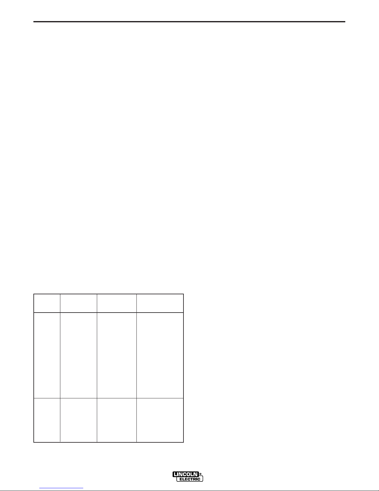
35 volts at the welder current rating. The table gives a
summary of CV outputs when the Adapter is connected.
NOTE: WHEN ENGINE WELDER IS SUPPLIED
WITH A METER, THE AMMETER DOES NOT WORK
WHEN WELDING IN THE CV MODE.
The CV Adapter will fit any of the following engine
welders:
• SA-200 with electronic idler and FDW DC exciter
(above Code 7240)
• Classic I and II (Below Code 10066)
• SA-250 above Code 7826 and Below code 10066.
• SAE-300 and SAE-400 without Remote Control
option and with 115V FDW DC exciter, 254 alternator exciter, or 214 alternator exciter (above Code
7160) and all SAE-400 WELD’N AIR— NOTE: K-385
CV Adapter below Code 8785 will not operate properly on SAE engine welders above Code 8812.
• SAE-350 — Factory installed only.
• International
350-SA —(Below Code 10066) All machines or factory installed.
450-SAE — Factory installed only.
Estimated time for field installation of the CV Adapter to
welder is 2 to 3 hours.
Rating At 60% 35% Duty
Max. Output At
Machine Duty Cycle Cycle Comments
SA-200 200 amp 250 amp Many procedures
at 35V at 30V limited by
current rating
SA-250 250 amp 310 amp AC auxiliary power
at 35V at 35V is reduced 25%
when in CV mode
SAE-300 300 amp 375 amp Polarity switch
at 35V at 35V is disconnected
SAE-400 & 400 amp 500 amp Polarity switch
SAE-400 at 35V at 35V is disconnected
WELD’N AIR
SAE-350 350 amp 435 amp No polarity switch
at 35V at 35V installed
Inter- AC auxiliary power
national is reduced
350-SA — 310 amp 25% when in CV
at 35V mode
450-SAE — 435 amp No polarity switch
at 35V installed
CV ADAPTER
Page 9

A-2
The CV Adapter consists of a capacitor bank, an electronic control circuit and switches. The capacitors modify the dynamic output characteristics to make the
welder suitable for Innershield welding, and the electronic circuit controls the field current to maintain a
constant voltage output. Two switches are used to
change from CV mode to VV mode. The switches are
interlocked to insure that the capacitors are disconnected before the Adapter can be switched to the VV
mode.
All the components are installed in a control box that
attaches to the welder gas tank rail with an adapter
plate. A control cable is used to connect the CV
Adapter to the welder control circuit and the output terminals. A power cable is used to connect the CV output terminal of the Adapter to the welder negative
brushholder. This connection by-passes the series field
for CV operation. A thermostat assembly is sent with
the Adapter model for the SA-200 and SA-250 to protect the welder if overloaded. Two thermostat assemblies are included, one to be used with the SA-200 and
one to be used with the SA-250. The assembly is field
installed in series with the welder negative brushholder and the power cable. The chance of overloading the
SAE machines is much less so no protection is provided.
GENERAL DESCRIPTION
A-2
The operating schematic is L6922 and the wiring diagrams are M14822 and M14726. The assembly is
shown on G1643.
CV ADAPTER
Page 10
B-1
INSTALLATION
B-1
INSTALLATION
WARNING
HAVE QUALIFIED PERSONNEL DO THE INSTALLATION WORK. TURN THE ENGINE OFF BEFORE
WORKING INSIDE THE MACHINE. IN SOME
CASES IT MAY BE NECESSARY TO REMOVE
SAFETY GUARDS TO PERFORM REQUIRED
INSTALLATION. REMOVE GUARDS ONLY WHEN
NECESSARY AND REPLACE THEM WHEN THE
INSTALLATION REQUIRING THEIR REMOVAL IS
COMPLETE. ALWAYS USE THE GREATEST CARE
WHEN WORKING NEAR MOVING PARTS.
LN-15, LN-22, LN-25 Connection — Instructions cov-
ered under “Operation”.
LN-7 Connection — An LN-7 can be connected to SA250, SAE-300, SAE-350, SAE-400 and SAE-400
WELD’N AIR engine welders that have AC auxiliary
power by using a K240 Contactor Kit. Connect the contactor kit to the engine welder and LN-7 per S17525 or
S15416 connection diagram that is sent with the K240
Contactor Kit. The engine welder 115 volt receptacle
will supply the AC power that is needed. Place the
welder idler control in the high position before welding.
When the LN-7 is connected to an SA-250 or SAE-350,
it will not run at low idle when the idle control is in the
automatic position. The plug connecting the K240
Contactor Kit to the SA-250 or SAE-350 auxiliary
power receptacle must be disconnected to allow the
engine to run at low idle.
2. Set of socket wrenches.
3. 11/32" wrench and 3/8" nut driver or pliers.
4. 1/2" open end wrench and 9/16" wrench.
5. Screwdriver.
6. Electrical insulating tape.
K384 CV ADAPTER TO SA-200 ENGINE
WELDER
NOTE: BEFORE INSTALLING CV ADAPTER, START
ENGINE WELDER AND USE A DC VOLTMETER TO
CHECK THE POLARITY OF THE RED AND BLACK
LEADS CONNECTED TO THE AUXILIARY POWER
RECEPTACLE. THE RED LEAD SHOULD BE NEGATIVE AND THE BLACK LEAD SHOULD BE POSITIVE. IF THE POLARITY IS NOT CORRECT, REFER
TO ENGINE WELDER OPERATING MANUAL FOR
INSTRUCTIONS TO FLASH THE EXCITER TO
OBTAIN THE CORRECT POLARITY.
WARNING
• TURN THE ENGINE OFF WHILE INSTALLING
THIS ACCESSORY.
• KEEP HANDS, HAIR, CLOTHING AND TOOLS
AWAY FROM MOVING PARTS WHEN STARTING
OR OPERATING ENGINE.
CAUTION
ANY SPEED UP OF THE ENGINE RPM BY
CHANGING THE GOVERNOR SETTING OR OVERRIDING THE THROTTLE LINKAGE WILL CAUSE
AN INCREASE IN THE AC AUXILIARY VOLTAGE.
IF THIS VOLTAGE GOES ABOVE 140 VOLTS, THE
LN-7 CONTROL CIRCUIT AND/OR THE CV
ADAPTER CIRCUIT WILL BE DAMAGED! THE
ENGINE GOVERNOR SETTING IS PRESET AT THE
FACTORY — DO NOT ADJUST ABOVE RPM
SPECIFICATIONS LISTED IN ENGINE WELDER
OPERATING MANUAL.
The following tools and materials are recommended for
attaching the CV Adapter to an engine welder:
1. Measuring tape, hammer, center punch and electric
drill with 13/32" drill bit. This is only needed for SA250 engine welders that do not have mounting
holes in fuel tank rail.
CV ADAPTER
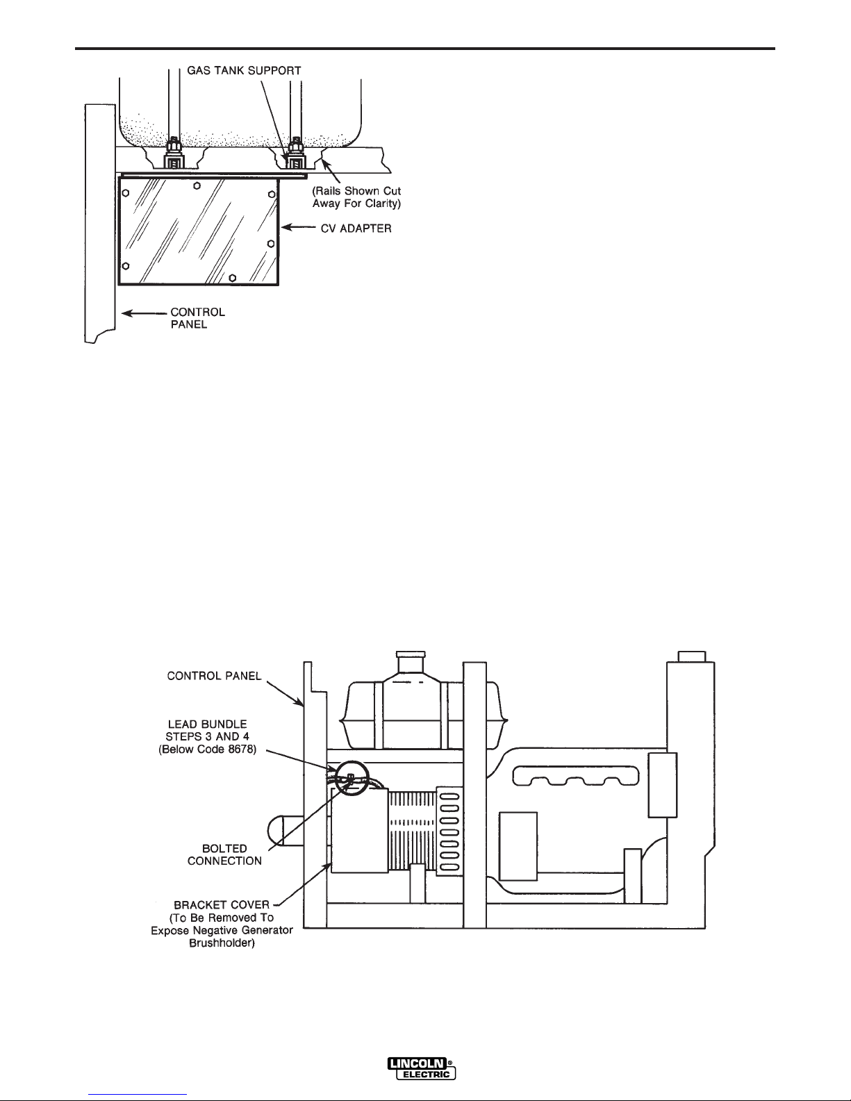
1. Remove roof assembly and bracket cover (cover
on top and at rear of generator). (See Figure 2.)
Also, remove the two gas tank support mounting
bolts on the side opposite the output studs.
2. Mount CV Adapter (nameplate should have an
“SA” above the code number) to the gas tank support holes. Use one 3/8" bolt with hardware
removed in Step 1 and one stud on Adapter. One
3/8" bolt will not be used as a 3/8" stud from the
Adapter case replaces it. In mounting the unit, be
sure the fuel line and choke cable are not pinched.
(See Figure 1.)
NOTE: FOR STEPS 3 THROUGH 10, REFER TO
S17514 OR S17515 CONNECTION DIAGRAMS FOR
THE APPROPRIATE WELDER CODE NUMBER. CV
ADAPTER CONTROL LEADS ARE NOT COLOR
CODED ON ALL UNITS.
Page 11
B-2
INSTALLATION
4. FOR CODE NUMBERS BELOW 8678, connect
CV Adapter lead 610 to black exciter lead bolted
connection shown in Figure 2 and insulate the connection with tape. Tape unused lead terminal on
lead 610.
FOR CODE NUMBERS ABOVE 8678, tape up ring
terminal on CV Adapter lead 610 and connect
push-on terminal of CV Adapter lead 610 to black
exciter lead on idler control P.C. board that was
connected to brown field lead.
5. Remove existing blue field lead from the center terminal of the Fine Current Adjustment rheostat and
connect it to CV Adapter lead 503 using #10 X 1/4
screw and nut provided. Insulate connection with
tape.
B-2
FIGURE 1 – CV Adapter Mounting.
3. FOR CODE NUMBERS BELOW 8678, unbolt
existing brown field lead from black exciter leads in
the lead bundle and bolt it to CV Adapter lead 509
using #10 x 1/4 bolt and nut provided. Tape up connection and unused lead terminal on lead 509 (see
Figure 2 below).
FOR CODE NUMBERS ABOVE 8678, remove
existing brown field lead from black exciter lead on
the idler control P.C. board and connect the brown
field lead to CV Adapter lead 509 using the existing push-on terminal. Tape up connection and
unused ring terminal.
6. Connect CV Adapter lead 602 to the center terminal of the Fine Current Adjustment rheostat.
Connect CV Adapter lead 600 to the end terminal
of the Fine Current Adjustment rheostat that has
an existing lead connected to it.
7. Connect CV Adapter leads “Neg” and “Pos” to the
back of the SA-200 negative and positive output
terminals respectively. Tape these leads to generator lead bundle for support.
FIGURE 2 – SA-200 with Roof Assembly Removed.
CV ADAPTER
Page 12
B-3
INSTALLATION
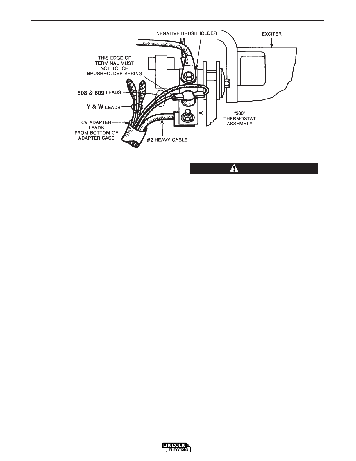
FIGURE 3 – View of Negative Generator Brushholder after Bracket Cover is Removed.
B-3
NOTE: FOR STEPS 8 THROUGH 10, REFER TO
FIGURE 3.
8. The negative generator brushholder, exposed
when bracket cover (see Figure 2) is removed, is
at the 11 o’clock position when the commutator is
viewed from the control panel end of welder.
Remove the 5/16 bolt which connects the two
existing cables to the negative brushholder. Locate
the thermostat assembly marked “200” and reconnect the two cables to the negative brushholder
with one end of the thermostat assembly bolted
between the cable lugs and the brushholder.
9. Route the CV Adapter leads, which exit from the
bottom of the Adapter case, through a 1-1/4 x
3-1/2" rectangular opening located at the 5 o’clock
position on the generator frame. Inside the frame,
the leads should be formed against the frame
shell. Use the 5/16-18 x 5/8 bolt with hardware
supplied to connect the #2 heavy cable from the
CV Adapter to the free end of the thermostat
assembly from Step 8. The flat side of the cable lug
should be against the bottom side of the thermostat assembly with the nut washer and lockwasher
on the top.
10. Connect leads 608 and 609, routed into the generator in Step 9, to the two thermostat terminals. Use
tape to separately insulate the unused Y and W
leads. Insure that all leads are well clear of moving
parts and secured in place with tape.
11. Replace the roof assembly and bracket cover
removed in Step 1.
CAUTION
POLARITY OF THE STANDARD OUTPUT TERMINALS MUST BE AS STATED IN STEP 12 AND THE
MAXIMUM OPEN CIRCUIT VOLTAGE WITH THE
LOWER MODE SWITCH IN CV POSITION MUST
BE AS STATED IN STEP 13 BEFORE PLACING
THE UPPER MODE SWITCH IN CV POSITION.
FAILURE TO HAVE THE CORRECT POLARITY
AND VOLTAGE BEFORE PLACING THE UPPER
MODE SWITCH IN CV POSITION WILL RESULT IN
DAMAGE TO THE CV ADAPTER.
12. To check the VV output, place both CV/VV switches on the CV Adapter in the “VV” position. Start the
SA-200 and place idler control in “high” position.
Use a DC voltmeter across the standard output terminals to check the output polarity. If it is incorrect,
recheck Steps 3 through 10. Voltage should be
about 47-60 volts DC when the Fine Current
Adjustment is set at minimum and 87-100 volts DC
when set at maximum. These voltages may be
slightly higher if readings are taken when welder is
cold.
13. To check the CV output, place only the lower
switch in the “CV” position. This may be done while
the engine is running as long as no welding is
being done. Voltage between the positive output
terminal and the CV output terminal should be 7-12
volts DC when the CV Adapter voltage control is at
minimum setting and 36-48 volts DC at maximum
setting.
14. If output varies greatly from that specified in Steps
12 and 13, check wiring and refer to troubleshooting section of manual.
CV ADAPTER
Page 13
B-4
INSTALLATION
B-4
K384 CV ADAPTER TO SA-250 ENGINE
WELDER WITH AC AUXILIARY OUTPUT
WARNING
• TURN THE ENGINE OFF WHILE INSTALLING
THIS ACCESSORY.
• KEEP HANDS, HAIR, CLOTHING AND TOOLS
AWAY FROM MOVING PARTS WHEN STARTING
OR OPERATING ENGINE.
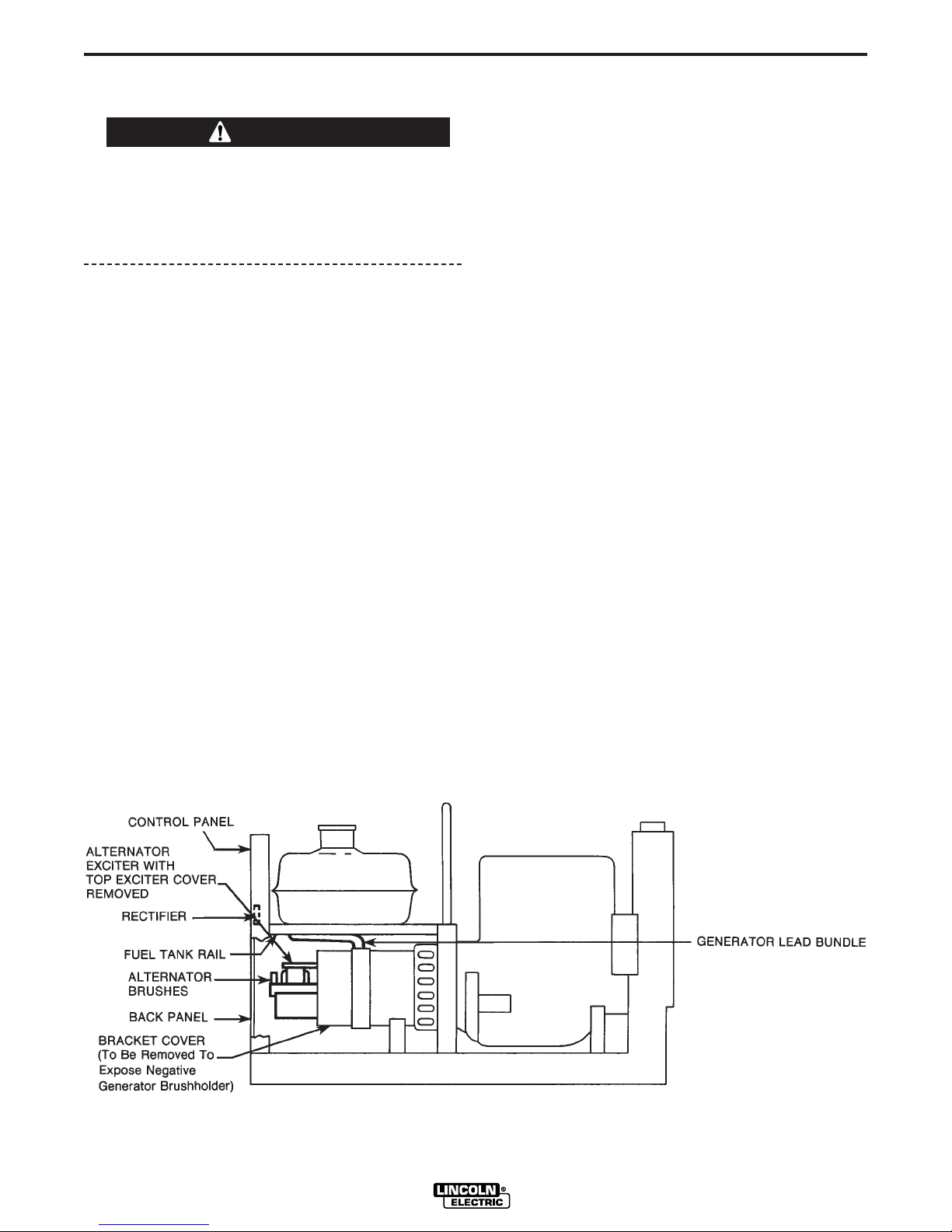
1. Remove roof assembly, back panel, top exciter
cover and bracket cover. See Figure 4.
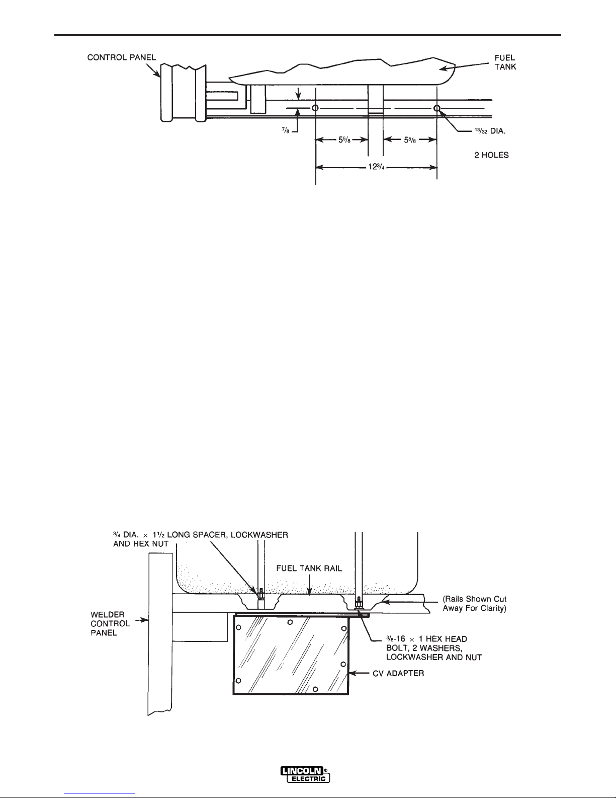
2. Drill two holes in fuel tank rail opposite output terminals as in Figure 2 if holes are not in unit.
3. Mount CV Adapter (unit with “SA” above code
number) to the support holes. Use the one stud on
the Adapter case, a spacer, lockwasher, and nut on
one end and 3/8-16 x 1 hex head bolt and hardware on the other end as shown in Figure 6. In
mounting the unit, be sure the fuel line and choke
cable are not pinched.
NOTE: FOR STEPS 4 THROUGH 12, REFER TO
S17517 CONNECTION DIAGRAM FOR UNITS
WITHOUT REMOTE CONTROL AND S17766 FOR
UNITS WITH REMOTE CONTROL. CV ADAPTER
CONTROL LEADS ARE NOT COLOR CODED ON
ALL UNITS.
5. Tape up ring terminal on CV Adapter lead 610 and
connect push-on terminal of CV Adapter lead 610
to black lead on positive terminal of rectifier.
6. Remove existing field lead from the center terminal
of the Fine Current Adjustment rheostat and connect it to the CV Adapter lead 503 using #10-24 x
1/4 screw and nut provided. Insulate the connection with tape. For units with remote control, leave
blue lead from remote switch in place on center
terminal of rheostat.
7. Connect CV Adapter lead 602 to the center terminal of the Fine Current Adjustment Rheostat.
For units without remote control — connect CV
Adapter lead 600 to the end terminal of the Fine
Current Adjustment Rheostat that has an existing
lead connected to it.
For units with remote control — remove remote
switch from panel to connect CV Adapter lead 600
to the remote switch terminal that has a yellow and
a black lead connected to it. Replace remote
switch on panel.
8. Connect CV Adapter leads “Neg” and “Pos” to the
back of the negative and positive output terminals
respectively. Tape these leads to generator lead
bundle for support.
4. Remove existing brown field lead from the black
lead on the positive rectifier terminal and connect
the brown field lead to CV Adapter lead 509 using
the existing push-on terminal. Tape up connection
and unused ring terminal. Rectifier located on back
of control panel. See Figure 4.
FIGURE 4 – SA-250 with Roof Assembly Removed.
CV ADAPTER
Page 14
B-5
INSTALLATION
FIGURE 5 – Fuel Tank as Viewed from Top.
B-5
NOTE: FOR STEPS 9 THROUGH 12, REFER TO
FIGURES 4 AND 7.
9. The negative generator brushholder, exposed
when bracket cover (see Figure 4) is removed, is
at the 11 o’clock position when the commutator is
viewed from the control panel end of welder.
Remove the 5/16 bolt which connects the two
existing cables to the negative brushholder. Obtain
the thermostat assembly marked “250” and reconnect the two cables to the negative brushholder
with one end of the thermostat assembly bolts
between the cable lugs and the brushholder.
10. Route the CV Adapter leads, which exit from the
bottom of the Adapter case, through a 1-1/4 X
3-1/2" rectangular opening located at the 5 o’clock
position on the generator frame. Inside the frame,
the leads should be formed against the frame
shell. Use the 5/16-18 x 5/8 bolt with hardware
supplied to connect the #2 heavy cable from the
CV Adapter to the free end of the thermostat
assembly from Step 9. The flat side of the cable lug
should be against the bottom side of the thermostat assembly with the nut, washer and lockwasher on the top.
11. Connect leads 608 and 609, routed into the generator in Step 10, to the two thermostat terminals.
12. Disconnect the white and yellow leads connected
to the alternator brushes and reconnect the brush
leads as before. Re-route these white and yellow
leads over the top of the generator brushholder to
meet the W and Y leads of the CV Adapter from
Step 10. Connect W lead to white lead and Y lead
to yellow lead using #10 x 1/4 screw and nut provided. Insulate each connection with tape. Insure
that all leads are well clear of moving parts and
secured in place with tape.
13. Replace roof assembly, back panel, top exciter
cover and bracket cover removed in Step 1.
FIGURE 6 – CV Adapter Mounting (Side View).
CV ADAPTER
Page 15

B-6
INSTALLATION
FIGURE 7 – View of Negative Generator Brushholder after Bracket Cover is Removed.
B-6
CAUTION
POLARITY OF THE STANDARD OUTPUT TERMINALS MUST BE AS STATED IN STEP 14 AND THE
MAXIMUM OPEN CIRCUIT VOLTAGE WITH THE
LOWER MODE SWITCH IN CV POSITION MUST
BE AS STATED IN STEP 15 BEFORE PLACING
THE UPPER MODE SWITCH IN CV POSITION.
FAILURE TO HAVE THE CORRECT POLARITY
AND VOLTAGE BEFORE PLACING THE UPPER
MODE SWITCH IN CV POSITION WILL RESULT IN
DAMAGE TO THE CV ADAPTER.
14. To check the VV output, place both CV/VV switches on the CV Adapter in the “VV” position. If welder
has remote control, set remote control switch to
local position. Start the SA-250 and place idler
control in “high” position. Use a DC voltmeter
across the standard output terminals to check the
output polarity. If it is incorrect, recheck Steps 4
through 12. Open circuit voltage should be about
43-53 volts DC when the Fine Current Adjustment
is set to minimum and 93-100 volts DC when set at
maximum. These voltages may be higher if readings are taken when welder is cold.
16. If output varies greatly from that specified in Steps 14
and 15, check wiring. If this does not solve problem,
refer to Troubleshooting Section of manual.
K384 CV ADAPTER TO SA-250 ENGINE
WELDER WITH DC AUXILIARY OUTPUT
NOTE: Before installing CV Adapter, start engine welder
and use a DC voltmeter to check the polarity of the red
and black leads connected to the auxiliary power receptacle. The red lead should be negative and the black lead
should be positive. If the polarity is not correct, refer to
engine welder operating manual for instructions to flash
the exciter to obtain the correct polarity.
WARNING
• TURN THE ENGINE OFF WHILE INSTALLING THIS
ACCESSORY.
• KEEP HANDS, HAIR, CLOTHING AND TOOLS
AWAY FROM MOVING PARTS WHEN STARTING
OR OPERATING ENGINE.
1. Remove roof assembly and bracket cover (cover on
top and at rear of generator).
15. To check the CV output, place only the lower
switch in the “CV” position. This may be done while
the engine is running as long as no welding is
being done. Voltage between the positive output
terminal and the CV output terminal should be 7-12
volts when the CV Adapter voltage control is at
minimum setting and 36-48 volts at maximum setting.
2. Drill two holes in fuel tank rail opposite output terminals as in Figure 8, if holes are not in unit.
3. Mount CV Adapter (unit with “SA” above code number) to the support holes. Use the one stud on the
Adapter case, a spacer, lockwasher, and nut on one
end and 3/8-16 x 1 hex head bolt and hardware on
the other end as shown in Figure 9. In mounting the
unit, be sure the fuel line and choke cable are not
pinched.
CV ADAPTER
Page 16

B-7
INSTALLATION
FIGURE 8 – Fuel Tank as Viewed from Top.
B-7
NOTE: FOR STEPS 4 THROUGH 11, REFER TO
S17516 CONNECTION DIAGRAM FOR UNITS WITHOUT REMOTE CONTROL AND S17765 FOR UNITS
WITH REMOTE CONTROL. CV ADAPTER CONTROL LEADS ARE NOT COLOR CODED ON ALL
UNITS.
4. Unbolt existing brown field lead from black exciter
leads in the lead bundle and bolt it to CV Adapter
lead 509 using # 10 x 1/4 bolt and nut provided.
Tape up connection and unused lead terminal on
lead 509 (see Figure 10).
5. Connect CV Adapter lead 610 to black exciter lead
bolted connection shown in Figure 10 and insulate
the connection with tape. Tape unused lead terminal on lead 610.
6. Remove existing blue field lead from the center terminal of the Fine Current Adjustment rheostat and
connect it to CV Adapter lead 503 using #10 x 1/4
screw and nut provided. Insulate connection with
tape. For units with remote control, leave blue lead
from remote switch in place on center terminal of
rheostat.
7. Connect CV Adapter lead 602 to the center terminal of the Fine Current Adjustment rheostat.
For units without remote control — connect CV
Adapter lead 600 to the end terminal of the Fine
Current Adjustment rheostat that has an existing
lead connected to it.
For units with remote control — remove remote
switch from panel to connect CV Adapter lead 600
to the remote switch terminal that has a yellow and
a black lead connected to it. Replace remote
switch on panel.
FIGURE 9 – CV Adapter Mounting (Side View).
CV ADAPTER
Page 17

B-8
FIGURE 10 – SA-250 with Roof Assembly Removed.
8. Connect CV Adapter leads “Neg” and “Pos” to the
back of the SA-250 negative and positive output
terminals respectively. Tape these leads to generator lead bundle for support.
NOTE: FOR STEPS 9 THROUGH 11, REFER TO FIGURES 10 AND 11.
INSTALLATION
B-8
9. The negative generator brushholder, exposed
when bracket cover (see Figure 10) is removed, is
at the 11 o’clock position when the commutator is
viewed from the control panel end of welder.
Remove the 5/16 bolt which connects the two
existing cables to the negative brushholder. Locate
the thermostat assembly marked “250” and reconnect the two cables to the negative brushholder
with one end of the thermostat assembly bolted
between the cable lugs and the brushholder.
FIGURE 11 – View of Negative Generator Brushholder after Bracket Cover is Removed.
CV ADAPTER
Page 18

B-9
INSTALLATION
B-9
10. Route the CV Adapter leads, which exit from the
bottom of the Adapter case, through a 1-1/4 x 31/2" rectangular opening located at the 5 o’clock
position on the generator frame. Inside the frame,
the leads should be formed against the frame
shell. Use the 5/16-18 x 5/8 bolt with hardware
supplied to connect the #2 heavy cable from the
CV Adapter to the free end of the thermostat
assembly from Step 9. The flat side of the cable lug
should be against the bottom side of the thermostat assembly with the nut, washer and lockwasher on the top.
11. Connect leads 608 and 609, routed into the generator in Step 10, to the two thermostat terminals.
Use tape to separately insulate the unused Y and
W leads. Insure that all leads are well clear of moving parts and secured in place with tape.
12. Replace the roof assembly and bracket cover
removed in Step 1.
CAUTION
POLARITY OF THE STANDARD OUTPUT TERMINALS MUST BE AS STATED IN STEP 13 AND THE
MAXIMUM OPEN CIRCUIT VOLTAGE WITH THE
LOWER MODE SWITCH IN CV POSITION MUST BE
AS STATED IN STEP 14 BEFORE PLACING THE
UPPER MODE SWITCH IN CV POSITION. FAILURE
TO HAVE THE CORRECT POLARITY AND VOLTAGE BEFORE PLACING THE UPPER MODE
SWITCH IN CV POSITION WILL RESULT IN DAMAGE TO THE CV ADAPTER.
13. To check the VV output, place both CV/VV switches on the CV Adapter in the “VV” position. If welder
has remote control, set remote control switch to
local position. Start the SA-250 and place idler
control in “high” position. Use a DC voltmeter
across the standard output terminals to check the
output polarity. If it is incorrect, recheck Steps 3
through 10. Voltage should be about 47-60 volts
DC when the Fine Current Adjustment is set at
minimum and 87-100 volts DC when set at maximum. These voltages may be slightly high if readings are taken when welder is cold.
14. To check the CV output, place only the lower
switch in the “CV” position. This may be done while
the engine is running as long as no welding is
being done. Voltage between the positive output
terminal and the CV output terminal should be 7-12
volts DC when the CV Adapter voltage control is at
minimum setting and 36-48 volts DC at maximum
setting.
15. If output varies greatly from that specified in Steps
13 and 14, check wiring and refer to troubleshooting section of manual.
K384 CV ADAPTER TO CLASSIC I ENGINE
WELDER
NOTE: BEFORE INSTALLING CV ADAPTER, START
ENGINE WELDER AND USE A DC VOLTMETER TO
CHECK THE POLARITY OF THE RED AND BLACK
LEADS CONNECTED TO THE AUXILIARY POWER
RECEPTACLE. THE RED LEAD SHOULD BE NEGATIVE AND THE BLACK LEAD SHOULD BE POSITIVE. IF THE POLARITY IS NOT CORRECT, REFER
TO ENGINE WELDER OPERATING MANUAL FOR
INSTRUCTIONS TO FLASH THE EXCITER TO
OBTAIN THE CORRECT POLARITY.
WARNING
• TURN THE ENGINE OFF WHILE INSTALLING
THIS ACCESSORY.
• KEEP HANDS, HAIR, CLOTHING AND TOOLS
AWAY FROM MOVING PARTS WHEN STARTING
OR OPERATING ENGINE.
1. Remove roof assembly and bracket cover (cover
on top and at rear of generator). (See Figure 2.)
Also, remove the two gas tank support mounting
bolts on the side opposite the output studs.
2. Mount CV Adapter (nameplate should have an
“SA” above the code number) to the gas tank support holes. Use one 3/8" bolt with hardware
removed in Step 1 and one stud on Adapter. One
3/8" bolt will not be used as a 3/8" stud from the
Adapter case replaces it. In mounting the unit, be
sure the fuel line and choke cable are not pinched.
(See Figure 1.)
NOTE: FOR STEPS 3 THROUGH 10, REFER TO
L8684 OR L8984 CONNECTION DIAGRAMS FOR
THE APPROPRIATE WELDER CODE NUMBER. CV
ADAPTER CONTROL LEADS ARE NOT COLOR
CODED ON ALL UNITS.
3. Remove existing brown field lead from black
exciter lead on the idler control P.C. board and
connect the brown field lead to CV Adapter lead
509 using the existing push-on terminal. Tape up
connection and unused ring terminal.
4. Tape up ring terminal on CV Adapter lead 610 and
connect push-on terminal of CV Adapter lead 610
to black exciter lead on idler control P.C. board that
was connected to brown field lead.
CV ADAPTER
Page 19

B-10
INSTALLATION
B-10
5. Remove existing blue field lead from the center terminal of the Fine Current Adjustment rheostat and
connect it to CV Adapter lead 503 using #10 X 1/4
screw and nut provided. Insulate connection with
tape.
6. Connect CV Adapter lead 602 to #602 on the terminal strip. Connect CV Adapter lead 600 to #600
on the terminal strip. If there are leads already present at 600 and 602 on the terminal strip, the leads
remain there.
NOTE: A TERMINAL STRIP, LOCATED NEAR THE
OUTPUT RECEPTACLE, IS PROVIDED TO SIMPLIFY THE INSTALLATION.
7. Connect CV Adapter leads “Neg” and “Pos” to the
back of the Classic I negative and positive output
terminals respectively. Tape these leads to generator lead bundle for support.
NOTE: FOR STEPS 8 THROUGH 10, REFER TO
FIGURE 3.
8. The negative generator brushholder, exposed
when bracket cover (see Figure 2) is removed, is
at the 11 o’clock position when the commutator is
viewed from the control panel end of welder.
Remove the 5/16 bolt which connects the two
existing cables to the negative brushholder. Locate
the thermostat assembly marked “200” and reconnect the two cables to the negative brushholder
with one end of the thermostat assembly bolted
between the cable lugs and the brushholder.
CAUTION
POLARITY OF THE STANDARD OUTPUT TERMINALS MUST BE AS STATED IN STEP 12 AND THE
MAXIMUM OPEN CIRCUIT VOLTAGE WITH THE
LOWER MODE SWITCH IN CV POSITION MUST BE
AS STATED IN STEP 13 BEFORE PLACING THE
UPPER MODE SWITCH IN CV POSITION. FAILURE
TO HAVE THE CORRECT POLARITY AND VOLTAGE BEFORE PLACING THE UPPER MODE
SWITCH IN CV POSITION WILL RESULT IN DAMAGE TO THE CV ADAPTER.
12. To check the VV output, place both CV/VV switches on the CV Adapter in the “VV” position. Start the
Classic I and place idler control in “high” position.
Use a DC voltmeter across the standard output terminals to check the output polarity. If it is incorrect,
recheck Steps 3 through 10. Voltage should be
about 47-60 volts DC when the Fine Current
Adjustment is set at minimum and 87-100 volts DC
when set at maximum. These voltages may be
slightly higher if readings are taken when welder is
cold.
13. To check the CV output, place only the lower
switch in the “CV” position. This may be done while
the engine is running as long as no welding is
being done. Voltage between the positive output
terminal and the CV output terminal should be 7-12
volts DC when the CV Adapter voltage control is at
minimum setting and 36-48 volts DC at maximum
setting.
9. Route the CV Adapter leads, which exit from the
bottom of the Adapter case, through a 1-1/4 x
3-1/2" rectangular opening located at the 5 o’clock
position on the generator frame. Inside the frame,
the leads should be formed against the frame
shell. Use the 5/16-18 x 5/8 bolt with hardware
supplied to connect the #2 heavy cable from the
CV Adapter to the free end of the thermostat
assembly from Step 8. The flat side of the cable lug
should be against the bottom side of the thermostat assembly with the nut washer and lockwasher
on the top.
10. Connect leads 608 and 609, routed into the generator in Step 9, to the two thermostat terminals. Use
tape to separately insulate the unused Y and W
leads. Insure that all leads are well clear of moving
parts and secured in place with tape.
11. Replace the roof assembly and bracket cover
removed in Step 1.
CV ADAPTER
14. If output varies greatly from that specified in Steps
12 and 13, check wiring and refer to troubleshooting section of manual.
Page 20

B-11
INSTALLATION
B-11
K384 CV ADAPTER TO CLASSIC II
ENGINE WELDER
WARNING
• TURN THE ENGINE OFF WHILE INSTALLING
THIS ACCESSORY.
• KEEP HANDS, HAIR, CLOTHING AND TOOLS
AWAY FROM MOVING PARTS WHEN STARTING
OR OPERATING ENGINE.
1. Remove roof assembly, back panel, top exciter
cover and bracket cover. See Figure 11A.
2. Mount CV Adapter (unit with “SA” above code
number) to the support holes. Use the one stud on
the Adapter case, a spacer, lockwasher, and nut on
one end and 3/8-16 x 1 hex head bolt and hardware on the other end as shown in Figure 6. In
mounting the unit, be sure the fuel line and choke
cable are not pinched.
NOTE: FOR STEPS 3 THROUGH 11, REFER TO
L8594 OR L9071 CONNECTION DIAGRAMS.
3. Remove existing brown field lead from the black
lead on the positive rectifier terminal and connect
the brown field lead to CV Adapter lead 509 using
the existing push-on terminal. Tape up connection
and unused ring terminal. Rectifier located on back
of control panel. See Figure 11A.
5. Remove existing field lead from the center terminal
of the Fine Current Adjustment rheostat and connect it to the CV Adapter lead 503 using #10-24 x
1/4 screw and nut provided. Insulate the connection with tape. For units with remote control, leave
blue lead from remote switch in place on center
terminal of rheostat.
6. Connect CV Adapter lead 602 to #602 on the terminal strip. Also connect the CV Adapter lead 600
to #600 on terminal strip. If there are leads already
present at 600 and 602 on the terminal strip, the
leads remain there. See Figure 11A for terminal
strip location.
7. Connect CV Adapter leads “Neg” and “Pos” to the
back of the negative and positive output terminals
respectively. Tape these leads to generator lead
bundle for support.
NOTE: FOR STEPS 8 THROUGH 11, REFER TO FIGURES 7 AND 11A.
8. The negative generator brushholder, exposed
when bracket cover (see Figure 11A) is removed,
is at the 11 o’clock position when the commutator
is viewed from the control panel end of welder.
Remove the 5/16 bolt which connects the two
existing cables to the negative brushholder. Obtain
the thermostat assembly marked “250” and reconnect the two cables to the negative brushholder
with one end of the thermostat assembly bolts
between the cable lugs and the brushholder.
4. Tape up ring terminal on CV Adapter lead 610 and
connect push-on terminal of CV Adapter lead 610
to black lead on positive terminal of rectifier.
FIGURE 11A
CV ADAPTER
Page 21

B-12
INSTALLATION
B-12
9. Route the CV Adapter leads, which exit from the
bottom of the Adapter case, through a 1-1/4 X 31/2" rectangular opening located at the 5 o’clock
position on the generator frame. Inside the frame,
the leads should be formed against the frame
shell. Use the 5/16-18 x 5/8 bolt with hardware
supplied to connect the #2 heavy cable from the
CV Adapter to the free end of the thermostat
assembly from Step 8. The flat side of the cable lug
should be against the bottom side of the thermostat assembly with the nut, washer and lockwasher on the top.
10. Connect leads 608 and 609, routed into the generator in Step 9, to the two thermostat terminals.
11. Disconnect the white and yellow leads connected
to the alternator brushes and reconnect the brush
leads as before. Re-route these white and yellow
leads over the top of the generator brushholder to
meet the W and Y leads of the CV Adapter from
Step 9. Connect W lead to white lead and Y lead to
yellow lead using #10 x 1/4 screw and nut provided. Insulate each connection with tape. Insure that
all leads are well clear of moving parts and
secured in place with tape.
12. Replace the roof assembly and bracket cover
removed in Step 1.
14. To check the CV output, place only the lower
switch in the “CV” position. This may be done while
the engine is running as long as no welding is
being done. Voltage between the positive output
terminal and the CV output terminal should be 7-12
volts DC when the CV Adapter voltage control is at
minimum setting and 36-48 volts DC at maximum
setting.
15. If output varies greatly from that specified in Steps
13 and 14, check wiring and refer to troubleshooting section of manual.
K385-1 MODEL CV ADAPTER
The K385 has been replaced with the K385-1. The only
difference between them is the mounting bracket. The
K385 was used on SAE-300 and SAE-400 Amp Engine
Welder with AC Auxiliary power between codes 8813
and 9782. The K385-1 has a universal mounting bracket which permits it to be mounted on codes between
8813 and 9782, as well as all codes above 9782
including the SAE-400 WELD’N AIR.
The Figures A and B show the mounting bracket in different positions, depending on the type of fuel tank rail
being used.
CAUTION
POLARITY OF THE STANDARD OUTPUT TERMINALS MUST BE AS STATED IN STEP 13 AND THE
MAXIMUM OPEN CIRCUIT VOLTAGE WITH THE
LOWER MODE SWITCH IN CV POSITION MUST BE
AS STATED IN STEP 14 BEFORE PLACING THE
UPPER MODE SWITCH IN CV POSITION. FAILURE
TO HAVE THE CORRECT POLARITY AND VOLTAGE BEFORE PLACING THE UPPER MODE
SWITCH IN CV POSITION WILL RESULT IN DAMAGE TO THE CV ADAPTER.
13. To check the VV output, place both CV/VV switches on the CV Adapter in the “VV” position. If welder
has remote control, set remote control switch to
local position. Start the Classic II and place idler
control in “high” position. Use a DC voltmeter
across the standard output terminals to check the
output polarity. If it is incorrect, recheck Steps 3
through 11. Voltage should be about 47-60 volts
DC when the Fine Current Adjustment is set at
minimum and 87-100 volts DC when set at maximum. These voltages may be slightly high if readings are taken when welder is cold.
FIGURE A
FIGURE B
CV ADAPTER
Page 22

B-13
FIGURE 12 – Engine Welder (Left Side).
INSTALLATION
K385-1 CV ADAPTER TO SAE-300, SAE-400 OR
SAE-400 WELD’N AIR ENGINE WELDER
NOTE: BEFORE INSTALLING CV ADAPTER ON ENGINE
WELDERS WITH DC AUXILIARY POWER, START ENGINE
WELDER AND USE A DC VOLTMETER TO CHECK THE POLARITY OF THE RED AND BLACK LEADS CONNECTED TO THE
AUXILIARY POWER RECEPTACLE. THE RED LEAD SHOULD
BE NEGATIVE AND THE BLACK LEAD SHOULD BE POSITIVE.
IF THE POLARITY IS NOT CORRECT, REFER TO ENGINE
WELDER OPERATING MANUAL FOR INSTRUCTIONS TO
FLASH THE EXCITER TO OBTAIN THE CORRECT POLARITY.
Only use K385-1 CV Adapter that has a code number
above 8785 on SAE-300, SAE-400 and SAE-400
WELD’N AIR engine welders with AC auxiliary power
and Code Number above 8812.
NOTE: FOR STEPS 3 THROUGH 13, REFER TO THE
PROPER CONNECTION DIAGRAM IN THIS MANUAL FOR THE WELDER WITH THE APPROPRIATE
TYPE OF AUXILIARY POWER AND CODE NUMBER.
CV ADAPTER CONTROL LEADS ARE NOT COLOR
CODED ON ALL UNITS.
3. Remove existing yellow lead from the outside ter-
4. Remove existing blue resistor lead from reversing
WARNING
• TURN THE ENGINE OFF WHILE INSTALLING
THIS ACCESSORY.
• KEEP HANDS, HAIR, CLOTHING AND TOOLS
AWAY FROM MOVING PARTS WHEN STARTING
OR OPERATING ENGINE.
-----------------------------------------------------------------------
1. Remove the upper bracket cover or the wrap-
around bracket cover on older welders with AC
auxiliary power. Also, remove the two fuel tank
support mounting bolts on the side opposite the
output terminals. See Figure 12. On the SAE-400
(with codes 10601, 10856 and 10884) and all
WELD’N AIR, remove the guards mounted on the
inside of the front control panel.
2. Mount the K385-1 loosely in position as shown in
Figure B and Figure 13 for SAE-400 (Codes 9783
and above) or loosely in position as shown in
Figure A and Figure 13 for SAE-400 WELD’N AIR.
It is important that the CV Adapter be positioned
flush against the fuel tank rail. Take care not to
pinch any leads or lines.
5. Remove existing blue field lead from its connection
6.
•
• (For SAE 400 and WELD N’ AIR with codes
10601, 10602, 10856, 10884 and 10885) Remove
the existing brown field lead from the 500Ω resister
and connect it to the CV Adapter lead 509 using the
#10-1/4 screw and nut that is provided. Insulate the
connection with tape.
B-13
minal of the reversing switch and connect it to the
same terminal on the reversing switch that is connected to the red lead (a green lead may also be
on this terminal).
switch and connect both ends of this blue lead to
the same resistor terminal to store lead.
point and connect it to CV Adapter lead 503 using
#10 x 1/4 screw and nut provided. Insulate connection with tape.
(For codes 8812 through 10400, 10549 and 10664,
10665)
runs from the generator field) from the center terminal of the Job Selector rheostat, and connect it
to the CV Adapter lead 509 using #10x1/4 screw
and nut provided. Insulate the connection with tape
(requires 115V insulation). On SAE-400 WELD’N
AIR models a second brown lead exists on the Job
Selector rheostat center terminal. This lead runs to
the remote control switch and is to be left in place.
Disconnect existing brown field lead (that
CV ADAPTER
Page 23

B-14
7.
• (For code 8812 through 10400
10664, 10665) Route CV Adapter leads 600, 602,
610, 612 and 613 through plastic lead clamp on
Current Control reactor housing. Connect CV
Adapter lead 602 to the center terminal of the Job
Selector rheostat.
• (For SAE 400 and WELD N’ AIR with codes
10601, 10602, 10856, 10884 AND 10885) Route
the CV Adapter leads 600, 602, 610, 612 and 613
through the plastic lead clamp on the side of the
“Current Control” reactor box. Connect the CV
Adapter leads 600 and 602 to the 500Ω resistor
with the exiting yellow lead.
8.
• (For Code 8812 through 10400
10664) Connect the CV Adapter lead 600 to the
end terminal of the Job Selector rheostat that has
an existing lead connected to it.
• (For SAE 400 and WELD N’ AIR with codes
10362 and 10665) Connect the CV Adapter lead
600 to the resistor terminal with two existing yellow
leads connected to it.
INSTALLATION
FIGURE 13 – Frame Rail Mounting.
, 10549
, 10549
and
and
B-14
9. Connect CV Adapter lead 610 to same terminal on
polarity switch that is connected to existing black
lead.
10.
• (For SAE-300 and -400 welders with DC auxiliary power) Use tape to separately insulate CV
Adapter leads 611, 612 and 613. These leads are
not used.
• (For SAE-300 and -400 welders with AC auxil-
iary power between Codes 7160 and 8812)
Disconnect the flashing diode lead from the flashing contactor solenoid. The flashing diode and the
flashing contactor solenoid are mounted on the
side of the reactor box located behind the control
panel. Connect CV Adapter lead 611 to diode lead
removed from flashing contactor solenoid using
#10 x 1/4 screw and nut provided. Insulate connection with tape. Connect CV Adapter lead 612 to
flashing contactor solenoid terminal that was connected to flashing diode lead. Insulate lead 613
with tape.
FIGURE 14 – View of Negative Generator Brushholder after Bracket cover is Removed.
CV ADAPTER
Page 24

B-15
INSTALLATION
FIGURE 15 –Decal Mounting.
B-15
• (For SAE-300, SAE-400 and SAE-400 WELD’N
AIR welders with AC auxiliary power Code
8812 through 10400
Disconnect the junction in the white lead connected to the flashing diode. The flashing diode is
mounted on the side of the reactor box located
behind the control panel. Connect CV Adapter
lead 611 to one of the white leads that was disconnected and connect CV Adapter lead 612 to
the other white lead. Insulate both connections
with tape. Disconnect reversing switch (switch
used to reverse output stud electrode polarity)
end of green lead connected between reversing
switch and welder frame. Connect this green lead
to CV Adapter lead 613 and tape up connection.
NOTE: ON UNITS BELOW CODE 9936, THE LEAD CONNECTED BETWEEN THE REVERSING SWITCH
reverse output stud electrode polarity)
WELDER FRAME WAS RED.
•
(
For SAE 400 and WELD N’ AIR with codes
10601, 10602 and 10856 Only) Replace lead
#200 that connects the "Diode Bridge" (D1) negative and the control panel ground screw with the
diode lead assembly provided with the K385-1 CV
Adapter. Disconnect the white flashing diode lead
from the white hour meter lead at the taped junction (the flashing diode is mounted on the inside
of the reactor box located behind the control
panel). Connect the CV Adapter leads 611 to the
white flashing diode lead, 612 to the white hour
meter lead, and tape off lead 613. Insulate all
screw connections with tape.
, 10549
and 10664, 10665)
(switch used to
AND
• (For SAE 400 and WELD N’ AIR with codes
10884 and 10885 Only) Disconnect the white
flashing diode lead from the white hour meter
lead at the taped junction (the flashing diode is
mounted on the inside of the reactor box located
behind the control panel). Connect the CV
Adapter leads 611 to the white flashing diode
lead, 612 to the white hour meter lead, and tape
off lead 613. Insulate all screw connections with
tape.
11. Connect CV Adapter lead marked “Neg” to the
back of “Electrode” output terminal. Connect CV
Adapter lead marked “Pos” to the back of “To
Work” output terminal. Tape leads to generator
lead bundle for support.
12. Tape CV Adapter control cable leads to lead bun-
dle to secure control cable.
CV ADAPTER
Page 25

B-16
INSTALLATION
B-16
NOTE: FOR STEPS 13 AND 14 REFER TO FIGURES 12 AND 14.
13. The negative generator brushholder, exposed
when upper bracket cover or wrap-around is
removed (see Figure 12), is at the 11 o’clock position when the commutator is viewed from the control panel end of welder. Remove the 5/16 bolt
which connects the existing cable to the negative
brushholder. Route the #2/0 heavy lead which
exists from the bottom of the CV adapter case as
shown in Figure 14. Obtain a 5/16 X 3/4 bolt from
the hardware sent with the CV Adapter and connect the #2/0 heavy lead which exits from the bottom of the CV Adapter case, along with the cable
removed above, to the negative brushholder. The
#2/0 heavy lead lug should be between the existing cable lug and the brushholder. Tape the #2/0
heavy lead to the battery lead on welders with DC
auxiliary power to support lead. On welders with
AC auxiliary power, tape the #2/0 heavy lead to the
alternator exciter lead bundle coming from the
alternator to support lead where possible.
14. Replace bracket cover removed in Step 1. Also,
tighten the K385-1 CV Adapter which was loosely
mounted in Step 2. For the SAE-400 WELD’N AIR
the CV Adapter must be positioned flush against
the fuel tank rail after tightening.
15. Peel backing from decals sent in mounting kit
package and install as shown in Figure 15. On the
(SAE-400 codes 10601, 10856 and 10884) and all
WELD’N AIR reinstall the two guards that were
removed at step 1. Be sure that the guards have a
clearance of at least one half inch from any electrically live part. All new and existing leads must be
routed so they are clear of any sharp edges on the
guards.
16. To check the VV output, place both CV/VV switch-
es on the CV Adapter in the “VV” position. Set the
Remote Control Switch to the “REMOTE” or
“LOCAL” position as applicable, if so equipped.
Start the engine welder and set for full speed operation. Use a DC voltmeter to check the output
polarity. The “Electrode” output terminal that is
relabeled “Negative” must be negative and the “To
Work” output terminal that is relabeled “Positive”
must be positive. If polarity is not correct, recheck
Steps 3 to 12. Voltage should be about 40-60 volts
DC when the “Job Selector” control is set at minimum and 90-100 volts DC when set at maximum.
These voltages may be higher if readings are
taken when welder is cold.
17. To check the CV output, place only the lower CV
Adapter switch in the CV position. This may be
done while the engine is running as long as no
welding is being done. On codes 10600 and
above the “Job Selector” must be at Maximum
Check voltage between the output stud on the CV
adapter and frame ground. The voltage should be
less than 10 VDC. Voltage between the “To Work”
output terminal that is relabeled “Positive” and the
CV Adapter output terminal should be 7-12 volts
DC when the CV Adapter voltage control is at minimum setting and 36-48 volts DC at maximum setting.
18. If output varies greatly from that specified in Steps
16 and 17, check wiring and refer to the trou
bleshooting section of the manual.
.
CAUTION
POLARITY OF THE STANDARD OUTPUT TERMINALS MUST BE AS
STATED IN STEP 16 AND THE MAXIMUM OPEN CIRCUIT VOLTAGE
WITH THE LOWER MODE SWITCH IN CV POSITION MUST BE AS STATED IN STEP 17 BEFORE PLACING THE UPPER MODE SWITCH IN CV
POSITION. FAILURE TO HAVE THE CORRECT POLARITY AND VOLTAGE BEFORE PLACING THE UPPER MODE SWITCH IN CV POSITION
WILL RESULT IN DAMAGE TO THE CV ADAPTER.
--------------------------------------------------------------------------------------------------
CV ADAPTER
Page 26

C-1
OPERATION
C-1
OPERATION
CAUTION
DO NOT OPERATE SWITCHES ON CV ADAPTER
WHILE WELDING.
VV OR CV WELDING (All Power Sources)
ANY LN-15, LN-22 AND LN-25 WIRE FEEDER OR
WARNING
CABLES ATTACHED TO CV ADAPTER OUTPUT TERMINAL AND STANDARD OUTPUT TERMINALS ARE
ALWAYS ENERGIZED WHEN ENGINE IS RUNNING
REGARDLESS OF MODE SWITCH POSITION. STORE
LN-15, LN-22 AND LN-25 GUN OR ELECTRODE
HOLDER SO THEY DO NOT CONTACT WORK WHEN
NOT WELDING.
VV STICK WELDING (All Power Sources)
Place both mode switches on the CV Adapter to VV Stick
position. For units with remote control, place the Remote
Control Switch in the desired position.
NOTE: THE UPPER SWITCH MUST IN VV POSITION
BEFORE THE LOWER SWITCH CAN BE PLACED IN
VV POSITION. An interlocking handle prevents operation
of the switches in the wrong sequence.
Connect the welding cables to the standard output terminals of the engine welder and use the standard controls to
set the welding current. On the SAE-300, SAE -400 and
SAE-400 WELD’N AIR engine welders, the polarity switch
is disconnected so the standard “To Work” terminal that
has been relabeled “Positive” is always positive, and the
standard “Electrode” terminal that has been relabeled
“Negative” is always negative.
CV INNERSHIELD WELDING
(SA-200, SA-250, Classic I AND Classic II)
Place both mode switches in CV Innershield position.
NOTE: THE LOWER SWITCH MUST BE IN THE CV
POSITION BEFORE THE UPPER SWITCH CAN BE
PLACED IN THE CV POSITION. An interlocking handle
prevents operation of the switches in the wrong
sequence.
For electrode negative Innershield welding, connect the
Wire Feeder to the output terminal on the CV Adapter and
connect the work to the positive standard output terminal.
For electrode positive, reverse the output leads.
(The Wire Feeder electrode lead is then connected to the
positive standard output terminal.)
CV ADAPTER
The negative standard output terminal is not used for CV
welding of either polarity. Set the Wire Feeder polarity
switch to same polarity that is required by electrode.
Connect control lead from the Wire Feeder control box to
work using the spring clip on the end of the lead.
The output voltage is set with the voltage control dial on
the CV Adapter. Set the welder “Current Range Selector”
to the 190-120 position for optimum welding characteristics with Innershield electrodes. Changing the “Current
Range Selector” affects arc characteristics. The setting of
the “Fine Current Adjustment” does not affect the operation in “CV” mode.
When the CV Adapter is in the “CV” mode, the maximum
auxiliary power on SA-250’s and Classic II’s with AC auxiliary power will be reduced by 25%. To obtain maximum
output, place both switches in “VV” position.
If the current rating of the welder is exceeded, a thermostat will reduce the output voltage to about 5 volts. The
thermostat will reset automatically as the machine cools.
If the thermostat trips, lower wire feed speed or duty
cycle.
CV INNERSHIELD WELDING
(SAE Engine Welders)
Place both switches in CV Innershield position.
NOTE: THE LOWER SWITCH MUST BE IN THE “CV”
POSITION BEFORE THE UPPER SWITCH CAN BE
PLACED IN “CV” POSITION. An interlocking handle prevents operation of the switches in the wrong sequence.
For codes 10600 and above, the “Job Selector” Must
be at maximum.
For electrode negative Innershield welding, connect the
electrode lead of a Wire Feeder to the output terminal on
the CV Adapter and connect the work to the “To Work”
standard SAE output terminal that is relabeled “Positive”.
For electrode positive, reverse the output leads. (The
Wire Feeder electrode lead is then connected to the output terminal that is labeled “Positive”.) The standard SAE
“Electrode” output terminal that is relabeled “Negative” is
not used for CV welding of either polarity. Set Wire Feeder
polarity switch to same polarity that is required by electrode. Connect control lead from the Wire Feeder control
box to work using the spring clip on the end of the lead.
The output voltage is set with the voltage control dial on
the CV Adapter. Set the SAE “Current Control” to the 9
o’clock position for optimum welding characteristics with
Innershield electrodes. Changing the “Current Control”
affects arc characteristics.
The setting of the “Job Selector” does not affect operation
in “CV” mode on codes 8812 through 10400 only.
Page 27

D-1
TROUBLESHOOTING
HOW TO USE TROUBLESHOOTING GUIDE
WARNING
Service and Repair should only be performed by Lincoln Electric Factory Trained Personnel.
Unauthorized repairs performed on this equipment may result in danger to the technician
and machine operator and will invalidate your factory warranty. For your safety and to avoid
Electrical Shock, please observe all safety notes and precautions detailed throughout this
manual.
__________________________________________________________________________
This Troubleshooting Guide is provided to
help you locate and repair possible machine
malfunctions. Simply follow the three-step
procedure listed below.
D-1
Step 1. LOCATE PROBLEM (SYMPTOM).
Look under the column labeled “PROBLEM
(SYMPTOMS)”. This column describes possible symptoms that the machine may exhibit. Find the listing that best describes the
symptom that the machine is exhibiting.
Step 2. RECOMMENDED COURSE OF
ACTION
This column provides a course of action for
the Possible Cause.
If you do not understand or are unable to
perform the Recommended Course of Action
safely, contact you local Lincoln Authorized
Field Service Facility.
If for any reason you do not understand the test procedures or are unable to perform the tests/repairs safely, contact your Local
Lincoln Authorized Field Service Facility for technical troubleshooting assistance before you proceed.
CAUTION
CV ADAPTER
Page 28

D-2
TROUBLESHOOTING
Observe all Safety Guidelines detailed throughout this manual
D-2
PROBLEMS
(SYMPTOMS)
1. With CV Adapter in CV position:
a. Open circuit voltage is 60 to
70 volts and cannot be adjusted.
b. Open circuit voltage cannot be
adjusted above 38 volts.
c. Open circuit voltage can be
adjusted to 60-70 volts instead
of the normal maximum 36 to
48 volts.
2. On SA-250, open circuit voltage
remains at 5 to 10 volts and cannot be adjusted.
RECOMMENDED
COURSE OF ACTION
FUNCTION PROBLEMS
A. For Codes below 10400 and 10664 and 10665.
Check to see if DC field circuit is grounded to frame of welder. If grounded, remove
ground. Then check 1/8
(Grounded DC field circuit may or may not cause fuse to blow.) NOTE: On SAE-300,
SAE-400 and SAE-400 WELD’N AIR Engine Welders with AC auxiliary output, disconnect one side of flashing diode. On SAE-300, SAE-400 and SAE-400 WELD’N AIR
machines above Code 8812 or SAE-350 machines also disconnect SAE green lead from
CV Adapter lead 613.
NOTE: ON SAE UNITS BELOW CODE 9936, THE SAE GREEN
LEAD WAS RED.
Reconnect the above items after trouble is determined and resolved.
B. For Codes 10601,10602,10856,10884 and 10885.
Verify that the diodes in the lead between D1 negative and the ground
screw are not shorted and are oriented properly. Check 1/8 amp fuse
on CV adapter PC board and replace if blown.
A. Check to see if DC field circuit is grounded to frame of welder. If
grounded remove ground. Then check if either 5
in CV Adapter box is blown and replace if blown. (Grounded DC field
circuit may or may not cause fuse to blow.) Also check if 2 amp fuse
on CV Adapter PC board is blown and replace if blown.
(1)
amp fuse on CV Adapter PC board and replace if blown.
(1)
amp fuse mounted
3. No CV control of output voltage.
(1)
These fuses are not on earlier units.
A. Lower CV Adapter mode switch in wrong position.
B. On SA-200, SA-250, Classic I and Classic II, thermostat tripped. Wait
for machine to cool down.
C. 2 amp fuse blown on CV Adapter PC board — replace fuse.
D. Output not connected to the proper output terminals. See manual for
proper connections.
E. Defective lower mode switch — replace 3PDT toggle switch (Sl).
F. Defective relay — replace relay.
G.Defective CV Adapter PC board — replace PC board.
CAUTION
If for any reason you do not understand the test procedures or are unable to perform the tests/repairs safely, contact your Local
Lincoln Authorized Field Service Facility for technical troubleshooting assistance before you proceed.
CV ADAPTER
Page 29

D-3
TROUBLESHOOTING
Observe all Safety Guidelines detailed throughout this manual
D-3
PROBLEMS
(SYMPTOMS)
4. No output control when welding
“STICK”.
5. Poor arc characteristics
RECOMMENDED
COURSE OF ACTION
FUNCTION PROBLEMS
A. Lower CV Adapter mode switch in wrong position.
B.
Defective lower CV Adapter mode switch — replace 3PDT toggle switch (Sl).
C. For units with remote control, Remote Control Switch set in the wrong
position.
A. Mode switch in wrong position.
B. Output connected to wrong output terminal.
C. In CV mode — standard current control or range selector in wrong
position. See operating manual.
D. Check bank of capacitors in CV Adapter control box. A failure is indi-
cated if the small vent plug on top of a capacitor is raised or blown out.
Replace entire bank of capacitors. Do not replace individual capacitors.
WARNING
6. Welder does not stay a high
speed while welding.
THE LIQUID ELECTROLYTE IN THESE CAPACITORS IS TOXIC.
AVOID CONTACT WITH ANY PORTION OF YOUR BODY. CLEAN UP
VENTED ELECTROLYTE USING RUBBER GLOVES AND A WATER
DAMPENED CLOTH. ANY ELECTROLYTE WHICH GETS ON SKIN,
CLEAN WITH SOAP AND WATER.
--------------------------------------------------------------------------------------------------
A. Under certain conditions with smooth, spray-type arc transfer, the
idler control may not stay energized. Place idler control in “high” position.
If for any reason you do not understand the test procedures or are unable to perform the tests/repairs safely, contact your Local
Lincoln Authorized Field Service Facility for technical troubleshooting assistance before you proceed.
CAUTION
CV ADAPTER
Page 30

E-1
DIAGRAMS
CONNECTION DIAGRAM — CV ADAPTER TO SA-200
(BELOW CODE 8678)
E-1
S17514
A
CONNECTION DIAGRAM — CV ADAPTER TO SA-200
(ABOVE CODE 8678)
S17515
A
CV ADAPTER
Page 31

E-2
DIAGRAMS
CONNECTION DIAGRAM
CV ADAPTER TO SA-250 WITH AC AUXILIARY POWER
E-2
S17517
A
CONNECTION DIAGRAM
CV ADAPTER TO SA-250 WITH DC AUXILIARY POWER
S17516
A
CV ADAPTER
Page 32

E-3
DIAGRAMS
CONNECTION DIAGRAM — CV ADAPTER TO SA-250 WITH
AC AUXILIARY POWER AND REMOTE CONTROL
E-3
S17766
A
CONNECTION DIAGRAM — CV ADAPTER TO SA-250 WITH
DC AUXILIARY POWER AND REMOTE CONTROL
S17765
A
CV ADAPTER
Page 33

E-4
DIAGRAMS
CONNECTION DIAGRAM — CV ADAPTER TO SAE-300 OR SAE-400 ENGINE WELDER
WITH AC AUXILIARY POWER FOR CODES 7160 TO 8812
E-4
S17519
A
CONNECTION DIAGRAM — CV ADAPTER TO SAE-300 OR SAE-400 ENGINE WELDER
WITH AC AUXILIARY POWER FOR CODES 8812 THROUGH 10400
, 10549
and 10664
S17561
A
CV ADAPTER
Page 34

E-5
DIAGRAMS
CONNECTION DIAGRAM — CV ADAPTER TO SAE-300 OR SAE-400 ENGINE WELDER
WITH DC AUXILIARY POWER
E-5
S17518
A
COLOR CODE
SEE BATTERY
WIRING DIAGRAM
TO LOWER PANEL
GROUND SCREW
TO RECEPTACLES
TO ALTERNATOR
S24465
S
A
CONNECTION DIAGRAM — CV ADAPTER TO SAE-400 AND WELD‘N AIR
WITH CODES 10601, 10602, 10856, 10884 and 10885
B-BLACK
G-GREEN
N-BROWN
R-RED
U-BLUE
W-WHITE
Y-YELLOW
CV ADAPTOR CONTROL LEADS
ARE NOT COLOR CODED
ON ALL UNITS
FLASHING DIODE
AND RESISTOR
GROUND
SCREW
G
TAPE UP LEAD
24465
A
TO NEGATIVE
BRUSH HOLDER
REMOTE CONTROL RECEPTACLE
AND SWITCH
(+)
R
R
POS
+
4
2
500
Y
F
1
R
B
WELD CURRENT
SENSING SWITCH
W
2CR
G
600
41
1
2
42
3
602
4
5
6
P8
REACTOR
X
W
W
SWITCH FOR LOCAL OR
REMOTE CONTROL SHOWN
IN LOCAL POSITION.
POLARITY
SWITCH
B
R
TO WORK TERMINAL
POS.
NEG.
(+)
AC
D2
(-)
AC
NEG
B
-
B
1
3
AC
D1
U
U
ALTERNATOR
ROTOR
+
SLIP
RINGS
W
611
W
W
W
G
612
G
G
G
-
Y
B
R
610
B
AC
(-)
Y
U
N
E
A
2
CV
ADAPTER
600
613
602
503
509
POS.
NEG.
Y
W
U
N
Y
R
PLUG FOR REMOTE CONTROL
POTENTIOMETER
G
RESISTORS
G
CONNECT
TO BASE
REMOTE CONTROL
POTENTIOMETER BOX
1
2
4
BACK VIEW
OF POLARITY
SWITCH
ELECTRODE
G
X
Y
W
U
W
3
CV ADAPTER
Page 35

E-6
DIAGRAMS
E-6
CONNECTION DIAGRAM —
CV ADAPTER TO SAE-400 AND WELD’N AIR ENGINE WELDER Code 10362 AND 10665
COPPER TERMINAL
RECEPTACLE FOR
REMOTE CONTROL
RHEOSTAT
GROUND TERMINAL
WIDE SLOT
S24466
B.01
*
LEAD 613 DOES NOT APPEAR
ON CV ADAPTOR UNITS BELOW 8785
CV ADAPTOR CONTROL LEADS
ARE NOT COLOR CODED
ON ALL UNITS
ELECTRICAL SYMBOLS
PER E1537
LEAD COLOR CODE
B-BLACK
G-GREEN
N-BROWN
TO ENGINE CIRCUIT
W
U
W
G
RESISTORS
G
25
25
25
CB1
R-RED
U-BLUE
W-WHITE
Y-YELLOW
G
CB2
B
G
TO ALTERNATOR
TO ALTERNATOR
R
AC
REMOTE CONTROL
(SWITCH SHOWN IN
LOCAL POSITION)
YBY
FLASHING DIODE
(+)
120
AC
(-)
W
611
612W
610
600
602
509
503
*
R
613
POS.
NEG.
CV ADAPTER
B
W
W
B
Y
Y
U
N
W
N
U
NEGATIVE CV OUTPUT TERMINAL
R
Y
500
N
U
E
A
TO WORK / POSITIVE
CV & VV OUTPUT TERMINAL
+
-
U
F
1
2
TO NEGATIVE BRUSH HOLDER
POLARITY SWITCH
(REVERSING SWITCH)
JOB SELECTOR
RHEOSTAT
ELECTRODE / NEGATIVE
VV OUTPUT TERMINAL
CURRENT CONTROL
REACTOR
CONNECTION DIAGRAM — LN-7 WIRE FEEDER TO ENGINE WELDERS WITH
115 VOLT AC AUXILIARY POWER, CV ADAPTER AND K240 CONTACTOR KIT
S17525
7-15-83
N.A. Connection shown for negative polarity. For positive polarity, reverse cables connected to output terminals.
N.B. 3 conductor #16 power cord physically suitable for the installation and plug rated at 115 volts 15 amperes AC.
N.C. Plug into 115 volt AC receptacle on welder control panel or other 115 volt AC supply rated a minimum of 500 volt amperes.
N.D. Leads #21 and GND. do not appear on LN-7’s with codes below 7026.
N.E. Welding cables must be of proper capacity for the current and duty cycle on immediate and future applications.
N.F. If LN-7 is equipped with a meter kit, extend lead 21 using #14 or larger insulated wire physically suitable for the installation. An
S16586-[ ] remote voltage sensing work lead is available for this purpose. Connect it directly to the work piece keeping it electrically
separate from the welding work lead circuit and connection. For convenience, this extended #21 lead should be taped to the welding
work lead.
N.G. Tape up bolted connection.
CAUTION: Any speed up of the engine RPM by changing the governor setting or over-riding the throttle linkage will cause an increase in
the AC auxiliary voltage. If this voltage goes above 140 volts, the LN-7 control circuit will be damaged. The engine governor setting is pre-set at the factory — do not adjust above RPM specifications listed in engine welder operating manual.
CV ADAPTER
Page 36

E-7
DIAGRAMS
CV ADAPTER WIRING DIAGRAM (FOR SA-200, SA-250, CLASSIC I AND CLASSIC II)
E-7
M14822
A
CV ADAPTER
Page 37

E-8
DIAGRAMS
CV ADAPTER WIRING DIAGRAM (FOR SAE-300, SAE-350, SAE-400 AND 450-SAE)
E-8
M15198
A
CV ADAPTER
Page 38

E-9
DIAGRAMS
CLASSIC I — CONTINENTAL F163 ENGINE
E-9
A
L8684
IDLER
BUTTON
START
CR2 REED RELAY
Y
R
WB B
CONTROL
P.C. BOARD
IDLER
SOLENOID
H
W
BATTERY
AMMETER
W
SWITCH
IGNITION
R
F1
W
N
+-
R
B
15A.
U
-
Y
TO
B
R
E
PLUGS
MAG
N
B
EE
+
OUTPUT
TO EXCITER
IDLER CONTROL
F
610
B
AUX. POWER
SWITCH
Y
ALTERNATOR
12
345
A
UU
N
503
509
600A
RECEPTACLE
N
G
R
H
R
OIL
SWITCH
PRESSURE
Y
EXC
+
41
42
LIGHT
OIL PRESSURE
B
S
R
600
41
600
600A
G
METER
ENGINE HOUR
-
+
B
+
-
U
OUTPUT TERMINAL
POSITIVE CV & VV
POS
NEGATIVE VV
NEG
OUTPUT TERMINAL
602
B
42
602
TERMINAL
41
42
602A
RHEOSTAT
START
MOTOR
GROUND
TO ENGINE
GROUND
TO BASE
STRIP
LEADS
TAPE UP
BRUSH HOLDER
ASSEMBLY
CONNECT TO NEGATIVE
SA-200 THERMOSTAT
Y
W
608
Y
W
CV ADAPTER
ALL UNITS
ARE NOT COLOR CODED ON
CV ADAPTER CONTROL LEADS
R - RED
U - BLUE
LEAD COLOR CODE
B - BLACK
G - GREEN
COPPER
TERMINAL
#2 HEAVY LEAD
609
PLUG FOR
REMOTE CONTROL
COPPER
RESISTORS
REMOTE CONTROL (OPTIONAL)
TERMINAL
AND SWITCH
NEGATIVE CV OUTPUT
Y - YELLOW
W - WHITE
H - BROWN & WHITE
N - BROWN
REMOTE CONTROL PANEL
ELECTRICAL SYMBOLS PER E1537
DRIVEN ARC WELDING POWER SOURCES
Only qualified personnel should install, use, or service
this equipment.
GENERAL MAINTENANCE INSTRUCTIONS FOR ENGINE
WARNING
B
G
W
CONNECT
(WIDE SLOT)
GROUND TERM.
POTENTIOMETER
B
TERMINAL
W
G
41
SEE
Turn the engine OFF before maintenance work unless the
maintenance work requires it to be running.
Keep hands, hair, clothing and tools away from moving parts,
and insure all guards or covers are replaced after servicing.
can injure
MOVING PARTS
-ROTATE THE CURRENT CONTROL TWICE TO CLEAN CONTACTS.
-ELECTRODE AND WORK CONNECTIONS ARE TIGHT.
DAILY CHECKS:
MAINTENANCE INSTRUCTIONS
POTENTIOMETER BOX
REMOTE CONTROL
TO CASE
(WIDE SLOT)
GROUND TERM.
LOCAL OR REMOTE
SWITCH FOR
CONTROL SHOWN IN
LOCAL POSITION.
42
602
600
600 AT THE TERMINAL STRIP. CONNECT THESE LEADS
TO THE CORRESPONDING NUMBERS AT THE TERMINAL STRIP.
*
*
BELOW
LEVEL AND CLEAN.
-ENGINE OIL, COOLANT, AIR CLEANER AND FUEL STRAINER ARE AT PROPER OPERATING
-ALL EQUIPMENT IN SERVICEABLE CONDITION.
AS REQUIRED:
WITH MACHINE NOT RUNNING, REMOVE JUMPER 42 TO
IN THE OPERATING MANUAL.
SEE THE OPERATING MANUAL FOR INSTRUCTIONS.
SEE THE OPERATING MANUAL FOR INSTRUCTIONS.
-GREASE MAY BE ADDED TO BEARINGS NO MORE THAN ONCE A YEAR. SEE INSTRUCTIONS
-REPLACE BRUSHES BEFORE THE PIGTAIL IS WITHIN .25" OF THE COMMUTATOR.
-CLEAN COMMUTATORS OR SLIP RINGS WITH FINE SANDPAPER--NOT EMERY CLOTH.
-BLOW DUST FROM THE MACHINE USING CLEAN LOW PRESSURE AIR.
CV ADAPTER
Page 39

E-10
IDLER
Y
R
WB B
CONTROL
P.C. BOARD
CR2 REED RELAY
R
F1
ONLY.
FUSE IN CIRCUIT
ON C.S.A. VERSION
15A.
DIAGRAMS
E-10
CLASSIC I — CONTINENTAL TM27 ENGINE
L8984
A
COPPER
TERMINAL
12
345
A
F
UU
N
N
503
509
610
B
B
NEGATIVE VV
OUTPUT TERMINAL
600
B
41
42
600
41
600A
OUTPUT TERMINAL
POSITIVE CV & VV
POS
NEG
602
602
STRIP
TERMINAL
42
602A
LEADS
TAPE UP
Y
W
BRUSH HOLDER
CONNECT TO NEGATIVE
ASSEMBLY
THERMOSTAT
609
608
Y
W
#2 HEAVY LEAD
PLUG FOR
COPPER
TERMINAL
RESISTORS
B
(WIDE SLOT)
GROUND TERM.
POTENTIOMETER
REMOTE CONTROL
B
W
G
G
W
CONNECT
TO CASE
(WIDE SLOT)
GROUND TERM.
602
41
600
42
POTENTIOMETER BOX
REMOTE CONTROL
LOCAL OR REMOTE
SWITCH FOR
CONTROL SHOWN IN
LOCAL POSITION.
600 AT THE TERMINAL STRIP. CONNECT THESE LEADS
*
WITH MACHINE NOT RUNNING, REMOVE JUMPER 42 TO
REMOTE CONTROL (OPTIONAL)
600A
AUX. POWER
RECEPTACLE
41
R
B
EE
E
-
+
42
N
CV ADAPTER
TERMINAL
AND SWITCH
REMOTE CONTROL PANEL
SEE
*
BELOW
TO THE CORRESPONDING NUMBERS AT THE TERMINAL STRIP.
W
IDLER
SOLENOID
H
W
BUTTON
BATTERY
AMMETER
START
SWITCH
IGNITION
FUEL SHUT OFF
CARBURETOR
N
+-
U
R
R
B
U
TO EXCITER
Y
TO PLUGS
B
-
+
OUTPUT
SWITCH
IDLER CONTROL
Y
DISTRIBUTOR
COIL
IGNITION
IGNITION
BAT
RESISTOR
G
R
R
G
LIGHT
METER
OIL PRESSURE
ENGINE HOUR
-
+
H
R
OIL
SWITCH
PRESSURE
Y
EXC
+
ALTERNATOR
B
RHEOSTAT
B
S
+
-
R
U
ARE NOT COLOR CODED ON
CV ADAPTER CONTROL LEADS
START
MOTOR
LEAD COLOR CODE
GROUND
TO ENGINE
GROUND
TO BASE
NEGATIVE CV OUTPUT
ALL UNITS
Y - YELLOW
R - RED
U - BLUE
W - WHITE
ELECTRICAL SYMBOLS PER E1537
H - BROWN & WHITE
N - BROWN
B - BLACK
G - GREEN
DRIVEN ARC WELDING POWER SOURCES
GENERAL MAINTENANCE INSTRUCTIONS FOR ENGINE
Turn the engine OFF before maintenance work unless the
maintenance work requires it to be running.
Only qualified personnel should install, use, or service
this equipment.
Keep hands, hair, clothing and tools away from moving parts,
and insure all guards or covers are replaced after servicing.
WARNING
can injure
MOVING PARTS
DAILY CHECKS:
MAINTENANCE INSTRUCTIONS
-ELECTRODE AND WORK CONNECTIONS ARE TIGHT.
LEVEL AND CLEAN.
-ROTATE THE CURRENT CONTROL TWICE TO CLEAN CONTACTS.
-ENGINE OIL, COOLANT, AIR CLEANER AND FUEL STRAINER ARE AT PROPER OPERATING
-ALL EQUIPMENT IN SERVICEABLE CONDITION.
AS REQUIRED:
-GREASE MAY BE ADDED TO BEARINGS NO MORE THAN ONCE A YEAR. SEE INSTRUCTIONS
-REPLACE BRUSHES BEFORE THE PIGTAIL IS WITHIN .25" OF THE COMMUTATOR.
-CLEAN COMMUTATORS OR SLIP RINGS WITH FINE SANDPAPER--NOT EMERY CLOTH.
-BLOW DUST FROM THE MACHINE USING CLEAN LOW PRESSURE AIR.
IN THE OPERATING MANUAL.
SEE THE OPERATING MANUAL FOR INSTRUCTIONS.
SEE THE OPERATING MANUAL FOR INSTRUCTIONS.
CV ADAPTER
Page 40

E-11
D-B+
W
D+
ALTERNATOR
21
DIAGRAMS
CLASSIC II — DEUTZ ENGINE WITH CIRCUIT BREAKERS (CSA)
PIN CONFIGURATION
ON ENGINE
CONNECTOR
8
FUEL
SOLENOID
IDLER
SOLENOID
OIL TEMPERATURE
SENSOR
7
3
4
OIL PRESSURE
SENSOR
5
6
8
4
1
3
2
5
6
7
E-11
L8594
A
59
59A
CR1
BOTTOM VIEW
3
1
53B
TO WELDING
R1
50
SHOWN
58D
()
9
6
B
7
4
A
UURWY
IDLER
P.C.
600
R
610
B
TERMINAL
STRIP
W
-
Y
+
+
GENERATOR
B
+
ALTERNATOR ROTOR
SLIP RINGS
SLIP RING NEAREST
TO IRON
57
BOARD
600
N
AC
AC
R
56
IDLER
ENGINE
PROTECTION
RELAY
58A
60C
58B
+
START
IGNITION
602
W
42
POTENTIOMETER
Y
(SFE-14)
FUSE
SWITCH
SELECTOR
61
60B
60F
58C
56A
60D
602
42
41
41
600A
-
Y
15A.
FUSE
115 VOLT
RECEPTACLE
SWITCH
GNONCS B
60
HOUR METER
ENGINE
SWITCH
602A
R
58
55
54A
54B
53
54
60A
53A
50A
U
ALTERNATOR
AUXILIARY
POWER
WINDINGS
W
CB1
CB2
51A
SI
60E
52
BB
GND
GAUGE
OIL PRESSURE
STARTING
MOTOR
A
N
CURRENT
G
51
A
+
50
+
509
1
N
2
3
WELDER
LEAD BLOCK
N
54
R
CR2 REED
RELAY
U
TRANSFORMER
U
G
230 VOLT
RECEPTACLE
-
503
U
U
VV OUTPUT
TERMINAL
POSITIVE CV &
N
NEGATIVE
POS
NEG
VV OUTPUT
TERMINAL
CB3
CB4
#2 HEAVY LEAD
CONNECT TO NEGATIVE
BRUSH HOLDER
SA-250 THERMOSTAT
ASSEMBLY
TO WELDING
GENERATOR
+
Y
W
609
608
Y
W
NEGATIVE CV OUTPUT TERMINAL
CV ADAPTER
B
COPPER
TERMINAL
PLUG FOR
REMOTE CONTROL
COPPER
TERMINAL
RESISTORS
POTENTIOMETER
GROUND TERM.
(WIDE SLOT)
B
W
W
G
REMOTE CONTROL (OPTIONAL)
REMOTE CONTROL PANEL & SWITCH
41
R-RED
U-BLUE
W-WHITE
LEAD COLOR CODE
B-BLACK
G-GREEN
N-BROWN
ELECTRICAL SYMBOLS PER E1537
G
CONNECT
TO CASE
GROUND TERM.
(WIDE SLOT)
LOCAL OR REMOTE
SWITCH FOR
602
600
42
SEE
BELOW
*
CONTROL PANEL COMPONENTS
SHOWN AS VEIWED FROM REAR.
Y-YELLOW
ALL UNITS
ARE NOT COLOR CODED ON
CV ADAPTER CONTROL LEADS
REMOTE CONTROL
POTENTIOMETER BOX
CONTROL SHOWN IN
LOCAL POSITION.
600 AT THE TERMINAL STRIP. CONNECT THESE LEADS
STRIP.
TO THE CORRESPONDING NUMBERS AT THE TERMINAL
* WITH MACHINE NOT RUNNING, REMOVE JUMPER 42 TO
CV ADAPTER
Page 41

E-12
D-B+
W
D+
ALTERNATOR
21
8
FUEL
SOLENOID
DIAGRAMS
E-12
CLASSIC II — DEUTZ ENGINE
L9071
A
PIN CONFIGURATION
ON ENGINE
IDLER
SOLENOID
OIL TEMPERATURE
SENSOR
7
3
4
OIL PRESSURE
SENSOR
5
6
8
4
1
3
2
5
6
7
CONNECTOR
59
59A
CR1
BOTTOM VIEW
3
1
53B
TO WELDING
R1
50
SHOWN
58D
()
9
6
B
7
4
A
UURWY
IDLER
600
R
610
B
TERMINAL
STRIP
W
-
Y
+
+
GENERATOR
B
+
ALTERNATOR ROTOR
SLIP RINGS
SLIP RING NEAREST
TO IRON
P.C.
600
R
61
57
56A
BOARD
41
N
AC
AC
42
60B
600A
ENGINE
58A
60F
58C
60D
602
41
-
56
IDLER
SWITCH
(SFE-14)
PROTECTION
RELAY
GNONCS B
FUSE
60C
58B
+
HOUR METER
ENGINE
START
IGNITION
SWITCH
602
W
SELECTOR
SWITCH
602A
42
POTENTIOMETER
Y
Y
15A.
FUSE
115 VOLT
RECEPTACLE
60
R
58
55
54A
54B
53
54
60A
53A
50A
U
ALTERNATOR
AUXILIARY
POWER
WINDINGS
W
CB1
(30 AMP)
51A
SI
60E
52
GND
STARTING
BB
G
GAUGE
MOTOR
A
51
OIL PRESSURE
50
1
2
3
WELDER
LEAD BLOCK
54
N
CR2 REED
RELAY
U
CURRENT
TRANSFORMER
U
230 VOLT
RECEPTACLE
+
509
N
N
R
A
+
503
U
U
G
-
POS
NEG
VV OUTPUT
TERMINAL
POSITIVE CV &
N
NEGATIVE
VV OUTPUT
TERMINAL
CB2
(15 AMP)
#2 HEAVY LEAD
CONNECT TO NEGATIVE
BRUSH HOLDER
SA-250 THERMOSTAT
ASSEMBLY
TO WELDING
GENERATOR
+
Y
W
609
608
Y
W
NEGATIVE CV OUTPUT TERMINAL
CV ADAPTER
B
COPPER
TERMINAL
PLUG FOR
REMOTE CONTROL
COPPER
TERMINAL
RESISTORS
POTENTIOMETER
GROUND TERM.
(WIDE SLOT)
B
W
W
G
REMOTE CONTROL (OPTIONAL)
REMOTE CONTROL PANEL & SWITCH
41
R-RED
U-BLUE
W-WHITE
LEAD COLOR CODE
B-BLACK
G-GREEN
N-BROWN
ELECTRICAL SYMBOLS PER E1537
G
CONNECT
TO CASE
GROUND TERM.
(WIDE SLOT)
LOCAL OR REMOTE
SWITCH FOR
602
600
42
SEE
BELOW
*
CONTROL PANEL COMPONENTS
SHOWN AS VIEWED FROM REAR.
Y-YELLOW
ALL UNITS
ARE NOT COLOR CODED ON
CV ADAPTER CONTROL LEADS
REMOTE CONTROL
POTENTIOMETER BOX
CONTROL SHOWN IN
LOCAL POSITION.
WITH MACHINE NOT RUNNING, REMOVE JUMPER 42 TO
600 AT THE TERMINAL STRIP. CONNECT THESE LEADS
STRIP.
TO THE CORRESPONDING NUMBERS AT THE TERMINAL
*
CV ADAPTER
Page 42

E-13
DIAGRAMS
CV ADAPTER SCHEMATIC
E-13
L6922
A
CV ADAPTER
Page 43

Page 44

WARNING
Spanish
AVISO DE
PRECAUCION
● Do not touch electrically live parts or
electrode with skin or wet clothing.
● Insulate yourself from work and
ground.
● No toque las partes o los electrodos
bajo carga con la piel o ropa mojada.
● Aislese del trabajo y de la tierra.
● Keep flammable materials away.
● Mantenga el material combustible
fuera del área de trabajo.
● Wear eye, ear and body protection.
● Protéjase los ojos, los oídos y el
cuerpo.
French
ATTENTION
German
WARNUNG
Portuguese
ATENÇÃO
Japanese
Chinese
Korean
Arabic
● Ne laissez ni la peau ni des vête-
ments mouillés entrer en contact
avec des pièces sous tension.
● Isolez-vous du travail et de la terre.
● Berühren Sie keine stromführenden
Teile oder Elektroden mit Ihrem
Körper oder feuchter Kleidung!
● Isolieren Sie sich von den
Elektroden und dem Erdboden!
● Não toque partes elétricas e elec-
trodos com a pele ou roupa molhada.
● Isole-se da peça e terra.
● Gardez à l’écart de tout matériel
inflammable.
● Entfernen Sie brennbarres Material!
● Mantenha inflamáveis bem guarda-
dos.
● Protégez vos yeux, vos oreilles et
votre corps.
● Tragen Sie Augen-, Ohren- und Kör-
perschutz!
● Use proteção para a vista, ouvido e
corpo.
READ AND UNDERSTAND THE MANUFACTURER’S INSTRUCTION FOR THIS EQUIPMENT AND THE CONSUMABLES TO
BE USED AND FOLLOW YOUR EMPLOYER’S SAFETY PRACTICES.
SE RECOMIENDA LEER Y ENTENDER LAS INSTRUCCIONES DEL FABRICANTE PARA EL USO DE ESTE EQUIPO Y LOS
CONSUMIBLES QUE VA A UTILIZAR, SIGA LAS MEDIDAS DE SEGURIDAD DE SU SUPERVISOR.
LISEZ ET COMPRENEZ LES INSTRUCTIONS DU FABRICANT EN CE QUI REGARDE CET EQUIPMENT ET LES PRODUITS A
ETRE EMPLOYES ET SUIVEZ LES PROCEDURES DE SECURITE DE VOTRE EMPLOYEUR.
LESEN SIE UND BEFOLGEN SIE DIE BETRIEBSANLEITUNG DER ANLAGE UND DEN ELEKTRODENEINSATZ DES HERSTELLERS. DIE UNFALLVERHÜTUNGSVORSCHRIFTEN DES ARBEITGEBERS SIND EBENFALLS ZU BEACHTEN.
CV ADAPTER
Page 45

● Keep your head out of fumes.
● Use ventilation or exhaust to
remove fumes from breathing zone.
● Turn power off before servicing.
● Do not operate with panel open or
guards off.
WARNING
● Los humos fuera de la zona de res-
piración.
● Mantenga la cabeza fuera de los
humos. Utilice ventilación o
aspiración para gases.
● Gardez la tête à l’écart des fumées.
● Utilisez un ventilateur ou un aspira-
teur pour ôter les fumées des zones
de travail.
● Vermeiden Sie das Einatmen von
Schweibrauch!
● Sorgen Sie für gute Be- und
Entlüftung des Arbeitsplatzes!
● Mantenha seu rosto da fumaça.
● Use ventilação e exhaustão para
remover fumo da zona respiratória.
● Desconectar el cable de ali-
mentación de poder de la máquina
antes de iniciar cualquier servicio.
● Débranchez le courant avant l’entre-
tien.
● Strom vor Wartungsarbeiten
abschalten! (Netzstrom völlig öffnen; Maschine anhalten!)
● Não opere com as tampas removidas.
● Desligue a corrente antes de fazer
serviço.
● Não toque as partes elétricas nuas.
● No operar con panel abierto o
guardas quitadas.
● N’opérez pas avec les panneaux
ouverts ou avec les dispositifs de
protection enlevés.
● Anlage nie ohne Schutzgehäuse
oder Innenschutzverkleidung in
Betrieb setzen!
● Mantenha-se afastado das partes
moventes.
● Não opere com os paineis abertos
ou guardas removidas.
Spanish
AVISO DE
PRECAUCION
French
ATTENTION
German
WARNUNG
Portuguese
ATENÇÃO
Japanese
Chinese
Korean
Arabic
LEIA E COMPREENDA AS INSTRUÇÕES DO FABRICANTE PARA ESTE EQUIPAMENTO E AS PARTES DE USO, E SIGA AS
PRÁTICAS DE SEGURANÇA DO EMPREGADOR.
CV ADAPTER
Page 46

• World's Leader in Welding and Cutting Products •
• Sales and Service through Subsidiaries and Distributors Worldwide •
Cleveland, Ohio 44117-1199 U.S.A. TEL: 216.481.8100 FAX: 216.486.1751 WEB SITE: www.lincolnelectric.com
 Loading...