

Page 1
IM570
RETURN TO MAIN MENU
Safety Depends on You
Lincoln arc welding and cutting
equipment is designed and built
with safety in mind. However, your
overall safety can be increased by
proper installation ... and thoughtful operation on your part. DO
NOT INSTALL, OPERATE OR
REPAIR THIS EQUIPMENT
WITHOUT READING THIS
MANUAL AND THE SAFETY
PRECAUTIONS CONTAINED
THROUGHOUT. And, most
importantly, think before you act
and be careful.
CV-655
February, 2009
For use with machine Code Number 10120 thru 10129.
Cleveland, Ohio 44117-1199 U.S.A. TEL: 216.481.8100 FAX: 216.486.1751 WEB SITE: www.lincolnelectric.com
IP23
OPERATOR’S MANUAL
Copyright © Lincoln Global Inc.
• World's Leader in Welding and Cutting Products •
• Sales and Service through Subsidiaries and Distributors Worldwide •
Page 2
i
SAFETY
WARNING
CALIFORNIA PROPOSITION 65 WARNINGS
Diesel engine exhaust and some of its constituents
are known to the State of California to cause cancer, birth defects, and other reproductive harm.
The Above For Diesel Engines
ARC WELDING CAN BE HAZARDOUS. PROTECT YOURSELF AND OTHERS FROM POSSIBLE SERIOUS INJURY OR DEATH.
KEEP CHILDREN AWAY. PACEMAKER WEARERS SHOULD CONSULT WITH THEIR DOCTOR BEFORE OPERATING.
Read and understand the following safety highlights. For additional safety information, it is strongly recommended that you
purchase a copy of “Safety in Welding & Cutting - ANSI Standard Z49.1” from the American Welding Society, P.O. Box
351040, Miami, Florida 33135 or CSA Standard W117.2-1974. A Free copy of “Arc Welding Safety” booklet E205 is available
from the Lincoln Electric Company, 22801 St. Clair Avenue, Cleveland, Ohio 44117-1199.
BE SURE THAT ALL INSTALLATION, OPERATION, MAINTENANCE AND REPAIR PROCEDURES ARE
PERFORMED ONLY BY QUALIFIED INDIVIDUALS.
The engine exhaust from this product contains
chemicals known to the State of California to cause
cancer, birth defects, or other reproductive harm.
The Above For Gasoline Engines
i
FOR ENGINE
powered equipment.
1.a. Turn the engine off before troubleshooting and maintenance
work unless the maintenance work requires it to be running.
____________________________________________________
____________________________________________________
____________________________________________________
1.d. Keep
position and in good repair.Keep hands, hair, clothing and
tools away from V-belts, gears, fans and all other moving
parts when starting, operating or repairing equipment.
____________________________________________________
1.e. In some cases it may be nece ssary to remove
guards to perform required maintenance. Remove
guards only when necessary and replace them when the
maintenance requiring their removal is complete.
Always use the greatest care when working near moving
parts.
___________________________________________________
1.b. Operate engines in open, well-ventilated
areas
or vent the engine exhaust fumes
outdoors.
1.c. Do not add th e fuel
welding arc or when the engine is running.
Stop the engine and allow it to cool before
refueling to prevent spilled fuel from vaporizing on contact with hot engine parts and
igniting. Do not spill fuel when filling tank. If
fuel is spilled, wipe it up and do not start
engine until fumes have been eliminated.
all equipment safety guards, covers and devices in
1.f. Do not put your hands near the engine fan.
Do
not attempt to override the governor or
idler by pushing on the throttle control rods
while the engine is running.
near an open flame
safety
1.h. To avoid scalding, do not remove the
radiator pressure cap when the engine is
hot.
ELECTRIC AND
MAGNETIC FIELDS
may be dangerous
2.a. Electric current flowing through any conductor causes
localized Electric and Magnetic Fields (EMF). Welding
current creates EMF fields around welding cables and
welding machines
2.b. EMF fields may interfere with some pacemakers, and
welders having a pacemaker should consult their physician
before welding.
2.c. Exposure to EMF fields in welding may have other health
effects which are now not known.
2.d. All welders should use the following procedures in order to
minimize exposure to EMF fields from the welding circuit:
2.d.1.
Route the electrode and work cables together - Secure
them with tape when possible.
2.d.2. Never coil the electrode lead around your body.
2.d.3. Do not place your body between the electrode and
work cables. If the electrode cable is on your right
side, the work cable should also be on your right side.
___________________________________________________
1.g. To prevent accidentally starting gasoline engines while
turning
the engine or welding generator during maintenance
work, disconnect the spark plug wires, distributor cap or
magneto wire as appropriate.
2.d.4. Connect the work cable to the workpiece as close as
possible to the area being welded.
2.d.5. Do not work next to welding power source.
Mar ‘95
Page 3
ii
SAFETY
ii
ELECTRIC SHOCK can
kill.
3.a. The electrode and work (or ground) circuits
are electrically “hot” when the welder is on.
Do not touch these “hot” parts with your bare
gloves to insulate hands.
3.b. Insulate yourself from work and ground using dry insulation.
Make certain the insulation is large enough to cover your full
area of physical contact with work and ground.
In addition to the normal safety precautions, if welding
must be performed under electrically hazardous
conditions (in damp locations or while wearing wet
clothing; on metal structures such as floors, gratings or
scaffolds; when in cramped positions such as sitting,
kneeling or lying, if there is a high risk of unavoidable or
accidental contact with the workpiece or ground) use
the following equipment:
• Semiautomatic DC Constant Voltage (Wire) Welder.
• DC Manual (Stick) Welder.
• AC Welder with Reduced Voltage Control.
3.c. In semiautomatic or automatic wire welding, the electrode,
electrode reel, welding head, nozzle or semiautomatic
welding gun are also electrically “hot”.
3.d. Always be sure the work cable makes a good electrical
connection with the metal being welded. The connection
should be as close as possible to the area being welded.
3.e. Ground the work or metal to be welded to a good electrical
(earth) ground.
3.f.
Maintain the electrode holder, work clamp, welding cable and
welding machine in good, safe operating condition. Replace
damaged insulation.
3.g. Never dip the electrode in water for cooling.
3.h. Never simultaneously touch electrically “hot” parts of
electrode holders connected to two welders because voltage
between the two can be the total of the open circuit voltage
of both welders.
3.i. When working above floor level, use a safety belt to protect
yourself from a fall should you get a shock.
3.j. Also see Items 6.c. and 8.
skin or wet clothing. Wear dry, hole-free
ARC RAYS can burn.
4.a. Use a shield with the proper filter and cover
plates to protect your eyes from sparks and
the rays of the arc when welding or observing
open arc welding. Headshield and filter lens
should conform to ANSI Z87. I standards.
4.b. Use suitable clothing made from durable flame-resistant
material to protect your skin and that of your helpers from
the arc rays.
4.c. Protect other nearby personnel with suitable, non-flammable
screening and/or warn them not to watch the arc nor expose
themselves to the arc rays or to hot spatter or metal.
FUMES AND GASES
can be dangerous.
5.a. Welding may produce fumes and gases
hazardous to health. Avoid breathing these
fumes and gases. When welding, keep
your head out of the fume. Use enough
fumes and gases away from the breathing zone. When
welding with electrodes which require special
ventilation such as stainless or hard facing (see
instructions on container or MSDS) or on lead or
cadmium plated steel and other metals or coatings
which produce highly toxic fumes, keep exposure as
low as possible and within applicable OSHA PEL and
ACGIH TLV limits using local exhaust or mechanical
ventilation. In confined spaces or in some circumstances, outdoors, a respirator may be required.
Additional precautions are also required when welding
on galvanized steel.
5. b. The operation of welding fume control equipment is affected
by various factors including proper use and positioning of
the equipment, maintenance of the equipment and the specific welding procedure and application involved. Worker
exposure level should be checked upon installation and
periodically thereafter to be certain it is within applicable
OSHA PEL and ACGIH TLV limits.
5.c.
Do not weld in locations near chlorinated hydrocarbon
coming from degreasing, cleaning or spraying operations.
The heat and rays of the arc can react with solvent vapors
form phosgene, a highly toxic gas, and other irritating products.
5.d. Shielding gases used for arc welding can displace air and
cause injury or death. Always use enough ventilation,
especially in confined areas, to insure breathing air is safe.
ventilation and/or exhaust at the arc to keep
vapors
to
5.e. Read and understand the manufacturer’s instructions for this
equipment and the consumables to be used, including the
material safety data sheet (MSDS) and follow your
employer’s safety practices. MSDS forms are available from
your welding distributor or from the manufacturer.
5.f. Also see item 1.b.
Jan ‘09
Page 4
iii
SAFETY
iii
WELDING and CUTTING
SPARKS can
cause fire or explosion.
6.a.
Remove fire hazards from the welding area.
If this is not possible, cover them to prevent
Remember that welding sparks and hot
materials from welding can easily go through small cracks
and openings to adjacent areas. Avoid welding near
hydraulic lines. Have a fire extinguisher readily available.
6.b. Where compressed gases are to be used at the job site,
special precautions should be used to prevent hazardous
situations. Refer to “Safety in Welding and Cutting” (ANSI
Standard Z49.1) and the operating information for the
equipment being used.
6.c. When not welding, make certain no part of the electrode
circuit is touching the work or ground. Accidental contact
can cause overheating and create a fire hazard.
6.d. Do not heat, cut or weld tanks, drums or containers until the
proper steps have been taken to insure that such procedures
will not cause flammable or toxic vapors from substances
inside. They can cause an explosion even
been “cleaned”. For information, purchase “Recommended
Safe Practices for the
Containers and Piping That Have Held Hazardous
Substances”, AWS F4.1 from the American Welding Society
(see address above).
6.e. Vent hollow castings or containers before heating, cutting or
welding. They may explode.
Sparks and spatter are thrown from the welding arc. Wear oil
6.f.
free protective garments such as leather gloves, heavy shirt,
cuffless trousers, high shoes and a cap over your hair. Wear
ear plugs when welding out of position or in confined places.
Always wear safety glasses with side shields when in a
welding area.
6.g. Connect the work cable to the work as close to the welding
area as practical. Work cables connected to the building
framework or other locations away from the welding area
increase the possibility of the welding current passing
through lifting chains, crane cables or other alternate circuits. This can create fire hazards or overheat lifting chains
or cables until they fail.
6.h. Also see item 1.c.
the welding sparks from starting a fire.
though
they have
Preparation
for Welding and Cutting of
CYLINDER may explode
if damaged.
7.a. Us e only compressed gas cylinders
containing the correct shielding gas for the
process used and properly operating
regulators designed for the gas and
pressure used. All hoses, fittings, etc. should be suitable for
the application and maintained in good condition.
7.b. Always keep cylinders in an upright position securely
chained to an undercarriage or fixed support.
7.c. Cylinders should be located:
• Away from areas where they may be struck or subjected to
physical damage.
• A safe distance from arc welding or cutting operations and
any other source of heat, sparks, or flame.
7.d. Never allow the electrode, electrode holder or any other
electrically “hot” parts to touch a cylinder.
7.e. Keep your head and face away from the cylinder valve outlet
when opening the cylinder valve.
7.f. Valve protection caps should always be in place and hand
tight except when the cylinder is in use or connected for
use.
7.g. Read and follow the instructions on compressed gas
cylinders, associated equipment, and CGA publication P-l,
“Precautions for Safe Handling of Compressed Gases in
Cylinders,” available from the Compressed Gas Association
1235 Jefferson Davis Highway, Arlington, VA 22202.
FOR ELECTRICALLY
powered equipment.
8.a. Turn off input power using the disconnect
switch at the fuse box before working on
the equipment.
8.b. Install equipment in accordance with the U.S. National
Electrical Code, all local codes and the manufacturer’s
recommendations.
8.c. Ground the equipment in accordance with the U.S. National
Electrical Code and the manufacturer’s recommendations.
6.I. Read and follow NFPA 51B “ Standard for Fire Prevention
During Welding, Cutting and Other Hot Work”, available
from NFPA, 1 Batterymarch Park, PO box 9101, Quincy, Ma
022690-9101.
6.j. Do not use a welding power source for pipe thawing.
Refer to http://www.lincolnelectric.com/safety for additional safety information.
Jan ‘09
Page 5
iv
SAFETY
iv
PRÉCAUTIONS DE SÛRETÉ
Pour votre propre protection lire et observer toutes les instructions et les précautions de sûreté specifiques qui parraissent
dans ce manuel aussi bien que les précautions de sûreté
générales suivantes:
Sûreté Pour Soudage A L’Arc
1. Protegez-vous contre la secousse électrique:
a. Les circuits à l’électrode et à la piéce sont sous tension
quand la machine à souder est en marche. Eviter toujours
tout contact entre les parties sous tension et la peau nue
ou les vétements mouillés. Porter des gants secs et sans
trous pour isoler les mains.
b. Faire trés attention de bien s’isoler de la masse quand on
soude dans des endroits humides, ou sur un plancher
metallique ou des grilles metalliques, principalement dans
les positions assis ou couché pour lesquelles une
grande partie du corps peut être en contact avec la
masse.
c. Maintenir le porte-électrode, la pince de masse, le câble
de soudage et la machine à souder en bon et sûr état
defonctionnement.
d.Ne jamais plonger le porte-électrode dans l’eau pour le
refroidir.
e. Ne jamais toucher simultanément les parties sous tension
des porte-électrodes connectés à deux machines à souder parce que la tension entre les deux pinces peut être le
total de la tension à vide des deux machines.
f. Si on utilise la machine à souder comme une source de
courant pour soudage semi-automatique, ces precautions
pour le porte-électrode s’applicuent aussi au pistolet de
soudage.
5. Toujours porter des lunettes de sécurité dans la zone de
soudage. Utiliser des lunettes avec écrans lateraux dans les
zones où l’on pique le laitier.
6. Eloigner les matériaux inflammables ou les recouvrir afin de
prévenir tout risque d’incendie dû aux étincelles.
7. Quand on ne soude pas, poser la pince à une endroit isolé de
la masse. Un court-circuit accidental peut provoquer un
échauffement et un risque d’incendie.
8. S’assurer que la masse est connectée le plus prés possible
de la zone de travail qu’il est pratique de le faire. Si on place
la masse sur la charpente de la construction ou d’autres
endroits éloignés de la zone de travail, on augmente le risque
de voir passer le courant de soudage par les chaines de levage, câbles de grue, ou autres circuits. Cela peut provoquer
des risques d’incendie ou d’echauffement des chaines et des
câbles jusqu’à ce qu’ils se rompent.
9. Assurer une ventilation suffisante dans la zone de soudage.
Ceci est particuliérement important pour le soudage de tôles
galvanisées plombées, ou cadmiées ou tout autre métal qui
produit des fumeés toxiques.
10. Ne pas souder en présence de vapeurs de chlore provenant
d’opérations de dégraissage, nettoyage ou pistolage. La
chaleur ou les rayons de l’arc peuvent réagir avec les
vapeurs du solvant pour produire du phosgéne (gas fortement toxique) ou autres produits irritants.
11. Pour obtenir de plus amples renseignements sur la sûreté,
voir le code “Code for safety in welding and cutting” CSA
Standard W 117.2-1974.
2. Dans le cas de travail au dessus du niveau du sol, se protéger contre les chutes dans le cas ou on recoit un choc. Ne
jamais enrouler le câble-électrode autour de n’importe quelle
partie du corps.
3. Un coup d’arc peut être plus sévère qu’un coup de soliel,
donc:
a. Utiliser un bon masque avec un verre filtrant approprié
ainsi qu’un verre blanc afin de se protéger les yeux du
rayonnement de l’arc et des projections quand on soude
ou quand on regarde l’arc.
b. Porter des vêtements convenables afin de protéger la
peau de soudeur et des aides contre le rayonnement de
l‘arc.
c. Protéger l’autre personnel travaillant à proximité au
soudage à l’aide d’écrans appropriés et non-inflammables.
4. Des gouttes de laitier en fusion sont émises de l’arc de
soudage. Se protéger avec des vêtements de protection
libres de l’huile, tels que les gants en cuir, chemise épaisse,
pantalons sans revers, et chaussures montantes.
PRÉCAUTIONS DE SÛRETÉ POUR
LES MACHINES À SOUDER À
TRANSFORMATEUR ET À
REDRESSEUR
1. Relier à la terre le chassis du poste conformement au code
de l’électricité et aux recommendations du fabricant. Le dispositif de montage ou la piece à souder doit être branché à
une bonne mise à la terre.
2. Autant que possible, I’installation et l’entretien du poste
seront effectués par un électricien qualifié.
3. Avant de faires des travaux à l’interieur de poste, la
debrancher à l’interrupteur à la boite de fusibles.
4. Garder tous les couvercles et dispositifs de sûreté à leur
place.
Mar. ‘93
Page 6

SAFETY
Electromagnetic Compatibility (EMC)
Conformance
Products displaying the CE mark are in conformity with European Community Council Directive of 3 May
1989 on the approximation of the laws of the Member States relating to electromagnetic compatibility
(89/336/EEC). It was manufactured in conformity with a national standard that implements a harmonized
standard: EN 60974-10 Electromagnetic Compatibility (EMC) Product Standard for Arc Welding Equipment.
It is for use with other Lincoln Electric equipment. It is designed for industrial and professional use.
Introduction
All electrical equipment generates small amounts of electromagnetic emission. Electrical emission may be
transmitted through power lines or radiated through space, similar to a radio transmitter. When emissions
are received by other equipment, electrical interference may result. Electrical emissions may affect many
kinds of electrical equipment; other nearby welding equipment, radio and TV reception, numerical controlled
machines, telephone systems, computers, etc. Be aware that interference may result and extra precautions
may be required when a welding power source is used in a domestic establishment.
Installation and Use
The user is responsible for installing and using the welding equipment according to the manufacturer’s
instructions. If electromagnetic disturbances are detected then it shall be the responsibility of the user of the
welding equipment to resolve the situation with the technical assistance of the manufacturer. In some cases
this remedial action may be as simple as earthing (grounding) the welding circuit, see Note. In other cases it
could involve construction of an electromagnetic screen enclosing the power source and the work complete
with associated input filters. In all cases electromagnetic disturbances must be reduced to the point where
they are no longer troublesome.
vv
Note: The welding circuit may or may not be earthed for safety reasons according to national codes.
Changing the earthing arrangements should only be authorized by a person who is competent to access whether the changes will increase the risk of injury, e.g., by allowing parallel
welding current return paths which may damage the earth circuits of other equipment.
Assessment of Area
Before installing welding equipment the user shall make an assessment of potential electromagnetic problems in the surrounding area. The following shall be taken into account:
a) other supply cables, control cables, signaling and telephone cables; above, below and adjacent to the
welding equipment;
b) radio and television transmitters and receivers;
c) computer and other control equipment;
d) safety critical equipment, e.g., guarding of industrial equipment;
e) the health of the people around, e.g., the use of pacemakers and hearing aids;
f) equipment used for calibration or measurement
g) the immunity of other equipment in the environment. The user shall ensure that other equipment being
used in the environment is compatible. This may require additional protection measures;
h) the time of day that welding or other activities are to be carried out.
L10093 3-1-96H
Page 7

SAFETY
Electromagnetic Compatibility (EMC)
The size of the surrounding area to be considered will depend on the structure of the building and other
activities that are taking place. The surrounding area may extend beyond the boundaries of the premises.
Methods of Reducing Emissions
Mains Supply
Welding equipment should be connected to the mains supply according to the manufacturer’s recommendations. If interference occurs, it may be necessary to take additional precautions such as filtering of the mains
supply. Consideration should be given to shielding the supply cable of permanently installed welding equipment, in metallic conduit or equivalent. Shielding should be electrically continuous throughout its length. The
shielding should be connected to the welding power source so that good electrical contact is maintained
between the conduit and the welding power source enclosure.
Maintenance of the Welding Equipment
The welding equipment should be routinely maintained according to the manufacturer’s recommendations.
All access and service doors and covers should be closed and properly fastened when the welding equipment is in operation. The welding equipment should not be modified in any way except for those changes
and adjustments covered in the manufacturers instructions. In particular, the spark gaps of arc striking and
stabilizing devices should be adjusted and maintained according to the manufacturer’s recommendations.
vivi
Welding Cables
The welding cables should be kept as short as possible and should be positioned close together, running at
or close to floor level.
Equipotential Bonding
Bonding of all metallic components in the welding installation and adjacent to it should be considered.
However, metallic components bonded to the work piece will increase the risk that the operator could
receive a shock by touching these metallic components and the electrode at the same time. The operator
should be insulated from all such bonded metallic components.
Earthing of the Workpiece
Where the workpiece is not bonded to earth for electrical safety, not connected to earth because of its size
and position, e.g., ships hull or building steelwork, a connection bonding the workpiece to earth may reduce
emissions in some, but not all instances. Care should be taken to prevent the earthing of the workpiece
increasing the risk of injury to users, or damage to other electrical equipment. Where necessary, the connection of the workpiece to earth should be made by a direct connection to the workpiece, but in some countries
where direct connection is not permitted, the bonding should be achieved by suitable capacitance, selected
according to national regulations.
Screening and Shielding
Selective screening and shielding of other cables and equipment in the surrounding area may alleviate problems of interference. Screening of the entire welding installation may be considered for special applications.
1
_________________________
1
Portions of the preceding text are contained in EN 60974-10: “Electromagnetic Compatibility (EMC) product standard for arc welding equipment.”
L10093 3-1-96H
Page 8
Thank You
viivii
for selecting a QUALITY product by Lincoln Electric. We want you
to take pride in operating this Lincoln Electric Company product
••• as much pride as we have in bringing this product to you!
The business of The Lincoln Electric Company is manufacturing and selling high quality welding equipment, consumables, and cutting equipment. Our challenge is to meet the needs of our customers and to exceed their expectations. On occasion, purchasers may ask Lincoln
Electric for advice or information about their use of our products. We respond to our customers based on the best information in our possession at that time. Lincoln Electric is not in a position to warrant or guarantee such advice, and assumes no liability, with respect to such information or advice. We expressly disclaim any warranty of any kind, including any warranty of fitness for any customer’s particular purpose,
with respect to such information or advice. As a matter of practical consideration, we also cannot assume any responsibility for updating or
correcting any such information or advice once it has been given, nor does the provision of information or advice create, expand or alter any
warranty with respect to the sale of our products.
Lincoln Electric is a responsive manufacturer, but the selection and use of specific products sold by Lincoln Electric is solely within the control
of, and remains the sole responsibility of the customer. Many variables beyond the control of Lincoln Electric affect the results obtained in
applying these types of fabrication methods and service requirements.
Subject to Change – This information is accurate to the best of our knowledge at the time of printing. Please refer to www.lincolnelectric.com
for any updated information.
CUSTOMER ASSISTANCE POLICY
Please Examine Carton and Equipment For Damage Immediately
When this equipment is shipped, title passes to the purchaser upon receipt by the carrier. Consequently, Claims
for material damaged in shipment must be made by the purchaser against the transportation company at the
time the shipment is received.
Please record your equipment identification information below for future reference. This information can be
found on your machine nameplate.
Product _________________________________________________________________________________
Model Number ___________________________________________________________________________
Code Number or Date Code_________________________________________________________________
Serial Number____________________________________________________________________________
Date Purchased___________________________________________________________________________
Where Purchased_________________________________________________________________________
Whenever you request replacement parts or information on this equipment, always supply the information you
have recorded above. The code number is especially important when identifying the correct replacement parts.
On-Line Product Registration
- Register your machine with Lincoln Electric either via fax or over the Internet.
• For faxing: Complete the form on the back of the warranty statement included in the literature packet
accompanying this machine and fax the form per the instructions printed on it.
• For On-Line Registration: Go to our
“Product Registration”. Please complete the form and submit your registration.
Read this Operators Manual completely before attempting to use this equipment. Save this manual and keep it
handy for quick reference. Pay particular attention to the safety instructions we have provided for your protection.
The level of seriousness to be applied to each is explained below:
WEB SITE at www.lincolnelectric.com. Choose “Quick Links” and then
WARNING
This statement appears where the information must be followed exactly to avoid serious personal injury or loss of life.
CAUTION
This statement appears where the information must be followed to avoid minor personal injury or damage to this equipment.
Page 9

viii
Installation . . . . . . . . . . . . . . . . . . . . . . . . . . . . . . . . . . . . . . . . . . . . . . . . . . . . . . . . . . . . . . . . . . . . .Section A
Technical Specifications – IDEALARC CV-655 . . . . . . . . . . . . . . . . . . . . . . . . . . . . . . . . . . . . . . . . . .A-1
Graphic Symbols that appear on Rating Plate . . . . . . . . . . . . . . . . . . . . . . . . . . . . . . . . . . . . . . . . . . .A-2
Safety Precautions . . . . . . . . . . . . . . . . . . . . . . . . . . . . . . . . . . . . . . . . . . . . . . . . . . . . . . . . . . . . . . . .A-3
Select Suitable Location . . . . . . . . . . . . . . . . . . . . . . . . . . . . . . . . . . . . . . . . . . . . . . . . . . . . . . . . . . . .A-3
Stacking . . . . . . . . . . . . . . . . . . . . . . . . . . . . . . . . . . . . . . . . . . . . . . . . . . . . . . . . . . . . . . . . . . . . .A-3
Tilting . . . . . . . . . . . . . . . . . . . . . . . . . . . . . . . . . . . . . . . . . . . . . . . . . . . . . . . . . . . . . . . . . . . . . . .A-3
ELECTROMAGNETIC COMPATIBILITY . . . . . . . . . . . . . . . . . . . . . . . . . . . . . . . . . . . . . . . . . . . .A-3
Electrical Input Connections . . . . . . . . . . . . . . . . . . . . . . . . . . . . . . . . . . . . . . . . . . . . . . . . . . . . . . . . .A-3
Fuse and Wire Sizes . . . . . . . . . . . . . . . . . . . . . . . . . . . . . . . . . . . . . . . . . . . . . . . . . . . . . . . . . . .A-3
Ground Connections . . . . . . . . . . . . . . . . . . . . . . . . . . . . . . . . . . . . . . . . . . . . . . . . . . . . . . . . . . . .A-3
Input Power Supply Connections . . . . . . . . . . . . . . . . . . . . . . . . . . . . . . . . . . . . . . . . . . . . . . . . . .A-4
Reconnect Procedure . . . . . . . . . . . . . . . . . . . . . . . . . . . . . . . . . . . . . . . . . . . . . . . . . . . . . . . . . . . . . .A-4
Output Connections . . . . . . . . . . . . . . . . . . . . . . . . . . . . . . . . . . . . . . . . . . . . . . . . . . . . . . . . . . . . . . .A-5
Electrode and Work Cables . . . . . . . . . . . . . . . . . . . . . . . . . . . . . . . . . . . . . . . . . . . . . . . . . . . . . .A-5
Auxiliary Power and Control Connections . . . . . . . . . . . . . . . . . . . . . . . . . . . . . . . . . . . . . . . . . . .A-6
Auxiliary Power Table . . . . . . . . . . . . . . . . . . . . . . . . . . . . . . . . . . . . . . . . . . . . . . . . . . . . . . . . .A-6
115Vac Duplex Receptacle . . . . . . . . . . . . . . . . . . . . . . . . . . . . . . . . . . . . . . . . . . . . . . . . . . . . .A-6
Receptacle . . . . . . . . . . . . . . . . . . . . . . . . . . . . . . . . . . . . . . . . . . . . . . . . . . . . . . . . . . . . . . . . . . . . . .A-6
14 Pin MS Type Receptacle . . . . . . . . . . . . . . . . . . . . . . . . . . . . . . . . . . . . . . . . . . . . . . . . . . . .A-6
Terminal Strips . . . . . . . . . . . . . . . . . . . . . . . . . . . . . . . . . . . . . . . . . . . . . . . . . . . . . . . . . . . . . .A-7
––––––––––––––––––––––––––––––––––––––––––––––––––––––––––––––––––––––––––––––––––––––––––
Operation . . . . . . . . . . . . . . . . . . . . . . . . . . . . . . . . . . . . . . . . . . . . . . . . . . . . . . . . . . . . . . . . . . . . .Section B
TABLE OF CONTENTS
viii
Page
Safety Precautions . . . . . . . . . . . . . . . . . . . . . . . . . . . . . . . . . . . . . . . . . . . . . . . . . . . . . . . . . . . . . . . .B-1
General Warnings . . . . . . . . . . . . . . . . . . . . . . . . . . . . . . . . . . . . . . . . . . . . . . . . . . . . . . . . . . . . . . . . .B-1
General Descriptions . . . . . . . . . . . . . . . . . . . . . . . . . . . . . . . . . . . . . . . . . . . . . . . . . . . . . . . . . . . . . . .B-1
Recommended Processes and Equipment . . . . . . . . . . . . . . . . . . . . . . . . . . . . . . . . . . . . . . . . . .B-1
Design Features and Advantages . . . . . . . . . . . . . . . . . . . . . . . . . . . . . . . . . . . . . . . . . . . . . . . . .B-1
Welding Capability . . . . . . . . . . . . . . . . . . . . . . . . . . . . . . . . . . . . . . . . . . . . . . . . . . . . . . . . . . . . .B-2
Controls and Settings . . . . . . . . . . . . . . . . . . . . . . . . . . . . . . . . . . . . . . . . . . . . . . . . . . . . . . . . . . . . . .B-3
Auxiliary Power . . . . . . . . . . . . . . . . . . . . . . . . . . . . . . . . . . . . . . . . . . . . . . . . . . . . . . . . . . . . . . . . . . .B-5
Thermal Fan Control and Fan Motor Fuse . . . . . . . . . . . . . . . . . . . . . . . . . . . . . . . . . . . . . . . . . . . . . .B-5
Overload Protection . . . . . . . . . . . . . . . . . . . . . . . . . . . . . . . . . . . . . . . . . . . . . . . . . . . . . . . . . . . . . . .B-5
––––––––––––––––––––––––––––––––––––––––––––––––––––––––––––––––––––––––––––––––––––––––––
Accessories . . . . . . . . . . . . . . . . . . . . . . . . . . . . . . . . . . . . . . . . . . . . . . . . . . . . . . . . . . . . . . . . . . . . Section C
Field Installed Options . . . . . . . . . . . . . . . . . . . . . . . . . . . . . . . . . . . . . . . . . . . . . . . . . . . . . . . . . . . . .C-1
––––––––––––––––––––––––––––––––––––––––––––––––––––––––––––––––––––––––––––––––––––––––––
Maintenance . . . . . . . . . . . . . . . . . . . . . . . . . . . . . . . . . . . . . . . . . . . . . . . . . . . . . . . . . . . . . . . . . . . .Section D
––––––––––––––––––––––––––––––––––––––––––––––––––––––––––––––––––––––––––––––––––––––––––
Safety Precautions . . . . . . . . . . . . . . . . . . . . . . . . . . . . . . . . . . . . . . . . . . . . . . . . . . . . . . . . . . . . . . . .D-1
General Maintenance . . . . . . . . . . . . . . . . . . . . . . . . . . . . . . . . . . . . . . . . . . . . . . . . . . . . . . . . . . . . . .D-1
––––––––––––––––––––––––––––––––––––––––––––––––––––––––––––––––––––––––––––––––––––––––––
Troubleshooting . . . . . . . . . . . . . . . . . . . . . . . . . . . . . . . . . . . . . . . . . . . . . . . . . . . . . . . . . . . . . . . . .Section E
Machine Troubleshooting . . . . . . . . . . . . . . . . . . . . . . . . . . . . . . . . . . . . . . . . . . . . . . . . . . . . . . . . . . .E-2
P.C. Troubleshooting . . . . . . . . . . . . . . . . . . . . . . . . . . . . . . . . . . . . . . . . . . . . . . . . . . . . . . . . . . . . . .E-9
––––––––––––––––––––––––––––––––––––––––––––––––––––––––––––––––––––––––––––––––––––––––––
Diagrams . . . . . . . . . . . . . . . . . . . . . . . . . . . . . . . . . . . . . . . . . . . . . . . . . . . . . . . . . . . . . . . . . . . . .Section F
––––––––––––––––––––––––––––––––––––––––––––––––––––––––––––––––––––––––––––––––––––––––––
Parts Lists . . . . . . . . . . . . . . . . . . . . . . . . . . . . . . . . . . . . . . . . . . . . . . . . . . . . . . . . . . . . . . . . . . .P-284 Series
––––––––––––––––––––––––––––––––––––––––––––––––––––––––––––––––––––––––––––––––––––––––––
Page 10
A-1
INSTALLATION
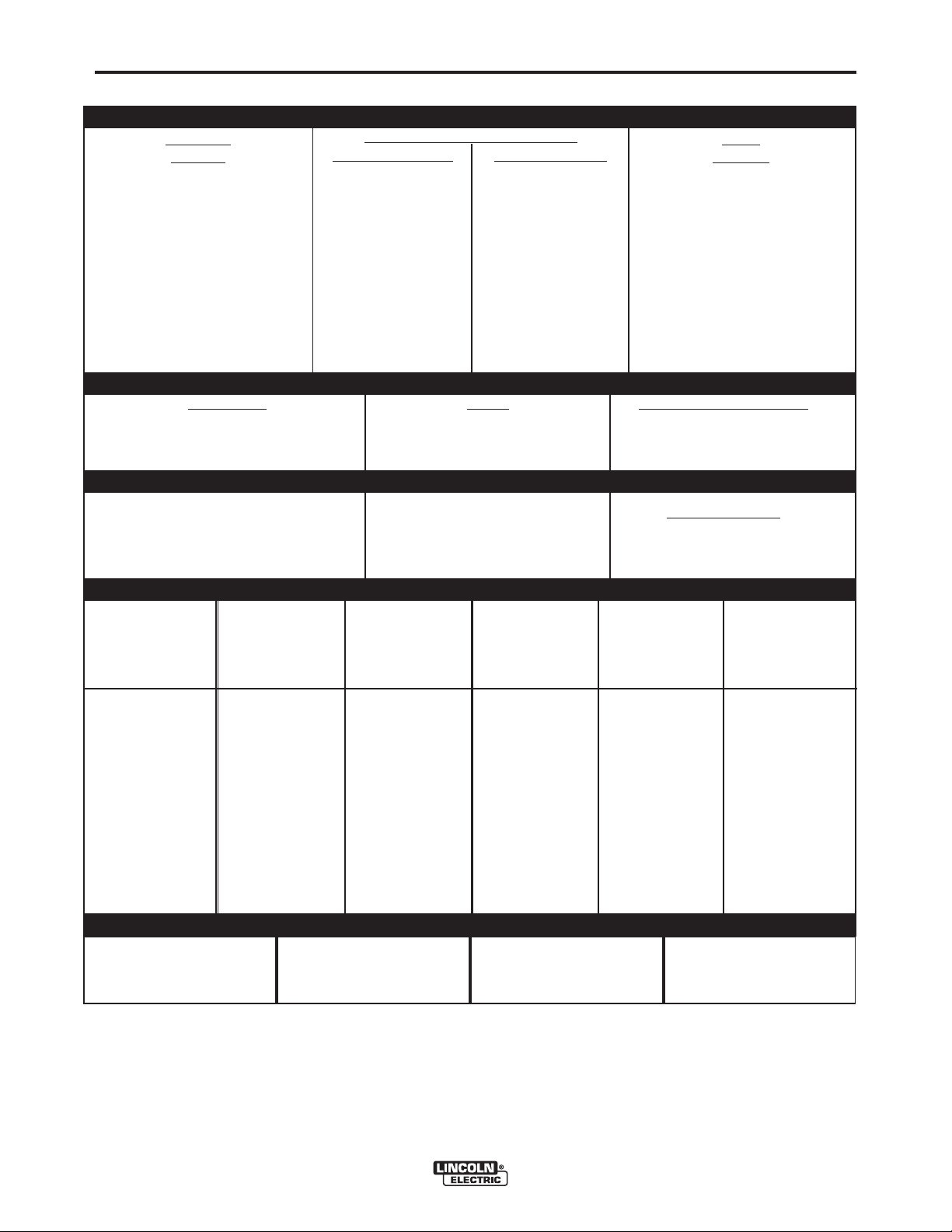
TECHNICAL SPECIFICATIONS – CV-655
INPUT - THREE PHASE ONLY
Standard
Voltage
Input Current at Rated Output
100% Duty Cycle
60% Duty Cycle
A-1
Code
Number
230/460/60
230/460/575/60
208/416/60
460/60
575/60
230/400/50/60*
380/500/50/60*
440/50/60
200/400/50/60
415/50/60
100% Duty Cycle
NEMA Class I (100)*
60% Duty Cycle
Current Range
INPUT
VOLTAGE /
208
230
416
460
575
200
230
380
400
415
440
500
Duty Cycle
70-815
FREQUENCY
94/47
94/47/38
104/52
47
38
94/54
56/43
49
107/54
52
116/58
116/58/47
128/64
58
47
116/67
69/53
60
132/67
64
RATED OUTPUT
Amps
650
815
Volts at Rated Amperes
OUTPUT
Maximum Open Circuit Voltage
See the OPERATION section
48
RECOMMENDED INPUT WIRE AND FUSE SIZES
HERTZ
60
60
60
60
60
50/60
50/60
50/60
50/60
50/60
50/60
50/60
INPUT AMPERE
RATING ON
NAMEPLATE
104
94
52
47
38
107
94
56
54
52
49
43
TYPE 75°C
COPPER WIRE
IN CONDUIT
AWG(IEC-MM2) SIZES
40°C (104°F) Ambient
1 (43)
2 (34)
6 (14)
6 (14)
8 (8.4)
1 (43)
2 (34)
6 (14)
6 (14)
6 (14)
6 (14)
8 (8.4)
TYPE 75°C
GROUND WIRE
IN CONDUIT
AWG(IEC-MM2) SIZES
6 (14)
6 (14)
8 (8.4)
8 (8.4)
8 (8.4)
6 (14)
6 (14)
8 (8.4)
8 (8.4)
8 (8.4)
8 (8.4)
8 (8.4)
10120
10121
10122
10123
10124
10125
10126
10127
10128
10129
44
44
Auxiliary
for Auxiliary Power
information by model
Power
TYPE 75°C
(SUPER LAG)
OR BREAKER
SIZE (AMPS)
200 Amp
175 Amp
90 Amp
90 Amp
70 Amp
200 Amp
175 Amp
100 Amp
100 Amp
90 Amp
90 Amp
80 Amp
1
PHYSICAL DIMENSIONS
HEIGHT
27.5 in
699 mm
* European models meet IEC974-1 standards.
1
Also called “inverse time” or “thermal/magnetic” circuit breakers; circuit breakers which have a delay in tripping action that decreases as the magnitude of the current increases.
WIDTH
22.2 in
564 mm
CV-655
DEPTH
38.0 in
965 mm
WEIGHT
652 lbs.
283 kg.
Page 11
A-2
INSTALLATION
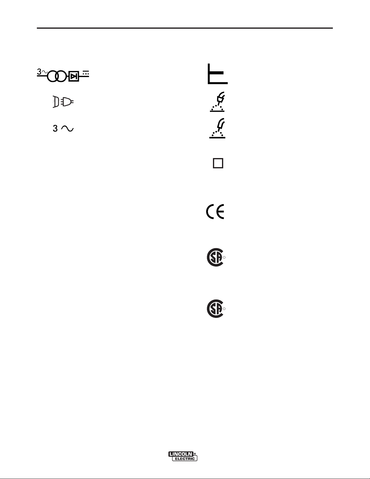
GRAPHIC SYMBOLS THAT APPEAR ON
RATING PLATE (LOCATED ON CASE BACK)
A-2
NEMA EW 1 (100%)
IEC 974-1
3 Phase transformer with
rectified DC output
INPUT POWER
THREE PHASE
Designates welder complies with
National Electrical Manufacturers
Association requirements EW 1
Class I with 100% duty cycle at
650Amps output. (Domestic,
Canadian, and Export models)
Designates welder complies with
International Electrotechnical
Commission requirements 974-1.
(European Models)
S
NRTL/C
Constant Voltage Output
Characteristics
GMAW
FCAW
Designates welder can be used
in environments with increased
hazard of electric shock.
(European models)
Designates welder complies with
low voltage directive and with
EMC directive. (European
models)
Designates welder complies with
R
both Underwriters Laboratories
(UL) standards and Canadian
Standards Association (CSA)
standards. (Canadian Model)
CV-655
NRTL
R
Designates welder complies with
Underwriters Laboratories (UL)
standards. (Domestic Models)
Page 12

A-3
INSTALLATION
A-3
Read entire installation section before starting
installation.
SAFETY PRECAUTIONS
WARNING
ELECTRIC SHOCK can kill.
• Only qualified personnel should
perform this installation.
• Turn the input power OFF at the disconnect switch or fuse box before working on
this equipment.
• Turn the Power switch on the CV-655
“OFF” before connecting or disconnecting output cables, wire feeder or remote
connections, or other equipment.
• Do not touch electrically hot parts.
• Always connect the Idealarc CV-655
grounding terminal (located on the welder
near the reconnect panel) to a good
electrical earth ground.
SELECT SUITABLE LOCATION
Place the welder where clean cooling air can freely
circulate in through the front louvers and out through
the rear louvers. Dirt, dust or any foreign material that
can be drawn into the welder should be kept at a
minimum. Failure to observe these precautions can
result in excessive operating temperatures and
nuisance shut-downs.
STACKING
The CV-655 may be stacked three-high provided the bottom
machine is on a stable, hard, level surface. Be sure that the
two pins in the roof fit into the slots in the base of the CV655 above it.
TILTING
INPUT
CONTACTOR (CR1)
INPUT POWER SUPPLY
CABLE WITH BUSHING
OR BOX CONNECTOR
FIGURE A.1 ELECTRICAL INPUT CONNECTIONS
RECONNECT
PANEL ASSEMBL Y
ELECTRICAL
INPUT CONNECTIONS
Before installing the machine check that the input supply
voltage, phase, and frequency are the same as the voltage, phase, and frequency as specified on the welder
nameplate.
Use input wire sizes that meet local electrical codes or
see the Technical Specifications page in this manual.
Input power supply entry is through the hole in the Case
Back Assembly. See Figure A.1 for the location of the
machine’s input cable entry opening, Input Contactor
(CR1), and reconnect panel.
FUSE AND WIRE SIZES
Protect the input circuit with the super lag fuses or delay
type circuit breakers listed on the Technical
Specifications page of this manual for the machine
being used. They are also called inverse time or thermal/magnetic circuit breakers.
Do not place the machine on a surface that is inclined
enough to create a risk of the machine falling over.
ELECTROMAGNETIC COMPATIBILITY (EMC)
The EMC classification of the CV-655 is Industrial, Scientific
and Medical (ISM) group 2, class A.
The CV-655 is for industrial use only. (See prints L10093-1,
-2 safety pages in the Front of Instruction Manual for further
details).
Locate the CV-655 away from radio controlled machinery.
The normal operation of the CV-655 may adversely affect
the operation of RF controlled equipment, which may result
in bodily injury or damage to the equipment
.
CV-655
DO NOT use fuses or circuit breakers with a lower amp
rating than recommended. This can result in “nuisance”
tripping caused by inrush current even when machine is
not being used for welding at high output currents.
GROUND CONNECTION
Ground the frame of the machine. A ground
terminal marked with the symbol ( ) is located inside
the case back of the machine near the input contactor.
Access to the input box assembly is at the upper rear of
the machine. See your local and national electrical
codes for proper grounding methods. Use grounding wire
sizes that meet local electrical codes or see the
Technical Specifications page in this manual.
Page 13
A-4
INSTALLATION
A-4
INPUT POWER SUPPLY CONNECTIONS
A qualified electrician should connect the input power
supply leads.
1. Follow all national and local electrical codes.
2. Use a three-phase line.
3. Remove the input access door at upper rear of the
machine.
4. Follow input supply connection diagram located
on the inside the door.
5. Connect the three-phase AC power supply leads
L1, L2, and L3 to the input contactor
terminals in the input box assembly. See Figure
A.1.
RECONNECT PROCEDURE
WARNING
Electric Shock Can Kill
• Disconnect input power before performing this procedure.
------------------------------------------------------------------------
Multiple voltage machines are shipped connected to
the highest input voltage listed on the machine’s rating
plate. Before installing the machine, check that the
reconnect panel in the input box assembly is connected for the proper voltage.
CAUTION
Failure to follow these instructions can cause immediate failure of components within the machine.
------------------------------------------------------------------------
When powering welder from generator be sure to turn
off welder first, before generator is shut down, in order
to prevent damage to welder!
To reconnect a multiple voltage machine to a different
voltage, remove input power and follow the input connection diagram located on the inside of case back
input access door.
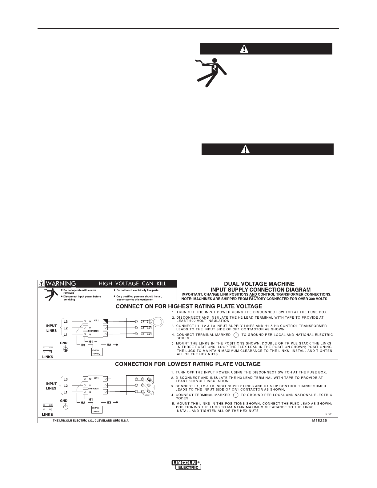
1. For dual voltage sample machine reconnect
instructions, see Figure A.2.
FIGURE A.2 Dual Voltage Machine Reconnection Procedure
CV-655
Page 14
A-5
INSTALLATION
A-5
OUTPUT CONNECTIONS
ELECTRODE AND WORK CABLES
Use the shortest possible cable lengths. See Table
A.1 for recommended cable sizes based on length.
TABLE A.1
Cable Sizes for Combined Lengths of Copper
Electrode and Work Cable
Cable Length
ft. (m)
0 (0) to 100 (30.4)
100 (30.4) to 200 (60.8)
200 (60.8) to 250 (76.2)
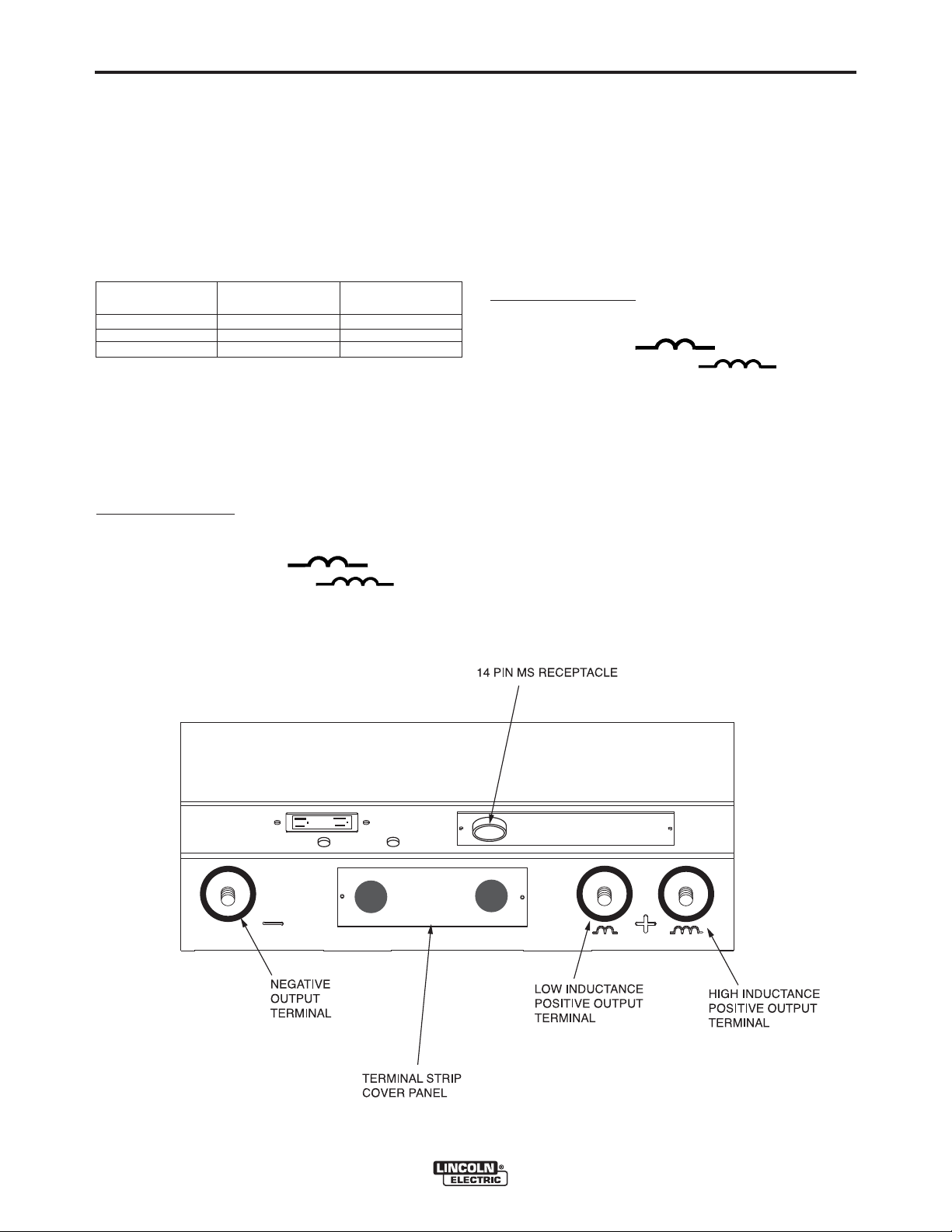
The output terminals are located at the lower front of
the welder behind a hinged door Refer to figure A.3.
Route the welding cables through the slotted strain
reliefs of the base to the welding terminals.
For Positive Polarity:
1. Connect the electrode cable to either the low inductance terminal (marked " ") or the high
inductance terminal (marked " "). See
OPERATION section “Positive Output Terminals”
for an explanation of the use of high or low inductance terminals.
Parallel Cables Cable Size
2
2
2
2/0 ( 70mm2)
3/0 ( 95mm2)
4/0 (120mm2)
2. Connect the work cable to the negative terminal
marked “-”.
3. Remove the terminal strip access cover panel on
the lower case front. Refer to figure A.3 for the
location.
4. Work Sense lead #21 from the 14 Pin MS-receptacle must be connected to “-21”on the terminal strip.
Note: This is how the CV-655 is shipped from
the factory.
5. Replace the terminal strip access cover panel.
For Negative Polarity:
1. Connect the work cable to either the low inductance
terminal (marked " ") or the high inductance terminal (marked " "). See
OPERATION section “Positive Output Terminals”
for an explanation of the use of high or low inductance terminals.
2. Connect the electrode cable to the negative terminal marked “-”.
3. Remove the terminal strip access cover panel on
the lower case front. Refer to figure A.3 for the
location.
4. Work Sense lead #21 from the 14 Pin MS-receptacle must be connected to “+21”on the terminal strip.
5. Replace the terminal strip access cover panel.
FIGURE A.3 Output Connections
CV-655
Page 15
A-6
INSTALLATION
A-6
AUXILIARY POWER AND
CONTROL CONNECTIONS
Located at the lower front of the welder behind a
hinged door is a 115VAC duplex receptacle for auxiliary power (Domestic and Canadian Models only) and
a 14 Pin MS type receptacle for connection of auxiliary equipment such as wire feeders. Also, terminal
strips with 115VAC and connections for auxiliary
equipment are located behind the access panel on the
lower case of the welder. A 220VAC receptacle for a
water cooler (European and Export Models only) is
located on the case back.
AUXILIARY POWER TABLE
Voltage and Circuit Breaker Ratings at Auxiliary Power
Auxiliary Domestic Canadian European Export
Power Models Model Models Models
Connections (60Hz)
At Duplex 115V 20A 115V 15A No Duplex No Duplex
Receptacle
Terminal strip 115V 20A 115V 15A 115V 15A 115V 15A
terminals 31 & 32
MS-Receptacle 115V 20A 115V 15A
pins A & J
MS-Receptacle 42V 10A 42V 10A 42V 10A 42V 10A
pins I & K
At 220V
Receptacle
Connections for Various Models
(230/460/575V/60 Hz)
No Receptacle No Receptacle 220V 2A 220V 2A
(50/60 Hz) (50/60 Hz)
Open Circuit
115V 15A
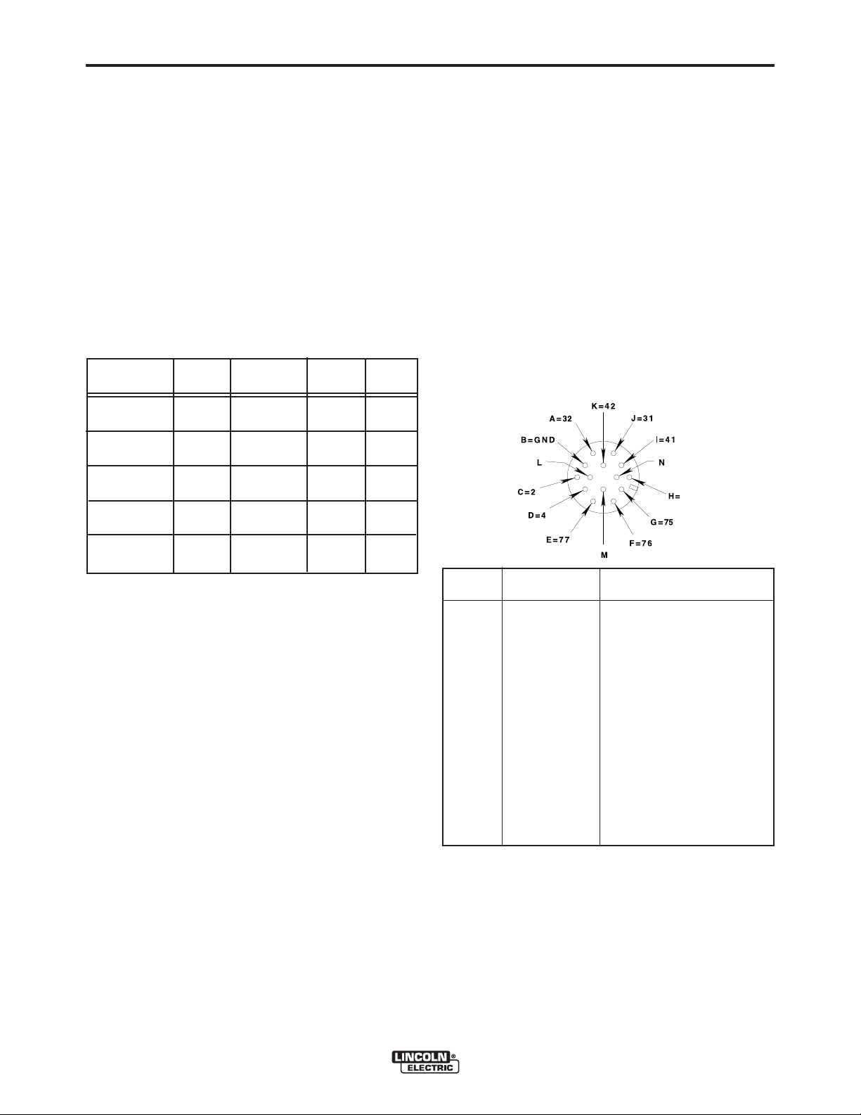
14 PIN MS TYPE RECEPTACLE
(For MS3106A-20-27PX Plug. L.E.C. Part #S12020-32)
Refer to the figure A.4 for the available circuits in the
14 pin receptacle.
42 VAC is available at receptacle pins I and K.
A 10 amp circuit breaker protects this circuit.
115 VAC is available at receptacle pins A and J
(Domestic, Canadian and Export Models). This circuit
is protected by a circuit breaker (see Auxiliary Power
Table). Note that the 42 VAC and 115 VAC circuits
are electrically isolated from each other. However, on
the European model one line of the 115VAC is connected to chassis ground.
FIGURE A.4 FRONT VIEW OF 14-PIN CONNECTOR
RECEPTACLE
115VAC DUPLEX RECEPTACLE (DOMESTIC AND
CANADIAN MODELS ONLY)
The 115VAC duplex receptacle is protected by a circuit breaker located below the receptacle (see
Auxiliary Power Table). Receptacle is a NEMA 5-20R
(protected by a 20 amp breaker) on Domestic Models
and a NEMA 5-15R (protected by a 15 amp breaker)
on Canadian Models.
230VAC RECEPTACLE (EUROPEAN AND EXPORT
MODELS ONLY)
A Continental European receptacle is located on the
rear panel for supplying 220VAC to a water cooler.
The receptacle has a protective cover to prevent incidently contact and is a Schuko type. The circuit is protected by a 2 amp circuit breaker also located on the
rear panel. This circuit is electrically isolated from all
other circuits, but on the European Models one line is
connected to chassis ground.
PIN LEAD NO. FUNCTION
A 32 115 VAC
B GND Chassis Connection
C 2 Trigger Circuit
D 4 Trigger Circuit
E 77 Output Control
F 76 Output Control
G 75 Output Control
H 21 Work Sense Connection
I 41 42 VAC
J 31 115 VAC
1.
K 42 42 VAC
L --- --M --- --N --- ---
1.
115VAC circuit is not present on IEC 974-1 models.
2.
As shipped from the factory Lead #21 from the 14 Pin connector is
connected to “-21” on the terminal strip. This is the configuration
for positive welding. If welding negative polarity, connect lead #21
to the “+21” connection point on the terminal strip.
2
CV-655
Page 16

A-7
INSTALLATION
TERMINAL STRIPS
Terminal strips are available behind the cover panel
on the lower case front to connect wire feeder control
cables that do not have a 14 Pin MS-type connector.
Refer to figure A.3 for the location of this cover panel.
These terminals supply the connections as shown in
the following Terminal Strip charts. See Auxiliary
Power Table for rating of circuit breaker in 115VAC
circuit. Remove a plug button from the terminal strip
cover and install an appropriate strain relief clamp for
the cable being used. NOTE: There are two work
sense lead connection points on the terminal strip.
Connect both the work sense lead #21 from the 14 pin
connector and #21 lead of the control cable to “-21”
when welding positive polarity or to “+21” when welding negative polarity.
TERMINAL STRIP 1 (T.S.1)
Lead No. Function
75 Output Control
76 Output Control
77 Output Control
A-7
TERMINAL STRIP 2 (T.S.2)
Lead No. Function
+21 Work Connection
-21 Work Connection
41 42 VAC
4 Trigger Circuit
2 Trigger Circuit
31 115 VAC
32 115 VAC
1.
115VAC circuit is not present on IEC 974-1 models.
2.
As shipped from the factory Lead #21 from the 14 Pin connector is
connected to “-21” on the terminal strip. This is the configuration
for positive welding. If welding negative polarity, connect lead #21
to the “+21” connection point on the terminal strip.
2
1
1
CV-655
Page 17

B-1
OPERATION
B-1
SAFETY PRECAUTIONS
Read and understand this entire section before operating the machine.
GENERAL WARNINGS
WARNING
ELECTRIC SHOCK
can kill.
• Do not touch electrically live parts
or electrode with skin or wet
clothing.
• Insulate yourself from work and
ground.
• Always wear dry insulating
gloves.
FUMES AND GASES
can be dangerous.
• Keep your head out of fumes.
GENERAL DESCRIPTION
The CV-655 is an energy efficient constant voltage DC power
source that produces outstanding arc characteristics.
Four models are available:
Domestic - all 60 Hertz models except 230/460/575v.
NEMA Class 1 rated
Canadian - 230/460/575v 60 Hertz
NEMA Class 1 rated
European - 50/60 Hertz models rated for IEC 974-1
Export - 50/60 Hertz models NEMA Class 1 rated
RECOMMENDED PROCESSES AND
EQUIPMENT
The CV-655 is designed for GMAW (MIG), FCAW,
(except NR-203 family electrodes) and CV semi-automatic submerged arc welding processes (SAW), plus
the capability of air carbon arc gouging (AAC) up to
3/8” (10mm) diameter carbons. Limited CV automatic
submerged arc welding with 5/64” and smaller wires.
The CV-655 is recommended for use with Lincoln’s
DH-10 or LN-10 as well as the LN-7*, LN-7 GMA*, LN742, LN-8*, LN-9*, LN-9 GMA*, LN-23P and LN-25
semiautomatic wire feeders. It is also recommended
for use with the NA-3, NA-5 and NA-5R automatic
feeders, but “cold starting” for sub-arc cannot be used
(it must be jumpered out).
• Use ventilation or exhaust to
remove fumes from breathing
zone.
WELDING SPARKS
can cause fire or
explosion
• Keep flammable material away.
• Do not weld on containers that
have held combustibles.
ARC RAYS
can burn.
• Wear eye, ear and body
protection.
Observe additional Safety Guidelines detailed
throughout this manual.
* The 14-pin MS receptacle on the European models
does not provide 115 VAC for these feeders; 115 VAC
must be obtained from terminal strip.
There are no provisions on the CV-655 for paralleling.
DESIGN FEATURES AND ADVANTAGES
• Two inductance positions: operator can choose the optimum arc characteristics.
• Power on/off switch with pilot light and thermostat tripped
indicator light.
• Full range output voltage control for easy operation.
• Panel switches for remote or local output control, and output on or remote selection.
• Hinged cover to protect output terminals and auxiliary connections.
• 42 VAC, 10 amp auxiliary power available for the wire
feeder; circuit breaker protected.
CV-655
Page 18

B-2
OPERATION
DESIGN FEATURES AND ADVANTAGES
(CONT’D)
• 115 VAC, auxiliary power available for the wire
feeder; circuit breaker protected. 20 amp breaker on
Domestic model and 15 amp breaker on Canadian,
European, and Export Models.
• 115VAC duplex plug receptacle available on
Domestic and Canadian Models. 20 amp breaker on
Domestic Models and 15 amp breaker on Canadian
Model.
• Single MS-type (14-pin) connection for wire feeder.
• Thermal Fan Control with electronic and thermostatic
protection for current overload and excessive temperatures.
• Optional Field Installed Digital or Analog
Voltmeter/Ammeter kits are available.
• 220 VAC receptacle on European and Export models for connecting to a water cooler. Protected by 2
amp breaker.
B-2
WELDING CAPABILITY
The CV-655 has the following Output and Duty Cycle
based on operation for a 10 minute period:
650 Amps, 44 Volts at 100%
815 Amps, 44 Volts at 60%
CV-655
Page 19

B-3
OPERATION
B-3
CONTROLS AND SETTINGS
All operator controls and adjustments are located on the case front of the CV-655. Refer to Figures B.1, and B.2
and corresponding explanations.
7
3
CV-655
FIGURE B.1 CONTROL PANEL CONTROLS
1. INPUT POWER ON/OFF SWITCH - This tog-
gle switch turns the machine on or off. Putting the
switch in the ON position energizes the
machine’s input contactor applying input power to
the machine. Switching the switch to the
OFF position de-energizes the input contactor.
2. PILOT LIGHT - When the power switch is in the
ON position the machine’s white pilot light will illuminate. If the input contactor de-energizes the
machine in an overload situation the pilot will still
illuminate. In this situation it will be necessary to
reset the machine by switching the power switch to
the OFF then ON position. (See Overload
Protection Section)
3. OUTPUT VOLTAGE CONTROL - This control
provides continuous control of the machine’s output
voltage from minimum to maximum (typical full pot
range between 15 to 44 volts) as it is rotated clockwise.
4. OUTPUT TERMINALS ON/REMOTE - When this
switch is in the REMOTE position, the CV-655’s
output terminals will be electrically “cold” until a
remote device such as a wire feeder closes the #2
and #4 circuit in the MS-receptacle or terminal strip.
When this switch is in the ON position the
2
6
1
4
machine’s output terminals will be electrically energized all the time.
5. LOCAL/REMOTE CONTROL SWITCH - When this
switch is set to the LOCAL position, control of
the output voltage is via the output voltage control
on the CV-655’s control panel. When this switch is
set to the REMOTE position, control is through
a remote source such as a wire feeder via the #75,
#76, and #77 leads in the MS-receptacle or terminal
strip.
6. THERMAL PROTECTION LIGHT - If the
machine overheats due to lack of proper air flow
through the machine or due to exceeding the
machine’s duty cycle, thermostats will disable the
welding output and this light will illuminate. Input
power is still applied to the machine and the cooling
fan will continue to run. When the machine cools
the welding output will resume.
7. OPTIONAL VOLTMETER & AMMETER - Digital
or analog meter kits are available as field installed
options. Refer to the Accessories Section of this
manual.
5
CV-655
Page 20

B-4
OPERATION
B-4
1 2
6
FIGURE B.2 LOWER CASE FRONT CONTROLS & CONNECTIONS
1. 115VAC DUPLEX RECEPTACLE (Domestic and
Canadian Models) This receptacle provides up to
20 amps of 115 VAC auxiliary power on the
Domestic Models and up to 15 amps on the
Canandian Model.
2. 115VAC CIRCUIT BREAKER - This breaker
protects the 115 VAC auxiliary circuits located in
the duplex receptacle, terminal strip and MS- receptacle. Breaker is rated 20 amps on Domestic
Models and 15 amps on all other models.
3. 42VAC 10 AMP CIRCUIT BREAKER - This
breaker protects the 42VAC auxiliary circuits located in the terminal strip and MS-receptacle.
4. 14 PIN MS-RECEPTACLE - This connector pro-
vides easy connection for a wire feeder control
cable. It provides connections for auxiliary power,
output switching, remote output control, wire feeder
voltmeter sense lead and ground. Refer to 14 Pin
MS Type Receptacle in the Installation Section of
this manual for information about the circuits made
available at this receptacle.
3
welding polarity and for proper welding cable size
refer to Electrode and Work Cables in the
Installation Section of this manual.
7. POSITIVE OUTPUT TERMINALS - These output
terminals are for connecting a welding cable to
either the High Inductance
or Low Inductance
Terminal for desired arc characteristics. High
Inductance is recommended for Stainless Steel
welding. Low Inductance is recommended for Short
Arc GMAW. For Spray Arc and other processes
either may be used to provide the preferred starting
and welding arc characteristics: High Inductance
will provide a “softer” arc, but will not provide as
“crisp” of an arc start as the Low Inductance. To
change welding polarity and for proper welding
cable size refer to Electrode and Work Cables in
the Installation Section of this manual.
4
5
7
5. TERMINAL STRIP COVER PANEL - Remove this
panel to gain access to the circuits made available
at the terminal strip. This terminal strip contains the
same circuits as the 14 pin MS-receptacle. The
cover also provides for installation of cable strain
relief clamps.
6. NEGATIVE OUTPUT TERMINAL - This output ter-
minal is for connecting a welding cable. To change
CV-655
Page 21

B-5
OPERATION
B-5
CASE BACK CONNECTIONS
220VAC AUXILIARY RECEPTACLE
(European and Export Models)
This receptacle provides up to 2 amps of 220VAC
auxiliary power for a water cooler.
220VAC 2 AMP CIRCUIT BREAKER
(European and Export Models)
This breaker protects the 220VAC auxiliary circuit
located in the 220VAC receptacle.
CAUTION
When using a CV-655 with wire feeders, there will be
a small spark if the electrode contacts the work or
ground with several seconds after releasing the trigger.
When used with some wire feeders with the electrical
trigger interlock in the ON position, the arc might
restart if the electrode touches the work or ground
during these several seconds.
------------------------------------------------------------------------
AUXILIARY POWER
42 volt AC auxiliary power, as required for some wire
feeders, is available through the wire feeder receptacle. A 10 amp circuit breaker protects the 42 volt circuit from overloads.
CV-655 machines can also supply 115 volt AC auxiliary power through the wire feeder receptacle. A 20
amp circuit breaker on the Domestic model, and a 15
amp on the Canadian and Export models protects the
115 volt circuit from overloads. 115VAC is not available in the MS-receptacle on the European models.
THERMAL FAN CONTROL
The machine’s cooling fan remains off when the temperature of the rectifiers and windings inside the
machine are below that requiring air flow cooling, as
determined by electronic monitoring of several thermal
sensors and the welding current of the machine. The
fan may remain off until welding begins, but once the
fan is activated, it will remain on for at least 5 minutes
to assure proper cooling. This feature saves energy
and also minimizes the amount of dirt and other air
borne particles being drawn into the machine.
OVERLOAD PROTECTION
This welder has thermostatic protection from excessive duty cycles, overloads, loss of cooling, and high
ambient temperatures. When the welder is subjected
to an overload or loss of cooling, a thermostat will
open. This condition will be indicated by the illumination of the yellow Thermostatic Protection Light on the
case front (see Figure B.1).The fan will continue to run
to cool the power source. No welding is possible until
the machine is allowed to cool and the Thermostatic
Protection Light goes out.
The CV-655 also has over-current protection. When
the load exceeds a threshold current (about 900
amps), overcurrent shut down will occur after a period
of time that shortens as the current increases beyond
this threshold. If the current reaches about 1000
amps the output will be “clamped” at about 1000 amps
and shut down will occur in about 5 seconds. When
this overload shut down occurs the short circuit output
of the machine drops to only about 20 amps on 60Hz,
40 amps on 50Hz, but the input contactor and input
pilot light will remain on until reset by turning the
power switch off, then back on with overload removed.
CAUTION
Note that some types of equipment, especially pumps
and large motors, have starting currents which are
significantly higher than their running current. These
higher starting currents may cause the circuit breaker
to open. If this situation occurs, the user should refrain
from using the CV-655 auxiliary power for that equipment.
___________________________________________
FAN MOTOR FUSE (EUROPEAN MODEL)
A 10 amp slow blow fuse protects the fan motor circuit. This fuse is located inside the CV-655 mounted
on the fan motor bracket.
CV-655
Page 22

C-1
T
ACCESSORIES
C-1
The CV-655 can be used to power any of
the following Lincoln Wire feeders:
SEMI-AUTOMATIC WIRE FEEDERS
• DH-10 • LN-9*
• LN-10 • LN-9 GMA*
• LN-7 GMA* • LN-23P
• LN-742 • LN-25
• LN-7 • LN-8*
AUTOMATIC WIRE FEEDERS*
#
• NA-3 • NA-5R
• NA-5
* European CV-655 models only provide 115VAC for these feeders at the
terminal strip (TS2)
#
“Cold starting for sub-arc cannot be used. (It must be jumpered out. See
Auto Feeder manual)
FIELD INSTALLED OPTIONS
K1482-1 Digital Ammeter/Voltmeter Kit - Installs
easily to the front control panel and provides digital
display of actual welding voltage and amperage while
welding. (Installation instructions are included with the
kit).
K1483-1 Analog Ammeter/Voltmeter Kit - Installs
easily to the front control panel and provides analog
display of actual welding voltage and amperage while
welding. (Installation instructions are included with the
kit).
NOTE: A dirty air filter may cause the thermal protection of the CV-655 to prematurely activate. Remove
and blow out, or wash and dry, the filter every two
months, or less if in extremely dirty conditions.
Replace if necessary.
Undercarriage (K817P, K842) - The CV-655 is
designed for use with the Lincoln K817P or K842
Undercarriage. Complete installation instructions are
included with each undercarriage. When any of the
undercarriages are installed, the CV-655 lift bail is no
longer functional. Do not attempt to lift the machine
with the undercarriage attached. The undercarriage is
designed for moving the machine by hand only.
Mechanized towing can lead to injury and /or damage
to the CV-655.
REMOTE OUTPUT CONTROL
(K775 or K857 WITH K864 ADAPTER)
An optional “remote output control” is available. This is
the same remote control that is used on other Lincoln
power sources (K775). The K775 consists of a control
box with 28 ft (8.5m) of four conductor cable. This connects to terminals 75, 76, and 77 on the terminal strip
and the case grounding screw so marked with the symbol on the machine. These terminals are located
behind the cover panel on the lower connection panel of
the CV-655. This control will give the same control as
the output control on the
machine.
The K857 has a 6-pin MS-style connector. The K857
requires a K864 adapter cable which connects to the
14-pin connector on the CV-655.
K1484-1 Dual Feeder Kit - This kit replaces the 14
Pin MS-receptacle panel on the lower case front of the
REMOTE CONTROL ADAPTER CABLE (K864)
CV-655. It provides two 14 Pin MS-receptacles and a
built in transfer circuit for connecting and operating
two like-polarity wire feeders. European CV-655 mod-
STRAIGHT PLUG (14 PIN)
O POWER SOURCE
CABLE RECEPTACLE (6 SOCKET)
TO: K857 REMOTE CONTROL
els can only use 42V feeders with this kit. (Installation
instructions are included with the kit).
CABLE RECEPTACLE (14 SOCKET)
K1485-1 Cable Hanger Bracket - Mounts over stan-
TO: LN-7 WIRE FEEDERS
dard lift bale of the CV-655 and provides a cable
hanger on both sides of the power source, each side
capable of holding up to 100 ft. of weld cable.
(Installation instructions are included with the kit).
K1486-1 Air Filter Kit - Removable metal filter easily
slides in and out of a bracket which mounts to the
A “V” cable 12” (.30m) long to connect a K857
Remote Control (6 pin connector) with a wire-feeder
(14-pin connector) and the machine (14-pin connector). If a remote control is used alone the wire-feeder
connection is then not used.
front of the CV-655. Filter is designed to trap 80% of
entering particles which are 5 microns, or larger, in
size. (Installation instructions are included with the
kit).
CV-655
Page 23

D-1
MAINTENANCE
SAFETY PRECAUTIONS
WARNING
ELECTRIC SHOCK can kill.
• Only qualified personnel should
perform this maintenance.
• Turn the input power OFF at the
disconnect switch or fuse box
before working on this
equipment.
• Do not touch electrically hot
parts.
GENERAL MAINTENANCE
1. The fan motor has sealed bearings which require
no service.
D-1
2. In extremely dusty locations, dirt may restrict the
cooling air causing the welder to run hot with premature tripping of thermal protection. Blow out the
welder with low pressure air at regular intervals to
eliminate excessive dirt and dust build-up on internal parts.
3. Periodically check the welding cables. Inspect for
any slits or punctures. Also make sure that all connections are tight.
CV-655
Page 24

E-1
TROUBLESHOOTING
HOW TO USE TROUBLESHOOTING GUIDE
WARNING
Service and Repair should only be performed by Lincoln Electric Factory Trained Personnel.
Unauthorized repairs performed on this equipment may result in danger to the technician and
machine operator and will invalidate your factory warranty. For your safety and to avoid
Electrical Shock, please observe all safety notes and precautions detailed throughout this
manual.
__________________________________________________________________________
This Troubleshooting Guide is provided to
help you locate and remedy possible problems with machine setup or operation.
Simply follow the three-step procedure
listed below.
Step 1. LOCATE PROBLEM (SYMPTOM).
Look under the column labeled “PROBLEM
(SYMPTOMS)”. This column describes possible symptoms that the machine may
exhibit. Find the listing that best describes
the symptom that the machine is exhibiting.
Step 2. PERFORM EXTERNAL TESTS.
The second column labeled “POSSIBLE
AREAS OF MISADJUSTMENT(S)” lists the
obvious external possibilities that may contribute to the machine symptom. Perform
these tests/checks in the order listed. In
general, these tests can be conducted without removing the case wrap-around cover.
Step 3. PERFORM COMPONENT TESTS.
If you have exhausted all of the recommended tests in Step 2, Consult your Local
Authorized Field Service Facility.
E-1
CAUTION
If for any reason you do not understand the test procedures or are unable to perform
the tests/repairs safely, contact your LOCAL AUTHORIZED LINCOLN ELECTRIC
FIELD SERVICE FACILITY for assistance before you proceed.
_____________________________________________________________________
CV-655
Page 25

E-2
TROUBLESHOOTING
Observe all Safety Guidelines detailed througout this manual
E-2
PROBLEMS
(SYMPTOMS)
Input contactor (CR1) chatters.
Machine input contactor does not
operate.
POSSIBLE
CAUSE
PROBLEMS
1. Faulty input contactor (CR1).
2. Low line voltage.
1. Make sure the proper threephase input power is applied to
the CV655 machine.
2. The input contactor may be
faulty.
3. The power switch (SW1) may be
faulty.
4. The pilot transformer may be
faulty.
RECOMMENDED
COURSE OF ACTION
Machine input contactor operates,
but no output when trying to weld.
1. Electrode or work cables may be
loose or broken.
2. Firing P.C. board is not connected
or is faulty. See PC board LED
information.
4. Trigger circuit may not be working.
Place Output Terminals Switch to
the ON position, or place a jumper
wire across #2 and #4 on the terminal strip. LED 6 on the control
PC board should go ON. If it does
not light check for opens in the #2
and #4 circuit. See wiring diagram. If LED 6 does light the control board may be faulty.
5. If the thermal protection light is
ON the machine is overheated.
The choke or secondary thermostats may be open. Make
sure the fan is operating and
remove the cause of the overheating problem. See PC board
LED information.
If all recommended possible areas
of misadjustments have been
checked and the problem persists,
contact your local Lincoln
Authorized Field Service Facility.
CAUTION
If for any reason you do not understand the test procedures or are unable to perform the tests/repairs safely, contact your
Local Lincoln Authorized Field Service Facility for technical troubleshooting assistance before you proceed.
CV-655
Page 26

E-3
TROUBLESHOOTING
Observe all Safety Guidelines detailed througout this manual
E-3
PROBLEMS
(SYMPTOMS)
Machine has maximum output, but
no control.
PPOSSIBLE
CAUSE
PROBLEMS
1. Check the Local/Remote output
switch (SW3) and associated
leads. See wiring diagram.
2. Make sure the remote control
leads #75, #76 and /or #77 are
NOT grounded to the negative
welding output.
3. The output control potentiometer
may be faulty.
4. The control board or control
board transformer (T3) may be
faulty.
RECOMMENDED
COURSE OF ACTION
Machine has minimum output and no
control.
Machine does not have maximum
output.
Poor arc striking with semiautomatic
or automatic wire feeders.
1. The remote control leads #75,
#76 and/or #77 may be grounded
to the positive welding output.
1. Make sure the correct threephase input is applied to the
CV655 machine.
2. The output control potentiometer
may be faulty.
3. The Local/Remote switch (SW3)
may be faulty.
4. The control or firing boards may
be faulty. See PC board LED
information.
1. Make sure the welding cables
and connections are secure.
2. Check for correct welding porcedures.
If all recommended possible areas
of misadjustments have been
checked and the problem persists,
contact your local Lincoln
Authorized Field Service Facility.
CAUTION
If for any reason you do not understand the test procedures or are unable to perform the tests/repairs safely, contact your
Local Lincoln Authorized Field Service Facility for technical troubleshooting assistance before you proceed.
CV-655
Page 27

E-4
TROUBLESHOOTING
Observe all Safety Guidelines detailed througout this manual
E-4
PROBLEMS
(SYMPTOMS)
Variable or sluggish welding arc.
Machine will not shut off.
Output Control Pot not functioning in
“Local” control.
PPOSSIBLE
CAUSE
PROBLEMS
1. Make sure the welding cables are
sized correctly and the connections are tight.
2. Make sure the welding proce-
dures are correct.
1. The input power switch (SW1)
may be faulty.
2. The input contactor (CR1) may
be faulty.
1. Check the Local/Remote control
switch and associated leads.
See wiring diagram.
2. The machine output control
potentiometer may be faulty.
Also check associated leads.
See wiring diagram.
RECOMMENDED
COURSE OF ACTION
If all recommended possible areas
of misadjustments have been
checked and the problem persists,
contact your local Lincoln
Authorized Field Service Facility.
No output control in “Remote” control.
1. Output Control Switch in wrong
position.
2. Faulty Output Control Switch.
3. Faulty Remote Control Pot.
4. Leads or connections open in con-
trol circuit. (#75, #76, #77)
CAUTION
If for any reason you do not understand the test procedures or are unable to perform the tests/repairs safely, contact your
Local Lincoln Authorized Field Service Facility for technical troubleshooting assistance before you proceed.
CV-655
Page 28

E-5
TROUBLESHOOTING
Observe all Safety Guidelines detailed througout this manual
E-5
PROBLEMS
(SYMPTOMS)
Machine will not weld. OCV is less
than 1 volt.
The wire feeder will not come on.
Poor starting.
POSSIBLE
CAUSE
PROBLEMS
1. The machine may be in a overload condition. Remove the short
circuit or excessive load on the
output terminals.
2. See the PC board LED information.
1. Either the 42VAC or the 115VAC
circuit breakers may be tripped.
Reset if necessary.
2. Check for the presence of the
required voltage to operate the
wire feeder.
3. The control cable or wire feeder
may be faulty.
1. The capacitor discharge resistor
(R2) may be faulty. See wiring
diagram.
2. The control board may be faulty.
See PC board LED information.
RECOMMENDED
COURSE OF ACTION
If all recommended possible areas
of misadjustments have been
checked and the problem persists,
contact your local Lincoln
Authorized Field Service Facility.
CAUTION
If for any reason you do not understand the test procedures or are unable to perform the tests/repairs safely, contact your
Local Lincoln Authorized Field Service Facility for technical troubleshooting assistance before you proceed.
CV-655
Page 29

E-6
TROUBLESHOOTING
Observe all Safety Guidelines detailed througout this manual
E-6
PROBLEMS
(SYMPTOMS)
Poor arc characteristics.
POSSIBLE
CAUSE
PROBLEMS
1. The positive welding cable may be
connected to the wrong inductance tap.
2. The output capacitors may be
faulty. Warning:The liquid electrolyte in the these capacitors is
toxic. Avoid contact with any portion of your body. Clean up vented electrolyte using rubber gloves
and a water dampaned cloth.
Any electrolyte which gets on the
skin, clean with soap and water.
3. The control board may be faulty.
See PC board LED information.
RECOMMENDED
COURSE OF ACTION
115VAC receptacle not working.
(60HZ machines only)
1. Check the 115VAC circuit break-
er. Reset if necessary. Make
sure the load on the receptacle
does not exceed the rating of the
115VAC breaker (either 15A or
20A). See wiring diagram.
If all recommended possible areas
of misadjustments have been
checked and the problem persists,
contact your local Lincoln
Authorized Field Service Facility.
CAUTION
If for any reason you do not understand the test procedures or are unable to perform the tests/repairs safely, contact your
Local Lincoln Authorized Field Service Facility for technical troubleshooting assistance before you proceed.
CV-655
Page 30

E-7
TROUBLESHOOTING
Observe all Safety Guidelines detailed througout this manual
E-7
PROBLEMS
(SYMPTOMS)
Thermal Protection Light comes ON
and fan does not run.
NOTE: Fan is thermal controlled and
does not continuously run when
machine is powered up.
Fan runs continuously.
POSSIBLE
CAUSE
PROBLEMS
1. Check for obstructions that could
prevent the fan from turning.
2. Check the fan control ciruit. See
wiring diagram.
3. The fan motor may be faulty.
4. The Thermal Fan/Snubber PC
board may be faulty. See PC
board LED information.
1. The Thermal Fan Thermistor may
be faulty. See wiring diagram.
2. The Thermal Fan/Snubber PC
board may be faulty. See PC
board LED information.
RECOMMENDED
COURSE OF ACTION
One or both Digital Meters not lighting.
Digital Voltmeter not working properly or erratic display.
1. The meters may not be receiving
the voltages from the auxiliary
transformer. Check plug P13.
See wiring diagram.
2. The Digital meter PC board may
be faulty.
1. Meter may not be receiving auxil-
iary or sensing voltages. Make
sure plug P12 & P13 are securely
plugged into the Digital meter PC
board and also plug P3 is securely
plugged into the control board.
2. The may be an open in the volt-
age feedback circuit. See wiring
diagram.
3. The Digital meter PC board may
be faulty.
If all recommended possible areas
of misadjustments have been
checked and the problem persists,
contact your local Lincoln
Authorized Field Service Facility.
CAUTION
If for any reason you do not understand the test procedures or are unable to perform the tests/repairs safely, contact your
Local Lincoln Authorized Field Service Facility for technical troubleshooting assistance before you proceed.
CV-655
Page 31

E-8
TROUBLESHOOTING
Observe all Safety Guidelines detailed througout this manual
E-8
PROBLEMS
(SYMPTOMS)
Digital Ammeter not working properly
or erratic display.
Analog Meters not reading, or not
reading correctly.
POSSIBLE
CAUSE
PROBLEMS
1. The meter PC board may not be
receiving the auxiliary or sensing
voltages. Check plug P3 and
plugs P12 & P13. See wiring
diagram.
2. The current feedback circuit may
be faulty. From the shunt to the
control board. See wiring diagram.
3. The Digital meter PC board may
be faulty.
1. The meters may not be receiving
voltage or current feedback signals. Make sure plug P3 is
securely plugged in the control
board and plug J14 (in-line connector) is securely seated in the
plug assembly from the control
board.
2. Check the current feedback and
voltage feedback circuits. See
wiring diagram.
RECOMMENDED
COURSE OF ACTION
If all recommended possible areas
of misadjustments have been
checked and the problem persists,
contact your local Lincoln
Authorized Field Service Facility.
3. The meter(s) may be defective.
220VAC receptacle not working.
(50/60 HZ machines only)
1. Check the circuit breaker. Reset
if necessary.
2. Check for broken or loose connections in the 220VAC circuit.
See wiring diagram.
CAUTION
If for any reason you do not understand the test procedures or are unable to perform the tests/repairs safely, contact your
Local Lincoln Authorized Field Service Facility for technical troubleshooting assistance before you proceed.
CV-655
Page 32

E-9
TROUBLESHOOTING
Observe all Safety Guidelines detailed througout this manual
E-9
PC BOARD
1. All 10 LED’s must be ON when the POWER SOURCE is turned ON and the wire feeder’s trigger is closed, or
a jumper is placed between 2 & 4, or the “OUTPUT TERMINALS SWITCH” is in the ON position.
2. LED’s 7, 8, and 9 indicate AC power being supplied to the P.C. board from auxiliary windings (T1). If a light is
not on, turn the machine off and unplug P5 from the firing board. Turn the machine back on and check the following voltages:
Light that was off Check AC voltage between Voltage should be approximately
3. If all voltages are present, turn power off, and plug P5 back into J5. Turn power back on. If LED’s are still out,
replace firing Printed Circuit Board (PCB).
4. If voltages were not present then check the wiring back to the auxiliary windings for a possible open.
5. LED 10 senses when 2 and 4 are closed. Close 2 & 4, LED 10 should be “on”. Open 2 & 4, LED 10 should be
“off”.
6. LED’s 1 through 6 indicate gate signals are being sent to the main SCR’s 1 through 6 respectively If LED5 is
on (CONTROL BOARD), along with LED7, 8, and 9 on firing (PCB), and LED’s 1 through 6 are not on, check
to make sure lead 231 between control board and firing board is not broken.
7. If any one of LED 1 through 6 are not on and LED’s 7,8, and 9 are on, replace the firing (PCB) .
TROUBLESHOOTING GUIDE - FIRING PRINTED CIRCUIT BOARD
7 P5 pins 15 & 16 (wires 203,204) 32VAC
8 P5 pins 7 & 8 (wires 205,206) 32VAC
9 P5 pins 5 & 6 (wires 207,208) 32VAC
PC BOARD
1. LED1 indicates AC input voltage necessary to generate the DC supply voltages is present. These voltages
power the control board circuitry. LED2 indicates the -10V supply is OK. LED3 indicates the +16V supply is
OK. If LED1, 2, or 3 are not ON when machine POWER IS ON, Replace Printed Circuit Board.
2. LED4 should not be on. If this LED comes on while welding, the machine will phase back to about 10 amps
and stay there. This was do to either a short across output, or a current draw of about 1000A. Remove short
or reduce output current. If no short or 1000 amp load exists, replace Control Printed Circuit Board.
3. LED5 indicates control voltage is present. With trigger circuit OPEN and CONTROL POT set to minimum,
LED5 should be very bright. Closing trigger circuit and Turning CONTROL POT towards maximum, LED5
should dim and then go out. Replace Printed Circuit Board if LED5 does not go ON.
4. LED6 indicates trigger condition. LED6 ON indicates trigger is CLOSED. LED6 OFF indicates trigger is OPEN.
If LED6 does not come ON, look for open connections in the 2 & 4 circuit.
5. LED7 indicates welder output voltage is being sensed on the control board. When turning the Control Pot
towards maximum, LED7 should glow brighter. If LED7 does not light, made sure lead 222 from the negative
output lead is connected to J1 PIN 14.
6. LED8 indicates a fault condition. When LED8 is ON the machine is phased back to 10 amps and will stay
there until the POWER SWITCH is turned OFF then back ON. This fault is do to a short across welder’s output, or 1000 amp current draw. If no short or 1000 amp load exists, replace Control Printed Circuit Board.
7. LED’s 9 & 11 should be OFF on CV-655 machines.
8. LED10 should be ON when machine power is ON. If not replace Control (PCB).
TROUBLESHOOTING GUIDE - CONTROL PRINTED CIRCUIT BOARD
CAUTION
If for any reason you do not understand the test procedures or are unable to perform the tests/repairs safely, contact your
Local Lincoln Authorized Field Service Facility for technical troubleshooting assistance before you proceed.
CV-655
Page 33

E-10
TROUBLESHOOTING
Observe all Safety Guidelines detailed througout this manual
E-10
PC BOARD
TROUBLESHOOTING GUIDE - THERMAL FAN/ SNUBBER PRINTED
CIRCUIT BOARD
NOTE:
1. LED1 when ON indicates fan should be running. If ON and machine is cold, replace Printed Circuit Board.
2. LED2 when ON indicates welding current greater than 50 amps. If ON and not drawing more than 40 amps,
3. LED3 when ON indicates Main SCR’S need cooling and turns fan ON. If ON and machine is cold, replace
4. LED4 when ON indicates an open Thermal Fan Thermistor, or open connection to Printed Circuit Board. Fan
5. LED5 when ON indicates an open thermostat. Thermal Protection light should also be ON. If Thermal
6. LED6 when ON indicates fan should be running. LED6 will be ON whenever LED’s 2, 3 4 or 5 is ON. If LED’s
Fan will run for minimum of 5 minutes once fan turns on.
replace Printed Circuit Board.
Printed Circuit Board.
will run constantly. Check Thermal Fan Thermistor for an open. If open replace. If not open Replace Printed
Circuit Board.
Protection light is not ON, and LED5 is ON, replace Printed Circuit Board.
2, 3, 4, or 5 are not ON when LED6 is ON, replacePrinted Circuit Board.
CAUTION
If for any reason you do not understand the test procedures or are unable to perform the tests/repairs safely, contact your
Local Lincoln Authorized Field Service Facility for technical troubleshooting assistance before you proceed.
CV-655
Page 34

F-1
DIAGRAMS
F-1
CV-655
Page 35

F-2
DIAGRAMS
F-2
CV-655
Page 36

F-3
Only qualified persons should install, use or
service this machine.
Do not touch electrically live parts.
Disconnect power source before
servicing.
Do not operate with covers removed.
DIAGRAMS
electrode polarity is
work polarity. This
the terminal strip,
F-3
10-30-98F
S22978
changed.
Illustration does not necessarily represent actual position of
appropriate output studs. Refer to power source operating
If lead #21 is to be connected to
connect to the #21 terminal that matches
connection must be changed whenever the
N.F.
REMOTE VOLTAGE SENSING LEAD
manual for more information.
N.G.
Reverse the leads on the back of the ammeter and voltmeter
For proper setting of switches on power source,
see power source operating manual.
source.
in the automatic control box. Also refer to note N.F.
Above diagram shows electrode connected positive. To change polarity,
turn power off, reverse the electrode and work leads at the power
FOR CONTROL CABLE
CONTROL CABLE
RECEPTACLE
14-PIN
POWER SOURCE
OR
WITH 14 PIN MS-TYPE
PLUG CONNECTOR
TO AUTOMATIC
CONTROL BOX
21
duty cycle of immediate and future applications.
N.B. Extend lead #21 from control cable with terminal strip connectors
N.A. Welding cables must be of proper capacity for the current and
LEAD CONNECTORS
FOR CONTROL CABLE
WITH TERMINAL STRIP
CONTROL CABLE
77
75 76
32
4231
41
21
-
21
+
permit the inch down button to operate. This jumper, however,
controls, permitting only hot starting techniques to be used.
the jumper lead on the VV board must be connected to pin "L" to
remote voltage sensing work lead may be ordered for this purpose.
physically suitable for the installation. An S16586-[LENGTH]
Connect it directly to the work piece keeping it electrically
or from 14-pin receptacle using #14 AWG or larger insulated wire
separate form the welding work lead circuit and connection. For
75
76
77
control cable lead #21 does not need to be extended and can be
convenience, this extended #21 lead should be taped to the
32
31
directly connected to terminal #21 on the terminal strip. Note
welding work lead. (If the length of work lead circuit is
short, and connections can be expected to be reliable, then
that this is not the preferred connection because it adds error
to the wire feeder voltmeter reading.)
marked near the power source terminal strip. The power
source grounding terminal (marked and located near the power
source input power connections) must be properly connected to
N.C. Tape up bolted connection if lead #21 is extended.
N.D. Connect the control cable ground lead to the frame terminal
2
4
GND
21
electrical ground per the power source operating manual.
N.D.
EQUIPMENT
ELECTRODE CABLE
TO AUTOMATIC
will disable the cold starting/autostop feature of the automatic
N.E. If a variable voltage board is present in the automatic controls,
TO WORK
POSITIVE
N.G.
N.A.
N.B. & N.C.
N.F.
NEGATIVE
CONNECTION OF NA-3, LT-5 OR LT-7 TO THE CV-655, DC-655 OR DC-600 POWER SOURCE
CV-655
Page 37

F-4
Only qualified persons should install, use or
service this machine.
Do not touch electrically live parts.
Disconnect power source before
servicing.
Do not operate with covers removed.
DIAGRAMS
follows:
to the #21
must be changed
F-4
10-30-98F
S22979
FOR CONTROL CABLE
CONTROL CABLE
RECEPTACLE
14-PIN
OR
WITH 14 PIN MS-TYPE
PLUG CONNECTOR
FOR CONTROL CABLE
INPUT CABLE PLUG
TO NA-5/-5R
CONTROL CABLE
source input power connections) must be properly connected to
marked near the power source terminal strip. The power
welding work lead. (If the length of work lead circuit is
Connect it directly to the work piece keeping it electrically
convenience, this extended #21 lead should be taped to the
duty cycle of immediate and future applications.
N.B. Extend lead #21 from control cable with terminal strip connectors
or from 14-pin receptacle using #14 AWG or larger insulated wire
N.A. Welding cables must be of proper capacity for the current and
LEAD CONNECTORS
WITH TERMINAL STRIP
separate from the welding work lead circuit and connection. For
remote voltage sensing work lead may be ordered for this purpose.
physically suitable for the installation. An S16586-[LENGTH]
B
C
control cable lead #21 does not need to be extended and can be
directly connected to terminal #21 on the terminal strip. Note
short, and connections can be expected to be reliable, then
2
32
A
31
to the NA-5/-5R voltmeter reading.)
that this is not the preferred connection because it adds error
4
GND
source grounding terminal (marked and located near the power
N.D. Connect the control cable ground lead to the frame terminal
N.C. Tape up bolted connection if lead #21 is extended.
21
N.D.
BOLT TO CABLES FROM NA-5/-5R
77
75 76
the terminal strip, connect
permitting only Hot Starting techniques to be used.
NA-5/-5R Voltage P.C. board. This jumper, however, will disable the
Cold Starting/Auto-Stop/Touching-Work feature of the NA-5/-5R,
button will not operate unless a jumper is connected between the two
When using NA-5/-5R controls above Code 8300, the NA-5/-5R Inch Down
tab terminals, labeled "AUTO", located above the transformer on the
Connect white jumper to pin "B".
Connect red jumper to pin "S".
electrical ground per the power source operating manual.
N.E. The jumpers on the NA-5/-5R voltage board must be connected as
If lead #21 is to be connected to
N.F.
NA-5/-5R control box.
whenever the electrode polarity is changed.
terminal that matches work polarity. This connection
N.G. For proper NA-5/-5R operation, the electrode cables must be snugged under
for more information.
appropriate output studs. Refer to power source operating manual
the clamp bar on the left side of the
N.H. Illustration does not necessarily represent actual position of
N.D. & N.F.
TO WORK
WIRE CONTACT AS'BLY
REMOTE VOLTAGE SENSING LEAD
21
POWER SOURCE
CONNECTION OF NA-5/-5R TO THE CV-655, DC-655 OR DC-600 POWER SOURCE
32
4231
41
21
-
21
+
N.F.
POSITIVE
N.B. & N.C.
NEGATIVE
N.H.
N.A.
see power source operating manual.
For proper setting of switches on power source,
FOR ADDITIONAL INSTALLATION INSTRUCTIONS, SEE NA-5 OR NA-5R OPERATING MANUAL.
box polarity connections. Also refer to note N.F.
Above diagram shows electrode connected positive. To change polarity,
turn power off, reverse the electrode and work leads at the power source.
Refer to NA-5 or NA-5R Operating Manual for required NA-5 or NA-5R control
CV-655
Page 38

F-5
DIAGRAMS
F-5
10-30-98F
S22980
L
C=2
B=GND
A
D=4
E=77
Only qualified persons should install, use or
service this machine.
Do not touch electrically live parts.
Disconnect power source before
servicing.
Do not operate with covers removed.
N.A. WELDING CABLE MUST BE SIZED FOR CURRENT
AND DUTY CYCLE OF APPLICATION.
WIRE
FEEDER
K=42
J
MORE INFORMATION.
REFER TO POWER SOURCE OPERATING MANUAL FOR
ACTUAL POSITION OF APPROPRIATE OUTPUT STUDS.
N.D. IF LEAD #21 IS TO BE CONNECTED TO THE
N.C. PINS NOT LISTED ARE NOT CONNECTED
N.B. DIAGRAM SHOWS ELECTRODE POSITIVE. TO
CHANGE POLARITY, TURN POWER "OFF",
REVERSE ELECTRODE AND WORK CABLES AT
ON CABLE.
POWER SOURCE.
TERMINAL THAT MATCHES WORK POLARITY.
TERMINAL STRIP, CONNECT TO THE #21
WIRE FEEDER
9 PIN
AMPHENOL
N.E. ILLUSTRATION DOES NOT NECESSARILY REPRESENT
THIS CONNECTION MUST BE CHANGED WHENEVER
THE ELECTRODE POLARITY IS CHANGED.
J
K=42
A
INPUT CABLE
ASSEMBLY
I=41
I=41
B=GND
H=21
H=21
C=2
M
F=76
G=75
N
14-SOCKET BOX RECEPTACLE, REAR VIEW
AND 14-PIN CABLE PLUG, FRONT VIEW
N
G=75
F=76
M
E=77
D=4
L
14-SOCKET BOX RECEPTACLE, FRONT VIEW
AND 14-PIN CABLE PLUG, REAR VIEW
14 PIN
AMPHENOL
N.E.
ELECTRODE CABLE
TO WORK
42V AC
FUNCTION
CONNECTION OF DH-10 OR LN-10 TO POWER SOURCE WITH 14 PIN AMPHENOL
LINCOLN
POWER SOURCE
+
-
FOR PROPER SETTINGS OF SWITCHES ON POWER SOURCE,
SEE POWER SOURCE OPERATING MANUAL.
FUNCTIONS ARE LISTED FOR REFERENCE
ONLY AND EACH MAY OR MAY NOT BE
PRESENT IN YOUR EQUIPMENT.
CHASSIS CONNECTION
GND
LEAD
PIN
B
(SEE APPROPRIATE WIRING DIAGRAM)
OUTPUT CONTROL
TRIGGER CIRCUIT
TRIGGER CIRCUIT
2
4
77
C
E
D
WORK
OUTPUT CONTROL
OUTPUT CONTROL
42V AC
75
21
76
F
G
42
41
I
K
H
CV-655
Page 39

F-6
DIAGRAMS
F-6
CV655 WIRING DIAGRAM CODES 10120, 10122, 10123, 10124
This diagram is for reference only. It may not be accurate for all machines covered by this manual. The specific diagram for a particular code is pasted inside
the machine on one of the enclosure panels.
CV-655
Page 40

F-7
DIAGRAMS
F-7
CV655 WIRING DIAGRAM CODE 10121
CV-655
This diagram is for reference only. It may not be accurate for all machines covered by this manual. The specific diagram for a particular code is pasted inside
the machine on one of the enclosure panels.
Page 41

F-8
DIAGRAMS
F-8
CV655 WIRING DIAGRAM CODES 10125, 10126, 10127, 10128, 10129
This diagram is for reference only. It may not be accurate for all machines covered by this manual. The specific diagram for a particular code is pasted inside
the machine on one of the enclosure panels.
CV-655
Page 42

F-9
DIAGRAMS
F-9
CV-655
Page 43

F-10
DIAGRAMS
F-10
CV-655
Page 44

NOTES
CV655
Page 45

WARNING
Spanish
AVISO DE
PRECAUCION
● Do not touch electrically live parts or
electrode with skin or wet clothing.
● Insulate yourself from work and
ground.
● No toque las partes o los electrodos
bajo carga con la piel o ropa mojada.
● Aislese del trabajo y de la tierra.
● Keep flammable materials away.
● Mantenga el material combustible
fuera del área de trabajo.
● Wear eye, ear and body protection.
● Protéjase los ojos, los oídos y el
cuerpo.
French
ATTENTION
German
WARNUNG
Portuguese
ATENÇÃO
Japanese
Chinese
Korean
Arabic
● Ne laissez ni la peau ni des vête-
ments mouillés entrer en contact
avec des pièces sous tension.
● Isolez-vous du travail et de la terre.
● Berühren Sie keine stromführenden
Teile oder Elektroden mit Ihrem
Körper oder feuchter Kleidung!
● Isolieren Sie sich von den
Elektroden und dem Erdboden!
● Não toque partes elétricas e elec-
trodos com a pele ou roupa molhada.
● Isole-se da peça e terra.
● Gardez à l’écart de tout matériel
inflammable.
● Entfernen Sie brennbarres Material!
● Mantenha inflamáveis bem guarda-
dos.
● Protégez vos yeux, vos oreilles et
votre corps.
● Tragen Sie Augen-, Ohren- und Kör-
perschutz!
● Use proteção para a vista, ouvido e
corpo.
READ AND UNDERSTAND THE MANUFACTURER’S INSTRUCTION FOR THIS EQUIPMENT AND THE CONSUMABLES TO BE
USED AND FOLLOW YOUR EMPLOYER’S SAFETY PRACTICES.
SE RECOMIENDA LEER Y ENTENDER LAS INSTRUCCIONES DEL FABRICANTE PARA EL USO DE ESTE EQUIPO Y LOS
CONSUMIBLES QUE VA A UTILIZAR, SIGA LAS MEDIDAS DE SEGURIDAD DE SU SUPERVISOR.
LISEZ ET COMPRENEZ LES INSTRUCTIONS DU FABRICANT EN CE QUI REGARDE CET EQUIPMENT ET LES PRODUITS A
ETRE EMPLOYES ET SUIVEZ LES PROCEDURES DE SECURITE DE VOTRE EMPLOYEUR.
LESEN SIE UND BEFOLGEN SIE DIE BETRIEBSANLEITUNG DER ANLAGE UND DEN ELEKTRODENEINSATZ DES HERSTELLERS. DIE UNFALLVERHÜTUNGSVORSCHRIFTEN DES ARBEITGEBERS SIND EBENFALLS ZU BEACHTEN.
Page 46

● Keep your head out of fumes.
● Use ventilation or exhaust to
remove fumes from breathing zone.
● Turn power off before servicing.
● Do not operate with panel open or
guards off.
WARNING
● Los humos fuera de la zona de res-
piración.
● Mantenga la cabeza fuera de los
humos. Utilice ventilación o
aspiración para gases.
● Gardez la tête à l’écart des fumées.
● Utilisez un ventilateur ou un aspira-
teur pour ôter les fumées des zones
de travail.
● Vermeiden Sie das Einatmen von
Schweibrauch!
● Sorgen Sie für gute Be- und
Entlüftung des Arbeitsplatzes!
● Mantenha seu rosto da fumaça.
● Use ventilação e exhaustão para
remover fumo da zona respiratória.
● Desconectar el cable de ali-
mentación de poder de la máquina
antes de iniciar cualquier servicio.
● Débranchez le courant avant l’entre-
tien.
● Strom vor Wartungsarbeiten
abschalten! (Netzstrom völlig öffnen; Maschine anhalten!)
● Não opere com as tampas removidas.
● Desligue a corrente antes de fazer
serviço.
● Não toque as partes elétricas nuas.
● No operar con panel abierto o
guardas quitadas.
● N’opérez pas avec les panneaux
ouverts ou avec les dispositifs de
protection enlevés.
● Anlage nie ohne Schutzgehäuse
oder Innenschutzverkleidung in
Betrieb setzen!
● Mantenha-se afastado das partes
moventes.
● Não opere com os paineis abertos
ou guardas removidas.
Spanish
AVISO DE
PRECAUCION
French
ATTENTION
German
WARNUNG
Portuguese
ATENÇÃO
Japanese
Chinese
Korean
Arabic
LEIA E COMPREENDA AS INSTRUÇÕES DO FABRICANTE PARA ESTE EQUIPAMENTO E AS PARTES DE USO, E SIGA AS
PRÁTICAS DE SEGURANÇA DO EMPREGADOR.
Page 47

• World's Leader in Welding and Cutting Products •
• Sales and Service through Subsidiaries and Distributors Worldwide •
Cleveland, Ohio 44117-1199 U.S.A. TEL: 216.481.8100 FAX: 216.486.1751 WEB SITE: www.lincolnelectric.com
 Loading...