

Page 1
IM3033
09/2016
REV02
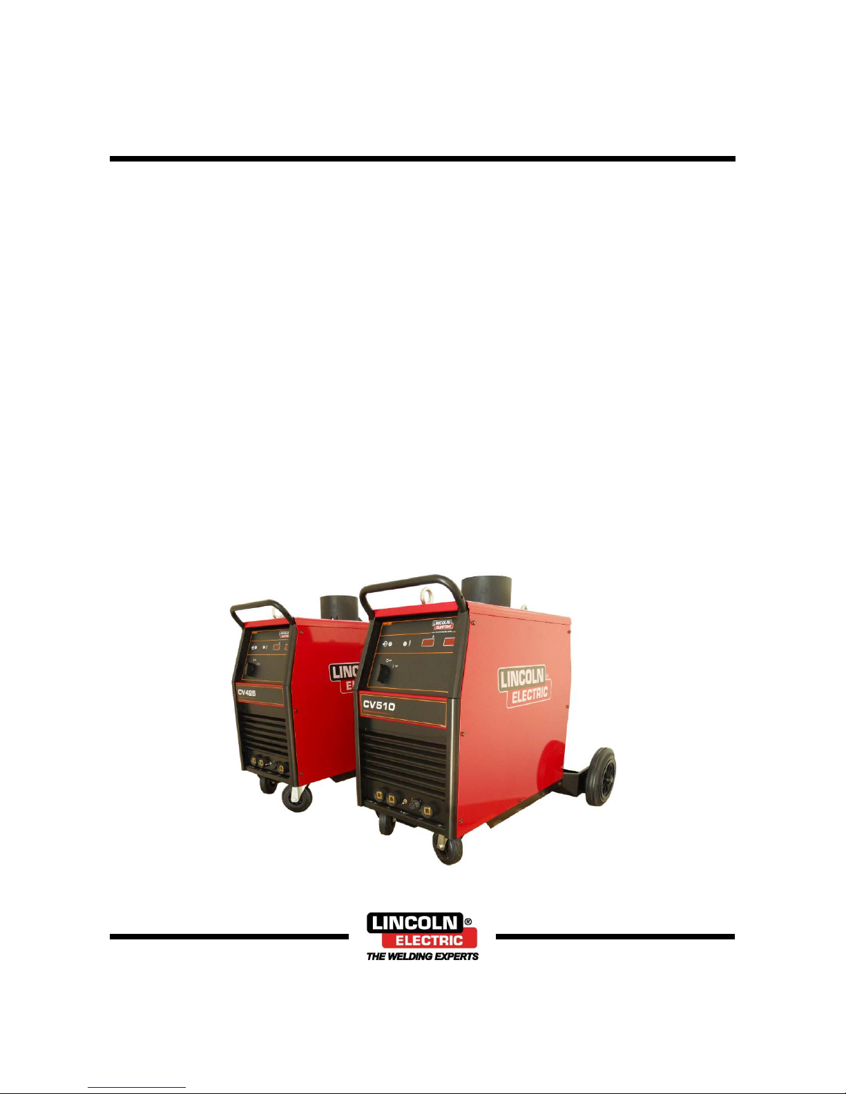
CV 425 & 510
OPERATOR’S MANUAL
ENGLISH
Lincoln Electric Bester Sp. z o.o.
ul. Jana III Sobieskiego 19A, 58-263 Bielawa, Poland
www.lincolnelectric.eu
Page 2

English I English
Declaration of conformity
Lincoln Electric Bester Sp. z o.o.
Declares that the welding machine:
K14080-2A CV 425 AIR 220/380/440V
K14081-2A CV 510 AIR 220/380/440V
conforms to the following directives:
2014/35/EU, 2014/30/EU
and has been designed in compliance with the
following standards:
EN 60974-1:2012, EN 60974-10:2014
20.04.2016
Piotr Spytek
Operations Director
Lincoln Electric Bester Sp. z o.o., ul. Jana III Sobieskiego 19A, 58-263 Bielawa, Poland
12/05
Page 3
English II English
12/05
THANKS! For having chosen the QUALITY of the Lincoln Electric products.
Please Examine Package and Equipment for Damage. Claims for material damaged in shipment must be notified
immediately to the dealer.
For future reference record in the table below your equipment identification information. Model Name, Code & Serial
Number can be found on the machine rating plate.
Model Name:
………………………………………………………………………………………………………………………………………….
Code & Serial Number:
………………………………………………………………….. …………………………………………………………………..
Date & Where Purchased
…………………………………………………………………. …………………………………………………………………..
ENGLISH INDEX
Safety .................................................................................................................................................................................. 1
Installation and Operator Instructions .................................................................................................................................. 2
Electromagnetic Compatibility (EMC) .................................................................................................................................. 5
Technical Specifications ...................................................................................................................................................... 6
WEEE ................................................................................................................................................................................. 7
Spare Parts ......................................................................................................................................................................... 7
Electrical Schematic ............................................................................................................................................................ 7
Accessories ......................................................................................................................................................................... 7
Page 4

English 1 English
Safety
11/04
WARNING
This equipment must be used by qualified personnel. Be sure that all installation, operation, maintenance and repair
procedures are performed only by qualified person. Read and understand this manual before operating this equipment.
Failure to follow the instructions in this manual could cause serious personal injury, loss of life, or damage to this
equipment. Read and understand the following explanations of the warning symbols. Lincoln Electric is not responsible
for damages caused by improper installation, improper care or abnormal operation.
WARNING: This symbol indicates that instructions must be followed to avoid serious personal injury,
loss of life, or damage to this equipment. Protect yourself and others from possible serious injury or
death.
READ AND UNDERSTAND INSTRUCTIONS: Read and understand this manual before operating this
equipment. Arc welding can be hazardous. Failure to follow the instructions in this manual could cause
serious personal injury, loss of life, or damage to this equipment.
ELECTRIC SHOCK CAN KILL: Welding equipment generates high voltages. Do not touch the
electrode, work clamp, or connected work pieces when this equipment is on. Insulate yourself from the
electrode, work clamp and connected work pieces.
ELECTRICALLY POWERED EQUIPMENT: Turn off input power using the disconnect switch at the
fuse box before working on this equipment. Ground this equipment in accordance with local electrical
regulations.
ELECTRICALLY POWERED EQUIPMENT: Regularly inspect the input, electrode, and work clamp
cables. If any insulation damage exists replace the cable immediately. Do not place the electrode holder
directly on the welding table or any other surface in contact with the work clamp to avoid the risk of
accidental arc ignition.
ELECTRIC AND MAGNETIC FIELDS MAY BE DANGEROUS: Electric current flowing through any
conductor creates electric and magnetic fields (EMF). EMF fields may interfere with some pacemakers
and welders having a pacemaker shall consult their physician before operating this equipment.
CE COMPLIANCE: This equipment complies with the European Community Directives.
ARTIFICIAL OPTICAL RADIATION: According with the requirements in 2006/25/EC Directive and EN
12198 Standard, the equipment is a category 2. It makes mandatory the adoption of Personal Protective
Equipment (PPE) having filter with a protection degree up to a maximum of 15, as required by EN169
Standard.
FUMES AND GASES CAN BE DANGEROUS: Welding may produce fumes and gases hazardous to
health. Avoid breathing these fumes and gases. To avoid these dangers the operator must use enough
ventilation or exhaust to keep fumes and gases away from the breathing zone.
ARC RAYS CAN BURN: Use a shield with the proper filter and cover plates to protect your eyes from
sparks and the rays of the arc when welding or observing. Use suitable clothing made from durable
flame-resistant material to protect you skin and that of your helpers. Protect other nearby personnel with
suitable, non-flammable screening and warn them not to watch the arc nor expose themselves to the
arc.
WELDING SPARKS CAN CAUSE FIRE OR EXPLOSION: Remove fire hazards from the welding area
and have a fire extinguisher readily available. Welding sparks and hot materials from the welding
process can easily go through small cracks and openings to adjacent areas. Do not weld on any tanks,
drums, containers, or material until the proper steps have been taken to insure that no flammable or
toxic vapors will be present. Never operate this equipment when flammable gases, vapors or liquid
combustibles are present.
Page 5

English 2 English
WELDED MATERIALS CAN BURN: Welding generates a large amount of heat. Hot surfaces and
materials in work area can cause serious burns. Use gloves and pliers when touching or moving
materials in the work area.
CYLINDER MAY EXPLODE IF DAMAGED: Use only compressed gas cylinders containing the correct
shielding gas for the process used and properly operating regulators designed for the gas and pressure
used. Always keep cylinders in an upright position securely chained to a fixed support. Do not move or
transport gas cylinders with the protection cap removed. Do not allow the electrode, electrode holder,
work clamp or any other electrically live part to touch a gas cylinder. Gas cylinders must be located
away from areas where they may be subjected to physical damage or the welding process including
sparks and heat sources.
SAFETY MARK: This equipment is suitable for supplying power for welding operations carried out in an
environment with increased hazard of electric shock.
The manufacturer reserves the right to make changes and/or improvements in design without upgrade at the same time
the operator’s manual.
Installation and Operator Instructions
Read this entire section before installation or operation
of the machine.
Location and Environment
This machine will operate in harsh environments.
However, it is important that simple preventative
measures are followed to assure long life and reliable
operation:
Do not place or operate this machine on a surface
with an incline greater than 15° from horizontal.
Do not use this machine for pipe thawing.
This machine must be located where there is free
circulation of clean air without restrictions for air
movement to and from the air vents. Do not cover
the machine with paper, cloth or rags when switched
on.
Dirt and dust that can be drawn into the machine
should be kept to a minimum.
This machine has a protection rating of IP23. Keep it
dry when possible and do not place it on wet ground
or in puddles.
Locate the machine away from radio controlled
machinery. Normal operation may adversely affect
the operation of nearby radio controlled machinery,
which may result in injury or equipment damage.
Read the section on electromagnetic compatibility in
this manual.
Do not operate in areas with an ambient temperature
greater than 40°C.
Duty cycle and Overheating
The duty cycle of a welding machine is the percentage of
time in a 10 minute cycle at which the welder can
operate the machine at rated welding current.
Example: 60% duty cycle
Welding for 6 minutes. Break for 4 minutes.
Excessive extension of the duty cycle will cause the
thermal protection circuit to activate.
Minutes or decrease
Duty Cycle
The machine is protected from overheating by a
temperature sensor.
Input Supply Connection
WARNING
Only a qualified electrician can connect the welding
machine to the supply network. Installation the outlet
plug to power lead and connecting the welding machine
had to be made in accordance with the appropriate
National Electrical Code and local regulations.
Check the input voltage, phase, and frequency supplied
to this machine before turning it on. Verify the
connection of grounding wires from the machine to the
input source. The allowable input voltages are 3x220V
50/60Hz, 3x380V 50/60Hz and 3x440V 50/60Hz
(3x440V: factory default). For more information about
input supply refer to the technical specification section of
this manual and to the rating plate of the machine.
If it is necessary to change the input voltage:
The input cable must be disconnected from the
mains supply and the machine switched OFF.
Remove the left side panel.
Reconnect X6 according to the diagram below:
220V 380V 440V
X6 X6 X6
Figure 1.
Page 6

English 3 English
Replace the left side panel.
Make sure that the amount of mains power available
from the input supply is adequate for normal operation of
the machine. The necessary delayed fuse (or circuit
breaker with "D" characteristic) and cable sizes are
indicated in the technical specification section of this
manual.
Output Connections
Refer to points [4], [5], [6] and [8] of the Figures 2.
Controls and Operational Features
1
2
3
5
4
7
6
8
9
Figure 2.
1. Power Switch ON/OFF (I/O): Controls the input
power to the machine. Be sure the power source is
connected to the mains supply before turning power
on ("I").
2. Power Indicator Light: After input power
is connected and the power switch is
turned on, this lamp will light up to
indicate the machine is ready to weld.
3. Thermal Overload Indicator: This lamp
will light up when the machine is
overheated and the output has been
turned off. This can occur if the ambient
temperature is above 40°C or the duty cycle of the
machine has been exceeded. Leave the machine on
to allow the internal components to cool, when the
lamp turns off normal operation is possible.
4. Low Inductance Negative Output Socket:
For connecting a work lead.
5. High Inductance Negative Output
Socket: For connecting a work lead.
6. Wire Feeder Receptacle: 14-pins
receptacle for wire feeder. Provides
connections for auxiliary power of wire
feeder.
7. Wire Feeder Voltmeter Switch: This
switch selects the polarity of the wire
feeder voltmeter, if so equipped. When the welding
torch is positive (MIG, Outershield and some
Innershield processes), set the switch to "+". When
the welding torch is negative (most Innershield
applications), set the switch to "-".
8. Positive Output Socket: Allows the
connection, with the power cable, to the
wire feeder.
9. Digital Welding Current and Voltage Meter: available
as an option (see "Accessories" chapter – Kit
K14082-1).
10
11
12
13
14
CV 425
10
11
12
13
14
CV 510
Figure 3.
10. Fuse: Use the 6,3A slow-blow fuse (see "Spare
Parts" section).
11. Hole Plug: For CO2 gas heater socket (see
"Accessories" chapter - K14009-1 CO2 Socket Kit).
12. Cooler Power Supply Socket: For supplying the
cooler unit only.
WARNING
The socket has an output of 230V, 2.5A and is protected
by the circuit breaker [13].
Page 7

English 4 English
13. Circuit Breaker: Protects the Cooler
Power Supply socket [12]. It shuts off the
power supply when the current exceeds
2.5A. Press it to restore the power supply.
14. Power Lead (5m): Connect the supply plug to the
existing input cable that is rated for the machine as
indicated in this manual, and conforms to all
applicable standards. This connection shall be
performed only by a qualified person.
Welding Cables Connections
Insert the plug of the work cable into the socket [4] or [5].
The other end of this cable connects to the work piece
with the work clamp.
Connect the wire feeder to the power source:
insert the positive welding cable into the output
socket [8].
insert the wire feeder control cable into the socket [6]
(see "Accessories" section, Source/wire feeder cable
K10347-PG-xM or K10347-PGW-xM).
Use the shortest possible cable lengths
Machine and Circuit Protection
The CV425 / CV510 is protected against overheating,
overload and accidental short-circuits
If the machine is overheated, the thermal protection
circuit will decrease the output current to 0. The thermal
protection indicator [3] will turn on. The thermal
protection circuit will turn on the output current again,
when the machine is cooled.
The CV425 / CV510 is also electronically protected
against overload and accidental short-circuit. The
overload and short-circuit protection circuit automatically
reduces the output current to a safe value when it
detects an overload.
Maintenance
WARNING
For any repair operations, modifications or
maintenances, it is recommended to contact the nearest
Technical Service Center or Lincoln Electric. Repairs
and modifications performed by unauthorized service or
personnel will cause, that the manufacturer’s warranty
will become null and void.
Any noticeable damage should be reported immediately
and repaired.
Routine maintenance (everyday)
Check condition of insulation and connections of the
work leads and insulation of power lead. If any
insulation damage exists replace the lead
immediately.
Remove the spatters from the welding gun nozzle.
Spatters could interfere with the shielding gas flow to
the arc.
Check the welding gun condition: replace it, if
necessary.
Check condition and operation of the cooling fan.
Keep clean its airflow slots.
Periodic maintenance (every 200 working hours but
at list once every year)
Perform the routine maintenance and, in addition:
Keep the machine clean. Using a dry (and low
pressure) airflow, remove the dust from the external
case and from the cabinet inside.
If it is required, clean and tighten all weld terminals.
The frequency of the maintenance operations may vary
in accordance with the working environment where the
machine is placed.
WARNING
Do not touch electrically live parts.
WARNING
Before the case of welding machine will be removed, the
welding machine had to be turned off and the power lead
had to be disconnected from mains socket.
WARNING
Mains supply network must be disconnected from the
machine before each maintenance and service. After
each repair, perform proper tests to ensure safety.
Transport
Figure 4.
To ensure safety transport it is to:
Lift only power source without gas cylinder , cooler
and wire feeder,
Screw down an eye bolt and apply load axially in 45
degree angle in accordance to the drawing.
Ensure equal length of lifting lines.
Page 8

English 5 English
Electromagnetic Compatibility (EMC)
11/04
This machine has been designed in accordance with all relevant directives and standards. However, it may still generate
electromagnetic disturbances that can affect other systems like telecommunications (telephone, radio, and television) or
other safety systems. These disturbances can cause safety problems in the affected systems. Read and understand this
section to eliminate or reduce the amount of electromagnetic disturbance generated by this machine..
This machine has been designed to operate in an industrial area. To operate in a domestic area it is
necessary to observe particular precautions to eliminate possible electromagnetic disturbances. The
operator must install and operate this equipment as described in this manual. If any electromagnetic
disturbances are detected the operator must put in place corrective actions to eliminate these disturbances
with, if necessary, assistance from Lincoln Electric.
Before installing the machine, the operator must check the work area for any devices that may malfunction because of
electromagnetic disturbances. Consider the following.
Input and output cables, control cables, and telephone cables that are in or adjacent to the work area and the
machine.
Radio and/or television transmitters and receivers. Computers or computer controlled equipment.
Safety and control equipment for industrial processes. Equipment for calibration and measurement.
Personal medical devices like pacemakers and hearing aids.
Check the electromagnetic immunity for equipment operating in or near the work area. The operator must be sure
that all equipment in the area is compatible. This may require additional protection measures.
The dimensions of the work area to consider will depend on the construction of the area and other activities that are
taking place.
Consider the following guidelines to reduce electromagnetic emissions from the machine.
Connect the machine to the input supply according to this manual. If disturbances occur if may be necessary to take
additional precautions such as filtering the input supply.
The output cables should be kept as short as possible and should be positioned together. If possible connect the
work piece to ground in order to reduce the electromagnetic emissions. The operator must check that connecting the
work piece to ground does not cause problems or unsafe operating conditions for personnel and equipment.
Shielding of cables in the work area can reduce electromagnetic emissions. This may be necessary for special
applications.
WARNING
The Class A equipment is not intended for use in residential locations where the electrical power is provided by the public
low-voltage supply system. There may be potential difficulties in ensuring electromagnetic compatibility in those
locations, due to conducted as well as radiated disturbances.
WARNING
This equipment complies with IEC 61000-3-12 provided that the short-circuit power Ssc is greater than or equal to:
CV 425: Ssc ≥ 9,5 MVA
CV 510: Ssc ≥ 14,3 MVA
at the interface point between the user’s supply and the public system. It is the responsibility of the installer or user of the
equipment to ensure, by consultation with the distribution network operator if necessary, that the equipment is connected
only to a supply with a short circuit power Ssc greater than or equal to data on the table above.
Page 9

English 6 English
Technical Specifications
NAME INDEX
CV 425 K14080-2A
CV 510 K14081-2A
INPUT
Input Voltage U
1
EMC Group / Class Frequency
CV 425
220/380/400V±10%
3 - phases
II / A 50 / 60 Hz
CV 510
Input Power at Rated Cycle Input Amperes I
1max
cos φ
CV 425
23 kVA @ 60% Duty Cycle 60 A 0,89
CV 510
29,2 kVA @ 60% Duty Cycle 75 A 0,89
RATED OUTPUT
Duty Cycle 40°C
(based on a 10 min. period)
Output Current Output Voltage
CV 425
60% 420 A 35 Vdc
100% 325 A 30,3 Vdc
CV 510
60% 500 A 39 Vdc
100% 385 A 33,3 Vdc
OUTPUT RANGE
Welding Current Range Open Circuit Voltage
CV 425
10 A ÷ 420 A 10 ÷ 39 Vdc
CV 510
10 A ÷ 500 A 10 ÷ 39 Vdc
RECOMMENDED INPUT CABLE AND FUSE SIZES
Fuse or Circuit Breaker Size Power Lead
220V 380V 440V
CV 425
D63 A D32 A D32 A 4 Conductor, 6 mm
2
CV 510
D63 A D32 A D32 A 4 Conductor, 10 mm
2
DIMENSION
Weight Height Width Length
CV 425
152 kg 880 mm 696 mm 1020 mm
CV 510
160 kg 880 mm 696 mm 1020 mm
Protection Rating
Operating Humidity
(t=20°C)
Operating Temperature Storage Temperature
IP23 ≤ 90 % from -10 ºC to +40 ºC from -25 ºC to +55 ºC
Page 10

English 7 English
WEEE
07/06
Spare Parts
12/05
Part list reading instructions
Do not use this part list for a machine if its code number is not listed. Contact the Lincoln Electric Service
Department for any code number not listed.
Use the illustration of assembly page and the table below to determine where the part is located for your particular
code machine.
Use only the parts marked "●" in the column under the heading number called for in the assembly page (# indicate
a change in this printing).
First, read the Part List reading instructions above then refer to the "Spare Part" manual supplied with the machine,
which contains a picture-descriptive part number cross-reference).
Electrical Schematic
Refer to the "Spare Parts" manual supplied with the machine.
Accessories
K10347-PG-xxM Source/wire feeder cable (gas). Available in 5, 10, 15m.
K10347-PGW-xxM Source/wire feeder cable (gas and water). Available in 5, 10 or 15m.
K14009-1 CO2 Socket Kit.
K14082-1 AV Meter Kit.
K14071-2 Grill Kit.
K14037-1 Cooler COOLARC 25.
English
Do not dispose of electrical equipment together with normal waste!
In observance of European Directive 2012/19/EC on Waste Electrical and Electronic Equipment
(WEEE) and its implementation in accordance with national law, electrical equipment that has reached
the end of its life must be collected separately and returned to an environmentally compatible recycling
facility. As the owner of the equipment, you should get information on approved collection systems
from our local representative.
By applying this European Directive you will protect the environment and human health!
 Loading...