

Lincoln Electric CV405-I Operator's Manual
IM1047
09/2003
Rev.3
CV405-I
OPERATOR’S MANUAL
MANUALE OPERATIVO
BEDIENUNGSANLEITUNG
MANUAL DE INSTRUCCIONES
MANUEL D'UTILISATION
BRUKSANVISNING OG DELELISTE
GEBRUIKSAANWIJZING
BRUKSANVISNING
LINCOLN ELECTRIC FRANCE
Avenue Franklin Roosevelt
76121 Le Grand Quevilly cedex
France
Tél : 02 32 11 40 40
Fax : 02 32 11 40 11
www.lincolnelectric.fr
2
Declaration of conformity
Dichiarazione di conformità
Konformitätserklärung
Declaración de conformidad
Déclaration de conformité
Samsvars erklæring
Verklaring van overeenstemming
Försäkran om överensstämmelse
Deklaracja zgodności
LINCOLN ELECTRIC FRANCE
Declares that the welding machine:
Dichiara che Il generatore per saldatura tipo:
Erklärt, daß die Bauart der Maschine:
Declara que el equipo de soldadura:
Déclare que le poste de soudage:
Bekrefter at denne sveisemaskin:
Verklaart dat de volgende lasmachine:
Försäkrar att svetsomriktaren:
CV405-I s/n
conforms to the following directives:
è conforme alle seguenti direttive:
den folgenden Bestimmungen entspricht:
es conforme con las siguientes directivas:
Est conforme aux directives suivantes:
er i samsvar med følgende direktiver:
Overeenkomt conform de volgende richtlijnen:
överensstämmer med följande direktiv:
73/23/CEE, 89/336/CEE
and has been designed in conformance with the following norms:
ed è stato progettato in conformità alle seguenti norme:
und in Übereinstimmung mit den nachstehenden Normen hergestellt wurde:
y ha sido diseñado de acuerdo con las siguientes normas:
et qu'il a été conçu en conformité avec les normes:
og er produsert og testet iht. følgende standarder:
en is ontworpen conform de volgende normen:
och att den konstruerats i överensstämmelse med följande standarder:
EN 50199, EN 60974-1
LINCOLN ELECTRIC FRANCE, Avenue Franklin Roosevelt, 76121 Le Grand Quevilly cedex, France

3
ENGLISH INDEX
Safety .............................................................................................................................................................................. 4
Installation and Operator Instructions .............................................................................................................................. 5
Electromagnetic Compatibility (EMC) ..............................................................................................................................7
CV405-I Technical Specifications ....................................................................................................................................8
INDICE ITALIANO
Sicurezza......................................................................................................................................................................... 9
Installazione e Istruzioni Operative................................................................................................................................ 10
Compatibilità Elettromagnetica (EMC)........................................................................................................................... 12
CV405-I Specifiche Tecniche ........................................................................................................................................12
INHALTSVERZEICHNIS DEUTSCH
Sicherheitsmaßnahmen / Unfallschutz ..........................................................................................................................14
Installation und Bedienungshinweise............................................................................................................................. 15
Elektromagnetische Verträglichkeit (EMC) .................................................................................................................... 18
CV405-I Technische Daten............................................................................................................................................ 18
INDICE ESPAÑOL
Seguridad ...................................................................................................................................................................... 19
Instalación e Instrucciones de Funcionamiento ............................................................................................................. 20
Compatibilidad Electromagnética (EMC)....................................................................................................................... 22
CV405-I Especificaciones Técnicas .............................................................................................................................. 23
INDEX
Sécurité .........................................................................................................................................................................24
Installation et Instructions d'Utilisation ........................................................................................................................... 25
Compatibilité Electromagnétique (CEM)........................................................................................................................ 27
CV405-I Caractéristiques Techniques ........................................................................................................................... 28
INNHOLD
Sikkerhetsregler............................................................................................................................................................. 29
Installasjon og brukerveiledning ....................................................................................................................................30
Elektromagnetisk Kompatibilitet (EMC) .........................................................................................................................32
CV 405-I Tekniske spesifikasjoner ................................................................................................................................ 32
NEDERLANDSE INDEX
WAARSCHUWING........................................................................................................................................................ 34
Installatie en Bediening.................................................................................................................................................. 35
Elektromagnetische Compatibiliteit (EMC) ....................................................................................................................37
CV405-I Technische Specificatie................................................................................................................................... 38
INNEHÅLL
Säkerhetsanvisningar .................................................................................................................................................... 39
Installations- och handhavandeinstruktioner.................................................................................................................. 40
Elektromagnetisk kompatibilitet (EMC).......................................................................................................................... 42
CV05-I Tekniska Specifikationer.................................................................................................................................... 42
Spare Parts, Pièces de Rechange,Parti di Ricambio, Ersatzteile, Lista de Piezas de Recambio, Deleliste, Reserve
Onderdelen, Reservdelar .............................................................................................................................................. 44
Electrical Schematic, Schéma Electrique, Schema Elettrico, Elektrische Schaltpläne, Esquema Eléctrico, Elektrisk
Skjema, Elektrisch Schema, Elektriskt kopplingsschema.............................................................................................. 53
Accessories, Accessoires, Accessori, Zubehör, Accesorios, Tilleggsutstyr, Accessores, Tillbehör............................... 54
4
Safety
WARNING
This equipment must be used by qualified personnel. Be sure that all installation, operation, maintenance and repair
procedures are performed only by qualified individuals. Read and understand this manual before operating this
equipment. Failure to follow the instructions in this manual could cause serious personal injury, loss of life, or damage to
this equipment. Read and understand the following explanations of the warning symbols. Lincoln Electric is not
responsible for damages caused by improper installation, improper care or abnormal operation.
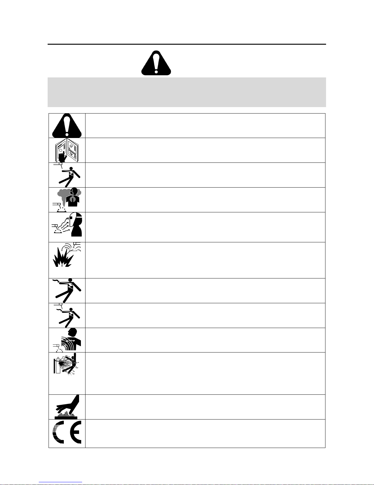
WARNING: This symbol indicates that instructions must be followed to avoid serious personal injury,
loss of life, or damage to this equipment. Protect yourself and others from possible serious injury or
death.
READ AND UNDERSTAND INSTRUCTIONS: Read and understand this manual before operating
this equipment. Arc welding can be hazardous. Failure to follow the instructions in this manual could
cause serious personal injury, loss of life, or damage to this equipment.
ELECTRIC SHOCK CAN KILL: Welding equipment generates high voltages. Do not touch the
electrode, work clamp, or connected work pieces when this equipment is on. Insulate yourself from
the electrode, work clamp, and connected work pieces.
FUMES AND GASES CAN BE DANGEROUS: Welding may produce fumes and gases hazardous to
health. Avoid breathing these fumes and gases. To avoid these dangers the operator must use
enough ventilation or exhaust to keep fumes and gases away from the breathing zone.
ARC RAYS CAN BURN: Use a shield with the proper filter and cover plates to protect your eyes from
sparks and the rays of the arc when welding or observing. Use suitable clothing made from durable
flame-resistant material to protect you skin and that of your helpers. Protect other nearby personnel
with suitable, non-flammable screening and warn them not to watch the arc nor expose themselves to
the arc.
WELDING SPARKS CAN CAUSE FIRE OR EXPLOSION: Remove fire hazards from the welding
area and have a fire extinguisher readily available. Welding sparks and hot materials from the welding
process can easily go through small cracks and openings to adjacent areas. Do not weld on any
tanks, drums, containers, or material until the proper steps have been taken to insure that no
flammable or toxic vapors will be present. Never operate this equipment when flammable gases,
vapors or liquid combustibles are present.
ELECTRICALLY POWERED EQUIPMENT: Turn off input power using the disconnect switch at the
fuse box before working on this equipment. Ground this equipment in accordance with local electrical
regulations.
ELECTRICALLY POWERED EQUIPMENT: Regularly inspect the input, electrode, and work clamp
cables. If any insulation damage exists replace the cable immediately. Do not place the electrode
holder directly on the welding table or any other surface in contact with the work clamp to avoid the
risk of accidental arc ignition.
ELECTRIC AND MAGNETIC FIELDS MAY BE DANGEROUS: Electric current flowing through any
conductor creates electric and magnetic fields (EMF). EMF fields may interfere with some
pacemakers, and welders having a pacemaker should consult their physician before operating this
equipment.
CYLINDER MAY EXPLODE IF DAMAGED: Use only compressed gas cylinders containing the
correct shielding gas for the process used and properly operating regulators designed for the gas and
pressure used. Always keep cylinders in an upright position securely chained to a fixed support. Do
not move or transport gas cylinders with the protection cap removed. Do not allow the electrode,
electrode holder, work clamp or any other electrically live part to touch a gas cylinder. Gas cylinders
must be located away from areas where they may be subjected to physical damage or the welding
process including sparks and heat sources.
WELDED MATERIALS CAN BURN: Welding generates a large amount of heat. Hot surfaces and
materials in work area can cause serious burns. Use gloves and pliers when touching or moving
materials in the work area.
CE COMPLIANCE: This equipment complies to the European Communities directives.
5
SAFETY MARK: This equipment is suitable for supplying power for welding operations carried out in
an environment with increased hazard of electric shock.
Installation and Operator Instructions
Read this entire section before installation or operation
of the machine.
Location and Environment
This machine will operate in harsh environments.
However, it is important that simple preventative
measures are followed to assure long life and reliable
operation.
• Do not place or operate this machine on a surface
with an incline greater than 15° from horizontal.
• This machine must be located where there is free
circulation of clean air without restrictions for air
movement to and from the air vents. Do not cover
the machine with paper, cloth or rags when
switched on.
• Dirt and dust that can be drawn into the machine
should be kept to a minimum.
• This machine has a protection rating of IP21. Keep
it dry when possible and do not place it on wet
ground or in puddles.
• Locate the machine away from radio controlled
machinery. Normal operation may adversely affect
the operation of nearby radio controlled machinery,
which may result in injury or equipment damage.
Read the section on electromagnetic compatibility in
this manual.
• Do not operate in areas with an ambient
temperature greater than 40°C.
Input Supply Connection
Check the input voltage, phase, and frequency supplied
to this machine before turning it on. The allowable input
voltage is indicated in the technical specification section
of this manual and on the rating plate of the machine.
Verify the connection of grounding wires from the
machine to the input source.
The frame of this machine must be grounded. A ground
terminal located on the base of the generator is provided
for this purpose.
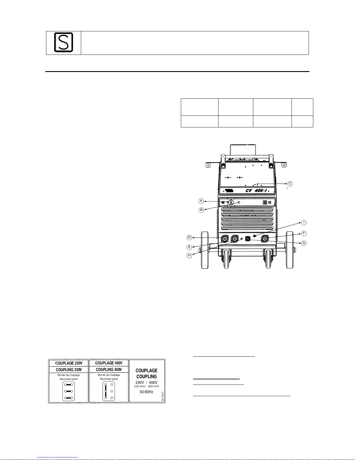
This machine is factory 3ph-400V connected. To
connect it in 3ph-230V, remove the left case panel of the
machine to have access to the input reconnect panel.
Modify the connections according to the connection
diagram located on the inside of the case side and
shown below.
Recommended input wire and fuse
sizes
Input voltage/
frequency
Input circuit
fuse
(FM = 60%)
Recommended
input wire size
Fuse
230 V / 50 Hz
400 V / 50 Hz
60A
34A
4x10 mm
2
4x10 mm
2
100A
60A
Operation
General description :
The CV405-I is a constant voltage DC power source
designed for the GMAW and FCAW processes. It is
available with :
• 42 VAC/10 amp auxiliary power for the wire feeder.
• 230 VAC/ 3.5 amp auxiliary power for water cooler.
For a quick and easy handling within the welding area, it
is factory mounted on a built-in undercarriage equipped
with a platform for a gas cylinder. Recommended wire
feeders: LF30/31, LN-25, LN-27.
Controls on the case front
A. ON/OFF power switch (O/I) : It controls the input
power to the machine. Be sure the power source is
connected to the mains supply before turning power
on ( "I").
B. Power indicator light : Indicates the power is on.
C. Thermal indicator light : It indicates the machine is
overloaded or if cooling is not sufficient.
D. High inductance negative output connection : The
high inductance connection is more suitable for short
arc welding heavier weldments or when using 75%
Argon / 25% CO2 shielding gas. This connection
produces a softer arc and a flatter bead with more
wash-in than the low inductance connection. A spray
6
type transfer is possible with either connection.
E. Low inductance negative connection : The low
inductance connection is typically used for short arc
welding of mild steel, particularly on thin materials or
when using CO2 shielding gas.
F. Positive output connection : Allows the connection of
the power cable to the wire feeder.
G. Wire feeder receptacle : 14-pin MS style receptacle
for wire feeder. Provides connections for auxiliary
power, contactor closure, wire feeder voltmeter,
sense lead and ground.
H. 42 Volts circuit breaker : Protects the 42 volt circuit
in the wire feeder receptacle form overloads and
shorts.
I. Wire feeder voltmeter switch : This switch selects the
polarity of the wire feeder voltmeter, if so equipped.
When welding electrode positive (MIG, Outershield
and some Innershield processes), set the switch to
"+". When welding electrode negative (most
Innershield applications), set the switch to "-".
NOTE : The rating plate is located on the rear panel of
the machine.
Back panel
J. Cable clamp for input cables.
K. Circuit breaker : Protects the 230V auxiliary circuit
from overloads and shorts. If this breaker opens, the
CV405-I will work normally ; however, equipment
powered by the 230V receptacle will not work.
L. 230V 3.5A AC receptacle : For connection of water
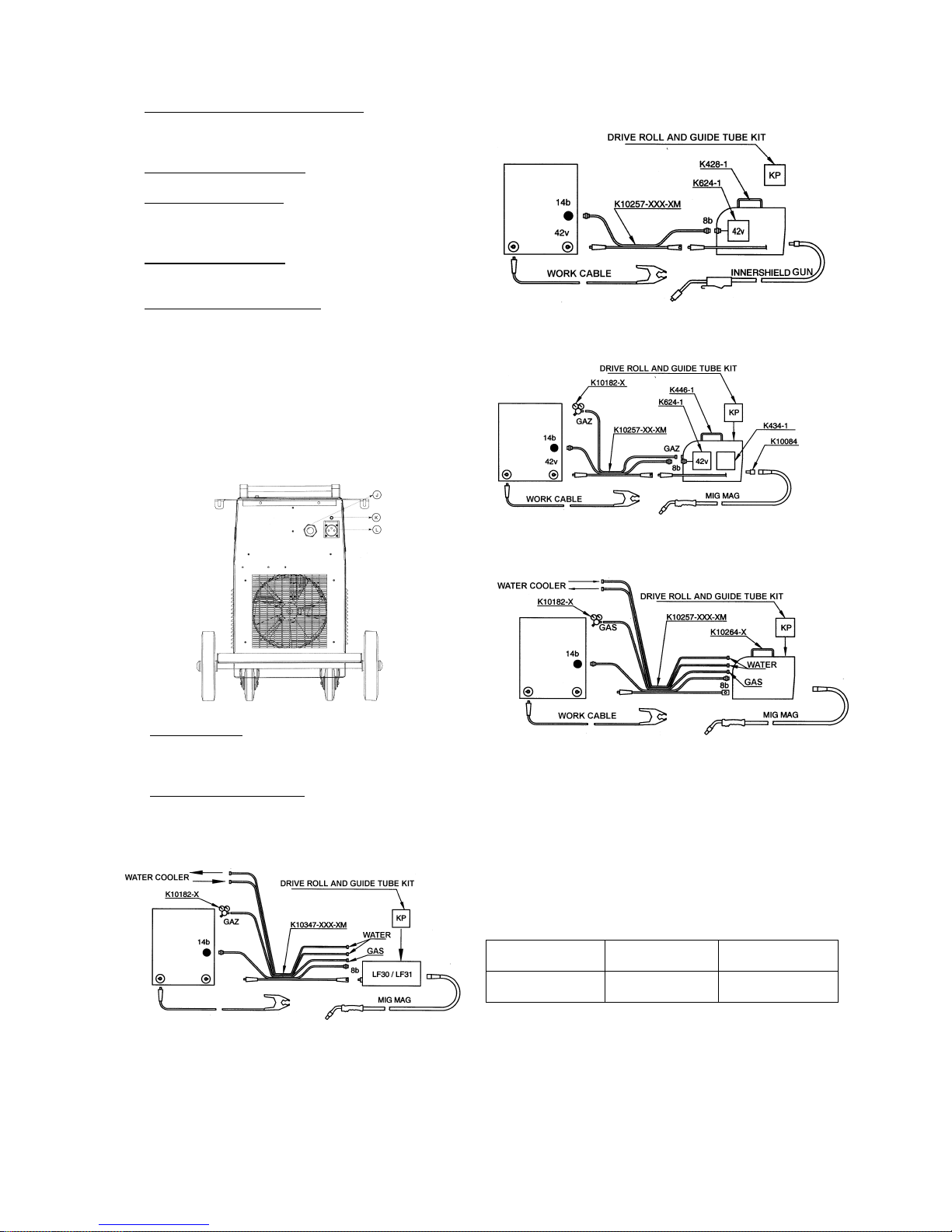
cooler or other equipment.nection diagrams
LF30 & LF31
LN25
a) K428-1
b) K446-1
LN27
Output Connections
Output cables must have Twist-mate plugs for
connection to the CV405-I. Use the shortest possible
cable lengths. Connect the positive output lead to the
terminal marked (+). The negative output lead can be
hooked to either the low inductance terminal or the high
inductance terminal.
Cable sizes for combined lengths of electrode and work
cable :
Machine
size
Lengths up to
45m
Lengths from 45 to
60m
300A @ 100%
or 400 @ à 60%
70 mm² 95 mm²
Machine and Circuit Protection
The CV405-I is thermostatically protected against
overloads or insufficient cooling. If the machine is
overloaded, the thermostat will open, thermal protection
indicator light will turn on and the output current will be 0.
The fan will continue to run and auxiliary power will still
be available. The thermostat will remain open until the
 Loading...