

Page 1
ACN 000 040 308
THE LINCOLN ELECTRIC COMPANY
(AUSTRALIA) PTY. LTD.
A.C.N. 000 040 308
SYDNEY. AUSTRALIA
A Subsidiary of
THE LINCOLN ELECTRIC CO. U.S.A.
Associated Subsidiaries in Australasia, Europe, North and South America.
THE WORLD’S LEADER IN WELDING AND CUTTING PRODUCTS
SAFETY DEPENDS ON YOU
Lincoln Electric welders are designed and built with safety in mind. However, your overall safety can be increased by
proper installation . . . and thoughtful operation on your part. Read and observe the general safety precautions on
page 2 and follow specific installation and operating instructions included in this manual.
Most importantly, think before you act and be careful.
IMA 574B
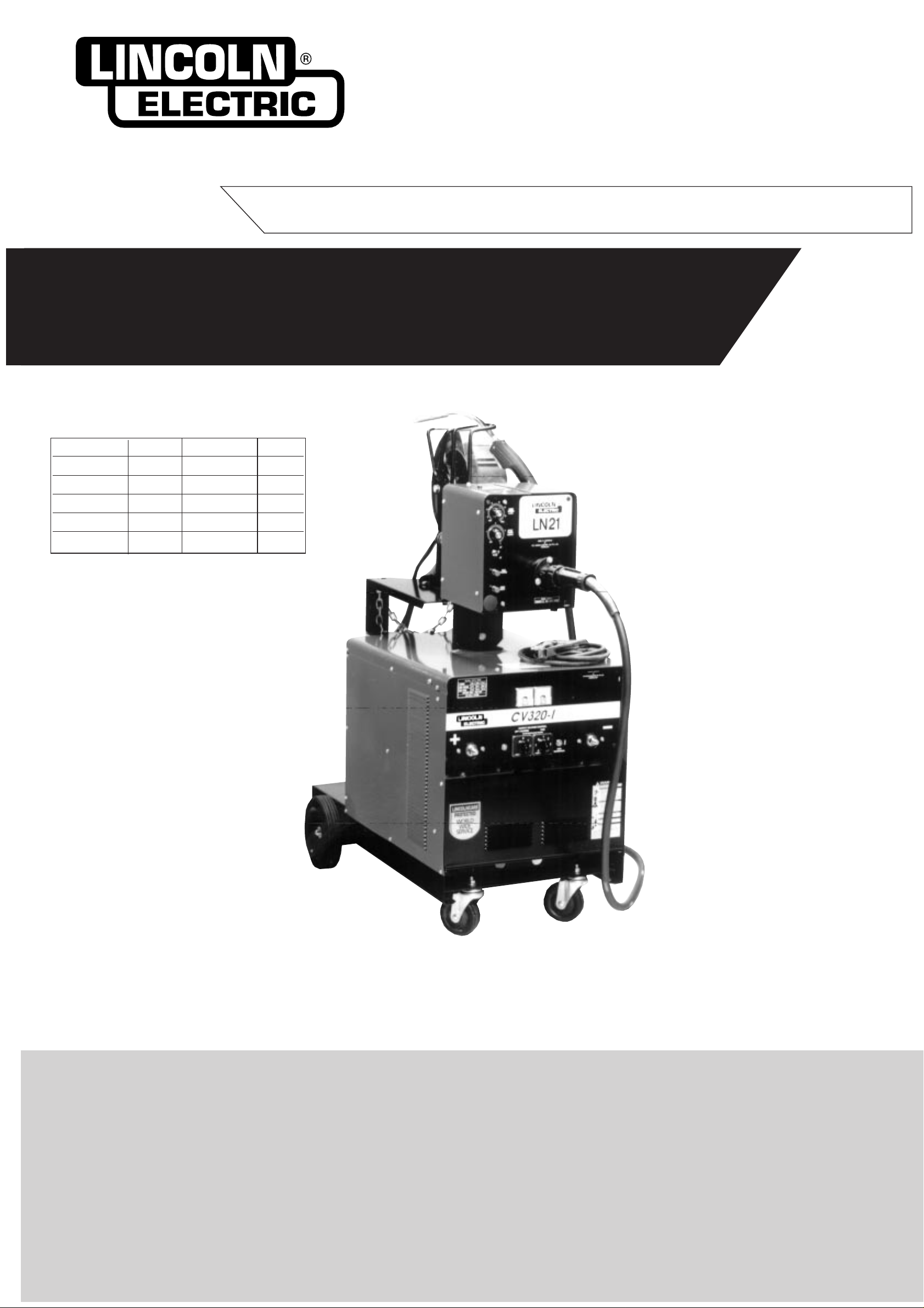
OPERATING MANUAL
Part No. Code Desc Volts
KA1392 1447 CV320-I 415
KA1392-1 1473 CV320-I 380
KA1392 1509 CV320-I 415
KA1392-1 1510 CV320-I 380
KA1392 1535 CV320-I 415
This manual applies to
CV320-I
Semi automatic arc welding machine
Page 2
Page 2 CV320-I IMA 574B
PROTECT YOURSELF AND OTHERS FROM POSSIBLE SERIOUS INJURY OR DEATH. READ AND UNDERSTAND
BOTH THE SPECIFIC INFORMATION GIVEN IN THE OPERATING MANUAL FOR THE WELDER AND/OR OTHER
EQUIPMENT TO BE USED AS WELL AS THE FOLLOWING GENERAL INFORMATION.
ARC WELDING SAFETY PRECAUTIONS
1.a. The electrode and work (or ground) circuits are
electrically “hot” when the welder is on. Do not touch
these “hot” parts with your bare skin or wet clothing.
Wear dry, hole-free gloves to insulate hands.
b. In semi-automatic and automatic wire welding, the
electrode, electrode reel, welding head and nozzle or
semi-automatic welding gun are also electrically “hot”.
c. Insulate yourself from work and ground using dry
insulation. When welding in damp locations, on metal
framework such as floors, gratings or scaffolds, and
when in positions such as sitting or Lying, make certain
the insulation is large enough to cover your full area of
physical contact with work and ground.
d. Always be sure the work cable makes a good electrical
connection with the metal being welded. The
connection should be as close as possible to the area
being welded.
e. Ground the work or metal to be welded to a good
electrical (earth) ground.
f. Maintain the electrode holder, work clamp, welding
cable and welding machine in good, safe operating
condition. Replace damaged insulation.
g. Never dip the electrode holder in water for cooling.
h. Never simultaneously touch electrically “hot” parts of
electrode holders connected to two welders because
voltage between the two can be the total of the open
circuit voltage of both welders.
i. When working above floor level, protect yourself from
a fall should you get a shock.
j. Also see items 4c and 6.
2.a. Welding may produce fumes and gases hazardous to
health. Avoid breathing these fumes and gases. When
welding, keep your head out of the fume. Use enough
ventilation and/or exhaust at the arc to keep fumes and
gases away from the breathing zone. When welding
on galvanized, lead or cadmium plated steel and other
metals which produce toxic fumes, even greater care
must be taken.
b. Do not weld in locations near chlorinated hydrocarbon
vapours coming from degreasing, cleaning or spraying
operations. The heat and rays of the arc can react with
solvent vapours to form phosgene, a highly toxic gas,
and other irritating products.
c. Shielding gases used for arc welding can displace air
and cause injury or death. Always use enough
ventilation, especially in confined areas, to ensure
breathing air is safe.
d. Read and understand the manufacturer ’s instructions
for this equipment and the consumables to be used,
including the material safety data sheet (MSDS) and
follow your employer’s safety practices.
e. Also see Item 7b.
3. a. Use a shield with the proper filter and cover plates to
protect your eyes from sparks and the rays of the arc
when welding or observing open arc welding.
Headshield and filter lens should conform to AS 1674.21990 standards.
b. Use suitable clothing made from durable flame
resistant material to protect your skin and that of your
helpers from the arc rays.
c. Protect other nearby personnel with suitable non
flammable screening and/or warn them not to watch the
arc or expose themselves to the arc rays or to hot
spatter or metal.
4.a. Remove fire hazards from the welding area. If this is not
possible, cover them to prevent the welding sparks
from starting a fire. Remember that welding sparks and
hot materials from welding can easily go through small
cracks and openings to adjacent areas. Have a fire
extinguisher readily available.
b. Where compressed gases are to be used at the job
site, special precautions should be used to prevent
hazardous situations. Refer to AS1674 Parts 1 & 2
“Safety in Welding and Allied Processes”, WTIA
Technical Note 7 “Health and Safety in Welding” and
the operating information for the equipment being used.
c. When not welding, make certain no part of the
electrode circuit is touching the work or ground.
Accidental contact can cause overheating and create a
fire hazard.
d. Do not heat, cut or weld tanks, drums or containers until
the proper steps have been taken to insure that such
procedures will not cause flammable or toxic vapours
from substances inside. These can cause an explosion
even though the vessel has been “cleaned”. For
information purchase AS 1674-1990.
e. Vent hollow castings or containers before heating,
cutting or welding. They may explode.
f. Sparks and spatter are thrown from the welding arc.
Wear oil free protective garments such as leather
gloves, heavy shirt, cuffless trousers, high shoes and a
cap over your hair. Wear ear plugs when welding out of
position or in confined places. Always wear safety
glasses with side shields when in a welding area.
g. Connect the work cable to the work as close to the
welding area as possible. Work cables connected to the
building framework or other locations away from the
welding area increase the possibility of the welding
current passing through lifting chains, crane cables or
other alternate circuits. This can create fire hazards or
overheat lifting chains or cables until they fail.
h. Also see Item 7c.
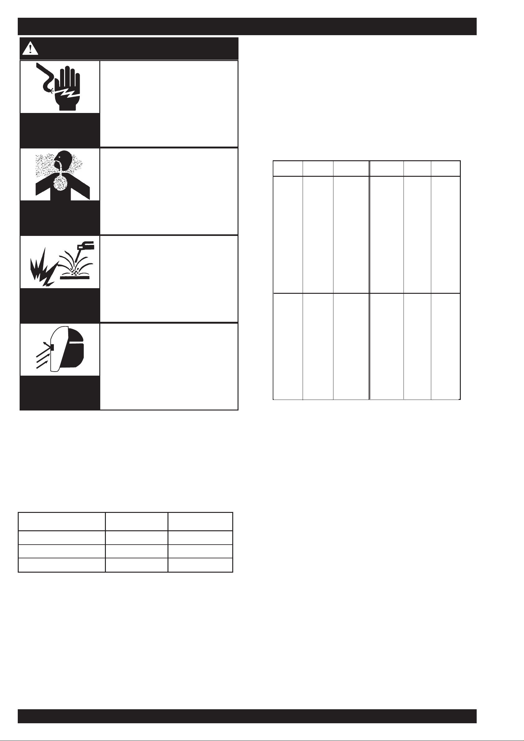
ELECTRIC SHOCK can kill
FUMES AND GASES
can be dangerous
ARC RAYS can burn
WELDING SPARKS can
cause fire or explosion
Page 3
IMA 574B CV320-I Page 3
5. a. Use only compressed gas cylinders containing the
correct shielding gas for the process used and
properly operating regulators, designed for the gas
and pressure used. All hoses, fittings, etc. should be
suitable for the application and maintained in good
condition.
b. Always keep cylinders in an upright position and
securely chained to an undercarriage or fixed
support.
c. Cylinders should be located :
• Away from areas where they may be struck or
subjected to physical damage.
• A safe distance from arc welding or cutting
operations and any other source of heat, sparks or
flame.
d. Never allow the electrode, electrode holder, or any
other electrically “hot” parts to touch a cylinder.
e. Keep your head and face away from the cylinder
valve outlet when opening the cylinder valve.
f. Valve protection caps should always be in place and
hand-tight except when the cylinder is in use or
connected for use.
g. Read and follow the instructions on compressed gas
cylinders and associated equipment, and AS 2030
Parts 1 & 2.
6. a. Turn off input power using the disconnect switch at
the fuse box before working on the equipment.
b. Install equipment in accordance with the SAA Wiring
Rules, all local codes and the manufacturer’s
recommendations.
c. Ground the equipment in accordance with the SAA
Wiring Rules and the manufacturer’s
recommendations.
7. a. Turn the engine off before troubleshooting and
maintenance work unless the maintenance
work requires it to be running.
b. Operate engines in open, well ventilated areas
or vent the engine exhaust fumes outdoors.
c.Do not add fuel near an open flame, welding
arc or when the engine is running. Stop the
engine and allow it to cool before refuelling to
prevent spilled fuel from vaporizing on contact
with hot engine parts and igniting. Do not spill
fuel when filling tank. If fuel is spilled, wipe it up
and do not start engine until fumes have been
eliminated.
d.Keep all equipment, safety guards, covers
and devices in position and in good repair.
Keep hands, hair, clothing and tools away
from V-belts, gears, fans and all other
moving parts when starting, operating or
repairing equipment.
e. In some cases it may be necessary to remove
safety guards to perform required
maintenance. Remove guards only when
necessary and replace them when the
maintenance requiring their removal is
complete. Always use the greatest care when
working near moving parts.
f. Do not put your hands near the engine fan.
Do not attempt to override the governor or
idler by pushing on the throttle control rods
while the engine is running.
g.To prevent accidentally starting petrol engines
while turning the engine or welding generator
during maintenance work, disconnect the
spark plug wires, distributor cap or magneto
wire as appropriate.
h.To avoid scalding do not remove the radiator
pressure cap when the engine is hot.
CYLINDER may explode if
damaged
FOR ELECTRICALLY
powered equipment
FOR ENGINE powered
equipment
HAVE ALL INSTALLATIONS, OPERATION, MAINTENANCE AND REPAIR WORK PERFORMED BY QUALIFIED PEOPLE
HOW TO ORDER REPLACEMENT PARTS
To ensure that you receive the correct replacement part the following procedure should be followed:
1. Quote Serial Number and Code Number.
2. Quote the Description, Item Number and Parts List Number of the desired part. When ordering parts for items
carrying brand names of other companies, such as fan motors, drive shafts, etc., be sure to include the other
company’s name and part number and other relevant information.
3. Should the primary cord be damaged, a special cord is required, and is available from Lincoln.
4. Parts should be ordered from Lincoln’s nearest authorised Field Service Shop. (The “Lincoln
Service Directory” listing these shops geographically is available on request.)
NOTE: “Hardware” in the Lincoln Parts Lists are not Lincoln stock items but can be obtained via the Field Service Shop network.
Component parts of assemblies such as stator coils or armature coils, etc., which require electrical testing or locating fixtures are
not considered replaceable items. This is to ensure that the customer receives parts which will keep the welder in the best
operating condition.
For more detailed information it is strongly recommended that you purchase a copy of “Safety in Welding and Cutting - ANSI
Standard Z 49.1” and WTIA Technical Note 7. All WTIA publications and ANSI/AWS Standards are available from the Welding
Technology Institute of Australia, P.O. Box 6165, Silverwater NSW 2128. For copies of various Australian Standards contact your
local S.A.A. office.
Page 4

Page 4 CV320-I IMA 574B
All welders should follow safe practices that minimize their
exposure to electric and magnetic fields (EMF).
For welders wearing implanted pacemakers, safe welding
practices are particularly important and additional procedures
should be followed by those who have decided to continue to
weld. (Hopefully in keeping with a doctor’s advice).
The following procedures will not eliminate exposure to EMF or
the possibility of arc welding having an effect on a pacemaker,
however if followed, they will significantly reduce exposure to
electric and magnetic fields. Electric and magnetic fields are
created any time electric current flows through a conductor,
however it is not clear whether such exposure affects ones health.
Some researchers have reported that exposure to EMF may
cause leukemia or other illnesses. These claims originally arose in
relation to high voltage electric power lines and are very much in
dispute in the medical and scientific arena, however the best
advice is to minimise your exposure to EMF to protect your health
should doctors eventually decide there is a risk.
There are four fundamental fact about EMF:
• With direct current (DC), the field strength is relatively
constant and does not change.
• With alternating current (AC), the field strength constantly
changes.
• The greater the current flow, i.e. the higher the amps, the
stronger the field created by the current
• The closer the conductor or electrical device is to the body,
the greater the exposure to the field.
Minimising Exposure
All welders should use the following procedures to minimise EMF
exposure.
• Route electrode or gun and work cables together. Secure
them with tape if possible.
• Never coil the electrode lead around your body.
• Do not place your body between the electrode and work
cables. If your electrode cable is on your right side the work
cable should also be on your right side.
• Connect the work cable to the work piece as close as possible
to the area being welded. (This is also a good practice to
eliminate a common problem on welding - a poor work
connection).
• Do not work next to the welding power source.
Welders with Pacemakers
There is no question that the fields in arc welding can interfere
with a pacemakers function. Generally the interference does not
permanently damage the pacemaker. Once the wearer leaves the
arc welding environment or stops welding, the pacemaker returns
to normal functioning. The welding arc has little or no effect on the
operation of some pacemakers, especially designs that are bipolar or designed to filter out such interference.
For a welder or anyone working around electrical equipment the
selection of a pacemaker is very important. Get a doctor’s advice
about which pacemaker is the least sensitive to interference from
welding while still being medically suitable.
In addition to the normal safety precautions, the following
additional procedures should be adopted by welders with
pacemakers.
• Use gas welding when the application is suitable.
• Use the lowest current setting appropriate for the application.
Do not exceed 400 amps. Low current (75-200 amps) direct
current (DC) welding should be used if arc welding is
necessary. Do not TIG weld with high frequency.
• Do not use repeated, short welds. Wait about ten seconds
between stopping one weld and starting the next. When
having difficulty starting an electrode, do not re-strike the rod
repeatedly.
• If you feel light headed, dizzy or faint, immediately stop
welding. Lay the electrode holder down so that it does not
contact the work and move away from any welding being
performed. Arrange your work in advance so that, if you
become dizzy and drop the electrode holder, the electrode
holder will not fall on your body or strike the work.
• Do not work on a ladder or other elevated position or in a
cramped, confined place.
• Do not work alone. Work only in the presence of an individual
who understands these precautions and the possible effect
welding may have on your pacemaker.
• Do not work near spot welding equipment.
• If you have a pacemaker and wish to continue arc welding,
discuss this an any other questions you may have with your
physician and follow his or her advice. The doctor may wish to
contact the pacemaker manufacturer for a recommendation.
As mentioned before, the design of the pacemaker
significantly affects the degree to which it is subject to
interference from a welding circuit. Do not rely on the fact that
you know another welder with a pacemaker who has welded
for years without experiencing a problem. That welder and his
or her pacemaker may be quite different from you and your
pacemaker.
WELDING, EMF AND PACEMAKERS
Page 5

IMA 574B CV320-I Page 5
INSTRUCTIONS FOR ELECTROMAGNETIC COMPATIBILITY
Conformance
Products displaying the C-Tick mark are in conformity with
Australian/New Zealand requirements for the Electromagnetic
Compatibility (EMC). They are:
• manufactured in conformity with Australian/New Zealand
Standard (Emission):- AS/NZS 3652 ‘Electromagnetic
Compatibility - Arc Welding Equipment’ (identical to and
reproduced from, British Standard EN 50199).
• for using with other Lincoln Electric/LiquidArc equipment.
• designed for industrial and professional use.
Introduction
All electrical equipment generates small amounts of
electromagnetic emission. Electrical emission may be transmitted
through power lines or radiated through space, similar to a radio
transmitter. When emissions are received by other equipment,
electrical interference may result. Electrical emissions may effect
many kinds of electrical equipment; other near by welding
equipment, radio and TV reception, numerical controlled
machines, telephone systems, computers, etc. Be aware that
interference may result and extra precautions may be required
when a welding power source is used in a domestic
establishment.
Installation and Use
The purchaser/user is responsible for installing and using the
welding equipment according to the manufacturer’s instructions. If
electromagnetic disturbances are detected then it shall be the
responsibility of the purchaser/user of the welding equipment to
resolve the situation with the technical assistance of the
manufacturer. In some cases this remedial action may be as
simple as earthing (grounding) the welding circuit (see note
below). In other cases it could involve constructing an
electromagnetic screen enclosing the power source and the work
complete with associated input filters. In all cases electromagnetic
disturbances must be reduced to the point where they are no
longer troublesome.
NOTE: The welding circuit may or may not be earthed for safety
reasons according to national codes. Changing the earthing
arrangements should only be authorised by a person who is
competent to assess whether the changes increase the risk of
injury, eg. by allowing parallel welding current return paths which
may damage the earth circuits of other equipment.
Assessment of Area
Before installing welding equipment the purchaser/user shall make
an assessment of potential problems in the surrounding area.
The following shall be taken into account:
a. Other supply cables, control cables, signalling and telephone
cables; above, below and adjacent to the welding equipment;
b. Radio and television transmitters and receivers;
c. Computer and other control equipment;
d. Safety critical safety equipment, eg. guarding of industrial
equipment;
e. The health of people around, eg. the use of pacemakers and
hearing aids;;
f. Equipment used for calibration or measurement;
g. The immunity of other equipment in the environment. The
purchaser/user shall ensure that other equipment being used
in the environment is compatible. This may require additional
protection measures;
h. The time of the day that welding or other activities are to be
carried out.
The size of the surrounding area to be considered will depend on the
structure of the building and other activities that are taking place. The
surrounding area may extend beyond the boundaries of the premises.
Methods of Reducing Emissions
Mains Supply
Welding equipment should be connected to the mains supply
according to the manufacturers recommendations.If interference
occurs, it may be necessary to take additional precautions such as
filtering the mains supply. Consideration should be given to
shielding the supply cable of permanently installed welding
equipment, in metallic conduit or equivalent. Shielding should be
electrically continuous throughout its length. The shielding should
be connected to the welding power source so that good electrical
contact is maintained between the conduit and the welding power
source enclosure.
Maintenance of the Welding Equipment
The welding equipment should be routinely maintained according
to the manufacturer’s recommendations. All access and service
doors and covers should be closed and properly fastened when
the welding equipment is in operation. The welding equipment
should not be modified in any way except for those changes and
adjustments covered in the manufacturers instructions. In
particular, the spark gaps of arc initiation and stabilising devices
should be adjusted and maintained according to the
manufacturer’s recommendations.
Welding Cables
The welding cables should be kept as short as possible and
should be positioned close together, running at or close to the
floor level.
Equipotential Bonding
Bonding of all metallic components in the welding installation and
adjacent to it should be considered. However, metallic
components bonded to the work piece will increase the risk that
the operator could receive a shock by touching these metallic
components and the electrode at the same time. The operator
should be insulated from all such bonded metallic components.
Earthing of the Workpiece
Where the workpiece is not bonded to earth for electrical safety,
nor connected to earth because of its size and position, eg. ship’s
hull or building steelwork, a connection bonding the workpiece to
earth may reduce emissions in some, but not all instances. Care
should be taken to prevent the earthing of work pieces increasing
the risk of injury to users, or damage to other electrical
equipment. Where necessary, the connection to the workpiece to
earth should be made by direct connection to the workpiece, but in
some countries where direct connection is not permitted, the
bonding should be achieved by suitable capacitance, selected
according to national regulations.
Screening and Shielding
Selective screening and shielding of other cables and equipment
in the surrounding area may alleviate problems of interference.
Screening of the entire welding installation may be considered for
special applications.*
* Portions of the preceding text are contained in AS./NZS3652:
‘Electromagnetic Compatibility - Arc Welding Equipment’.
This welding machine must be used by trained operators
only. Read this manual carefully before attempting to use
the welding machine.
WARNING
Page 6
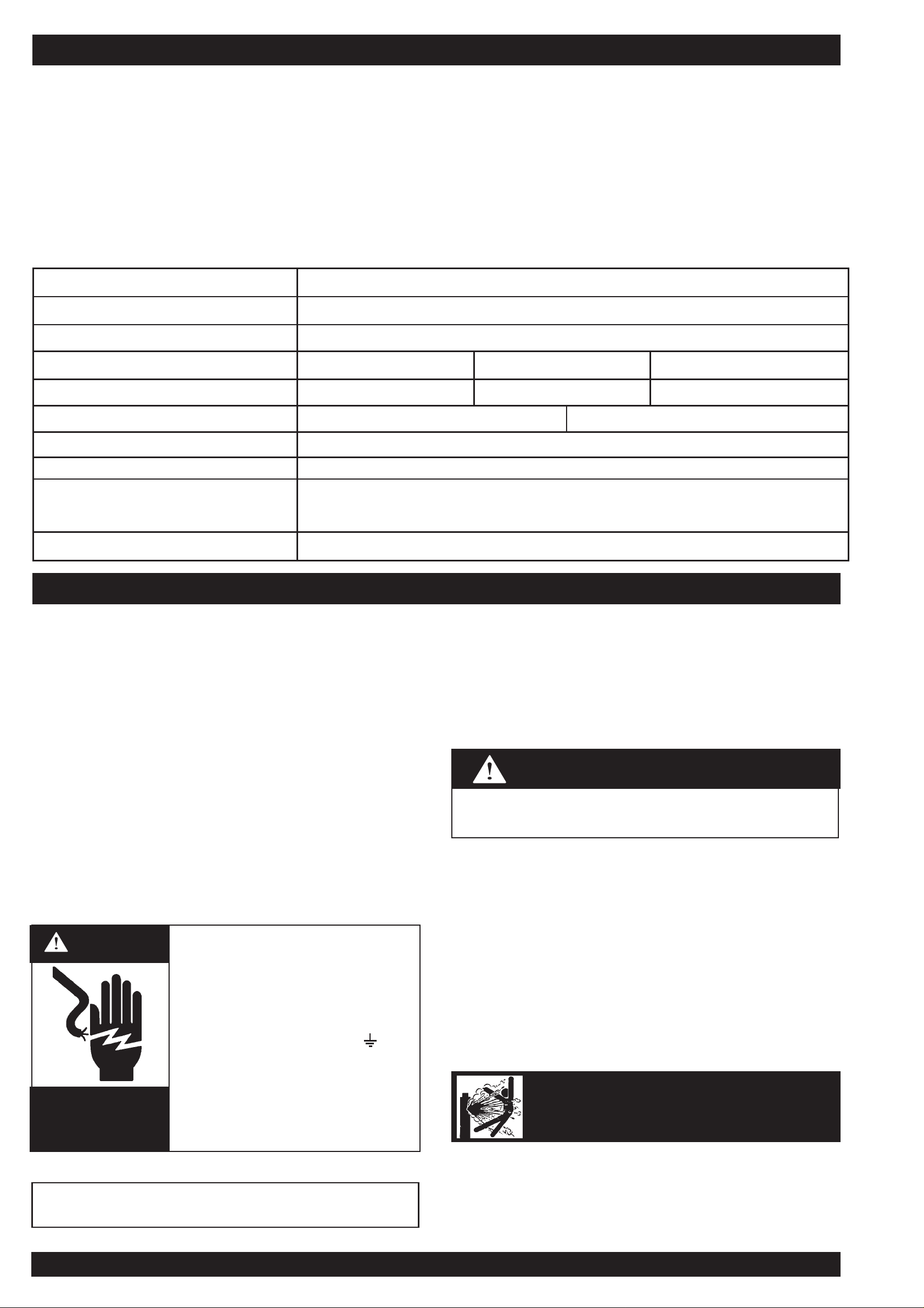
• Turn the input power off at the
disconnect switch before installing
or servicing this machine.
• Do not touch electrically “hot” parts
such as output terminals or internal
wiring.
• Connect grounding screw ( ) to a
good earth ground.
• Do not operate with covers removed.
• Turn power switch “off” before
connecting or disconnecting cables
or other equipment.
WARNING
HIGH
VOLTAGE
can kill
Page 6 CV320-I IMA 574B
PRODUCT DESCRIPTION
The CV320-I is a semi-automatic Constant Voltage DC arc welding power source and wire feeder. It combines a step controlled power
source with a separate solid state controlled wire feeder.
Excellent arc characteristics are provided for both gas shielded and self shielded welding within its current range.
For instructions on operation of the wire feeder refer to the separate instruction manual included. Standard features include output volt &
amp meters, a spot timer, gas purge facilities, a dual position 2 or 4 step trigger interlock, a Magnum FM400 gun, a regulator/flowmeter
and gas hose, a 10m electrode cable and wire feeder cable, a 3m ground cable assembly, a 3m long input lead and an undercarriage on
which a gas cylinder can be mounted.
Only qualified personnel should install or service this
equipment.
Location
Place the welder where clean cooling air can freely circulate in
through the intake louvers and out through the exhaust louvers.
Dirt, dust or any foreign material that can be drawn into the welder
should be kept at a minimum. Failure to observe these
precautions can result in excessive operating temperatures and
nuisance thermostat trips.
Wire Feeder Mounting
Locate the control cable at the rear of the CV320-I and plug into
the wire feeder. The control cable is already connected to the
CV320-I. Connect the supplied 1.5m electrode cable to the wire
feeder mechconnector and to the desired polarity terminal on the
front of the CV320-I.
Connection to Mains Supply
Before connecting the machine to the mains supply check that the
voltage and current capacity correspond to the machine voltage
and rated input current. Use a fuse or C/B per AS3000 or local
wiring rules.
The machine is supplied with an input lead fitted. Have a qualified
electrician fit a suitable input plug.
Once the above has been followed the machine can be plugged
into the mains outlet.
Shielding Gas Supply
(For the Gas Metal Arc Welding Process)
Refer “Safety in Welding and Cutting” - ANSI Standard Z49.1 and
WTIA Technical Note 7, available from the Welding Technology
Institute of Australia.
Obtain cylinder of appropriate type shielding gas for the process
being used.
1. Set gas cylinder on rear platform of the machine. Hook chain
in place to secure cylinder to rear of welder.
2. Remove the cylinder cap. Inspect the cylinder valve for
damaged threads, dirt and dust. For cylinders having an
external thread fitting, remove any dust and dirt from the
threads with a clean cloth.
CYLINDER may explode
if damaged
Part No. KA 1392 & KA1392-1
Maximum Open Circuit Voltage 45V
Output Current Range 20 to 400A
Duty Cycle 30% 60% 100%
Rated Output 320A/30V 240A/26V 190A/23.5V
Rated Input KA1392 415V 3ph 50Hz 13.5 amps KA1392-1 380V 3ph 50hz 14.7amps
Wire Speed Range 1-20 m/min
Weight (complete with u/c) 140 kg
H x W x L (mm) Over wire feeder,
cylinder tray & wheels
1220 x 580 x 842 mm
Operating Temperature -20˚C to 40˚C
Specifications
INSTALLATION
Never connect the green/yellow conductor to any of the
three active supply lines from the mains. This conductor is
to earth the machine as required by Electrical Regulations.
CAUTION
Page 7
IMA 574B CV320-I Page 7
DO NOT ATTACH THE REGULATOR/FLOWMETER IF
CYLINDER VALVE IS DAMAGED! Inform your gas supplier of this
condition.
3. Stand to one side away from the outlet and open the cylinder
valve for an instant. This blows away any dust or dirt which
may have accumulated in the valve outlet.
4. Inspect the regulator/flowmeter for damaged threads and
seals, dirt and dust. Remove dust and dirt with a clean cloth.
DO NOT USE THE REGULATOR/FLOWMETER IF DAMAGE
IS PRESENT! Have an authorised repair station repair any
damage.
5. Attach the regulator/flowmeter to the cylinder valve and
tighten the union nut(s) securely with a spanner.
6. Attach the inlet gas hose to the outlet fitting of the
regulator/flowmeter, and tighten the union nut securely with a
spanner.
7. Before opening the cylinder valve, turn the regulator adjusting
knob counter-clockwise until the adjusting spring pressure is
released.
8. Open the cylinder valve slowly a fraction of a turn. When the
cylinder pressure gauge pointer stops moving, open the valve
fully.
9. The regulator/flowmeter is adjustable. Set it for the flow rate
recommended for the procedure and process being used
before starting to weld.
Gun and Cable
The Magnum FM400 gun and cable provided with the machine is
set up for 0.9/1.2mm operation.
1. Lay the cable out straight.
2. Make sure all pins on the gun cable connector are aligned
with the proper mating sockets on the front panel gun
connector and then join the connectors and tighten the hand
nut on the gun cable connector.
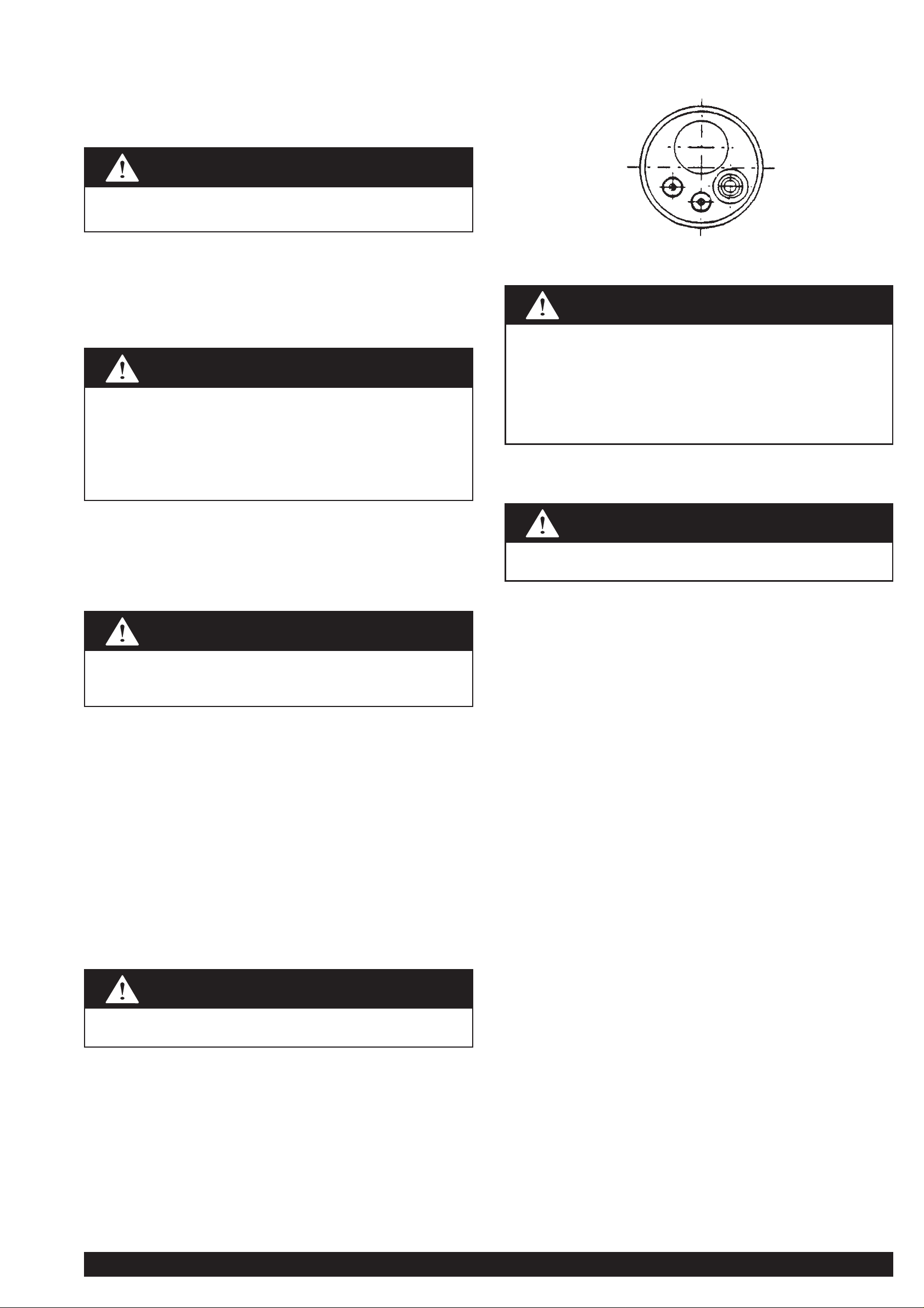
NOTE: If a gun and cable other than the Magnum FM400 gun are
to be used, they must conform to standard European-style
connector specifications. See diagram under.
The gun trigger switch must be capable of switching 10 milliamps
at 60 volts DC—resistive.
Output Polarity Connection
Connect the lead from the wire feeder to the output stud of the
desired polarity.
Connect the work lead to the other output stud.
Be sure to keep your face away from the valve outlet
when “cracking” the valve.
Gas under pressure is explosive. Always keep gas
cylinders in an upright position and always keep chained
to undercarriage or stationary support. Refer “Safety in
Welding and Cutting” - ANSI Standard Z49-1 and WTIA
Technical Note 7 available from the Welding Technology
Institute of Australia.
Turn the welder power switch off before installing gun
and cable.
The gun trigger switch connected to the gun trigger
control cable must be a normally open, momentary
switch. The terminals of the switch must be insulated
from the welding circuit. Improper operation of, or
damage to, the machine might result if this switch is
common to an electrical circuit other than the machine
trigger circuit.
Turn the welder power switch off before changing output
connection.
Never stand directly in front of or behind the
regulator/flowmeter when opening the cylinder valve.
Always stand to one side.
WARNING
WARNING
WARNING
WARNING
CAUTION
WARNING
Page 8
Page 8 CV320-I IMA 574B
IMPORTANT SAFETY NOTE: In 2T mode, this DC Constant
Voltage wire welder provides “COLD” electrode when the gun
trigger is not operated. Conversely, the output terminals are
“LIVE” when the gun trigger is “activated” when pressed in 2T
mode, or triggered on in 4T mode.
Refer to wire feeder manual for a description of the 2T/4T trigger
operation.
Duty Cycle
The machine is rated at the following duty cycles:
* Based on 10 min. time period (i.e., for 60% duty cycle, it is 6
minutes actual welding and 4 minutes with no welding output,
but with the input power remaining on keeping the cooling fans
operative.)
Control Panel
Power Switch
The mains power switch is incorporated in the “coarse” output
voltage control rotary switch. In the “0” position (fully counter
clockwise) the input mains power is switched off.
ARC RAYS
can burn
Pilot Light
This light illuminates when the input mains power is switched on
Volts Control
The output voltage is controlled by two rotary switches. One rotary
switch provides four “coarse” voltage settings as well as switching
the mains power on. The other rotary switch provides the user with
a selection of eight “fine” voltage settings. The selection between
these two rotary switches allows the user to select any one of
thirty-two welding voltages.
The approximate weld voltages for the rotary switch positions are:
Current Control
Use the wire feed speed control on the wire feeder to adjust the
speed at which the electrode wire feeds when welding. This is in
effect a current control as the power source will deliver the current
necessary to melt the wire. The higher the speed, the more current
will be required.
Over temperature light
Indicates that the thermostats have operated to protect unit from
over temperature.
Setting Up for Welding
(Also refer to the wire feeder instruction manual.)
The following items are required:
1) A reel of wire of suitable size and type .
2) A suitable gun and cable assembly with a “Euro” connector
and the correct tip and, if necessary gas nozzle for the
consumable being used. (A Magnum FM400 gun is supplied).
3) A work return cable and clamp. (supplied)
4) Normal welding accessories including helmet or hand shield
with suitable lens, gloves etc.
5) If a gas shielded process is to be used, a cylinder of
appropriate gas is required. (Regulator/flowmeter and hose
are supplied.)
Coarse Fine Volts Coarse Fine Volts
1 1 13.0 2 1 18.0
1 2 14.0 2 2 18.5
1 3 15.0 2 3 19.0
1 4 16.0 2 4 19.5
1 5 16.5 2 5 20.0
1 6 17.0 2 6 20.5
1 7 17.5 2 7 21.0
1 8 18.0 2 8 21.5
3 1 21.5 4 1 25.0
3 2 22.0 4 2 25.5
3 3 22.5 4 3 26.0
3 4 23.0 4 4 26.5
3 5 23.5 4 5 27.0
3 6 24.0 4 6 28.0
3 7 24.5 4 7 29.0
3 8 25.0 4 8 30.0
WARNING
ELECTRIC
SHOCK
can kill
FUMES AND
GASES can be
dangerous
WELDING SPARKS
can cause fire or
explosion
• Do not touch electrically live parts or
electrode with skin or wet clothing.
• Insulate yourself from work and
ground.
• Always wear dry insulating gloves.
• Keep your head out of fumes.
• Use ventilation or exhaust to remove
fumes from breathing zone.
• Keep flammable material away.
• Do not weld upon containers which
have held combustibles.
• Wear eye, ear and body protection.
Duty Cycle* Output Amps Arc V olts
30% 320 30
60% 240 26
100% 190 23.5
OPERATING INSTRUCTIONS
Page 9

IMA 574B CV320-I Page 9
If gas shielding is required, see Section 1.4. Connect the gas
hose.
Remember that gas cylinders may explode if damaged, so ensure
that all gas cylinders are securely mounted.
Ensure there are no kinks or sharp bends in the gun cable and
hold the wire inch button until the wire emerges from the gun. It is
good practice to remove the tip when first feeding a new coil of
wire, then refit over the wire and tighten.
Cut off the end of the wire leaving 10mm to 15mm stick-out.
The gun polarity is selected by connecting the wire feeder cable to
the required output stud. e.g. electrode (+) - connect the lead to
the (+) output stud. For electrode (-) - connect the lead to the (-)
output stud.
Connect the work lead to the other output stud.
Welding
Put into 2T mode.
Select the output voltage required to suit the job by setting the
coarse and fine rotary switches.
Before beginning welding, ensure the wire protrudes from the gun
tip by approximately 10-15mm. Ensure welding shield and other
protective clothing are in place. Present the protruding electrode
just off the work. Maintain a steady grip on the gun, protect your
eyes with a welding shield, then press and hold the gun trigger to
create the arc.
If it is necessary to adjust the weld voltage, stop welding before
changing either or both of the rotary switches.
Adjust the wire feed speed as necessary to suit the job. At the
completion of the weld, release the gun trigger and pull the gun
away from the work to stop the arc.
4T mode should only be used by experienced operators for long
welds.
Maintenance
Safety Precautions
Routine Maintenance
General
In extremely dusty locations, dirt may clog the air passages and
cause the welder to run hot. Blow dirt out of the welder with lowpressure air at regular intervals to eliminate excessive dirt and
dust build-up on internal parts.
The fan motor has sealed ball bearings which require no service.
Welding Thermal Overload Protection
The CV320-I has built-in protective thermostats that respond to
excessive temperature. They open the wire feed and welder
output circuits if the machine exceeds the maximum safe
operating temperature because of a frequent overload, or high
ambient temperature plus overload. The over temperature light
glows when the thermostats open. The thermostats automatically
reset when the temperature reaches a safe operating level.
Gun and Cable Maintenance
Cable Cleaning
Clean cable liner after using approximately 150kg of electrode.
Remove the cable from the wire feeder and lay it out straight on
the floor. Remove the contact tip from the gun. Using an air hose
and approx. 350 kPa (50psi) pressure, gently blow out the cable
liner from the gas diffuser end.
Flex the cable over its entire length and again blow out the cable.
Repeat this procedure until no further dirt comes out.
Gun Tips and Nozzles
The gun tip should be replaced when worn. Replace with the
correct size for the wire type and diameter. Too large a tip for the
electrode wire will cause arcing within the gun cable and possible
jamming of the wire within the cable .
Remove spatter from inside of gas nozzle and from tip after each
10 minutes of arc time or as required.
Procedure for Replacing PC Boards
When a PC Board is to be replaced, the following procedure must
be followed:
Visually inspect PC Board in question.
1. Are any of the components damaged?
2. Is a conductor on the back side of the board damaged?
3. If there is no damage to the PB Board, insert a new PC Board
and see if this remedies the problem. If the problem is
remedied, reinstall the old PC Board and see if the problem
still exists with the old PC Board.
a) If the problem does not exist with the old board, check the
PC Board lead harness plugs.
b) Check leads in the harness for loose connections.
When the gun trigger is pressed (2T mode) or pressed and
released the first time (4T mode), the wire is at welding
voltage. The wire should never touch the case of the wire
feeder. If it does, it is possible for the wire to arc to the case.
Any wire overrun should be avoided.
(Refer wire feeder instruction manual.)
WARNING
ELECTRIC
SHOCK
can kill
• Have an electrician install and
service this equipment.
• Turn the input power off at the fuse
box,or unplug input lead before
working on equipment.
• Do not touch electrically hot parts.
WARNING
Excessive air pressure at the start of cable cleaning may
cause dirt to form a plug.
WARNING
Turn the welder power switch off before removing gun tips
and nozzles.
WARNING
Page 10

Page 10 CV320-I IMA 574B
WARNING
ELECTRIC
SHOCK
can kill
• Have an electrician install and
service this equipment.
• Turn the input power off at the fuse
box before working on equipment.
• Do not touch electrically hot parts.
Problem
Rough wire feeding or wire
not feeding but drive rolls
turning.
Variable or “hunting” arc.
Poor arc striking with
sticking or “blast offs”,
weld porosity, narrow and
ropey looking bead, or
electrode stubbing into
plate while welding.
Tip seizes in diffuser.
Possible Cause
Gun cable kinked and/or twisted.
Wire jammed in gun and cable.
Incorrectly fitted drive roll.
Drive roll loose.
Gun cable dirty.
Worn drive roll.
Electrode rusty and/or dirty.
Worn nozzle or cable liner.
Partially flashed or melted contact tip.
Incorrect idle roll pressure.
Wrong size, worn and/or melted contact tip.
Worn work cable or poor work connection.
Loose electrode connections.
Wrong polarity.
Improper procedures or techniques.
Improper gas shielding.
Tip overheating due to prolonged or
excessive high current and/or duty cycle
welding.
What To Do
Inspect gun cable and replace if necessary.
Remove wire from gun and cable - feed in new wire.
Note any obstructions in gun and cable. Replace gun
and cable if necessary.
See Wire Drive Roll Section in this manual for proper
installation of drive roll.
Remove, clean, install and tighten.
Clean cable or replace liner.
Replace.
Replace.
Replace.
Replace contact tip.
Set idle roll pressure.
Replace tip - remove any spatter on end of tip.
Inspect - repair or replace as necessary.
Be sure electrode lead is tight, gun cable tight in wire
feeder contact block, gun nozzle and gun tip tight. All
work lead connections must be tight.
Check connection at output studs for polarity required
by welding process.
See “Gas Metal Arc Welding Guide”(GS100).
Clean gas nozzle. Make certain that gas diffuser is
not restricted. Make certain that gas cylinder is not
empty or turned off. Make certain gas solenoid valve
is operating and gas flow rate is correct.
Remove gun liner and check rubber seal for any sign
of deterioration or damage. Be sure set screw in
brass connector is in place and tightened against the
liner bushing.
Do not exceed current and duty cycle rating of gun.
A light application of high temperature antiseize
lubricant may be applied to tip threads.
TROUBLESHOOTING GUIDE
Page 11

IMA 574B CV320-I Page 11
Possible Cause
Defective wire feed motor or wire drive
control PC board.
Defective wire drive control PC board.
Over-temperature protection circuit
actuated due to overload or short. Overtemperature light should be illuminated.
Faulty gun trigger switch or damaged
control cable connected to gun trigger.
Defective control PC board.
Defective contactor.
Improper settings for wire feed speed and
volts.
Faulty rotary switch either coarse control
(on/off) or fine control.
Faulty pilot transformer.
Faulty main transformer.
Faulty rectifier.
Faulty choke.
What To Do
Measure the voltage between Red motor lead
(54) and the Green motor lead (53) when the
wire inch push button is depressed. If this
voltage is over 10V DC, replace the wire feed
motor. If no voltage is registered, replace the
wire drive PCB. (Refer PCB replacement
procedure at end of Trouble Shooting Guide).
Replace PCB. (Refer PCB replacement
procedure at end of Trouble Shooting Guide).
Allow machine to cool down and reduce on
time and/or wire feed speed.
Repair.
Refer Procedure for Replacing PC Boards at
end of Trouble Shooting Guide, if no fault is
detected in trigger-thermostat circuit.
Replace defective contactor.
Set controls correctly.
Replace rotary switch.
Replace.
Replace.
Replace.
Replace.
Problem
No wire feed, although arc
voltage is present.
No control of wire feed.
No wire feed and no arc voltage.
Pilot light indicates input power to
machine.
Poor welding characteristics
and/or cannot obtain full rated
output as per nameplate.
Also see the LN21 wire feeder instruction manual
Note: This procedure is for ‘machines as built’ many modifications
could have taken place over the life of a particular machine, so
details of this procedure may need to be ‘adjusted’ to suit these
modifications.
For prompt service contact your local Lincoln Field Service Shop.
The insulation resistance values listed below are from Australian
Standard AS1966.1.
1) Disconnect input cable from power outlet.
2) Disconnect all output cables (control & weld).
3) Remove the roof panel.
4) Jumper the three (3) AC terminals and the (+) & (-) terminals
of the thre phase bridge rectifier (A total of five (5) places).
5) Jumper the four (4) meter terminals together.
6) Switch the fine control rotary switch to position one (1) &
switch the coarse control rotary switch to position
one (1).
7)
Primary test: Connect one lead of the mega tester to the
frame of the machine and the other lead to each of the three
(3) input conductors and to the main transformer primary
leads L1A, L2A & L3A. Apply the test(s).
8)
Welding circuit test: Connect one lead of the mega tester to
the frame of the machine and the other lead to the positive
output stud. Apply the test. (Min resistance 1MΩ).
9)
Welding circuit to primary test: Connect one lead of the
mega tester to the positive output stud and the other lead to
each of the three (3) input conductors and to the main
transformer primary leads L1A, L2A & L3A. Apply the test.
(Min resistance 10MΩ).
10)
Transformer thermostat test: Connect one lead of the mega
tester to the frame of the machine and the other lead to the
positive output stud. Apply the test.(Min resistance 1MΩ).
11) Remove all jumper leads.
12) Refit the roof panel.
ELECTRIC SHOCK
can kill
GROUND TEST PROCEDURE FOR CV320-I
WARNING
If any problems are encountered, refer to your nearest Lincoln Field Service Shop.
TROUBLESHOOTING GUIDE (cont)
This procedure is only suitable for applications using DC
mega testers up to 500V.
Page 12

Page 12 CV320-I IMA 574B
Machine Machine
Code 1508 Code 1413
Wire Size Part No. Part No.
Solid Wire
0.6 - 0.8mm AS4449-9 AM3023C
0.8 - 1.0mm AS4449-1 AM3023D
1.0 - 1.2mm AS4449-2 AM3023E
0.9 - 1.2mm AS4449-8
Cored Wire
0.8 - 1.0mm AS4449-3 -
1.2 - 1.6mm AS4449-4 AM3023J
Aluminium Wire
0.8 - 1.0mm AS4449-5 -
1.0 - 1.2mm - AM3023F
1.2 - 1.6mm AS4449-6 AM3023K
DRIVE ROLLS
Note: LN-21 Code Nos less than Code No. 1508 use drive roll part No.
starting with ‘AM’.
For LN-21 Code Nos greater than or equal to Code No. 1508 use drive
roll part Nos starting with ‘AS’.
Page 13

IMA 574B CV320-I Page 13
The Lincoln Electric Company (Australia) Propriety Limited
A.C.N. 000 040 308
AP-80
Operative: 2/7/99
Supercedes: 18/6/97
CV320-I
PARTS LIST AP-80
Sub Assembly
Item No. 1 2 3
Sub Assembly
Page Name
Machine Part List No. AP-80-C AP-80-D
Description Code No.
CV320-I 415V 1447 KA1392 1 1 AL2513 IMA574A
380V 1473 KA1392-1 2 1 AL2513 IMA574A
415V 1509 KA1392 1 1 AL2513 IMA574B
380V 1510 KA1392-1 2 1 AL2513 IMA574B
415V 1535 KA1392 1 1 AL2513 IMA574B
LN-21 1413 KA1389 AP-68 N/A AM3392 IMA565A
1508 KA1389 AP-68 N/A AM3392 IMA565B
Do not use this Parts List for a machine if its code number is not listed. Contact the Service Department for any code numbers not listed.
Numbers in the table below indicate which column to use in each parts list for each individual code number.
General Assembly
Control Panel Assembly
Wiring Diagram
Specification No.
Instruction Manual
Page 14

Page 14 CV320-I IMA 574B
General Assembly AP-80-C
Roof and side panels
not shown for clarity.
Platform shown this
view only.
Front panel not shown for clarity.
Ref: AG1369
A15-5-96M
AP-80-C
Operative: 2/7/99
Supercedes: 18/6/97
Page 15

IMA 574B CV320-I Page 15
General Assembly AP-80-C.1
When ordering parts quote AP-80-C-1, Machine Serial & Code Numbers, Part Description and Item Number.
Item Part No. Description Qty. 1 2
34 M6819-4A Fan 1 X X
Loctite #262 1.0mL X X
35 M7468-2 Fan Motor 1 X X
36 M15562F Fan Motor Bracket 1 X X
Items Not shown
36 AT2980-2 Cable Tie 9 X X
37 T12068-1 Insulating Splice 6 X X
38 AS4453-2 Resistor/Diode & Lead Assembly 1 X X
39 Multi-Lead /41/41B 1 X X
40 Lead /4 1 X X
41 Lead Earth 1 X X
42 Lead /44 1 X X
43 Lead /43A 1 X X
44 Lead /L1B 1 X X
45 Lead /L1A 1 X X
46 Lead /L2A 1 X X
47 Lead /L3A 1 X X
48 Lead /L1 1 X X
49 Lead /L2 1 X X
50 Lead /L3 1 X X
51 Lead L3B 1 X X
52 Sleeving-Aux. Tran. Leads to Fan 1 X X
53 Sleeving-Aux. Tran. to Front Panel 1 X X
54 Sleeving-Aux. Tran./Fan to Contactor 1 X X
55 Sleeving-Contactor to Rotary.SW.1 1 X X
56 AP80 Wiring Diagram 1 X X
57 AS4244 Warning Decal 1 X X
58 AT3378 Warning Decal 1 X X
59 Input Decal Typed 1 X X
60 AS3234 Warning Tag - Input Connection 1 X X
AT2980-2 Cable Tie 1 X X
61 AL1369-115 Literature Envelope 1 X X
62 K476-9 Magnum FM400 12ft Mig Gun 1 X X
63 801E30LKAR21 Argon Regulator Flowmeter 30L/min 1 X X
64 AS4092-5 Ground cable assembly 1 X X
65 AS4050-1 Gas Hose assembly 1 X X
66 AT3873 Chain 1 X X
67 AT4069 Liftbale Washer 1 X X
[NC]
1
⁄2˝ UNC. x 1⁄2˝ Hex. Hd. Screw 1 X X
1
⁄2˝ UNC. Hex. Nut. 1 X X
1
⁄2˝ UNC. Springwasher 1 X X
5
⁄16˝ UNC. x 3⁄4˝ Hex. Hd. Screw 4 X X
5
⁄16˝ UNC. Hex. Nut 4 X X
5
⁄16˝ dia. Flatwasher 4 X X
5
⁄16˝ dia. Springwasher 4 X X
68 Plastic Bag 9˝ x 12˝ 1 X X
69 Staple 3 X X
70 KA1389 LN21 1 X X
71 Plastic Bag 1 X X
72 Pallet 1 X X
Item Part No. Description Qty. 1 2
1 AT3070-3 Connector Block 1 X X
2 AM3423 Contactor SC35 1 X X
3 AL2494-1 Main Transformer Assembly 415V 1 X
AL2494-2 Main Transformer Assembly 380V 1 X
4 Sleeving 2 X X
6 AM3388-1 Rotary Switch 8 Pos. 1 X X
7 AM3388-2 Rotary Switch 5 Pos. 1 X X
8 Cotton Tape 25.4mm wide 3.0m X X
9 AM3275-1 Choke Assembly 1 X X
10 T7028-226 Insulation Tube 2 X X
AT2882 Insulation Washer 6 X X
11 AL2480 Rectifier 1 X X
13 AL2527 Liftbale Welded Assembly 1 X X
14 S12934 Cover Seal 1 X X
15 AS4525-2 Resistor & Tag Strip Assembly 1 X X
AT3425-5 Blind Rivet
5
⁄52˝ dia. x 5⁄16˝1XX
16 G2017R Case Side Right 1 X X
17 AS4070 4˝ dia. Swivel Castor 2 X X
18 AS4071-1 8˝ Wheel 2 X X
AT2876 Push Nut 2 X X
19 AS4303 Input Lead 1 X X
T9639-1 Box Connector 1 X X
20 AT2980-2 Cable Tie 3 X X
21 AL2530 Case Rear Assembly 1 X X
22 AS4407-3 Amphenol & Lead Assembly 3m 1 X X
T9639-2 Box Connector 1 X X
AL2651-1 Cable Assy 10m (Code 1535 only) 1 X X
23 AG1358 Gas Bottle & Wire Feeder Support 1 X X
24 AG1365 Base Welded Assembly 1 X X
26 PT0051 Auxiliary Transformer 415V 1 X
PT0053 Auxiliary Transformer 380V 1 X
27 AM3040B108 Cable - Rect. (-) to Choke 1 X X
28 AM3040B107 Cable - Rect. (+) to Shunt 1 X X
29 L7699R Roof 1 X X
30 AL2524 Front panel Assembly 1 X X
32 G2018R Case Side-Left 1 X X
33 G2017R Case Side Right 1 X X
AP-80-C.1
Operative: 2/7/99
Supercedes: 18/6/97
NOTE: All screws and bolts listed in FSS release 288
Page 16

Page 16 CV320-I IMA 574B
Control Panel AP-80-D
Item Part No. Description Qty. 1
1 AG1355 Front Panel 1 X
2 AL2516 Nameplate 1 X
3 T14659-1 Fastener Button (Black) 4 X
4 AM3397-1 Voltmeter 1 X
5 AM3398-1 Ammeter 1 X
8 AM2464-1 Moulded Output Stud 2 X
9 T3960 Flange Nut 2 X
10 AS1733-3Z Self Tapping Screw 4 X
11 AS4460 Indicator Light 1 X
12 T13486-1 Pilot Light 1 X
13 S6602-22 Shunt 1 X
15 Lead / 48 1 X
16 AM3400 Meter Lead Harness 1 X
A1 AM3388-2 Output Control Switch (Coarse) 1 X
A2 AM3388-1 Output Control Switch (Fine) 1 X
1
2
3
4 5
When ordering parts quote AP-80-D, Machine serial & Code numbers, part description and item number.
AP-80-D
Operative: 2/7/99
Supercedes: 18/6/97
Ref: AL2524
(AL21-2-96M)
Page 17

IMA 574B CV320-I Page 17
This diagram is typical of the machine’s wiring. For specific detail refer to the diagram attached to the
machine itself. If the diagram has been destroyed or defaced, contact the factory quoting the machine
serial number and code number from the nameplate.
WIRING DIAGRAM CV320-I
AL2513
A5-5-99M
Page 18

Page 18 CV320-I IMA 574B
LN21 WIRE FEEDER
PARTS LIST AP-68
AP-68
Operative: 18/6/97
Supersedes: 26/11/96
Do not use this Parts List for a machine if its code number is not listed. Contact the Service Department for any code numbers not
listed.
Numbers in the table below indicate which column to use in each parts list for each individual code number.
Sub Assembly
Item No. 1 2 3
Sub Assembly
Page Name
Machine Part List No. AP-68-C
Description AP-68-C-1
Code No.
LN-21 1413 KA1389 1 AM3392 IMA565A
LN-21 1508 KA1389 2 AM3392 IMA565B
General Assembly
Wiring Diagram
Specification No.
Instruction Manual
Page 19

IMA 574B CV320-I Page 19
NOTE: All screws and bolts listed in FSS release 288
Item Part Name and Description No. Req. Part Number 1 2
1 BASE, FRONT AND REAR PANEL 1 AG1344 x -
BASE, FRONT AND REAR PANEL 1 AM3161 - x
2 PLASTIC FOOT 4 AT4084-1 x x
4 BULKHEAD 1 AM3379 x x
5 SELF TAPPING SCREW 8 AS1733-3Z x x
6 GROMMET 1 AS3086-9 x x
7 NUTSERT 4 AT3937 x x
8 SEMS SCREW 4 T10082-27 x x
9 PCB ASSEMBLY 1 AS4212-4 x x
10 NAMEPLATE MAXIDRIVE 2 1 AM3382-1 - x
NAMEPLATE MAXIDRIVE 4 1 AM3382-2 - -
NAMEPLATE LN21 1 AM3382-3 x -
11 FASTENER BUTTON 2 TI4659-1 - x
11A FASTENER BUTTON 1 T14659 x -
12 GUN ADAPTOR 1 AS4456 x x
13 HEX HD. SCREW 3 x -
SPRINGWASHER 3 x -
FLATWASHER 3 x -
HEX NUT 3 x -
13A THREAD FORMING SCREW 3 S9225-17 - x
14 RED MICROSWITCH 2 AT3561-1 x x
15 HARNESS (not shown) 1 AL2495 x x
16 CASE AND DOOR ASSEMBLY 1 AM3378U - x
CASE AND DOOR ASSEMBLY 1 AM3378R x -
17 BUFFER GROMMET 1 AS4404-2 x x
18 PLUG BOTTOM (BLACK) 1 AS4450 x x
19 TOGGLE SWITCH 1 T13562 x x
20 KNOB 2 T10491D x x
21 INSULATION 2 T12792-1 x x
22 WIRING DIAGRAM (inside panel) 1 SEE AP-68-A
General Assembly AP-68-C
AP-68-C
Operative: 18/6/97
Supercedes: 26/11/96
Ref: AG1346A
(16.7.97)
Page 20

Page 20 CV320-I IMA 574B
Item Part Name and Description No. Part Number 1 2
Req’d
25 WIRE PANEL INSULATION 1 AS4436 x x
27 DRIVE PLATE 1 AM3391-1 x -
DRIVE PLATE 1 AM3391 - -
DRIVE PLATE 1 AM3391-8 - x
28 WIRE DRIVE MOTOR AND GEARBOX 1 AM3185 x x
29 CHEESE HEAD SCREW 3 AM3054-181 x x
30 DRIVE PLATE INSULATION 1 AS4435-1 x -
DRIVE PLATE INSULATION 1 AS4435 - -
30A DRIVE PLATE INSULATION WASHER 2 AT2882 - x
32 LEAD 1 AM3040A907 x x
33 BOX CONNECTOR 1 T9639-1 x x
34 SOLENOID 1 AM3399-1 x x
36 GAS SOLENOID NIPPLE 1 AS4457 x x
36A STRAIGHT BARB TAIL 1 AT3730-11 - x
37 SELF T APPING SCREW 4 S8025-73 x x
38 SPINDLE AND READI-REEL ADAPTOR 1 K377 x -
SPINDLE & SMALL MOUNTING STAND 1 KA1395 - x
41 DISHED WASHER 1 AT2943Z x x
42 WIRE REEL DUST STRIP 1 AS4451 x x
43 DUST STRIP RETAINING PLATE 1 AS4452 x x
45 SELF T APPING SCREW 2 AS1733-3Z x x
46 WARNING DECAL 1 AS4244 x x
47 CODE AND SERIALNo. DECAL 1 x x
49 SPACERS 2 AS4463 x 50 SLEEVING (over motor leads) 1 AM3058-412 x x
51 INSULATED SPLICE (motor conn) 2 T12068-1 x x
52 DUST STRIP SUPPORT BKT. ASSY. 1 AM3402 x x
53 INSULATING BUSHES 2 AM3391-1S x x
54 DRIVE ROLL CAP SCREW 1 AM3391-1R x x
55 DRIVE ROLL 0.9 - 1.2mm SOLID 1 AS4449-8 - x
DRIVE ROLL 1.0 - 1.2mm SOLID 1 AM3023E x 56 DRIVE ROLLADAPTER 1 AM3391-3H - x
57 DRIVE PLATE MOUNTING BRACKET 1 AM3390-2 - x
58 CABLE END PLUG 1 S12020-9 x x
58 MACHINE END CONNECTOR 1 S12021-1 x x
General Assembly AP-68-C.1
AP-68-C.1
Operative: 18/6/97
Supercedes: 26/11/96
Ref: AG1346B (25.6.97)
Note: To upgrade from
the AM3391-1 drive
plate to AM3391-7 drive
plate you will also need
to purchase AM3390-2
plus S9225-7.
Note: 4 Wheel Shown.
See Fig.1 or Fig.2 for
two wheel drive.
NOTE
: All screws and bolts listed in FSS release 288
Page 21

IMA 574B CV320-I Page 21
This diagram is typical of the machine’s wiring. For specific detail refer to the diagram attached to the
machine itself. If the diagram has been destroyed or defaced, contact the factory quoting the machine serial
number and code number from the nameplate.
WIRING DIAGRAM LN21
AM 3392
(A22.1.97M)
Page 22

Page 22 CV320-I IMA 574B
Magnum Fastmate Guns
AP-202-G
AP-202-G
Operative: 10/3/97
Supercedes: New
Part No. K479-7
Magnum FM400
3.65m long
Item Part No. Description
1 Gas nozzle, Fixed, Tip recessed:
M16080-1 Magnum 400FM (9.5 mm ID)
M16080-2 Magnum 400FM (12.7 mm ID)
M16080-3 Magnum 400FM (15.9 mm ID)
M16080-4 Magnum 400FM (19.1 mm ID)
1A Gas nozzle, Fixed, Tip flush:
M16081-1 Magnum 400FM (9.5 mm ID)
M16081-2 Magnum 400FM (12.7 mm ID)
M16081-3 Magnum 400FM (15.9 mm ID)
M16081-4 Magnum 400FM (19.1 mm ID)
2 Gas nozzle, Adjustable slip-on
(requires Item 2A):
M16093-1 Magnum 200FM (15.9 mm ID)
M16082-1 Magnum 400FM (15.9 mm ID)
M16093-2 Magnum 200FM (12.7 mm ID)
M16082-2 Magnum 400FM (12.7 mm ID)
2 Gas nozzle, Recessed slip-on
(requires Item 2A):
M16082-3 Magnum 400FM (15.9 mm ID)
M16082-4 Magnum 400FM (12.7 mm ID)
Item Part No. Description
2A Nozzle insulator assembly:
S19417-1 Magnum 200FM
S19394-1 Magnum 400FM
3 Gas nozzle, Coarse thread, Tip recessed
4mm (requires Item 3A):
M16830-1 Magnum 400FM (15.9 mm ID)
M16830-2 Magnum 400FM (19.1 mm ID)
3 Gas nozzle, Coarse thread, Tip recessed
12.7mm (requires Item 3A):
M16830-3 Magnum 400FM (15.9 mm ID)
M16830-4 Magnum 400FM (19.1 mm ID)
3A M16937-1 Nozzle Insulator Ass., Magnum 400FM
4 Contact tip, Tapered:
S19393-5 Magnum 200FM (0.6mm)
S19393-6 Magnum 200FM (0.8mm)
S19393-1 Magnum 200FM, 400FM (0.9mm)
S19393-7 Magnum 200FM, 400FM (1.0mm)
S19393-2 Magnum 200FM, 400FM (1.2mm)
S19393-3 Magnum 400FM (1.3mm)
S19393-4 Magnum 400FM (1.6mm)
Page 23

IMA 574B CV320-I Page 23
Item Part No. Description
5 Contact tip, Heavy duty:
S19392-1 Magnum 200FM, 400FM (0.9mm)
S19392-6 Magnum 200FM, 400FM (1.0mm)
S19392-2 Magnum 200FM, 400FM (1.2mm)
S19392-3 Magnum 400FM (1.3mm)
S19392-4 Magnum 400FM (1.6mm)
S19392-5 Magnum 400FM (2.0mm)
6 Contact tip, Standard duty:
S19391-6 Magnum 200FM (0.6mm)
S19391-7 Magnum 200FM (0.8mm)
S19391-1 Magnum 200FM, 400FM (0.9mm)
S19391-8 Magnum 200FM, 400FM (1.0mm)
S19391-2 Magnum 200FM, 400FM (1.2mm)
S19391-3 Magnum 400FM (1.3mm)
S19391-4 Magnum 400FM (1.6mm)
S19391-5 Magnum 400FM (2.0mm)
6A Contact tip, Notched, for Aluminium:
S18697-44 Magnum 200FM (0.8mm)
S18697-45 Magnum 200FM (0.9mm)
S18697-46 Magnum 200FM (1.2mm)
7 Gas Diffuser assembly:
S19418-2 Magnum 200FM (0.6-0.8mm)
S19418-1 Magnum 200FM (0.9-1.2mm)
S19395-1 Magnum 400M (0.6-2.0mm)
8 Cable Liner (trim to fit):
M16087-2 Magnum 200FM (0.6-0.8mm)
M16087-1 Magnum 200FM (0.9-1.2mm)
M16083-1 Magnum 400FM (0.9-1.2mm)
M16083-2 Magnum 400FM (1.3-1.6mm)
M16083-3 Magnum 400FM (1.6-2.0mm)
8 Cable Liner for Aluminium (trim to fit):
M16107-1 Magnum 200FM (0.9-1.2mm)
9 Gun tube, 60˚:
M15659-1 Magnum 200FM§, 400FM (400amp)
M15659-2 Magnum 200FM§, 400FM (300amp)
S19440 Magnum 200FM (200amp)
10 Gun tube, 45˚:
M15685-1 Magnum 200FM§, 400FM (400amp)
M15685-2 Magnum 200FM§, 400FM (300amp)
10 Gun Tube Insulator
T10642-172 Magnum 200FM, 400FM
11 M15693 Hanger
12 S18831 Collar assembly
13 S9776-7 Retaining ring
14 S15921-2 Clamp for gun tube
15 G1927 Gun housing, left, Magnum 400FM
G1928 Gun housing, right, Magnum 400FM
G2090 Gun housing, left, Magnum 200FM
G2091 Gun housing, right, Magnum 200FM
16 S18825-1 #6 x 32 screw
17 T14438 Clamping screw
18 S18932 Trigger assembly
19 T13483-8 ‘O’ ring
20 S18655-1 Connector assembly, Magnum 400FM
Connector assembly includes:
Retaining ring (S9776-7)
Clamping screw (T14438)
Clamp for gun tube (S15921-2)
‘O’ ring (T13483-8)
21 S19067 Connector nut (gun tube) Magnum 200FM
S18749-2 Connector nut (gun tube) Magnum 400FM
22 S19492-2 Terminals (trigger switch)
23 L7761-11 Cable assembly, 3m (10ft)
Magnum 200FM
ItemPart No. Description
23 L7761-16 Cable assembly 3.6m (12ft)
Magnum 400FM
24 S18787 Strain relief, Magnum 400FM
S18787-1 Strain relief, Magnum 200FM
25 S18786 Strain relief housing, Magnum 400FM
S18786-1 Strain relief housing, Magnum 200FM
26 M15751 Handle boot, Magnum 400FM
M15751-1 Handle boot, Magnum 200FM
27 S18930 Boot nut (moulded)
28 S18895-1 Cable boot, Magnum 200FM
S18895-2 Cable boot, Magnum 400FM
29 T11141-8 Cable clamp, Magnum 400FM
T11141-9 Cable clamp, Magnum 200FM
30 M15808 Cable handle (moulded)
31 S19067 Incoming connector nut, Magnum 200FM
S19126-2 Incoming connector nut, Magnum 400FM
32 S19153-1 Incoming connector assembly
Magnum 200FM
32 S19153 Incoming connector assembly
Magnum 400FM
33 S19008-1 Terminal lead assembly (feeder end)
(2 required).
34 S18929 Collar nut (moulded)
35 S18948-2 Central adaptor assembly
36 S18991 Liner nut
37 T1473-19 Screw
Magnum Gun
Replacement Parts AP-202-G.1
When ordering parts quote machine code and serial numbers, parts list number, item and part number and description.
AP-202-G.1
Operative: 10/3/97
Supercedes: New
§ 300 & 400 amp gun tubes can be used with 200 amp guns. Use corresponding amperes gas diffuser, nozzle and nozzle insulator.
Page 24

Page 24 CV320-I IMA 574B
Industry Lincoln ID
Ref No. Part No. Qty mm (Inches)
21T-37 M16294 1 9.5 (0.38)
21T-50 M16684-1 1 12.7 (0.50)
21T-62 M16684-1 1 15.9 (0.62)
M16080-1 1
23-37 M16080-1D 5 9.5 (0.38)
M16080-1M 25
M16080-2 1
23-50 M16080-2D 5 12.7 (0.50)
M16080-2M 25
M16080-3 1
23-62 M16080-3D 5 15.9 (0.62)
M16080-3M 25
M16080-4 1
23-75 M16080-4D 5 19.1 (0.75)
M16080-4M 25
23H-62 M17256-1 1 15.9 (0.62)
M17256-1M 25
Industry Lincoln ID
Ref No. Part No. Qty mm (Inches)
21-50-F M16294 1 12.7 (0.50)
M16081-1 1
23-37F M16081-1D 5 9.5 (0.38)
M16081-1M 25
M16081-2 1
23-50F M16081-2D 5 12.7 (0.50)
M16081-2M 25
M16081-3 1
23-62F M16081-3D 5 15.9 (0.62)
M16081-3M 25
M16081-4 1
23-75F M16081-4D 5 19.1 (0.75)
M16081-4M 25
Industry Lincoln ID
Ref No. Part No. Qty mm (Inches)
M16093-2 1
22-50 M16093-2D 5 12.7 (0.50)
M16093-2M 25
M16093-1 1
22-62 M16093-1D 5 15.9 (0.62)
M16093-1M 25
M16082-2 1
24A-50 M16082-2D 5 12.7 (0.50)
M16082-2M 25
M16093-1 1
24A-62 M16093-1D 5 15.9 (0.62)
M16093-1M 25
Industry Lincoln ID
Ref No. Part No. Qty mm (Inches)
M16082-4 1
24A-50-SS M16082-4D 5 12.7 (0.50)
M16082-4M 25
M16082-3 1
24A-62-SS M16082-3D 5 15.9 (0.62)
M16082-3M 25
Industry Lincoln ID
Ref No. Part No. Qty mm (Inches)
24CT-62-R M16830-3 1 15.9 (0.62)
M16830-3M 25
24CT-62-S M16830-1 1 15.9 (0.62)
M16830-1M 25
24CT-75-R M16830-4 1 19.1 (0.75)
M16830-4M 25
24CT-75-S M16830-2 1 19.1 (0.75)
M16830-2M 25
25CT-62 M16831-1 1 15.9 (0.62)
M16831-1M 25
25CT-75 M16831-2 1 19.1 (0.75)
M16831-2M 25
26CT-62 M16832-1 1 15.9 (0.62)
M16832-1M 25
26CT-75 M16832-2 1 19.1 (0.75)
M16832-2M 25
26CT-62-R M16832-3 1 15.9 (0.62)
M16832-3M 25
26CT-75-R M16832-4 1 19.1 (0.75)
M16832-4M 25
Industry Lincoln ID
Ref No. Part No. Qty mm (Inches)
M16970-1 1
26I-62 M16970-1D 5 15.9 (0.62)
M16970-1M 25
M16970-2 1
26I-75 M16970-2D 5 19.1 (0.75)
M16970-2M 25
M16970-3 1
26I-87 M16970-3D 5 22.1 (0.87)
M16970-3M 25
Industry Lincoln
Ref No. Part No. Qty
32 S19417-1D 5
S19417-1M 25
34A S19394-1D 5
S19394-1M 25
34CT M16937-1 1
M16937-1M 25
35CT M16937-2 1
M16937-2M 25
36CT M16937-3 1
M16937-3M 25
NOZZLE INSULATOR ASSEMBLIES
SELF-INSULATED GAS NOZZLES
FIXED GAS NOZZLES, COARSE THREAD
RECESSED SLIP-ON GAS NOZZLES
ADJUSTABLE SLIP-ON GAS NOZZLES
FIXED GAS NOZZLES, TIP FLUSH
FIXED GAS NOZZLES, TIP RECESSED
Magnum Replacement Parts
CROSS REFERENCE GUIDE FOR MAGNUM MIG CONSUMABLE PARTS
Page 25

IMA 574B CV320-I Page 25
Industry Lincoln Wire Size
Ref No. Part No. Qty mm (Inches)
11-23 S19726-1D 10
S19726-1M 25 0.6 (0.025)
11-30 S19726-2D 10
S19726-2M 25 0.8 (0.030)
11-35 S19726-3D 10
S19726-3M 25 0.9 (0.035)
11-45 S19726-4D 10
S19726-4M 25 1.2 (0.045)
14-23 S19391-6D 10
S19391-6M 25 0.6 (0.025)
14-30 S19391-7D 10
S19391-7M 25 0.8 (0.030)
14-35 S19391-1D 10
S19391-1M 25 0.9 (0.035)
14-40 S19391-8D 10
S19391-8M 25 1.0 (0.040)
14-45 S19391-2D 10
S19391-2M 25 1.2 (0.045)
14-52 S19391-3D 10
S19391-3M 25 1.3 (0.052)
14-116 S19391-4D 10
S19391-4M 25 1.6 (1/16)
14-564 S19391-6D 10
S19391-6M 25 2.0 (4/64)
Industry Lincoln Size
Ref No. Part No. Qty mm (Inches)
14H-35 S19392-1D 10
S19392-1M 25 0.9 (0.035)
14H-40 S19392-6D 10
S19392-6M 25 1.0 (0.040)
14H-45 S19392-2D 10
S19392-2M 25 1.2 (0.045)
14H-52 S19392-3D 10
S19392-3M 25 1.3 (0.052)
14H-116 S19392-4D 10
S19392-4M 25 1.6 (1/16)
14H-564 S19392-5D 10
S19392-5M 25 2.0 (5/64)
Machine Machine
Code 1508 Code 1413
Wire Size Part No. Part No.
Solid Wire
0.6, 0.8mm AS4449-9 AM3023C
0.8, 1.0mm AS4449-1 AM3023D
1.0, 1.2mm AS4449-2 AM3023E
0.9, 1.2mm AS4449-8
Cored Wire
0.8, 1.0mm AS4449-3 -
1.2, 1.6mm AS4449-4 AM3023J
Aluminium Wire
0.8, 1.0mm AS4449-5 -
1.0, 1.2mm - AM3023F
1.2, 1.6mm AS4449-6 AM3023K
Industry Lincoln Wire Size
Ref No. Part No. Qty mm (Inches)
11T-23 S20278-1D 10
S20278-1M 25 0.6 (0.025)
11T-30 S20278-2D 10
S20278-2M 25 0.8 (0.030)
11T-35 S20278-3D 10
S20278-3M 25 0.9 (0.035)
11T-45 S20278-4D 10
S20278-4M 25 1.2 (0.045)
14T-23 S19393-5D 10
S19393-5M 25 0.6 (0.025)
14T-30 S19393-6D 10
S19393-6M 25 0.8 (0.030)
14T-35 S19393-1D 10
S19393-1M 25 0.9 (0.035)
14T-40 S19393-7D 10
S19393-7M 25 1.0 (0.040)
14T-45 S19393-2D 10
S19393-2M 25 1.2 (0.045)
14T-52 S19393-3D 10
S19393-3M 25 1.3 (0.052)
14T-116 S19393-4D 10
S19393-4M 25 1.6 (1/16)
15HFC-35 S20476-1M 25 0.9 (0.035)
15HFC-45 S20476-2M 25 1.2 (0.045)
15HFC-52 S20476-3M 25 1.3 (0.052)
15HFC-116 S20476-4M 25 1.6 (1/16)
15HFC-564 S20476-5M 25 2.0 (5/64)
15AHFC-364 S20476-9M 25 1.2 (3/64A)
15AHFC-116 S20476-10M 25 1.6 (1/16A)
Industry Lincoln Size
Ref No. Part No. Qty mm (Inches)
35-50 S19728 1 0.6 - 0.9 (0.025 - .035)
52 S19418-1D 5
S19418-1M 25 0.9 - 1.2 (0.035 - .045)
52-23 S19418-2D 5
S19418-2M 25 0.6 - 0.8 (0.025 - .030)
54A S19395-1D 5
S19395-1M 25 0.6 - 2.0 (0.025 - 5/64)
55 S21098-2 1
S21098-2M 25 1.6 - 2.0 (1/16 - 5/64)
55H S21098-3 1
S21098-3M 25 2.4 - 3.2 (3/32 - 1/8)
55S-H S21098-5 1
S21098-5M 25 2.4 - 3.2 (3/32 - 1/8)
55S-HL S21098-7 1
S21098-7M 25 2.4 - 3.2 (3/32 - 1/8)
55SW S21098-1 1
S21098-1M 25 0.9 - 1.6 (0.035 - 1/16)
55S-SW S21098-4 1
S21098-4M 25 0.9 - 1.6 (0.035 - 1/16)
55S-SWL S21098-6 1
S21098-6M 25 0.9 - 1.6 (0.035 - 1/16)
56S-H S20478-2 1
S20478-2M 25 1.6 - 3.2 (1/16 - 1/8)
56S-SW S20478-1 1
S20478-1M 25 0.9 - 1.6 (0.035 - 1/16)
GAS DIFFUSERS
CONTACT TIPS TAPERED
DRIVE ROLLS
CONTACT TIPS HEAVY DUTY (300A & 400A)
CONTACT TIPS STANDARD
Magnum Replacement Parts
When ordering parts, quote machine code and serial numbers,
parts list number, item and part number and description.
Note: LN-21 Code Nos. less than Code No. 1508 use drive
roll Part Nos. starting with ‘AM’.
For LN-21 Code Nos. greater than or equal to Code No. 1508
use drive roll Part Nos. starting with ‘AS’.
Page 26

The Lincoln Electric Company (Australia) Pty Limited (“Lincoln”) warrants all new
machinery and equipment (“goods”) manufactured by Lincoln against defects in
workmanship and material subject to certain limitations hereinafter provided.
Certain conditions warranties and obligations are implied by law (for example
under the Trade Practices Act 1974) and cannot be excluded or modified (“the
statutory warranties”).
Where the statutory warranties do apply then any express warranties given by
Lincoln (the “express warranties”) are given in addition and without derogation from
the statutory warranties. Apart from the express warranties and (in cases where
they apply by law but not otherwise) the statutory warranties Lincoln gives no
warranties whether express or implied by operation of law or otherwise in respect
of any goods manufactured or supplied by Lincoln or by its authorised distributor.
Any warranty whether express or statutory and the term of any such warranty as
set out herein commences on the date Lincoln or Lincoln’s authorised
distributorship forwards the goods from the premises of Lincoln or Lincoln’s
authorised distributor to the purchaser.
In respect of any claim under the warranty herein provided a purchaser must
furnish Lincoln with written notice of any claim under the warranty within the time
period of the warranty as further specified herein.
The extent of Lincoln’s warranty whether express or statutory is limited to a liability
to repair, replace or pay to the purchaser an amount equal to:
a) The cost of replacing the goods;
b) The cost of obtaining equivalent goods; or
c) The cost of having the goods repaired, whichever remedy in its absolute
discretion Lincoln chooses.
Upon request by Lincoln the purchaser must permit Lincoln to inspect the goods
the subject of any claim under this warranty and Lincoln may at its absolute
discretion repair or replace the goods F.O.B. at its own premises or at such other
premises as Lincoln may designate provided that all freight charges to and from
Lincoln’s premises or such other premises as Lincoln may designate shall be paid
by the purchaser.
Period of Warranty
The period of warranty in respect of goods covered by this warranty shall be as
follows:
a) In respect of manual and semi-automatic and fully automatic wire feeders
and welders (except belted, engine driven welders and alternator sets) - 3
years from the date of commencement of the warranty;
b) In respect of the Invertec V130-S inverter - 1 year from the date of sale.
c) In respect of belted, engine driven welders and alternator sets designed for
operating speeds under 2,000 rpm - 3 years from the date of
commencement of the warranty;
d) In respect of Tractapac mobile rural welders mounted in approved fixtures
- 3 years from the date of commencement of the warranty;
e) In respect of belted, engine driven welders and alternator sets designed for
operating speeds over 2,000 rpm - 2 years from the date of
commencement of the warranty;
f) Other goods manufactured by Lincoln including gun and cable assemblies,
undercarriages, field installed options, unattached options, welding
supplies, standard accessory sets and replacement parts -1 year from the
date of commencement of the warranty;
g) In respect of all alternators irrespective of the manufacturer of those
alternators - 12 months in respect of labour and parts from the date of
commencement of the warranty;
h) To the extent permitted by law Lincoln shall be entitled to in its absolute
discretion repair all engines and engine accessories however Lincoln shall
not be held responsible for any such repair which shall be the sole
responsibility of the engine manufacturer which provides for warranties for
the period and subject to any limitations provided for by those
manufacturers of the respective engines and engine accessories.
At the date of this warranty the details of those manufacturers warranties are as
follows:
Engine Manufacturer Labour Parts
i) Perkins Engines and Accessories *24 months *24 months
(The Perkins Distributor Organisation *Subject to conditions
provides all warranty service (accessories imposed by Perkins
included) for the Perkins Engines powering
goods manufactured by Lincoln.)
ii) Onan, Lombardini, Kubota & 12 months 12 months
Ruggerini Engines and their
Accessories
(warranty service can only be carried out by
authorised Lincoln Field Service Shop or
the engine distributors authorised by the
Lincoln branch office)
iii) Intermotor Engines and Accessories 12 months 12 months
(warranty services can only be carried out
by an authorised Lincoln F.S.S. or other
agency approved by the Lincoln branch
office)
iv) Briggs & Stratton Vanguard Engines *24 months *24 months
and Accessories •The Magnetron ignition
(warranty service can only be carried system is warranted by
out by an authorised Briggs & Stratton Briggs & Stratton for 5 years.
service dealer).
Exclusions
Subject to the express and statutory warranties hereinbefore provided Lincoln
provides no other warranties in respect of the manufacture or sale of goods and
in particular Lincoln shall have no responsibility or liability in respect of:
a) Repairs done to Lincoln’s goods and undertaken by the purchaser outside
Lincoln’s premises without written authority from Lincoln obtained prior to any
such repair;
b) Any damage or failure of the goods as a result of normal wear and tear or the
neglect misuse abuse or failure to properly service goods by any purchaser.
The liability of Lincoln is limited as hereinbefore provided and Lincoln shall not be
liable for any incidental special or consequential damage suffered by a purchaser
whether or not arising out of circumstances known or foreseeably known by
Lincoln and in particular arising out of the supply of goods to a purchaser or the
use of goods by a purchaser whether based on breach of contract negligence or
tort.
Lincoln supplies certain batteries in connection with its supply of goods and the
purchaser acknowledges that any such battery is warranted by its manufacturer
and any claim in respect of such a battery whether as to a defect in the battery or
as to damage consequential upon a defect in a battery shall be made by the
purchaser to the manufacturer of the battery and the purchaser shall not hold
Lincoln in any way liable for the operation non-operation or malfunction of any
such battery.
WARRANTY
IN LINE WITH THE COMP ANY'S POLICYOF CONTINUING PRODUCT IMPROVEMENT, SPECIFICATIONS HEREIN ARE SUBJECTTO MODIFICATION OR CHANGE WITHOUTNOTICE
Spare Parts Policy
As a manufacturer Lincoln undertakes to support its product with supply of spare parts. Lincoln policy in the case of light to medium duty welding equipment is to provide
full parts support for the period of 10 years from last manufacture. In the case of heavy duty industrial and fully automatic equipment, Lincoln undertakes to provide full parts
support for a period of 15 years from last manufacture date of any model.
Lincoln recognises that it is totally bound by the policy of its suppliers with regard to purchase items, however, the above policy will apply to purchase items and components
and Lincoln practice is to take into its stock appropriate levels of inventory at the time it ceases to buy for current manufacturing to ensure its overall policy is followed. Where
possible, due to common usage or availability, Lincoln will continue to supply beyond the above periods, however, Lincoln will not undertake special manufacture outside
these guidelines unless a customer is willing to accept the appropriate set up charge where tooling has been retained, and the delivery as dictated by manufacturing demand.
THE LINCOLN ELECTRIC CO.
Cleveland, Ohio, U.S.A. - Subsidiary companies established in Australia, Canada, Europe, North and South America.
Version 7/99
Reprint 100
The Lincoln Electric Company
(Australia) Pty. Ltd.
A.C.N. 000 040 308
35 Bryant Street, Padstow, Sydney 2211, Australia
Telephone: (02) 9772-7222 Fax: (02) 9792-1387
International: Ph: +61 2 9772-7222 Fax: +61 2 9792-1387
In Australia, Lincoln Technical Sales Representatives are located in
Townsville, Mackay, Gladstone, Brisbane, Newcastle, Sydney, Wollongong,
Melbourne, Tasmania, Adelaide and Perth. To contact your local Lincoln
Technical Sales Representative, call 1300 728 720 (for the cost of a
local call). Lincoln products are sold primarily through its distributors. Our
Regional Office locations are:
Northern Region: 240 Evans Road, Salisbury, Qld, 4107 (07) 3277-2955
Central Region: 35 Bryant Street, Padstow, NSW, 2211 (02) 9772-7222
Southern Region: 1-3 Grange Road, Cheltenham, Vic, 3192 (03) 9584-9299
Western Region: 25 Barker Street, Belmont, WA, 6104 (08) 9277-8744
New Zealand: 152 St Georges Road, Avondale (Auckland) (9) 828-5180
Singapore: Blk 219,#02-01 Henderson Road, Singapore 276-0878
 Loading...