

Page 1
IDEALARC CV-300
SERVICE MANUAL
SVM116-A
March 1999
Safety Depends on You
Lincoln arc welding and cutting
equipment is designed and built
with safety in mind.Howev er , your
overall safety can be increased
by proper installation ... and
thoughtful operation on your part.
DO NOT INSTALL, OPERATE
OR REPAIR THIS EQUIPMENT
WITHOUT READING THIS MANUAL AND THE SAFETY PRECAUTIONS CONTAINED
THROUGHOUT. And, most
importantly, think before you act
and be careful.
For use with machines having Code Numbers:
9456,
9486,
9520,
9939,
9940,
10180,
10181.
RETURN TO MAIN INDEX
Return to Master TOC Return to Master TOC Return to Master TOC Return to Master TOC
View Safety Info View Safety Info View Safety Info View Safety Info
• Sales and Service through Subsidiaries and Distributors Worldwide •
Cleveland, Ohio 44117-1199 U.S.A. TEL: 216.481.8100 FAX: 216.486.1751 WEB SITE: www.lincolnelectric.com
World's Leader in Welding and Cutting Products Premier Manufacturer of Industrial Motors
Page 2
i
SAFETY
i
WARNING
ARC WELDING can be hazardous.
PROTECT YOURSELF AND OTHERS FROM POSSIBLE SERIOUS INJURY OR DEATH. KEEP CHILDREN
AWAY. PACEMAKER WEARERS SHOULD CONSULT WITH THEIR DOCTOR BEFORE OPERATING.
Read and understand the following safety highlights. For additional safety information, it is strongly recommended that you
purchase a copy of “Safety in Welding & Cutting - ANSI Standard Z49.1” from the American W elding Society, P.O. Box 351040,
Miami, Florida 33135 or CSA Standard W117.2-1974. A Free copy of “Arc Welding Safety” booklet E205 is available from the
Lincoln Electric Company, 22801 St. Clair Avenue, Cleveland, Ohio 44117-1199.
BE SURE THA T ALLINSTALLATION, OPERATION, MAINTENANCE AND REPAIR PROCEDURES ARE PERFORMED ONLY BY QUALIFIED INDIVIDUALS.
ELECTRIC SHOCK can kill.
1.a. The electrode and work (or ground) circuits
are electrically “hot” when the welder is on.
Do not touch these “hot” parts with your bare
skin or wet clothing. Wear dry, hole-free
gloves to insulate hands.
1.b. Insulate yourself from work and ground using dry insulation.
Make certain the insulation is large enough to cover your full
area of physical contact with work and ground.
In addition to the normal safety precautions, if welding
must be performed under electrically hazardous
conditions (in damp locations or while wearing wet
clothing; on metal structures such as floors, gratings or
scaffolds; when in cramped positions such as sitting,
kneeling or lying, if there is a high risk of unavoidable or
accidental contact with the workpiece or ground) use
the following equipment:
• Semiautomatic DC Constant Voltage (Wire) Welder.
• DC Manual (Stick) Welder.
• AC Welder with Reduced Voltage Control.
1.c. In semiautomatic or automatic wire welding, the electrode,
electrode reel, welding head, nozzle or semiautomatic
welding gun are also electrically “hot”.
1.d. Always be sure the work cable makes a good electrical
connection with the metal being welded. The connection
should be as close as possible to the area being welded.
1.e. Ground the work or metal to be welded to a good electrical
(earth) ground.
1.f.
Maintain the electrode holder, work clamp, welding cable and
welding machine in good, safe operating condition. Replace
damaged insulation.
1.g. Never dip the electrode in water for cooling.
1.h. Never simultaneously touch electrically “hot” parts of
electrode holders connected to two welders because voltage
between the two can be the total of the open circuit voltage
of both welders.
1.i. When working above floor level, use a safety belt to protect
yourself from a fall should you get a shock.
1.j. Also see Items 4.c. and 6.
2.b. Use suitable clothing made from durable flame-resistant
material to protect your skin and that of your helpers from
the arc rays.
2.c. Protect other nearby personnel with suitable, non-flammable
screening and/or warn them not to watch the arc nor expose
themselves to the arc rays or to hot spatter or metal.
fumes and gases away from the breathing zone. When
welding with electrodes which require special
ventilation such as stainless or hard facing (see
instructions on container or MSDS) or on lead or
cadmium plated steel and other metals or coatings
which produce highly toxic fumes, keep exposure as
low as possible and below Threshold Limit Values (TLV)
using local exhaust or mechanical ventilation. In
confined spaces or in some circumstances, outdoors, a
respirator may be required. Additional precautions are
also required when welding on galvanized steel.
3.b.
Do not weld in locations near chlorinated hydrocarbon
coming from degreasing, cleaning or spraying operations.
The heat and rays of the arc can react with solvent vapors
form phosgene, a highly toxic gas, and other irritating
products.
3.c. Shielding gases used for arc welding can displace air and
cause injury or death. Always use enough ventilation,
especially in confined areas, to insure breathing air is safe.
3.d. Read and understand the manufacturer’s instructions for this
equipment and the consumables to be used, including the
material safety data sheet (MSDS) and follow your
employer’s safety practices. MSDS forms are available from
your welding distributor or from the manufacturer.
ARC RAYS can burn.
2.a. Use a shield with the proper filter and cover
plates to protect your eyes from sparks and
the rays of the arc when welding or observing
open arc welding. Headshield and filter lens
should conform to ANSI Z87. I standards.
FUMES AND GASES
can be dangerous.
3.a.Welding may produce fumes and gases
hazardous to health. Avoid breathing these
fumes and gases.When welding, keep
your head out of the fume. Use enough
ventilation and/or exhaust at the arc to keep
vapors
to
Return to Master TOC Return to Master TOC Return to Master TOC Return to Master TOC
3.e. Also see item 7b.
IDEALARC CV-300
Apr. ’93
Page 3
ii
SAFETY
ii
WELDING SPARKS can
cause fire or explosion.
4.a.
Remove fire hazards from the welding area.
If this is not possible, cover them to prevent
the welding sparks from starting a fire.
materials from welding can easily go through small cracks
and openings to adjacent areas. Avoid welding near
hydraulic lines. Have a fire extinguisher readily available.
4.b. Where compressed gases are to be used at the job site,
special precautions should be used to prevent hazardous
situations. Refer to “Safety in Welding and Cutting” (ANSI
Standard Z49.1) and the operating information for the
equipment being used.
4.c. When not welding, make certain no part of the electrode
circuit is touching the work or ground. Accidental contact can
cause overheating and create a fire hazard.
4.d. Do not heat, cut or weld tanks, drums or containers until the
proper steps have been taken to insure that such procedures
will not cause flammable or toxic vapors from substances
inside. They can cause an explosion even
been “cleaned”. For information, purchase “Recommended
Safe Practices for the
Containers and Piping That Have Held Hazardous
Substances”, AWS F4.1 from the American Welding Society
(see address above).
4.e. Vent hollow castings or containers before heating, cutting or
welding. They may explode.
4.f.
Sparks and spatter are thrown from the welding arc. Wear oil
free protective garments such as leather gloves, heavy shirt,
cuffless trousers, high shoes and a cap over your hair. Wear
ear plugs when welding out of position or in confined places.
Always wear safety glasses with side shields when in a
welding area.
4.g. Connect the work cable to the work as close to the welding
area as practical. Work cables connected to the building
framework or other locations away from the welding area
increase the possibility of the welding current passing
through lifting chains, crane cables or other alternate circuits.
This can create fire hazards or overheat lifting chains or
cables until they fail.
4.h. Also see item 7c.
Remember that welding sparks and hot
though
they have
Preparation
for Welding and Cutting of
CYLINDER may explode
if damaged.
5.a. Use only compressed gas cylinders
containing the correct shielding gas for the
process used and properly operating
regulators designed for the gas and
pressure used. All hoses, fittings, etc. should be suitable for
the application and maintained in good condition.
5.b. Always keep cylinders in an upright position securely
chained to an undercarriage or fixed support.
5.c. Cylinders should be located:
•Away from areas where they may be struck or subjected to
physical damage.
• A safe distance from arc welding or cutting operations and
any other source of heat, sparks, or flame.
5.d. Never allow the electrode, electrode holder or any other
electrically “hot” parts to touch a cylinder.
5.e. Keep your head and face away from the cylinder valve outlet
when opening the cylinder valve.
5.f. Valve protection caps should always be in place and hand
tight except when the cylinder is in use or connected for
use.
5.g. Read and follow the instructions on compressed gas
cylinders, associated equipment, and CGA publication P-l,
“Precautions for Safe Handling of Compressed Gases in
Cylinders,” available from the Compressed Gas Association
1235 Jefferson Davis Highway, Arlington, VA 22202.
FOR ELECTRICALLY
powered equipment.
6.a. Turn off input power using the disconnect
switch at the fuse box before working on
the equipment.
6.b. Install equipment in accordance with the U.S. National
Electrical Code, all local codes and the manufacturer’s
recommendations.
6.c. Ground the equipment in accordance with the U.S. National
Electrical Code and the manufacturer’s recommendations.
Return to Master TOC Return to Master TOC Return to Master TOC Return to Master TOC
Feb. ’95
IDEALARC CV-300
Page 4
iii
SAFETY
iii
FOR ENGINE
powered equipment.
7.a. Turn the engine off before troubleshooting and maintenance
work unless the maintenance work requires it to be running.
____________________________________________________
7.b. Operate engines in open, well-ventilated
areas or vent the engine exhaust fumes
outdoors.
____________________________________________________
7.c. Do not add the fuel near an open flame
welding arc or when the engine is running. Stop the engine and allow it to cool
before refueling to prevent spilled fuel
from vaporizing on contact with hot
engine parts and igniting. Do not spill
fuel when filling tank. If fuel is spilled,
wipe it up and do not start engine until
fumes have been eliminated.
____________________________________________________
7.d. Keep all equipment safety guards, covers
and devices in position and in good repair.
Keep hands, hair, clothing and tools away
from V-belts, gears, fans and all other
moving parts when starting, operating or
repairing equipment.
ELECTRIC AND MAGNETIC FIELDS
may be dangerous
8.a. Electric current flowing through any conductor causes
localized Electric and Magnetic Fields (EMF). Welding
current creates EMF fields around welding cables and
welding machines
8.b. EMF fields may interfere with some pacemakers, and
welders having a pacemaker should consult their physician
before welding.
8.c. Exposure to EMF fields in welding may have other health
effects which are now not known.
8d. All welders should use the following procedures in order to
minimize exposure to EMF fields from the welding circuit:
8.d.1.
Route the electrode and work cables together - Secure
them with tape when possible.
8.d.2. Never coil the electrode lead around your body.
8.d.3. Do not place your body between the electrode and
work cables. If the electrode cable is on your right
side, the work cable should also be on your right side.
8.d.4. Connect the work cable to the workpiece as close as
possible to the area being welded.
8.d.5. Do not work next to welding power source.
____________________________________________________
7.e. In some cases it may be necessary to remove safety
guards to perform required maintenance. Remove
guards only when necessary and replace them when the
maintenance requiring their removal is complete.
Always use the greatest care when working near moving
parts.
7.f. Do not put your hands near the engine fan. Do not
attempt to override the governor or idler by pushing on
the throttle control rods while the engine is running.
7.g. To prevent accidentally starting gasoline engines while
turning the engine or welding generator during maintenance
work, disconnect the spark plug wires, distributor cap or
magneto wire as appropriate.
___________________________________________________
7.h. To avoid scalding, do not remove the
radiator pressure cap when the engine is
hot.
Mar. ’93
Return to Master TOC Return to Master TOC Return to Master TOC Return to Master TOC
IDEALARC CV-300
Page 5

iv
SAFETY
iv
PRÉCAUTIONS DE SÛRETÉ
Pour
votre propre protection lire et observer toutes les instructions
et les précautions de sûreté specifiques qui parraissent dans ce
manuel aussi bien que les précautions de sûreté générales suivantes:
Sûreté Pour Soudage A L’Arc
1. Protegez-vous contre la secousse électrique:
a. Les circuits à l’électrode et à la piéce sont sous tension
quand la machine à souder est en marche. Eviter toujours
tout contact entre les parties sous tension et la peau nue
ou les vétements mouillés. Porter des gants secs et sans
trous pour isoler les mains.
b. Faire trés attention de bien s’isoler de la masse quand on
soude dans des endroits humides, ou sur un plancher metallique ou des grilles metalliques, principalement dans
les positions assis ou couché pour lesquelles une grande
partie du corps peut être en contact avec la masse.
c. Maintenir le porte-électrode, la pince de masse, le câble de
soudage et la machine à souder en bon et sûr état defonctionnement.
d.Ne jamais plonger le porte-électrode dans l’eau pour le
refroidir.
e. Ne jamais toucher simultanément les parties sous tension
des porte-électrodes connectés à deux machines à souder parce que la tension entre les deux pinces peut être le
total de la tension à vide des deux machines.
f. Si on utilise la machine à souder comme une source de
courant pour soudage semi-automatique, ces precautions
pour le porte-électrode s’applicuent aussi au pistolet de
soudage.
zones où l’on pique le laitier.
6. Eloigner les matériaux inflammables ou les recouvrir afin de
prévenir tout risque d’incendie dû aux étincelles.
7. Quand on ne soude pas, poser la pince à une endroit isolé de
la masse. Un court-circuit accidental peut provoquer un
échauffement et un risque d’incendie.
8. S’assurer que la masse est connectée le plus prés possible de
la zone de travail qu’il est pratique de le faire. Si on place la
masse sur la charpente de la construction ou d’autres endroits
éloignés de la zone de travail, on augmente le risque de voir
passer le courant de soudage par les chaines de levage,
câbles de grue, ou autres circuits. Cela peut provoquer des
risques d’incendie ou d’echauffement des chaines et des
câbles jusqu’à ce qu’ils se rompent.
9. Assurer une ventilation suffisante dans la zone de soudage.
Ceci est particuliérement important pour le soudage de tôles
galvanisées plombées, ou cadmiées ou tout autre métal qui
produit des fumeés toxiques.
10. Ne pas souder en présence de vapeurs de chlore provenant
d’opérations de dégraissage, nettoyage ou pistolage. La
chaleur ou les rayons de l’arc peuvent réagir avec les vapeurs
du solvant pour produire du phosgéne (gas fortement toxique)
ou autres produits irritants.
11. Pour obtenir de plus amples renseignements sur la sûreté, voir
le code “Code for safety in welding and cutting” CSAStandard
W 117.2-1974.
2. Dans le cas de travail au dessus du niveau du sol, se protéger
contre les chutes dans le cas ou on recoit un choc. Ne jamais
enrouler le câble-électrode autour de n’importe quelle partie
du corps.
3. Un coup d’arc peut être plus sévère qu’un coup de soliel,
donc:
a. Utiliser un bon masque avec un verre filtrant approprié
ainsi qu’un verre blanc afin de se protéger les yeux du rayonnement de l’arc et des projections quand on soude ou
quand on regarde l’arc.
b. Porter des vêtements convenables afin de protéger la
peau de soudeur et des aides contre le rayonnement de
l‘arc.
c. Protéger l’autre personnel travaillant à proximité au
soudage à l’aide d’écrans appropriés et non-inflammables.
4. Des gouttes de laitier en fusion sont émises de l’arc de
soudage. Se protéger avec des vêtements de protection libres
de l’huile, tels que les gants en cuir, chemise épaisse, pantalons sans revers, et chaussures montantes.
5. Toujours porter des lunettes de sécurité dans la zone de
soudage. Utiliser des lunettes avec écrans lateraux dans les
Return to Master TOC Return to Master TOC Return to Master TOC Return to Master TOC
PRÉCAUTIONS DE SÛRETÉ POUR
LES MACHINES À SOUDER À
TRANSFORMATEUR ET À
REDRESSEUR
1. Relier à la terre le chassis du poste conformement au code de
l’électricité et aux recommendations du fabricant. Le dispositif
de montage ou la piece à souder doit être branché à une
bonne mise à la terre.
2. Autant que possible, I’installation et l’entretien du poste seront
effectués par un électricien qualifié.
3. Avant de faires des travaux à l’interieur de poste, la debrancher à l’interrupteur à la boite de fusibles.
4. Garder tous les couvercles et dispositifs de sûreté à leur
place.
Mar. ’93
IDEALARC CV-300
Page 6

RETURN TO MAIN INDEX
TABLE OF CONTENTS
Page
Safety . . . . . . . . . . . . . . . . . . . . . . . . . . . . . . . . . . . . . . . . . . . . . . . . . . . . . . .i - v
Installation . . . . . . . . . . . . . . . . . . . . . . . . . . . . . . . . . . . . . . . . . Section A
Technical Specifications . . . . . . . . . . . . . . . . . . . . . . . . . . . . . . . . . . . . .A-1
Safety Precautions . . . . . . . . . . . . . . . . . . . . . . . . . . . . . . . . . . . . . . . . .A-2
Select Proper Location . . . . . . . . . . . . . . . . . . . . . . . . . . . . . . . . . . . . . .A-2
Input Electrical Connections . . . . . . . . . . . . . . . . . . . . . . . . . . . . . . . . . .A-3
Reconnect Procedure . . . . . . . . . . . . . . . . . . . . . . . . . . . . . . . . . . . . . . .A-4
Connect Output Cables . . . . . . . . . . . . . . . . . . . . . . . . . . . . . . . . . . . . . .A-7
Installation of Field Installed Accessories . . . . . . . . . . . . . . . . . . . . . . . . .A-7
Installation of Wire Feeders . . . . . . . . . . . . . . . . . . . . . . . . . . . . . . . . . . .A-7
Twist-Mate Cable Plug Installation Instructions . . . . . . . . . . . . . . . . . . . .A-7
Operation . . . . . . . . . . . . . . . . . . . . . . . . . . . . . . . . . . . . . . . . . . Section B
Safety Precautions . . . . . . . . . . . . . . . . . . . . . . . . . . . . . . . . . . . . . . . . .B-1
General Description . . . . . . . . . . . . . . . . . . . . . . . . . . . . . . . . . . . . . . . .B-1
Recommended Processes and Equipment . . . . . . . . . . . . . . . . . . . . . . .B-2
Machine Capability . . . . . . . . . . . . . . . . . . . . . . . . . . . . . . . . . . . . . . . . .B-2
Limitations . . . . . . . . . . . . . . . . . . . . . . . . . . . . . . . . . . . . . . . . . . . . . . .B-2
Controls and Settings . . . . . . . . . . . . . . . . . . . . . . . . . . . . . . . . . . . . . . .B-3
Operating Steps . . . . . . . . . . . . . . . . . . . . . . . . . . . . . . . . . . . . . . . . . . .B-5
Machine and Circuit Protection . . . . . . . . . . . . . . . . . . . . . . . . . . . . . . . .B-6
vv
Accessories . . . . . . . . . . . . . . . . . . . . . . . . . . . . . . . . . . . . . . . . . . Section C
Field Installed Accessories . . . . . . . . . . . . . . . . . . . . . . . . . . . . . . . . . . .C-1
Connecting Wire Feeder to the CV-300 . . . . . . . . . . . . . . . . . . . . . . . . . .C-1
Connecting Remote Control (K857) to CV-300 . . . . . . . . . . . . . . . . . . . .C-2
Maintenance . . . . . . . . . . . . . . . . . . . . . . . . . . . . . . . . . . . . . . . . Section D
Safety Precautions . . . . . . . . . . . . . . . . . . . . . . . . . . . . . . . . . . . . . . . . .D-1
Routine and Periodic Maintenance . . . . . . . . . . . . . . . . . . . . . . . . . . . . .D-1
Theory of Operation . . . . . . . . . . . . . . . . . . . . . . . . . . . . . . . . . . . Section E
Power Supply Operation . . . . . . . . . . . . . . . . . . . . . . . . . . . . . . . . . . . .E-1
Protection Devices and Circuits . . . . . . . . . . . . . . . . . . . . . . . . . . . . . . . E-3
SCR Operation . . . . . . . . . . . . . . . . . . . . . . . . . . . . . . . . . . . . . . . . . . . .E-4
Troubleshooting and Repair . . . . . . . . . . . . . . . . . . . . . . . . . . . . Section F
How to use Troubleshooting Guide . . . . . . . . . . . . . . . . . . . . . . . . . . . . .F-1
PC Board Troubleshooting Procedures . . . . . . . . . . . . . . . . . . . . . . . . . .F-2
Troubleshooting Guide . . . . . . . . . . . . . . . . . . . . . . . . . . . . . . . . . . . . . .F-3
Diagnostic Routines and Error Codes . . . . . . . . . . . . . . . . . . . . . . . . . .F-10
Test Procedures . . . . . . . . . . . . . . . . . . . . . . . . . . . . . . . . . . . . . . . . . .F-11
Oscilloscope Waveforms . . . . . . . . . . . . . . . . . . . . . . . . . . . . . . . . . . . .F-22
Replacement Procedures . . . . . . . . . . . . . . . . . . . . . . . . . . . . . . . . . . .F-28
Electrical Diagrams . . . . . . . . . . . . . . . . . . . . . . . . . . . . . . . . . . . .Section G
Parts List . . . . . . . . . . . . . . . . . . . . . . . . . . . . . . . . . . . . . . . . . . . . . . . P-271
IDEALARC CV-300
Page 7

INSTALLATION
TABLE OF CONTENTS
- INSTALLATION SECTION -
INSTALLATION SECTION ........................................ Section A
Technical Specifications ...................................................A-1
Safety Precautions...........................................................A-2
Select Proper Location.....................................................A-2
Stacking.......................................................................A-2
Tilting...........................................................................A-2
Input Electrical Connections.............................................A-3
Fuse and Wire Sizes...................................................A-3
Reconnect Procedure.......................................................A-4
Connect Output Cables....................................................A-7
Paralleling ....................................................................A-7
Installation of Field Installed Accessories........................A-7
Installation of Wire Feeders .............................................A-7
Twist-Mate Cable Plug Installation Instructions...............A-7
Return to Master TOC Return to Master TOC Return to Master TOC Return to Master TOC
IDEALARC CV-300
Page 8
A-1
INSTALLATION
TECHNICAL SPECIFICATIONS - IDEALARC CV-300
INPUT - THREE PHASE/ 50-60 HERTZ ONLY
Standard Voltages Input Current at Rated Output
208/230/460/3/60 66/60/30 Amps
230/460/575/3/60 60/30/24 Amps
RATED OUTPUT
Duty Cycle Amps Volts at Rated Amps
CV-300 100% 300A 32
60% 400A 36
OUTPUT
Current Range Maximum Open Circuit Voltage Auxiliary Power
50A - 400A 55V 115 VAC, 5AMPS
42 VDC, 10AMPS
A-1
RECOMMENDED INPUT WIRE & FUSE SIZE
Input Voltage/ Fuse (Superlag) Type 750C wire in Type 750C Copper
Frequency or Breaker Size Copper conduit AWG Ground Wire in Conduit
(IEC Sizes)
208/60 100 4 (25mm2) 6 (16mm2)
230/60 100 4 (25mm2) 8 (10mm2)
460/60 50 10 (6mm2) 10 (6mm2)
575/60 40 10 (6mm2) 10 (6mm2)
200/50/60 100 4 (25mm2) 6 (16mm2)
220/50/60 100 4 (25mm2) 8 (10mm2)
230/50/60 100 4 (25mm2) 8 (10mm2)
380/50/60 70 8 (10mm2) 8 (10mm2)
400/50/60 50 8 (10mm2) 10 (6mm2)
415/50/60 50 8 (10mm2) 10 (6mm2)
440/50/60 50 10 (6mm2) 10 (6mm2)
500/50/60 50 10 (6mm2) 10 (6mm2)
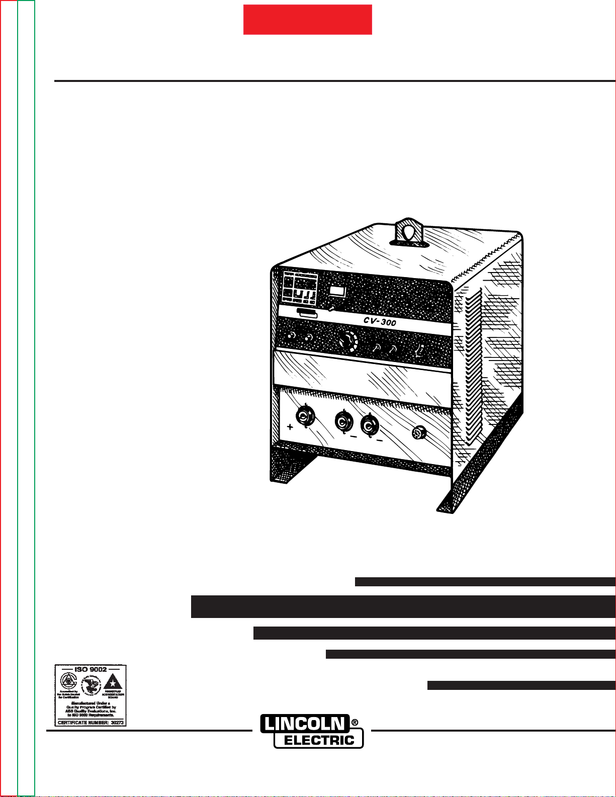
PHYSICAL DIMENSIONS
HEIGHT WIDTH DEPTH LIFT HOOK WEIGHT
ADD
21.5” 19.5” 27.0” 3.12” 300 lbs.
(546mm) (495mm) (686mm) (80mm) (136 Kg.)
Return to Master TOC Return to Master TOC Return to Master TOC Return to Master TOC
Return to Section TOC Return to Section TOC Return to Section TOC Return to Section TOC
IDEALARC CV-300
Page 9
A-2
INSTALLATION
A-2
Read entire Installation Section before installing
the IDEALARC CV-300.
SAFETY PRECAUTIONS
WARNING
ELECTRIC SHOCK can kill.
• Only qualified personnel should
install this machine.
• Turn the input power OFF at the disconnect switch or fuse box before
working on the equipment.
• Turn the Power switch on the CV-300 “OFF”
before connecting or disconnecting output
cables, wire feeder or remote connections, or
other equipment.
• Do not touch electrically hot parts.
• Always connect the IDEALARC CV-300 grounding terminal (located on the welder base near
the reconnect panel) to a good electrical earth
ground.
____________________________________
Follow these guidelines when stacking:
1. Select a firm, level surface capable of supporting
the total weight of up to three machines.
2. Set the bottom machine in place.
3. Stack the second machine on top of it by aligning
the two holes in the base rails of the second
machine with the two pins on top of the bottom
machine.
4. Repeat process for third machine.
NOTE: The machines must be stacked with the Case
Front of each machine flush with each other. See
Figure A.1.
STACKING HOLE
SELECT PROPER LOCATION
The IDEALARC CV-300 can be used indoors or outdoors. It has an IP-23 degree of protection.
Place the IDEALARC CV-300 where clean, cooling air
can freely circulate in through the side louvers and out
through the rear louvers. Dirt, dust, or any foreign
material that can be drawn into the machine should be
kept at a minimum. Not following these precautions
can result in the nuisance shutdown of the machine
because of excessive operating temperatures.
STACKING
Three IDEALARC CV-300 machines can be stacked.
DO NOT stack more than three machines in one
grouping.
DO NOT stack the IDEALARC CV -300 on another type
of machine.
STACKING PIN
FIGURE A.1 - Stacking IDEALARC CV-300
machines.
TILTING
The IDEALARC CV-300 must be placed on a stable,
level surface so it will not topple over. Do not place the
machine on an incline.
Return to Master TOC Return to Master TOC Return to Master TOC Return to Master TOC
Return to Section TOC Return to Section TOC Return to Section TOC Return to Section TOC
IDEALARC CV-300
Page 10
A-3
INSTALLATION
INPUT ELECTRICAL CONNECTIONS
WARNING
All input power must be electrically
disconnected before proceeding.
____________________________________
A-3
CASE BACK
RIGHT CASE
SIDE PANEL
(REMOVED)
1. Before starting the installation, check with the local
power company to determine if there is any question about whether your power supply is adequate
for the voltage, amperes, phase, and frequency
specified on the welder nameplate. Have a qualified electrician connect the input leads to L1, L2,
and L3 on the input reconnect panel in compliance
with the National Electrical Code, all local codes,
and the connection diagram located on the inside
of the Right Case Side Panel. This welder can
operate on a three-phase AC voltage supply only.
2. Models that have multiple input voltages specified
on the nameplate (e.g., 208/230) are shipped connected for the highest voltage. If the welder is to
be operated at a lower voltage, it must be reconnected according to the instructions on the inside
of the removable Right Case Side Panel. See the
Reconnect Section of this manual for details on
reconnecting the machine to operate at different
voltages.
3. Be sure the voltage, phase, and frequency of the
input power is as specified on the machine rating
plate. See Figure A.2 for the location of the
machine's input cord entry and Reconnect Panel.
4. Access to the input reconnect panel is achieved by
removing the Right Case Side Panel of the CV-300
on the ON/OFF POWER SWITCH side of the
machine.
5. The frame of the welder must be grounded. A
ground terminal marked with the symbol ( ) is
located at the bottom of the input box to ground the
welder. See the National Electrical Code for
details on proper grounding methods.
ECONNECT
ANEL
INPUT CABLE
& CABLE CLAMP
FIGURE A.2 - Input Power Cable Entry Connections
and Reconnect Panel location.
FUSE AND WIRE SIZES
Protect the input circuit with the super lag fuses or
delay type circuit breakers listed on the
Specifications
being used. Delay type circuit breakers may be used.
The tripping action of delay type circuit breakers
decreases as the magnitude of the current increases.
They are also called inverse time or thermal/magnetic
circuit breakers.
DO NOT use fuses or circuit breakers with a lower amp
rating than recommended. This can result in "nuisance" tripping caused by inrush current even when
machine is not being used for welding at high output
currents.
Use input and grounding wire sizes that meet local
electrical codes or see the
page in this manual.
page of this manual for the machine
Technical Specifications
Technical
Return to Master TOC Return to Master TOC Return to Master TOC Return to Master TOC
Return to Section TOC Return to Section TOC Return to Section TOC Return to Section TOC
IDEALARC CV-300
Page 11
A-4
INSTALLATION
RECONNECT PROCEDURE
Multiple voltage machines are shipped connected to
the highest input voltage listed on the machine's rating
plate. Before installing the machine, check that the
Reconnect Panel is connected for the proper voltage.
CAUTION
Failure to follow these instructions can cause
immediate failure of components within the
machine.
____________________________________
To reconnect a dual or triple voltage machine to a different voltage, change the position of the leads or links
on the Reconnect Panel based the type of machine.
Follow The Input Supply Connection Diagram located
on the inside of the Right Case Side Panel.
A-4
For dual voltage machines, see Figure A.3.
For 208/230/440 voltage machines, see Figure A.4.
For 230/460/575 voltage machines, see Figure A.5.
CONNECTION FOR
UNDER 300 VOLTS
INPUT LINES
L3
L2
L1
GROUND
CONNECTION FOR
OVER 300 VOLTS
INPUT LINES
L3
L2
L1
GROUND
1. Check nuts on terminal board for tightness,
then place the five copper links in the positions shown. Secure the links tightly with
the nine hex nuts provided.
2. Connect L1, L2, & L3 as shown.
3. Connect terminal marked to ground terminal per National Electrical Code.
1. Check nuts on terminal board for tightness,
then place the copper links in the positions
shown. Double up the extra links in two of
the positions to save the extra links for
future use. Secure the links tightly with the
six hex nuts provided, then secure the
remaining three hex nuts in place for future
use.
2. Connect L1, L2, & L3 as shown.
3. Connect terminal marked to ground terminal per National Electrical Code.
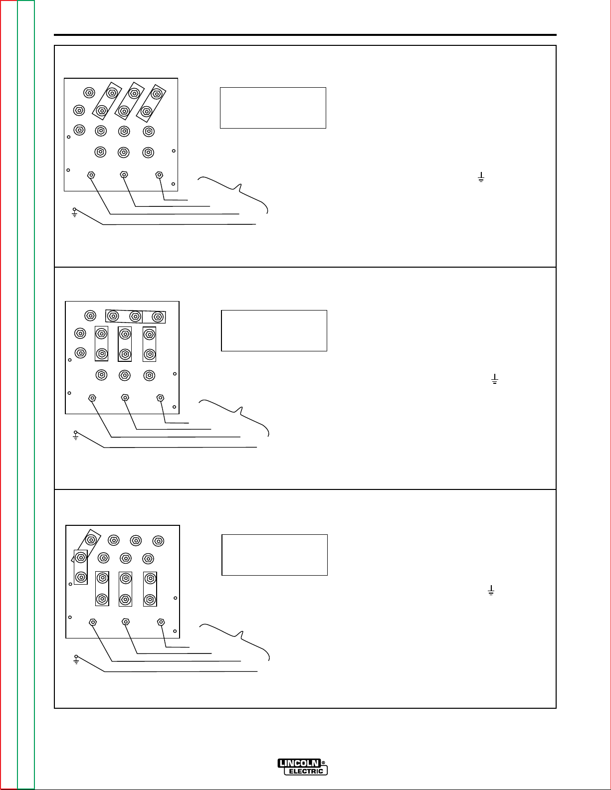
FIGURE A.3 - Reconnect Diagram For Dual Voltage Machines.
Return to Master TOC Return to Master TOC Return to Master TOC Return to Master TOC
Return to Section TOC Return to Section TOC Return to Section TOC Return to Section TOC
IDEALARC CV-300
Page 12
A-5
INSTALLATION
CONNECTION FOR
460 VOLTS 60HZ.
A-5
1. Check nuts on terminal board for tightness, then place the copper links in the
positions shown. Double up the links in
two of the positions to save them for
future use. Secure the links tightly with
the hex nuts provided. Secure the
remaining hex nuts in place for future
use.
uv w
uv w
L3
L3
INPUT LINES
L2
L1
GROUND
CONNECTION FOR
230 VOLTS 60HZ.
INPUT LINES
L2
L1
GROUND
2. Connect L1, L2, & L3 as shown.
3. Connect terminal marked to ground terminal per National Electrical Code.
1. Check nuts on terminal board for tightness, then place the copper links in the
positions shown. Secure the links tightly with the hex nuts provided.
2. Connect L1, L2, & L3 as shown.
3. Connect terminal marked to ground
terminal per National Electrical Code.
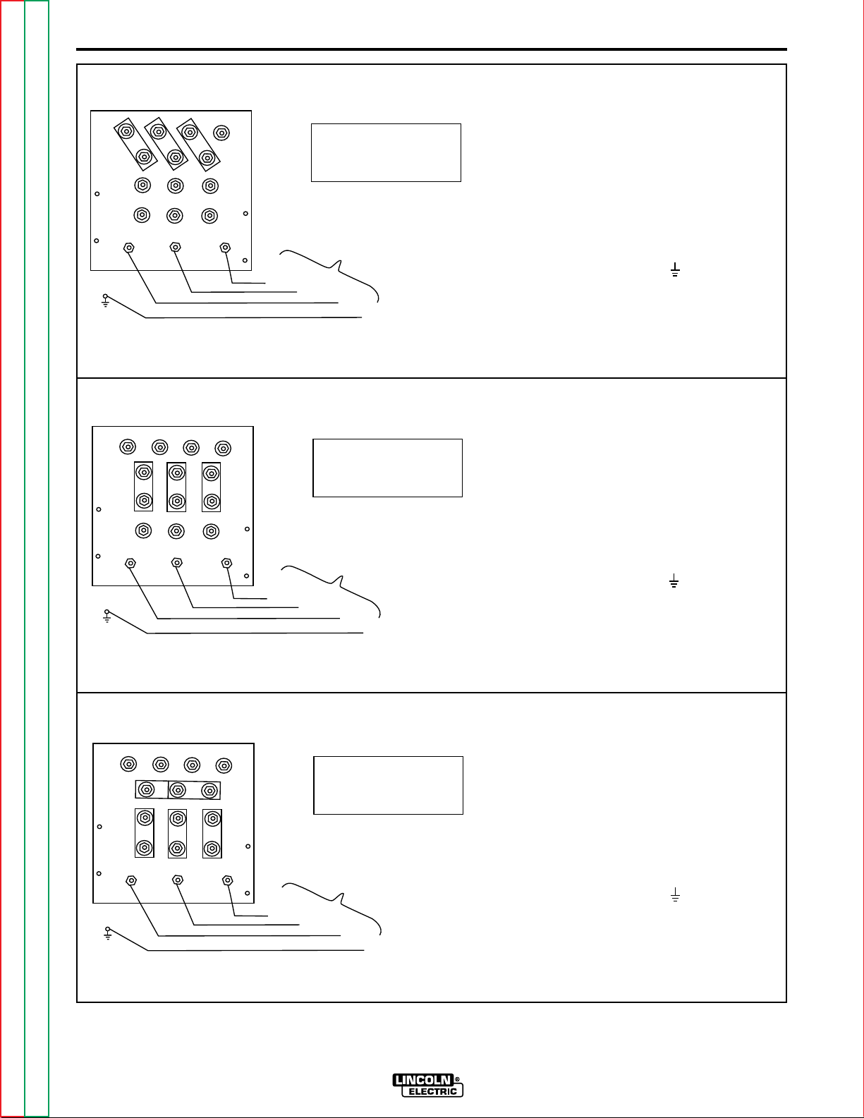
FIGURE A.4 - Reconnect Diagram For 208/230/440 voltage machines.
Return to Master TOC Return to Master TOC Return to Master TOC Return to Master TOC
Return to Section TOC Return to Section TOC Return to Section TOC Return to Section TOC
uv w
L3
CONNECTION FOR
208 VOLTS 60HZ.
INPUT LINES
L2
L1
GROUND
IDEALARC CV-300
1. Check nuts on terminal board for tightness, then place the copper links in the
positions shown. Secure the links tightly
with the hex nuts provided.
2. Connect L1, L2, & L3 as shown.
3. Connect terminal marked to ground
terminal per National Electrical Code.
Page 13
A-6
INSTALLATION
CONNECTION FOR
575 VOLTS 60HZ.
A-6
1. Check nuts on terminal board for tightness, then place the copper links in the
positions shown. Double up the links in
two of the positions to save them for future
use. Secure the links tightly with the hex
nuts provided. Secure the remaining hex
nuts in place for future use.
uv w
uv w
L3
L3
INPUT LINES
L2
L1
GROUND
CONNECTION FOR
460 VOLTS 60HZ.
INPUT LINES
L2
L1
GROUND
2. Connect L1, L2, & L3 as shown.
3. Connect terminal marked to ground terminal per National Electrical Code.
1. Check nuts on terminal board for tightness, then place the copper links in the
positions shown. Double up the links in
two of the positions to save them for future
use. Secure the links tightly with the hex
nuts provided. Secure the remaining hex
nuts in place for future use.
2. Connect L1, L2, & L3 as shown.
3. Connect terminal marked to ground terminal per National Electrical Code.
FIGURE A.5 - Reconnect Diagram for 230/460/575 voltage machines.
Return to Master TOC Return to Master TOC Return to Master TOC Return to Master TOC
Return to Section TOC Return to Section TOC Return to Section TOC Return to Section TOC
uv w
L3
CONNECTION FOR
230 VOLTS 60HZ.
INPUT LINES
L2
L1
GROUND
IDEALARC CV-300
1. Check nuts on terminal board for tightness, then place the copper links in the
positions shown. Secure the links tightly
with the hex nuts provided.
2. Connect L1, L2, & L3 as shown.
3. Connect terminal marked to ground terminal per National Electrical Code.
Page 14
A-7
INSTALLATION
A-7
CONNECT OUTPUT CABLES
WARNING
ELECTRIC SHOCK CAN KILL.
TURN THE POWER SWITCH ON THE
CV-300 OFF BEFORE MAKING CONNECTIONS TO THE OUTPUT TERMINALS OR WIRE FEEDER RECEPTACLE.
____________________________________
Note: Output cables must have Magnum Twist-Mate
plugs for connection to the CV-300. Order K852-95
Magnum Twist-Mate plugs (2 required) for connecting
2/0-3/0 (70-95 mm2) cables. Order K852-95 for connecting 2/0-3/0 (70-95 mm2) cables. Refer to
Mate Cable Plug Installation Instructions
this manual.
1. Connect the positive output lead to the terminal
marked (+).
2. Connect the negative output lead to either the low
inductance terminal marked ( ) or the high inductance terminal marked ( ).
Note: Use the proper cable sizes for the work and electrode cables as shown in the following table.
CABLE SIZES FOR COMBINED LENGTHS OF COPPER ELECTRODE AND WORK CABLE
Twist-
section of
INSTALLATION OF WIRE FEEDERS
Follow the instructions for the wire feeder that will be
used. See the
Accessories
section of this manual.
TWIST-MATE CABLE PLUG
INSTALLATION INSTRUCTIONS
WARNING
ELECTRIC SHOCK CAN KILL.
TURN THE POWER SWITCH OF THE
WELDING POWER “OFF” BEFORE
INSTALLING PLUGS ON CABLES OR
WHEN CONNECTING OR DISCONNECTING PLUGS TO WELDING
POWER SOURCE.
____________________________________
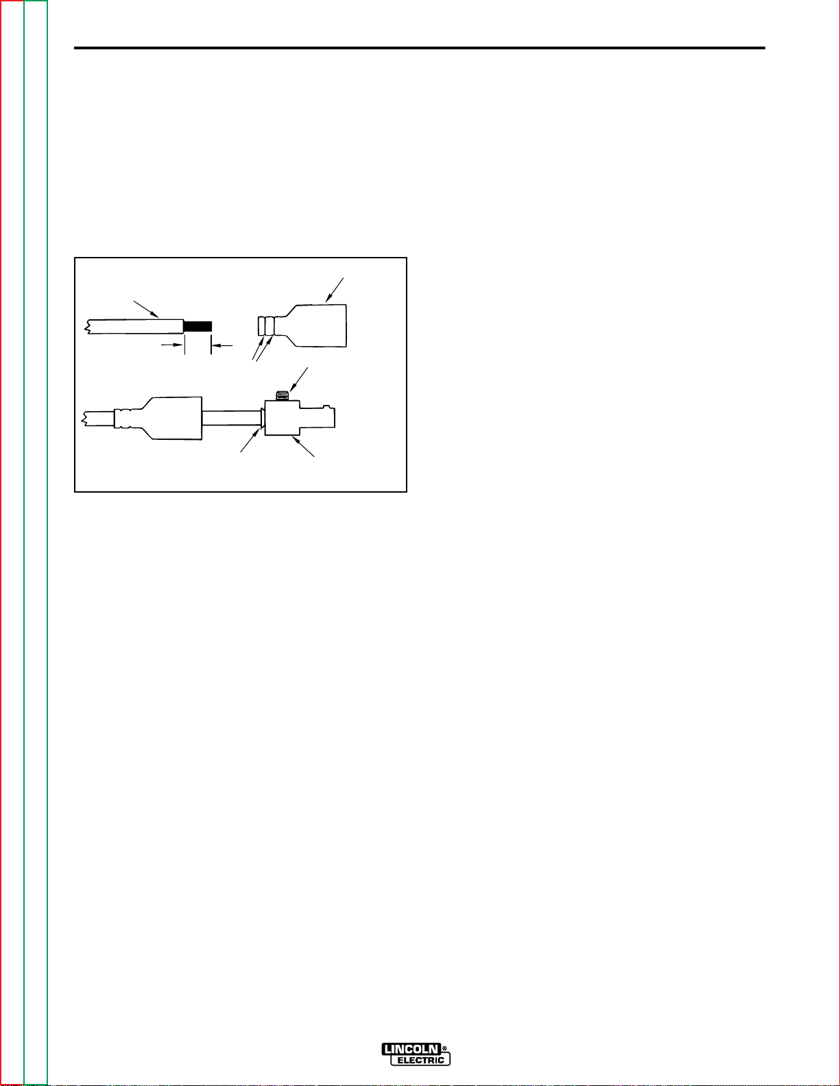
1 Check that the connector boot is marked for the
appropriate cable size per table below; and strip
the cable jacket to length specified:
American
Boot Marking
35-50
50-70
70-95
(Metric)
Range Cable
Size
#2-#1 (35-50mm2)
1/0-2/0(50-70mm2)
2/0-3/0(70-95mm2)
Cable Skin
Length
1 inch (25.4mm)
1 inch (25.4mm)
1.5 inch (38.1mm)
Machine Size
300/100%
(400/60%)
PARALLELING
The CV-300 is not designed to be paralleled with any
other power source.
INSTALLATION OF FIELD
INSTALLED ACCESSORIES
For installation of compatible field installed accessories, refer to the instructions included with those
accessories.
Return to Master TOC Return to Master TOC Return to Master TOC Return to Master TOC
Return to Section TOC Return to Section TOC Return to Section TOC Return to Section TOC
Lengths up to
150 Ft.
2/0 (70mm2)
Lengths from
150 to 200 Ft.
3/0 (95mm2)
IDEALARC CV-300
2. If necessary, trim the cable end of the boot at
groove(s) to match the cable diameter. See Figure
A.6. Boot must fit tightly enough to seal around
outside diameter of cable.
NOTE: Some boots are designed to accommodate different cable diameters without trimming. These boots
do not have grooves at the cable end. Soap or other
non petroleum based lubricant will help to slide the
boot over the cable.
3. Slide the rubber boot onto cable end. See Figure
A.6.
4. Slide the copper tube into the brass plug. See
Figure A.6.
5. Insert cable into the copper tube. See Figure A.6.
Page 15
A-8
INSTALLATION
6. Tighten the set screw(s) to collapse the tube. The
screw(s) must apply firm pressure against welding
cable. The top of the set screw(s) will be nearly
flush or below the surface of the brass plug after
tightening.
7. Slide rubber boot over brass plug. The rubber boot
must be positioned to completely cover all electrical surfaces after the plug is locked into the receptacle.
BOOT
WELDING CABLE
SEE
ABOVE
TRIM
SET SCREW
(70-95 SIZE MAY HAVE
2 SET SCREWS)
A-8
COPPER TUBE
BRASS PLUG
FIGURE A.6 - Installing Twist-Mate Cable Plug.
Return to Master TOC Return to Master TOC Return to Master TOC Return to Master TOC
Return to Section TOC Return to Section TOC Return to Section TOC Return to Section TOC
IDEALARC CV-300
Page 16

NOTES
Return to Master TOC Return to Master TOC Return to Master TOC Return to Master TOC
Return to Section TOC Return to Section TOC Return to Section TOC Return to Section TOC
IDEALARC CV-300
Page 17

OPERATION
TABLE OF CONTENTS
- OPERATION SECTION -
OPERATION SECTION ............................................ Section B
Safety Instructions ............................................................B-1
General Description..........................................................B-1
Recommended Processes and Equipment ......................B-2
Machine Capability...........................................................B-2
Limitations........................................................................B-2
Controls and Settings.......................................................B-3
Power Switch...............................................................B-3
Wire Feeder Voltmeter Switch.....................................B-3
Local/Remote Switch...................................................B-3
Voltage Adjustment Control Knob ...............................B-3
115-Volt Circuit Breaker...............................................B-4
42-Volt Circuit Breaker................................................B-4
Volts/Amps Switch.......................................................B-4
Digital Voltmeter/Ammeter...........................................B-4
Thermal Protection Indication Light.............................B-4
Wire Feeder Receptacle..............................................B-4
High Inductance Negative Output Connection............B-4
Low Inductance Negative Connector..........................B-4
Positive Output Connector ..........................................B-4
Operating Steps ...............................................................B-5
Starting the Machine ...................................................B-5
Adjusting the Output Voltage using the Digital Meter.B-5
Using Local/Remote Switch Operation .......................B-5
Using Auxiliary Power..................................................B-5
Machine and Circuit Protection........................................B-6
Return to Master TOC Return to Master TOC Return to Master TOC Return to Master TOC
IDEALARC CV-300
Page 18
B-1
OPERATION
B-1
Read and understand this entire section before
operating your Idealarc CV-300.
SAFETY INSTRUCTIONS
WARNING
ELECTRIC SHOCK can kill.
• Do not touch electrically live parts such
as output terminals or internal wiring.
• Insulate yourself from the work and
ground.
• Always wear dry insulating gloves.
____________________________________
FUMES AND GASES
can be dangerous.
• Keep your head out of fumes.
• Use ventilation or exhaust to
remove fumes from breathing
zone.
CAUTION
When using a CV-300 power source with wire feeders, there will be a small spark if the electrode contacts the work or ground within several seconds
after releasing the trigger.
When use with some wire feeders with the electrical trigger interlock in the ON position, the arc
might restart if the electrode touches the work or
ground during these several seconds.
____________________________________
GENERAL DESCRIPTION
Product Description
The IDEALARC CV-300 is a constant voltage DC
power source designed for the GMAW process with
limited FCAW capability. It features an industrial rating
of 300 amps, 32 volts, at 100% duty cycle. It complies
with the requirements for a NEMA Class I (100) power
source. It is available from the factory in one model
only, with no options other than input voltage or frequency.
____________________________________
WELDING, CUTTING and
GOUGING SPARKS
can cause fire or explosion
• Keep flammable material away.
• Do not weld, cut or gouge on
containers that have held com-
bustibles.
____________________________________
ARC RAYS
can burn.
• Wear eye, ear and body
protection.
____________________________________
Only qualified personnel should operate this equipment. Observe all safety information throughout this
manual.
No options are available other than input voltage.
The IDEALARC CV-300 includes the following fea-
tures:
• Two inductance positions: operator can
choose the optimum output characteristics.
• Solid State Output Contactor: no noise, no
moving parts to wear.
• Digital Voltmeter/Ammeter is standard.
• 42 VAC, 10 amp auxiliary power available for
the wire feeder.
• Circuit breaker protected.
• 115 VAC, 5 amp auxiliary power available for
the wire feeder; circuit breaker protected.
Return to Master TOC Return to Master TOC Return to Master TOC Return to Master TOC
Return to Section TOC Return to Section TOC Return to Section TOC Return to Section TOC
IDEALARC CV-300
Page 19

B-2
OPERATION
B-2
• Magnum Twist-Mate output receptacles.
• Single MS-type (14-pin) connection for wire
feeder.
• Solid state controls, with line voltage compensation.
• Optional remote control capability.
• Simple controls - easy to operate.
• Electronic and thermostatic protection from
overloads.
• Submersion dipping of assembled transformer, choke, and rectifier in special
sealing/insulating material that gives extra protection against moisture and corrosive atmospheres.
• Microprocessor based Control PC Board has
built-in diagnostic routines.
• Compact size, requires only 19" x 26"of space.
• Modular construction for easy servicing.
MACHINE CAPABILITY
Duty Cycle
(10-Minute
Period)
100%
60%
Amps.
300
400
Volts
32
36
LIMITATIONS
The CV-300 is intended only for use with the following
FCAW electrodes:
NR-152
NR-211
NR-203 Ni 1%
NS-3M
Outershield 70 and 71
The machine has been designed primarily for the
GMAW process. The results with FCAW electrodes
other than those listed may or may not be satisfactory.
• Recessed panels protect output terminals and
controls.
• Large safety margins and protective circuits
protect rectifiers from transient voltages and
high currents.
RECOMMENDED PROCESSES AND
EQUIPMENT
The CV-300 is capable of solid wire welding within the
rated output capacity of the machine. It is capable of
welding with the following flux-cored wires:
NR-152
NR-211
NS-3M
NR-203 Ni 1%
Outershields 70 and 71
The CV-300 is recommended for use with the following
wire feeders:
LN-7
LN-742
LN-25
Return to Master TOC Return to Master TOC Return to Master TOC Return to Master TOC
Return to Section TOC Return to Section TOC Return to Section TOC Return to Section TOC
IDEALARC CV-300
Page 20
B-3
OPERATION
CONTROLS AND SETTINGS
All operator controls and welding connections are
located on the Case Front of the machine. See Figure
B.1 for the location of each control and connection.
B-3
7
6
8
5
4
3
9
2
1
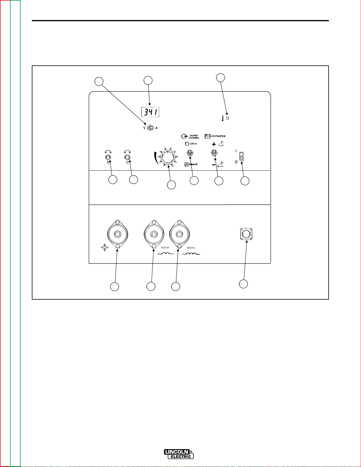
FIGURE B.1- CV-300 Operator Controls and
Connections.
1. ON/OFF POWER SWITCH - Two position
toggle switch that controls input power to the
machine.
2. WIRE FEEDER VOLTMETER SWITCH -
This switch selects the polarity of the wire feeder
voltmeter, if so equipped. When welding electrode
positive (MIG, Outershield and some Innershield
processes) set the switch to "+".
When welding electrode negative (most Innershield
electrodes), set the switch to "-".
Return to Master TOC Return to Master TOC Return to Master TOC Return to Master TOC
Return to Section TOC Return to Section TOC Return to Section TOC Return to Section TOC
13
12
11
NOTE: This switch has no effect on the welding polarity. In fact, if the wire feeder being used does not have
a voltmeter, the setting of this switch has no effect.
3. LOCAL/REMOTE SWITCH - When switch is
4. VOLTAGE ADJUSTMENT CONTROL
IDEALARC CV-300
10
in the LOCAL position, the welding voltage is controlled at the CV-300. When the switch is the
REMOTE position, the welding voltage is controlled remotely by a remote output control.
KNOB - Controls the CV-300 output voltage.
Page 21

B-4
OPERATION
B-4
5. 115-VOLT CIRCUIT BREAKER - Protects
the 115-volt 31-32 circuit in the wire feeder receptacle from overloads and shorts. If this circuit
breaker opens, the CV-300 will operate normally.
However, any equipment powered by the 115-volt
circuit will not operate.
NOTE: Earlier models may have one 10amp circuit
breaker for both the 115 and 42 volt AC circuits.
6. 42-VOLT CIRCUIT BREAKER - Protects
the 42-volt 41-42 circuit in the wire feeder receptacle from overloads and shorts. If this circuit breaker opens, the CV-300 will operate normally.
However, any equipment powered by the 42-volt
circuit will not operate.
7. VOLTS/AMPS SWITCH - When in the “V”
position, output voltage is displayed on the digital
meter. When in the “A” position, the output current
is displayed on the digital meter.
8. DIGITAL VOLTMETER/AMMETER - The
meter displays the CV-300 output current or the
arc voltage.
11.HIGH INDUCTANCE NEGATIVE OUTPUT TERMINAL - The high inductance con-
nection is typically used for short arc welding heavier welds or when using 75% Argon/25% CO
shielding gas. This connection produces a softer
arc and a flatter bead with more wash-in than the
low inductance connection. A spray type transfer
is possible with either connection.
12.LOW INDUCTANCE NEGATIVE OUTPUT TERMINAL - The low inductance connec-
tion is typically used for short arc welding of mild
steel, particularly on thin materials or when using
CO shielding gas.
13.POSITIVE OUTPUT TERMINAL
NOTE: The positive and negative output terminals are
Magnum Twist-Mate receptacles. Insert a matching
Twist-Mate plug and twist clockwise to engage.
For GMAW processes, and some FCAW processes,
the positive output connection goes to the wire feeder.
One of the negative output connections goes directly to
the work.
NOTE: Due to voltage drops in the welding cables and
at the cable connection points, the actual arc voltage
may be lower than that displayed on the voltmeter.
Use welding cables of the proper capacity and make
sure all connections are tight to minimize this effect.
9. THERMAL PROTECTION INDICATION
LIGHT - When lit, the light indicates that the pro-
tection thermostat has activated. The digital meter
will display "E10" when this occurs. The machine
will not operate. When the light turns off, the
machine has cooled sufficiently to provide welding
output power again.
NOTE: Leaving the ON/OFF POWER SWITCH in the
"ON" position will result in the most rapid cooling.
10. WIRE FEEDER RECEPTACLE - This is a
14-pin MS style receptacle. It provides connections for auxiliary power, contactor closure, remote
output control, wire feeder voltmeter sense lead,
and ground.
Return to Master TOC Return to Master TOC Return to Master TOC Return to Master TOC
Return to Section TOC Return to Section TOC Return to Section TOC Return to Section TOC
IDEALARC CV-300
Page 22

B-5
OPERATION
B-5
OPERATING STEPS
STARTING THE MACHINE
Turn the ON/OFF POWER SWITCH to the ON position. See Figure B.1.
ADJUSTING THE OUTPUT VOLTAGE
USING THE DIGITAL METER
The digital meter in the CV-300 incorporate a voltage
preset function. This allows the operator to set the
desired welding voltage before striking an arc. The
digital meter can also display welding current.
To make use of the voltage preset function, the
Volts/Amps switch must be in the "Volts" position. Turn
the Voltage Adjust knob until the digital meter displays
the desired welding voltage. (See below if an external
power source remote control is installed.)
NOTE: When an arc is struck, the digital meter displays the actual welding voltage, as measured at the
CV-300 output terminals. The arc voltage at the electrode may be as much as two volts different from the
CV-300 output terminal voltage. This is due to voltage
drops present in the welding cables, cable connections, and welding gun. To minimize these drops, use
cables of adequate capacity, and make sure all connections are clean and tight. Because of these voltage
drops, you may have to preset the CV-300 for a slightly higher welding voltage than your procedure calls for.
USING AUXILIARY POWER
A 42-volt AC auxiliary power source required for some
wire feeders is available through the wire feeder receptacle. A10-amp circuit breaker protects the 42-volt circuit from overloads.
The CV-300 machine can also supply 115 volt AC auxiliary power through the wire feeder receptacle. A 5amp circuit breaker protects the 115 volt circuit from
overloads.
NOTE: Earlier models may have one 10amp circuit
breaker for both the 115 and 42 volt AC circuits.
NOTE: Do not use circuits 2 or 4 for control of auxiliary loads because the 2-4 circuit is isolated from the
31-32 and 41-42 circuits.
CAUTION
Note that some types of equipment, especially
pumps and large motors, have starting currents
which are significantly higher than their running
current. These higher starting currents may cause
the circuit breaker to open. If this situation occurs,
the user should refrain from using the CV-300 auxiliary power for that equipment.
____________________________________
To read welding current, set the Volts/Amps switch to
the "Amps" position. The welding current will be displayed whenever an arc is struck.
USING LOCAL/REMOTE SWITCH
OPERATION
If controlling the voltage at the CV-300, the
Local/Remote switch must be in the "Local" position.
The Voltage Adjust Knob on the front panel can be
used to adjust the CV-300 output. (The remote control,
even if connected, will have no effect if the switch is in
the "Local" position).
To use a remote control, such as the K857, place the
Local/Remote switch in the "Remote" position. The
remote control now controls the output voltage. This
control may be adjusted while welding to change the
CV-300 output.
Return to Master TOC Return to Master TOC Return to Master TOC Return to Master TOC
Return to Section TOC Return to Section TOC Return to Section TOC Return to Section TOC
IDEALARC CV-300
Page 23

B-6
OPERATION
MACHINE AND CIRCUIT
PROTECTION
The CV-300 Control PC Board has built-in diagnostic
routines to alert the operator when trouble exists.
When a trouble condition occurs, the CV-300 meter will
display an error code, in the form “EXX”’ where “XX”
refers to a specific error. See
Section
The power source is thermostatically protected against
overload or insufficient cooling. If the machine is overloaded, the thermostat will open, thermal protection
indicator light will turn on, and the output will be zero.
The fan will continue to run and auxiliary power will still
be available. The thermostat will remain open until
machine cools, at which time it will close and the output will again be available.
The CV-300 is electronically protected against overloads and accidental short circuits. The overload protection circuit automatically reduces the output current
to a safe value when an overload is detected. If the circuitry senses a short circuit, it will shut off the CV-300
output. The short circuit protection circuit can be reset
by turning the CV-300 Power Switch OFF for at least
10 seconds. Remove the short before turning the
Power Switch ON again.
for an explanation of the error codes.
Troubleshooting
B-6
Return to Master TOC Return to Master TOC Return to Master TOC Return to Master TOC
Return to Section TOC Return to Section TOC Return to Section TOC Return to Section TOC
IDEALARC CV-300
Page 24

NOTES
Return to Master TOC Return to Master TOC Return to Master TOC Return to Master TOC
Return to Section TOC Return to Section TOC Return to Section TOC Return to Section TOC
IDEALARC CV-300
Page 25

ACCESSORIES
TABLE OF CONTENTS
- ACCESSORIES SECTION -
ACCESSORIES SECTION ....................................... Section C
Field Installed Accessories...............................................C-1
Remote Voltage Control (K857) ..................................C-1
One Cylinder Undercarriage (K835) ...........................C-1
Two Cylinder Undercarriage (K874)............................C-1
Wire Feeder Swivel Mount (K178-1) ...........................C-1
Universal Adapter (K867)............................................C-1
Connecting Wire Feeder to the CV-300...........................C-1
LN-7 to CV-300...........................................................C-1
LN-25 to CV-300.........................................................C-2
LN-742 to CV-300.......................................................C-2
Connecting Remote Control (K857) to CV-300................C-2
Return to Master TOC Return to Master TOC Return to Master TOC Return to Master TOC
IDEALARC CV-300
Page 26

C-1
ACCESSORIES
C-1
FIELD INSTALLED ACCESSORIES
NOTE: The instructions for installing and operating
each accessory is included with the accessory.
REMOTE VOLTAGE CONTROL (K857)
The K857 Remote Voltage Control consists of a control
box with 25 feet (7.6 m) of four conductor cable.
Installation of a K857 Remote Voltage Control in the
CV-300 requires a K864 Remote Control Adapter.
Refer to the instructions provided with the K857 for
hookup to the CV-300. When properly connected and
the CV-300 LOCAL/REMOTE SWITCH in the
"Remote" position, the K857 functions the same as the
CV-300 Voltage Adjust control. This enables minimum
to maximum output voltage adjustment of the CV-300.
ONE CYLINDER UNDERCARRIAGE
(K835)
The undercarriage includes front casters, a handle, a
bracket, and a rear wheeled platform that is capable of
carrying one gas cylinder. The CV-300 lifting eye is not
functional with the K835 undercarriage installed.
CONNECTING WIRE FEEDER TO
THE CV-300
Based on the type of wire feeder being used follow the
directions for connecting it to the CV-300.
The CV-300 is intended for use with the LN-7, LN-742,
and LN-25 wire feed units. Use the Cables/Kits listed
below to make connection easily:
LN-7/LN-7GMA Requires K480 Input Cable
LN-25
LN-25 w/K444-1
Remote Voltage
Control Kit
LN-742/LN-742H Requires K591 Input Cable
Requires K484 Jumper
Plug Kit
Requires K464 Remote
Control Adapter and K484
Jumper Plug Kit
TWO CYLINDER UNDERCARRIAGE
(K874)
The two-cylinder undercarriage platform type can
accommodate either one or two gas bottles, or one gas
bottle and a Magnum water cooler. The CV-300 lifting
eye is not functional when the K874 undercarriage is
installed.
WIRE FEEDER SWIVEL MOUNT (K178-1)
This allows an LN-7 or LN-742 to be securely mounted
on the roof of a CV-300.
UNIVERSAL ADAPTER (K867)
This provides a means of connecting auxiliary equipment to the wire feeder receptacle on the CV-300
power source. It consists of a 14-pin MS-type
(Amphenol) plug with 8-inch (0.2 meter) long flex
leads, one for each circuit present in the wire feeder
receptacle. This adapter is not required when using a
standard Lincoln Electric wire feeder input cable, such
as a K480.
LN-7 TO CV-300
1. Turn the ON/OFF POWER SWITCH to OFF.
2. Connect the LN-7 control cable to the wire feeder
receptacle on the CV-300.
3. Connect the work and electrode cables.
a. Connect the positive output lead to the termi-
nal marked (+).
b. Connect the negative output lead to either the
low inductance terminal marked ( ) or the high
inductance terminal marked ( ).
Return to Master TOC Return to Master TOC Return to Master TOC Return to Master TOC
Return to Section TOC Return to Section TOC Return to Section TOC Return to Section TOC
IDEALARC CV-300
Page 27

C-2
ACCESSORIES
C-2
LN-25 TO CV-300
1. Turn the ON/OFF POWER SWITCH to OFF.
2. Plug a K484 jumper plug into the CV-300 wire
feeder receptacle.
3. Connect the work and electrode cables.
a. Connect the positive output lead to the termi-
nal marked (+).
b. Connect the negative output lead to either the
low inductance terminal marked ( ) or the high
inductance terminal marked ( ).
WARNING
The output terminals are energized at all times
when the K484 is plugged in.
3. Plug the K857 Remote Control into the 6-pin
receptacle of the K864 adapter. If possible, tape
the Remote cable to the heavy output leads, so
they can protect the smaller Remote Control cable
from damage and abuse.
____________________________________
LN-742 TO CV-300
1. Turn the ON/OFF POWER SWITCH to OFF.
2. Connect the LN-742 control cable to the wire feeder receptacle on the CV-300.
3. Connect the work and electrode cables.
a. Connect the positive output lead to the termi-
nal marked (+).
b. Connect the negative output lead to either the
low inductance terminal marked ( ) or the high
inductance terminal marked ( ).
CONNECTING REMOTE CONTROL (K857)
TO CV-300
1. Turn the ON/OFF POWER SWITCH to OFF.
NOTE: The K864 Remote Control Adapter is required
to install the K857.
2. Plug the K864 Remote Control Adapter into the
power source's 14-pin receptacle.
Return to Master TOC Return to Master TOC Return to Master TOC Return to Master TOC
Return to Section TOC Return to Section TOC Return to Section TOC Return to Section TOC
IDEALARC CV-300
Page 28

NOTES
Return to Master TOC Return to Master TOC Return to Master TOC Return to Master TOC
Return to Section TOC Return to Section TOC Return to Section TOC Return to Section TOC
IDEALARC CV-300
Page 29

MAINTENANCE
TABLE OF CONTENTS
- MAINTENANCE SECTION -
MAINTENANCE SECTION ...................................... Section D
Safety Precautions...........................................................D-1
Routine and Periodic Maintenance..................................D-1
Component Locations.................................................D-2
Return to Master TOC Return to Master TOC Return to Master TOC Return to Master TOC
IDEALARC CV-300
Page 30

D-1
MAINTENANCE
SAFETY PRECAUTIONS
WARNING
• Have a qualified technician do the maintenance
and troubleshooting work.
• Disconnect input power at main input supply
prior to working inside machine.
____________________________________
Read the Safety Precautions in the front of this manual before working on this machine.
ROUTINE AND PERIODIC
MAINTENANCE
1. Disconnect input AC power supply lines to the
machine before performing periodic maintenance,
tightening, cleaning, or replacing parts. See
Figure D.1.
D-1
Perform the following daily:
1. Check that no combustible materials are in the
welding or cutting area or around the machine.
2. Remove any debris, dust, dirt, or materials that
could block the air flow to the machine for cooling.
3. Inspect the electrode cables for any slits, punctures in the cable jacket, or any condition that
would affect the proper operation of the machine.
Perform Periodically:
Clean the inside of the machine with low pressure air
stream. Clean the following parts. Refer to Figure D.1.
Main transformer and choke.
Electrode and work cable connections.
SCR rectifier bridge and heat sink fins.
Control board.
Fan Motor Assembly.
NOTE: The fan motor has sealed bearings which
require no maintenance.
Return to Master TOC Return to Master TOC Return to Master TOC Return to Master TOC
Return to Section TOC Return to Section TOC Return to Section TOC Return to Section TOC
IDEALARC CV-300
Page 31

D-2
MAINTENANCE
D-2
COVER
ASSEMBLY
MAIN TRANSFORMER
AND CHOKE ASSEMBLY
CAPACITOR AND
SCR BRIDGE RECTIFIER
ASSEMBLY
CASE BACK
ASSEMBLY
CASE FRONT
ASSEMBLY
(CONTROL BOARD
LOCATED ON BACK)
Return to Master TOC Return to Master TOC Return to Master TOC Return to Master TOC
Return to Section TOC Return to Section TOC Return to Section TOC Return to Section TOC
BASE AND FAN
MOTOR ASSEMBLY
Figure D.1 - Component Locations.
IDEALARC CV-300
Page 32

NOTES
Return to Master TOC Return to Master TOC Return to Master TOC Return to Master TOC
Return to Section TOC Return to Section TOC Return to Section TOC Return to Section TOC
IDEALARC CV-300
Page 33

INPUT
LINE
SWITCH
THEORY OF OPERATION
TABLE OF CONTENTS
- THEORY OF OPERATION SECTION -
THEORY OF OPERATION SECTION ...................... Section E
Power Supply Operation .................................................E-1
Input Line Voltage, Line Switch and
Main Transformer........................................................E-1
Output Rectification, Filtering, Control and
Feedback.....................................................................E-2
Protection Devices and Circuits...................................... E-3
SCR Operation.................................................................E-4
OUTPUT
FAN
MOTOR
115VAC
RECONNECT
PANEL
14 PIN
AMPHENOL
TRIGGER AND REMOTE
12VAC
4
2
V
A
C
12VAC
CONTROL
CONTROL BOARD
G
A
T
E
S
+
METER
F
E
E
D
B
A
C
K
SHUNT
CAPACITORS
F
E
E
D
B
A
C
K
+
OUTPUT
TERMINALS
-
Return to Master TOC Return to Master TOC Return to Master TOC Return to Master TOC
-
MAIN
TRANSFORMER
Figure E.1 - Block Logic Diagram.
NOTE: Unshaded areas of Block Logic
Diagram are the subject of discussion
IDEALARC CV-300
OUTPUT
RECTIFIER
CHOKE
-
Page 34

E-1
INPUT
LINE
SWITCH
FAN
MOTOR
115VAC
RECONNECT
PANEL
THEORY OF OPERATION
POWER SUPPLY OPERATION
OUTPUT
CONTROL
14 PIN
AMPHENOL
TRIGGER AND REMOTE
12VAC
4
2
V
A
C
12VAC
CONTROL BOARD
G
A
T
E
S
+
METER
F
E
E
D
B
A
C
K
SHUNT
CAPACITORS
E-1
F
E
E
D
B
A
C
K
+
OUTPUT
TERMINALS
-
MAIN
TRANSFORMER
Figure E.2 - Input Line Voltage, Line Switch and Main Transformer
INPUT LINE VOLTAGE, LINE SWITCH
AND MAIN TRANSFORMER
The desired three phase input power is connected to
the CV 300 through an input line switch located on the
front of the machine. Areconnect panel allows the user
to configure the machine for the desired input voltage.
This AC input voltage is applied to the primary of the
main transformer.
The main transformer changes the high voltage, low
current input power to a low voltage, high current output. The finishes or "neutrals" of the main secondary
coils are connected together and the three starts of the
secondary windings are connected to the rectifier
assembly. In addition the main transformer also has
several isolated auxiliary windings. The 115 VAC auxiliary winding supplies power to operate the cooling fan
and offers up to 5 amps to operate wire feeding equip-
OUTPUT
RECTIFIER
-
CHOKE
-
ment. A separate 42 VAC winding is connected to the
14 pin amphenol to supply up to 10 amps for 42 VAC
wire feeders. The two isolated 12 VAC coils supply
power and gate firing timing information to the control
board.
Return to Master TOC Return to Master TOC Return to Master TOC Return to Master TOC
Return to Section TOC Return to Section TOC Return to Section TOC Return to Section TOC
NOTE: Unshaded areas of Block Logic
Diagram are the subject of discussion
IDEALARC CV-300
Page 35

E-2
INPUT
LINE
SWITCH
THEORY OF OPERATION
POWER SUPPLY OPERATION (CONTINUED)
OUTPUT
FAN
MOTOR
115VAC
RECONNECT
PANEL
14 PIN
AMPHENOL
TRIGGER AND REMOTE
12VAC
4
2
V
A
C
12VAC
CONTROL
CONTROL BOARD
G
A
T
E
S
+
METER
F
E
E
D
B
A
C
K
SHUNT
CAPACITORS
E-2
F
E
E
D
B
A
C
K
+
OUTPUT
TERMINALS
-
MAIN
TRANSFORMER
Figure E.3 - Output Rectification, Filtering, Control and Feedback
OUTPUT RECTIFICATION, FILTERING,
CONTROL AND FEEDBACK
The main transformer secondary windings are connected to an SCR/Diode hybrid rectifier bridge. This
three phase AC output from the main transformer secondary is rectified and controlled through the rectifier
bridge. Output current and voltage are sensed at the
shunt and the output terminals and fed back to the control board. This feedback information is processed in
the control board. The control board compares the
commands of the output control potentiometer (or
remote control) with the feedback information and
sends the appropriate gate firing signals to the rectifier
bridge. The control board also supplies power and signals to the meter board.
OUTPUT
RECTIFIER
-
CHOKE
-
The capacitors and the output choke provide the filtering for the controlled DC output of the CV 300
machine. The choke is tapped for supplying either a
soft (high inductance) or a more harsh (low inductance) welding arc.
Return to Master TOC Return to Master TOC Return to Master TOC Return to Master TOC
Return to Section TOC Return to Section TOC Return to Section TOC Return to Section TOC
NOTE: Unshaded areas of Block Logic
Diagram are the subject of discussion
IDEALARC CV-300
Page 36

E-3
THEORY OF OPERATION
PROTECTION DEVICES AND CIRCUITS
Athermostat protects the CV-300 from excessive operating temperatures. Excessive operating temperatures
may be caused by a lack of cooling air or operating the
machine beyond the duty cycle and output rating. If
excessive operating temperature should occur, the
thermostat will open and deactivate the machine’s output. The thermal protection light will light (on earlier
codes the pilot light will flash) and the fan will continue
to run. The thermostat will remain open until the
machine cools, at which time the machine will resume
normal operation. If the fan does not turn or the air
intake louvers are obstructed, then the input power
must be removed and the fan problem or air obstruction be corrected.
The CV-300 is also protected against high current
overloads. If this electronic protection circuit senses a
current overload the machine’s output will be disabled.
The electronic protection circuit can be reset either by
turning the line switch off for ten seconds or by opening the trigger circuit (leads #2 and #4) for five seconds.
E-3
Return to Master TOC Return to Master TOC Return to Master TOC Return to Master TOC
Return to Section TOC Return to Section TOC Return to Section TOC Return to Section TOC
IDEALARC CV-300
Page 37

E-4
INPUT
CATHODE
THEORY OF OPERATION
SCR OPERATION
E-4
OUTPUT
ANODE
GATE
Figure E.4 - SCR Operation
A silicon controlled rectifier (SCR) is a three terminal
device used to control rather large currents to a load.
An SCR acts very much like a switch. When a gate signal is applied to the SCR it is turned ON and there is
current flow from anode to cathode. In the ON state the
SCR acts like a closed switch. When the SCR is turned
OFF there is no current flow from anode to cathode
thus the device acts like an open switch. As the name
suggests, the SCR is a rectifier, so it passes current
only during positive half cycles of the AC supply. The
positive half cycle is the portion of the sine wave in
which the anode of the SCR is more positive than the
cathode.
When an AC supply voltage is applied to the SCR, the
device spends a certain portion of the AC cycle time in
the off state and the remainder of the time in the on
state. The amount of time spent in the ON state is controlled by the gate.
NOTE: AS THE GATE
PULSE IS APPLIED
LATER IN THE CYCLE
THE SCR OUTPUT
IS DECREASED.
An SCR is fired by a short burst of current into the gate.
This gate pulse must be more positive than the cathode voltage. Since there is a standard PN junction
between gate and cathode, the voltage between these
terminals must be slightly greater than 0.6V. Once the
SCR has fired it is not necessary to continue the flow
of gate current. As long as current continues to flow
from anode to cathode the SCR will remain on. When
the anode to cathode current drops below a minimum
value, called holding current, the SCR will shut off. This
normally occurs as the AC supply voltage passes
through zero into the negative portion of the sine wave.
If the SCR is turned on early in the positive half cycle,
the conduction time is longer resulting in greater SCR
output. If the gate firing occurs later in the cycle the
conduction time is less resulting in lower SCR output.
Return to Master TOC Return to Master TOC Return to Master TOC Return to Master TOC
Return to Section TOC Return to Section TOC Return to Section TOC Return to Section TOC
IDEALARC CV-300
Page 38

NOTES
Return to Master TOC Return to Master TOC Return to Master TOC Return to Master TOC
Return to Section TOC Return to Section TOC Return to Section TOC Return to Section TOC
IDEALARC CV-300
Page 39

TROUBLESHOOTING & REPAIR
TABLE OF CONTENTS
- TROUBLESHOOTING & REPAIR SECTION -
TROUBLESHOOTING & REPAIR SECTION ........... Section F
How to use Troubleshooting Guide.......................................F-1
PC Board Troubleshooting Procedures................................F-2
Troubleshooting Guide ..........................................................F-3
Diagnostic Routines and Error Codes ................................F-10
Test Procedures
Main Transformer Test....................................................F-11
Static Output Rectifier Bridge Test .................................F-14
Active SCR Rectifier Assembly Test...............................F-18
Oscilloscope Waveforms.....................................................F-22
Normal Open Circuit Weld Voltage Waveform
No Load - Output Control at Maximum .....................F-22
Typical DC Weld Output - Machine Loaded...................F-23
Abnormal Output Weld Waveform - Machine
Loaded One Output SCR Not Functioning ................F-24
Abnormal Output Weld Voltage Waveform -
Machine Loaded Capacitor Bank Not Functioning ....F-25
Abnormal Open Circuit Weld Voltage Waveform -
No Load Capacitor Bank Not Functioning .................F-26
Typical SCR Gate Voltage Waveform ............................F-27
Replacement Procedures
Control PC Board Removal and Replacement...............F-28
Capacitor Bank Removal and Replacement..................F-30
Output Rectifier Bridge Removal and Replacement ......F-33
Mounting of Stud Type Diodes to Aluminum
Heat Sinks......................................................................F-35
SCR Removal and Replacement ...................................F-37
Fan Motor and Fan Removal and Replacement............F-43
Center Assembly Removal and Replacement................F-45
Retest After Repair.........................................................F-47
Return to Master TOC Return to Master TOC Return to Master TOC Return to Master TOC
IDEALARC CV-300
Page 40

F-1
TROUBLESHOOTING & REPAIR
F-1
HOW TO USE TROUBLESHOOTING GUIDE
WARNING
Service and Repair should only be performed by Lincoln Electric Factory Trained Personnel.
Unauthorized repairs performed on this equipment may result in danger to the technician and
machine operator and will invalidate your factory warranty. For your safety and to avoid
Electrical Shock, please observe all safety notes and precautions detailed throughout this
manual.
__________________________________________________________________________
This Troubleshooting Guide is provided to
help you locate and repair possible machine
malfunctions. Simply follow the three-step
procedure listed below.
Step 1. LOCATE PROBLEM (SYMPTOM).
Look under the column labeled “PROBLEM
(SYMPTOMS)”. This column describes possible symptoms that the machine may exhibit. Find the listing that best describes the
symptom that the machine is exhibiting.
Symptoms are grouped into the following
categories: output problems, function problems, and welding problems.
Step 2. PERFORM EXTERNAL TESTS.
The second column labeled “POSSIBLE
AREAS OF MISADJUSTMENT(S)” lists the
obvious external possibilities that may contribute to the machine symptom. Perform
these tests/checks in the order listed. In
general, these tests can be conducted without removing the case wrap-around cover.
Step 3. RECOMMENDED COURSE OF
ACTION
The last column labeled “Recommended
Course of Action” lists the most likely components that may have failed in your
machine. It also specifies the appropriate
test procedure to verify that the subject component is either good or bad. If there are a
number of possible components, check the
components in the order listed to eliminate
one possibility at a time until you locate the
cause of your problem.
All of the referenced test procedures
referred to in the Troubleshooting Guide are
described in detail at the end of this chapter.
Refer to the Troubleshooting and Repair
Table of Contents to locate each specific
Test Procedure. All of the specified test
points, components, terminal strips, etc. can
be found on the referenced electrical wiring
diagrams and schematics. Refer to the
Electrical Diagrams Section Table of
Contents to locate the appropriate diagram.
Return to Master TOC Return to Master TOC Return to Master TOC Return to Master TOC
Return to Section TOC Return to Section TOC Return to Section TOC Return to Section TOC
CAUTION
If for any reason you do not understand the test procedures or are unable to perform the
tests/repairs safely, contact the Lincoln Electric Service Department for technical troubleshooting assistance before you proceed call 216-383-2531 or 1-800-833-9353.
_____________________________________________________________
IDEALARC CV-300
Page 41

F-2
TROUBLESHOOTING & REPAIR
PC BOARD TROUBLESHOOTING PROCEDURES
F-2
WARNING
ELECTRIC SHOCK can kill.
Have an electrician install
and service this equipment. Turn the input power
OFF at the fuse box before
working on equipment. Do
not touch electrically hot
parts.
_______________________________
CAUTION: Sometimes machine failures
appear to be due to PC board failures. These
problems can sometimes be traced to poor
electrical connections. To avoid problems
when troubleshooting and replacing PC
boards, please use the following procedure:
1. Determine to the best of your technical ability that the PC board is the most likely component causing the failure symptom.
2. Check for loose connections at the PC
board to assure that the PC board is properly connected.
3. If the problem persists, replace the suspect
PC board using standard practices to avoid
static electrical damage and electrical
shock. Read the warning inside the static
resistant bag and perform the following pro-
cedures:
static-dissipative.
- Remove the P.C. Board from the staticshielding bag and place it directly into the
equipment. Don’t set the P.C. Board on or
near paper, plastic or cloth which could have a
static charge. If the P.C. Board can’t be
installed immediately, put it back in the staticshielding bag.
- If the P.C. Board uses protective shorting
jumpers, don’t remove them until installation is
complete.
- If you return a P.C. Board to The Lincoln
Electric Company for credit, it must be in the
static-shielding bag. This will prevent further
damage and allow proper failure analysis.
4. Test the machine to determine if the failure
symptom has been corrected by the
replacement PC board.
NOTE: It is desirable to have a spare (known
good) PC board available for PC board troubleshooting.
NOTE: Allow the machine to heat up so that
all electrical components can reach their operating temperature.
5. Remove the replacement PC board and
substitute it with the original PC board to
recreate the original problem.
Return to Master TOC Return to Master TOC Return to Master TOC Return to Master TOC
Return to Section TOC Return to Section TOC Return to Section TOC Return to Section TOC
P.C. Board can be damaged by static electricity.
- Remove your body’s stat-
ATTENTION
Static-Sensitive
Devices
Handle only at
Static-Safe
Workstations
Reusable
Container
Do Not Destroy
grounded, part of the equipment frame. Keep
touching the frame to prevent static build-up.
Be sure not to touch any electrically live parts at
the same time.
- Tools which come in contact with the P.C.
Board must be either conductive, anti-static or
ic charge before opening
the static-shielding bag.
Wear an anti-static wrist
strap. For safety, use a 1
Meg ohm resistive cord
connected to a grounded
part of the equipment
frame.
- If you don’t have a wrist
strap, touch an unpainted,
IDEALARC CV-300
a. If the original problem does not reap-
pear by substituting the original board,
then the PC board was not the problem. Continue to look for bad connections in the control wiring harness,
junction blocks, and terminal strips.
b. If the original problem is recreated by
the substitution of the original board,
then the PC board was the problem.
Reinstall the replacement PC board
and test the machine.
6. Always indicate that this procedure was
followed when warranty reports are to be
submitted.
NOTE: Following this procedure and writing
on the warranty report, “INSTALLED AND
SWITCHED PC BOARDS TO VERIFY PROBLEM,” will help avoid denial of legitimate PC
board warranty claims.
Page 42

F-3
TROUBLESHOOTING & REPAIR
TROUBLESHOOTING GUIDE - Observe all Safety Guidelines detailed throughout this manual
F-3
PROBLEMS
(SYMPTOMS)
Major Physical or Electrical Damage is Evident
Machine is dead - No output, no fan, no display.
The machine has no output. The fan runs and the display lights.
POSSIBLE AREAS OF
MISADJUSTMENTS(S)
OUTPUT PROBLEMS
1. Contact your local Lincoln
Electric Authorized Field
Service Facility.
1. Check for blown or missing
fuses in the input line.
2. Check the three phase input line
voltage at the machine. Input
voltage must match the rating
plate and the reconnect panel.
1. Make sure the thermal light is
NOT lit (earlier codes the pilot
light is NOT blinking). If either
condition exists, then the
machine may be overheated.
2. If an error message is displayed, see
Explanation of
Error Messages.
3. Make sure the three phase input
voltage matches the reconnect
panel configuration and that all
three phases are applied to the
machine.
4. Place a jumper wire from pin “C”
to pin “D” at the 14 pin amphenol connection. If output is
restored, then check the
wirefeeder and associated control cable.
RECOMMENDED
COURSE OF ACTION
1. Contact The Lincoln Electric
Service Dept. (216) 383-2531 or
1-800-833-9353 (WELD)
1. Check input line switch may be
faulty. Check or replace.
2. Remove the input power and
check for loose or broken leads
at the reconnect panel and at
the main transformer primary
coils.
3. Perform
Main Transformer
Test.
1. Check the trigger circuit (#2 and
#4) for continuity from the 14 pin
amphenol to the control board.
See wiring diagram.
2. If the machine has output in
machine control but not in
remote control, check the
remote switch (S4). Check the
wiring to the control board and
to the 14 pin amphenol.
3. Perform the
Main Transformer
Test.
4. Perform the
Output Rectifier
Bridge Test.
5. Check the latching resistor (R1)
and the associated leads. See
wiring diagram.
6. Check for leaking or faulty
capacitors.
If for any reason you do not understand the test procedures or are unable to perform the tests/repairs safely, contact the Lincoln Electric Service Department for technical troubleshooting assistance before you proceed call 216383-2531 or 1-800-833-9353
Return to Master TOC Return to Master TOC Return to Master TOC Return to Master TOC
Return to Section TOC Return to Section TOC Return to Section TOC Return to Section TOC
5. Place the remote switch in
machine control. If output is
restored, then the remote control unit may be faulty . Check or
replace.
CAUTION
IDEALARC CV-300
7. Check for loose or faulty connections at the output terminals
and the heavy current carrying
leads.
8. The control board may be faulty .
Replace.
Page 43

F-4
TROUBLESHOOTING & REPAIR
TROUBLESHOOTING GUIDE - Observe all Safety Guidelines detailed throughout this manual
F-4
PROBLEMS
(SYMPTOMS)
The machine has low output and no
control. The fan runs and the display is lit.
POSSIBLE AREAS OF
MISADJUSTMENTS(S)
OUTPUT PROBLEMS
1. Place the remote switch in
machine control. If normal output is restored then the remote
control unit may be faulty.
Check or replace.
2. If an error message is displayed
see
Explanation of Error
Messages
3. Make sure the three phase input
voltage matches the reconnect
panel configuration and that all
three phases are applied to the
machine.
.
RECOMMENDED
COURSE OF ACTION
1. If the machine has normal output in machine control, but not in
remote control, check the
remote switch (S4). Check the
wiring to the control board and
to the 14 pin amphenol.
2. If the machine has low output in
machine control check the output control (R2) and associated
leads.
3. Check the feedback leads from
the shunt and the output terminals to the control board. See
wiring diagram.
4. Perform the
Main Transformer
Test.
5. Perform the
Output Rectifier
Bridge Test.
6. Check the latching resistor (R1)
and the associated leads. See
wiring diagram.
7. Check for loose or faulty connections at the output terminals
and the heavy current carrying
leads.
8. The control board may be faulty .
Replace.
If for any reason you do not understand the test procedures or are unable to perform the tests/repairs safely, contact the Lincoln Electric Service Department for technical troubleshooting assistance before you proceed call 216383-2531 or 1-800-833-9353
Return to Master TOC Return to Master TOC Return to Master TOC Return to Master TOC
Return to Section TOC Return to Section TOC Return to Section TOC Return to Section TOC
CAUTION
IDEALARC CV-300
Page 44

F-5
TROUBLESHOOTING & REPAIR
TROUBLESHOOTING GUIDE - Observe all Safety Guidelines detailed throughout this manual
F-5
PROBLEMS
(SYMPTOMS)
Machine has high output and no control.
Machine does not have maximum output.
POSSIBLE AREAS OF
MISADJUSTMENTS(S)
OUTPUT PROBLEMS
1. Place the remote switch in
machine control. If normal output is restored then the remote
control unit may be faulty.
Check or replace.
2. Turn off the machine. Wait one
minute. If the problem is
resolved when restarted, switch
positions of any two of the input
lines.
1. Place the remote switch in
machine control. If normal output is restored then the remote
control unit may be faulty.
Check or replace.
2. The input voltage may be "dipping" when the machine is
under load. Check.
3. Make sure all three input phases are applied to the machine.
RECOMMENDED
COURSE OF ACTION
1. Perform the
Main Transformer
Test.
2. Perform the
Output Rectifier
Bridge Test.
3. Check the output control (R2)
and associated leads.
4. The control board may be faulty .
Replace.
1. Check the output control (R2)
and associated leads.
2. Perform the
Main Transformer
Test.
3. Perform the
Output Rectifier
Bridge Test.
4. The control board may be faulty .
Replace.
If for any reason you do not understand the test procedures or are unable to perform the tests/repairs safely, contact the Lincoln Electric Service Department for technical troubleshooting assistance before you proceed call 216383-2531 or 1-800-833-9353
Return to Master TOC Return to Master TOC Return to Master TOC Return to Master TOC
Return to Section TOC Return to Section TOC Return to Section TOC Return to Section TOC
CAUTION
IDEALARC CV-300
Page 45

F-6
TROUBLESHOOTING & REPAIR
TROUBLESHOOTING GUIDE - Observe all Safety Guidelines detailed throughout this manual
F-6
PROBLEMS
(SYMPTOMS)
The meter does not light. The machine operates properly.
POSSIBLE AREAS OF
MISADJUSTMENTS(S)
FUNCTION PROBLEMS
1. The meter board may be faulty.
Contact your local Lincoln
Authorized Field Service Facility .
RECOMMENDED
COURSE OF ACTION
1. Check for 5 VDC from lead
#208(+) to lead #210(-) at plug
J7 located on the meter board. If
the correct voltage is present the
meter board may be faulty.
Replace.
2. If the correct voltage is NOT present at leads #208 and #210,
then check the continuity (zero
ohms) of the leads between
plugs J4 and J7. See wiring diagram.
3. If the leads and connections are
good and the voltage is NOT
correct, then the control board
may be faulty. Replace.
The meter display reading is incorrect.
1. The meter voltage reading may
be different then the actual arc
voltage because the CV-300
meter is measuring voltage at
the machine's output terminals.
There may be a voltage drop in
the welding cables.
1. Check the continuity (zero
ohms) of the leads between plug
J7 on the meter board and plug
J4 on the control board.
2. Check for loose or faulty connections on the feedback leads
#219, #218, #213B, #214B and
#224B. See wiring diagram.
3. Check the connections at the
shunt. See wiring diagram.
4. The meter board may be faulty.
Replace.
5. The control board may be faulty.
Replace.
If for any reason you do not understand the test procedures or are unable to perform the tests/repairs safely, contact the Lincoln Electric Service Department for technical troubleshooting assistance before you proceed call 216383-2531 or 1-800-833-9353
Return to Master TOC Return to Master TOC Return to Master TOC Return to Master TOC
Return to Section TOC Return to Section TOC Return to Section TOC Return to Section TOC
CAUTION
IDEALARC CV-300
Page 46

F-7
TROUBLESHOOTING & REPAIR
TROUBLESHOOTING GUIDE - Observe all Safety Guidelines detailed throughout this manual
F-7
PROBLEMS
(SYMPTOMS)
The machine will NOT shut off.
The output voltage cannot be preset.
POSSIBLE AREAS OF
MISADJUSTMENTS(S)
FUNCTION PROBLEMS
1. Make sure the three phase input
lines are connected to the
machine correctly.
2. Contact your local Lincoln
Authorized Field Service
Facility.
1. Place the remote switch in
machine control. If normal operation is restored then the remote
control unit may be faulty.
Check or replace.
2. If an error message is displayed
see
Explanation of Error
Messages
.
RECOMMENDED
COURSE OF ACTION
1. The input line switch may be
faulty. Replace.
1. Check the output control (R2)
and associated circuitry.
2. The meter board may be faulty.
Replace.
3. The control board may be faulty .
Replace.
If for any reason you do not understand the test procedures or are unable to perform the tests/repairs safely, contact the Lincoln Electric Service Department for technical troubleshooting assistance before you proceed call 216383-2531 or 1-800-833-9353
Return to Master TOC Return to Master TOC Return to Master TOC Return to Master TOC
Return to Section TOC Return to Section TOC Return to Section TOC Return to Section TOC
CAUTION
IDEALARC CV-300
Page 47

F-8
TROUBLESHOOTING & REPAIR
TROUBLESHOOTING GUIDE - Observe all Safety Guidelines detailed throughout this manual
F-8
PROBLEMS
(SYMPTOMS)
The output voltage cannot be preset.
The weld output terminals are always electrically “hot”.
POSSIBLE AREAS OF
MISADJUSTMENTS(S)
FUNCTION PROBLEMS
1. Place the remote switch in
machine control. If normal operation is restored then the remote
control unit may be faulty.
Check or replace.
2. If an error message is displayed
see
Explanation of Error
Messages
1. Remove any control cable that
may be connected to the 14 pin
amphenol. If the problem is
resolved the fault is in the control cable or the wire feeder.
2. If some open circuit voltage is
present (over 3 VDC.) after performing Step #1 then the problem is within the CV300.
Contact your local Lincoln
Authorized Field Service
Facility.
.
RECOMMENDED
COURSE OF ACTION
1. Check the output control (R2)
and associated circuitry.
2. The meter board may be faulty.
Replace.
3. The control Board may be faulty .
Replace.
1. Check for an internal short
between leads #2 and #4. See
wiring diagram.
2. Perform the
Bridge Test
3. The snubber board may be
faulty. Replace.
Output Rectifier
.
If for any reason you do not understand the test procedures or are unable to perform the tests/repairs safely , contact yourLocal
Lincoln Authorized Field Service Facility for technical troubleshooting assistance before you proceed.
Return to Master TOC Return to Master TOC Return to Master TOC Return to Master TOC
Return to Section TOC Return to Section TOC Return to Section TOC Return to Section TOC
CAUTION
IDEALARC CV-300
Page 48

F-9
TROUBLESHOOTING & REPAIR
TROUBLESHOOTING GUIDE - Observe all Safety Guidelines detailed throughout this manual
F-9
PROBLEMS
(SYMPTOMS)
The welding arc is variable and sluggish.
The arc striking is poor.
POSSIBLE AREAS OF
MISADJUSTMENTS(S)
WELDING PROBLEMS
1. Check the welding cable connections for loose or faulty connections.
2. Make sure the wire feed speed,
voltage, and shielding gas are
correct for the process being
used.
1. Check the welding cable connections for loose or faulty connections.
2. Make sure the wire feed speed,
voltage, and shielding gas are
correct for the process being
used.
RECOMMENDED
COURSE OF ACTION
1. Perform the
Bridge Test.
2. The control board may be faulty .
Replace.
1. The control board may be faulty .
Replace.
Output Rectifier
If for any reason you do not understand the test procedures or are unable to perform the tests/repairs safely, contact the Lincoln Electric Service Department for technical troubleshooting assistance before you proceed call 216383-2531 or 1-800-833-9353
Return to Master TOC Return to Master TOC Return to Master TOC Return to Master TOC
Return to Section TOC Return to Section TOC Return to Section TOC Return to Section TOC
CAUTION
IDEALARC CV-300
Page 49

F-10
TROUBLESHOOTING & REPAIR
DIAGNOSTIC ROUTINES AND ERROR CODES
The CV-300 Meter PC Board displays error codes
when certain trouble conditions exist. The error codes,
trouble conditions and possible remedies are listed
below.
F-10
ERROR
CODE
E00
E10
E20
E30
TROUBLE
1. Output short circuited.
2. May be encountered while starting or
welding with 1/16” aluminum wire.
Thermostat circuit has opened.
Memory error.
1. Voltage Adjust potentiometer not
connected.
REMEDY
1. Turn power off. Remove short circuit.
2. (a) Turn power off to clear error.
Use recommended wfs, voltage settings and angle of
approach of wire to work.
(b) If problem persists, call Lincoln
Authorized Field Service
Facility.
Allow machine to cool. Be sure to provide adequate ventilation to machine.
Perform
verify PC Board input voltages.
Control Board may be faulty.
1. Check wiring between Voltage
Main Transformer Test
Adjust and the Control PC Board.
to
If, after attempting the remedies listed above, the error
condition still exists, the problem may be with the
wiring in the following areas: the shunt (leads 218 and
219), or voltage feedback (leads 213B, 214B, and
224B).
If for any reason you do not understand the test procedures or are unable to perform the tests/repairs safely, contact the Lincoln Electric Service Department for technical troubleshooting assistance before you proceed call 216383-2531 or 1-800-833-9353
Return to Master TOC Return to Master TOC Return to Master TOC Return to Master TOC
Return to Section TOC Return to Section TOC Return to Section TOC Return to Section TOC
E40
E50
E60
2. Remote Control not functioning correctly.
Input line voltage too low.
Input line voltage too high.
Overload condition.
CAUTION
IDEALARC CV-300
2. See
(Function Problems)
Turn Power off. Insure machine input
voltage is within specifications. Turn
power back on.
Turn Power off. Insure machine input
voltage is within specifications. Turn
power back on.
Reduce load on machine.
Troubleshooting Guide
.
Page 50

F-11
TROUBLESHOOTING & REPAIR
F-11
MAIN TRANSFORMER TEST
WARNING
Service and repair should be performed only by Lincoln Electric factory trained personnel. Unauthorized repairs performed on this equipment could result in danger to
the technician or the machine operator and will invalidate your factory warranty. For
your safety and to avoid electrical shock, please observe all safety notes and precautions detailed throughout this manual.
If for any reason you do not understand the test procedures or are unable to perform
the tests/repairs safely, contact the Lincoln Electric service department for technical
troubleshooting assistance before you proceed.
Call (216) 383-2531 or (800) 833-9353 (WELD).
_____________________________________________________________
TEST DESCRIPTION
This test will determine if the correct voltages are being:
a. Applied to the primary windings of the Main Transformer.
b. Induced on the secondary and auxiliary windings of the main transformer.
MATERIALS NEEDED
Volt-Ohm Meter (Multimeter).
IDEALARC CV-300 wiring diagrams (See Electrical Diagrams Sections of this manual).
Return to Master TOC Return to Master TOC Return to Master TOC Return to Master TOC
Return to Section TOC Return to Section TOC Return to Section TOC Return to Section TOC
IDEALARC CV-300
Page 51

F-12
TROUBLESHOOTING & REPAIR
MAIN TRANSFORMER TEST (CONTINUED)
F-12
TEST PROCEDURE
WARNING
The ON/OFF POWER SWITCH will be
"hot" during these tests.
__________________________
NOTE: Secondary voltages will vary proportionably with the primary AC input
voltage.
1. Disconnect the main input power to
the machine.
2. Remove the case roof and case side
panels.
3. Test for correct three-phase voltage
being applied to the main transformer.
a. If the correct three-phase volt-
age is being applied to the main
transformer, continue test.
9. Locate lead # 33 connected to circuit breaker CB2 and pin "J" (lead
#31) on the 14 pin amphenol connector located on the Case Front.
See Figure F.1.
FRONT PANEL
14 PIN AMPHENOL
CONNECTOR (PIN J)
Return to Master TOC Return to Master TOC Return to Master TOC Return to Master TOC
Return to Section TOC Return to Section TOC Return to Section TOC Return to Section TOC
b. If the incorrect three-phase volt-
age is not being applied to the
main transformer, correct before
proceeding with test.
4. Locate plug J3 on the Control PC
Board.
5. Locate the following leads on plug
J3: #200, #201, #202, and #203.
6. Re-connect main input power to the
machine.
7. Turn the ON/OFF POWER SWITCH
to ON.
8. Test for 12 VAC
FROM LEAD
#200
#202
a. Insert the meter probes careful-
ly into the back of each Molex
Plug pin cavity until electrical
contact is made to perform the
test.
TO LEAD
#201
#203
IDEALARC CV-300
CIRCUIT BREAKER
CB2 (LEAD #33)
FIGURE F.1 - Main Transformer Test
Points.
10. Test for 115 VAC between lead #33
at circuit breaker and pin "J" (lead
#31) on the amphenol connector.
a. If voltage is missing, check for
loose or broken wires between
test points and main transformer. See CV-300 wiring diagram.
b. If voltage is present, continue
test.
Page 52

F-13
TROUBLESHOOTING & REPAIR
MAIN TRANSFORMER TEST (CONTINUED)
F-13
11. Locate lead #42A (lead #33 on
machine codes below 9900) connected to circuit breaker CB1 and
pin "I" on the 14 pin amphenol connector on the Case Front. See
Figure F.2.
FRONT PANEL
14 PIN AMPHENOL
CONNECTOR (PIN I)
b. If voltage is present, continue
test.
13. Locate the following heavy leads
connected to output rectifier bridge:
#221, #222, and #223. See Figure
F.3.
LEAD #221
LEAD #222
CIRCUIT BREAKER
CB1 (LEAD #42A)
FIGURE F.2 - Main Transformer Test
Points.
12. Test for 42 VAC between lead #42A
at the circuit breaker (lead #33 on
machine codes below 9900) and pin
"I" on the on the amphenol connector.
a. If voltage is missing, check for
loose or broken wires between
the test points and the main
transformer. See wiring diagram.
LEAD #223
MAIN TRANSFORMER
FIGURE F.3 - Location of leads #221,
#222, and #223.
14. Test for 36 VAC.
FROM LEAD
#221
#223
#222
TO LEAD
#222
#221
#223
15. If the correct three-phase input voltage is being applied to the main
transformer and some or all of the
secondary voltages are incorrect or
missing, the transformer may be
faulty. Replace.
Return to Master TOC Return to Master TOC Return to Master TOC Return to Master TOC
Return to Section TOC Return to Section TOC Return to Section TOC Return to Section TOC
IDEALARC CV-300
Page 53

F-14
TROUBLESHOOTING & REPAIR
F-14
STATIC OUTPUT RECTIFIER BRIDGE TEST
WARNING
Service and repair should be performed only by Lincoln Electric factory trained personnel. Unauthorized repairs performed on this equipment could result in danger to
the technician or the machine operator and will invalidate your factory warranty. For
your safety and to avoid electrical shock, please observe all safety notes and precautions detailed throughout this manual.
If for any reason you do not understand the test procedures or are unable to perform
the tests/repairs safely, contact the Lincoln Electric service department for technical
troubleshooting assistance before you proceed.
Call (216) 383-2531 or (800) 833-9353 (WELD).
_____________________________________________________________
TEST DESCRIPTION
This test is used to quickly determine if an SCR or diode is shorted or "leaky." See the
Machine Waveform Section in this manual for normal and abnormal output waveforms.
MATERIALS NEEDED
Analog Volt-Ohm Meter (Multimeter).
CV-300 Wiring Diagrams (See Electrical Diagrams Section of this Manual).
1/2" Wrench.
7/16" Wrench.
Return to Master TOC Return to Master TOC Return to Master TOC Return to Master TOC
Return to Section TOC Return to Section TOC Return to Section TOC Return to Section TOC
IDEALARC CV-300
Page 54

F-15
TROUBLESHOOTING & REPAIR
STATIC OUTPUT RECTIFIER BRIDGE TEST (CONTINUED)
TEST PROCEDURE
1. Disconnect main AC input power to
the machine.
2. Locate and remove the following
plugs:
Note: Location of plugs will vary depending on code.
F-15
PLUG
J5
J1
J3
See Figure F.4.
CONTROL
BOARD
LOCATION
Snubber board
Control board
Control Board
SNUBBER
BOARD
FIGURE F.5 - Procedure to disconnect
the strap from the positive heat sink
to the capacitor bank.
5. Disconnect the D5 diode pigtail from
the negative capacitor buss using a
1/2" wrench. See Figure F.6.
Return to Master TOC Return to Master TOC Return to Master TOC Return to Master TOC
Return to Section TOC Return to Section TOC Return to Section TOC Return to Section TOC
FIGURE F.4 - Plug locations.
Location of plugs will vary depending
on code.
3. Locate resistor R1 and remove lead
#224. See wiring diagram
4. Disconnect the strap from the positive heat sink to the capacitor bank
using a 1/2" wrench. See Figure
F.5.
FIGURE F.6 - Procedure to disconnect
the D5 diode pigtail from the negative
capacitor buss.
IDEALARC CV-300
Page 55

F-16
TROUBLESHOOTING & REPAIR
STATIC OUTPUT RECTIFIER BRIDGE TEST (CONTINUED)
F-16
6. Disconnect the D4 diode pigtail from
the positive strap. See Figure F.7.
NOTE: DO NOT DISASSEMBLE THE
HEAT SINKS.
8. Test SCR1 for proper resistance.
Resistance should be high or infinite.
a. Measure the resistance from the
anode to cathode of SCR1
using an analog volt-ohm meter
(Multi meter) set at R X 1000
scale. See Figure F.9.
FIGURE F.7 - Procedure to disconnect
the D4 diode pigtail from the positive
strap.
7. Remove the red insulating paint
from the heat sink test points. See
Figure F.8.
NODE
CATHODE
FIGURE F.9 - SCR test points.
b. Reverse the meter leads and
measure the resistance from the
cathode to anode of SCR1. See
Figure F.9.
c. If a low resistance is measured
for either test a or b, SCR1 is
faulty. Replace the SCR
assembly.
Return to Master TOC Return to Master TOC Return to Master TOC Return to Master TOC
Return to Section TOC Return to Section TOC Return to Section TOC Return to Section TOC
FIGURE F.8 - Heat sink test points.
IDEALARC CV-300
9. Test the resistance of SCR2 and
SCR3 using the same procedure
described in Step 8.
Page 56

F-17
TROUBLESHOOTING & REPAIR
STATIC OUTPUT RECTIFIER BRIDGE TEST (CONTINUED)
10. Test diode D1 for proper operation.
a. Measure the resistance of diode
D1 from the anode (+ probe) to
the cathode (- probe) using an
analog volt-ohm meter
(Multimeter) set at R X 1000
scale. Resistance should be
low. See Figure F.10.
F-17
Return to Master TOC Return to Master TOC Return to Master TOC Return to Master TOC
Return to Section TOC Return to Section TOC Return to Section TOC Return to Section TOC
FIGURE F.10 - Diode D1 test points.
b. Reverse the meter leads and
measure the resistance from the
cathode (+ probe) to anode (probe) of D1. Resistance
should be High. See Figure
F.10.
c. If the resistance is low for both
tests a and b, the diode is shorted. Replace.
d. If the resistance is high for both
test a and b, the diode is open.
Replace.
11. Test Diodes D2, D3, and D4 for
proper operation using the same
procedure described in Step 10.
12. Reconnect all leads and Molex
plugs disconnected for this test.
13. If this test did not identify the problem or to further test the SCR, go to
the
Active SCR Test
IDEALARC CV-300
.
Page 57

F-18
TROUBLESHOOTING & REPAIR
F-18
ACTIVE SCR RECTIFIER ASSEMBLY TEST
WARNING
Service and repair should be performed only by Lincoln Electric factory trained personnel. Unauthorized repairs performed on this equipment could result in danger to
the technician or the machine operator and will invalidate your factory warranty. For
your safety and to avoid electrical shock, please observe all safety notes and precautions detailed throughout this manual.
If for any reason you do not understand the test procedures or are unable to perform
the tests/repairs safely, contact the Lincoln Electric service department for technical
troubleshooting assistance before you proceed.
Call (216) 383-2531 or (800) 833-9353 (WELD).
_____________________________________________________________
TEST DESCRIPTION
The Active SCR Test will determine if the device is able to be gated ON and conduct current
from anode to cathode.
MATERIALS NEEDED
An SCR Tester as specified in this procedure.
IDEALARC CV-300 wiring diagrams (See Electrical Diagrams Section of this Manual).
Output Rectifier Bridge Heat Sink Assembly Drawings.
Return to Master TOC Return to Master TOC Return to Master TOC Return to Master TOC
Return to Section TOC Return to Section TOC Return to Section TOC Return to Section TOC
IDEALARC CV-300
Page 58

F-19
TROUBLESHOOTING & REPAIR
ACTIVE SCR RECTIFIER ASSEMBLY TEST (CONTINUED)
TEST PROCEDURE
1. Disconnect main AC input power to
the machine.
2. Locate and remove the following
plugs:
F-19
PLUG #
J5
J1
J3
See Figure F.11.
CONTROL
BOARD
LOCATION
Snubber board
Control board
Control Board
SNUBBER
BOARD
FIGURE F.12 - Procedure to disconnect the strap from the positive heat
sink to the capacitor bank.
5. Disconnect the D5 diode pigtail from
the negative capacitor buss using a
1/2" wrench. See Figure F.13.
Return to Master TOC Return to Master TOC Return to Master TOC Return to Master TOC
Return to Section TOC Return to Section TOC Return to Section TOC Return to Section TOC
FIGURE F.11 - Molex plug locations.
3. Locate resistor R1 and remove lead
#224. See wiring diagram.
4. Disconnect the strap from the positive heat sink to the capacitor bank
using a 1/2" wrench. See Figure
F.12.
FIGURE F.13 - Procedure to disconnect the D5 diode pigtail from the
negative capacitor buss.
IDEALARC CV-300
Page 59

F-20
TROUBLESHOOTING & REPAIR
ACTIVE SCR RECTIFIER ASSEMBLY TEST (CONTINUED)
F-20
6. Disconnect the D4 diode pigtail from
the positive strap. See Figure F.14.
FIGURE F.14 - Procedure to disconnect the D4 diode pigtail from the
positive strap.
7. Remove the red insulating paint
from the heat sink test points. See
Figure F.15.
NOTE: DO NOT DISASSEMBLE THE
SCR RECTIFIER HEAT SINK ASSEMBLY.
8. Construct the circuit shown in Figure
F.16. One 6-volt lantern battery can
be used. R1 and R2 resistor values
are 010%. Set voltmeter scale low,
at approximately 0-5 volts or 5-10
volts.
a. Test the voltage level of the bat-
tery. Short leads (A) and (B).
Close switch SW-1. Battery
voltage should be 4.5 volts or
higher. If lower, replace the battery.
9. Connect the Tester to the SCR 1 as
shown in Figure F.16.
a. Connect Tester lead (A) to the
anode.
b. Connect Tester lead (C) to the
cathode.
c. Connect Tester lead (G) to the
gate.
Return to Master TOC Return to Master TOC Return to Master TOC Return to Master TOC
Return to Section TOC Return to Section TOC Return to Section TOC Return to Section TOC
FIGURE F.15 - Heat sink test points.
IDEALARC CV-300
ANODE
CATHODE
FIGURE F.16 - SCR Tester Circuit and
SCR connections.
Page 60

F-21
TROUBLESHOOTING & REPAIR
ACTIVE SCR RECTIFIER ASSEMBLY TEST (CONTINUED)
F-21
10. Close switch SW-1.
NOTE: Switch SW-2 should be open.
11. Read meter for zero voltage.
a. If the voltage reading is higher
than zero, the SCR is shorted.
12. Close or keep closed switch SW-1.
13. Close switch SW-2 for 2 seconds
and release and read meter.
a. If the voltage is 3 - 6 volts while
the switch is closed and after
the switch is open, the SCR is
functioning.
b. If the voltages is 3-6 volts only
when the switch is closed or
there is no voltage when the
switch is closed, the SCR is
defective.
18. Perform the Active Test Procedure
outlined in Steps 9-17 for SCR 2.
19. Replace all SCR assemblies that do
not pass the above tests.
20. Replace all disconnected leads and
Molex Plugs.
NOTE: Be sure battery is functioning
properly. A low battery can affect the
results of the test. Repeat Battery Test
Procedure in Step 6 if needed.
14. Open switch SW-1.
15. Reconnect the Tester leads. See
Figure F.16.
a. Connect Tester lead (A) to the
cathode.
b. Connect Tester lead (C) to the
anode.
c. Disconnect Test lead (G) from
the gate.
16. Close switch SW-1.
17. Read meter for zero voltage.
a. If the voltage is zero, the SCR is
functioning.
Return to Master TOC Return to Master TOC Return to Master TOC Return to Master TOC
Return to Section TOC Return to Section TOC Return to Section TOC Return to Section TOC
b. If the voltage is higher than
zero, the SCR is shorted.
IDEALARC CV-300
Page 61

F-22
TROUBLESHOOTING & REPAIR
NORMAL OPEN CIRCUIT WELD VOLTAGE WAVEFORM
NO LOAD - OUTPUT CONTROL AT MAXIMUM
CH1
0 Volts
F-22
20V
This is a typical output voltage generated
from a properly operating machine. Note
that each vertical division represents 20
volts and that each horizontal division represents 5 milliseconds in time.
Note: Scope probes connected at machine
high inductance output terminals.
5ms
SCOPE SETTINGS
Volts/Div . . . . . . . . . . . . . . . . .20 V/Div.
Horizontal Sweep . . . . . . . . . .5 ms/Div.
Coupling . . . . . . . . . . . . . . . . . . . . .DC.
Trigger . . . . . . . . . . . . . . . . . . .Internal.
Return to Master TOC Return to Master TOC Return to Master TOC Return to Master TOC
Return to Section TOC Return to Section TOC Return to Section TOC Return to Section TOC
IDEALARC CV-300
Page 62

F-23
TROUBLESHOOTING & REPAIR
TYPICAL DC WELD OUTPUT - MACHINE LOADED
CH1
0 Volts
F-23
20V
MACHINE LOADED TO 300 AMPS AT 32 VDC
This is a typical CV output voltage generated from a properly operating machine. Note
that each vertical division represents 20
volts and that each horizontal division represents 5 milliseconds in time.
The machine was loaded with a resistance
grid bank.
Note: Scope probes connected at machine
high inductance output terminals.
5ms
SCOPE SETTINGS
Volts/Div . . . . . . . . . . . . . . . . .20 V/Div.
Horizontal Sweep . . . . . . . . . .5 ms/Div.
Coupling . . . . . . . . . . . . . . . . . . . . .DC.
Trigger . . . . . . . . . . . . . . . . . . .Internal.
Return to Master TOC Return to Master TOC Return to Master TOC Return to Master TOC
Return to Section TOC Return to Section TOC Return to Section TOC Return to Section TOC
IDEALARC CV-300
Page 63

F-24
TROUBLESHOOTING & REPAIR
ABNORMAL OUTPUT WELD VOLTAGE WAVEFORM -
MACHINE LOADED ONE OUTPUT SCR NOT FUNCTIONING
CH1
0 Volts
F-24
20V
MACHINE LOADED TO 300 AMPS AT 32 VDC
This is not a typical CV output voltage waveform. Note the “ripple” in the waveform.
One output SCR was disconnected to simulate an open or non-functioning output SCR.
Note that each vertical division represents
20 volts and each horizontal division represents 5 milliseconds in time.
Note: Scope probes connected at machine
high inductance output terminals.
5ms
SCOPE SETTINGS
Volts/Div . . . . . . . . . . . . . . . . .20 V/Div.
Horizontal Sweep . . . . . . . . . .5 ms/Div.
Coupling . . . . . . . . . . . . . . . . . . . . .DC.
Trigger . . . . . . . . . . . . . . . . . . .Internal.
Return to Master TOC Return to Master TOC Return to Master TOC Return to Master TOC
Return to Section TOC Return to Section TOC Return to Section TOC Return to Section TOC
IDEALARC CV-300
Page 64

F-25
TROUBLESHOOTING & REPAIR
ABNORMAL OUTPUT WELD VOLTAGE WAVEFORM - MACHINE LOADED
CAPACITOR BANK NOT FUNCTIONING
CH1
0 Volts
F-25
20V
MACHINE LOADED TO 300 AMPS AT 32 VDC
This is NOT the typical output voltage waveform. Note the increased “ripple” in the output waveform. The output capacitors were
disconnected to simulate a faulty capacitor
bank. Note that each vertical division represents 20 volts and each horizontal division
represents 5 milliseconds in time.
Note: Scope probes connected at machine
high inductance output terminals.
5ms
SCOPE SETTINGS
Volts/Div . . . . . . . . . . . . . . . . .20 V/Div.
Horizontal Sweep . . . . . . . . . .5 ms/Div.
Coupling . . . . . . . . . . . . . . . . . . . . .DC.
Trigger . . . . . . . . . . . . . . . . . . .Internal.
Return to Master TOC Return to Master TOC Return to Master TOC Return to Master TOC
Return to Section TOC Return to Section TOC Return to Section TOC Return to Section TOC
IDEALARC CV-300
Page 65

F-26
TROUBLESHOOTING & REPAIR
ABNORMAL OPEN CIRCUIT WELD VOLTAGE WAVEFORM
NO LOAD - CAPACITOR BANK NOT FUNCTIONING
CH1
0 Volts
F-26
20V
This is not the typical output voltage waveform. The output capacitors were disconnected to simulate a faulty capacitor bank.
Note the absence of “filtering” in the waveform. Note that each vertical division represents 20 volts and each horizontal division
represents 5 milliseconds in time.
Note: Scope probes connected at machine
high inductance output terminals.
5ms
SCOPE SETTINGS
Volts/Div . . . . . . . . . . . . . . . . .20 V/Div.
Horizontal Sweep . . . . . . . . . .5 ms/Div.
Coupling . . . . . . . . . . . . . . . . . . . . .DC.
Trigger . . . . . . . . . . . . . . . . . . .Internal.
Return to Master TOC Return to Master TOC Return to Master TOC Return to Master TOC
Return to Section TOC Return to Section TOC Return to Section TOC Return to Section TOC
IDEALARC CV-300
Page 66

F-27
TROUBLESHOOTING & REPAIR
TYPICAL SCR GATE VOLTAGE WAVEFORM
CH1
0 Volts
F-27
1V
This is the typical SCR gate pulse voltage
waveform. The machine was in an open circuit condition (no load) and operating properly. Note that each vertical division represents 1 volt and that each horizontal division
represents 2 milliseconds in time.
Note: Scope probes connected at SCR gate
and cathode: (+) probe to gate, (-) probe to
cathode.
2ms
SCOPE SETTINGS
Volts/Div . . . . . . . . . . . . . . . . . .1 V/Div.
Horizontal Sweep . . . . . . . . . .2 ms/Div.
Coupling . . . . . . . . . . . . . . . . . . . . .DC.
Trigger . . . . . . . . . . . . . . . . . . .Internal.
Return to Master TOC Return to Master TOC Return to Master TOC Return to Master TOC
Return to Section TOC Return to Section TOC Return to Section TOC Return to Section TOC
IDEALARC CV-300
Page 67

F-28
TROUBLESHOOTING & REPAIR
CONTROL PC BOARD REMOVAL AND REPLACEMENT
WARNING
Service and repair should be performed only by Lincoln Electric factory trained personnel. Unauthorized repairs performed on this equipment could result in danger to
the technician or the machine operator and will invalidate your factory warranty. For
your safety and to avoid electrical shock, please observe all safety notes and precautions detailed throughout this manual.
If for any reason you do not understand the test procedures or are unable to perform
the tests/repairs safely, contact the Lincoln Electric service department for technical
troubleshooting assistance before you proceed.
Call (216) 383-2531 or (800) 833-9353 (WELD).
F-28
_____________________________________________________________
CAUTION
Printed Circuit Boards can be damaged by static electricity. Follow static handling guidelines
detailed in “PC Board Troubleshooting Procedures” at the beginning of this chapter.
_____________________________________________________________
REMOVAL AND REPLACEMENT PROCEDURE
PROCEDURE DESCRIPTION
This procedure will aid the technician in removing and replacing the Control PC Board for
maintenance or replacement.
MATERIALS NEEDED
5/16" Nutdriver.
3/8" Nutdriver.
Phillips head screwdriver.
Wiring Diagram.
Return to Master TOC Return to Master TOC Return to Master TOC Return to Master TOC
Return to Section TOC Return to Section TOC Return to Section TOC Return to Section TOC
IDEALARC CV-300
Page 68

F-29
TROUBLESHOOTING & REPAIR
CONTROL PC BOARD REMOVAL AND REPLACEMENT
PROCEDURE
1. Disconnect main AC input power to
the machine.
2. Remove the Case Roof.
3. Disconnect the Molex plugs from the
control board.
4. Remove the four screws located on
the outboard side of the Case Front
panel that mount the control board
to the front panel.
5. Remove the control board from the
mounting studs carefully.
6. Replace all insulating material,
mounting screws, and Molex plugs
when installing the control board.
F-29
Return to Master TOC Return to Master TOC Return to Master TOC Return to Master TOC
Return to Section TOC Return to Section TOC Return to Section TOC Return to Section TOC
IDEALARC CV-300
Page 69

F-30
TROUBLESHOOTING & REPAIR
CAPACITOR BANK REMOVAL AND REPLACEMENT
WARNING
Service and repair should be performed only by Lincoln Electric factory trained personnel. Unauthorized repairs performed on this equipment could result in danger to
the technician or the machine operator and will invalidate your factory warranty. For
your safety and to avoid electrical shock, please observe all safety notes and precautions detailed throughout this manual.
If for any reason you do not understand the test procedures or are unable to perform
the tests/repairs safely, contact the Lincoln Electric service department for technical
troubleshooting assistance before you proceed.
Call (216) 383-2531 or (800) 833-9353 (WELD).
_____________________________________________________________
F-30
WARNING
THE LIQUID ELECTROLYTE IN THE CAPACITORS IS TOXIC. DO NOT TOUCH THE
CAPACITORS WITH ANY PART OF THE BODY. USE INSULATED GLOVES WHEN HANDLING CAPACITORS.
_____________________________________________________________
MATERIALS NEEDED
5/16" Nutdriver.
3/8" Nutdriver.
1/2" Open end wrench.
7/16" Open end wrench.
Wiring diagram.
Return to Master TOC Return to Master TOC Return to Master TOC Return to Master TOC
Return to Section TOC Return to Section TOC Return to Section TOC Return to Section TOC
IDEALARC CV-300
Page 70

F-31
TROUBLESHOOTING & REPAIR
CAPACITOR BANK REMOVAL AND REPLACEMENT (CONTINUED)
PROCEDURE
1. Disconnect main AC input power to
the machine.
2. Test that the capacitors are discharged using a voltmeter.
a. Polarity must be observed.
3. Disconnect the following components from the capacitor bank
assembly: See Figure F. 17.
F-31
PART TO REMOVE
Diode D1 pigtail and lead #224A
Diode D2 pigtail
Diode D3 pigtail, output choke
lead, and leads #224 and #224B
Diode D5 pigtail
Diode D4 pigtail
Positive capacitor jumper strap
Positive capacitor output lead
4. Remove the two screws holding the
capacitor mounting strap to the lift
bail assembly using a 5/16"
Nutdriver.
a. Note placement of insulation.
LOCATION
Negative capacitor bank buss
Negative capacitor bank buss
Negative capacitor bank buss
Negative capacitor bank buss
Positive capacitor jumper strap
Positive capacitor buss
Positive capacitor buss
TYPE WRENCH
1/2" open end wrench
1/2" open end wrench
1/2" open end wrench
1/2" open end wrench
7/16" open end wrench
1/2" open end wrench
1/2" open end wrench
Return to Master TOC Return to Master TOC Return to Master TOC Return to Master TOC
Return to Section TOC Return to Section TOC Return to Section TOC Return to Section TOC
5. Carefully remove the capacitor bank
assembly.
IDEALARC CV-300
Page 71

F-32
TROUBLESHOOTING & REPAIR
CAPACITOR BANK REMOVAL AND REPLACEMENT (CONTINUED)
LEAD #224
LEAD #224B
OUTPUT CHOKE LEAD
F-32
D3 PIGTAIL
D4 PIGTAIL
POSITIVE STRAP
FIGURE F.17 - Capacitor Bank Removal.
D5 PIGTAIL
D2 PIGTAIL
MOUNTING STRAP
POSITIVE
OUTPUT
LEAD
POSITIVE BUSS
LEAD #224A
D1 PIGTAIL
NEGATIVE BUSS
Return to Master TOC Return to Master TOC Return to Master TOC Return to Master TOC
Return to Section TOC Return to Section TOC Return to Section TOC Return to Section TOC
IDEALARC CV-300
Page 72

F-33
TROUBLESHOOTING & REPAIR
OUTPUT RECTIFIER BRIDGE REMOVAL & REPLACEMENT
WARNING
Service and repair should be performed only by Lincoln Electric factory trained personnel. Unauthorized repairs performed on this equipment could result in danger to
the technician or the machine operator and will invalidate your factory warranty. For
your safety and to avoid electrical shock, please observe all safety notes and precautions detailed throughout this manual.
If for any reason you do not understand the test procedures or are unable to perform
the tests/repairs safely, contact the Lincoln Electric service department for technical
troubleshooting assistance before you proceed.
Call (216) 383-2531 or (800) 833-9353 (WELD).
_____________________________________________________________
F-33
MATERIALS NEEDED
5/16" Nutdriver.
3/8" Nutdriver.
1/2" Open end wrench.
7/16" Open end wrench.
Wiring diagram.
Return to Master TOC Return to Master TOC Return to Master TOC Return to Master TOC
Return to Section TOC Return to Section TOC Return to Section TOC Return to Section TOC
IDEALARC CV-300
Page 73

F-34
TROUBLESHOOTING & REPAIR
OUTPUT RECTIFIER BRIDGE REMOVAL & REPLACEMENT (CONTINUED)
F-34
PROCEDURE
1. Disconnect main AC input power to
the machine.
2. Remove the Case Roof and Case
Sides.
3. Test the capacitors are discharged
using a voltmeter.
a. Polarity must be observed.
4. Remove the Capacitor Bank
Assembly
a. Use the steps given in the
Capacitor Bank Assembly
Removal Procedure in this section of the manual.
5. Disconnect the three transformer
secondary leads connected to the
three SCR heat sinks using a 1/2"
open wrench. See Figure F. 18.
10. Remove the rectifier bridge assembly carefully from the machine.
a. Clear or cut any cable ties or
leads that may hamper the
removal of the assembly.
TRANSFORMER
SECONDARY
LEADS
a. Disconnect leads #221, #222,
and #223.
b. Note placement of leads for re-
assembly.
6. Remove plug J1 from the control
board.
7. Cut any cable ties that would restrict
the removal of the assembly.
8. Disconnect the three #204 leads
connected to the bottom of the positive SCR heat sink using a 7/16"
open end wrench. See Figure F.18.
9. Remove the four mounting screws
that fasten the rectifier assembly to
the lift bail assembly.
a. Note the placement of the
arrangement of the insulating
materials on the mounting
screws for re-assembly. See
Figure F.19.
FIGURE F.18 - Output Rectifier Bridge
Assembly removal.
INSULATION
FIGURE F.19 - Mounting screw insulating material arrangement.
NOTE: If further disassembly is
required, see
Replacement Procedure
Mounting Instruction
SCR Removal and
and
Diode
.
Return to Master TOC Return to Master TOC Return to Master TOC Return to Master TOC
Return to Section TOC Return to Section TOC Return to Section TOC Return to Section TOC
IDEALARC CV-300
Page 74

F-35
TROUBLESHOOTING & REPAIR
MOUNTING OF STUD TYPE DIODES TO ALUMINUM HEAT SINKS
WARNING
Service and repair should be performed only by Lincoln Electric factory trained personnel. Unauthorized repairs performed on this equipment could result in danger to
the technician or the machine operator and will invalidate your factory warranty. For
your safety and to avoid electrical shock, please observe all safety notes and precautions detailed throughout this manual.
If for any reason you do not understand the test procedures or are unable to perform
the tests/repairs safely, contact the Lincoln Electric service department for technical
troubleshooting assistance before you proceed.
Call (216) 383-2531 or (800) 833-9353 (WELD).
_____________________________________________________________
F-35
MATERIALS NEEDED:
1/2" Open end wrench.
Lincoln E1868 (Dow Corning 340) Heat Sink Compound.
"Slip" type torque wrench.
Return to Master TOC Return to Master TOC Return to Master TOC Return to Master TOC
Return to Section TOC Return to Section TOC Return to Section TOC Return to Section TOC
IDEALARC CV-300
Page 75

F-36
TROUBLESHOOTING & REPAIR
F-36
MOUNTING OF STUD TYPE DIODES TO ALUMINUM HEAT SINKS (CONT’D)
PROCEDURE
1. Loosen the appropriate diode nut
and remove the diode that is to be
replaced.
2. Clean the area on the heat sink
around the diode mounting surface
using a putty knife, or similar tool,
DO NOT SCRATCH THE DIODE
MOUNTING SURFACE.
3. Polish each heat sink's mounting
surface using NO. 000 fine steel
wool. Wipe surface clean with a lint
free cloth or paper towel.
4. Inspect the mounting surfaces of
each new diode. Remove all burrs
and wipe clean. Do not use steel
wool or any abrasive cleanser on
the diode mounting surface.
5. Apply a thin (0.0003" to 0.0007")
uniform layer of E1868 (Dow
Corning 340) heat sink compound to
the heat sink mounting surface.
DIODE STUD
SIZE
3/4 - 16
3/8 - 24
1/4 - 28
FOOT-
POUNDS
25-27
10±.5
INCH-
POUNDS
300-324
125+0/-5
22-25
a. Do not apply compound to diode
stud or mounting threads.
b. The diode threads must be
clean and free of defects so that
the nut can be finger tightened
before applying torque. A "slip"
type torque wrench must be
used to tighten the diode nut.
6. Tighten the diode nuts to the specifications in the following table.
a. The nuts for diodes with steel
studs are to be started by hand
and then torqued as per the following table.
b. The nuts for diodes with copper
studs are to run on all the way
by hand then torqued as per the
following table.
c. Turn a minimum of 1/2 turn
more while torquing per the
table.
Return to Master TOC Return to Master TOC Return to Master TOC Return to Master TOC
Return to Section TOC Return to Section TOC Return to Section TOC Return to Section TOC
IDEALARC CV-300
Page 76

F-37
TROUBLESHOOTING & REPAIR
F-37
SCR REMOVAL AND REPLACEMENT
WARNING
Service and repair should be performed only by Lincoln Electric factory trained personnel. Unauthorized repairs performed on this equipment could result in danger to
the technician or the machine operator and will invalidate your factory warranty. For
your safety and to avoid electrical shock, please observe all safety notes and precautions detailed throughout this manual.
If for any reason you do not understand the test procedures or are unable to perform
the tests/repairs safely, contact the Lincoln Electric service department for technical
troubleshooting assistance before you proceed.
Call (216) 383-2531 or (800) 833-9353 (WELD).
_____________________________________________________________
MATERIALS NEEDED:
NO.000 Fine Steel Wool.
Penetrox A-13 (Lincoln E2529) or Penetrox A.
7/16” Open end wrench.
Allen head type wrenches.
Return to Master TOC Return to Master TOC Return to Master TOC Return to Master TOC
Return to Section TOC Return to Section TOC Return to Section TOC Return to Section TOC
IDEALARC CV-300
Page 77

F-38
TROUBLESHOOTING & REPAIR
SCR REMOVAL AND REPLACEMENT (CONTINUED)
F-38
ANODE
PROCEDURE:
Note: Before disassembling the existing
rectifier, note which heat sink the outer
metal ring of the power SCR is mounted
towards. Also, note the positioning of
the gate lead of the SCR. Failure to
reinstall the new SCR in the same orientation as the original may result in subsequent damage to the new SCR and
other components of the welder. See
Figure 20.
GATE
CATHODE
3. Clean the area on the heat sink
around the SCR mounting surface.
Using a putty knife, or similar tool.
DO NOT SCRATCH THE SCR
MOUNTING SURFACE.
4. Polish each heat sink's mounting
surface using NO. 000 fine steel
wool. Wipe surface clean with a lint
free cloth or paper towel.
5. Inspect the mounting surfaces of
each new SCR.
a. Remove all burrs and wipe
clean. Do not use steel wool or
any abrasive cleanser on the
SCR mounting surfaces.
6. Apply a thin (0.001" to 0.003") layer
of PENETROX A-13 (L.E. CO.
#E2529) or PENETROX A, heat sink
compound, to each heat sink's SCR
mounting surface.
OUTER METAL
RING
Fig. F.20 -SCR
CAUTION
The unclamping and clamping procedure outlined below is critical for the
prevention of internal SCR damage.
Failure to follow this procedure may
result in subsequent damage of the
SCR. Handle all SCRs with care.
__________________________
1. Alternately loosen nuts 1/2 turn
each until heat sinks are loose.
Remove nuts and leaf spring. IT IS
RECOMMENDED THAT NEW
HARDWARE, LEAF SPRING AND
HOUSING BE USED FOR
REASSEMBLY.
a. Care must be used to prevent
foreign material contamination
of the SCR to heat sink junction.
7. Place the new SCR between the
heat sinks. Be sure that the outer
metal ring of the SCR is facing
towards the same heat sink as the
old SCR's metal ring. Be sure that
the roll pin of the heat sink engages
the "hole" in the SCR. The SCR contact surfaces must sit flat against
both heat sink surfaces.
Return to Master TOC Return to Master TOC Return to Master TOC Return to Master TOC
Return to Section TOC Return to Section TOC Return to Section TOC Return to Section TOC
2. Remove the old SCR.
IDEALARC CV-300
Page 78

F-39
TROUBLESHOOTING & REPAIR
SCR REMOVAL AND REPLACEMENT (CONTINUED)
F-39
8. Go to procedure that matches cap
screws. NOTE WHICH THREAD IS
ON YOUR CAP SCREWS BEFORE
PROCEEDING TO THE ASSEMBLY PROCEDURE. Two different
designs of leaf springs and housings
have been used to clamp the SCR
to the rectifier. The two different
designs can be identified by the size
of the leaf spring. One design uses
a 1/2 inch wide leaf spring and the
other uses a 5/8 inch wide spring.
The different designs require different assembly and clamping procedures. The assembly procedure will
be different depending upon the
thread on the cap screws. A 1/4-28
thread requires a different tightening
procedure than a 1/4-20 thread.
PROCEDURE FOR THE 1/2
INCH WIDE SPRING
1. Place a piece of sleeving around
each bolt.
3. Insert bolts and leaf spring into the
plastic housing.
4. Insert clamp assembly thru heat
sinks. Install nuts. Tighten clamp
nuts equally on bolts until finger
tight. (See Figure F.22. Heat sinks
may not be exactly as pictured.)
SLEEVING
HEAT SINK
LEAF
SPRING
S.C.R.
1/4-28 OR 1/4-20
CAP SCREW
2. Insert bolts thru the leaf spring.
Orient the leaf spring so that it's
ends are curved upward toward the
bolt heads. See figure F.21.
Pressing on the bolt heads should
produce a "rocking" motion of the
spring in its housing. If the spring
does NOT rock it is installed upside
down. Remove the spring and turn
it over. Check for "rocking" motion.
See Figure F.21.
SPRING CURVATURE
EXAGGERATED
1/2"
HOUSING
HEAT SINK
HEX NUT
PLAIN WASHER
Fig. F.22 - Clamp Assembly.
5. Re-inspect the SCR for proper seating.
Return to Master TOC Return to Master TOC Return to Master TOC Return to Master TOC
Return to Section TOC Return to Section TOC Return to Section TOC Return to Section TOC
Fig. F.21 - 1/2" Wide Leaf Spring
IDEALARC CV-300
Page 79

F-40
TROUBLESHOOTING & REPAIR
SCR REMOVAL AND REPLACEMENT (CONTINUED)
F-40
CLAMPING PROCEDURE FOR
1/4-28 BOLTS.
Note: This procedure can only be used
with 1/4-28 bolts.
Do not use bolts with any other type
thread or new SCR will be damaged.
Do not over tighten cap screws. The leaf
spring will apply the required clamping
force to the SCR.
1. Do not turn the nuts. While holding
the nuts stationary, turn the cap
screws only with the following procedure.
2. Tighten first cap screw 1/4 turn.
3. Tighten second cap screw 1/2 turn.
4. Tighten first cap screw 1/2 turn.
3. Tighten second cap screw 1/2 turn.
4. Tighten first cap screw 1/2 turn.
5. Tighten second cap screw 1/4 turn.
STOP.
6. Assembly now has the proper
clamping force.
7. Perform the
Active SCR Test
.
5. Tighten second cap screw 1/2 turn.
6. Tighten first cap screw 1/4 turn.
7. Assembly now has proper clamping
force.
8. Perform the
Active SCR Test.
CLAMPING PROCEDURE FOR
1/4-20 BOLTS.
Note: This procedure can only be used
with 1/4-20 bolts.
Do not use bolts with any other type
thread or new SCR will be damaged.
Do not over tighten cap screws. The leaf
spring will apply the required clamping
force to the SCR.
1. Do not turn the nuts. While holding
the nuts stationary, turn the cap
screws only with the following procedure.
Return to Master TOC Return to Master TOC Return to Master TOC Return to Master TOC
Return to Section TOC Return to Section TOC Return to Section TOC Return to Section TOC
2. Tighten first cap screw 1/4 turn.
IDEALARC CV-300
Page 80

F-41
TROUBLESHOOTING & REPAIR
SCR REMOVAL AND REPLACEMENT (CONTINUED)
PROCEDURE FOR THE 5/8
INCH WIDE SPRING
1. Place a piece of sleeving around
each bolt.
2. Insert bolts thru the leaf spring. The
leaf spring is flat so the orientation of
the leaf spring does not matter.
HEAT SINK
STEEL
PRESSURE
PAD
F-41
SLEEVING
LEAF
SPRING
3. Place the steel pressure pad in the
housing with the 1/8 inch wide
standoff facing up. See Figure F.23.
STEEL PRESSURE PAD
HOUSING
Figure F.23 - Housing and Pressure
Pad for 5/8" Wide leaf spring.
4. Insert bolts and leaf spring into plastic housing being sure that the steel
pressure pad remains in position.
Pressing on the bolt heads should
produce a rocking action of the
spring in it's housing.
5/8"
S.C.R.
1/4-28 OR 1/4-20
CAP SCREW
HOUSING
HEAT SINK
HEX NUT
PLAIN WASHER
Figure F.24 - Clamp Assembly.
Return to Master TOC Return to Master TOC Return to Master TOC Return to Master TOC
Return to Section TOC Return to Section TOC Return to Section TOC Return to Section TOC
5. Insert clamp assembly thru heat
sinks. Install nuts. Tighten clamp
nuts equally on bolts until finger
tight. Be sure that the leaf spring is
not cocked in the housing. See
Figure F.24. Heat sinks may not be
exactly as pictured.
6. Re-inspect the SCR for proper seating.
IDEALARC CV-300
Page 81

F-42
TROUBLESHOOTING & REPAIR
SCR REMOVAL AND REPLACEMENT (CONTINUED)
PROCEDURE FOR CLAMPING
1/4-28 BOLTS.
3 Tighten second cap screw 1/2 turn.
F-42
Note: This procedure can only be used
with 1/4-28 bolts.
Do not use bolts with any other type
thread or new SCR will be damaged.
Do not over tighten cap screws. The
leaf spring will apply the required clamping force to the SCR.
1. Do not turn the nuts. While holding
nuts stationary, turn the cap screws
only with the following procedure.
2. Tighten first cap screw 1/4 turn.
3. Tighten second cap screw 1/2 turn.
4. Tighten first cap screw 1/2 turn.
5. Tighten second cap screw 1/2 turn.
6. Tighten first cap screw 1/2 turn.
4. Tighten the first cap screw 1/2 turn.
5. Tighten the second cap screw 1/4
turn.
6. Tighten the first cap screw 1/8 turn.
7. Tighten the second cap screw 1/8
turn.
8. Assembly now has the proper
clamping force.
9. Perform the
Active SCR Test
.
7. Tighten second cap screw 1/4 turn.
8. Assembly now has the proper
clamping force.
9. Perform
Active SCR Test
.
CLAMPING PROCEDURE FOR
1/4-20 BOLTS.
Note: This procedure can only be used
with 1/4-20 bolts.
Do not use bolts with any other type
thread or new SCR will be damaged.
Do not over tighten cap screws. The
leaf spring will apply the required clamping force to the SCR.
1. Do not turn the nuts. While holding
the nuts stationary, turn the cap
screws only with the following procedures.
Return to Master TOC Return to Master TOC Return to Master TOC Return to Master TOC
Return to Section TOC Return to Section TOC Return to Section TOC Return to Section TOC
2. Tighten first cap screw 1/4 turn.
IDEALARC CV-300
Page 82

F-43
TROUBLESHOOTING & REPAIR
FAN MOTOR AND FAN REMOVAL AND REPLACEMENT
WARNING
Service and repair should be performed only by Lincoln Electric factory trained personnel. Unauthorized repairs performed on this equipment could result in danger to
the technician or the machine operator and will invalidate your factory warranty. For
your safety and to avoid electrical shock, please observe all safety notes and precautions detailed throughout this manual.
If for any reason you do not understand the test procedures or are unable to perform
the tests/repairs safely, contact the Lincoln Electric service department for technical
troubleshooting assistance before you proceed.
Call (216) 383-2531 or (800) 833-9353 (WELD).
_____________________________________________________________
F-43
MATERIALS NEEDED
5/16" Nutdriver.
3/8" Nutdriver.
3/8" Open end wrench.
Wire cutters.
Allen wrench.
Return to Master TOC Return to Master TOC Return to Master TOC Return to Master TOC
Return to Section TOC Return to Section TOC Return to Section TOC Return to Section TOC
IDEALARC CV-300
Page 83

F-44
TROUBLESHOOTING & REPAIR
FAN MOTOR AND FAN REMOVAL AND REPLACEMENT (CONTINUED)
PROCEDURE
1. Disconnect main AC input power to
the machine.
2. Remove the Case Roof and Sides.
3. Remove the three screws from the
bottom of the Case Back Panel
using a 5/16" nutdriver. See Figure
F.25.
4. Remove the two screws that attach
the reconnect panel to the Case
Back Panel. See Figure F.25.
5. Remove that Case Back Panel.
6. Label and cut the fan motor leads.
F-44
7. Remove the four nuts, washers, and
lock washer which attach the fan
motor to the fan bracket. See figure
F.25.
8. Remove the fan motor and blade
assembly carefully.
9. Remove the fan blade from the
motor shaft using a Allen wrench.
Return to Master TOC Return to Master TOC Return to Master TOC Return to Master TOC
Return to Section TOC Return to Section TOC Return to Section TOC Return to Section TOC
FIGURE F.25 - Fan Motor removal.
IDEALARC CV-300
Page 84

F-45
TROUBLESHOOTING & REPAIR
CENTER ASSEMBLY REMOV AL AND REPLACEMENT
WARNING
Service and repair should be performed only by Lincoln Electric factory trained personnel. Unauthorized repairs performed on this equipment could result in danger to
the technician or the machine operator and will invalidate your factory warranty. For
your safety and to avoid electrical shock, please observe all safety notes and precautions detailed throughout this manual.
If for any reason you do not understand the test procedures or are unable to perform
the tests/repairs safely, contact the Lincoln Electric service department for technical
troubleshooting assistance before you proceed.
Call (216) 383-2531 or (800) 833-9353 (WELD).
_____________________________________________________________
F-45
MATERIALS NEEDED
5/16" Nutdriver.
3/8" Nutdriver.
1/2" Open end wrench.
9/16" Open end wrench.
3/4" Socket wrench.
Wire cutters.
Wiring diagram.
Return to Master TOC Return to Master TOC Return to Master TOC Return to Master TOC
Return to Section TOC Return to Section TOC Return to Section TOC Return to Section TOC
IDEALARC CV-300
Page 85

F-46
TROUBLESHOOTING & REPAIR
CENTER ASSEMBLY REMOVAL AND REPLACEMENT (CONTINUED)
F-46
PROCEDURE
1. Disconnect main AC input power
input leads to the machine.
2. Remove the Case Roof and Sides
using a 5/16" nutdriver and 3/8" nutdriver.
3. Disconnect the leads that run from
the reconnect panel to the ON/OFF
POWER SWITCH.
a. Pull all leads out through the lift
bail assembly.
4. Remove all the Molex plugs from the
control board and the snubber
board.
5. Disconnect all leads from the circuit
breakers and switches that could
hamper the removal of the Center
Assembly.
12. Disconnect leads #204D and 224A
connected to the resistor R1.
13. Attach a lifting device to the Center
Assembly Lift Bail.
a. DO NOT LIFT THE CENTER
ASSEMBLY FROM THE
MACHINE. This is to support
the Center Assembly so you can
remove the mounting bolts.
14. Remove the four mounting bolts that
attach the Center Assembly to the
Base Assembly using a 9/16" open
end wrench and a 3/4" socket
wrench. See Figure F.26.
15. Lift the Center Assembly carefully
from the machine.
a. Clear or cut any leads or cable
ties that hamper the removal of
the Center Assembly.
6. Remove any line connectors from
the 14 pin amphenol connector.
a. On some codes, the 14 pin
amphenol connector may have
to be removed.
7. Remove the choke leads from the
negative output terminals. See
wiring diagram.
8. Remove the heavy positive lead
from the positive output terminal.
See wiring diagram.
9. Label and cut the fan motor leads
and clear leads for easy removal.
10. Remove the four screws attaching
the reconnect panel to the Base
Assembly using a 5/16" nutdriver.
11. Remove the two screws attaching
the reconnect panel to the Case
Back Panel.
Fig. F.26 - Removal of Mounting Bolts
Return to Master TOC Return to Master TOC Return to Master TOC Return to Master TOC
Return to Section TOC Return to Section TOC Return to Section TOC Return to Section TOC
a. The reconnect panel can be
removed with the Center
Assembly.
IDEALARC CV-300
Page 86

F-47
TROUBLESHOOTING & REPAIR
F-47
RETEST AFTER REPAIR
Should a machine under test be rejected for any reason requiring the removal of any mechanical part that could
affect the machine’s electrical characteristics or if any electrical components are repaired or replaced, the machine
must be retested.
INPUT IDLE AMPS AND WATTS
208/3/60
230/3/60
460/3/60
575/3/60
OPEN CIRCUIT VOLTAGE
Mode Open Circuit Volts
Maximum
Normal Range
Auxiliary Output (#31 - #32)
Auxiliary Output (#41 - #42 (#32A))
OUTPUT LOAD READINGS
Maximum Idle AmpsInput Volts/Hertz
11
10
5
4
Maximum Idle Watts
1000 watts
1000 watts
1000 watts
1000 watts
55 VDC
10-43 VDC
112/119 VAC
39/42 VAC
Return to Master TOC Return to Master TOC Return to Master TOC Return to Master TOC
Return to Section TOC Return to Section TOC Return to Section TOC Return to Section TOC
Minimum
Maximum
AmpsOutput Control Setting
40-50
410
IDEALARC CV-300
Volts
1-7 VDC
36 VDC Minimum
Page 87

ELECTRICAL DIAGRAMS
TABLE OF CONTENTS
- ELECTRICAL DIAGRAMS SECTION -
ELECTRICAL DIAGRAMS SECTION ...................... Section G
ELECTRICAL DIAGRAMS SECTION ...................... Section G
WIRING DIAGRAM........................................................G - 2
WIRING DIAGRAM........................................................G - 2
Codes 10181, 10180, 9940, 9939
Codes 10181, 10180, 9940, 9939
WIRING DIAGRAM........................................................G - 4
WIRING DIAGRAM........................................................G - 4
Codes 9520, 9486
Codes 9520, 9486
WIRING DIAGRAM........................................................G - 6
WIRING DIAGRAM........................................................G - 6
Code 9456
Code 9456
G2518 CONTROL PC BOARD SCHEMATIC ..............G - 8
L8930 CONTROL PC BOARD SCHEMATIC ...............G - 8
G2003 CONTROL PC BOARD SCHEMATIC .............G - 10
L8873 CONTROL PC BOARD SCHEMATIC..............G - 10
M15892 METER PC BOARD SCHEMATIC................G - 12
M15893 METER PC BOARD SCHEMATIC................G - 12
S19687 SNUBBER PC BOARD SCHEMATIC............G - 14
M15370 SNUBBER PC BOARD SCHEMATIC ...........G - 14
L8930 CONTROL PC BOARD LAYOUT.....................G - 16
L8930 CONTROL PC BOARD LAYOUT.....................G - 16
L8873 CONTROL PC BOARD LAYOUT.....................G - 18
L8873 CONTROL PC BOARD LAYOUT.....................G - 18
M15893 METER PC BOARD LAYOUT.......................G - 21
M15893 METER PC BOARD LAYOUT.......................G - 20
M15370 SNUBBER PC BOARD LAYOUT..................G - 23
M15370 SNUBBER PC BOARD LAYOUT..................G - 22
Return to Master TOC Return to Master TOC Return to Master TOC Return to Master TOC
IDEALARC CV-300
Page 88

NOTES
G-1G-1
Return to Master TOC Return to Master TOC Return to Master TOC Return to Master TOC
Return to Section TOC Return to Section TOC Return to Section TOC Return to Section TOC
IDEALARC CV-300
Page 89

G-2
208/230/460 INPUT VOLTAGES
RECONNECT
PANEL
B
A
TO S1 LINE SWITCH
208V 230V 460V
5
6
C
8
7
9
2
3
1
F
E
2 3 1
230/460/575 INPUT VOLTAGES
RECONNECT
PANEL
TO S1 LINE SWITCH
230V 460V 575V
8
9
7
6
5
E
F
2
31
2 3 1
4
D
8
4
D
WIRING DIAGRAM CV-300 (60Hz)
INPUT SUPPLY
LINES
UW
L1 L3
13
S1
LINE
SWITCH
RECONNECT
PANEL
C
B
9
3
A
TO S1 LINE SWITCH
RECONNECT
PANEL
9
6
F
TO S1 LINE SWITCH
V
L2
2
*
TO A SYSTEM GROUND PER
*
NATIONAL ELECTRICAL CODE.
4
6
5
8
7
2
1
D
F
E
2 3 1
8
8
7
4
5
E
D
2
31
2 3 1
ELECTRICAL DIAGRAMS
WIRING DIAGRAM FOR CODES 10181, 10180, 9940, 9939
SNUBBER/BYPASS
P.C. BOARD
8
2
3
J5
4
1
7
213B
CONTROL
P. C. BOARD
J10
4
J1
2
1
3
4
8
J2
9
6
J3
10
2
3
7
5
1
J4
6
J5
5
218
224B
219
1
2
214B
8
224B
3
277
7
276
4
NC
2
275
5
2
2
1
4
6
6
1
4
3
211
5
212
2
VOLTS / AMPS
(SHOWN IN "VOLTS" POSITION)
ELECTRICAL SYMBOLS
PER E1537
CONNECTOR CAVITY NUMBERING SEQUENCE
(COMPONENT SIDE OF P. C. BOARD)
2 PIN
J10
4 PIN
J1
J7
C1-C4 31,000 MFD EACH
N.A. WIRING VIEWED FROM REAR OF POTENTIOMETER
N.B. TAP LEADS A, B, AND C APPEAR ON THE TOP PRIMARY COILS
OF 208/230/460V MACHINES ONLY.
RECONNECT
PANEL
3
C
6
N.B.
RECONNECT
PANEL
B
A
TO S1 LINE SWITCH
RECONNECT
PANEL
TO S1 LINE SWITCH
9
F
2
B
5
8
E
1
A
4
7
D
4
5
6
C
8
7
9
2
3
1
D
F
E
2 3 1
8
9
6
F
8
7
4
5
E
D
2
31
2 3 1
MAIN TRANSFORMER
204C
224A
204A
213B
202
224A
G2
G1
203
200
201
205
206
NC
221
222
223
224
G3
215
3
12
2
11
1
10
s
12V
O2 TOP
s
12V
O1 TOP
31B
s
42V
O1 TOP
s
O3 TOP
58V
O3 BOT.
58V
s
223
222
221
41A
42A
SCR3
D3
SCR2
D2
SCR1
D1
CB1
G3
G2
G1
41
42
10A
CIRCUIT
BREAKER
33A
FAN
31A
204D
204C
204A
224
33
31B
D5
115V
204D
7.5 OHM
220 W
+
C1
+
C2
+
C3
+
C4
D4
224B
SECONDARY
THERMOSTAT
L1
32
CB2
5A
CIRCUIT
BREAKER
31
R1
CLEVELAND, OHIO U.S.A.
213
214
400 A. 50mV
SHUNT
+
-
L1 CHOKE
214B
LOCAL/REMOTE SWITCH
(SHOWN IN LOCAL POSITION)
S4
277
276
N.A.
207
208
209
210
S2
6 PIN
J4
376
377
77
76
10K
OUTPUT
CONTROL
1
2
J7
3
METER
4
P.C.
BOARD
N.A.
8 PIN
J2
213A
J5
214
376
213B
CW
213
377
R2
10 PIN
J3
+
-
-
77
77
76
75
213A
S3
21
WIRE FEEDER
VOLTMETER
SWITCH
242
31
32
41
42
WIRE
FEEDER
RECEPTACLE
214A
WIRE
FEEDER
H
VOLTMETER
E
F
G
C
C
D
N
J
115 VAC
A
I
42 VAC
K
L
B
GROUND
M
CUSTOMER
CONNECTIONS
6-18-93
L8927
G-2
NOTE: This diagram is for reference only. It may not be accurate for all machines covered by this manual. The
specific diagram for a particular code is pasted inside the machine on one of the enclosure panels.
Return to Master TOC Return to Master TOC Return to Master TOC Return to Master TOC
Return to Section TOC Return to Section TOC Return to Section TOC Return to Section TOC
IDEALARC CV-300
IDEALARC CV-300
Page 90

G-3
NOTES
G-3
Return to Master TOC Return to Master TOC Return to Master TOC Return to Master TOC
Return to Section TOC Return to Section TOC Return to Section TOC Return to Section TOC
IDEALARC CV-300
Page 91

G-4
1
2
3
TO
S1
LINE
SWITCH
RECONNECT PANEL
1
1
2
2
3
3
TO S1 LINE SWITCH
TO A SYSTEM GROUND PER
*
NAT
IONAL ELECTRICAL
208/230/460 INPUT VOLTAGES
RECONNECT
PANEL
B
C
A
1
7
D
E
F
4
8
2
5
3
9
6
208V
230/460/575 INPUT VOLTAGES
7
D
4
8
E
5
9
F
6
230V
CODE
1
2
3
TO
S1
LINE
SWITCH
RECONNECT PANEL
1
1
2
2
3
3
TO S1 LINE SWITCH
460V
INPUT SUPPLY
LINES
L3
L3
S1
S1
LINE
LINE
SWITCH
SWITCH
RECONNECT
PANEL
B
C
A
1
7
D
E
F
4
8
2
5
3
9
6
230V 460V
7
D
4
8
E
5
9
F
6
L2
L2
2
3
1
2
3
TO
S1
LINE
SWITCH
RECONNECT PANEL
1
1
2
2
3
3
TO S1 LINE SWITCH
575V
D
E
1
*
RECONNECT
PANEL
C
F
D
4
E
5
F
6
ELECTRICAL DIAGRAMS
WIRING DIAGRAM FOR CODE 9520, 9486
RECONNECT PANEL
204C
N.B.
1
A
3
4
L1
L1
ˇ˜ð 7/64 ×@7
7
D
10
2
B
5
8
E
3
C
2
11
1
6
9
F
12
12V
12V
66V
B
A
1
7
2
4
8
3
9
5
6
7
8
9
42V
MAIN
TRANSFORMER
SCR3
223
G3
D3
SCR2
G2
D2
222
204D
204C
SCR1
204A
221
O1
O2
O3
41
O1
G1
D1
224
31A
31
ELECTRICAL SYMBOLS
PER E1537
FAN
D5
33A
204D
7.5 OHM
220 W
+
+
D4
SECONDARY
THERMOSTAT
L1
33
10A
CIRCUIT
BREAKER
+
C1
C2
+
C3
C4
224B
CB1
221
222
223
224
R1
224A
224A
G2
G3
204A
G1
213B
200
201
202
203
215
205
206
NC
32
32A
2 PIN
J10
SNUBBER/BYPASS
P.C. BOARD
8
2
3
J5
6
4
J5
1
7
213B
224B
CONTROL
P. C. BOARD
1
J10
2
4
2
J1
8
1
3
4
6
10
8
3
7
4
J2
5
1
J3
9
6
2
3
6
7
1
5
4
1
J4
3
5
2
CONNECTOR CAVITY NUMBERING SEQUENCE
(COMPONENT SIDE OF P. C. BOARD)
4 PIN
J1
N.A. SWITCH & POTENTIOMETER WIRING
VIEWED FROM REAR OF SWITCH.
N.B. TAP LEADS A, B, AND C APPEAR ON TOP
PRIMARIES FOR 208/230/460 MACHINE ONLY.
213
214
5
6 PIN
J4
J7
218
400 A. 50mV
SHUNT
L1 CHOKE
219
214B
N.A.
J8A P8A
44
214B
224B
33
277
2
2
276
11
275
2
4
207
208
209
210
211
212
(SHOWN IN "VOLTS" POSITION)
S2
VOLTS / AMPS
8 PIN
J2
J5
C1-C4 31,000 MFD
213A
377
376
375
OUTPUT
CONTROL
1
2
J7
3
4
N.A.
10 PIN
213A
213B
214
214B
214A
WIRE FEEDER
VOLTMETER SWITCH
S3
21
CW
10K
R2
N.A.
METER
P.C.
BOARD
J3
213
476
+
-
-
475
32A
477
31
32
41
P9
TO
1
OPTIONAL
2
POWER
SOURCE
3
REMOTE
4
KIT
WIRE
H
VOLTMETER
E
F
G
C
D
N
J
A
K
I
L
B
M
WIRE
FEEDER
RECEPTACLE
FEEDER
115 VAC
42 VAC
GROUND
CUSTOMER
CONNECTIONS
8236
L
SHT.
NO.
SUP'S'D'G
L7970
WIRING DIAGRAM (60 HZ)
CV-300
REF.
TYPE
EQUIP.
SUBJECT
F.V. 3-2-90
CHK
NONE
DATE
SCALE
CLEVELAND, OHIO U.S.A.
DG/BS
THE LINCOLN ELECTRIC CO.
DR
12-20-90H
G-4
NOTE: This diagram is for reference only. It may not be accurate for all machines covered by this manual. The
specific diagram for a particular code is pasted inside the machine on one of the enclosure panels.
Return to Master TOC Return to Master TOC Return to Master TOC Return to Master TOC
Return to Section TOC Return to Section TOC Return to Section TOC Return to Section TOC
L
8236
IDEALARC CV-300IDEALARC CV-300
Page 92

G-5
NOTES
G-5
Return to Master TOC Return to Master TOC Return to Master TOC Return to Master TOC
Return to Section TOC Return to Section TOC Return to Section TOC Return to Section TOC
IDEALARC CV-300
Page 93

G-6
ELECTRICAL DIAGRAMS
WIRING DIAGRAM FOR CODE 9456
G-6
220V-380V-440V INPUT
INPUT
SUPPLY
LINE
L1
L2
L3
S1
LINE
SWITCH
440V/50/60HZ
INPUT
SUPPLY
LINE
380V/50/60HZ
INPUT
SUPPLY
LINE
220V/50/60HZ
RECONNECT PANEL
12
2
10
3
11
*
S1
LINE
SWITCH
L1
L2
L3
*
S1
LINE
SWITCH
L1
L2
L3
*
1
7
4
8
9
5
6
RECONNECT
PANEL
12
1
10
2
11
RECONNECT
PANEL
12
1
10
2
11
230V-460V INPUT
INPUT
SUPPLY
1
LINE
460V/60HZ
INPUT
SUPPLY
LINE
L1
L2
L3
L1
L2
L3
4
7
10
2
5
8
11
3
6
9
12
7
4
8
5
3
9
6
RECONNECT PANEL
1
2
3
*
S1
LINE
SWITCH
RECONNECT PANEL
1
2
3
4
7
5
8
6
9
7
8
9
10
11
12
4
5
6
3
1
4
7
2
2
5
8
3
6
9
1
12V
O1
12V
O2
*
O3
S1
6
7
4
8
5
3
9
LINE
SWITCH
230V/60HZ
MAIN TRANSFORMER
66V
42V
O1
223
222
221
SCR3
G3
D3
SCR2
G2
D2
204D
204C
SCR1
204A
G1
D1
224
FAN
31A
31
41
D5
33A
204D
7.5 OHM
220 W
+
C1
+
C2
+
C3
+
C4
D4
SECONDARY
THERMOSTAT
L1
33
CB1
10A
CIRCUIT
BREAKER
R1
224B
204C
224A
224A
G2
G3
204A
G1
213B
200
201
202
203
215
205
206
NC
32
32A
221
222
223
224
4
2
1
3
4
6
10
8
9
2
3
7
5
SNUBBER/BYPASS
P.C. BOARD
8
2
3
J5
4
J5
1
7
213B
224B
CONTROL
P. C. BOARD
1
J10
2
J1
8
3
7
4
J2
5
1
J3
6
6
1
1
4
J4
3
5
2
6
213
214
5
218
214B
224B
277
276
275
2
4
211
212
(SHOWN IN "VOLTS" POSITION)
400 A. 50mV
L1 CHOKE
219
214B
N.A.
J8A P8A
44
33
2
11
207
208
209
210
VOLTS / AMPS
2
S2
SHUNT
213A
377
376
375
OUTPUT
CONTROL
1
2
3
4
N.A.
213A
213B
214
214B
214A
WIRE FEEDER
VOLTMETER SWITCH
S3
21
CW
10K
R2
N.A.
J7
METER
P.C.
BOARD
213
+
-
-
475
476
477
31
32
32A
41
P9
TO
1
OPTIONAL
2
POWER
SOURCE
3
REMOTE
4
KIT
WIRE
H
VOLTMETER
E
F
G
C
D
N
J
A
K
I
L
B
M
WIRE
FEEDER
RECEPTACLE
FEEDER
115 VAC
42 VAC
GROUND
CUSTOMER
CONNECTIONS
7970
M15567
WIRING DIAGRAM
CV-300 & CV 400-I
1-12-89
2-1-91D
NOTE: This diagram is for reference only. It may not be accurate for all machines covered by this manual. The
specific diagram for a particular code is pasted inside the machine on one of the enclosure panels.
Return to Master TOC Return to Master TOC Return to Master TOC Return to Master TOC
Return to Section TOC Return to Section TOC Return to Section TOC Return to Section TOC
7970
TO A SYSTEM GROUND PER
*
NAT
IONAL ELECTRICAL
CODE
ELECTRICAL SYMBOLS
PER E1537
2 PIN
J10
CONNECTOR CAVITY NUMBERING SEQUENCE
(COMPONENT SIDE OF P. C. BOARD)
4 PIN
J1
6 PIN
J4
J7
C1-C4 31,000 MFD
N.A. SWITCH & POTENTIOMETER WIRING
VIEWED FROM REAR OF SWITCH.
8 PIN
J2
J5
10 PIN
J3
IDEALARC CV-300IDEALARC CV-300
Page 94

G-7
NOTES
G-7
Return to Master TOC Return to Master TOC Return to Master TOC Return to Master TOC
Return to Section TOC Return to Section TOC Return to Section TOC Return to Section TOC
IDEALARC CV-300
Page 95

G-8
CONTROL
PHASE
RELATION
WINDING
9
X3
10
4
X3
LM224
11
FEEDBACK
CURRENT
FEEDBACK
G
2518
POT
8
+5.5V+8.2V
C22
MC68705R3CP
OUTPUT
7
4
5
6
10
4
X2
1
J2
8
THERMOSTAT
J10
1
J10
2
ELECTRICAL DIAGRAMS
G-8
L8930 CONTROL PC BOARD SCHEMATIC
+5.5V
+5.5V
+5.5V+8.2V
J2
J2
R29
10K
J2
2.21K
R30
J3
J3
R48
R49
D19
D20
C6
0.1
50V
ZERO
CROSS
WINDING
+5.5V
C20
1.00K
10K
C18
C17
.02
.02
600V
600V
D31
R63
475
100K
R73
100K
R74
D30
R38
56.2K
4.75K
R34
C25
J3
8
J3
9
C8
LINE
VOLTAGE
MONITOR
R39
RELATION
R57
4.75K
+5.5V
4.75K
R37
C23
R61
475
R50
475
R51
475
22.1K
PHASE
D1
D2
D17
D18
C27
D3
D4
15.0K
R82
AMMETER
AMPLIFIER
12
13
D32
D22
D35
D34
+5.5V
4.75K
R36
Q8
200mA
30V
D5
4.75K
R78
1.00K
R59
2
3
C29
.0047
50V
14
X3
R52
39.2K
C11
ZERO
CROSS
R47
4.75K
C1
0.1
50V
R65
15.0K
C28
.0047
50V
X3
R53
1.00K
+5.5V
+5.5V
4.75K
R79
Q1
200mA
30V
C19
0.1
50V
1
SHORT CIRCUIT
AMPLIFIER
D26
C21
12.1K
R28
D21
D29
D27
D28
J3
7
J3
3
+5.5V
CAPACITOR
+5.5V
D23
C12
1.0
35V
ANALOG
MULTIPLEXING
OF CONTROL
LINE
VOLTAGE
R58
2.7
1W
C26
BANK
FEEDBACK
3
2
1.00M
R24
POT AND
MONITOR
+8.2V
C2
35V
1000
R66
10K
J2
J2
+VS
R80
POWER
SUPPLIES
IN
475
DZ1
8.2V
500mW
+5.5V
56.2K
R69
47.5K
R68
C7
1.00K
R26
10K
R27
475
R60
D33
D36
X1
OUT
GND
SHORT
DETECT
6
X3
5
R70
100K
D13
10K
D14
C4
1.0
3.5795 MHz
C5
22p
100V
+5.5V
619
8.25KR13.92K
R6
C3
1.0
30.1
35V
R81
NOTE:
RESISTORS MAY NOT BE PRESENT
7
D37
2.00K
1.00K
R3
R2
POWER SUPPLY
CALIBRATION
SOME OR ALL OF THESE
10K
R71
R4
+5.5V
D38
NOTES :
N.A. SINCE COMPONENTS OR CIRCUITRY ON A PRINTED CIRCUIT BOARD MAY CHANGE
WITHOUT AFFECTING THE INTERCHANGEABILITY OF A COMPLETE BOARD, THIS DIAGRAM MAY
NOT SHOW THE EXACT COMPONENTS OR CIRCUITRY OF CONTROLS HAVING A COMMON CODE
NUMBER.
35V
Y1
511
R5
10K
+5.5V
R56
R25
1.50K
R44
C16
16
2
5
6
15
21
18
17
24
19
+5.5V
8
7
4
1
20
23
13
3
11
12
PC7
RES
EXTAL
XTAL
PC6
PD3
PD6
PD5
PD0
PD7
TIMER
VPP
PD4
VSS
VCC
PD1
PC4
INT
PC2
PC3
MC68705R3CP
PA7
PA6
X2
PA4
PA5
PA3
PA2
PA1
PA0
PB6
PB7
PC5
PB4
PB5
PB0
PB1
PB2
PB3
PC1
PD2
PC0
+5.5V
J4
1
BD. POWER
J4
6
DATA
CLOCK
BD. COMMON
J4
J4
+VS
J6
+5.5V
J6
J6
J6
5
2
R8
475
4
11
12
3
METER
BOARD
VOLT/AMP SW.
PILOT LED
+5.5V
4.75K
R45
+VS
30.1
+5.5V
R21
2.21K
R11
C13
.1
50V
10K
R41
+5.5V
C14
50V
R42
LED1
+5.5V
4.75K
R46
10K
C15
.1
50V
R43
10K
DZ5
3V
500mW
100K
R40
2
J3
1
J3
4
J3
3 SCR/6 SCR
5
J3
6-18-93
+5.5V
2.21K
R10
.1
+5.5V
R9
+5.5V
4.75K
R33
Q9
200mA
30V
WYE/DELTA
R20
2.21K
+VS
1.00K
R17
Q4
R16
2.21K
2.21K
R12
2.21K
200mA
30V
+VS
R13
C9
10K
R32
THE LINCOLN ELECTRIC CO.
M.J.H.
DR.
30.1
R22
1.00K
Q7
195mA
DZ6
18V
1W
DZ8
18V
1W
+VS
DZ4
5.1V
500mW
DZ2
18V
1W
1A, 400V
R18
R14
3300
5W
R7
R31
3300
5W
MFD
60V
30.1
Q5
195mA
60V
30.1
Q3
195mA
60V
.022/50V
(
1/4W
(UNLESS OTHERWISE SPECIFIED)
Q6
200mA
30V
1.00K
Q2
200mA
30V
GENERAL INFORMATION
ELECTRICAL SYMBOLS PER E1537
CAPACITORS =
RESISTORS = Ohms (
DIODES =
FILE G2518.1AA
CLEVELAND, OHIO U.S.A.
SCALE
DATE
6-2-92
NONE
R75
DZ3
27V
1W
D11
30.1
R76
DZ7
27V
1W
D9
D10
30.1
R77
DZ9
27V
1W
D7
D8
J2
D6
J2
D15
C10
.02
600V
UNLESS OTHERWISE SPECIFIED)
UNLESS OTHERWISE SPECIFIED)
EQUIP.
TYPE
SUBJECT
OBS
CHK.
1.00K
D12
R23
1.00K
R19
1.00K
R15
1
6
SUP'S'D'G.
J1
3
GATE 1
BRIDGE
J1
1
COMMON
J1
4
GATE 2
J1
2
GATE 3
2-4 SWITCH
LAST NO. USED
R-
_
_
C-
_
D-
LABELS
SUPPLY
VOLTAGE NET
POWER SUPPLY SOURCE POINT
COMMON CONNECTION
FRAME CONNECTION
EARTH GROUND CONNECTION
CV WELDERS
SCHEMATIC, CONTROL
SHT.
G
2518
NO.
J4
4
J4
3
D24
D25
+5.5V
10K
R72
J6
9
40
J6
39
10
J6
38
5
J6
37
8
J6
36
7
J6
35
6
J6
34
2
J6
33
1
31
30
29
14
32
25
26
27
28
10
22
9
NOTE: Lincoln Electric assumes no responsibility for liablilities resulting from board level troubleshooting. PC Board repairs will invalidate your factory warranty. Individual Printed Circuit Board Components are not available from Lincoln Electric. This information is provided for
reference only. Lincoln Electric discourages board level troubleshooting and repair since it may compromise the quality of the design and may result in danger to the Machine Operator or Technician. Improper PC board repairs could result in damage to the machine.
Return to Master TOC Return to Master TOC Return to Master TOC Return to Master TOC
Return to Section TOC Return to Section TOC Return to Section TOC Return to Section TOC
IDEALARC CV-300IDEALARC CV-300
Page 96

G-9
NOTES
G-9
Return to Master TOC Return to Master TOC Return to Master TOC Return to Master TOC
Return to Section TOC Return to Section TOC Return to Section TOC Return to Section TOC
IDEALARC CV-300
Page 97

G-10
CONTROL
PHASE
RELATION
WINDING
9
X3
10
4
X3
LM224
11
FEEDBACK
CURRENT
FEEDBACK
G
2003
POT
8
+5.5V+8.2V
C22
MC68705R3CP
OUTPUT
7
4
5
6
10
4
X2
1
J2
8
THERMOSTAT
J10
1
J10
2
ELECTRICAL DIAGRAMS
G-10
L8873 CONTROL PC BOARD SCHEMATIC
+5.5V
+5.5V
+5.5V+8.2V
J2
J2
R29
10K
J2
2.21K
R30
J3
J3
R48
R49
D19
C6
0.1
50V
ZERO
CROSS
WINDING
+5.5V
C20
1.00K
10K
C17
C18
.02
.02
600V
600V
D31
C8
D30
12.1K
R28
LINE
VOLTAGE
MONITOR
D21
R38
56.2K
D29D20
D27
D28
J3
7
J3
3
R63
475
+5.5V
R73
R74
22.1K
R39
+5.5V
4.75K
R34
8
9
100K
100K
PHASE
RELATION
R57
4.75K
C25
D1
J3
J3
D2
+5.5V
4.75K
D17
R37
C23
D18
R61
475
475
R50
R51
475
C27
D3
D4
15.0K
R82
AMMETER
AMPLIFIER
12
13
4.75K
R36
Q8
200mA
30V
D5
4.75K
ZERO
R78
CROSS
C1
0.1
1.00K
50V
R59
2
3
C29
.0047
50V
14
R53
X3
1.00K
R52
39.2K
D35
C11
R47
4.75K
C19
0.1
50V
R65
15.0K
C28
.0047
50V
1
X3
SHORT CIRCUIT
AMPLIFIER
+5.5V
D26
C21
D32
D22
D34
+5.5V
4.75K
R79
Q1
200mA
30V
CAPACITOR
+5.5V
D23
C12
1.0
35V
MULTIPLEXING
ANALOG
OF CONTROL
VOLTAGE
LINE
R58
2.7
1W
C26
BANK
FEEDBACK
3
2
1.00M
R24
POT AND
MONITOR
+8.2V
C2
35V
1000
R66
10K
J2
J2
SUPPLIES
+VS
IN
475
R80
DZ1
8.2V
500mW
+5.5V +5.5V
56.2K
R69
47.5K
R68
1.00K
R26
10K
R27
475
R60
D33
POWER
D36
X1
GND
6
X3
5
+5.5V
OUT
SHORT
DETECT
7
R70
100K
C7
D13
10K
D14
C4
1.0
3.5795 MHz
C5
22p
100V
619
8.25KR13.92K
R6
C3
1.0
30.1
35V
R81
NOTE:
RESISTORS MAY NOT BE PRESENT
D37
2.00K
1.00K
R3
R2
POWER SUPPLY
CALIBRATION
SOME OR ALL OF THESE
R71
10K
R4
D38
NOTES :
N.A. SINCE COMPONENTS OR CIRCUITRY ON A PRINTED CIRCUIT BOARD MAY CHANGE
WITHOUT AFFECTING THE INTERCHANGEABILITY OF A COMPLETE BOARD, THIS DIAGRAM MAY
NOT SHOW THE EXACT COMPONENTS OR CIRCUITRY OF CONTROLS HAVING A COMMON CODE
NUMBER.
35V
Y1
511
R5
10K
+5.5V
R56
R25
1.50K
R44
C16
16
PC7
RES
EXTAL
XTAL
PC6
PD3
PD6
PD5
PD0
PD7
TIMER
VPP
PD4
VSS
VCC
PD1
PC4
INT
PC2
PC3
MC68705R3CP
PA7
PA6
X2
PA4
PA5
PA3
PA2
PA1
PA0
PB6
PB7
PC5
PB4
PB5
PB0
PB1
PB2
PB3
PC1
PC0
PD2
2
5
6
15
21
18
17
24
19
+5.5V
8
7
4
1
20
23
13
3
11
12
+5.5V
J4
1
BD. POWER
J4
6
DATA
CLOCK
BD. COMMON
J4
J4
+VS
J6
+5.5V
J6
J6
J6
5
2
4
11
12
3
R8
475
METER
BOARD
VOLT/AMP SW.
PILOT LED
4.75K
R45
+VS
30.1
+5.5V
2.21K
R11
C13
.1
50V
R41
10K
+5.5V
C14
50V
R42
LED1
+5.5V+5.5V
4.75K
R46
10K
C15
.1
50V
R43
10K
DZ5
3V
500mW
100K
R40
2
J3
1
J3
4
J3
3 SCR/6 SCR
5
J3
+5.5V
2.21K
R10
.1
+5.5V
R9
+5.5V
4.75K
R33
Q9
200mA
30V
WYE/DELTA
R20
2.21K
R16
2.21K
2.21K
R12
2.21K
9-11-92M
1.00K
R21
Q6
200mA
30V
+VS
1.00K
R17
Q4
200mA
30V
+VS
1.00K
R13
Q2
200mA
30V
C9
10K
R32
GENERAL INFORMATION
ELECTRICAL SYMBOLS PER E1537
CAPACITORS =
RESISTORS = Ohms (
DIODES =
THE LINCOLN ELECTRIC CO.
CLEVELAND, OHIO U.S.A.
M.J.H.
DR.
DZ2
18V
1W
DZ6
18V
1W
DZ8
18V
1W
+VS
DZ4
5.1V
500mW
1A, 400V
SCALE
DATE
R22
Q7
195mA
60V
30.1
R18
Q5
195mA
60V
30.1
R14
Q3
195mA
60V
3300
5W
R7
R31
3300
5W
MFD
.022/50V
(
1/4W
(UNLESS OTHERWISE SPECIFIED)
NONE
9-13-90
30.1
R75
DZ3
27V
1W
D11
30.1
R76
DZ7
27V
1W
D9
D10
30.1
R77
DZ9
27V
1W
D7
D8
J2
D6
J2
D15
C10
.02
600V
UNLESS OTHERWISE SPECIFIED)
UNLESS OTHERWISE SPECIFIED)
EQUIP.
TYPE
SUBJECT
CHK.
D12
1.00K
R19
1.00K
R15
1
6
J1
1.00K
R23
J1
J1
J1
2-4 SWITCH
LABELS
CV CONTROL BOARD
SUP'S'D'G.
3
GATE 1
BRIDGE
1
COMMON
4
GATE 2
2
GATE 3
LAST NO. USED
RCD-
SUPPLY
POWER SUPPLY SOURCE POINT
COMMON CONNECTION
FRAME CONNECTION
EARTH GROUND CONNECTION
SCHEMATIC
82
29
38
VOLTAGE NET
SHT.
NO.
G
2003
J4
4
J4
3
D24
D25
+5.5V
10K
R72
J6
9
40
J6
39
10
J6
38
5
J6
37
8
J6
36
7
J6
35
6
J6
34
2
J6
33
1
31
30
29
14
32
25
26
27
28
10
22
9
NOTE: Lincoln Electric assumes no responsibility for liablilities resulting from board level troubleshooting. PC Board repairs will invalidate your factory warranty. Individual Printed Circuit Board Components are not available from Lincoln Electric. This information is provided for
reference only. Lincoln Electric discourages board level troubleshooting and repair since it may compromise the quality of the design and may result in danger to the Machine Operator or Technician. Improper PC board repairs could result in damage to the machine.
Return to Master TOC Return to Master TOC Return to Master TOC Return to Master TOC
Return to Section TOC Return to Section TOC Return to Section TOC Return to Section TOC
IDEALARC CV-300IDEALARC CV-300
Page 98

G-11
NOTES
G-11
Return to Master TOC Return to Master TOC Return to Master TOC Return to Master TOC
Return to Section TOC Return to Section TOC Return to Section TOC Return to Section TOC
IDEALARC CV-300
Page 99

G-12
5
15892
ELECTRICAL DIAGRAMS
G-12
M15893 METER PC BOARD SCHEMATIC
M
+5V
Q1
D1
3.32K
R2
X5
6
C1
300mA
30V
475
R1
1
2
4
5
6
7
9
10
3
LED1
8
1
2
4
5
6
7
9
10
3
LED2
8
1
2
4
5
6
7
9
10
3
LED3
8
+5V IN
DATA
CLOCK
COMMON
98
X5
J7
2
J7
1
3
4
R25
J7
R26
J7
+5V
R27
+5V
3.01K
C5
330p
50V
R28
3.01K
1
C6
330p
50V
D2
1N914
R4
R3
3
4
5
6
10
11
12
13
X5
X5
2
12
3
X5
11
X5
4
R5
A
X1
Q
B
Q
Q
C
Q
D
E
Q
Q
F
Q
G
74HC164
10
R7
R6
A1
A2
CLK
R
Q
R9
R8
+5V
1
2
8
9
13
H
3
4
5
6
10
11
12
R11
R10
A
Q
B
Q
Q
C
Q
D
E
Q
Q
F
Q
G
R12
X2
74HC164
R13
A1
A2
CLK
R
Q
R14
R15
R16
R17
+5V
1
2
8
9
13
H
R18
R19
3
4
5
6
10
11
12
R21
R20
A
Q
B
Q
Q
C
Q
D
E
Q
Q
F
Q
G
R22
X3
74HC164
A1
A2
CLK
R
Q
R23
H
R24
+5V
1
2
8
9
13
+5V+5V
RESET 2
DATA 2
SET 2
VCC
Q2
N.C.
14
13
12
11
10
9
8
1
2
3
4
5
6
7
RESET 1
DATA 1
CLOCK 1
SET 1
Q1
/Q1
GND
CLOCK 2
X4
54HC74
NOTE: Lincoln Electric assumes no responsibility for liablilities resulting from board level troubleshooting. PC Board repairs will invalidate your factory warranty. Individual Printed Circuit Board Components are not available from
Lincoln Electric. This information is provided for reference only . Lincoln Electric discourages board level troubleshooting and repair since it may compromise the quality of the design and may result in danger to the Machine Operator
or Technician. Improper PC board repairs could result in damage to the machine.
Return to Master TOC Return to Master TOC Return to Master TOC Return to Master TOC
Return to Section TOC Return to Section TOC Return to Section TOC Return to Section TOC
14
X1
74HC164
7
C2
14
X2
74HC164
7
C3
14
X3
74HC164
7
14
X4
C4
54HC74
7
C7
X5
HEXINV
14
C8
7
NOTES :
N.A. SINCE COMPONENTS OR CIRCUITRY ON A PRINTED CIRCUIT BOARD MAY CHANGE
WITHOUT AFFECTING THE INTERCHANGEABILITY OF A COMPLETE BOARD, THIS DIAGRAM MAY
NOT SHOW THE EXACT COMPONENTS OR CIRCUITRY OF CONTROLS HAVING A COMMON CODE
NUMBER.
4-30-93A
GENERAL INFORMATION
ELECTRICAL SYMBOLS PER E1537
CAPACITORS =
RESISTORS = Ohms (
DIODES =
NOTE: ALL UNMARKED RESISTORS = 100 OHMS
1A, 400V
MFD
(
.022/50V
1/4W
(UNLESS OTHERWISE SPECIFIED)
THE LINCOLN ELECTRIC CO.
CLEVELAND, OHIO U.S.A.
DR.
JCP
SCALE
DATE
NONE
01-06-89
UNLESS OTHERWISE SPECIFIED)
UNLESS OTHERWISE SPECIFIED)
EQUIP.
TYPE
SUBJECT
CHK.
IDEALARC CV-300IDEALARC CV-300
LABELS
CV WELDERS
METER P.C. BOARD SCHEMATIC
SUP'S'D'G.
LAST NO. USED
28
RC-
8
D-
2
SUPPLY
VOLTAGE NET
POWER SUPPLY SOURCE POINT
COMMON CONNECTION
FRAME CONNECTION
EARTH GROUND CONNECTION
SHT.
15892
M
M
NO.
Page 100

G-13
NOTES
G-13
Return to Master TOC Return to Master TOC Return to Master TOC Return to Master TOC
Return to Section TOC Return to Section TOC Return to Section TOC Return to Section TOC
IDEALARC CV-300
 Loading...