

Page 1

Operator’s Manual
™
CrossLinc
Remote
s
u
For
3
K4
:
s
er
b
m
u
N
ct
u
od
r
P
ith
w
e
)
5
0
6
2
1
(
1
-
5
4
Register your machine:
www.lincolnelectric.com/register
Authorized Service and Distributor Locator:
www.lincolnelectric.com/locator
Save for future reference
Date Purchased
Code: (ex: 10859)
Serial: (ex: U1060512345)
IM10369 | Issue D ate Nov-16
© Lincoln Global, Inc. All Rights Reserved.
Need Help? Call 1.888.935.3877
to talk to a Service Representative
Hours of Operation:
8:00 AM to 6:00 PM (ET) Mon. thru Fri.
After hours?
Use “Ask the Experts” at lincolnelectric.com
A Lincoln Service Representative will contact you
no later than the following business day.
For Service outside the USA:
Email: globalservice@lincolnelectric.com
Page 2
THANK YOU FOR SELECTING
A QUALITY PRODUCT BY
LINCOLN ELEC TRIC.
PLEASE EXAMINE CARTON AND EQUIPMENT FOR
DAMAGE IMMEDIATELY
When this equipment is shipped, title passes to the purchaser
upon receipt by the carrier. Consequently, claims for material
damaged in shipment must be made by the purchaser against the
transportation company at the time the shipment is received.
SAFETY DEPENDS ON YOU
Lincoln arc welding and cutting equipment is designed and built
with safety in mind. However, your overall safety can be increased
by proper installation ... and thoughtful operation on your part.
DO NOT INSTALL, OPERATE OR REPAIR THIS EQUIPMENT
WITHOUT READING THIS MANUAL AND THE SAFETY
PRECAUTIONS CONTAINED THROUGHOUT. And, most importantly,
think before you act and be careful.
This statement appears where the information must be followed
exactly to avoid serious personal injury or loss of life.
This statement appears where the information must be followed
to avoid minor personal injury or damage to this equipment.
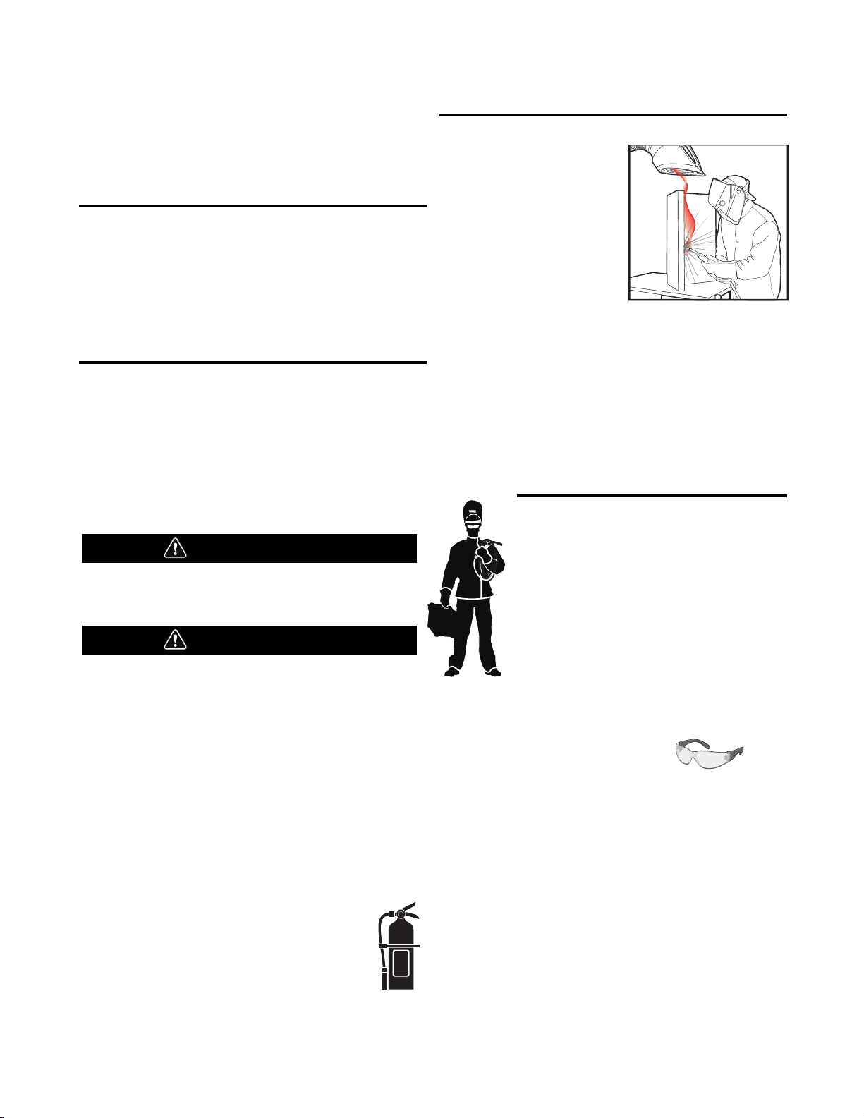
KEEP YOUR HEAD OUT OF THE FUMES.
DON’T get too close to the arc.
Use corrective lenses if necessary
to stay a reasonable distance
away from the arc.
READ and obey the Safety Data
Sheet (SDS) and the warning label
that appears on all containers of
welding materials.
USE ENOUGH VENTILATION or
exhaust at the arc, or both, to
keep the fumes and gases from
your breathing zone and the general area.
IN A LARGE ROOM OR OUTDOORS, natural ventilation may be
adequate if you keep your head out of the fumes (See below).
USE NATURAL DRAFTS or fans to keep the fumes away
from your face.
If you de velop unusual symptoms, see your supervisor.
Perhaps the welding atmosphere and ventilation system
should be checked.
WEAR CORRECT EYE, EAR &
BODY PROTECTION
PROTECT your eyes and face with welding helmet
properly fitted and with proper grade of filter plate
(See ANSI Z49.1).
PROTECT your body from welding spatter and arc
flash with protective clothing including woolen
clothing, flame-proof apron and gloves, leather
leggings, and high boots.
PROTECT others from splatter, flash, and glare
with protective screens or barriers.
IN SOME AREAS, protection from noise may be appropriate.
BE SURE protective equipment is in good condition.
Also, wear safety glasses in work area
AT ALL TIMES.
SPECIAL SITUATIONS
DO NOT WELD OR CUT containers or materials which previously
had been in contact with hazardous substances unless they are
properly cleaned. This is extremely dangerous.
DO NOT WELD OR CUT painted or plated parts unless special
precautions with ventilation have been taken. They can release
highly toxic fumes or gases.
Additional precautionary measures
PROTECT compressed gas cylinders from excessive heat,
mechanical shocks, and arcs; fasten cylinders so they cannot fall.
BE SURE cylinders are never grounded or part of an
electrical circuit.
REMOVE all potential fire hazards from welding area.
ALWAYS HAVE FIRE FIGHTING EQUIPMENT READY FOR
IMMEDIATE USE AND KNOW HOW TO USE IT.
WARNING
CAUTION
Safety 01 of 04 - 5/16/2018
Page 3
SECTION A:
WARNINGS
CALIFORNIA PROPOSITION 65 WARNINGS
WARNING: Breathing diesel engine exhaust
exposes you to chemicals known to the State
of California to cause cancer and birth defects,
or other reproductive harm.
• Always start and operate the engine in a
well-ventilated area.
• If in an exposed area, vent the exhaust to the outside.
• Do not modify or tamper with the exhaust system.
• Do not idle the engine except as necessary.
For more information go to
www.P65 warnings.ca.gov/diesel
WARNING: This product, when used for welding or
cutting, produces fumes or gases which contain
chemicals known to the State of California to cause
birth defects and, in some cases, cancer. (California
Health & Safety Code § 25249.5 et seq.)
WARNING: Cancer and Reproductive Harm
www.P65warnings.ca.gov
ARC WELDING CAN BE HAZARDOUS. PROTECT
YOURSELF AND OTHERS FROM POSSIBLE SERIOUS
INJURY OR DEATH. KEEP CHILDREN AWAY.
PACEMAKER WEARERS SHOULD CONSULT WITH
THEIR DOCTOR BEFORE OPERATING.
Read and understand the following safety highlights. For
additional safety information, it is strongly recommended
that you purchase a copy of “Safety in Welding & Cutting ANSI Standard Z49.1” from the American Welding Society,
P.O. Box 351040, Miami, Florida 33135 or CSA Standard
W117.2-1974. A Free copy of “Arc Welding Safety” booklet
E205 is available from the Lincoln Electric Company,
22801 St. Clair Avenue, Cleveland, Ohio 44117-1199.
BE SURE THAT ALL INSTALLATION, OPERATION,
MAINTENANCE AND REPAIR PROCEDURES ARE
PERFORMED ONLY BY QUALIFIED INDIVIDUALS.
FOR ENGINE POWERED
EQUIPMENT.
1.a. Turn the engine off before troubleshooting
and maintenance work unless the
maintenance work requires it to be running.
1.b. Operate engines in open, well-ventilated areas or vent the engine
exhaust fumes outdoors.
1.c. Do not add the fuel near an open flame welding
arc or when the engine is running. Stop the
engine and allow it to cool before refueling to
prevent spilled fuel from vaporizing on contact
with hot engine parts and igniting. Do not spill fuel when filling
tank. If fuel is spilled, wipe it up and do not start engine until
fumes have been eliminated.
1.d. Keep all equipment safety guards, covers
and devices in position and in good repair.
Keep hands, hair, clothing and tools away
from V-belts, gears, fans and all other
moving parts when starting, operating or
repairing equipment.
1.e. In some cases it may be necessary to remove safety guards to
perform required maintenance. Remove guards only when
necessary and replace them when the maintenance requiring
their removal is complete. Always use the greatest care when
working near moving parts.
1.f. Do not put your hands near the engine fan. Do not attempt to
override the governor or idler by pushing on the throttle control
rods while the engine is running.
1.g. To prevent accidentally starting gasoline engines while turning
the engine or welding generator during maintenance work,
disconnect the spark plug wires, distributor cap or magneto wire
as appropriate.
1.h. To avoid scalding, do not remove the radiator
pressure cap when the engine is
hot.
ELECTRIC AND
MAGNETIC FIELDS MAY
BE DANGEROUS
2.a. Electric current flowing through any conductor
causes localized Electric and Magnetic Fields (EMF).
Welding current creates EMF fields around welding cables
and welding machines
2.b. EMF fields may interfere with some pacemakers, and
welders having a pacemaker should consult their physician
before welding.
2.c. Exposure to EMF fields in welding may have other health effects
which are now not known.
2.d. All welders should use the following procedures in order to
minimize exposure to EMF fields from the welding circuit:
2.d.1. Route the electrode and work cables together - Secure
them with tape when possible.
2.d.2. Never coil the electrode lead around your body.
2.d.3. Do not place your body between the electrode and work
cables. If the electrode cable is on your right side, the
work cable should also be on your right side.
2.d.4. Connect the work cable to the workpiece as close as possible to the area being welded.
2.d.5. Do not work next to welding power source.
SAFETY
Safety 02 of 04 - 5/16/2018
Page 4
ELECTRIC SHOCK
CAN KILL.
3.a. The electrode and work (or ground) circuits are
electrically “hot” when the welder is on. Do
not touch these “hot” parts with your bare skin or wet clothing.
Wear dry, hole-free gloves to insulate hands.
3.b. Insulate yourself from work and ground using dry insulation.
Make certain the insulation is large enough to cover your full area
of physical contact with work and ground.
In addition to the normal safety precautions, if
welding must be performed under electrically
hazardous conditions (in damp locations or while
wearing wet clothing; on metal structures such as
floors, gratings or scaffolds; when in cramped
positions such as sitting, kneeling or lying, if there
is a high risk of unavoidable or accidental contact
with the workpiece or ground) use the following
equipment:
• Semiautomatic DC Constant Voltage (Wire) Welder.
• DC Manual (Stick) Welder.
• AC Welder with Reduced Voltage Control.
3.c. In semiautomatic or automatic wire welding, the electrode,
electrode reel, welding head, nozzle or semiautomatic welding
gun are also electrically “hot”.
3.d. Always be sure the work cable makes a good electrical
connection with the metal being welded. The connection should
be as close as possible to the area being welded.
3.e. Ground the work or metal to be welded to a good electrical (earth)
ground.
3.f. Maintain the electrode holder, work clamp, welding cable and
welding machine in good, safe operating condition. Replace
damaged insulation.
3.g. Never dip the electrode in water for cooling.
3.h. Never simultaneously touch electrically “hot” parts of electrode
holders connected to two welders because voltage
between the
two can be the total of the open circuit voltage of both
welders.
3.i. When working above floor level, use a safety belt to protect
yourself from a fall should you get a shock.
3.j. Also see It ems 6.c. and 8.
ARC RAYS CAN BURN.
4.a. Use a shield with the proper filter and cover plates to protect your
eyes from sparks and the rays of the arc when welding or
observing open arc welding. Headshield and filter lens should
conform to ANSI Z87. I standards.
4.b. Use suitable clothing made from durable flame-resistant material
to protect your skin and that of your helpers from the arc rays.
4.c. Protect other nearby personnel with suitable, non-flammable
screening and/or warn them not to watch the arc nor expose
themselves to the arc rays or to hot spatter or metal.
FUMES AND GASES
CAN BE DANGEROUS.
5.a. Welding may produce fumes and gases
hazardous to health. Avoid breathing these
fumes and gases. When welding, keep your head out of the fume.
Use enough ventilation and/or exhaust at the arc to keep fumes
and gases away from the breathing zone. When welding
hardfacing (see instructions on container or SDS)
or on lead or cadmium plated steel and other
metals or coatings which produce highly toxic
fumes, keep exposure as low as possible and
within applicable OSHA PEL and ACGIH TLV limits
using local exhaust or mechanical ventilation
unless exposure assessments indicate otherwise.
In confined spaces or in some circumstances,
outdoors, a respirator may also be required.
Additional precautions are also required when
welding
on galvanized steel.
5. b. The operation of welding fume control equipment is affected by
various factors including proper use and positioning of the
equipment, maintenance of the equipment and the specific
welding procedure and application involved. Worker exposure
level should be checked upon installation and periodically
thereafter to be certain it is within applicable OSHA PEL and
ACGIH TLV limits.
5.c. Do not weld in locations near chlorinated hydrocarbon vapors
coming from degreasing, cleaning or spraying operations. The
heat and rays of the arc can react with solvent vapors to form
phosgene, a highly toxic gas, and other irritating products.
5.d. Shielding gases used for arc welding can displace air and
cause
injury or death. Always use enough ventilation, especially in
confined areas, to insure breathing air is safe.
5.e. Read and understand the manufacturer’s instructions for this
equipment and the consumables to be used, including the
Safety Data Sheet (SDS) and follow your employer’s safety
practices. SDS forms are available from your welding
distributor or from the manufacturer.
5.f. Also see item 1.b.
SAFETY
Safety 03 of 04 - 5/16/2018
Page 5
WELDING AND CUTTING
SPARKS CAN CAUSE
FIRE OR EXPLOSION.
6.a. Remove fire hazards from the welding area. If
this is not possible, cover them to prevent the welding sparks
from starting a fire. Remember that welding sparks and hot
materials from welding can easily go through small cracks and
openings to adjacent areas. Avoid welding near hydraulic lines.
Have a fire extinguisher readily available.
6.b. Where compressed gases are to be used at the job site, special
precautions should be used to prevent hazardous situations.
Refer to “Safety in Welding and Cutting” (ANSI Standard Z49.1)
and the operating information for the equipment being used.
6.c. When not welding, make certain no part of the electrode circuit is
touching the work or ground. Accidental contact can cause
overheating and create a fire hazard.
6.d. Do not heat, cut or weld tanks, drums or containers until the
proper steps have been taken to insure that such procedures
will not cause flammable or toxic vapors from substances inside.
They can cause an explosion even though they have been
“cleaned”. For information, purchase “Recommended Safe
Practices for the Preparation for Welding and Cutting of
Containers and Piping That Have Held Hazardous Substances”,
AWS F4.1 from the American Welding Society
(see address above).
6.e. Vent hollow castings or containers before heating, cutting or
welding. They may explode.
6.f. Sparks and spatter are thrown from the welding arc. Wear oil free
protective garments such as leather gloves, heavy shirt, cuffless
trousers, high shoes and a cap over your hair. Wear ear plugs
when welding out of position or in confined places. Always wear
safety glasses with side shields when in a welding area.
6.g. Connect the work cable to the work as close to the welding area
as practical. Work cables connected to the building framework or
other locations away from the welding area increase the
possibility of the welding current passing through lifting chains,
crane cables or other alternate circuits. This can create fire
hazards or overheat lifting chains or cables until they fail.
6.h. Also see item 1.c.
6.I. Read and follow NFPA 51B “Standard for Fire Prevention During
Welding, Cutting and Other Hot Work”, available from NFPA, 1
Batterymarch Park, PO box 9101, Quincy, MA 022690-9101.
6.j. Do not use a welding power source for pipe thawing.
CYLINDER MAY EXPLODE IF
DAMAGED.
7.a. Use only compressed gas cylinders containing
the correct shielding gas for the process used
and properly operating regulators designed for
the gas and pressure used. All hoses, fittings,
etc. should be suitable for the application and
maintained in good condition.
7.b. Always keep cylinders in an upright position securely chained to
an undercarriage or fixed support.
7.c. Cylinders should be located:
• Away from areas where they may be struck or subjected
to physical damage.
• A safe distance from arc welding or cutting operations
and any other source of heat, sparks, or flame.
7.d. Never allow the electrode, electrode holder or any other
electrically “hot” parts to touch a cylinder.
7.e. Keep your head and face away from the cylinder valve outlet
when opening the cylinder valve.
7.f. Valve protection caps should always be in place and hand tight
except when the cylinder is in use or connected for use.
7.g. Read and follow the instructions on compressed gas cylinders,
associated equipment, and CGA publication P-l, “Precautions for
Safe Handling of Compressed Gases in Cylinders,” available from
the Compressed Gas Association, 14501 George Carter Way
Chantilly, VA 20151.
FOR ELECTRICALLY
POWERED EQUIPMENT.
8.a. Turn off input power using the disconnect
switch at the fuse box before working on
the equipment.
8.b. Install equipment in accordance with the U.S. National Electrical
Code, all local codes and the manufacturer’s recommendations.
8.c. Ground the equipment in accordance with the U.S. National
Electrical Code and the manufacturer’s recommendations.
Refer to
http://www.lincolnelectric.com/safety
for additional safety information.
SAFETY
Safety 04 of 04 - 5/16/2018
Page 6

CROSSLINC™ REMOTE
e
D
t
c
u
d
o
r
P
h
P
l
a
r
e
n
e
G
n
e
m
m
co
e
R
im
L
ss
ce
o
r
P
t
n
e
m
ip
u
q
E
n
e
m
m
co
e
R
a
e
F
n
sig
e
D
n
o
i
t
a
l
l
a
t
s
n
I
S
l
ica
n
ch
e
T
n
io
t
ca
o
L
u
q
e
r
F
h
ig
H
ld
e
W
W
A
M
S
ld
e
W
W
A
T
G
F
r
o
W
A
M
G
n
e
m
m
co
e
R
n
o
i
t
a
r
e
p
O
t
n
ro
F
se
Ca
t
n
ro
F
se
Ca
Se
Up
r-
we
o
P
n
e
M
Up
-
t
Se
c
s
ysica
e
d
a
it
im
L
e
d
r
u
t
e
p
.
cy
n
e
in
g
in
A
C
e
d
Co
Co
q
u
TABLE OF CONTENTS
E
G
A
P
n
o
i
t
p
i
r
3
.
.
.
.
.
.
.
.
.
.
.
.
.
.
.
.
.
.
.
.
.
.
.
.
.
.
.
.
.
.
.
.
.
.
.
.
.
.
.
.
.
.
.
.
.
.
.
.
.
.
.
.
.
.
.
.
.
.
.
.
.
.
.
.
.
.
.
.
.
.
.
.
.
.
.
.
.
.
.
.
.
.
.
.
.
.
.
.
.
.
.
.
.
.
.
.
.
.
.
.
.
.
.
.
.
.
.
.
.
.
.
.
.
.
.
.
.
.
.
.
.
.
.
.
.
.
.
.
.
.
.
.
.
.
.
.
.
n
io
t
ip
scr
e
D
l
3
.
.
.
.
.
.
.
.
.
.
.
.
.
.
.
.
.
.
.
.
.
.
.
.
.
.
.
.
.
.
.
.
.
.
.
.
.
.
.
.
.
.
.
.
.
.
.
.
.
.
.
.
.
.
.
.
.
.
.
.
.
.
.
.
.
.
.
.
.
.
.
.
.
.
.
.
.
.
.
.
.
.
.
.
.
.
.
.
.
.
.
.
.
.
.
.
.
.
.
.
.
.
.
.
.
.
.
.
.
.
.
.
.
.
.
.
.
.
.
.
.
.
.
.
.
.
.
.
.
.
.
.
.
.
.
.
.
.
.
.
.
s
sse
ce
o
r
P
d
3
.
.
.
.
.
.
.
.
.
.
.
.
.
.
.
.
.
.
.
.
.
.
.
.
.
.
.
.
.
.
.
.
.
.
.
.
.
.
.
.
.
.
.
.
.
.
.
.
.
.
.
.
.
.
.
.
.
.
.
.
.
.
.
.
.
.
.
.
.
.
.
.
.
.
.
.
.
.
.
.
.
.
.
.
.
.
.
.
.
.
.
.
.
.
.
.
.
.
.
.
.
.
.
.
.
.
.
.
.
.
.
.
.
.
.
.
.
.
.
.
.
.
.
.
.
.
.
.
.
.
.
.
.
.
.
.
.
.
.
.
.
.
.
.
.
.
.
.
.
.
.
s
n
io
t
3
.
.
.
.
.
.
.
.
.
.
.
.
.
.
.
.
.
.
.
.
.
.
.
.
.
.
.
.
.
.
.
.
.
.
.
.
.
.
.
.
.
.
.
.
.
.
.
.
.
.
.
.
.
.
.
.
.
.
.
.
.
.
.
.
.
.
.
.
.
.
.
.
.
.
.
.
.
.
.
.
.
.
.
.
.
.
.
.
.
.
.
.
.
.
.
.
.
.
.
.
.
.
.
.
.
.
.
.
.
.
.
.
.
.
.
.
.
.
.
.
.
.
.
.
.
.
.
.
.
.
.
.
.
.
.
.
.
.
.
.
.
.
.
.
.
.
.
s
n
io
t
a
it
3
.
.
.
.
.
.
.
.
.
.
.
.
.
.
.
.
.
.
.
.
.
.
.
.
.
.
.
.
.
.
.
.
.
.
.
.
.
.
.
.
.
.
.
.
.
.
.
.
.
.
.
.
.
.
.
.
.
.
.
.
.
.
.
.
.
.
.
.
.
.
.
.
.
.
.
.
.
.
.
.
.
.
.
.
.
.
.
.
.
.
.
.
.
.
.
.
.
.
.
.
.
.
.
.
.
.
.
.
.
.
.
.
.
.
.
.
.
.
.
.
.
.
.
.
.
.
.
.
.
.
.
.
.
.
s
ce
r
u
o
S
r
we
o
P
d
3
.
.
.
.
.
.
.
.
.
.
.
.
.
.
.
.
.
.
.
.
.
.
.
.
.
.
.
.
.
.
.
.
.
.
.
.
.
.
.
.
.
.
.
.
.
.
.
.
.
.
.
.
.
.
.
.
.
.
.
.
.
.
.
.
.
.
.
.
.
.
.
.
.
.
.
.
.
.
.
.
.
.
.
.
.
.
.
.
.
.
.
.
.
.
.
.
.
.
.
.
.
.
.
.
.
.
.
.
.
.
.
.
.
.
.
.
.
.
.
.
.
.
.
.
.
.
.
.
.
.
.
.
.
.
.
.
.
.
.
.
.
.
.
.
.
.
.
.
.
.
.
.
.
.
.
.
s
e
5
.
.
.
.
.
.
.
.
.
.
.
.
.
.
.
.
.
.
.
.
.
.
.
.
.
.
.
.
.
.
.
.
.
.
.
.
.
.
.
.
.
.
.
.
.
.
.
.
.
.
.
.
.
.
.
.
.
.
.
.
.
.
.
.
.
.
.
.
.
.
.
.
.
.
.
.
.
.
.
.
.
.
.
.
.
.
.
.
.
.
.
.
.
.
.
.
.
.
.
.
.
.
.
.
.
.
.
.
.
.
.
.
.
.
.
.
.
.
.
.
.
.
.
.
.
.
.
.
.
.
.
.
.
.
.
.
.
.
.
.
.
.
.
.
s
n
io
t
ica
cif
5
.
.
.
.
.
.
.
.
.
.
.
.
.
.
.
.
.
.
.
.
.
.
.
.
.
.
.
.
.
.
.
.
.
.
.
.
.
.
.
.
.
.
.
.
.
.
.
.
.
.
.
.
.
.
.
.
.
.
.
.
.
.
.
.
.
.
.
.
.
.
.
.
.
.
.
.
.
.
.
.
.
.
.
.
.
.
.
.
.
.
.
.
.
.
.
.
.
.
.
.
.
.
.
.
.
.
.
.
.
.
.
.
.
.
.
.
.
.
.
.
.
.
.
.
.
.
.
.
.
.
.
.
.
.
.
.
.
.
.
.
.
.
.
.
.
.
.
.
.
.
.
.
.
.
.
.
.
.
.
5
.
.
.
.
.
.
.
.
.
.
.
.
.
.
.
.
.
.
.
.
.
.
.
.
.
.
.
.
.
.
.
.
.
.
.
.
.
.
.
.
.
.
.
.
.
.
.
.
.
.
.
.
.
.
.
.
.
.
.
.
.
.
.
.
.
.
.
.
.
.
.
.
.
.
.
.
.
.
.
.
.
.
.
.
.
.
.
.
.
.
.
.
.
.
.
.
.
.
.
.
.
.
.
.
.
.
.
.
.
.
.
.
.
.
.
.
.
.
.
.
.
.
.
.
.
.
.
.
.
.
.
.
.
.
.
.
.
.
.
.
n
io
ct
e
t
o
r
P
6
.
.
.
.
.
.
.
.
.
.
.
.
.
.
.
.
.
.
.
.
.
.
.
.
.
.
.
.
.
.
.
.
.
.
.
.
.
.
.
.
.
.
.
.
.
.
.
.
.
.
.
.
.
.
.
.
.
.
.
.
.
.
.
.
.
.
.
.
.
.
.
.
.
.
.
.
.
.
.
.
.
.
.
.
.
.
.
.
.
.
.
.
.
.
.
.
.
.
.
.
.
.
.
.
.
.
.
.
.
.
.
.
.
.
.
.
.
.
.
.
.
.
.
.
.
.
.
.
.
.
.
.
.
.
.
.
.
.
.
.
.
.
.
.
.
.
.
.
p
u
t
e
S
g
7
.
.
.
.
.
.
.
.
.
.
.
.
.
.
.
.
.
.
.
.
.
.
.
.
.
.
.
.
.
.
.
.
.
.
.
.
.
.
.
.
.
.
.
.
.
.
.
.
.
.
.
.
.
.
.
.
.
.
.
.
.
.
.
.
.
.
.
.
.
.
.
.
.
.
.
.
.
.
.
.
.
.
.
.
.
.
.
.
.
.
.
.
.
.
.
.
.
.
.
.
.
.
.
.
.
.
.
.
.
.
.
.
.
.
.
.
.
.
.
.
.
.
.
.
.
.
.
.
.
.
.
.
.
.
.
.
.
.
.
.
.
.
.
.
.
.
.
.
p
u
t
e
S
8
.
.
.
.
.
.
.
.
.
.
.
.
.
.
.
.
.
.
.
.
.
.
.
.
.
.
.
.
.
.
.
.
.
.
.
.
.
.
.
.
.
.
.
.
.
.
.
.
.
.
.
.
.
.
.
.
.
.
.
.
.
.
.
.
.
.
.
.
.
.
.
.
.
.
.
.
.
.
.
.
.
.
.
.
.
.
.
.
.
.
.
.
.
.
.
.
.
.
.
.
.
.
.
.
.
.
.
.
.
.
.
.
.
.
.
.
.
.
.
.
.
.
.
.
.
.
.
.
.
.
.
.
.
p
u
t
e
S
g
in
ld
e
W
W
9
.
.
.
.
.
.
.
.
.
.
.
.
.
.
.
.
.
.
.
.
.
.
.
.
.
.
.
.
.
.
.
.
.
.
.
.
.
.
.
.
.
.
.
.
.
.
.
.
.
.
.
.
.
.
.
.
.
.
.
.
.
.
.
.
.
.
.
.
.
.
.
.
.
.
.
.
.
.
.
.
.
.
.
g
in
ld
e
W
c
r
A
r
o
F
s
e
iz
S
le
b
a
C
k
r
o
W
d
n
a
e
d
o
r
ct
le
E
d
10
.
.
.
.
.
.
.
.
.
.
.
.
.
.
.
.
.
.
.
.
.
.
.
.
.
.
.
.
.
.
.
.
.
.
.
.
.
.
.
.
.
.
.
.
.
.
.
.
.
.
.
.
.
.
.
.
.
.
.
.
.
.
.
.
.
.
.
.
.
.
.
.
.
.
.
.
.
.
.
.
.
.
.
.
.
.
.
.
.
.
.
.
.
.
.
.
.
.
.
.
.
.
.
.
.
.
.
.
.
.
.
.
.
.
.
.
.
.
.
.
.
.
.
.
.
.
.
.
.
.
.
.
.
.
.
.
.
.
.
.
.
.
.
.
.
.
.
.
.
ls
ro
t
n
11
.
.
.
.
.
.
.
.
.
.
.
.
.
.
.
.
.
.
.
.
.
.
.
.
.
.
.
.
.
.
.
.
.
.
.
.
.
.
.
.
.
.
.
.
.
.
.
.
.
.
.
.
.
.
.
.
.
.
.
.
.
.
.
.
.
.
.
.
.
.
.
.
.
.
.
.
.
.
.
.
.
.
.
.
.
.
.
.
.
.
.
.
.
.
.
.
.
.
.
.
.
.
.
.
.
.
.
.
.
.
.
.
.
.
.
.
.
.
.
.
.
.
.
.
.
.
.
.
.
.
s
n
io
t
scrip
De
l
ro
t
n
12
.
.
.
.
.
.
.
.
.
.
.
.
.
.
.
.
.
.
.
.
.
.
.
.
.
.
.
.
.
.
.
.
.
.
.
.
.
.
.
.
.
.
.
.
.
.
.
.
.
.
.
.
.
.
.
.
.
.
.
.
.
.
.
.
.
.
.
.
.
.
.
.
.
.
.
.
.
.
.
.
.
.
.
.
.
.
.
.
.
.
.
.
.
.
.
.
.
.
.
.
.
.
.
.
.
.
.
.
.
.
.
.
.
.
.
.
.
.
.
.
.
.
.
.
.
.
.
.
.
.
.
.
.
.
.
.
.
.
.
.
.
.
.
.
.
.
.
ce
n
e
u
12
.
.
.
.
.
.
.
.
.
.
.
.
.
.
.
.
.
.
.
.
.
.
.
.
.
.
.
.
.
.
.
.
.
.
.
.
.
.
.
.
.
.
.
.
.
.
.
.
.
.
.
.
.
.
.
.
.
.
.
.
.
.
.
.
.
.
.
.
.
.
.
.
.
.
.
.
.
.
.
.
.
.
.
.
.
.
.
.
.
.
.
.
.
.
.
.
.
.
.
.
.
.
.
.
.
.
.
.
.
.
.
.
.
.
.
.
.
.
.
.
.
.
.
.
.
.
.
.
.
.
.
.
.
.
.
.
.
.
.
.
.
.
.
.
.
.
.
.
.
.
.
.
.
.
.
.
.
.
e
c
Ac
nte
i
Ma
in
t
u
Ro
rio
e
P
lib
Ca
Troubl
PARTS
CONT
P
O
T
s
s
e
ic
d
ra
E
ART
na
t
e
NT
ori
io
s
M
M
L
S.
s
e
nc
in
a
in
a
Sp
n
hooti
IST .
DE
/
INCOL
L
15
.
.
.
.
.
.
.
.
.
.
.
.
.
.
.
.
.
.
.
.
.
.
.
.
.
.
.
.
.
.
.
.
.
.
.
.
.
.
.
.
.
.
.
.
.
.
.
.
.
.
.
.
.
.
.
.
.
.
.
.
.
.
.
.
.
.
.
.
.
.
.
.
.
.
.
.
.
.
.
.
.
.
.
.
.
.
.
.
.
.
.
.
.
.
.
.
.
.
.
.
.
.
.
.
.
.
.
.
.
.
.
.
.
.
.
.
.
.
.
.
.
.
.
.
.
.
.
.
.
.
.
.
.
.
.
.
.
.
.
.
.
.
.
.
.
.
.
.
.
.
.
.
.
.
.
.
.
.
e
16
.
.
.
.
.
.
.
.
.
.
.
.
.
.
.
.
.
.
.
.
.
.
.
.
.
.
.
.
.
.
.
.
.
.
.
.
.
.
.
.
.
.
.
.
.
.
.
.
.
.
.
.
.
.
.
.
.
.
.
.
.
.
.
.
.
.
.
.
.
.
.
.
.
.
.
.
.
.
.
.
.
.
.
.
.
.
.
.
.
.
.
.
.
.
.
.
.
.
.
.
.
.
.
.
.
.
.
.
.
.
.
.
.
.
.
.
.
.
.
.
.
.
.
.
.
.
.
.
.
.
.
.
.
.
.
.
.
.
.
.
.
.
.
.
.
.
ce
n
a
n
e
t
16
.
.
.
.
.
.
.
.
.
.
.
.
.
.
.
.
.
.
.
.
.
.
.
.
.
.
.
.
.
.
.
.
.
.
.
.
.
.
.
.
.
.
.
.
.
.
.
.
.
.
.
.
.
.
.
.
.
.
.
.
.
.
.
.
.
.
.
.
.
.
.
.
.
.
.
.
.
.
.
.
.
.
.
.
.
.
.
.
.
.
.
.
.
.
.
.
.
.
.
.
.
.
.
.
.
.
.
.
.
.
.
.
.
.
.
.
.
.
.
.
.
.
.
.
.
.
.
.
.
.
.
.
.
.
.
.
.
.
.
.
.
.
n
io
t
ica
cif
e
17
.
.
.
.
.
.
.
.
.
.
.
.
.
.
.
.
.
.
.
.
.
.
.
.
.
.
.
.
.
.
.
.
.
.
.
.
.
.
.
.
.
.
.
.
.
.
.
.
.
.
.
.
.
.
.
.
.
.
.
.
.
.
.
.
.
.
.
.
.
.
.
.
.
.
.
.
.
.
.
.
.
.
.
.
.
.
.
.
.
.
.
.
.
.
.
.
.
.
.
.
.
.
.
.
.
.
.
.
.
.
.
.
.
.
.
.
.
.
.
.
.
.
.
.
.
.
.
.
.
.
.
.
.
.
.
.
.
.
.
.
.
.
.
.
.
.
.
.
.
.
.
.
ng
COM
CTRIC.
E
L
E
N
COL
IN
L
PARTS.
.
.
.
.
.
.
.
.
.
.
.
.
.
.
.
.
.
.
.
.
.
.
.
.
.
.
.
.
.
.
.
.
.
.
.
.
.
.
.
.
.
.
.
.
.
.
.
.
.
.
.
.
.
.
.
.
.
.
.
.
.
.
.
.
.
.
.
.
.
.
.
.
.
.
.
.
.
.
.
.
.
.
.
.
.
.
.
.
.
.
.
.
.
.
.
.
.
.
.
.
.
.
.
.
.
.
.
.
.
.
GO
S,
ANUAL
M
ION
RUCT
INST
NT
CURRE
OST
M
OR
F
.
ICE
NOT
HOUT
WIT
D
E
DAT
UP
OR
D
CHANGE
BE
AY
M
S
AIL
T
.
COM
RIC.
CT
E
L
NE
2
Page 7

CROSSLINC™ REMOTE
ESCRIPTION
D
General Physical DescriPtion
The CrossLinc Remote is a portable unit which is connected at the
elding arc and allows the user to remotely control the welding
w
output without the use of control cables. The remote is small and
lightweight. It has LC-40HD style connections to the welding
cables for easy connection and disconnection. The CrossLinc
remote also has rubber corner caps and the controls themselves
re protected for extra durability. When the remote is connected
a
to any CrossLinc compatible power source
1)
(
, the output can be
adjusted in constant current or constant voltage modes.
General Functional DescriPtion
To use the CrossLinc Remote, connect the LC-40HD connectors to
the electrode cable and connect the work clip to the workpiece.
Once connected, the remote will power up immediately and
automatically pair with the power source. Once the remote is
paired, the power source preset can be adjusted with no
additional control cable. The display on the front of the remote
will show the preset value of current or voltage when not welding.
The remote will show actual voltage or current while welding, and
hold the last known current or voltage for 10 seconds after
welding is finished so that the user can verify his process settings.
recoMMenDeD Processes
• GTAW
• SMAW
• GMAW (with an across-the-arc wire feeder)
• FCAW-G (with an across-the-arc wire feeder)
• FCAW-S (with an across-the-arc wire feeder)
DesiGn Features
• CrossLinc Technology
- Allows for the adjustment of preset without cumbersome
ontrol cables
c
Allows the welder to get the right settings every time
-
without having to return to the power source
- No more control cables to carry, repair or trip over
• Digital display with 4 digits shows workpoint
• Encoder for full range workpoint adjustment
• LC-40HD connectors standard for easy setup
• Digital meters show actual voltage or current during welding
Process liMitations
Not compatible with high frequency GTAW
eQuiPMent liMitations
• The CrossLinc Remote can only be used with CrossLinc
compatible power sources
• CrossLinc can not change preset while welding
recoMMenDeD PoWer sources
• Flextec 350X
• Flextec 650X
(1) The CrossLinc Remote is not compatible with Flextec 350 Power Sources
with code numbers below 12600.
3
Page 8

CROSSLINC™ REMOTE
INSTALLATION
TECHNICAL SPECIFICATIONS -
K4345-1 - CrossLinc Remote
NSTALLATION
I
nput Voltage
I
Input Amperes
RATED OUTPUT
Duty Cycle Amperes
14-110 VDC
60% 550
100% 425
PHYSICAL DIMENSIONS
Model
Height
Width
Depth
Weight
Operating
Temperature
Storage
Temperature
TEMPERATURE RANGES
-40°F TO 104°F (-40°C TO 40°C)
-40°F TO 122°F (-40°C TO 50°C)
K4345-1
7.75”
10.0”
4.5”
10 LB
1
Thermal tests have been performed at ambient temperature. The duty
cycle (duty factor) at 40°C has been determined by simulation.
4
Page 9
CROSSLINC™ REMOTE
Read this entire installation section before you start
installation.
Safety Precautions
Do not attempt to use this equipment until you have
thoroughly read all installation, operating and maintenance
information supplied with your equipment. They include
important safety precautions and detailed operating and
maintenance instructions.
WARNING
ELECTRIC SHOCK can kill.
• Turn the input power OFF at the disconnect switch or
fuse box before attempting to connect or disconnect
input power lines, output cables or
control cables.
• Only qualified personnel should perform
this installation.
• Do not touch metal portions of the
CrossLinc Remote work clip when the welding power
source is on.
• Do not attach the work clip to the remote.
• Connect the work clip directly to the work, as close as
possible to the welding arc.
• Turn power off at the welding power source before
disconnecting the work clip from the work.
• Only use on power sources with open circuit voltages
less than 90 VDC.
NSTALLATION
I
select suitable location
Do not submerge the CrossLinc Remote.
The CrossLinc Remote is suitable for outdoor use.
hiGh FreQuency Protection
Locate the CrossLinc Remote away from radio controlled
machinery. The normal operation of the CrossLinc Remote may
adversely affect the operation of RF controlled equipment, which
may result in bodily injury or damage to the equipment.
5
Page 10
CROSSLINC™ REMOTE
sMaW WelDinG setuP
Flext
or
ec
Flext
NSTALLATION
I
IGURE A.1
F
AW
SM
:
x
0
5
3
x
0
5
6
ec
Mod
W
eld
e
T
Swit
erm
h
c
ON
:
)
t
en
res
p
if
(
h
c
Swit
al
in
Weld Cable (Work)
Weld Cable (Electrode)
Work Sense Lead
CrossLin
Remote
c
6
Page 11

CROSSLINC™ REMOTE
taW WelDinG setuP
G
Flext
or
ec
Flext
NSTALLATION
I
IGURE A.2
F
:
h
tc
i
w
S
e
od
M
en
h
w
e
c
r
ou
s
er
ow
p
e
th
on
e
od
m
W
A
GT
e
th
e
s
u
to
ed
d
en
m
om
ec
r
s
i
t
I
ow
l
a
n
i
t
l
u
es
r
l
l
i
w
d
an
e
od
m
t™
tar
S
h
c
ou
T
a
s
i
s
i
h
T
.
d
el
w
G
I
T
to
g
n
i
d
ten
n
i
t.
tar
s
G
I
T
t
en
r
r
u
c
g
n
ti
tar
s
e,
od
m
W
A
M
S
n
I
e.
od
m
W
A
M
S
e
th
n
i
d
el
w
G
I
T
to
e
l
b
i
s
os
p
o
s
al
s
i
t
I
y
l
al
c
ati
tom
au
ote
em
R
c
n
Li
s
os
r
C
e
h
T
.
g
n
ti
tar
s
h
atc
r
c
s
y
b
ated
ti
i
n
i
s
x
0
5
3
x
0
5
6
ec
i
to
ted
ec
n
on
c
en
h
w
g
n
i
d
el
w
G
I
T
for
s
g
n
etti
s
e
c
r
ou
s
er
ow
p
e
th
es
r
u
g
fi
on
c
e.
od
m
W
A
M
S
e
th
n
i
ty
i
ar
ol
p
e
v
ati
eg
n
e
od
tr
ec
el
N
O
:
t)
en
es
r
p
f
i
(
h
tc
i
w
S
al
n
i
m
er
T
d
el
W
Weld Cable
(Electrode, –)
Weld Cable
(Work, + )
Work Sense Lead
CrossLin
Remote
c
7
Page 12

CROSSLINC™ REMOTE
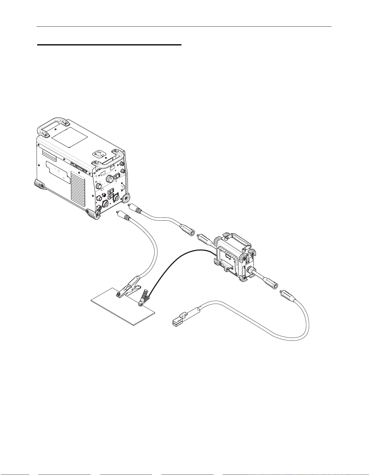
MaW or FcaW WelDinG setuP
G
The CrossLinc Remote can be connected in series with some
across-the-arc wire feeders to allow for remote output control
without a CrossLinc capable wire feeder. The compatible feeders
are listed below:
• LN-25
• LN-25 Pro Analog
• Activ8
• LN-15
FIGURE A.3
x
0
5
3
ec
Flext
650x
Flextec
or
NSTALLATION
I
Weld Cable (Work)
Weld Cable (Electrode)
Work Sense Lead
Magnum PRO
MIG Gun
CrossLin
Remote
c
LN-25
iv8
Act
PRO
or
8
Page 13

CROSSLINC™ REMOTE
recoMMenDeD electroDe anD WorK cable
iZes For arc WelDinG
s
abulated below are copper cable sizes recommended for
T
different currents and duty cycles. Lengths stipulated are the
distance from the welder to work and back to the welder again.
Cable sizes are increased for greater lengths primarily for the
purpose of minimizing cable drop.
RECOMMENDED CABLE SIZES (RUBBER COVERED COPPER - RATED 75°C)**
NSTALLATION
I
CABLE SIZES FOR COMBINED LENGTHS OF ELECTRODE AND WORK CABLES
0 TO 50 FT. 50 TO 100 FT. 100 TO 150 FT. 150 TO 200 FT. 200 TO 250 FT.
AMPERES
PERCENT DUTY
CYCLE
200 60 2 2 2 1 1/0
200 100 2 2 2 1 1/0
225 20 4 OR 5 3 2 1 1/0
225 40 & 30 3 3 2 1 1/0
250 30 3 3 2 1 1/0
250 40 2 2 1 1 1/0
250 60 1 1 1 1 1/0
250 100 1 1 1 1 1/0
300 60 1 1 1 1/0 2/0
325 100 2/0 2/0 2/0 2/0 3/0
350 60 1/0 1/0 2/0 2/0 3/0
400 60 2/0 2/0 2/0 3/0 4/0
400 100 3/0 3/0 3/0 3/0 4/0
500 60 2/0 2/0 3/0 3/0 4/0
** Tabled values are for operation at ambient temperatures of 40°C and
below. Applications above 40°C may require cables larger than recommended, or cables rated higher than 75°C
9
Page 14

CROSSLINC™ REMOTE
OPERATION
Read and understand this entire section before operating
your CrossLinc Remote.
Safety Precautions
Do not attempt to use this equipment until you have
thoroughly read all operating and maintenance manuals
supplied with your equipment and any related welding
achine it will be used with. They include important safety
m
precautions, operating and maintenance instructions and
parts lists.
WARNING
ELECTRIC SHOCK can kill.
• Do not touch electrically live parts such as
output terminals or internal wiring.
• Insulate yourself from the work and
ground.
• Always wear dry insulating gloves.
nly qualified personnel should operate this equipment.
O
PERATION
O
WELDING SPARKS can cause fire
or explosion.
• Keep flammable material away.
• Do not weld upon containers which have
held combustibles.
ARC RAYS can burn.
• Wear eye, ear and body protection.
FUMES AND GASES can
be dangerous.
Although the removal of the particulate
matter from welding smoke may reduce
the ventilation requirement, concentrations
of the clear exhausted fumes and gases
may still be hazardous to health. Avoid breathing concentrations of these fumes and gases. Use adequate
ventilation when welding. See ANSI Z49.1, "Safety in
Welding and Cutting", published by the American Welding
Society.
10
Page 15

CROSSLINC™ REMOTE
ase Front controls
c
Refer to Figure A.1:
1) Digital Display - The CrossLinc™ Remote has a digital
display that shows the preset. This display shows actual
amps or volts during welding. After welding, the digital
display will flash and display the last known voltage or
mperage.
a
2) Amperage LED - This LED indicates whether amps is being
displayed on the digital display.
3) Output Control Knob - This knob is used to adjust the preset
amps or volts depending on the mode selected at the power
source. The preset value will be displayed on the digital
display.
4) Volts LED - This LED indicates whether volts is being
displayed on the digital display.
5) CrossLinc™ Communication LED - The CrossLinc™
Communication LED displays whether the feeder is connected
to the power source. When the power feeder is searching for
a connection, or is connected to a power source that does not
support CrossLinc™, the LED will not illuminate. When the
feeder has successfully connected to the power source, the
LED will be illuminated.
PERATION
O
6) Setup Button (hidden) - The setup button is located to the
right of the digital display. It is accessed by using a paperclip
to press it through a pinhole in the nameplate. This button
enters the setup menu to change optional settings.
7) Input Cable (from Power Source) - The remote is equipped
ith a 4/0 input cable with an LC40HD male style connector.
w
Connect this cable to the power source output.
8) Output Cable (to Electrode) Output Cable - The remote is
equipped with a 4/0 output cable with an LC40HD female
style connector. Connect this cable to the electrode holder,
torch, or across-the-arc wire feeder.
9) Work Sense Lead - The Work Sense Lead is used to power
the remote and communicate with the power source.
Connecting the Work Sense Lead is critical for the operation
of the remote, as it will not power up if it is disconnected.
FIGURE B.1
11
Page 16

1
2
.
3
3
2
4
0
CROSSLINC™ REMOTE
PERATION
O
VerVieW oF oPeration
o
The CrossLinc Remote will power up when the work clip is
connected to the workpiece and the output studs of the welding
power source are ON. Once it is powered up, the remote will
establish a CrossLinc connection with the power source. When
he connection is established, the CrossLinc LED will light green
t
and workpoint will be displayed on the remote. Now the remote is
ready for use and the power source output can be adjusted using
the control knob.
An example of the display when ready for use is shown below:
FIGURE B.2
In this case the current is set for 240 amps.
If the remote displays a negative sign before the setpoint, it
indicates that the remote is connected for negative polarity.
Once a CrossLinc connection is established, the remote overrides
the Local setting of the power source, even if is set in “Local”
control mode. Then, when the remote is disconnected, the power
source will return to the local setting after 15 seconds.
If Arc Hours display is enabled (see setup menu for instructions on
how to enable), then the accumulated arc hours will be displayed
for 5 seconds after startup. The time will be in the format HH.MM
as shown in the example below. In the example, the accumulated
arc time is 12 hours and 33 minutes.
FIGURE B.3
arbon arc GouGinG
c
CrossLinc technology allows the user to switch between welding
and gouging easily, without returning to the power source. In
order to gouge, use the following setup instructions:
1. Set the Local/Remote output switch on the power source to
“Local”, with the CrossLinc Remote disconnected.
2. Adjust the output control knob on the power source to the
desired gouging output level. (Example: 700A)
3. Connect the CrossLinc Remote with stick electrode holder and
turn the weld terminals ON. At this point, the CrossLinc
Remote will take over output control.
4. Adjust the CrossLinc Remote to the desired welding output
level. (Example: 125A for 1/8” E7018 stick welding).
5. Continue to weld with the CrossLinc Remote connected,
adjusting the output on the remote as required.
6. When gouging is required, disconnect the CrossLinc Remote
and replace it with an arc gouging torch.
7. Once the CrossLinc Remote is disconnected, the power
source will return to the output setting from the output control
knob on the power source. In this example, 700A.
8. Gouge at 700A for as long as is desired.
9. When gouging is complete, reconnect the CrossLinc Remote,
and it will take over output control again.
NOTE: The same weld mode must be used for both gouging and
welding with this procedure. For example, if stick welding is
being done, gouging must be performed in SMAW mode.
FIGURE B.4
al
oc
L
:
ch
Swit
trol
Con
t
u
p
t
Ou
AW
SM
:
Switch
e
Mod
Amps
ng
Gougi
:
g
tin
Set
t
u
tp
Ou
Local
t
Presen
(If
Switch
als
ermin
T
Weld
Disconnect for
Gouging
ON
):
When the arc time reaches 99.59, it will roll over to 00.00 and
start counting again.
Electrode Holder
Arc Gouging Torch
12
Page 17

h
r
5
8
8
8
8
h
o
l
d
c
u
f
b
CROSSLINC™ REMOTE
PERATION
O
et-uP Menu
s
To enter the set-up menu:
To enter the set-up menu, use paper clip to press the small button
located below the Display on the case front.
FIGURE B.4
arc hours
The first option in the setup menu will be for Arc Hours. If this
option is turned “ON”, accumulated arc hours will be displayed on
power up. When in the setup option for Arc Hours the display will
show the following:
FIGURE B.5
etup Button
S
oltMeter/aMMeter holD tiMe
V
The CrossLinc Remote will display the actual amperage or voltage
after welding has stopped. The hold time option will hold these
values for either 10 seconds or 300 seconds. When in the setup
option for hold time, the display will show the following:
FIGURE B.6
To set the hold time to 10 seconds, turn the output control knob to
the left. To set the hold time to 300 seconds, turn the output
control knob to the right.
The factory default is 10 seconds.
cV FeeDbacK
When being used in a constant voltage mode, the CrossLinc
Remote can be set to display either actual voltage or actual
current during welding and during the hold time. When in the
setup menu for CV Feedback, the display will show the following:
FIGURE B.7
To enable Arc Hours display, turn the control knob to the right
while in this menu. To disable Arc Hours display, turn the control
knob left.
The factory default for Arc Hours is “OFF”.
The feedback type is indicated by which LED is lit, either “A” or
“V”. If the “A” LED is lit while in this menu, the CrossLinc Remote
will display actual current while welding in a CV mode. If the “V”
LED is lit, the CrossLinc Remote will display actual voltage while
welding in a CV mode.
To choose current, turn the output control knob to the left. To
choose voltage, turn the output control knob to the right.
The factory default is voltage.
13
Page 18

v
o
L
C
U
r
r
S
t
3
CROSSLINC™ REMOTE
PERATION
O
utoMatic tiG
a
The CrossLinc Remote can automatically optimize the power
source settings for scratch start TIG operation when it is
connected for electrode negative polarity and the power source is
in the SMAW mode. This must be disabled if stick welding with
egative polarity. When in the setup menu for Automatic TIG, the
n
display will show the following:
IGURE B.8
F
Turn the knob to the right to select “Auto” TIG.
Turn the knob to the left to select “off”. This setting must be
turned “off” to stick weld with negative polarity.
The factory default is “Auto”.
VoltaGe calibration
To calibrate the arc voltage display, before entering the setup
menu:
• Determine the ratio of the actual arc voltage and the arc
voltage displayed by the CrossLinc Remote.
While in the setup menu, adjust the calibration factor as follows:
Actual arc voltage / displayed arc voltage = calibration factor
(Example: 20.0 / 20.5 = 0.97)
The calibration factor is factory set as 1.00
When in the setup menu for voltage calibration the display will
show the following:
FIGURE B.9
urrent calibration
c
To calibrate the arc current display, before entering the setup
menu:
• Determine the ratio of the actual arc current and the arc
current displayed by the CrossLinc Remote.
While in the setup menu, adjust the calibration factor as follows:
Actual arc current / displayed arc current = calibration factor
(Example: 200 / 205 = 0.97)
The calibration factor is factory set as 1.00
When in the setup menu for current calibration the display will
show the following:
FIGURE B.10
Turn the knob to the right to increase the calibration factor, and to
the left to decrease the calibration factor.
The factory default is 1.00.
Factory reset
In order to reset your setup parameters to the factory default, hold
the setup button for 5 seconds while the remote is in an idle state.
While resetting, the displays will show the following. The last digit
is the seconds to reset. At the end of the countdown, the reset
will take place and the display will return to its idle state. If the
setup button is released before the countdown is complete, the
reset will not take place.
FIGURE B.11
Turn the knob to the right to increase the calibration factor, and to
the left to decrease the calibration factor.
The factory default is 1.00
14
Page 19

CROSSLINC™ REMOTE
OPTIONAL KITS AND
ACCESSORIES
CCESSORIES
A
Product Number
K2483-2
K2483-3
K2484-2
K2484-3
K2485-2
K2485-3
K2487-10
K3416-70
K3416-90
K3417-70
K3417-90
DESCRIPTION
2/0 WELD CABLE WITH LC40 MALE CONNECTOR AND BARE END - 10 FT
3/0 WELD CABLE WITH LC40HD MALE CONNECTOR AND BARE END - 10 FT
2/0 WELD CABLE WITH LC40 MALE CONNECTOR AND 0.53" LUG - 50 FT
3/0 WELD CABLE WITH LC40HD MALE CONNECTOR AND 0.53" LUG - 50 FT
2/0 WELD CABLE WITH LC40 MALE AND FEMALE CONNECTOR - 50 FT
3/0 WELD CABLE WITH LC40HD MALE AND FEMALE CONNECTOR - 50 FT
INSULATED ADAPTER FOR OUTPUT STUD TO FEMALE LC40HD
LC40 FEMALE CONNECTOR (1/0 THRU 2/0)
LC-40HD FEMALE CONNECTOR (3/0 THRU 4/0)
LC40 MALE CONNECTOR (1/0 THRU 2/0)
LC-40HDMALE CONNECTOR (3/0 THRU 4/0)
15
Page 20

CROSSLINC™ REMOTE
AINTENANCE
M
MAINTENANCE
WARNING
ELECTRIC SHOCK can kill.
• Turn the input power OFF at the welding
power source before installation or
changing drive rolls and/or guides.
• Do not touch electrically live parts.
• When inching with the gun trigger, electrode and drive
mechanism are "hot" to work and ground and could
remain energized several seconds after the gun trigger
is released.
• Do not operate with covers, panels or guards removed
or open.
• Only qualified personnel should perform maintenance
work.
routine Maintenance
Check weld cables.
Clean and tighten all welding cable connections.
PerioDic Maintenance
Blow out or vacuum the inside of the remote.
TROUBLESHOOTING
hoW to use troubleshootinG GuiDe
WARNING
Service and Repair should only be performed by Lincoln
Electric Factory Trained Personnel. Unauthorized repairs
performed on this equipment may result in danger to the
technician and machine operator and will invalidate your
factory warranty. For your safety and to avoid Electrical
Shock, please observe all safety notes and precautions
etailed throughout this manual.
d
This Troubleshooting Guide is provided to help you locate and
repair possible machine malfunctions. Simply follow the threestep procedure listed below.
Step 1. LOCATE PROBLEM (SYMPTOM).
Look under the column labeled “PROBLEM (SYMPTOMS).” This
column describes possible symptoms that the machine may
exhibit. Find the listing that best describes the symptom that the
machine is exhibiting.
Step 2. POSSIBLE CAUSE.
The second column labeled “POSSIBLE CAUSE” lists the obvious
external possibilities that may contribute to the machine symptom.
Step 3. RECOMMENDED COURSE OF ACTION
This column provides a course of action for the Possible Cause,
generally it states to contact you local Lincoln Authorized Field
Service Facility.
If you do not understand or are unable to perform the
Recommended Course of Action safely, contact your local
Lincoln Authorized Field Service Facility.
E
WARNING
ELECTRIC SHOCK can kill.
• Turn off machine at the disconnect switch
on the rear of the machine and remove
main power supply connections before
doing any troubleshooting.
16
Page 21

ROSSLINC REMOTE
C
TROUBLESHOOTING
Observe all Safety Guidelines detailed throughout this manual
PROBLEM
(SYMPTOMS)
The remote does power up.
No LEDs or displays are lit.
The display shows “---“
constantly at idle. The
green CrossLinc light is not
lit.
POSSIBLE AREAS OF
MISADJUSTMENT(S)
1. The work sense lead is disconnected or
is a poor electrical connection. (Across
the arc models)
. The power source output is OFF.
2
1. The remote is not connected to a
CrossLinc compatible power source.
2. Voltage feedback is not working in the
remote.
3. Current feedback is not working in the
power source.
4. No current pulses are present in work
sense lead at idle.
RECOMMENDED COURSE OF ACTION
1. Connect the work sense lead to the work in a
location free of dirt, rust and paint.
. Turn ON the power source output.
2
1. Connect to a CrossLinc compatible power source.
Compatible power sources must have an “X” at the
end of the name. (i.e. Flextec 350X)
2. Strike an arc and determine that the displayed
voltage on the remote matches the actual arc
voltage. If it does not, verify lead connections in
the remote. If all lead connections are good,
replace User Interface PC Board.
3. Strike an arc and verify that the current displayed
on the power source matches the actual arc
current. If it does not match, inspect current
transducer in power source, and replace if faulty.
4. Verify that the OCV is 65V or less. If it is, replace
User Interface PC Board.
The CrossLinc LED is
Orange and the remote is
not communicating with a
power source
1. The remote is overheated. 1. Move to a cooler location
If for any reason you do not understand the test procedures or are unable to perform the tests/repairs safely, contact your
Lincoln Authorized Service Facility for technical troubleshooting assistance before you proceed.
WWW.LINCOLNELECTRIC.COM/LOCATOR
17
Page 22

CROSSLINC™ REMOTE
CLEVELAND, OHIO U.S.A .
R
R - RED
B - BLACK
U - BLUE
LEAD COLOR CODING
ELECTRICAL SYMBOLS PER E1537.
W - WHITE
GENERAL INFORMATION
INPUT ELECTRODE
CABLE CONNECTION
Y -YELLOW
J11
CAVITY NUMBERING SEQUENCE
(VIEWED FROM COMPONENT SIDE OF P.C. BOARD)
J31
9
8
16
1
4
6
1
3
J32, J42
J41
3
4
1
2
J33, J34
5
4
8
1
M26034PRINT
A.03
UI / DISPLAY
P.C. BOARD
123456789
10111213141516
J31
12345
6
J42
1234567
8
J33
(VIEWED FROM
INSIDE FEEDER)
859
8510
857
333
334
338
336
332
67
332
333
WORK A
336
338
123
4
J41
J34
J32
123456
334
801
802
806804
PANEL ENCODER
WFS/AMPS
857
859
8510
802
804
801
806
CURRENT
TRANSDUCER
(LEM)
POWER SUPPLY
P.C. BOARD
1234567
8
(VIEWED FROM
INSIDE FEEDER)
67A
67
67A
J11
TO TORCH
TO WORK CLIP
WORK C
WORK B
WORK B
WORK A
337
J50
337
CROSSLINC REMOTE WIRING DIAGRAM
IAGRAMS
D
18
Page 23

Page 24

Page 25

CrossLinc Remote -
12605
Page 26

General Assembly
KEY PART NUMBER DESCRIPTION QTY
1 9SG8711 BASE 1
2 9SS32149 ANGLED PCB BRACKET 1
3A 9SM25777 CORNER CAP 8
3B 9SS9225-100 SELF TAPPING SCREW 8
3C 9SS9262-182 PLAIN WASHER 8
4A 9SS18170 HANDLE ASBLY 1
9SS9262-113 PLAIN WASHER 2
9SS9262-98 PLAIN WASHER 2
9SCF000170 1/4-20X.375HHB 2
5A 9SG8696-1 POWER SUPPLY PC BD 1
5B 9SS9225-76 SELF TAPPING SCREW 2
9SM26153 WELD CABLE ASSEMBLY 1
9SS32142 LEAD COVER PLATE 2
6B 9SS19999-4 CORD GRIP CONNECTOR 2
9SS31643-3 NYLON LOCKNUT 1" NPT 2
6D 9SS18504-6 CURRENT TRANSDUCER 1
6E 9SM26151 iNSULATION PIERCING CONNECTOR 1
6F K3416-90 TWECO STYLE PLUG FOR 3/0-4/0 CABLE 1
6G K3417-90 TWECO STYLE RECEPTACLE FOR 3/0-4/0 CABLE 1
9SS9225-100 SELF TAPPING SCREW 4
9SL17127 HARNESS 1
8A 9ST9274-1 GROMMET 1
9SS32141 GROUND LEAD CONNECTER PLATE 1
9SS9225-100 SELF TAPPING SCREW 4
9SS17211-7 GROUND LEAD ASBLY 1
9SM22861 WORK CLAMP LIGHT DUTY 1
10 9SG8710 ROOF 1
11 9SG6529 UI TRIM 1
9SG8748 USER INTERFACE ASBLY 1
12A 9SL17048 UI CASE FRONT 1
12B 9SG8747 NAMEPLATE 1
12C 9SG8651-1 UI PC BD 1
12D 9ST10082-12 SEMS SCREW 4
12E 9SM17789-6 ENCODER 1
Printed 11/04/2016 at 07:12:15. Produced by Enigma.
CrossLinc Remote - 12605 3
Page 27

General Assembly
KEY PART NUMBER DESCRIPTION QTY
12F 9ST7028-241 INSULATION TUBE 1
12G 9ST14034 SEAL 1
12H 9SM22778-2 KNOB 1.5" 1
12J 9SM25778 KNOB GUARD 1
12K 9SS9225-99 SELF TAPPING SCREW 2
12L 9SS9225-99 SELF TAPPING SCREW 4
13 9SS20601-5 WARNING DECAL 1
14 9SM26268 DECAL 1
15 9SM26268 DECAL 1
16 9SM26268 DECAL 1
17 9SM26268 DECAL 1
18 9SM26268 DECAL 1
4 CrossLinc Remote - 12605
Printed 11/04/2016 at 07:12:15. Produced by Enigma.
Page 28

General Assembly
P-1081-C.jpg
Printed 11/04/2016 at 07:12:15. Produced by Enigma.
CrossLinc Remote - 12605 5
Page 29

WARNING
panish
S
AVISO DE
PRECAUCION
French
ATTENTION
erman
G
WARNUNG
ortuguese
P
ATENÇÃO
Japanese
Chinese
l Do not touch electrically live parts or
electrode with skin or wet clothing.
l Insulate yourself from work and
ground.
l
No toque las partes o los electrodos
bajo carga con la piel o ropa mojada.
l Aislese del trabajo y de la tierra.
l Ne laissez ni la peau ni des vête-
ments mouillés entrer en contact
avec des pièces sous tension.
l
Isolez-vous du travail et de la terre.
l Berühren Sie keine stromführenden
Teile oder Elektroden mit Ihrem
Körper oder feuchter Kleidung!
l Isolieren Sie sich von den
Elektroden und dem Erdboden!
l Não toque partes elétricas e elec-
trodos com a pele ou roupa molhada.
l
Isole-se da peça e terra.
l Keep flammable materials away.
l
Mantenga el material combustible
fuera del área de trabajo.
l
Gardez à l’écart de tout matériel
inflammable.
l Entfernen Sie brennbarres Material!
l
Mantenha inflamáveis bem guardados.
l Wear eye, ear and body protection.
l
Protéjase los ojos, los oídos y el
cuerpo.
l
Protégez vos yeux, vos oreilles et
votre corps.
l Tragen Sie Augen-, Ohren- und Kör-
perschutz!
l
Use proteção para a vista, ouvido e
corpo.
Korean
Arabic
READ AND UNDERSTAND THE MANUFACTURER’S INSTRUCTION FOR THIS EQUIPMENT AND THE CONSUMABLES TO BE
USED AND FOLLOW YOUR EMPLOYER’S SAFETY PRACTICES.
SE RECOMIENDA LEER Y ENTENDER LAS INSTRUCCIONES DEL FABRICANTE PARA EL USO DE ESTE EQUIPO Y LOS
CONSUMIBLES QUE VA A UTILIZAR, SIGA LAS MEDIDAS DE SEGURIDAD DE SU SUPERVISOR.
LISEZ ET COMPRENEZ LES INSTRUCTIONS DU FABRICANT EN CE QUI REGARDE CET EQUIPMENT ET LES PRODUITS A
ETRE EMPLOYES ET SUIVEZ LES PROCEDURES DE SECURITE DE VOTRE EMPLOYEUR.
LESEN SIE UND BEFOLGEN SIE DIE BETRIEBSANLEITUNG DER ANLAGE UND DEN ELEKTRODENEINSATZ DES HERSTELLERS. DIE UNFALLVERHÜTUNGSVORSCHRIFTEN DES ARBEITGEBERS SIND EBENFALLS ZU BEACHTEN.
Page 30

l Keep your head out of fumes.
l Use ventilation or exhaust to
remove fumes from breathing zone.
l Turn power off before servicing.
l Do not operate with panel open or
guards off.
WARNING
l Los humos fuera de la zona de res-
piración.
l Mantenga la cabeza fuera de los
humos. Utilice ventilación o
aspiración para gases.
l Gardez la tête à l’écart des fumées.
l Utilisez un ventilateur ou un aspira-
teur pour ôter les fumées des zones
de travail.
l
Vermeiden Sie das Einatmen von
Schweibrauch!
l Sorgen Sie für gute Be- und
Entlüftung des Arbeitsplatzes!
l Mantenha seu rosto da fumaça.
l Use ventilação e exhaustão para
remover fumo da zona respiratória.
l Desconectar el cable de ali-
mentación de poder de la máquina
antes de iniciar cualquier servicio.
l Débranchez le courant avant l’entre-
tien.
l
Strom vor Wartungsarbeiten
abschalten! (Netzstrom völlig öffnen; Maschine anhalten!)
l Não opere com as tampas removidas.
l Desligue a corrente antes de fazer
serviço.
l
Não toque as partes elétricas nuas.
l No operar con panel abierto o
guardas quitadas.
l N’opérez pas avec les panneaux
ouverts ou avec les dispositifs de
protection enlevés.
l
Anlage nie ohne Schutzgehäuse
oder Innenschutzverkleidung in
Betrieb setzen!
l
Mantenha-se afastado das partes
moventes.
l Não opere com os paineis abertos
ou guardas removidas.
Spanish
AVISO DE
PRECAUCION
rench
F
ATTENTION
German
WARNUNG
ortuguese
P
ATENÇÃO
Japanese
Chinese
Korean
Arabic
LEIA E COMPREENDA AS INSTRUÇÕES DO FABRICANTE PARA ESTE EQUIPAMENTO E AS PARTES DE USO, E SIGA AS
PRÁTICAS DE SEGURANÇA DO EMPREGADOR.
Page 31

CUSTOMER ASSISTANCE POLICY
The business of The Lincoln Electric Company is manufacturing and
selling high quality welding equipment, consumables, and cutting
equipment. Our challenge is to meet the needs of our customers and
o exceed their expectations. On occasion, purchasers may ask
t
Lincoln Electric for advice or information about their use of our
products. We respond to our customers based on the best information
in our possession at that time. Lincoln Electric is not in a position to
warrant or guarantee such advice, and assumes no liability, with
respect to such information or advice. We expressly disclaim any
warranty of any kind, including any warranty of fitness for any
customer’s particular purpose, with respect to such information or
advice. As a matter of practical consideration, we also cannot assume
any responsibility for updating or correcting any such information or
advice once it has been given, nor does the provision of information
or advice create, expand or alter any warranty with respect to the sale
of our products.
Lincoln Electric is a responsive manufacturer, but the selection and
use of specific products sold by Lincoln Electric is solely within the
control of, and remains the sole responsibility of the customer. Many
variables beyond the control of Lincoln Electric affect the results
obtained in applying these types of fabrication methods and service
requirements.
Subject to Change – This information is accurate to the best of our
knowledge at the time of printing. Please refer to
www.lincolnelectric.com for any updated information.
 Loading...