

Page 1
Operator’s Manual
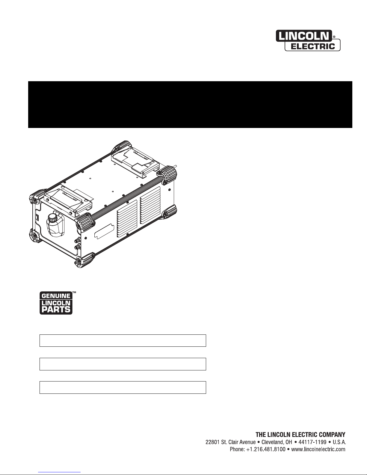
COOL ARC ® 55 & COOL ARC ® 55 ALUMINUM
WATER COOLER
For use with machines having Code Numbers:
11859, 12377
Register your machine:
www.lincolnelectric.com/register
Authorized Service and Distributor Locator:
www.lincolnelectric.com/locator
Save for future reference
Date Purchased
Code: (ex: 10859)
Serial: (ex: U1060512345)
IM10117-A | Issue D ate Mar-15
© Lincoln Global, Inc. All Rights Reserved.
Page 2
THANK YOU FOR SELECTING
A QUALITY PRODUCT BY
LINCOLN ELEC TRIC.
PLEASE EXAMINE CARTON AND EQUIPMENT FOR DAMAGE
IMMEDIATELY
When this equipment is shipped, title passes to the purchaser upon
receipt by the carrier. Consequently, Claims for material damaged in
shipment must be made by the purchaser against the transportation
company at the time the shipment is received.
SAFETY DEPENDS ON YOU
Lincoln arc welding and cutting equipment is designed and built with
safety in mind. However, your overall safety can be increased by
proper installation ... and thoughtful operation on your part.
DO NOT INSTALL, OPERATE OR REPAIR THIS EQUIPMENT
WITHOUT READING THIS MANUAL AND THE SAFETY PRECAUTIONS
CONTAINED THROUGHOUT. And, most importantly, think before you
act and be careful.
WARNING
This statement appears where the information must be followed
exactly to avoid serious personal injury or loss of life.
CAUTION
This statement appears where the information must be followed to
avoid minor personal injury or damage to this equipment.
KEEP YOUR HEAD OUT OF THE FUMES.
DON’T get too close to the arc. Use
corrective lenses if necessary to
stay a reasonable distance away
from the arc.
READ and obey the Material Safety
Data Sheet (MSDS) and the warning
label that appears on all containers
of welding materials.
USE ENOUGH VENTILATION or
exhaust at the arc, or both, to keep
the fumes and gases from your breathing zone and the general area.
IN A LARGE ROOM OR OUTDOORS, natural ventilation may be
adequate if you keep your head out of the fumes (See below).
USE NATURAL DRAFTS or fans to keep the fumes away from your
face.
If you de velop unusual symptoms, see your supervisor. Perhaps the
welding atmosphere and ventilation system should be checked.
WEAR CORRECT EYE, EAR & BODY PROTECTION
PROTECT your eyes and face with welding helmet
properly fitted and with proper grade of filter plate
(See ANSI Z49.1).
PROTECT your body from welding spatter and arc
flash with protective clothing including woolen
clothing, flame-proof apron and gloves, leather
leggings, and high boots.
PROTECT others from splatter, flash, and glare with
protective screens or barriers.
IN SOME AREAS, protection from noise may be
appropriate.
BE SURE protective equipment is in good condition.
Also, wear safety glasses in work area AT ALL
TIMES.
SPECIAL SITUATIONS
DO NOT WELD OR CUT containers or materials which previously had
been in contact with hazardous substances unless they are properly
cleaned. This is extremely dangerous.
DO NOT WELD OR CUT painted or plated parts unless special
precautions with ventilation have been taken. They can release highly
toxic fumes or gases.
Additional precautionary measures
PROTECT compressed gas cylinders from excessive heat, mechanical
shocks, and arcs; fasten cylinders so they cannot fall.
BE SURE cylinders are never grounded or part of an electrical circuit.
REMOVE all potential fire hazards from welding area.
ALWAYS HAVE FIRE FIGHTING EQUIPMENT READY FOR
IMMEDIATE USE AND KNOW HOW TO USE IT.
Page 3
SECTION A:
WARNINGS
CALIFORNIA PROPOSITION 65 WARNINGS
Diesel Engines
Diesel engine exhaust and some of its constituents are known
to the State of California to cause cancer, birth defects, and other
reproductive harm.
Gasoline Engines
The engine exhaust from this product contains chemicals known
to the State of California to cause cancer, birth defects, or other
reproductive harm.
ARC WELDING CAN BE HAZARDOUS. PROTECT YOURSELF AND
OTHERS FROM POSSIBLE SERIOUS INJURY OR DEATH. KEEP CHILDREN AWAY. PACEMAKER WEARERS SHOULD CONSULT WITH
THEIR DOCTOR BEFORE OPERATING.
Read and understand the following safety highlights. For additional
safety information, it is strongly recommended that you purchase a
copy of “Safety in Welding & Cutting - ANSI Standard Z49.1” from the
American Welding Society, P.O. Box 351040, Miami, Florida 33135 or
CSA Standard W117.2-1974. A Free copy of “Arc Welding Safety”
booklet E205 is available from the Lincoln Electric Company, 22801
St. Clair Avenue, Cleveland, Ohio 44117-1199.
BE SURE THAT ALL INSTALLATION, OPERATION,
MAINTENANCE AND REPAIR PROCEDURES ARE
PERFORMED ONLY BY QUALIFIED INDIVIDUALS.
AFETY
S
1.d. Keep all equipment safety guards, covers and
devices in position and in good repair.Keep
hands, hair, clothing and tools away from
-belts, gears, fans and all other moving parts
V
when starting, operating or repairing
equipment.
1.e. In some cases it may be necessary to remove safety guards to
perform required maintenance. Remove guards only when
necessary and replace them when the maintenance requiring
their removal is complete. Always use the greatest care when
working near moving parts.
1.f. Do not put your hands near the engine fan. Do not attempt to
verride the governor or idler by pushing on the throttle control
o
rods while the engine is running.
1.g. To prevent accidentally starting gasoline engines while turning
the engine or welding generator during maintenance work,
disconnect the spark plug wires, distributor cap or magneto wire
as appropriate.
1.h. To avoid scalding, do not remove the radiator
pressure cap when the engine is
hot.
ELECTRIC AND
MAGNETIC FIELDS MAY
BE DANGEROUS
2.a. Electric current flowing through any conductor
causes localized Electric and Magnetic Fields (EMF). Welding
current creates EMF fields around welding cables and welding
machines
FOR ENGINE POWERED
EQUIPMENT.
1.a. Turn the engine off before troubleshooting
and maintenance work unless the
maintenance work requires it to be running.
1.b. Operate engines in open, well-ventilated
areas or vent the engine exhaust fumes outdoors.
1.c. Do not add the fuel near an open flame
welding arc or when the engine is running.
Stop the engine and allow it to cool before
refueling to prevent spilled fuel from
vaporizing on contact with hot engine parts
and igniting. Do not spill fuel when filling
tank. If fuel is spilled, wipe it up and do not start engine until
fumes have been eliminated.
2.b. EMF fields may interfere with some pacemakers, and welders
having a pacemaker should consult their physician before
welding.
2.c. Exposure to EMF fields in welding may have other health effects
which are now not known.
2.d. All welders should use the following procedures in order to
minimize exposure to EMF fields from the welding circuit:
2.d.1. Route the electrode and work cables together - Secure
them with tape when possible.
2.d.2. Never coil the electrode lead around your body.
2.d.3. Do not place your body between the electrode and work
cables. If the electrode cable is on your right side, the
work cable should also be on your right side.
2.d.4. Connect the work cable to the workpiece as close as possible to the area being welded.
2.d.5. Do not work next to welding power source.
3
Page 4
AFETY
S
ELECTRIC SHOCK
CAN KILL.
3.a. The electrode and work (or ground) circuits are
electrically “hot” when the welder is on. Do
not touch these “hot” parts with your bare skin or wet clothing.
Wear dry, hole-free gloves to insulate hands.
3.b. Insulate yourself from work and ground using dry insulation.
Make certain the insulation is large enough to cover your full area
of physical contact with work and ground.
In addition to the normal safety precautions, if welding must
be performed under electrically hazardous conditions (in
damp locations or while wearing wet clothing; on metal
structures such as floors, gratings or scaffolds; when in
cramped positions such as sitting, kneeling or lying, if there
is a high risk of unavoidable or accidental contact with the
workpiece or ground) use the following equipment:
• Semiautomatic DC Constant Voltage (Wire) Welder.
• DC Manual (Stick) Welder.
• AC Welder with Reduced Voltage Control.
3.c. In semiautomatic or automatic wire welding, the electrode,
electrode reel, welding head, nozzle or semiautomatic welding
gun are also electrically “hot”.
3.d. Always be sure the work cable makes a good electrical
connection with the metal being welded. The connection should
be as close as possible to the area being welded.
3.e. Ground the work or metal to be welded to a good electrical (earth)
ground.
3.f. Maintain the electrode holder, work clamp, welding cable and
welding machine in good, safe operating condition. Replace
damaged insulation.
3.g. Never dip the electrode in water for cooling.
3.h. Never simultaneously touch electrically “hot” parts of electrode
holders connected to two welders because voltage
two can be the total of the open circuit voltage of both
welders.
3.i. When working above floor level, use a safety belt to protect
yourself from a fall should you get a shock.
between the
ARC RAYS CAN BURN.
4.a. Use a shield with the proper filter and cover plates to protect your
eyes from sparks and the rays of the arc when welding or
observing open arc welding. Headshield and filter lens should
conform to ANSI Z87. I standards.
4.b. Use suitable clothing made from durable flame-resistant material
to protect your skin and that of your helpers from the arc rays.
4.c. Protect other nearby personnel with suitable, non-flammable
screening and/or warn them not to watch the arc nor expose
themselves to the arc rays or to hot spatter or metal.
FUMES AND GASES
CAN BE DANGEROUS.
5.a. Welding may produce fumes and gases
hazardous to health. Avoid breathing these fumes and gases.
When welding, keep your head out of the fume. Use enough
ventilation and/or exhaust at the arc to keep fumes and gases
away from the breathing zone. When welding with electrodes
which require special ventilation such as stainless or hard
facing (see instructions on container or MSDS) or on lead or
cadmium plated steel and other metals or coatings which
produce highly toxic fumes, keep exposure as low as
possible and within applicable OSHA PEL and ACGIH TLV
limits using local exhaust or mechanical ventilation. In
confined spaces or in some circumstances, outdoors, a
respirator may be required. Additional precautions are also
required when welding on galvanized steel.
5. b. The operation of welding fume control equipment is affected by
various factors including proper use and positioning of the
equipment, maintenance of the equipment and the specific
welding procedure and application involved. Worker exposure
level should be checked upon installation and periodically
thereafter to be certain it is within applicable OSHA PEL and
ACGIH TLV limits.
5.c. Do not weld in locations near chlorinated hydrocarbon vapors
coming from degreasing, cleaning or spraying operations. The
heat and rays of the arc can react with solvent vapors to form
phosgene, a highly toxic gas, and other irritating products.
3.j. Also see It ems 6.c. and 8.
5.d. Shielding gases used for arc welding can displace air and
injury or death. Always use enough ventilation, especially in
confined areas, to insure breathing air is safe.
5.e. Read and understand the manufacturer’s instructions for this
equipment and the consumables to be used, including the
material safety data sheet (MSDS) and follow your employer’s
safety practices. MSDS forms are available from your welding
distributor or from the manufacturer.
5.f. Also see item 1.b.
4
cause
Page 5
AFETY
S
WELDING AND CUTTING
SPARKS CAN CAUSE
FIRE OR EXPLOSION.
6.a. Remove fire hazards from the welding area. If
this is not possible, cover them to prevent the welding sparks
from starting a fire. Remember that welding sparks and hot
aterials from welding can easily go through small cracks and
m
openings to adjacent areas. Avoid welding near hydraulic lines.
Have a fire extinguisher readily available.
6.b. Where compressed gases are to be used at the job site, special
precautions should be used to prevent hazardous situations.
Refer to “Safety in Welding and Cutting” (ANSI Standard Z49.1)
and the operating information for the equipment being used.
6.c. When not welding, make certain no part of the electrode circuit is
touching the work or ground. Accidental contact can cause
overheating and create a fire hazard.
6.d. Do not heat, cut or weld tanks, drums or containers until the
proper steps have been taken to insure that such procedures will
not cause flammable or toxic vapors from substances inside.
They can cause an explosion even though they have been
“cleaned”. For information, purchase “Recommended Safe
Practices for the Preparation for Welding and Cutting of
Containers and Piping That Have Held Hazardous Substances”,
AWS F4.1 from the American Welding Society (see address
above).
6.e. Vent hollow castings or containers before heating, cutting or
welding. They may explode.
6.f. Sparks and spatter are thrown from the welding arc. Wear oil free
protective garments such as leather gloves, heavy shirt, cuffless
trousers, high shoes and a cap over your hair. Wear ear plugs
when welding out of position or in confined places. Always wear
safety glasses with side shields when in a welding area.
6.g. Connect the work cable to the work as close to the welding area
as practical. Work cables connected to the building framework or
other locations away from the welding area increase the
possibility of the welding current passing through lifting chains,
crane cables or other alternate circuits. This can create fire
hazards or overheat lifting chains or cables until they fail.
6.h. Also see item 1.c.
6.I. Read and follow NFPA 51B “ Standard for Fire Prevention During
Welding, Cutting and Other Hot Work”, available from NFPA, 1
Batterymarch Park, PO box 9101, Quincy, Ma 022690-9101.
CYLINDER MAY EXPLODE IF
DAMAGED.
7.a. Use only compressed gas cylinders containing
the correct shielding gas for the process used
and properly operating regulators designed for
the gas and pressure used. All hoses, fittings,
etc. should be suitable for the application and
maintained in good condition.
7.b. Always keep cylinders in an upright position securely chained to
n undercarriage or fixed support.
a
7.c. Cylinders should be located:
• Away from areas where they may be struck or subjected
to physical damage.
• A safe distance from arc welding or cutting operations
and any other source of heat, sparks, or flame.
7.d. Never allow the electrode, electrode holder or any other
electrically “hot” parts to touch a cylinder.
7.e. Keep your head and face away from the cylinder valve outlet
when opening the cylinder valve.
7.f. Valve protection caps should always be in place and hand tight
except when the cylinder is in use or connected for use.
7.g. Read and follow the instructions on compressed gas cylinders,
associated equipment, and CGA publication P-l, “Precautions for
Safe Handling of Compressed Gases in
Cylinders,” available
from the Compressed Gas Association 1235 Jefferson Davis
Highway, Arlington, VA 22202.
FOR ELECTRICALLY
POWERED EQUIPMENT.
8.a. Turn off input power using the disconnect
switch at the fuse box before working on the
equipment.
8.b. Install equipment in accordance with the U.S. National Electrical
Code, all local codes and the manufacturer’s recommendations.
8.c. Ground the equipment in accordance with the U.S. National
Electrical Code and the manufacturer’s recommendations.
6.j. Do not use a welding power source for pipe thawing.
Refer to http://www.lincolnelectric.com/safety
for additional safety information.
Welding Safety
Interactive Web Guide
for mobile devices
5
Page 6

TABLE OF CONTENTSCOOL ARC®55 & COOL ARC®55 ALUMINUM WATER COOLER
Page
Installation...............................................................................................................................Section A
Technical Specifications...............................................................................................................A-1
Safety Precautions .......................................................................................................................A-2
Unpacking the COOL ARC
Installation on Power Source ...............................................................................................A-2
®
55 ..............................................................................................A-2
Location and Mounting .........................................................................................................A-2
Filling the Coolant Reservoir .................................................................................................A-3
Coolant “In” and “out” Connections......................................................................................A-4
Input Power Connection........................................................................................................A-4
Installation of Water Cooled Accessories ......................................................................................A-5
Water Cooled TIG Torch and MIG Gun ...................................................................................A-5
Connection to Wire Feeders..................................................................................................A-5
K529-10 Power Input Cable with Water and Gas Hoses ........................................................A-5
________________________________________________________________________
Operation .................................................................................................................................Section B
Safety Precautions.......................................................................................................................B-1
Product Description
............................................................................................B-1
Recommended Processes and Equipment ............................................................................B-1
Turning the System “On” .....................................................................................................B-1
Cooling Efficiency.................................................................................................................B-2
________________________________________________________________________
Accessories .............................................................................................................................Section C
Optional Equipment (Field Installed) ............................................................................................C-1
________________________________________________________________________
Maintenance............................................................................................................................Section D
Safety Precautions.......................................................................................................................D-1
Routine Maintenance ...........................................................................................................D-1
Periodic Maintenance...........................................................................................................D-1
Pump Maintenance ..............................................................................................................D-1
Pump Motor .........................................................................................................................D-1
Heat Exchanger....................................................................................................................D-1
Reservoir Coolant Level........................................................................................................D-1
Coolant Treatment Recommendation....................................................................................D-2
Pump Inlet Strainer ..............................................................................................................D-2
Inspect Condition of Coolant.................................................................................................D-2
Service the Pump Inlet Strainer ............................................................................................D-3
Additional Service Notes.......................................................................................................D-3
________________________________________________________________________
Troubleshooting.......................................................................................................................Section E
Safety Precautions .......................................................................................................................E-1
How to Use Troubleshooting Guide .......................................................................................E-1
Troubleshooting Guide .................................................................................................................E-2
________________________________________________________________________
Wiring Diagrams......................................................................................................................Section F
Wiring Diagram ............................................................................................................................F-1
Dimension Print............................................................................................................................F-2
________________________________________________________________________
Parts List ........................................................................................................parts.lincolnelectric.com
Content/details may be changed or updated without notice. For most current Instruction Manuals, go to
parts.lincolnelectric.com.
________________________________________________________________________
6
Page 7
Product No. / Model
TECHNICAL SPECIFICATIONS – COOL ARC®55
3086-1 ( COOL ARC
K
VIA 3-Prong Plug NEMA Type 5-15P
®
5
INSTALLATIONCOOL ARC®55 & COOL ARC®55 ALUMINUM WATER COOLER
5 )
Input
Current Draw @ 60Hz Input
aximum Operating Pressure and Flow Rate
M
(Open Flow, Without Welding Torch Restriction)
Typical Operating Pressure and Flow Rate
(With Welding Torch Restriction)
Reservoir Size
Recommended Coolant
115VAC 60 Hz 1 Phase
3.8 Amps
60 psi (414 kPa) (4.14 bar) Max.
1.66 gal/min. (6.28 liter/min) Max.
53-57 psi (365-393 kPa)
.45-.60 gal/min. (1.7-2.3 liter/min)
2.375 gal. (9 liters)
For Use Above Freezing: Clean tap, distilled or de-ionized
water.
For Use Below Freezing:
DO NOT USE: Automotive anti-freeze that contains rust inhibitors or leak stoppers. These coolants will
damage the pump and block the small internal passageways of the heat exchanger, affecting cooling
performance. To acquire the proper coolant contact a local welding distributor.
DO NOT USE: Non-Lincoln branded industry coolants. These coolants may contain oil-based substances,
which attack the plastic components of the cooler. Once added to the cooler, these substances are
virtually impossible to purge from the water lines and heat exchanger.
50% water and 50% pure ethylene
glycol (reagent or industrial grade)
mixture.
A Magnum®PRO AL coolant may be
used in aluminum push-pull systems
where high frequency is NOT used.
Lincoln Electric Low Conductivity Coolant
may be used in MIG and TIG systems
(but NOT aluminum push-pull) where
high frequency may be present.
Shipping
Weight
Reservoir
Full (Water)
L
Dimensions W
H (Top Face)
EMC Classification
Temperature Range
Cooling Power
1.33 kW (4540 BTU/hr.) @ 1 L/min.*
62.6 lbs. (28.4 kg)
82.3 lbs. (37.3 kg)
26.5 in. (673.1mm)
13.9 in. (353.0mm)
11.5 in. (292.1mm)
Category 1
14°F to 104°F (-10°C to 40°C)
*Cooling Power is measured at a 1 L/min. flow rate with a 40°C coolant temperature rise in a 25°C (77ºF) environment.
EXPLANATION OF SYMBOLS THAT APPEAR ON THIS EQUIPMENT
ON
I
COOLANT
OUT
OFFOFF
O
COOLANT
IN
A-1
Page 8
INSTALLATIONCOOL ARC®55 & COOL ARC®55 ALUMINUM WATER COOLER
SAFETY PRECAUTIONS
WARNING
ELECTRIC SHOCK can kill.
nl y qualified person s should pe rf orm this
• O
installation.
• Turn off the power source at the disconnect
witch before connecting or working inside of
s
the equipment.
• Use only grounded receptacle.
• Do not remove the power cord ground prong.
HOT COOLANT CAN BURN SKIN
• Always be sure coolant is not hot before doing any
work on cooler parts.
ROTATING FAN BLADES ARE
HAZARDOUS
• Do not put your hands near operating fan.
• Keep all equipment safety guards, covers and
devic es i n po sition and in g ood repair.K eep hands, hair,
clothing and tools away from V-belts, gears, fans and all other
moving parts when starting, operating or repairing equipment.
• In some cases it may be necessary to remove safety guards to
perform required maintenance. Remove guards only when
necessary and replace them when the maintenance requiring
their removal is complete.
working near moving
------------------------------------------------------------------
UNPACKING THE COOL ARC®55
The packaging of the Cooler is designed to withstand shipping abuse, and
contains a cardboard liner that surrounds the unit. If any shipping damage
has occurred, contact your certified Lincoln distributor or service center.
When unpacking the unit, avoid thrusting sharp objects through the carton
liner, which may puncture the plastic reservoir. Save the instruction manual
and service directory supplied with the
and future maintenance service.
Always use the greatest care when
parts.
COOL ARC®55
for parts orders
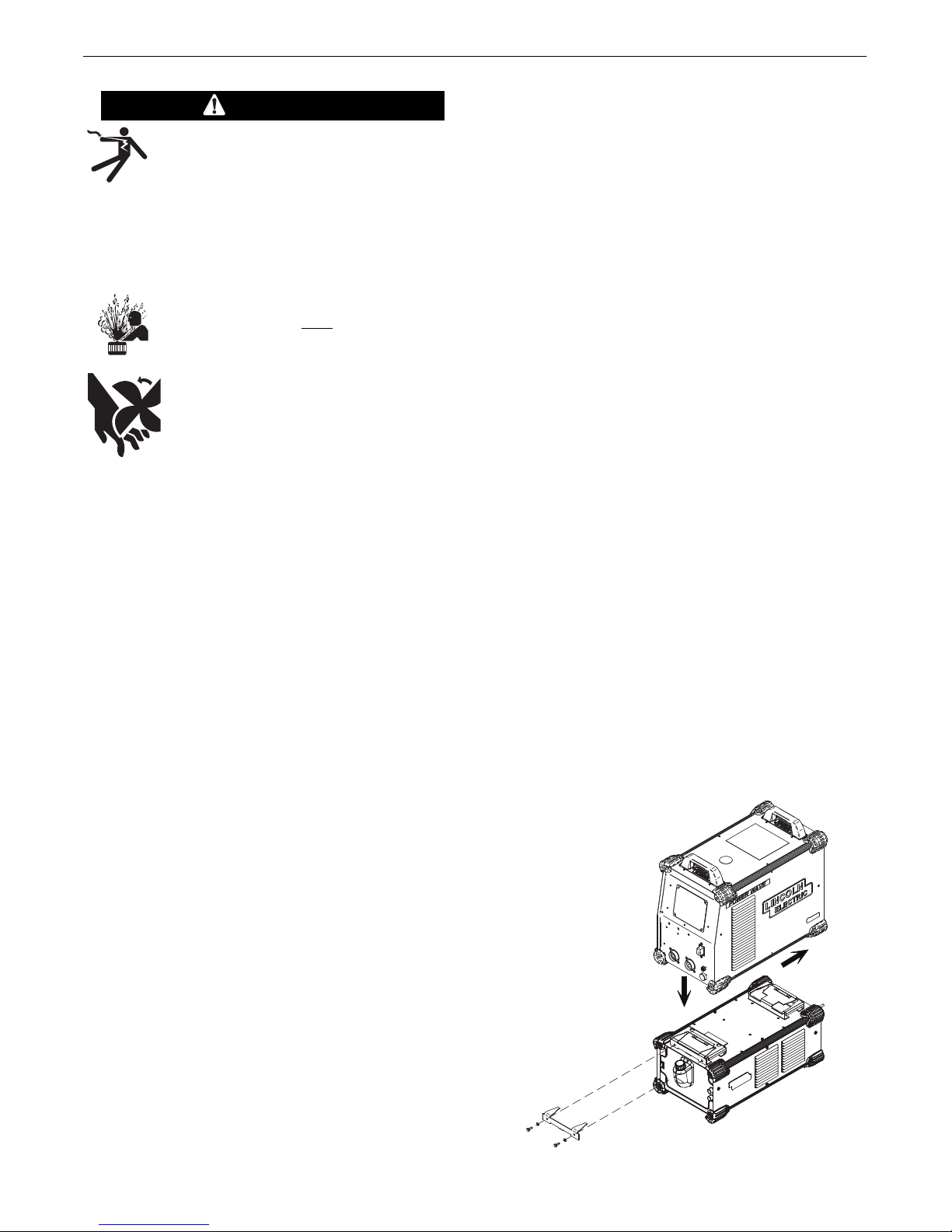
LOCATION AND MOUNTING
(See Figure A.1)
To mount the COOL ARC®55 to the bottom of a compatible
Power Wave “S” series power source utilize the quick lock
mechanism as shown.
f using the COOL ARC
I
such as the STT Module, always mount the COOL ARC
the bottom. The COOL ARC®55 will operate in harsh
environments and can be used outdoors. Even so, it is important
that simple preventative measures are followed in order to
assure long life and reliable operation.
• The machine must be located where there is free circulation
of clean air such that movement into and out of the louvers
will not be restricted.
• Dirt and dust that can be drawn into the machine should be
kept to a minimum. The use of air filters on the air intake is
not recommended because normal air flow may be
restricted. Failure to observe these precautions can result in
poor cooling performance.
• Keep the machine dry. Shelter from rain and snow. Do not
place on wet ground or in puddles.
• Always mount the COOL ARC®55 underneath other
machines. Never attach a module underneath the cooler.
• Do not mount the Power Wave “S” series power source and
COOL ARC®55 combination over combustible surfaces.
Where there is a combustible surface directly under
stationary or fixed electrical equipment, that surface shall be
covered with a steel plate at least .060” (1.6mm) thick,
which shall extend not less than 5.90” (150mm) beyond the
equipment on all sides.
• Avoid placing the cooler near areas of extreme heat.
• Avoid placing the cooler near a flux hopper or an area where
dust build-up is extreme.
®
5 in conjuntion with another module
5
FIGURE A.1
®
55 on
Readthis entire installation section before you start installation.
--------------------------------------------------------------------
INSTALLATION ON POWER SOURCE
The COOL ARC®55 can be used as a stand alone unit or
mounted directly to the bottom of the Power Wave “S” series
power source.
Always place the Cool Arc 55 on a level surface to avoid causing
the machine to topple over.
A-2
Page 9

INSTALLATIONCOOL ARC®55 & COOL ARC®55 ALUMINUM WATER COOLER
FILLING THE COOLANT RESERVOIR:
Recommended Coolant
• For Use Above Freezing: Clean tap, distilled or de-ionized
water.
For Use Below Freezing: 50% water and 50% pure ethylene
•
glycol (reagent or industrial grade) mixture.
• DO NOT USE: Automotive anti-freeze that contains rust
inhibitors or leak stoppers.
These coolants will damage the pump and block the small
internal passageways of the heat exchanger, affecting cooling
performance.
• DO NOT USE: Pre-packaged welding industry coolants. These
coolants may contain oil-based substances, which attack the
plastic components of the cooler. Once added to the cooler,
these substances are virtually impossible to purge from the
water lines and heat exchanger.
To avoid freeze damage and water leakage in shipment, the
COOL ARC®55 unit is delivered empty with no coolant in the
system. To fill the unit, locate the plastic screw on reservoir fill
cap at the front of the unit and remove by turning counterclockwise.
Clean tap water, distilled water, de-ionized water, a 50/50 mix of
pure ethylene glycol and water, or any other coolant specified by
the manufacturer of the water cooled product that the Cooler is
used with, can be added into the coolant reservoir. The opening
of the fill cap mates with most coolant containers but, to avoid
spillage of coolant, a funnel should be placed into the reservoir
hole when filling the COOL ARC®55.
CAUTION
DO NOT USE OIL BASED COOLANTS OR COOLANTS THAT CONTAIN RUST
INHIBITORS OR LEAK STOPPERS.
--------------------------------------------------------------------------------
UNPLUG THE COOLER BEFORE FILLING THE COOLANT RESERVOIR:
Carefully add 2.375 gallons (9 liters) of coolant through a funnel
into the coolant reservoir fill hole.
The cooler is "FULL" when the coolant lies just below the coolant
reservoir opening .
NOTE: DO NOT ADD MORE THAN 2.375 GALLONS (9
LITERS) OF COOLANT INTO THE RESERVOIR. The fill cap
contains a pressure release air hole, which must not be blocked
by overfilling the reservoir with coolant.
Be certain to replace the reservoir fill cap when the reservoir is
full. Operation of the COOL ARC®55 without the fill cap in place
can cause poor cooling efficiency, evaporation loss of coolant
and reduced product life.
NOTE: Pure solutions and mixtures of, or materials (i.e.
towels) wetted with ethylene glycol are toxic to humans and
animals. They must not be haphazardly discarded, especially by
pouring liquids down the drain. Contact the local EPA office for
responsible disposal methods or for recycling information.
For best results when using the COOL ARC®55 with Lincoln guns
or torches, use distilled or de-ionized water, although if not
available, tap water can be used. If protection from freezing is
desired, use a 50% water and 50% pure ethylene glycol (reagent
or industrial grade) mixture. An alcohol and water mixture is also
acceptable.
®
When using the COOL ARC
55 with other products, consult the
manufacturer's instruction manual for recommended coolants.
A-3
Page 10

INSTALLATIONCOOL ARC®55 & COOL ARC®55 ALUMINUM WATER COOLER
COOLANT
IN
COOLANT
OUT
FFRROOMM HHEEAATT
SSOOURCURCEE ((RREEDD))
TTOO HHEEAATT
SSOOURCURCEE ((BBLLUUEE))
COOLANT "IN" AND "OUT" CONNECTIONS
The fittings located on the COOL ARC®55 are two female Quick
Disconnect fittings. These mate with water hoses typically
used in the welding industry. Two couplers converting from
quick disconnect to 5/8-18 left-hand thread (CGA style) are also
included.
Refer to Figure A.2.
Water or Coolant Line Connections
to the
COOL ARC®55
Take the male quick disconnect of the water hose and check if it
matches the coupler or the quick disconnect on the front of the
unit. When using water hoses with threaded nuts use the
supplied couplers to convert from 5/8-18 left hand female thread
to male quick disconnect.
(Reference FIG. A.2) Take the accessory "INLET" hose (colored
or tagged blue on most hoses) and plug it into the coolant "OUT"
fitting located on the front of the cooler. If necessary use the
supplied coupler, making sure to secure the connector nut of the
hose tightly into the fitting with a wrench so that leaking does
not occur. Then take the accessory "OUTLET" hose (colored or
tagged red on most hoses) and plug it into the coolant "IN" fitting
located on the front of the cooler. Again, if necessary use the
coupler, tightly securing the connector nut of the hose into the
fitting with a wrench to insure that no leaking occurs.
INPUT POWER CONNECTION
Plug the input power cord on the COOL ARC®55 into a standard
115V NEMA circuit breaker protected receptacle. The receptacle
must have overload protection and a grounding conductor pin.
NOTE: BE CERTAIN THAT NO LEAKS EXIST WHEN THE COOLER
IS TURNED ON. A LEAK WILL DEPLETE RESERVOIR VOLUME,
CAUSING POOR COOLING PERFORMANCE AND REDUCING
GUN OR TORCH LIFE.
FIGURE A.2
Inlet and Outlet Hose Connection Diagram
A-4
Page 11

INSTALLATIONCOOL ARC®55 & COOL ARC®55 ALUMINUM WATER COOLER
C
O
O
L
A
N
T
C
O
O
L
A
N
T
TO WORK
COOLANT
OUT
COOLANT
IN
=
BLUE HOSE
= RED HOSE
G
A
S
GAS
K1622-4 ADAPTER
FEMALE
TO FEMALE
CGA FITTING
K
P5
04 WATER HOSES AND
F
EMALE TO FEMALE
5/8" LH
CGA ADAPTER COUPLINGS
FEMALE TO FEMALE
CGA FITTING
COOLANT
COOLANT
GUN CABLE
COOLANT
OUT
COOLANT
IN
= BLUE HOSE
= RED HOSE
COOLANT
OUT
COOLANT
IN
= BLUE HOSE
= RED HOSE
COOLANT
COOLANT
GUN CABLE
C
O
O
L
A
N
T
C
O
O
L
A
N
T
TO WORK
GAS
ELECTRODE CABLE
NOTE:
ORDER K1859-1 FOR WIRE
FEEDERS WITH QUICK
DISCONNECT FITTINGS.
CONTOL
CABLE
COOLANT
OUT
COOLANT
IN
= BLUE HOSE
= RED HOSE
K1859-1 FOR
CONNECTING TO
WIRE FEEDERS
COOLANT
COOLANT
COOLANT
COOLANT
GUN CABLE
INSTALLATION OF WATER COOLED ACCESSORIES
After following the installation instructions above, the COOL ARC
5 is ready for connection to a water-cooled accessory.
5
WATER COOLED TIG TORCH AND MIG GUN
®
Follow Figure A.3 when using the COOL ARC
55 with watercooled TIG torches. Follow Figure A.5 when using the COOL
ARC®55 with water-cooled MIG gun. Consult the manufacturer's
nstruction manual when using the COOL ARC
i
®
5 with other
5
water-cooled TIG and MIG accessories.
CONNECTION TO WIRE FEEDERS
®
Follow Figure A.4 when using the COOL ARC
55 in conjunction
with a wire feeder. The feeder will need to have pass-through
water hoses installed in order to correctly function with the COOL
ARC®55, since the cooler requires continuous flow. DO NOT USE
A WATER SOLENOID VALVE with the COOL ARC®55. Water passthrough connection kits are available for wire feeders. Refer to
product literature or the wire feeder's instructions manual for kit
availability and further connection details. It is not required to run
the water lines through the wire feeder, but is does provide a
very neat MIG gun connection. If pass-through water hoses are
unavailable, connect the MIG gun as shown in
Figure A.5.
CAUTION
DO NOT USE A WATER SOLENOID VALVE with the COOL ARC
55. When a solenoid valve closes, the pump would deadhead, causing the pump to heat up excessively leading to
premature failure of the pump.
®
K529-10 POWER INPUT CABLE WITH WATER AND GAS HOSES
This cable assembly includes a (1) power cable, (1) control
cable, (1) gas hose and (2) water hoses to connect a power
ource to a wire feeder. The cable length is 10'. The water hoses
s
have 5/8"-18 left hand male hose fittings and the gas hose has a
5/8"-18 right hand male hose fitting. The cable and hose lengths
are designed to connect a wire feeder to a COOL ARC
to Figure A.6 for an illustration of this connection.
FIGURE A.5
Connection to Wire Feeder (Do Not Use Water Solenoid)
®
®
55. Refer
FIGURE A.3
Water Cooled TIG Torch Connection
FIGURE A.4
Water Cooled MIG Gun Connection
FIGURE A.6
Connection to Wire Feeder (Do Not Use Water Solenoid)
A-5
Page 12

OPERATIONCOOL ARC®55 & COOL ARC®55 ALUMINUM WATER COOLER
SAFETY PRECAUTIONS
WARNING
ELECTRIC SHOCK can kill.
• Do not operate with covers removed.
• Do not opera te i f ca bl es a re wet or
immersed in water.
• Moving part s can injure . Neve r plac e
fingers into openings of Cooler.
• Hot coolant can burn skin. Always be sure
coolant is NOT HOT before servicing the
cooler.
• Do not pour used ethylene glycol coolant
down the drain.
---------------------------------------------------------
See additional warning information at front of
this operator’s manual.
---------------------------------------------------------
RECOMMENDED PROCESSES AND EQUIPMENT
Recommended Processes, Equipment and Accessories. The
COOL ARC®55 is designed for use with water-cooled TIG, MIG,
AC (Plasma Arc Cutting) and PAW (Plasma Arc Welding) guns
P
and torches. The COOL ARC
feeders and power sources as well as TIG power sources.
TURNING THE SYSTEM "ON"
Af ter connecting the COOL ARC®55 pe r t he installation
instructions above, plug the unit into a 115V NEMA electrical
receptacle for start-up operation. Be certain that the power input
into the unit matches the Cooler's rated input.
The LIGHTED POWER SWITCH is located on the left side of the
control panel. The cooler will be "ON" when pressed to " l " and
"OFF" when pressed to "O".
in the "ON" position.
You will be able to hear the fan running and feel airflow out of
the sides of the unit when the cooler is operating. The cooler will
run continuously unless it is plugged into a switched receptacle
on the power source.
®
55 can be used with MIG wire
The switch will also illuminate when
PRODUCT DESCRIPTION
The COOL ARC®55 is a stand alone re-circulation cooling system
designed for use with water-cooled TIG, MIG, PAC (Plasma Arc
Cutting) and PAW (Plasma Arc Welding) guns and torches. The
coolant "IN" and "OUT" connections are female quick disconnect
fittings. The COOL ARC®55 is a continuous duty cooler.
The COOL ARC®55 is very easy to use and understand with only
one power switch on the control panel. The cooler has a standard 115 V power input receptacle, making it very easy to power
up. Adding coolant to the reservoir is simple and connecting to
the coolant "IN" and "OUT" connections are easily made by hand
with the quick disconnects.
The COOL ARC®55 coolant flow is circulated through a heat
exchanger to remove heat energy from the coolant. The coolant
flow is then deposited into the coolant reservoir. The pump
draws its coolant supply from the coolant reservoir and delivers
coolant to the welding torch or gun. Refer to Figure B.1 and
B.2.
B-1
Page 13

COOL ARC 55
RESERVOIR
PUMP
HEAT
EXCHANGER
FAN
WELD ING
GUN OR
TORCH
HEAT IN
HEAT
OUT
COOLANT IN
COOLANT OUT
C
O
O
L
A
N
T
C
O
O
L
A
N
T
R
OOM AIR IN
HOT
AIR
OUT
H
OT
AIR
OUT
PUMP
HEAT
EXCHANGER
FAN
RESERVOIR
OPERATIONCOOL ARC®55 & COOL ARC®55 ALUMINUM WATER COOLER
The coolant FLOW INDICATOR is accessed by removal of the fill cap.
Actual return flow is directly visible, via the fill opening.
When first starting the unit, check all of the coolant hoses to insure that
o water leaks are present. Water leakage causes poor welding
n
performance, poor cooling performance, low welding component life
and potential electrical safety hazards.
• The cooler should be turned "OFF" when welding is not taking
lace for long periods of time.
p
• Be certain that the cooler is "ON" (power switch in the "l" position)
before beginning to weld.
• Never operate the cooler with the reservoir fill cap removed. Unless
checking coolant flow.
• Avoid kinking or putting sharp bends in any water lines.
• Keep all water lines clean and free of any blockage.
• Do not operate cooler without coolant in reservoir. Never run pump
dry.
FIGURE B.1
Coolant Circulation Diagram
COOLING EFFICIENCY
®
he high cooling efficiency of the COOL ARC
T
5 offers a cooler, more
5
comfortable weld than conventional air-cooled procedures as well as
leading competitors water cooled systems.
®
he COOL ARC
T
5 effectively removes the heat of the arc away from
5
the gun or torch handle and places it into the exiting air flow at the sides
of the cooler. Ambient air temperature affects the coolant temperature
®
of the COOL ARC
55.
For example:
Unlike other water coolers that depend on a bulky reservoir size, the
high efficiency components of the COOL ARC®55 allows the reservoir
size to be small. The result is a lightweight, portable unit.
FIGURE B.2
B-2
Page 14

ACCESSORIESCOOL ARC®55 & COOL ARC®55 ALUMINUM WATER COOLER
OPTIONAL EQUIPMENT (FIELD INSTALLED)
K1536-1 Magnum Flow Sensor:
rotects valuable torches, guns and robotic welding systems
P
from damage when loss of coolant flow has occurred for any
reason such as a blocked or kinked water line or a ruptured
hose.
KP1529-1 Quick Connect Water Adapter:
Converts a male 5/8"-18 left hand hose fitting (CGA Style) to a
female quick connect fitting. The female quick connect mates
with the male quick connects on water cooled MIG guns or
hoses.
K1859-1 Water Cooler to Wire Feeder Hoses:
This kit includes two 25’(7.6m) – 3/16 I.D. water hoses with a
5/8" LH CGA st yle fitt in g on one end an d a male qui ck
disconnect on the other. Most wire feeders have female quick
disconnects and this kit allows direct hook up between the water
cooler and the wire feeder.
5/8"-18 Left Hand Male Hose Fitting Parts: (CGA Style)
Fittings that convert a standard 3/16" I.D. hose to a 5/8"-18 left
hand male hose fitting. These male hose fittings mate with the
fittings on the back of the COOL ARC®55.
KP504 TIG Hook Up Kit:
The Hook-Up Kit includes: (2) water hoses, (1) gas hose, (2)
water adapter fittings, male to male 5/8" LH thread, (1) water
hose coupler, female to female 5/8" LH thread and (1) power
cable adapter. Threads on all hoses and fittings are CGA style.
CAUTION
DO NOT USE A WATER SOLENOID VALVE with the COOL ARC
55. When a solenoid valve closes, the pump would deadhead, causing the pump to heat up excessively leading to
premature failure of the pump.
Coolant Hoses:
Coolant hoses are readily available from an industrial welding
supplier or in various MIG or TIG hook-up kits provided by
Lincoln Electric. Refer to Magnum accessory literature sheets.
For lengths of coolant hoses over 25Ft(7.6m). and up to
50Ft.(15.2m), 5/16 I.D. hose is recommended. 5/16 I.D. hose
and accommodating fittings are available from an industrial
welding supplier.
COOLANTS
®
Order the following:
(See Parts Lists for Item’s below)
(2) Connector Nuts
(2) Nipples for 3/16" I.D. Hose
(2) Hose Clamps
The connector and nipple listed fit tightly onto 5/32” (4.0mm) to
3/16" (4.8mm) inner diameter hose, but if clamped tightly to the
hose, can fit up to a .25” (6.4mm) inner diameter hose. These
fittings are also readily available from any industrial welding
supplier.
K529-10
Power Input Cable with Water and Gas Hoses:
This cable assembly includes the following: (1) power cable, (1)
control cable, (1) gas hose and (2) water hoses. The cable
assembly connects a power source to a wire feeder for watercooled MIG applications. The cable length is 10'(3.1m). The
water hoses have 5/8"-18 left hand male hose fittings and the
gas hose has a 5/8"-18 right hand male hose fitting. The cable
and hose lengths are designed to connect a wire feeder to a
®
COOL ARC
55 that is vertically mounted at the rear of a power
source on a dual cylinder undercarriage. Refer to Figure A.6 for
an illustration of this connection.
KP3379-1 Magnum®PRO AL Coolant:
May be used in aluminum push-pull systems where hi gh
frequency is NOT used.
KP4159-1 Low Conductivity Coolant:
May be used in MIG and TIG systems (but NOT aluminum pushpull) where high frequency may be present.
C-1
Page 15

MAINTENANCECOOL ARC®55 & COOL ARC®55 ALUMINUM WATER COOLER
SAFETY PRECAUTIONS
WARNING
Have qualified personnel do the maintenance work. In some
cases, it may be necessary to remove safety guards to perform
required maintenance. Remove guards only when necessary and
replace them when the maintenance requiring their removal is
omplete. Always use the greatest care when working near
c
moving parts.
--------------------------------------------------------------------------
• Disconnect input power by removing plug from receptacle
before working inside Cooler.
• Do not touch electrically “hot” parts inside Cooler.
• Have qualified personnel do the installation, maintenance and
troubleshooting work.
• Unplug the cooler before performing general maintenance.
---------------------------------------------------------
---------------------------------------------------------
Observe all Safety Guidelines detailed throughout this manual. Be
sure to disconnect the Cooler from the Power Source before
performing any maintenance procedures.
---------------------------------------------------------
ELECTRIC SHOCK can kill.
• Do not touch electrically live parts or electrode
with skin or wet clothing.
• Insulate yourself from work and ground
• Always wear dry insulating gloves.
MOVING PARTS can injure.
• Do not operate with doors open or guards off.
• Keep away from moving parts.
PUMP MAINTENANCE
The pump head has a "built in" strainer on the inlet side of the pump. It is
recommended to clean or replace the pump's inlet strainer at least
nce a year. (See Above):
o
• Drain the coolant reservoir and all coolant lines. Dispose of the coolant
properly as specified above.
Hold the pump head firmly to apply a counter-torque when loosing the
•
strainer's 7/8" acorn nut located on the bottom. Do not confuse with 3/4"
acorn nut. Remove nut and slide inlet strainer down and out from the
pump head.
• Gently rinse the strainer under running water to thoroughly clean it.
• Use a mirror to inspect the inside of the pump for contamination. Carefully
remove hardened debris with a den tal pick if necessary, without
scratching the inside of the pump.
• Reinstall the strainer and 7/8 acorn nut, tightening with 75+/-15 in-lbs. of
torque. Wipe dry all area wetted with coolant. Dispose of coolant soaked
towels properly as specified above.
• For a more in depth procedure, See “Maintenace Section”, “Pump Inlet
Strainer”.
PUMP MOTOR
The COOL ARC®55 is rated for continuous operation. It is recommended to
re-oil the pump motor bearings once a year as follows:
• Remove the plastic plugs located on the top of both the inboard and
outboard bearing end-caps.
• Re-oil each bearing with 30-35 drops of SAE 20 oil then reinstall both
plugs.
ROUTINE MAINTENANCE
Remove accumulated dust and dirt from the internal components of the
cooler by blowing it out with a low pressure air hose or removing it with a
vacuum hose.
PERIODIC MAINTENANCE
In dirty or dusty environments or if biological growth occurs in the coolant, it
may be necessary to flush the coolant reservoir. Drain the old coolant, rinse
the inside of the reservoir and circulate rinsing solution through the coolant
system. Add new coolant when cleaning is finished. It is recommended to
flush the coolant at least once a year. A cooling system free from debris
offers increased cooling efficiency and longer pump and torch life. See the
Coolant Treatment Recommendation in this “Maintenace Section”.
NOTE: Pure solutions, mixtures of, or materials (i.e. towels wetted) with
ethylene glycol are toxic to humans and animals.
They must not be haphazardly discarded, especially by pouring liquids down
the drain. Contact the local EPA office for responsible disposal methods or
for recycling information.
HEAT EXCHANGER
To maintain maximum cooler efficiency, the heat exchanger should be kept
free of dust and dirt build-up. Clean the heat exchanger periodically using a
vacuum hose or a low-pressure air line. Avoid placing the unit near a flux
hopper or a flux waste container. A clean heat exchanger offers better cooling
performance and longer product life. In extremely dirty environments, it may
be necessary to remove the heat exchanger completely from the cooler and
clean the fins with soap and water. Use care to avoid damaging the fins.
RESERVOIR COOLANT LEVEL
The reservoir volume should be checked daily before using the cooler.
Remove the reservoir fill cap and check the coolant level. The reservoir is
full when the coolant level is just below the reservoir fill opening. Keep the
reservoir full, especially after disconnecting the water lines or changing the
accessory being cooled.
D-1
Page 16

MAINTENANCECOOL ARC®55 & COOL ARC®55 ALUMINUM WATER COOLER
COOLANT TREATMENT RECOMMENDATION
This procedure is intended to provide a means of reducing the
objectionable amount of fungal and bacterial contamination that
has occurred in COOL ARC®55 water coolers and cooling systems.
Additive:
The recommended additive can be purchased at local pool
supply stores. An example is "Maintain Pool Pro 30% Non-Foam
Algaecide"
Limitations:
• This additive should be used with fresh coolants containing
only pure water.
• This additive should not be used with coolants containing any
other substance, including antifreeze substances.
• No other additives shall be used with the specified coolant that
has been treated with the recommended additive.
• This procedure is no permanent substitute for a periodic
maintenance schedule for the specified coolers
• A 1 quart bottle of additive is sufficient to disinfect and treat
about 500 coolers.
• Check with the manufacturer of your guns or torches to be
sure th at th is pr ocedure is compat ib le wi th yo ur
equipment.
Prepare the disinfectant:
Make a quantity of only what is needed to avoid an excess Bulk
preparation (for coolers serviced in quantity):
2.75 gals. (10.41 liters) of pure, fresh water per cooler 1.922 ml of
additive per cooler. Example: for 100 coolers, add 192.2 ml to 275.0
gals. of pure fresh water. Pour 2.375 gals. (9 liters) of disinfectant
into the empty reservoir. Recap the reservoir, tape over the air vent in
the cap, roll disinfectant around the inside the reservoir to thoroughly
coat all of its surfaces. Remove the tape from the reservoir cap.
Prime the cooling system by positioning cooler horizontally and
circulate disinfectant through it for 10 to 15 minutes. Drain disinfectant from the cooling system. Do not reuse this solution. Add new,
fresh coolant to the cooling system. Add 0.375 gals. (1.42 liters) of
fresh disinfectant to the system by pouring it into the reservoir, then
reduce the concentration to the nominal 30 ppm:
Add the balance 2.0 gals. (7.55 liters) of fresh, pure water to the
reservoir to create the treated coolant concentration. Prime the
cooling system.
PUMP INLET STRAINER
Poor cooler performance can usually be traced to a partially or
co mpletely blocked pump in le t s trainer. This is a userserviceable item and can be cleaned and reused, or replaced.
Continued pump operation with a blocked strainer can cause:
• Voiding of cooler service warranty
• Cavitation damage to the pump head’s inlet areas
• Welding accessory damage from overheating due to insufficient coolant flow rate.
A new or properly cleaned pump inlet strainer should restore the
cooler’s performance.
For additional service and periodic maintenance details and for
recommended coolants, follow the recommendations listed
below.
Procedure and Preparation:
WARNING
• Always switch off the COOL ARC®55 machine power
• Always disconnect the COOL ARC®55 machine from
service input power.
• Always allow the coolant in the system to cool enough to
avoid burn injuries.
• Avoid co ntact wi th conta minat ed coola nt . Wear
waterproof gloves and protective eye wear.
• Do not remove the pump relief valve’s 3/4 in. acorn hex
nut or attempt to adjust the relief valve setting.
---------------------------------------------------------
INSPECT CONDITION OF COOLANT
If coolant is contaminated or old:
• Drain the system of coolant and dispose of it in an environmentally responsible manner.
• Flush system of old coolant.
• Fill with fresh tap or distilled water, run for ten minutes, and
drain.
• Proceed to adding coolant..
If coolant is clean and fresh:
Check coolant level. Add more fresh, pure water if required, without
adding more than 0.125 gal. (0.475 liters) of pure water to prevent
diluting the coolant additive.
• If clean, dedicated coolant handling equipment, including a
clean siphon pump and a clean holding tank are available then
proceed to servicing the Pump Inlet Strainer.
D-2
Page 17

MAINTENANCECOOL ARC®55 & COOL ARC®55 ALUMINUM WATER COOLER
Removing Coolant:
a. Drain coolant from the reservoir using clean siphoning
equipment
b. Coolant level should be drained below the strainer’s pressure
fitting:
• This prevents coolant from streaming out of unit when
trainer nut is removed
s
SERVICE THE PUMP’S INLET STRAINER:
a. Place absorbent towels underneath pump head to prevent
stray coolant from wetting cooler’s electrical components.
b. See figure D.1. Hold pump head to apply countertorque when
loosening strainer’s 7/8 acorn nut. Do not confuse with 3/4
acorn nut. Remove nut and slide inlet strainer down and out
from pump head.
c. Inspect strainer for damage or excessive clogging:
• Replace or Gently rinse strainer under running water to
thoroughly clean it.
d. Use a mirror to inspect inside of pump for contamination. If
hardened debris is present and interferes with filter seating,
carefully remove it with dental pick without scratching inside
of the pump. Use care not to drop debris into pump.
e. Reinstall strainer and acorn nut, tightening with 75±15 in.-lbs.
of torque.
• Hold pump head to apply counter-torque when loosening
strainers 7/8 acorn nut.
f. Wipe dry all areas wetted by coolant. Dispose of towels in an
environmentally responsible manner.
Add coolant:
a. Add 2.375 gallons of coolant, either the recommendations off
the water cooled accessory or if none, see the design specification summary listed in this manual.
ADDITIONAL SERVICE NOTES:
1. Always use a back-up wrench on pump head when loosening
or tightening pump fittings.
2. Never run the pump dry. Always use a recommended coolant,
otherwise pump damage may result.
3. Fl ush coolant f rom system and rep lace with fre sh,
recommended coolant at least once a year. More frequent
flushing may be necessary, depending upon the user’s
particular system or its usage, especially if it is prone to
clogging from biological growth in the coolant.
FIGURE D.1
D-3
Page 18

TROUBLESHOOTINGCOOL ARC®55 & COOL ARC®55 ALUMINUM WATER COOLER
HOW TO USE TROUBLESHOOTING GUIDE
WARNING
Service and Repair should only be performed by Lincoln Electric Factory Trained Personnel. Unauthorized repairs
performed on this equipment may result in danger to the technician and machine operator and will invalidate your factory
warranty. For your safety and to avoid Electrical Shock, please observe all safety notes and precautions detailed
throughout this manual.
__________________________________________________________________________
This Troubleshooting Guide is provided to help you locate and
repair possible machine malfunctions. Simply follow the threestep procedure listed below.
Step 1. LOCATE PROBLEM (SYMPTOM).
Look under the column labeled “PROBLEM (SYMPTOMS)”. This
column describes possible symptoms that the machine may
exhibit. Find the listing that best describes the symptom that the
machine is exhibiting.
Step 2. POSSIBLE CAUSE.
The second column labeled “POSSIBLE CAUSE” lists the obvious
externa l possibilities tha t may c ontribute to the machine
symptom.
Step 3. RECOMMENDED COURSE OF ACTION
This column provides a course of action for the Possible Cause,
generally it states to contact your local Lincoln Authorized Field
Service Facility.
If you do not unders tand or ar e un able to pe rform the
Recommended Course of Action safely, contact your local
Lincoln Authorized Field Service Facility.
If for any reason you do not understand the test procedures or are unable to perform the tests/repairs safely, contact your Local Lincoln Authorized
Field Service Facility for technical troubleshooting assistance before you proceed.
CAUTION
E-1
Page 19

PROBLEMS
(SYMPTOMS)
Observe all Safety Guidelines detailed throughout this manual
POSSIBLE
CAUSE
TROUBLESHOOTINGCOOL ARC®55 & COOL ARC®55 ALUMINUM WATER COOLER
RECOMMENDED
COURSE OF ACTION
Cooler does not operate with power switch
"ON".
(Switch pushed to "I" position.)
Internal water leak.
Torch or gun runs hot.
Fan operates but there is low coolant flow.
1. Input cord unplugged.
2. Power switch faulty
3. Power harness damaged.
. Water lines blocked or crimped.
4
5. Leak in gun or water hoses.
6. Coolant reservoir empty.
7. The system needs to be primed
1. Hose clamp loose on one of internal
hoses.
2. Internal hose punctured.
3. Heat exchanger leaking.
4. Pump seal is leaking
1. Unit placed by area of extreme heat.
2. Low coolant flow.
3. No coolant flow.
4. Fan not operating.
5. Heat exchanger clogged.
1. Leak in torch/gun or hoses.
2.Torch/gun or hoses partially obstructed.
3. Reservoir empty or very low.
4. Pump strainer is dirty.
If all recommended possible areas of
misadjustment have been checked and the
problem persists, Contact your local
Lincoln Authorized Field Service Facility.
Fan operates but there is no coolant flow.
Pump operates, but fan does not.
Cooler trips outlet circuit breaker.
Cooler trips outlet circuit breaker.
1. Pump or pump motor failure.
2. Pump strainer is blocked.
1. Loose or disconnected fan lead.
2. Obstruction in fan blade.
3. Fan motor failure.
1. Circuit overloaded.
2. Fan or pump motor failure.
If for any reason you do not understand the test procedures or are unable to perform the tests/repairs safely, contact your Local Lincoln Authorized
Field Service Facility for technical troubleshooting assistance before you proceed.
CAUTION
E-2
Page 20

P1
M22842PRINT
ELECTRICAL SYMBOLS PER E1537
COLOR CODE: B - BLACK OR GRAY
W - WHITE
G - GREEN
G1 - FAN SHROUD GROUND
COOL ARC 55 WATER COOLER
CONNECTION(CUSTOMER
GROUND)
G2 - CASE BACK GROUND CONNECTION
G3 - CHASSIS GROUND CONNECTION
(FAN SHROUD)
P1 - INPUT POWER PLUG
SW1 - LIGHTED POWER SWITCH
MTR1 - PUMP MOTOR
MTR2 - FAN MOTOR
W
W
G
W
B
B
B
B
B
W
SW1
R
3
21
W
1
4
MTR1
MTR2
G1
G3
G2
A
INPUT: 115 V
60 HZ
TO GROUND
PER NATIONAL
ELECTRIC CODE
DIAGRAMSCOOL ARC®55 & COOL ARC®55 ALUMINUM WATER COOLER
F-1
panels. If the diagram is illegible, write to the Service Department for a replacement. Give the equipment code number.
NOTE: This diagram is for reference only. It may not be accurate for all machines covered by this manual. The specific diagram for a particular code is pasted inside the machine on one of the enclosure
Page 21

DIAGRAMSCOOL ARC®55 & COOL ARC®55 ALUMINUM WATER COOLER
L16090
F-2
Page 22

NOTESCOOL ARC®55 & COOL ARC®55 ALUMINUM WATER COOLER
F-3
Page 23

NOTESCOOL ARC®55 & COOL ARC®55 ALUMINUM WATER COOLER
F-4
Page 24

CUSTOMER ASSISTANCE POLICY
The business of The Lincoln Electric Company is manufacturing and
selling high quality welding equipment, consumables, and cutting
quipment. Our challenge is to meet the needs of our customers and
e
to exceed their expectations. On occasion, purchasers may ask
Lincoln Electric for advice or information about their use of our
products. We respond to our customers based on the best information
in our possession at that time. Lincoln Electric is not in a position to
warrant or guarantee such advice, and assumes no liability, with
respect to such information or advice. We expressly disclaim any
warranty of any kind, including any warranty of fitness for any
customer’s particular purpose, with respect to such information or
advice. As a matter of practical consideration, we also cannot assume
any responsibility for updating or correcting any such information or
advice once it has been given, nor does the provision of information
or advice create, expand or alter any warranty with respect to the sale
of our products.
Lincoln Electric is a responsive manufacturer, but the selection and
use of specific products sold by Lincoln Electric is solely within the
control of, and remains the sole responsibility of the customer. Many
variables beyond the control of Lincoln Electric affect the results
obtained in applying these types of fabrication methods and service
requirements.
Subject to Change – This information is accurate to the best of our
knowledge at the time of printing. Please refer to
www.lincolnelectric.com for any updated information.
TABLE OF CONTENTS
INSTALLATION
OPERATION
ACCESSORIES
MAINTENANCE
TROUBLESHOOTING
DIAGRAMS
 Loading...