

Page 1
M3044
09/2012
REV01
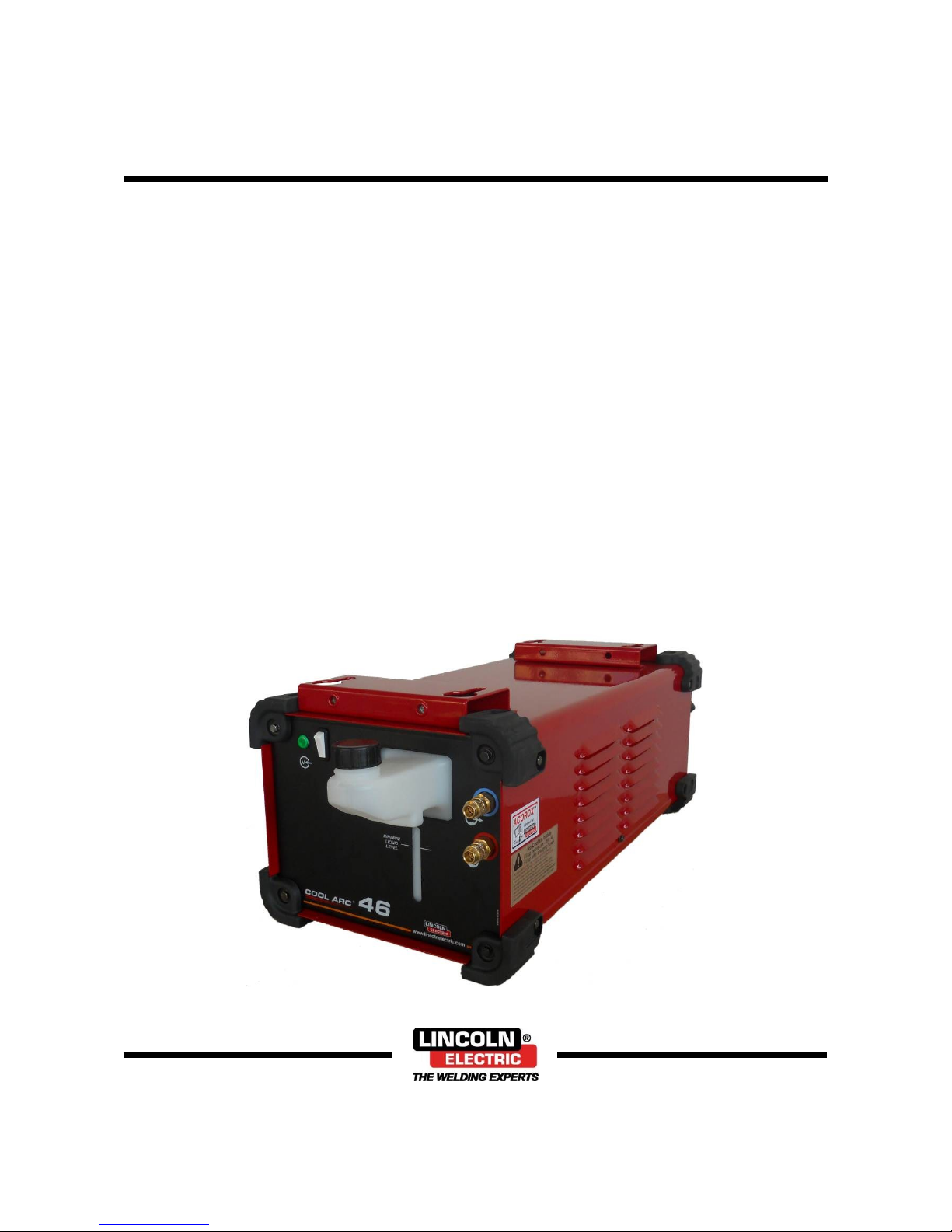
COOLARC 46
OPERATOR’S MANUAL
ENGLISH
Lincoln Electric Bester Sp. z o.o.
ul. Jana III Sobieskiego 19A, 58-263 Bielawa, Poland
www.lincolnelectric.eu
Page 2

English I English
Declaration of conformity
12
Lincoln Electric Bester Sp. z o.o.
Declares that the welding machine:
K14105-1
COOLARC 46
conforms to the following directives:
2006/95/CEE, 2004/108/CEE
and has been designed in compliance with the
following standards:
EN 60974-2, EN 60974-10:2007
27.04.2012
Paweł Lipiński
Operations Director
Lincoln Electric Bester Sp. z o.o., ul. Jana III Sobieskiego 19A, 58-263 Bielawa, Poland
12/05
Page 3
English II English
12/05
THANKS! For having chosen the QUALITY of the Lincoln Electric products.
Please Examine Package and Equipment for Damage. Claims for material damaged in shipment must be notified
immediately to the dealer.
For future reference record in the table below your equipment identification information. Model Name, Code & Serial
Number can be found on the machine rating plate.
Model Name:
………………………………………………………………………………………………………………………………………….
Code & Serial Number:
…………………………………………………………………..
…………………………………………………………………..
Date & Where Purchased
………………………………………………………………….
…………………………………………………………………..
ENGLISH INDEX
Safety .................................................................................................................................................................................. 1
Introduction ......................................................................................................................................................................... 2
Installation and Operator Instructions .................................................................................................................................. 2
Electromagnetic Compatibility (EMC) .................................................................................................................................. 7
Technical Specifications ...................................................................................................................................................... 8
WEEE.................................................................................................................................................................................. 9
Spare Parts ......................................................................................................................................................................... 9
Electrical Schematic ............................................................................................................................................................ 9
Accessories ......................................................................................................................................................................... 9
Page 4
English 1 English
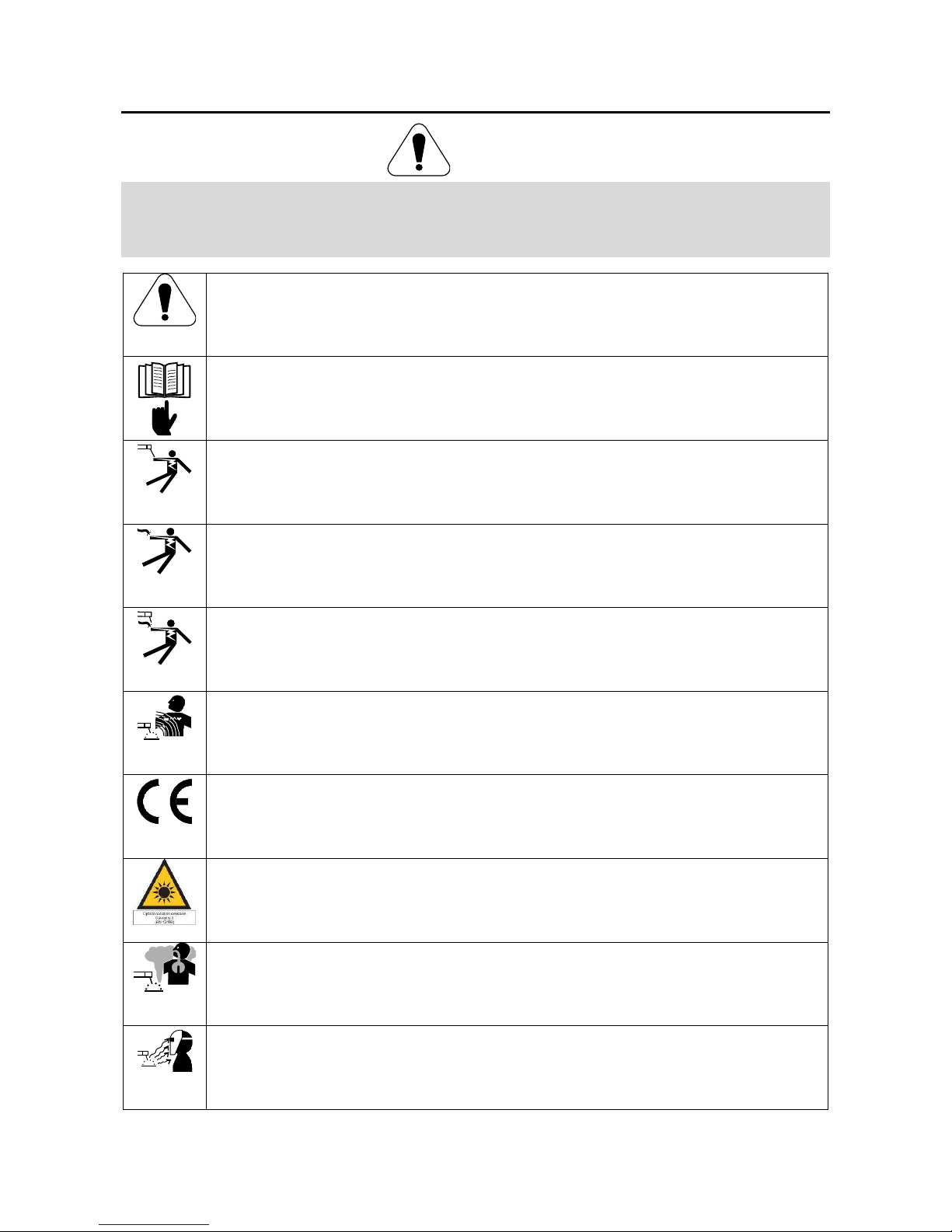
Safety
11/04
WARNING
This equipment must be used by qualified personnel. Be sure that all installation, operation, maintenance and repair
procedures are performed only by qualified person. Read and understand this manual before operating this equipment.
Failure to follow the instructions in this manual could cause serious personal injury, loss of life, or damage to this
equipment. Read and understand the following explanations of the warning symbols. Lincoln Electric is not responsible
for damages caused by improper installation, improper care or abnormal operation.
WARNING: This symbol indicates that instructions must be followed to avoid serious personal injury,
loss of life, or damage to this equipment. Protect yourself and others from possible serious injury or
death.
READ AND UNDERSTAND INSTRUCTIONS: Read and understand this manual before operating this
equipment. Arc welding can be hazardous. Failure to follow the instructions in this manual could cause
serious personal injury, loss of life, or damage to this equipment.
ELECTRIC SHOCK CAN KILL: Welding equipment generates high voltages. Do not touch the
electrode, work clamp, or connected work pieces when this equipment is on. Insulate yourself from the
electrode, work clamp and connected work pieces.
ELECTRICALLY POWERED EQUIPMENT: Turn off input power using the disconnect switch at the
fuse box before working on this equipment. Ground this equipment in accordance with local electrical
regulations.
ELECTRICALLY POWERED EQUIPMENT: Regularly inspect the input, electrode, and work clamp
cables. If any insulation damage exists replace the cable immediately. Do not place the electrode holder
directly on the welding table or any other surface in contact with the work clamp to avoid the risk of
accidental arc ignition.
ELECTRIC AND MAGNETIC FIELDS MAY BE DANGEROUS: Electric current flowing through any
conductor creates electric and magnetic fields (EMF). EMF fields may interfere with some pacemakers
and welders having a pacemaker shall consult their physician before operating this equipment.
CE COMPLIANCE: This equipment complies with the European Community Directives.
ARTIFICIAL OPTICAL RADIATION: According with the requirements in 2006/25/EC Directive and EN
12198 Standard, the equipment is a category 2. It makes mandatory the adoption of Personal Protective
Equipment (PPE) having filter with a protection degree up to a maximum of 15, as required by EN169
Standard.
FUMES AND GASES CAN BE DANGEROUS: Welding may produce fumes and gases hazardous to
health. Avoid breathing these fumes and gases. To avoid these dangers the operator must use enough
ventilation or exhaust to keep fumes and gases away from the breathing zone.
ARC RAYS CAN BURN: Use a shield with the proper filter and cover plates to protect your eyes from
sparks and the rays of the arc when welding or observing. Use suitable clothing made from durable
flame-resistant material to protect you skin and that of your helpers. Protect other nearby personnel with
suitable, non-flammable screening and warn them not to watch the arc nor expose themselves to the
arc.
Page 5

English 2 English
WELDING SPARKS CAN CAUSE FIRE OR EXPLOSION: Remove fire hazards from the welding area
and have a fire extinguisher readily available. Welding sparks and hot materials from the welding
process can easily go through small cracks and openings to adjacent areas. Do not weld on any tanks,
drums, containers, or material until the proper steps have been taken to insure that no flammable or
toxic vapors will be present. Never operate this equipment when flammable gases, vapors or liquid
combustibles are present.
WELDED MATERIALS CAN BURN: Welding generates a large amount of heat. Hot surfaces and
materials in work area can cause serious burns. Use gloves and pliers when touching or moving
materials in the work area.
CYLINDER MAY EXPLODE IF DAMAGED: Use only compressed gas cylinders containing the correct
shielding gas for the process used and properly operating regulators designed for the gas and pressure
used. Always keep cylinders in an upright position securely chained to a fixed support. Do not move or
transport gas cylinders with the protection cap removed. Do not allow the electrode, electrode holder,
work clamp or any other electrically live part to touch a gas cylinder. Gas cylinders must be located
away from areas where they may be subjected to physical damage or the welding process including
sparks and heat sources.
SAFETY MARK: This equipment is suitable for supplying power for welding operations carried out in an
environment with increased hazard of electric shock.
The manufacturer reserves the right to make changes and/or improvements in design without upgrade at the same time
the operator’s manual.
Introduction
The COOLARC 46 is a cooling system designed for use
witch water-cooler torches and guns:
GTAW torches
MGAW guns up to 500A.
The following equipment has been added to
COOLARC 46:
Hose with quick water connector – 0,2m.
COOLARC 46 is delivered empty with no coolant in the
system.
Recommended equipment, which can be bought by
user, was mentioned in the chapter "Accessories".
Installation and Operator Instructions
Read this entire section before installation or operation
of the machine.
Location and Environment
This machine will operate in harsh environments.
However, it is important that simple preventative
measures are followed to assure long life and reliable
operation:
Do not place or operate this machine on a surface
with an incline greater than 15° from horizontal.
Do not use this machine for pipe thawing.
This machine must be located where there is free
circulation of clean air without restrictions for air
movement to and from the air vents. Do not cover
the machine with paper, cloth or rags when switched
on.
Dirt and dust that can be drawn into the machine
should be kept to a minimum.
This machine has a protection rating of.IP23. Keep it
dry when possible and do not place it on wet ground
or in puddles.
Locate the machine away from radio controlled
machinery. Normal operation may adversely affect
the operation of nearby radio controlled machinery,
which may result in injury or equipment damage.
Read the section on electromagnetic compatibility in
this manual.
Do not operate in areas with an ambient temperature
greater than 40°C.
Input Supply Connection
The COOLARC 46 could be supplied by welding power
source using 9-PIN socket.
To connect the input supply to the COOLARC 46, turn
off the power to the welding power source and
disconnect it from the input supply.
The allowable input voltages are 230V/400V, 50/60Hz.
Make sure that the supply voltage of the unit matches
the cooler’s rated voltage.
WARNING
Do not switch on the welding power source with the
cooler applied if the reservoir was not filled and the
torch’s/gun’s hoses are disconnected from the cooling
unit. The no observance of this warning may be cause
internal damages at the cooler unit.
Page 6

English 3 English
Controls and Operational Features
FLOW
SENSOR
OFF
MINIMUM
LIQUID
LEVEL
2
4
5
3
1
6
Figure 1.
1. Power Indicator Light: This lamp will light
up to indicate that the cooler is supplied
by the power source.
2. Flow Sensor off Switch: Turn the coolant flow sensor
off. This switch can be used only when the pump has
to be primed and the cooler has to be bled (see "First
use of the cooler and bleeding cooling system").
WARNING
Incorporated into the cooler is an automatic flow sensor
to detect low or no coolant flow. A low or no flow
condition will cause welding output to automatically stop
to protect the torch.
3. Reservoir for Coolant with Nut: The translucent
reservoir enables control of value of the coolant.
4. Quick Connect Coupling: Coolant outlet
(supplies cool coolant to the torch/gun).
5. Quick Connect Coupling: Coolant inlet
(takes warm coolant from torch/gun).
6. Minimum Liquid Level: Determine the level of coolant
in which the cooler can work.
78
9
Figure 2.
7. Fuse: Use the 2A slow-blow fuse (see "Spare Parts"
section).
8. Power Lead with 9-PIN Socket.
9. Airflow Slots: Enable proper circulation of air cooling
(Figure.3).
Figure 3.
WARNING
Moving parts can injure. Never place fingers into the
openings of the Cooler.
WARNING
Avoid placing the cooler near a flux hopper or an area
where dust build-up is extreme.
Circulation of Coolant in the Cooler
Figure 4.
Warning: The ambient air temperature influences the
parameters of cooling. If the ambient temperature is
higher, the cooling system will be less effective.
WARNING
Avoid placing the cooler near areas of extreme heat.
Preparation COOLARC 46 to Work
Fill the coolant reservoir.
Connect COOLARC 46 to power source.
Turn the power source on.
Warning: First use the cooler require the pump is
primed by coolant.
Turn power source off.
Connect the water-cooler hoses to the cooler’s inlet
[5] and outlet [4] socket (Figure 6).
Turn the power source on.
Warning: The water-cooler hoses can require
bleeding.
Page 7

English 4 English
Coolant and Filling the Reservoir
WARNING
Before filling the coolant reservoir, disconnect cooler’s
power lead to the power source.
WARNING
Avoid contact with coolant. Wear waterproof gloves and
protective eye wear.
Warning: The cooler can be filled and used only in the
horizontal position.
Acorox is recommended coolant for COOLARC 46 (see
"Accessories" chapter).
Do not use pre-packaged welding industry coolants.
These coolants may contain oil-based substances,
which attack the plastic components of the cooler. Once
added to the cooler, these substances are impossible to
purge from the water lines and heat exchanger.
Do not use automotive anti-freeze. These coolants will
damage the pump and block of the heat exchanger,
affecting cooling performance.
WARNING
The coolant reservoir can be filled maximum 6l coolant.
Minimum 4l of coolant has to be poured into the
reservoir.
WARNING
Never operate the cooler with the reservoir empty.
WARNING
Do not start cooler with coolant less than 4l.
Too less volume of coolant can not be enough to full
priming of the system and may damage the pump.
Priming Pump (only first use the
cooler) and Bleeding the Cooling
System
Figure 5.
Assemble the welding set.
Connect the hose with quick water connector (added
to the equipment) to the cooler’s inlet and outlet
socket (Figure 5).
Fill the coolant reservoir – minimum 4l.
Undo the nut.
WARNING
At first using of the COOLARC 46 reservoir’s nut has to
be removed to avoid generate partial vacuum in cooling
system during priming pump.
Turn the power source on.
Force circulation of coolant: simultaneously press
and hold the flow sensor off switch [2] and
torch’s/gun’s trigger until the coolant does not
circulate the cooling system and does not return the
reservoir.
Turn the power source off.
Disconnect the hose with quick water connector.
Connect the water-cooler hoses – Figure 6.
Turn the power source on.
Force circulation of coolant: simultaneously press
and hold the flow sensor off switch [2] and
torch’s/gun’s trigger until the coolant does not
circulate the cooling system and does not return the
reservoir.
Tighten the nut.
WARNING
After priming pump and/or bleeding the cooling system,
be sure the reservoir’s nut is tightened up. Operation of
the cooler without the nut is tightened, can cause poor
cooling efficiency, evaporation loss of coolant, and low
product life.
The welding set is ready to work.
Connecting the Cooling System Hoses
The power source has to be turned off.
Connect the "outlet" hose of torch/gun
(colored or tagged red on most hoses)
into the inlet quick connect coupling [5]
located on the front panel of the cooler.
Connect the "inlet" hose of torch/gun
(colored or tagged blue on most hoses)
into the outlet quick connect coupling [4]
located on the front panel of the cooler.
Figure 6.
Warning: The water-cooler hoses are connected into
the quick connect coupling type 21KATS09MPX (see
"Spare parts" chapter), which are equipped with
automatic outflow blockade.
Before water-cooler hoses installing to the cooler, you
should check if the water-cooler hoses connectors match
to the quick connect coupling located on the front panel
of the cooler.
Page 8

English 5 English
WARNING
Avoid kinking or putting sharp bends in any water lines.
WARNING
Keep all water lines clean and free of any blockage.
Transport
To avoid freeze damage and water leakage during
transport, the coolant has to be removed from the
cooler’s reservoir.
Maintenance
WARNING
For any repair operations, modifications or
maintenances, it is recommended to contact the nearest
Technical Service Center or Lincoln Electric. Repairs
and modifications performed by unauthorized service or
personnel will cause, that the manufacturer’s warranty
will become null and void.
Any noticeable damage should be reported immediately
and repaired.
Routine maintenance (everyday)
Check condition of water-cooler hoses, connections
of the power lead.
Check the welding torch / gun condition: replace it, if
necessary.
Check condition and operation of the cooling fan.
Keep clean its airflow slots.
The reservoir volume should be checked daily before
using the cooler!!
Keep the reservoir full, especially after disconnecting
the water lines or changing the accessory being
cooled.
Periodic maintenance (not less than once a year)
Perform the routine maintenance and, in addition:
Keep the machine clean. Using a dry (and low
pressure) airflow, remove the dust from the external
case and from the cabinet inside.
In dirty or dusty environments or if biological growth
occurs in the coolant, it may be necessary to flush
the coolant reservoir. Drain the old coolant, rinse the
inside of the reservoir and circulate rinsing solution
through the coolant system. Add new coolant when
cleaning is finished.
WARNING
Hot coolant can burn skin. Always be sure coolant is
NOT HOT before servicing the cooler.
WARNING
Special precautions have to be taken when
the coolant is removed from the cooler
reservoir. The coolant must not be poured
out into ground water, sewerage, soil.
Read "Material Safety Data Sheet" (coolant
used) and contact the local Department of
Environmental Protection office to obtain
information on recycling coolant.
The frequency of the maintenance operations may vary
in accordance with the working environment where the
machine is placed.
WARNING
Do not touch electrically live parts.
WARNING
Before the case of machine will be removed, the
machine had to be turned off and the power lead had to
be disconnected from mains socket.
WARNING
Mains supply network must be disconnected from the
machine before each maintenance and service. After
each repair, perform proper tests to ensure safety.
Page 9

English 6 English
Troubleshooting
This Troubleshooting Guide is designed to be used by the machine Owner/Operator. Unauthorized repairs performed on
this equipment may result in danger to the technician and machine operator and will invalidate your factory warranty. For
your safety, please observe all safety notes and precautions detailed in the Safety Section of this manual to avoid
electrical shock or danger while troubleshooting this equipment.
WARNING
If for any reason you do not understand the test procedures or are unable to perform the tests/repairs safely, contact the
nearest authorized Technical Service Center or Lincoln Electric for technical troubleshooting assistance before you
proceed.
Cooler does not
operate.
Power lead unplugged.
No power at outlet.
Power lead is damaged.
Water lines blocked or crimped.
Leak in gun or water hoses.
Reservoir empty.
Plug in power lead.
Check outlet circuit breaker.
Repair damaged lead or order new lead
set.
Clear blockage in hose. Avoid kinking or
putting sharp bends in water lines.
Repair leak.
Fill reservoir.
Internal water leak.
Hose clamp loose on one of internal
hoses.
Internal hose punctured.
Heat exchanger leaking.
Tighten or replace hose clamp.
Replace punctured hose with new hose.
Replace heat exchanger.
Leak at inlet/outlet
connector block.
Hose clamp loose.
Tighten hose clamp onto hose.
Torch or gun runs hot.
Unit placed by area of extreme heat.
Low coolant flow.
No coolant flow.
Fan not operating.
Move unit away from hot air.
See Low Coolant Flow Section.
See No Coolant Flow Section.
Reference fan section.
Fan operates but there
is low coolant flow.
Leak in torch/gun or hoses.
Torch/gun or hoses partially obstructed.
Reservoir empty or very low.
Repair leak.
Clear obstruction.
Refill reservoir.
Fan operates but there
is no coolant flow.
Pump failure.
Pump seized.
Replace pump.
Replace pump.
Pump operates, but
fan does not.
Fan blade contacting heat exchanger.
Fan motor failure.
Replace fan.
Replace fan.
Cooler trips outlet
circuit breaker.
Circuit overloaded.
Cooler electrical component failure.
Check outlet circuit breaker.
Replace suppressor assembly and rectifier
inside of cooler.
Page 10

English 7 English
Electromagnetic Compatibility (EMC)
11/04
This machine has been designed in accordance with all relevant directives and standards. However, it may still generate
electromagnetic disturbances that can affect other systems like telecommunications (telephone, radio, and television) or
other safety systems. These disturbances can cause safety problems in the affected systems. Read and understand this
section to eliminate or reduce the amount of electromagnetic disturbance generated by this machine.
This machine has been designed to operate in an industrial area. To operate in a domestic area it is
necessary to observe particular precautions to eliminate possible electromagnetic disturbances. The
operator must install and operate this equipment as described in this manual. If any electromagnetic
disturbances are detected the operator must put in place corrective actions to eliminate these disturbances
with, if necessary, assistance from Lincoln Electric.
Before installing the machine, the operator must check the work area for any devices that may malfunction because of
electromagnetic disturbances. Consider the following.
Input and output cables, control cables, and telephone cables that are in or adjacent to the work area and the
machine.
Radio and/or television transmitters and receivers. Computers or computer controlled equipment.
Safety and control equipment for industrial processes. Equipment for calibration and measurement.
Personal medical devices like pacemakers and hearing aids.
Check the electromagnetic immunity for equipment operating in or near the work area. The operator must be sure
that all equipment in the area is compatible. This may require additional protection measures.
The dimensions of the work area to consider will depend on the construction of the area and other activities that are
taking place.
Consider the following guidelines to reduce electromagnetic emissions from the machine.
Connect the machine to the input supply according to this manual. If disturbances occur if may be necessary to take
additional precautions such as filtering the input supply.
The output cables should be kept as short as possible and should be positioned together. If possible connect the
work piece to ground in order to reduce the electromagnetic emissions. The operator must check that connecting the
work piece to ground does not cause problems or unsafe operating conditions for personnel and equipment.
Shielding of cables in the work area can reduce electromagnetic emissions. This may be necessary for special
applications.
WARNING
The Class A equipment is not intended for use in residential locations where the electrical power is provided by the public
low-voltage supply system. There may be potential difficulties in ensuring electromagnetic compatibility in those
locations, due to conducted as well as radiated disturbances.
Page 11

English 8 English
Technical Specifications
NAME
INDEX
COOLARC 46
K14105-1
INPUT
Input Voltage U1
Input Amperes I
1max
COOLARC 46
230 V ± 10%
0,65 A
400 V ± 10%
Frequency
EMC Group / Class
COOLARC 46
50/60 Hz
II / A
PARAMETERS RATING
The cooling power of flow 1liter per minute at
temperature of 25°C
Maximum pressure rate
COOLARC 46
1 kW
0,4 MPa
PARAMETERS O FTHE COOLER’S RESERVOIR
Maximum reservoir capacity
Minimum required reservoir capacity
COOLARC 46
6 l
4 l
COOLANT
COOLARC 46
Recommended
coolant
Acorox
COOLARC 46
Do not use!!
Pre-packaged welding industry coolants. These coolants may contain
oil-based substances, which attack the plastic components of the
cooler. Once added to the cooler, these substances are impossible to
purge from the water lines and heat exchanger.
Automotive anti-freeze. These coolants will damage the pump and
block of the heat exchanger, affecting cooling performance.
PHYSICAL DIMENSIONS
Weight
Height
Width
Length
COOLARC 46
22,7 kg
255 mm
300 mm
700 mm
Protection Rating
Operating Humidity
(t=20°C)
Operating Temperature
Storage Temperature
IP23
≤ 90 %
from -10 ºC to +40 ºC
from -25 ºC to +55 ºC
Page 12

English 9 English
WEEE
07/06
Spare Parts
12/05
Part list reading instructions
Do not use this part list for a machine if its code number is not listed. Contact the Lincoln Electric Service
Department for any code number not listed.
Use the illustration of assembly page and the table below to determine where the part is located for your particular
code machine.
Use only the parts marked "●" in the column under the heading number called for in the assembly page (# indicate
a change in this printing).
First, read the Part List reading instructions above then refer to the "Spare Part" manual supplied with the machine,
which contains a picture-descriptive part number cross-reference).
Electrical Schematic
Refer to the "Spare Parts" manual supplied with the machine.
Accessories
K10420-1
Coolant Acorox (2x5l)
English
Do not dispose of electrical equipment together with normal waste!
In observance of European Directive 2002/96/EC on Waste Electrical and Electronic Equipment
(WEEE) and its implementation in accordance with national law, electrical equipment that has reached
the end of its life must be collected separately and returned to an environmentally compatible recycling
facility. As the owner of the equipment, you should get information on approved collection systems from
our local representative.
By applying this European Directive you will protect the environment and human health!
 Loading...