

Lincoln Electric Cool Arc 26 Operator's Manual
COOL ARC® 26
OPERATOR’S MANUAL
IM3101
12/2019
REV04
oln Electric Bester Sp. z o.o.
Linc
ul. Jana III Sobieskiego 19A, 58-263 Bielawa, Poland
ENGLISH

THANKS! For having chosen the QUALITY of the Lincoln Electric products.
Please Examine Package and Equipment in case of Damage. Claims for material damaged in shipment must be
notified immediately to the dealer.
For future reference record in the table below your equipment identification information. Model Name, Code & Serial
Number can be found on the machine rating plate.
Model Name:
………………...…………………………….…………………………………………………………………………………………..
Code & Serial number:
………………….……………………………………………….. …………………………………………………….……………..
Date & Where Purchased:
…………………………………………………………………... ……………………….…………………………………………..
12/05
INDEX
Technical Specifications ...................................................................................................................................................... 1
Electromagnetic Compatibility (EMC) .................................................................................................................................. 2
Safety .................................................................................................................................................................................. 3
Introduction ......................................................................................................................................................................... 5
Unpacking ........................................................................................................................................................................... 5
Installation on Power Source ............................................................................................................................................... 5
Installation and Operator Instructions .................................................................................................................................. 8
WEEE ............................................................................................................................................................................... 18
Spare Parts ....................................................................................................................................................................... 18
REACh .............................................................................................................................................................................. 18
Authorized Service Shops Location .................................................................................................................................. 18
Electrical Schematic .......................................................................................................................................................... 18
Accessories ....................................................................................................................................................................... 19
English English
I

Technical Specifications
NAME INDEX
COOL ARC® 26
Input Voltage U1 Input Amperes I
230 V ± 15%
COOL ARC® 26
COOL ARC® 26
COOL ARC® 26
COOL ARC® 26
COOL ARC® 26
COOL ARC® 26
COOL ARC® 26
Protection Rating
IP23 ≤ 90 %
The cooling power of flow 1liter per minute at
Maximum reservoir capacity Minimum required reservoir capacity
Recommended coolant FREEZCOOL - W000010167
Do not use!!
Weight Height Width Length
18 kg 680 mm 260 mm 150 mm
400 V ± 15%
440 V ± 15%
Frequency EMC Class
50/60 Hz A
temperature of 25°C
0,84 kW 0,47 MPa
PARAMETERS O FTHE COOLER’S RESERVOIR
4 liters 3 liters
Operating Humidity
(t=68°F=20°C)
K14182-1
INPUT
1max
1,5 A
1A
0,9A
PARAMETERS RATING
Maximum pressure rate
COOLANT
Pre-packaged welding industry coolants. These coolants may contain oilbased substances, which attack the plastic components of the cooler.
Once added to the cooler, these substances are impossible to purge
from the water lines and heat exchanger.
Automotive anti-freeze. These coolants will damage the pump and block
of the heat exchanger, affecting cooling performance.
PHYSICAL DIMENSIONS
Operating Temperature Storage Temperature
from 14 ºF to 104 ºF
(from -10 ºC to +40 ºC)
from -13 ºF to 131 ºF
(from -25 ºC to +55 ºC)
English 1 English
Electromagnetic Compatibility (EMC)
This machine has been designed in accordance with all relevant directives and standards. However, it may still generate
electromagnetic disturbances that can affect other systems like telecommunications (telephone, radio, and television) or
other safety systems. These disturbances can cause safety problems in the affected systems. Read and understand this
section to eliminate or reduce the amount of electromagnetic disturbance generated by this machine.
Consider the following guidelines to reduce electromagnetic emissions from the machine.
Connect the machine to the input supply according to this manual. If disturbances occur if may be necessary to take
additional precautions such as filtering the input supply.
The output cables should be kept as short as possible and should be positioned together. If possible connect the
work piece to ground in order to reduce the electromagnetic emissions. The operator must check that connecting the
work piece to ground does not cause problems or unsafe operating conditions for personnel and equipment.
Shielding of cables in the work area can reduce electromagnetic emissions. This may be necessary for special
applications.
WARNING
The Class A equipment is not intended for use in residential locations where the electrical power is provided by the public
low-voltage supply system. There may be potential difficulties in ensuring electromagnetic compatibility in those locations,
due to conducted as well as radiated disturbances.
11/04
English 2 English
Safety
01/11
WARNING
This equipment must be used by qualified personnel. Be sure that all installation, operation, maintenance and repair
procedures are performed only by qualified person. Read and understand this manual before operating this equipment.
Failure to follow the instructions in this manual could cause serious personal injury, loss of life, or damage to this equipment.
Read and understand the following explanations of the warning symbols. Lincoln Electric is not responsible for damages
caused by improper installation, improper care or abnormal operation.
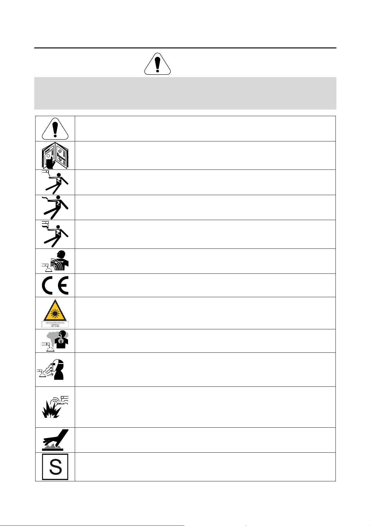
WARNING: This symbol indicates that instructions must be followed to avoid serious personal injury,
loss of life, or damage to this equipment. Protect yourself and others from possible serious injury or
death.
READ AND UNDERSTAND INSTRUCTIONS: Read and understand this manual before operating this
equipment. Arc welding can be hazardous. Failure to follow the instructions in this manual could cause
serious personal injury, loss of life, or damage to this equipment.
ELECTRIC SHOCK CAN KILL: Welding equipment generates high voltages. Do not touch the
electrode, work clamp, or connected work pieces when this equipment is on. Insulate yourself from the
electrode, work clamp, and connected work pieces.
ELECTRICALLY POWERED EQUIPMENT: Turn off input power using the disconnect switch at the
fuse box before working on this equipment. Ground this equipment in accordance with local electrical
regulations.
ELECTRICALLY POWERED EQUIPMENT: Regularly inspect the input, electrode, and work clamp
cables. If any insulation damage exists replace the cable immediately. Do not place the electrode
holder directly on the welding table or any other surface in contact with the work clamp to avoid the risk
of accidental arc ignition.
ELECTRIC AND MAGNETIC FIELDS MAY BE DANGEROUS: Electric current flowing through any
conductor creates electric and magnetic fields (EMF). EMF fields may interfere with some pacemakers,
and welders having a pacemaker shall consult their physician before operating this equipment.
CE COMPLIANCE: This equipment complies with the European Community Directives.
ARTIFICIAL OPTICAL RADIATION: According with the requirements in 2006/25/EC Directive and
EN 12198 Standard, the equipment is a category 2. It makes mandatory the adoption of Personal
Protective Equipments (PPE) having filter with a protection degree up to a maximum of 15, as required
by EN169 Standard.
FUMES AND GASES CAN BE DANGEROUS: Welding may produce fumes and gases hazardous to
health. Avoid breathing these fumes and gases. To avoid these dangers the operator must use
enough ventilation or exhaust to keep fumes and gases away from the breathing zone.
ARC RAYS CAN BURN: Use a shield with the proper filter and cover plates to protect your eyes from
sparks and the rays of the arc when welding or observing. Use suitable clothing made from durable
flame-resistant material to protect you skin and that of your helpers. Protect other nearby personnel
with suitable, non-flammable screening and warn them not to watch the arc nor expose themselves to
the arc.
WELDING SPARKS CAN CAUSE FIRE OR EXPLOSION: Remove fire hazards from the welding area
and have a fire extinguisher readily available. Welding sparks and hot materials from the welding
process can easily go through small cracks and openings to adjacent areas. Do not weld on any tanks,
drums, containers, or material until the proper steps have been taken to insure that no flammable or
toxic vapors will be present. Never operate this equipment when flammable gases, vapors or liquid
combustibles are present.
WELDED MATERIALS CAN BURN: Welding generates a large amount of heat. Hot surfaces and
materials in work area can cause serious burns. Use gloves and pliers when touching or moving
materials in the work area.
SAFETY MARK: This equipment is suitable for supplying power for welding operations carried out in
an environment with increased hazard of electric shock.
English 3 English

CYLINDER MAY EXPLODE IF DAMAGED: Use only compressed gas cylinders containing the correct
shielding gas for the process used and properly operating regulators designed for the gas and pressure
used. Always keep cylinders in an upright position securely chained to a fixed support. Do not move or
transport gas cylinders with the protection cap removed. Do not allow the electrode, electrode holder,
work clamp or any other electrically live part to touch a gas cylinder. Gas cylinders must be located
away from areas where they may be subjected to physical damage or the welding process including
sparks and heat sources.
HOT COOLANT CAN BURN SKIN: Always be sure coolant is NOT HOT before servicing the cooler.
The manufacturer reserves the Right to make changes and/or improvements in design without upgrade at the same time
the operator’s manual.
English 4 English

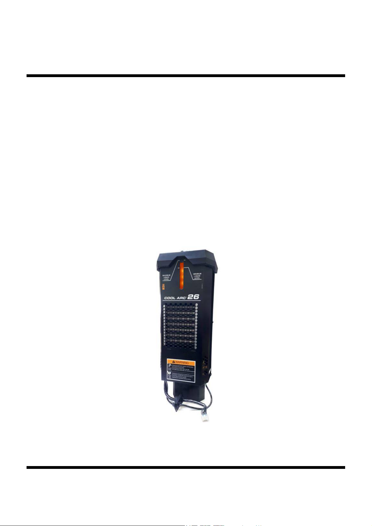
Introduction
COOL ARC
cooling system designed to use with MIG welding power
sources that lists the COOL ARC® 26 as an approved
accessory.
The following equipment is included with the
COOL ARC® 26:
Hose with quick water connector:
Blue (115 mm), Red (150 mm) hose for
Black hose that will be used in filing procedure
M5x20 screw for fixing to the power source by
spanner size 8.
®
26 cooler is a stand alone recirculating
connection to a welding source.
(200 mm)
Unpacking
Unpacking the COOL ARC® 26
The packaging of the Cooler is designed to withstand
shipping abuse, and contains a cardboard liner that
surrounds the unit. If any shipping damages have been
occurred, contact your certified Lincoln distributor or
service center.
Installation on Power Source
The COOL ARC® 26 need to be mounted directly to the
chassis of MIG welding power source that lists the
COOL ARC® 26 as an approved accessory.
WARNING
Only a qualified electrician can connect the welding
machine to the supply. Installation had to be made in
accordance with the appropriate National Electrical Code
and local regulations.
WARNING
Before connecting COOL ARC® 26 turn off the power
source and disconnect it from the input supply.
®
The COOL ARC
in the system. FREEZCOOL - W000010167 is
recommended.
When unpacking the unit, avoid thrusting sharp objects
through the carton liner, which may puncture the plastic
reservoir. Save the manual instruction and service
directory supplied with the COOL ARC
orders and future maintenance service.
INSTALATION:
Unscrew the side panel (Figure1)
Remove the side panel (Figure 2)
Unscrew and remove the cover bracket (Figure 3)
Place cooler in the base positioning pins (Figure 4)
Screw the cable holder bracket (Figure 5)
Connect the 10-pin plug to receptacle and screw
protective earth green/yellow wire terminal
(Figure 6).
Screw side panel (Figure 7)
Screw side panel. (Figure 8)
Final assembly (Figure 9)
26 is delivered empty with no coolant
®
26 for parts
English 5 English
 Loading...