

Page 1
IM10067
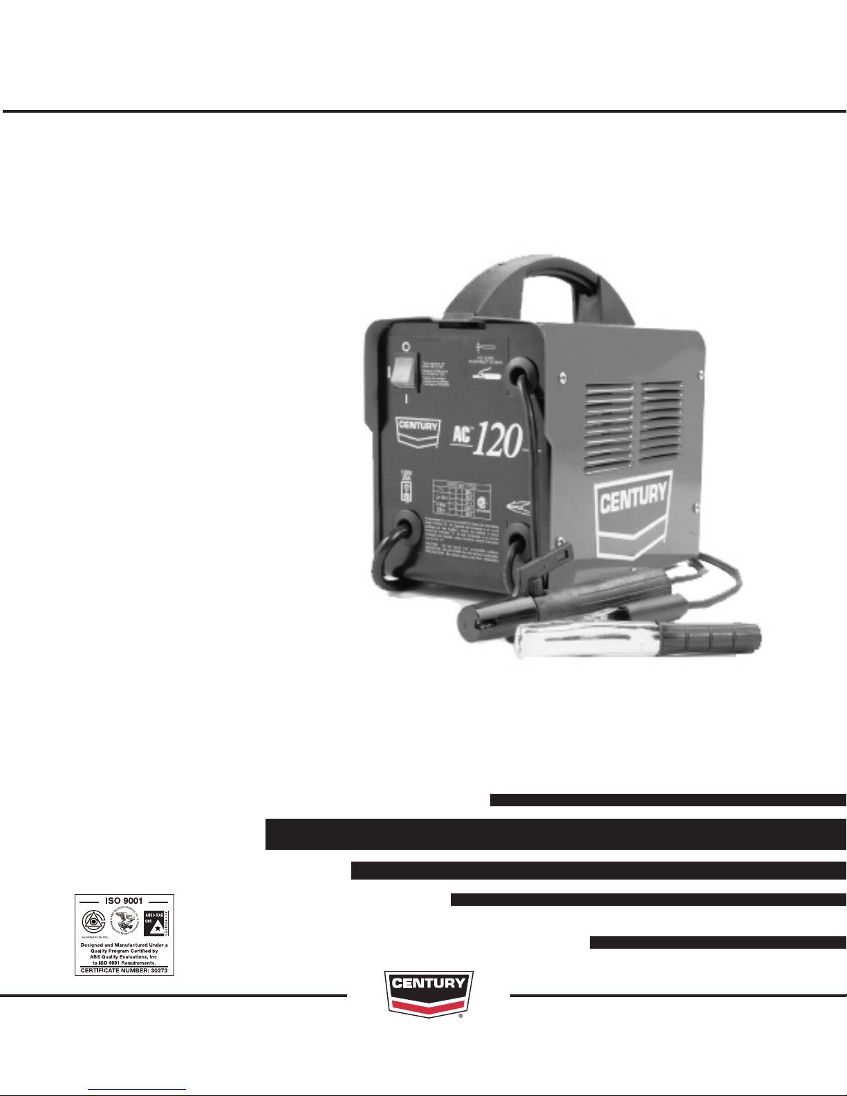
CENTURY AC 120
Safety Depends on You
Lincoln arc welding and cutting
equipment is designed and built
with saf ety in mind. However,
your overall safety can be
increased by proper installation
... and thoughtful operation on
your part. DO NOT INSTALL,
OPERATE OR REPAIR THIS
EQUIPMENT WITHOUT READING THIS MANUAL AND THE
SAFETY PRECAUTIONS CONTAINED THROUGHOUT. And,
most importantly, think before
you act and be careful.
®
May, 2010
OPERATOR’S MANUAL
2345 Murphy Blvd. Gainesville, GA 30504 TEL: 866-236-0044
Copyright © Lincoln Global Inc.
• Century®Equipment
11728 K2964-1
Web Site: www.centuryequipment.net
Page 2
i
SAFETY
WARNING
ALIFORNIA PROPOSITION 65 WARNINGS
C
Diesel engine exhaust and some of its constituents
are known to the State of California to cause cancer, birth defects, and other reproductive harm.
The Above For Diesel Engines
ARC WELDING CAN BE HAZARDOUS. PROTECT YOURSELF AND OTHERS FROM POSSIBLE SERIOUS INJURY OR DEATH.
EEP CHILDREN AWAY. PACEMAKER WEARERS SHOULD CONSULT WITH THEIR DOCTOR BEFORE OPERATING.
K
Read and understand the following safety highlights. For additional safety information, it is strongly recommended that you
purchase a copy of “Safety in Welding & Cutting - ANSI Standard Z49.1” from the American Welding Society, P.O. Box
351040, Miami, Florida 33135 or CSA Standard W117.2-1974. A Free copy of “Arc Welding Safety” booklet E205 is available
rom the Lincoln Electric Company, 22801 St. Clair Avenue, Cleveland, Ohio 44117-1199.
f
BE SURE THAT ALL INSTALLATION, OPERATION, MAINTENANCE AND REPAIR PROCEDURES ARE
PERFORMED ONLY BY QUALIFIED INDIVIDUALS.
The engine exhaust from this product contains
chemicals known to the State of California to cause
cancer, birth defects, or other reproductive harm.
The Above For Gasoline Engines
i
FOR ENGINE
powered equipment.
1.a. Turn the engine off before troubleshooting and maintenance
work unless the maintenance work requires it to be running.
____________________________________________________
1.b. Operate engines in open, well-ventilated
areas or vent the engine exhaust fumes
outdoors.
____________________________________________________
1.c. Do not add the fuel near an ope n flame
welding arc or when the engine is running.
Stop the engine and allow it to cool before
refueling to prevent spilled fuel from vaporizing on conta ct with hot engine parts and
igniting. Do not spill fuel when filling tank. If
fuel is spilled, wipe it up and do not start
engine until fumes have been eliminated.
____________________________________________________
1.d. Keep all equipment safety guards, covers and devices in
position and in good repair.Keep hands, hair, clothing and
tools away from V-belts, gears, fans and all other moving
parts when starting, operating or repairing equipment.
____________________________________________________
1.e. In some cases i t may b e neces sar y to remove safet y
gu a r d s to perf o r m requi r e d m ainte n a nce. Re m o v e
guards only when necessary and replace them when the
mai n t enanc e re q uirin g th eir r e m o val i s co m plete .
Always use the greatest care when working near moving
parts.
___________________________________________________
1.f. Do not put your hands near the engine fan.
Do not attempt to override the governor or
idler by pushing on the throttle control rods
while the engine is running.
1.h. To avoid scalding, do not remove the
radiator pressure cap when the engine is
hot.
ELECTRIC AND
MAGNETIC FIELDS
may be dangerous
2.a. Electric curr en t flowing through any conductor c au se s
localized E le ct ri c and Magn et ic Fields (EMF). Welding
current creates EMF fi el ds around welding cables and
welding machines
2.b. EMF fie lds may i nterf ere wit h some pacemak ers, and
welders having a pacemaker should consult their physician
before welding.
2.c. Exposure to EMF fields in welding may have other health
effects which are now not known.
2.d. All welders should use the following procedures in order to
minimize exposure to EMF fields from the welding circuit:
2.d.1.
Route the electrode and work cables together - Secure
them with tape when possible.
2.d.2. Nev er coi l the ele ctrode lead around your bod y.
2.d.3. Do not place your body between the electrode and
work cables. If the electrode cable is on your right
side, the work cable should also be on your right side.
___________________________________________________
1.g. To prevent accidentally starting gasoline engines while
turning the engine or welding generator during maintenance
work, disconnect the spark plug wires, distributor cap or
magneto wire as appropriate.
2.d.4. Connect the work cable to the workpiece as close as
possible to the area being welded.
2.d.5. Do not work next to welding power source.
Page 3
ii
SAFETY
ii
ELECTRIC SHOCK can
kill.
3.a. The electrode and work (or ground) circuits
are electrically “hot” when the welder is on.
Do not touch these “hot” parts with your bare
skin or wet clothin g. W ea r dry, hole-free
gloves to insulate hands.
3.b. Insulate yourself from work and ground using dry insulation.
Make certain the insulation is large enough to cover your full
area of physical contact with work and ground.
In addition to the normal safety precautions, if welding
mu s t be p e rformed unde r elec t rically haza r dous
conditions (in damp locations or while wearing wet
clothing; on metal structures such as floors, gratings or
scaffolds; when in cramped positions such as sitting,
kneeling or lying, if there is a high risk of unavoidable or
accidental contact with the workpiece or ground) use
the following equipment:
• Semiautomatic DC Constant Voltage (Wire) Welder.
• DC Manual (Stick) Welder.
• AC Welder with Reduced Voltage Control.
3.c. In semiautomatic or automatic wire welding, the electrode,
electrode reel, welding head, nozzle or semiautomatic
welding gun are also electrically “hot”.
3.d. Always be sure the work cable makes a good electrical
connection with the metal being welded. The connection
should be as close as possible to the area being welded.
3.e. Ground the work or metal to be welded to a good electrical
(earth) ground.
3.f.
Maintain the electrode holder, work clamp, welding cable and
welding machine in good, safe operating condition. Replace
damaged insulation.
3.g. Never dip the electrode in water for cooling.
3.h. Nev er simul tan eousl y touch ele ctric all y “ho t” parts of
electrode holders connected to two welders because voltage
between the two can be the total of the open circuit voltage
of both welders.
3.i. When working above floor level, use a safety belt to protect
yourself from a fall should you get a shock.
3.j. Also see Items 6.c. and 8.
ARC RAYS can burn.
4.a. Use a shield with the proper filter and cover
plates to protect your eyes from sparks and
the rays of the arc when welding or observing
open arc welding. Headshield and filter lens
should conform to ANSI Z87. I standards.
4.b. Use suitable clothing made from durable flame-resistant
material to protect your skin and that of your helpers from
the arc rays.
4.c. Protect other nearby personnel with suitable, non-flammable
screening and/or warn them not to watch the arc nor expose
themselves to the arc rays or to hot spatter or metal.
FUMES AND GASES
can be dangerous.
5.a. Weldi ng may produce fumes and gases
hazardous to health. Avoid breathing these
fumes and gases. When w elding, kee p
your head out of the fume. Use enough
ventilation and/or exhaust at the arc to keep
fumes an d gases away from the breathing zone. When
we l ding with electrod e s wh i ch re quire special
ve ntilat i on such as stainl ess or h ard facin g (see
instructio ns on container or MSDS) or on lead or
cadmium plated steel and other metals or coatings
which produce highly toxic fumes, keep exposure as
low as possible and within applicable OSHA PEL and
ACGIH TLV limits using local exhaust or mechanical
ventilation. In confined spaces or in some circumst ances, outd oors, a respir a tor may be requir e d.
Additional precautions are also required when welding
on galvanized steel.
5. b. The operation of welding fume control equipment is affected
by various factors including proper use and positioning of
the equipment, maintenance of the equipment and the specific welding procedure and application involved. Worker
exposure level should be checked upon installation and
periodically thereafter to be certain it is within applicable
OSHA PEL and ACGIH TLV limits.
5.c.
Do not weld in locations near chlorinated hydrocarbon
coming from degreasing, cleaning or spraying operations.
The heat and rays of the arc can react with solvent vapors
form phosgene, a highly toxic gas, and other irritating products.
5.d. Shielding gases used for arc welding can displace air and
caus e injur y or dea th. Alw ay s use eno ugh ven tilatio n,
especially in confined areas, to insure breathing air is safe.
vapors
to
5.e. Read and understand the manufacturer’s instructions for this
equipment and the consumables to be used, including the
mat e r ial s a f ety d a t a sh eet ( M S DS) a n d foll o w your
employer’s safety practices. MSDS forms are available from
you r wel d i n g di s t ribut o r or f rom th e ma n u factu r e r .
5.f. Also see item 1.b.
Page 4
iii
SAFETY
iii
WELDING and CUTTING
SPARKS can
cause fire or explosion.
6.a.
Remove fire hazards from the welding area.
If this is not possible, cover them to prevent
Re m e m ber th a t w eldin g s p arks a n d h ot
materials from welding can easily go through small cracks
an d o pen ings t o a djac ent area s. Avo id wel d ing near
hydraulic lines. Have a fire extinguisher readily available.
6.b. Where compressed gases are to be used at the job site,
special precautions should be used to prevent hazardous
situations. Refer to “Safety in Welding and Cutting” (ANSI
Standard Z49.1) and the op erating information for the
equipment being used.
6.c. When not welding, make certain no part of the electrode
circuit is touching the work or ground. Accidental contact
can cause overheating and create a fire hazard.
6.d. Do not heat, cut or weld tanks, drums or containers until the
proper steps have been taken to insure that such procedures
will not cause flammable or toxic vapors from substances
inside. They can cause an explosion even
been “cleaned”. For information, purchase “Recommended
Safe Practices for the
Co n t a iners and Piping That Have Held Haza r d o us
Substances”, AWS F4.1 from the American Welding Society
(see address above).
6.e. Vent hollow castings or containers before heating, cutting or
welding. They may explode.
Sparks and spatter are thrown from the welding arc. Wear oil
6.f.
free protective garments such as leather gloves, heavy shirt,
cuffless trousers, high shoes and a cap over your hair. Wear
ear plugs when welding out of position or in confined places.
Always wear safety glasses with side shields when in a
welding area.
6.g. Connect the work cable to the work as close to the welding
area as practical. Work cables connected to the building
framework or other locations away from the welding area
increase the po ss ib il it y of t he welding current passing
through lifting chains, crane cables or other alternate circuits. This can create fire hazards or overheat lifting chains
or cables until they fail.
6.h. Also see item 1.c.
the welding s pa rks fro m startin g a fire.
though
they have
Preparation
for Welding and Cutting of
CYLINDER may explode
if damaged.
7.a. Us e o n ly com p r e ssed g a s c ylind e r s
containing the correct shielding gas for the
pr o c e ss used a n d p r operl y o p erati n g
reg u l ators de signe d for t h e gas a n d
pressure used. All hoses, fittings, etc. should be suitable for
the application and maintained in good condition.
7.b. Alway s kee p cylin ders in an uprig ht pos ition s ecure ly
chained to an undercarriage or fixed support.
7.c. Cylinders should be located:
• Away from areas where they may be struck or subjected to
physical damage.
• A safe distance from arc welding or cutting operations and
any other source of heat, sparks, or flame.
7.d. Never allow the electrode, electrode holder or any other
electrically “hot” parts to touch a cylinder.
7.e. Keep your head and face away from the cylinder valve outlet
when opening the cylinder valve.
7.f. Valve protection caps should always be in place and hand
tight except when the cylinder is in use or connected for
use.
7.g. Rea d a nd follow t he ins tru cti ons on com pre sse d g as
cylinders, associated equipment, and CGA publication P-l,
“Precautions for Safe Handling of Compressed Gases in
Cylinders,” available from the Compressed Gas Association
1235 Jefferson Davis Highway, Arlington, VA 22202.
FOR ELECTRICALLY
powered equipment.
8.a. Turn off input power using the disconnect
switch at the fuse box before working on
the equipment.
8.b. Install equipm ent in acco rdance wi th the U. S. National
Electrical Code, all local codes a nd the manufacturer’s
recommendations.
8.c. Ground the equipment in accordance with the U.S. National
Electrical Code and the manufacturer’s recommendations.
6.I. Read and follow NFPA 51B “ Standard for Fire Prevention
During Welding, Cutting and Other Hot Work”, available
from NFPA, 1 Batterymarch Park, PO box 9101, Quincy, Ma
022690-9101.
6.j. Do not use a welding power source for pipe thawing.
Refer to http://www.lincolnelectric.com/safety for additional safety information.
Page 5

iv
SAFETY
iv
PRÉCAUTIONS DE SÛRETÉ
Pour
votre propre protection lire et observer toutes les instructions
et les précautions de sûreté specifiques qui parraissent dans ce
manuel aussi bien que les précautions de sûreté générales suivantes:
Sûreté Pour Soudage A L’Arc
1. Protegez-vous contre la secousse électrique:
a. Les circuits à l’électrode et à la piéce sont sous tension
quand la machine à souder est en marche. Eviter toujours
tout contact entre les parties sous tension et la peau nue
ou les vétements mouillés. Porter des gants secs et sans
trous pour isoler les mains.
b. Faire trés attention de bien s’isoler de la masse quand on
soude dans des endroits humides, ou sur un plancher
metallique ou des grilles metalliques, principalement dans
les positions assis ou couché pour lesquelles une grande
partie du corps peut être en contact avec la masse.
c. Maintenir le porte-électrode, la pince de masse, le câble
de soudage et la machine à souder en bon et sûr état
defonctionnement.
d.Ne jamais plonger le porte-électrode dans l’eau pour le
refroidir.
e. Ne jamais toucher simultanément les parties sous tension
des porte-électrodes connectés à deux machines à souder
parce que la tension entre les deux pinces peut être le
total de la tension à vide des deux machines.
f. Si on utilise la machine à souder comme une source de
courant pour soudage semi-automatique, ces precautions
pour le porte-électrode s’applicuent aussi au pistolet de
soudage.
2. Dans le cas de travail au dessus du niveau du sol, se protéger
contre les chutes dans le cas ou on recoit un choc. Ne jamais
enrouler le câble-électrode autour de n’importe quelle partie
du corps.
5. Toujours porter des lunettes de sécurité dans la zone de
soudage. Utiliser des lunettes avec écrans lateraux dans les
zones où l’on pique le laitier.
6. Eloigner les matériaux inflammables ou les recouvrir afin de
prévenir tout risque d’incendie dû aux étincelles.
7. Quand on ne soud
la masse. U n court-circuit accidental peut provoquer un
échauffement et un risque d’incendie.
8. S’assurer que la masse est connectée le plus prés possible
de la zone de travail qu’il est pratique de le faire. Si on place
la masse sur la charpente de la construction ou d’autres
endroits éloignés de la zone de travail, on augmente le risque
de voir passer le courant de soudage par les chaines de levage, câbles de grue, ou autres circuits. Cela peut provoquer
des risques d’incendie ou d’echauffement des chaines et des
câbles jusqu’à ce qu’ils se rompent.
9. Assurer une ventilation suffisante dans la zone de soudage.
Ceci est particuliérement important pour le soudage de tôles
galvanisées plombées, ou cadmiées ou tout autre métal qui
produit des fumeés toxiques.
10. Ne pas souder en présence de vapeurs de chlore provenant
d’o pérations de dégraissage, nettoyage ou pistolage . La
chaleur ou les rayons de l’arc peuvent réagir avec les vapeurs
du solvant pour produire du phosgéne (gas fortement toxique)
ou autres produits irritants.
11. Pour obtenir de plus amples renseignements sur la sûreté,
voir le code “Code for safety in welding and cutting” CSA
Standard W 117.2-1974.
e pas, poser la pince à une endroit isolé de
PRÉCAUTIONS DE SÛRETÉ POUR
3. Un coup d’arc peut être plus sévère qu’un coup de soliel,
donc:
a. Utiliser un bon masque avec un verre filtrant approprié
ainsi qu’un verre blanc afin de se protéger les yeux du rayonnement de l’arc et des projections quand on soude ou
quand on regarde l’arc.
b. Porter des vêtements convenables afin de protéger la
peau de soudeur et des aides contre le rayonnement de
l‘arc.
c. Proté ge r l’autre per so nnel tra va illant à pr ox imité au
soudage à l’aide d’écrans appropriés et non-inflammables.
4. Des gout tes de laitier en fusion sont é mises de l’arc de
soudage. Se protéger avec des vêtements de protection libres
de l’huile, tels que les gants en cuir, chemise épaisse, pantalons sans revers, et chaussures montantes.
LES MACHINES À SOUDER À
TRANSFORMATEUR ET À
REDRESSEUR
1. Relier à la terre le chassis du poste conformement au code de
l’électricité et aux recommendations du fabricant. Le dispositif
de montage ou la piece à souder doit être branché à une
bonne mise à la terre.
2. Autant que possible, I’installation et l’entretien du poste seront
effectués par un électricien qualifié.
3. Avant de faires des travaux à l’interieur de poste, la debrancher à l’interrupteur à la boite de fusibles.
4. Garder tous les couvercles et dispositifs de sûreté à leur
place.
Page 6
v
or selecting one of our QUALITY products. We want you to take
f
Thank You
USTOMER ASSISTANCE POLICY
C
The business of our company is manufacturing and selling high quality welding equipment. Our challenge is to
meet the needs of our customers and to exceed their expectations. On occasion, purchasers may ask us for
advice or information about their use of our products. We respond to our customers based on the best informa-
ion in our possession at that time. We are not in a position to warrant or guarantee such advice, and assume no
t
liability, with respect to such information or advice. We expressly disclaim any warranty of any kind, including any
warranty of fitness for any customer’s particular purpose, with respect to such information or advice. As a matter
of practical consideration, we also cannot assume any responsibility for updating or correcting any such information or advice once it has been given, nor does the provision of information or advice create, expand or alter any
warranty with respect to the sale of our products.
We are a responsive manufacturer, but the selection and use of specific products sold by us is solely within the
control of, and remains the sole responsibility of the customer. Many variables beyond our control affect the
results obtained in applying these types of fabrication methods and service requirements.
Subject to Change – This information is accurate to the best of our knowledge at the time of printing.
pride in operating this product ••• as much pride as we have in
bringing this product to you!
Please Examine Carton and Equipment For Damage Immediately
When this equipment is shipped, title passes to the purchaser upon receipt by the carrier. Consequently, Claims
for material damaged in shipment must be made by the purchaser against the transportation company at the
time the shipment is received.
v
Please record your equipment identification information below for future reference. This information can be
found on your machine nameplate.
Product _________________________________________________________________________________
Model Number ___________________________________________________________________________
Code Number or Date Code (if available)______________________________________________________
Serial Number (if available)__________________________________________________________________
Date Purchased___________________________________________________________________________
Where Purchased_________________________________________________________________________
Whenever you request replacement parts or information on this equipment, always supply the information you
have recorded above.
Read this Operators Manual completely before attempting to use this equipment. Save this manual and keep it
handy for quick reference. Pay particular attention to the safety instructions we have provided for your protection.
The level of seriousness to be applied to each is explained below:
WARNING
This statement appears where the information must be followed exactly to avoid serious personal injury or loss of life.
CAUTION
This statement appears where the information must be followed to avoid minor personal injury or damage to this equipment.
Page 7

i
v
nstallation .......................................................................................................Section A
I
Safety ........................................................................................................................A-1
eneral Description...............................................................................................A-1
G
Technical Specifications ........................................................................................A-2
dentify and Locate Components, Input Connections............................................A-2
I
________________________________________________________________________
Operation .........................................................................................................Section B
Thermal Protection ................................................................................................B-1
Making A Weld.......................................................................................................B-1
Electrode Selection................................................................................................B-1
Learning to Weld.....................................................................................B-1 Thru B-4
________________________________________________________________________
Troubleshooting...........................................................................................Section C-1
________________________________________________________________________
Wiring Diagram ............................................................................................Section D-1
________________________________________________________________________
TABLE OF CONTENTS
Page
vi
Page 8

A
-1
INSTALLATION
A
-1
SAFETY
ead the entire manual before installing and oper-
R
ating the AC 120.
WARNING
ELECTRIC SHOCK can kill.
Only qualified personnel should installa-
•
tion or operate this equipment.
• Ma chine must be plugge d in to a rec eptacl e
which is grounded per any national, local or
other applicable electrical codes.
• The AC 120 power switch is to be in the OFF
(“O”) position when connecting power cord to
input power.
• Do not touch electrically live parts or electrode
with skin or wet clothing. Insulate yourself from
work and ground.
• Always wear dry insulating gloves.
------------------------------------------------------------------------
FUMES AND GASES can be dangerous.
• Keep your head out of fumes.
• Use ventilation or exhaust to remove
fumes from breathing zone.
------------------------------------------------------------------------
GENERAL DESCRIPTION
he AC 120 is composed of a single phase trans-
T
former and is suitable for welding in alternate current
using stick electrodes (type 6013) with diameters from
1/16 to 5/64 in. The AC 120 is rated for a 20% duty
cycle at a rated output of 55 amps. A 55A output can
be drawn for 2 minutes out of each 10 minute period
ithout overheating.
w
SELECT SUITABLE LOCATION
This machine can operate in harsh environments.
However, it is important that simple preventative measures are followed to assure long life and reliable
operation:
• This machine must be located where there is free
circulation of clean air without restrictions for air
movement to and from the air vents. Do not cover
the mac h i n e wi t h pa p e r, cl o t h or rag s wh e n
switched on.
• Dirt and dust that can be drawn into the machine
should be kept to a minimum.
• Keep machine dry and do not place it on wet ground
or in puddles. Do not use in wet or damp locations.
Store indoors.
WELDING SP A R K S ca n ca u s e fi r e or
explosion.
• Keep flammable material away.
• Do not weld on closed containers.
------------------------------------------------------------------------
ARC RAYS can burn eyes and skin.
• Wear eye, ear and body protection.
------------------------------------------------------------------------
WARNING
• Do not mount over combustible surfaces.
------------------------------------------------------------------------
CENTURY® AC 120
Page 9

A
-2
INSTALLATION
TECHNICAL SPECIFICATIONS
INPUT – SINGLE PHASE ONLY
Voltage/Frequency Input Current
120V/60Hz 15 Amps @ Rated Output
RATED OUTPUT
Duty Cycle Amps Volts
20% 55 27
OUTPUT RANGE
Welding Current Range
AC Output: 50-90 amps
Maximum Open Circuit Voltage
37
A
-2
PHYSICAL DIMENSIONS
Height Width Depth Weight
11.00 in. 7.00 in. 11.00 in. 24.5 Ibs.
280 mm 178 mm 280 mm 11 kg.
RECOMMENDED INPUT FUSE SIZES AND
EXTENSION CORDS
Breaker/Fuse Size Input Amps Power Cord
20 Amp 15 - 20 15 Amp, 125V
Three Prong Plug
(NEMA Type 5-15P)
Extension Cord
Up to 25 Ft. (7.6 m): Three Conductor #12 AWG
(3.3 mm
2
) or Larger
RECOMMENDED ELECTRODE & MATERIAL THICKNESS
1/16” or 5/64” Fleetweld 37 (E6013)
CENTURY® AC 120
Page 10

A
1
2
3
5
4
CENTURY AC 120
1
2
3
5
4
CENTURY AC 120
-3
INSTALLATION
A
-3
IDENTIFY AND LOCATE COMPONENTS
See Figure A.1)
(
If you have not already done so, unpack the AC 120
fr om its carton and remov e all packin g material
around the unit.
) INPUT CORD CONNECTION
1
This machine is intended to operate off a standard
household type receptacle (20A, 120V, 60Hz, single phase, grounded). Refer to the Technical
Specifications at the beginning of this manual. If
connected to a circuit protected by fuses, use time
delay fuses marked "D".
2) WORK CLAMP
Th e work clamp and cable is att ached to th e
welder at the factory. The work clamp must be
directly connected to the workpiece or the work
bench. Make sure the contact to the workpiece is
adequate by avoiding painted or nonmetallic surfaces.
3) ELECTRODE HOLDER
The Electrode holder and cable is attached to the
welder at the factory. It has special contact jaws to
grasp the bare part of the welding electrode.
INPUT CONNECTIONS
CODE REQUIREMENTS FOR INPUT
CONNECTIONS
WARNING
• This welding machine must be connected to a
power supply in accordance with applicable elec-
rical codes.
t
• If there is any question about the installation
meeting applicable electrical code requirements,
consult a qualified electrician.
------------------------------------------------------------------------
Do not connect the AC 120 to an input power supply with a rated voltage that is greater than 125
volts.
Do not remove the power cord ground prong.
------------------------------------------------------------------------
4) INSTRUCTION MANUAL
5) POWER SWITCH
FIGURE A.1
CENTURY® AC 120
Page 11

-1
WORKPIECE
WORK CABLE
ELECTRODE CABLE
ELECTRODE
ELECTRODE HOLDER
ARC
WORK CLAMP
CE
N
T
U
R
Y
WORKPIECE
WORK CABLE
ELECTRODE CABLE
ELECTRODE
ELECTRODE HOLDER
ARC
WORK CLAMP
CE
N
T
U
R
Y
B
OPERATION
THERMAL PROTECTION
f the duty cycle is exceeded, a thermal protector will
I
shut off the output until the machine cools to a reasonable operating temperature. The Power Switch will
Illuminate if this condition occurs, which is an auto-
atic function of the AC 120 and does not require
m
user i n t e r v e n t i o n. Output w i l l resume o n c e the
achine cools.
m
MAKING A WELD
(See Figure B.1)
-1
B
nce the electrode is burned down turn the machine
O
off and remove the stub by opening the jaws of the
lectrode holder and insert a new electrode. The
e
welded work piece and electrode stub are hot after
welding, allow time to cool down before touching or
use pliers to move. Always make sure the AC 120 is
urned off before setting down the Electrode Holder.
t
ELECTRODE SELECTION
For be s t results use gen u i n e Lincoln El ec t r ic
Fleetweld 37 electrodes in the 1/16" or 5/64" size.
This is suitable for welding up to 14ga steel.
Insert the bare part of the electrode into the electrode
holder jaws and connect the work clamp to the welding piece. Make sure to have good electrical contact.
Turn the AC 120 on. Lower Helmet or while holding
shield in front of face strike the electrode work point
on the workpiece as if striking a match. Do not hit the
electrode on the workpiece, which will damage the
stick electrode and make striking an arc difficult.
Immediately after striking the arc try to maintain a distance from the workpiece that is equivalent to the
diameter of the electrode used. Maintain this distance
continually during the weld.
Refer to the "Learning to Weld" section in this manual
for more information on:
• How to correctly strike an arc.
• The correct welding position.
• Proper travel speed.
FIGURE B.1
LEARNING TO WELD
The serviceability of a product or structure utilizing this type of information is and must be the
sole responsibility of the builder/user. Many variables beyond the control of The Lincoln Electric
Company affect the results obtained in applying
this type of information. These variables include,
but are not limited to, welding procedure, plate
chemistry and temperature, weldment design, fabrication methods and service requirements.
No one can learn to weld simply by reading about it.
Skill comes only with practice. The following pages
will help the inexperienced welder to understand welding and develop his skill.
The Arc-Welding Circuit
The operator’s knowledge of arc welding must go
beyond the arc itself. He must know how to control the
arc, and this requires a knowledge of the welding circuit and the equipment that provides the electric current used in the arc. Figure B.1 is a diagram of the
welding circuit. The circuit begins where the electrode
cable is attached to the welding machine and ends
where the work cable is attached to the welding
machine. Current flows through the electrode cable to
the electrode holder, through the holder to the electrode and across the arc. On the work side of the arc,
the current flows through base metal to the work cable
and back to the welding machine. The circuit must be
complete for the current to flow. To weld, the work
clamp must be tightly connected to clean base metal.
Remove paint, rust, etc. as necessary to get a good
connection. Connect the work clamp as close as possible to the area you wish to weld. Avoid allowing the
welding circuit to pass through hinges, bearings, electronic components or similar devices that can be damaged.
CENTURY® AC 120
Page 12

-2
SOLIDIFIED SLAG
BASE METAL
SHIELDING GASES
ELECTRODE
COVERING
WELD METAL
ARC
SOLIDIFIED SLAG
BASE METAL
SHIELDING GASES
ELECTRODE
COVERING
WELD METAL
ARC
B
OPERATION
WARNING
ELECTRIC SHOCK can kill.
Carefully review the ARC WELDING
SAFETY PRECAUTIONS at the beginning of this manual.
------------------------------------------------------------------------
The electric arc is made between the work and the tip
nd of a small metal wire, the electrode, which is
e
clamped in a holder. A gap is made in the welding circuit (see Figure B.1) by holding the tip of the electrode.
Arc welding is a manual skill requiring a steady hand,
good physical condition, and good eyesight. The operator controls the welding arc and, therefore, the quali-
ty of the weld made.
What Happens in the Arc?
Figure B.2 illustrates the action that takes place in the
electric arc. It closely resembles what is actually seen
during welding.
The “arc stream’’ is seen in the middle of the picture.
This is the electric arc created by the electric current
flowing through the space between the end of the
electrode and the work. The temperature of this arc is
about 6000°F. (3315°C), which is more than enough
to melt metal. The arc is very bright, as well as hot,
and cannot be looked at with the naked eye without
risking painful injury. A very dark lens, specifically
designed for arc welding, must be used with a hand or
face shield whenever viewing the arc.
The arc melts the base metal and actually digs into it,
much as the water through a nozzle on a garden hose
digs into the earth. The molten metal forms a pool or
crater and tends to flow away from the arc. As it
moves away from the arc, it cools and solidifies. A
slag forms on top of the weld to protect it during cooling.
FIGURE B.2
-2
B
he core wire melts in the arc and tiny droplets of
T
molten metal shoot across the arc into the molten
ool. The electrode provides additional filler metal for
p
the joint to fill the groove or gap between the two
pieces of the base metal. The covering also melts or
burns in the arc. It has several functions. It makes the
rc steadier, provides a shield of smoke-like gas
a
around the arc to keep oxygen and nitrogen in the air
way from the molten metal, and provides a flux for
a
the molten pool. The flux picks up impurities and
forms the protective slag.
Four simple manipulations are of prime importance. Without complete mastery of these four,
further welding is more or less futile. With complete mastery of the four, welding will be easy.
1. The Correct Welding Position
Beginners will find it easier to learn how to control
the welding arc using the two-handed technique
shown below. This requires the use of a head-
shield.
a. Hold the electrode holder in your right hand.
b. Touch your left hand to the underside of your
right.
c. Put the left elbow against your left side.
(For welding left-handed it is the opposite.)
If you are using a hand shield, hold the electrode
holder in your right hand and the hand shield in your
left. (For welding left-handed it is the opposite.)
Whenever possible, weld from left to right (if righthanded). This enables you to see clearly what you
are doing. Hold the electrode at a slight angle as
shown in Figure B.3.
FIGURE B.3
The function of the covered electrode is much more
than simply to carry current to the arc. The electrode
is composed of a core of metal wire with an extruded
chemical covering.
2. The Correct Way to Strike an Arc
Be sure the work clamp makes good electrical contact to the work.
CENTURY® AC 120
Page 13

B
Butt joint
Lap joint
Edge joint
Fillet joint
Corner joint
Butt joint
Lap joint
Edge joint
Fillet joint
Corner joint
-3
OPERATION
B
-3
Lower your headshield or hold the hand shield in front
of your face. Scratch the electrode slowly over the
metal and you will see sparks flying. While scratching,
lift the electrode 1/8" (3.2mm) and the arc is established.
NOTE: I f you st o p moving t h e electrode wh i l e
scratching, the electrode will stick.
NOTE: Most beginners try to strike the arc by a fast
jabbing motion down on the plate. Result: They either
stick or their motion is so fast that they break the arc
immediately.
3. The Correct Arc Length
The arc length is the distance from the tip of the
electrode core wire to the base metal.
Once the arc has been established, maintaining the
correct arc length becomes extremely important. The
arc should be short, approximately 1/16 to 1/8" (1.6 to
3.2mm) long. As the electrode burns off the electrode
must be fe d to the wo rk to maintain correct arc
length.
NOTE: When welding on thin plate, you will find that
you will have to increase the welding speed, whereas
when welding on heavy plate, it is necessary to go
more slowly in order to get good penetration.
OMMON METALS
C
Most metals found around the home are low carbon
steel, sometimes referred to as mild steel. Typical
items made with this type of steel include most sheet
metal, plate, pipe and rolled shapes such as channels and angle irons. This type of steel can usually
be easily welded without special precautions.
Regardless of the type of metal being welded, in
order to get a quality weld, it is important that the
metal is free of oil, paint, rust or other contaminants.
Joint Types and Positions
Five types of welding joints are: Butt joint, Fillet joint,
Lap joint, Edge joint and Corner joint see Figure B.5.
Of these, the Butt joint and Fillet joint are the two
most common welds.
The easiest way to tell whether the arc has the correct length is by listening to its sound. A nice, short
arc has a distinctive, “crackling” sound, very much
like eggs frying in a pan. The incorrect, long arc has a
hollow, blowing or hissing sound.
4. The Correct Welding Speed
The important thing to watch while welding is the
puddle of molten metal right behind the arc. Do
NOT watch the arc itself. It is the appearance of
the puddle and the ridge where the molten puddle
solidifies that indicate correct welding speed. The
ridge should be approximately 3/8" (9.5mm) behind
the electrode as shown in Figure B.4.
FIGURE B.4
Most beginners tend to weld too fast, resulting in a
thin, uneven, “wormy” looking bead. They are not
watching the molten metal.
FIGURE B.5
Butt Joints
Butt joints are the most widely used welds. Place two
plates side by side.
Tack the plates at both ends, otherwise the heat will
cause the plates to move apart. (See FIGURE B.6):
FIGURE B.6
IMPORTANT: For general welding it is not necessary
to weave the arc; neither forwards and backwards nor
sideways. Weld along at a steady pace. You will find
it easier.
CENTURY® AC 120
Page 14

-4
B
Types of Butt Joint
Now weld the two plates together. Weld from left to
right (if right-handed). Point the electrode down in the
crack between the two plates, keeping the electrode
slightly tilted in the direction of travel. (See Figure
B.7)
7
.
B
E
R
U
G
I
F
Watch the molten metal to be sure it distributes itself
evenly on both edges and in between the plates.
Fillet Joint
When welding fillet joints, it is very important to hold
the electrode at a 45° angle between the two sides, or
the metal will not distribute itself evenly. (See Figure
B.8)
B.8
URE
FIG
OPERATION
B
-4
To make it easy to get the 45° angle, it is best to put
the electrode in the holder at a 45° angle, as shown:
Types of Fillet Joint
Multiple Pass Welds
Make multiple pass horizontal fillets as shown in figure B.9. Put the first bead in the corner. Hold the
electrode angle needed to deposit the filler beads as
shown putting the final bead against the vertical plate.
Make sure to remove the slag from the weld prior to
making the next pass.
9
.
B
FIGUR
E
CENTURY® AC 120
Page 15

-1
C
TROUBLESHOOTING
HOW TO USE TROUBLESHOOTING GUIDE
WARNING
ervice and Repair should only be performed by Factory Trained Personnel. Unauthorized repairs
S
performed on this equipment may result in danger to the technician and machine operator and will
invalidate your factory warranty. For your safety and to avoid Electrical Shock, please observe all
safety notes and precautions detailed throughout this manual.
__________________________________________________________________________
C
-1
This Troubleshooting Guide is provided to help you
locate and repair possible machine malfunctions.
Simply follow the three-step procedure listed below.
Step 1. LOCATE PROBLEM (SYMPTOM).
Look under the column labeled “PROBLEM (SYMPTOMS)”. This column describes possible symptoms
that the machine may exhibit. Find the listing that
best describes the symptom that the machine is
exhibiting.
Step 2. POSSIBLE CAUSE.
The second column labeled “POSSIBLE CAUSE” lists
the obvious external possibilities that may contribute
to the machine symptom.
Step 3. RECOMMENDED COURSE OF ACTION
This column provides a course of ac tion for the
Possible Cause, generally it states to contact your
local Authorized Field Service Facility.
If you do not understand or are unable to perform the
Recommended Course of Action safely, contact your
local Authorized Field Service Facility.
If for any reason you do not understand the test procedures or are unable to perform the tests/repairs safely, contact your
Local Authorized Field Service Facility for technical troubleshooting assistance before you proceed.
CAUTION
CENTURY® AC 120
Page 16

C
-2
TROUBLESHOOTING
Observe all Safety Guidelines detailed throughout this manual
C
-2
PROBLEMS
(SYMPTOMS)
Power source stops.
Power switch on but no weld current.
Unstable arc.
Porous weld.
POSSIBLE
CAUSE
Thermal Overload Protection activated due to overload.
Bad connection between groundclamp and workpiece.
Impurities on base metal.
Dirty base metal.
RECOMMENDED
COURSE OF ACTION
The Thermal Protection automatically resets when the transformer
has cooled (approximately 15 minutes)
Clean or wire brush the
work surface.
Clean with wire brush.
Clean with wire brush.
If for any reason you do not understand the test procedures or are unable to perform the tests/repairs safely, contact your
Local Authorized Field Service Facility for technical troubleshooting assistance before you proceed.
CAUTION
CENTURY® AC 120
Page 17

D
120 V
60 Hz
To earth ground in accordance with
National, local or other applicable
Electrical codes.
L1
N
G
-1
WIRING DIAGRAMS
D
-1
CENTURY® AC 120
NOTE: This diagram is for reference only. It may not be accurate for all machines covered by this manual. The specific diagram for a particular code is pasted
inside the machine on one of the enclosure panels. If the diagram is illegible, write to the Service Department for a replacement. Give the equipment code number.
Page 18

WARNING
Spanish
AVISO DE
PRECAUCION
• Do not touch electrically live parts or
electrode with skin or wet clothing.
• Insulate yourself from work and
ground.
• No toque las partes o los electrodos
bajo carga con la piel o ropa mojada.
• Aislese del trabajo y de la tierra.
• Keep flammable materials away.
• Mantenga el material combustible
fuera del área de trabajo.
• Wear eye, ear and body protection.
• Protéjase los ojos, los oídos y el
cuerpo.
French
ATTENTION
erman
G
WARNUNG
Portuguese
ATENÇÃO
Japanese
Chinese
Korean
Arabic
• Ne laissez ni la peau ni des vête-
ments mouillés entrer en contact
avec des pièces sous tension.
• Isolez-vous du travail et de la terre.
• Berühren Sie keine stromführenden
Teile oder Elektroden mit Ihrem
Körper oder feuchter Kleidung!
• Isolieren Sie sich von den
Elektroden und dem Erdboden!
• Não toque partes elétricas e electro-
dos com a pele ou roupa molhada.
• Isole-se da peça e terra.
• Gardez à l’écart de tout matériel
inflammable.
• Entfernen Sie brennbarres Material!
• Mantenha inflamáveis bem guarda-
dos.
• Protégez vos yeux, vos oreilles et
votre corps.
• Tragen Sie Augen-, Ohren- und Kör-
perschutz!
• Use proteção para a vista, ouvido e
corpo.
READ AND UNDERSTAND THE MANUFACTURER’S INSTRUCTION FOR THIS EQUIPMENT AND THE
CONSUMABLES TO BE USED AND FOLLOW YOUR EMPLOYER’S SAFETY PRACTICES.
SE RECOMIENDA LEER Y ENTENDER LAS INSTRUCCIONES DEL FABRICANTE PARA EL USO DE
ESTE EQUIPO Y LOS CONSUMIBLES QUE VA A UTILIZAR, SIGA LAS MEDIDAS DE SEGURIDAD DE
SU SUPERVISOR.
LISEZ ET COMPRENEZ LES INSTRUCTIONS DU FABRICANT EN CE QUI REGARDE CET EQUIPMENT
ET LES PRODUITS A ETRE EMPLOYES ET SUIVEZ LES PROCEDURES DE SECURITE DE VOTRE
EMPLOYEUR.
LESEN SIE UND BEFOLGEN SIE DIE BETRIEBSANLEITUNG DER ANLAGE UND DEN ELEKTRODENEINSATZ DES HERSTELLERS. DIE UNFALLVERHÜTUNGSVORSCHRIFTEN DES ARBEITGEBERS
SIND EBENFALLS ZU BEACHTEN.
Page 19

• Keep your head out of fumes.
• Use ventilation or exhaust to
remove fumes from breathing zone.
• Los humos fuera de la zona de res-
piración.
• Mantenga la cabeza fuera de los
humos. Utilice ventilación o
aspiración para gases.
• Gardez la tête à l’écart des fumées.
• Utilisez un ventilateur ou un aspira-
teur pour ôter les fumées des zones
de travail.
• Vermeiden Sie das Einatmen von
Schweibrauch!
• Sorgen Sie für gute Be- und
Entlüftung des Arbeitsplatzes!
• Turn power off before servicing.
• Desconectar el cable de ali-
mentación de poder de la máquina
antes de iniciar cualquier servicio.
• Débranchez le courant avant l’entre-
tien.
• Strom vor Wartungsarbeiten
abschalten! (Netzstrom völlig öffnen;
Maschine anhalten!)
• Do not operate with panel open or
guards off.
• No operar con panel abierto o
guardas quitadas.
• N’opérez pas avec les panneaux
ouverts ou avec les dispositifs de
protection enlevés.
• Anlage nie ohne Schutzgehäuse
oder Innenschutzverkleidung in
Betrieb setzen!
WARNING
panish
S
AVISO DE
PRECAUCION
French
ATTENTION
erman
G
WARNUNG
• Mantenha seu rosto da fumaça.
• Use ventilação e exhaustão para
remover fumo da zona respiratória.
•
Não opere com as tampas removidas.
•
Desligue a corrente antes de fazer
serviço.
•
Não toque as partes elétricas nuas.
• Mantenha-se afastado das partes
moventes.
• Não opere com os paineis abertos
ou guardas removidas.
Portuguese
ATENÇÃO
Japanese
Chinese
Korean
Arabic
LEIA E COMPREENDA AS INSTRUÇÕES DO FABRICANTE PARA ESTE EQUIPAMENTO E AS PARTES
DE USO, E SIGA AS PRÁTICAS DE SEGURANÇA DO EMPREGADOR.
Page 20

2345 Murphy Blvd. Gainesville, GA 30504 TEL: 866-236-0044
• Century®Equipment
Web Site: www.centuryequipment.net
 Loading...