

Page 1
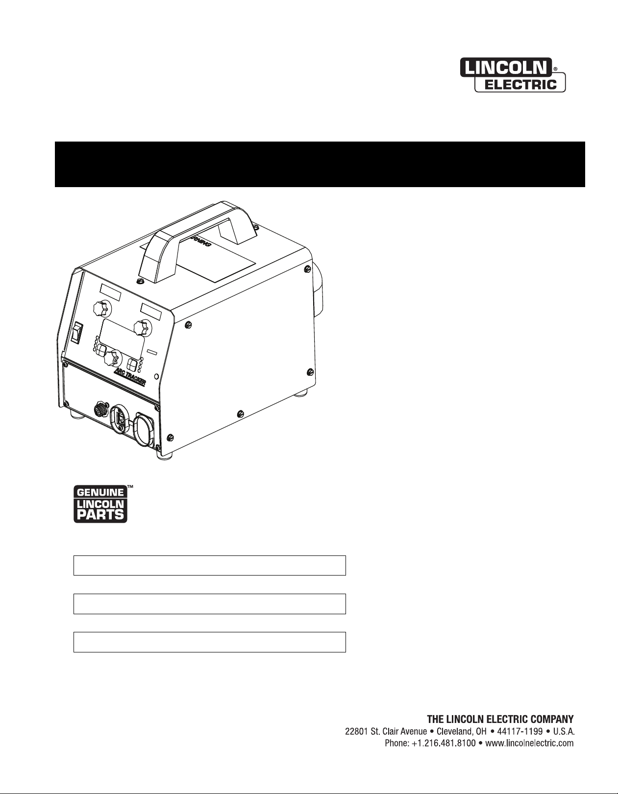
Operator’s Manual
ARC TRACKER
™
For use with machines having Code Numbers:
11742
Register your machine:
www.lincolnelectric.com/register
Authorized Service and Distributor Locator:
www.lincolnelectric.com/locator
Save for future reference
Date Purchased
Code: (ex: 10859)
Serial: (ex: U1060512345)
IM10090 | Issue D ate May-17
© Lincoln Global, Inc. All Rights Reserved.
Page 2
THANK YOU FOR SELECTING
A QUALITY PRODUCT BY
LINCOLN ELEC TRIC.
PLEASE EXAMINE CARTON AND EQUIPMENT FOR
DAMAGE IMMEDIATELY
When this equipment is shipped, title passes to the purchaser
upon receipt by the carrier. Consequently, claims for material
damaged in shipment must be made by the purchaser against the
transportation company at the time the shipment is received.
SAFETY DEPENDS ON YOU
Lincoln arc welding and cutting equipment is designed and built
with safety in mind. However, your overall safety can be increased
by proper installation ... and thoughtful operation on your part.
DO NOT INSTALL, OPERATE OR REPAIR THIS EQUIPMENT
WITHOUT READING THIS MANUAL AND THE SAFETY
PRECAUTIONS CONTAINED THROUGHOUT. And, most importantly,
think before you act and be careful.
This statement appears where the information must be followed
exactly to avoid serious personal injury or loss of life.
This statement appears where the information must be followed
to avoid minor personal injury or damage to this equipment.
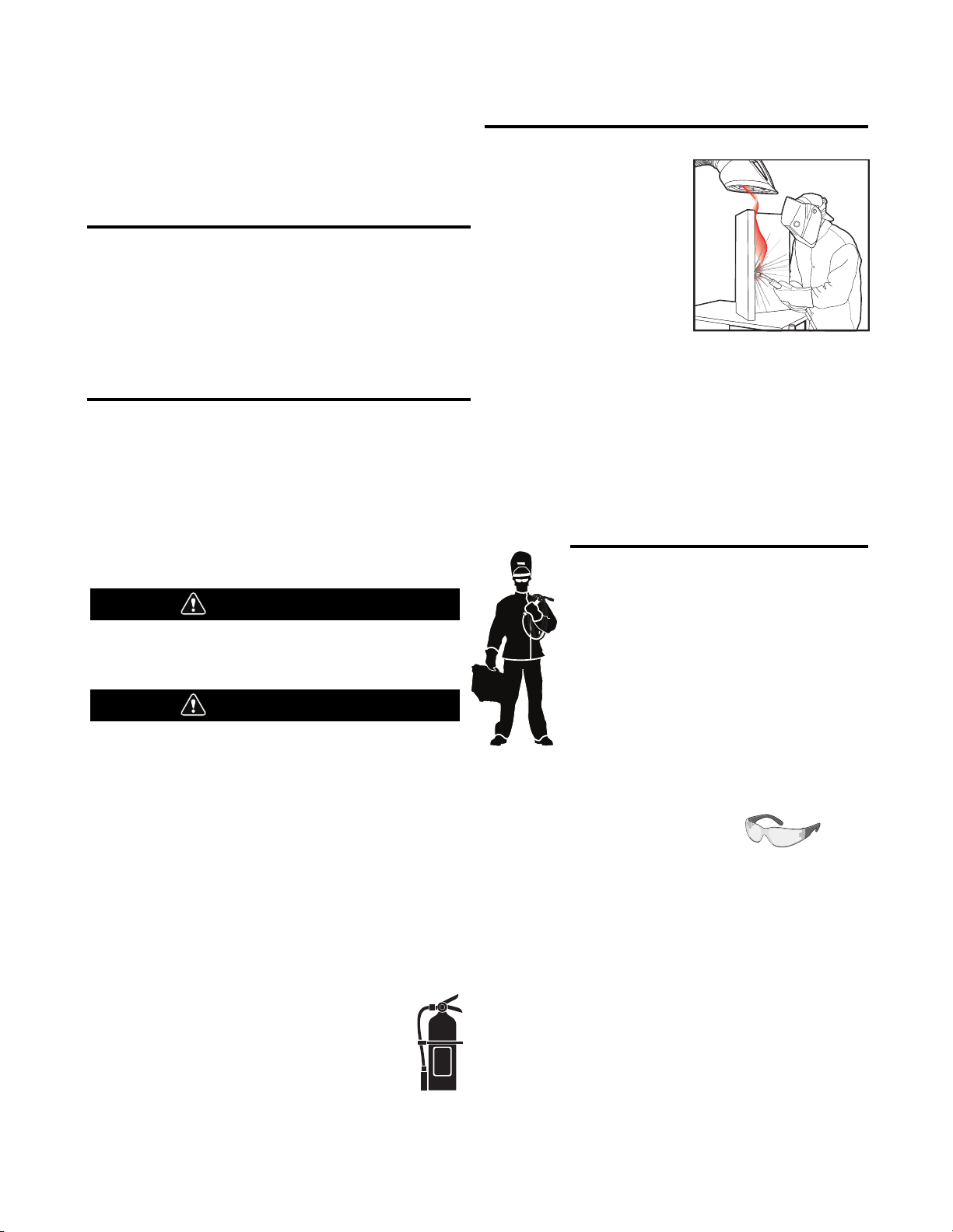
KEEP YOUR HEAD OUT OF THE FUMES.
DON’T get too close to the arc.
Use corrective lenses if necessary
to stay a reasonable distance
away from the arc.
READ and obey the Safety Data
Sheet (SDS) and the warning label
that appears on all containers of
welding materials.
USE ENOUGH VENTILATION or
exhaust at the arc, or both, to
keep the fumes and gases from
your breathing zone and the general area.
IN A LARGE ROOM OR OUTDOORS, natural ventilation may be
adequate if you keep your head out of the fumes (See below).
USE NATURAL DRAFTS or fans to keep the fumes away
from your face.
If you de velop unusual symptoms, see your supervisor.
Perhaps the welding atmosphere and ventilation system
should be checked.
WEAR CORRECT EYE, EAR &
BODY PROTECTION
PROTECT your eyes and face with welding helmet
properly fitted and with proper grade of filter plate
(See ANSI Z49.1).
PROTECT your body from welding spatter and arc
flash with protective clothing including woolen
clothing, flame-proof apron and gloves, leather
leggings, and high boots.
PROTECT others from splatter, flash, and glare
with protective screens or barriers.
IN SOME AREAS, protection from noise may be appropriate.
BE SURE protective equipment is in good condition.
Also, wear safety glasses in work area
AT ALL TIMES.
SPECIAL SITUATIONS
DO NOT WELD OR CUT containers or materials which previously
had been in contact with hazardous substances unless they are
properly cleaned. This is extremely dangerous.
DO NOT WELD OR CUT painted or plated parts unless special
precautions with ventilation have been taken. They can release
highly toxic fumes or gases.
Additional precautionary measures
PROTECT compressed gas cylinders from excessive heat,
mechanical shocks, and arcs; fasten cylinders so they cannot fall.
BE SURE cylinders are never grounded or part of an
electrical circuit.
REMOVE all potential fire hazards from welding area.
ALWAYS HAVE FIRE FIGHTING EQUIPMENT READY FOR
IMMEDIATE USE AND KNOW HOW TO USE IT.
WARNING
CAUTION
Safety 01 of 04 - 5/16/2018
Page 3
SECTION A:
WARNINGS
CALIFORNIA PROPOSITION 65 WARNINGS
WARNING: Breathing diesel engine exhaust
exposes you to chemicals known to the State
of California to cause cancer and birth defects,
or other reproductive harm.
• Always start and operate the engine in a
well-ventilated area.
• If in an exposed area, vent the exhaust to the outside.
• Do not modify or tamper with the exhaust system.
• Do not idle the engine except as necessary.
For more information go to
www.P65 warnings.ca.gov/diesel
WARNING: This product, when used for welding or
cutting, produces fumes or gases which contain
chemicals known to the State of California to cause
birth defects and, in some cases, cancer. (California
Health & Safety Code § 25249.5 et seq.)
WARNING: Cancer and Reproductive Harm
www.P65warnings.ca.gov
ARC WELDING CAN BE HAZARDOUS. PROTECT
YOURSELF AND OTHERS FROM POSSIBLE SERIOUS
INJURY OR DEATH. KEEP CHILDREN AWAY.
PACEMAKER WEARERS SHOULD CONSULT WITH
THEIR DOCTOR BEFORE OPERATING.
Read and understand the following safety highlights. For
additional safety information, it is strongly recommended
that you purchase a copy of “Safety in Welding & Cutting ANSI Standard Z49.1” from the American Welding Society,
P.O. Box 351040, Miami, Florida 33135 or CSA Standard
W117.2-1974. A Free copy of “Arc Welding Safety” booklet
E205 is available from the Lincoln Electric Company,
22801 St. Clair Avenue, Cleveland, Ohio 44117-1199.
BE SURE THAT ALL INSTALLATION, OPERATION,
MAINTENANCE AND REPAIR PROCEDURES ARE
PERFORMED ONLY BY QUALIFIED INDIVIDUALS.
FOR ENGINE POWERED
EQUIPMENT.
1.a. Turn the engine off before troubleshooting
and maintenance work unless the
maintenance work requires it to be running.
1.b. Operate engines in open, well-ventilated areas or vent the engine
exhaust fumes outdoors.
1.c. Do not add the fuel near an open flame welding
arc or when the engine is running. Stop the
engine and allow it to cool before refueling to
prevent spilled fuel from vaporizing on contact
with hot engine parts and igniting. Do not spill fuel when filling
tank. If fuel is spilled, wipe it up and do not start engine until
fumes have been eliminated.
1.d. Keep all equipment safety guards, covers
and devices in position and in good repair.
Keep hands, hair, clothing and tools away
from V-belts, gears, fans and all other
moving parts when starting, operating or
repairing equipment.
1.e. In some cases it may be necessary to remove safety guards to
perform required maintenance. Remove guards only when
necessary and replace them when the maintenance requiring
their removal is complete. Always use the greatest care when
working near moving parts.
1.f. Do not put your hands near the engine fan. Do not attempt to
override the governor or idler by pushing on the throttle control
rods while the engine is running.
1.g. To prevent accidentally starting gasoline engines while turning
the engine or welding generator during maintenance work,
disconnect the spark plug wires, distributor cap or magneto wire
as appropriate.
1.h. To avoid scalding, do not remove the radiator
pressure cap when the engine is
hot.
ELECTRIC AND
MAGNETIC FIELDS MAY
BE DANGEROUS
2.a. Electric current flowing through any conductor
causes localized Electric and Magnetic Fields (EMF).
Welding current creates EMF fields around welding cables
and welding machines
2.b. EMF fields may interfere with some pacemakers, and
welders having a pacemaker should consult their physician
before welding.
2.c. Exposure to EMF fields in welding may have other health effects
which are now not known.
2.d. All welders should use the following procedures in order to
minimize exposure to EMF fields from the welding circuit:
2.d.1. Route the electrode and work cables together - Secure
them with tape when possible.
2.d.2. Never coil the electrode lead around your body.
2.d.3. Do not place your body between the electrode and work
cables. If the electrode cable is on your right side, the
work cable should also be on your right side.
2.d.4. Connect the work cable to the workpiece as close as possible to the area being welded.
2.d.5. Do not work next to welding power source.
SAFETY
Safety 02 of 04 - 5/16/2018
Page 4
ELECTRIC SHOCK
CAN KILL.
3.a. The electrode and work (or ground) circuits are
electrically “hot” when the welder is on. Do
not touch these “hot” parts with your bare skin or wet clothing.
Wear dry, hole-free gloves to insulate hands.
3.b. Insulate yourself from work and ground using dry insulation.
Make certain the insulation is large enough to cover your full area
of physical contact with work and ground.
In addition to the normal safety precautions, if
welding must be performed under electrically
hazardous conditions (in damp locations or while
wearing wet clothing; on metal structures such as
floors, gratings or scaffolds; when in cramped
positions such as sitting, kneeling or lying, if there
is a high risk of unavoidable or accidental contact
with the workpiece or ground) use the following
equipment:
• Semiautomatic DC Constant Voltage (Wire) Welder.
• DC Manual (Stick) Welder.
• AC Welder with Reduced Voltage Control.
3.c. In semiautomatic or automatic wire welding, the electrode,
electrode reel, welding head, nozzle or semiautomatic welding
gun are also electrically “hot”.
3.d. Always be sure the work cable makes a good electrical
connection with the metal being welded. The connection should
be as close as possible to the area being welded.
3.e. Ground the work or metal to be welded to a good electrical (earth)
ground.
3.f. Maintain the electrode holder, work clamp, welding cable and
welding machine in good, safe operating condition. Replace
damaged insulation.
3.g. Never dip the electrode in water for cooling.
3.h. Never simultaneously touch electrically “hot” parts of electrode
holders connected to two welders because voltage
between the
two can be the total of the open circuit voltage of both
welders.
3.i. When working above floor level, use a safety belt to protect
yourself from a fall should you get a shock.
3.j. Also see It ems 6.c. and 8.
ARC RAYS CAN BURN.
4.a. Use a shield with the proper filter and cover plates to protect your
eyes from sparks and the rays of the arc when welding or
observing open arc welding. Headshield and filter lens should
conform to ANSI Z87. I standards.
4.b. Use suitable clothing made from durable flame-resistant material
to protect your skin and that of your helpers from the arc rays.
4.c. Protect other nearby personnel with suitable, non-flammable
screening and/or warn them not to watch the arc nor expose
themselves to the arc rays or to hot spatter or metal.
FUMES AND GASES
CAN BE DANGEROUS.
5.a. Welding may produce fumes and gases
hazardous to health. Avoid breathing these
fumes and gases. When welding, keep your head out of the fume.
Use enough ventilation and/or exhaust at the arc to keep fumes
and gases away from the breathing zone. When welding
hardfacing (see instructions on container or SDS)
or on lead or cadmium plated steel and other
metals or coatings which produce highly toxic
fumes, keep exposure as low as possible and
within applicable OSHA PEL and ACGIH TLV limits
using local exhaust or mechanical ventilation
unless exposure assessments indicate otherwise.
In confined spaces or in some circumstances,
outdoors, a respirator may also be required.
Additional precautions are also required when
welding
on galvanized steel.
5. b. The operation of welding fume control equipment is affected by
various factors including proper use and positioning of the
equipment, maintenance of the equipment and the specific
welding procedure and application involved. Worker exposure
level should be checked upon installation and periodically
thereafter to be certain it is within applicable OSHA PEL and
ACGIH TLV limits.
5.c. Do not weld in locations near chlorinated hydrocarbon vapors
coming from degreasing, cleaning or spraying operations. The
heat and rays of the arc can react with solvent vapors to form
phosgene, a highly toxic gas, and other irritating products.
5.d. Shielding gases used for arc welding can displace air and
cause
injury or death. Always use enough ventilation, especially in
confined areas, to insure breathing air is safe.
5.e. Read and understand the manufacturer’s instructions for this
equipment and the consumables to be used, including the
Safety Data Sheet (SDS) and follow your employer’s safety
practices. SDS forms are available from your welding
distributor or from the manufacturer.
5.f. Also see item 1.b.
SAFETY
Safety 03 of 04 - 5/16/2018
Page 5
WELDING AND CUTTING
SPARKS CAN CAUSE
FIRE OR EXPLOSION.
6.a. Remove fire hazards from the welding area. If
this is not possible, cover them to prevent the welding sparks
from starting a fire. Remember that welding sparks and hot
materials from welding can easily go through small cracks and
openings to adjacent areas. Avoid welding near hydraulic lines.
Have a fire extinguisher readily available.
6.b. Where compressed gases are to be used at the job site, special
precautions should be used to prevent hazardous situations.
Refer to “Safety in Welding and Cutting” (ANSI Standard Z49.1)
and the operating information for the equipment being used.
6.c. When not welding, make certain no part of the electrode circuit is
touching the work or ground. Accidental contact can cause
overheating and create a fire hazard.
6.d. Do not heat, cut or weld tanks, drums or containers until the
proper steps have been taken to insure that such procedures
will not cause flammable or toxic vapors from substances inside.
They can cause an explosion even though they have been
“cleaned”. For information, purchase “Recommended Safe
Practices for the Preparation for Welding and Cutting of
Containers and Piping That Have Held Hazardous Substances”,
AWS F4.1 from the American Welding Society
(see address above).
6.e. Vent hollow castings or containers before heating, cutting or
welding. They may explode.
6.f. Sparks and spatter are thrown from the welding arc. Wear oil free
protective garments such as leather gloves, heavy shirt, cuffless
trousers, high shoes and a cap over your hair. Wear ear plugs
when welding out of position or in confined places. Always wear
safety glasses with side shields when in a welding area.
6.g. Connect the work cable to the work as close to the welding area
as practical. Work cables connected to the building framework or
other locations away from the welding area increase the
possibility of the welding current passing through lifting chains,
crane cables or other alternate circuits. This can create fire
hazards or overheat lifting chains or cables until they fail.
6.h. Also see item 1.c.
6.I. Read and follow NFPA 51B “Standard for Fire Prevention During
Welding, Cutting and Other Hot Work”, available from NFPA, 1
Batterymarch Park, PO box 9101, Quincy, MA 022690-9101.
6.j. Do not use a welding power source for pipe thawing.
CYLINDER MAY EXPLODE IF
DAMAGED.
7.a. Use only compressed gas cylinders containing
the correct shielding gas for the process used
and properly operating regulators designed for
the gas and pressure used. All hoses, fittings,
etc. should be suitable for the application and
maintained in good condition.
7.b. Always keep cylinders in an upright position securely chained to
an undercarriage or fixed support.
7.c. Cylinders should be located:
• Away from areas where they may be struck or subjected
to physical damage.
• A safe distance from arc welding or cutting operations
and any other source of heat, sparks, or flame.
7.d. Never allow the electrode, electrode holder or any other
electrically “hot” parts to touch a cylinder.
7.e. Keep your head and face away from the cylinder valve outlet
when opening the cylinder valve.
7.f. Valve protection caps should always be in place and hand tight
except when the cylinder is in use or connected for use.
7.g. Read and follow the instructions on compressed gas cylinders,
associated equipment, and CGA publication P-l, “Precautions for
Safe Handling of Compressed Gases in Cylinders,” available from
the Compressed Gas Association, 14501 George Carter Way
Chantilly, VA 20151.
FOR ELECTRICALLY
POWERED EQUIPMENT.
8.a. Turn off input power using the disconnect
switch at the fuse box before working on
the equipment.
8.b. Install equipment in accordance with the U.S. National Electrical
Code, all local codes and the manufacturer’s recommendations.
8.c. Ground the equipment in accordance with the U.S. National
Electrical Code and the manufacturer’s recommendations.
Refer to
http://www.lincolnelectric.com/safety
for additional safety information.
SAFETY
Safety 04 of 04 - 5/16/2018
Page 6

v
SAFETY
Electromagnetic Compatibility (EMC)
Conformance
Products displaying the CE mark are in conformity with European Community Council Directive of 15 Dec
004 on the approximation of the laws of the Member States relating to electromagnetic compatibility,
2
2004/108/EC. It was manufactured in conformity with a national standard that implements a harmonized
tandard: EN 60974-10 Electromagnetic Compatibility (EMC) Product Standard for Arc Welding Equipment.
s
It is for use with other Lincoln Electric equipment. It is designed for industrial and professional use.
Introduction
All electrical equipment generates small amounts of electromagnetic emission. Electrical emission may be
transmitted through power lines or radiated through space, similar to a radio transmitter. When emissions
are received by other equipment, electrical interference may result. Electrical emissions may affect many
kinds of electrical equipment; other nearby welding equipment, radio and TV reception, numerical controlled
machines, telephone systems, computers, etc. Be aware that interference may result and extra precautions
may be required when a welding power source is used in a domestic establishment.
Installation and Use
The user is responsible for installing and using the welding equipment according to the manufacturer’s
instructions. If electromagnetic disturbances are detected then it shall be the responsibility of the user of the
welding equipment to resolve the situation with the technical assistance of the manufacturer. In some cases
this remedial action may be as simple as earthing (grounding) the welding circuit, see Note. In other cases it
could involve construction of an electromagnetic screen enclosing the power source and the work complete
with associated input filters. In all cases electromagnetic disturbances must be reduced to the point where
they are no longer troublesome.
v
Note: The welding circuit may or may not be earthed for safety reasons according to national
codes. Changing the earthing arrangements should only be authorized by a person who is
competent to access whether the changes will increase the risk of injury, e.g., by allowing
parallel welding current return paths which may damage the earth circuits of other equipment.
Assessment of Area
Before installing welding equipment the user shall make an assessment of potential electromagnetic problems in the surrounding area. The following shall be taken into account:
a) other supply cables, control cables, signaling and telephone cables; above, below and adjacent to the
welding equipment;
b) radio and television transmitters and receivers;
c) computer and other control equipment;
d) safety critical equipment, e.g., guarding of industrial equipment;
e) the health of the people around, e.g., the use of pacemakers and hearing aids;
f) equipment used for calibration or measurement
g) the immunity of other equipment in the environment. The user shall ensure that other equipment being
used in the environment is compatible. This may require additional protection measures;
h) the time of day that welding or other activities are to be carried out.
Page 7

vi
SAFETY
Electromagnetic Compatibility (EMC)
The size of the surrounding area to be considered will depend on the structure of the building and other
activities that are taking place. The surrounding area may extend beyond the boundaries of the premises.
Methods of Reducing Emissions
Mains Supply
Welding equipment should be connected to the mains supply according to the manufacturer’s recommendations. If interference occurs, it may be necessary to take additional precautions such as filtering of the mains
supply. Consideration should be given to shielding the supply cable of permanently installed welding equipment, in metallic conduit or equivalent. Shielding should be electrically continuous throughout its length. The
shielding should be connected to the welding power source so that good electrical contact is maintained
between the conduit and the welding power source enclosure.
Maintenance of the Welding Equipment
The welding equipment should be routinely maintained according to the manufacturer’s recommendations.
All access and service doors and covers should be closed and properly fastened when the welding equipment is in operation. The welding equipment should not be modified in any way except for those changes
and adjustments covered in the manufacturers instructions. In particular, the spark gaps of arc striking and
stabilizing devices should be adjusted and maintained according to the manufacturer’s recommendations.
vi
Welding Cables
The welding cables should be kept as short as possible and should be positioned close together, running at
or close to floor level.
Equipotential Bonding
Bonding of all metallic components in the welding installation and adjacent to it should be considered.
However, metallic components bonded to the work piece will increase the risk that the operator could
receive a shock by touching these metallic components and the electrode at the same time. The operator
should be insulated from all such bonded metallic components.
Earthing of the Workpiece
Where the workpiece is not bonded to earth for electrical safety, not connected to earth because of its size
and position, e.g., ships hull or building steelwork, a connection bonding the workpiece to earth may reduce
emissions in some, but not all instances. Care should be taken to prevent the earthing of the workpiece
increasing the risk of injury to users, or damage to other electrical equipment. Where necessary, the connection of the workpiece to earth should be made by a direct connection to the workpiece, but in some countries
where direct connection is not permitted, the bonding should be achieved by suitable capacitance, selected
according to national regulations.
Screening and Shielding
Selective screening and shielding of other cables and equipment in the surrounding area may alleviate problems of interference. Screening of the entire welding installation may be considered for special
applications
_________________________
1.
1
Portions of the preceding text are contained in EN 60974-10: “Electromagnetic Compatibility (EMC) product standard for arc welding equipment.”
Page 8

viii viii
Page
Installation....................................................................................................... Section A
Technical Specifications........................................................................................ A-1
Safety Precautions.......................................................................................... A-2
Select Suitable Location..................................................................................A-2
Lifting...............................................................................................................A-2
Stacking.......................................................................................................... A-2
Environmental Limitations............................................................................... A-2
Input and Grounding Connections.................................................................. A-2
High Frequency Protection.................................................................................... A-2
Recommended Electrode and Work Cable for arc Welding.................................. A-2
Electrical Connection...................................................................................... A-3
Work Connection.............................................................................................A-3
Remote Sense Lead Specification.................................................................. A-3
Product Specific Instructions........................................................................... A-3
Software Tools................................................................................................ A-3
Power Wave Manager.....................................................................................A-3
Connection Diagram-Electrode Positive................................................................ A-4
________________________________________________________________________
Operation......................................................................................................... Section B
Safety Precautions.................................................................................................B-1
Graphic Symbols............................................................................................B-1, B-2
Product Description............................................................................................... B-2
Design Features.................................................................................................... B-2
Recommended Processes and Equipment........................................................... B-3
Common Equipment Packages............................................................................. B-3
Case Front Description.......................................................................................... B-4
Case Back Controls............................................................................................... B-5
Power-Up Sequence..............................................................................................B-5
Duty Cycle............................................................................................................. B-5
Common Welding Procedures...............................................................................B-5
Set-Up Feature Menu............................................................................................ B-6
_______________________________________________________________________
TABLE OF CONTENTS
Maintenance.................................................................................................... Section D
Safety Precautions................................................................................................ D-1
Routine Maintenance............................................................................................ D-1
Periodic Maintenance............................................................................................ D-1
Calibration Specification........................................................................................ D-1
Calibration Procedure..............................................................................D-2 thru D-3
________________________________________________________________________
Section E.............................................................................................. Troubleshooting
Safety Precautions.................................................................................................E-1
How to Use Troubleshooting Guide.......................................................................E-1
Troubleshooting Guide.......................................................................................... E-2
________________________________________________________________________
Wiring Diagram and Dimension Print.............................................................. Section F
________________________________________________________________________
Parts List.................................................................................................... P-675 Series
________________________________________________________________________
Page 9
A-1
INSTALLATION
A-1
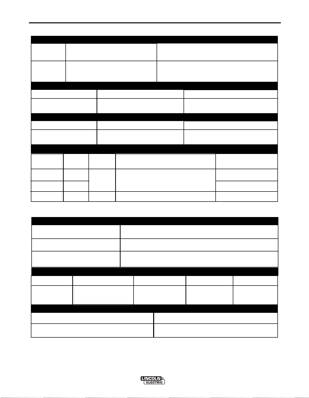
TECHNICAL SPECIFICATIONS -
INPUT VOLTAGE AND CURRENT
odel
M
K3019-1
Duty Cycle
Duty Cycle
VOLTAGE
50/60 Hz
100%
100%
Input
Amperes
Input Voltage ± 10%
120-230 V AC, 50/60 Hz
RATED OPERATING RANGE NEMA EW1
Volts at Rated Amperes
RATED OPERATING RANGE IEC60974-1
Volts at Rated Amperes
RECOMMENDED INPUT WIRE
REGION
ARC TRACKER™
44 V DC
44 V DC
INPUT CORD
Input Amperes
0.8-0.5 A
Amperes
1000 A DC
Amperes
1000 A DC
PLUG
120
230
230
* All attachment plugs must comply with the Standard for Attachment Plugs and Receptacles, UL498.
0.8 A
0.5 A
0.5 A
NORTH
AMERICA
EUROPE
3 CONDUCTOR, #18 AWG
TYPE S, SO, SOO, ST, STO, STOO OR
EQUIVALENT EXTRA HARD USAGE CORD
3 CONDUCTOR, 1.0 mm2HAR
NEMA 5-15P (INCLUDED)
ANY NEMA 250 V TYPE*
CEE 7/7
METER ACCURACY (AS SHIPPED)
VOLTMETER
AMMETER
ENERGY
± 2% + 0.1**
± 2% + 2**
± 5%
PHYSICAL DIMENSIONS
MODEL
K3019-1
HEIGHT
12 in (305 mm)
WIDTH
9 in (220 mm)
DEPTH
15 in (380 mm)
TEMPERATURE RANGES
WEIGHT
20 lbs ( 9 kg)
OPERATING TEMPERATURE RANGE
STORAGE TEMPERATURE RANGE
**Accuracy is expressed as +/- [Percentage of Reading + Digits].
For example: 10A = +/- 10A x 0.02 + 2 = 10A +/- 2.2, or 7.8A to 12.2A
ARC TRACKER™
14°F TO 104°F (-10°C TO 40°C)
-40°F TO 185°F (-40°C TO 85°C)
Page 10

A-2
INSTALLATION
A-2
SAFETY PRECAUTIONS
WARNING
LECTRIC SHOCK can kill.
E
• ONLY Q U AL IF I ED PER S ON NE L
HOULD PERFORM THIS INSTAL-
S
LATION.
• TURN OFF INPUT POWER TO THE
POWE R SO UR C E A T T HE D IS CO N NE CT
WITCH OR FUSE BOX BEFORE WORKING ON
S
THIS EQUI P M E N T . T URN OFF THE INPUT
POWER TO ANY OTHER EQUIPMENT CONNECTED TO THE WELDING SYSTEM AT THE
DISCONNECT SWITCH OR FUSE BOX BEFORE
WORKING ON THE EQUIPMENT.
• DO NOT TOUCH ELECTRICALLY HOT PARTS.
• CONNECT THE ARC TRACKER™ TO AN OUTLET W IT H PROPE R SAFET Y (EART H )
GROUND.
----------------------------------------------------------------------
SELECT SUITABLE LOCATION
UNIT IS IP23 RATED.
The ARC TRACKER™ will operate in harsh environments. Even so, it is important that simple preventative
measures are followed in order to assure long life and
reliable operation.
• Keep machine dry. Shelter from rain and snow. Do
not place on wet ground or in puddles.
TILTING
and the information in this manual.
The ARC TRACKER™ can be connected to 120 V AC
or 230 V AC, 50 or 60 Hz. The power supply inside
the unit can accept any single phase input voltage
rom 120 V AC to 230 V AC. The unit is shipped from
f
the factory with a 6ft. (2m) detachable input cord with
a NEMA 5-15P plug and an IEC 60320 plug receptacle. For the European market, it is suggested that an
input cord with a CEE 7/ 7 plug and IEC 60320 plug
receptacle be used. For all other regions, a cord
should be used with a plug which provides between
120 V AC and 230 V AC, 50 or 60Hz, and has the IEC
60320 plug receptacle. Cord must provide proper
ground per national electrical codes.
230 V INPUT
To change from 120 V to 230 V single phase input,
the NEMA 5-15P plug can be replaced by any NEMA
250 V type plug (for example – type 6-30P).
ATTACHMENT PLUG
In all cases, the green or green/yellow grounding wire
must be connected to the grounding pin of the plug,
usually identified by a green screw. All attachment
plugs must comply with the Standard for Attachment
Plugs and Receptacles, UL498. The product is considered acceptable for use only when an attachment
plug as specified is properly attached to the supply
cord. The ARC TRACKER™ will auto reconnect to
either 120 V or 230 V supplies.
Place the ARC TRACKER™ on a secure, level surface. The weight of the welding cables hanging from
the connection terminals may cause the ARC TRACKER™ to topple. Secure the welding cables to an
appropriate structure to reduce the hanging weight to
stabilize the ARC TRACKER™
STACKING
The ARC TRACKER™ cannot be stacked.
GROUNDING AND INPUT CONNECTIONS
MACHINE GROUNDING
The frame of the ARC TRACKER™ must be
grounded. By using the power cord shipped
with the unit, or by using a cord per the specifications described here, the unit will be properly
grounded if connected to a grounded receptacle. See
your local and national electrical codes for proper
receptacle grounding methods.
INPUT CONNECTIONS
Installation should be made in accordance with the
appropriate National Electrical Code, all local codes
HIGH FREQUENCY PROTECTION
The EMC classification of the ARC TRACKER™ is
Industrial, Scientific and Medical (ISM) group 2, class
A. The ARC TRACKER™ is for industrial use only.
(See Electromagnetic Compatibility EMC Safety
Section).
Harmonic Current Information:
Design complies with EN6100-3-2, -3.
Locate the ARC TRACKER™ away from radio controlled machinery. The normal operation of the ARC
TRACKER™ may adversely affect the operation of RF
controlled equipment, which may result in bodily injury
or damage to the equipment.
REC OMM END ED ELE CTR ODE AND
WORK CABLE SIZES FOR ARC WELDING
General Guidelines
The following recommendations apply to all output
polarities and weld modes:
ARC TRACKER™
Page 11

A-3
• Select the appropriate size cables per the "Output
Cable Guidelines" Table A.1. Excessive voltage
drops caused by undersized welding cables and
poor connections often result in unsatisfactory welding performance. Always use the largest welding
ables (electrode and work) that are practical, and
c
be sure all connections are clean and tight.
Note: Excessive heat in the weld circuit indicates
undersized cables and/or bad connections.
• Route all cables directly to the work and electrode,
avoid excessive lengths and do not coil excess
cable. Route the electrode and work cables in close
proximity to one another to minimize the loop area
and therefore the inductance of the weld circuit.
• Always weld in a direction away from the work con-
INSTALLATION
A-3
REMOTE SENSE LEAD SPECIFICATIONS
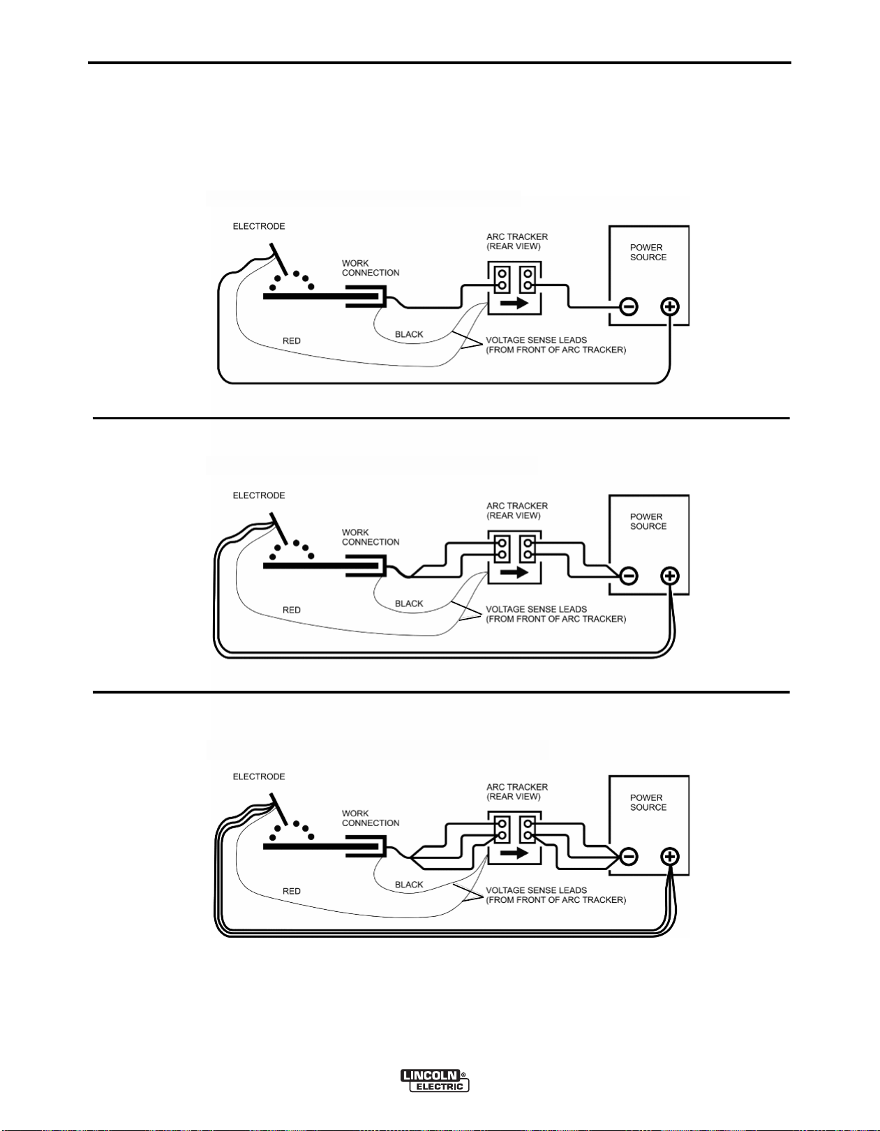
(See Figure A.1)
In order to get an accurate measurement of the true
energy going in to the weld, it is critical to get an
accurate measurement of the arc voltage. The arc
oltage sense leads are polarity specific – RED must
v
be connected to the positive side of the arc and
BLACK to the negative. The sense leads should be
connected as close as possible to the arc, e.g. at the
contact tip, wire feeder, etc and to the work.
PRODUCT SPECIFIC INSTRUCTIONS
Best Practices
Place the ARC TRACKER™ in the work circuit. This
will keep the ARC TRACKER™ at the same potential
as the work piece.
:
ELECTRODE CONNECTIONS
Electrode Positive (See Figure A.1)
Connect cable(s) of sufficient size and length (Per
Table A.1) to the "ELECTRODE" terminals on the
power source. Connect the other end of the electrode
cable(s) to the contact tip, wire feeder, etc. Be sure
the connection makes tight metal-to-metal electrical
contact.
WORK CONNECTIONS
Electrode Positive (See Figure A.1)
Connect cable(s) of sufficient size and length (Per
Table A.1) between the "WORK" terminals on the
power source and the ARC TRACKER™ right side
weld terminals (when viewed from the rear). Connect
cable(s) of sufficient size and length from the ARC
TRACKER™ left weld terminals to the work. Be sure
the connection to the work makes tight metal-to-metal
electrical contact.
The welding current MUST flow into the left side weld
terminals (when viewing the ARC TRACKER™ from
the rear) and out of the right side weld terminals. If the
we l ding cu r r ent doe s not flow through the ARC
TRACKER™ in the right direction, the unit will not
properly sense the welding current and nothing will be
displayed on the unit during welding.
See the specific power source instruction manual for
additional general guidelines on output cable connections.
SOFTWARE TOOLS
ARC TRACKER™ software tools and other documents related to the integration, configuration, and
operation of the system are available at,
www.powerwavesoftware.com
An Ethernet connection gives the ARC TRACKER™
the a bi li t y to ru n Po w er Wa ve Ma na ge r and
Production Monitoring™.
Power Wave Manager
Total Cable Length ft (m)
Electrode and Work Combined
0 (0) to 250 (76.2)
• Ethernet setup and verification
• Calibration
• Production Monitoring Configuration
• User Interface Lockout
TABLE A.1 Output Cable Guidelines
Current in Weld
Circuit
0-500 Amps
500-750 Amps
750-1000 Amps
Duty Cycle
(parallel if more than one)
100%
ARC TRACKER™
Number of Cables
1
2
3
Cable Size
(copper) AWG
4/0 (120 mm2)
4/0 (120 mm2)
3/0 (95 mm2)
Page 12
A-4
CONNECTION DIAGRAM-ELECTRODE POSITIVE (750-1000A)
CONNECTION DIAGRAM-ELECTRODE POSITIVE (0-500A)
CONNECTION DIAGRAM-ELECTRODE POSITIVE (500-750A)
INSTALLATION
FIGURE A.1
A-4
ARC TRACKER™
Page 13

B-1
OPERATION
B-1
SAFETY PRECAUTIONS
Read this entire section of operating instructions
before operating the machine.
WARNING
ELECTRIC SHOCK can kill.
• Unless using cold feed feature, when
feed i ng with gu n tr ig ge r , th e
electrode and drive mechanism are
al ways electricall y ene r gized and
coul d re ma in e ne rg i ze d s ev e ra l
seconds after the welding ceases.
• Do not touch electrically live parts or electrodes
with your skin or wet clothing.
• Insulate yourself from the work and ground.
• Always wear dry insulating gloves.
FUMES AND GASES can be
dangerous.
• Keep your head out of fumes.
GR APHIC SYMBOLS THAT
APPEAR ON THIS MACHINE
OR IN THIS MANUAL
MACHINE STATUS
ON
OFF
ELECTRODE
READ INSTRUCTION
MANUAL
PROPER DISPOSAL
• Use ventilation or exhaust to remove
fumes from breathing zone.
WELDING SPARKS can cause
fire or explosion.
• Keep flammable material away.
• Do not weld on containers that have
held combustibles.
ARC RAYS can burn.
• Wear eye, ear, and body protection.
Observe additional guidelines detailed in the
beginning of this manual.
IP23
CAL
RANGE
POSITIVE OUTPUT
NEGATIVE OUTPUT
ENCLOSURE RATING
INPUT POWER
CALIBRATION
WELD CURRENT
ARC TRACKER™
X
DUTY CYCLE
WORK CONNECTION
Page 14

B-2
OPERATION
B-2
GR APHIC SYMBOLS THAT
APPEAR ON THIS MACHINE
OR IN THIS MANUAL
WELD AMPERAGE
INPUT VOLTAGE
WELD VOLTAGE
INPUT CURRENT
OUTPUT CURRENT
PROTECTIVE
GROUND
U
A
V
I
1
I
2
1
PRODUCT DESCRIPTION
General Functional Description
The AR C TR AC KE R ™ is a hi gh - pe rf o rm an c e,
portable product designed to accurately measure the
True Energy delivered into a weld from any welding
machine (DC process only). The ARC TRACKER™
will accurately measure the welding parameters (arc
voltage, arc current, and weld time) and provide a
real-time calculation of the True Energy into the weld.
While welding, the True Energy [in joules (J)] for the
weld will be accurately displayed on the user interface.
The ARC TRACKER™ utilizes high-intensity LEDs
and alpha-numeric displays that can easily be seen
from a distance. The design uses advanced digital
controls to sample the welding parameters at a very
high rate of speed. The ARC TRACKER™ is compatible with any DC welding process.
The ARC TRACKER™ has an Ethernet connector to
easily connect the product into a local network which
enables the use of Lincoln’s additional software tools.
WARNING or CAUTION
Explosion
Dangerous Voltage
Shock Hazard
SET UP MENU
ETHERNET
CONNECTOR
DESIGN FEATURES
• Multiple process DC welding range: 10-1000 Amps,
100% duty cycle.
• Simple Plug-N-Play design – connect to welding circuit, attach voltage se nse leads and the meter
begins to function!
• Digital controls for highly accurate measurements.
ARC TRACKER™
Page 15

B-3
OPERATION
RECOMMENDED PROCESSES AND
EQUIPMENT
RECOMMENDED PROCESSES
• DC arc welding circuits only
• Any welding process
• Any welding equipment
PROCESS LIMITATIONS
• Cannot be used with AC arc welding circuits
• 1000 A, 120 V, (maximum)
• Not Recommended for HF TIG applications
EQUIPMENT LIMITATIONS
• The weld terminals on the back of the ARC TRACKER™ have a maximum threshold of welding current
which can flow through them. The correct number
and size of welding conductors must be used for
proper cooling. See the installation section for proper connectivity.
B-3
• The ARC TRACKER™ has been calibrated before
being shipped from the factory. The Lincoln Electric
Company recommends that end-users of its welding
equipment evaluate the suitability of utilizing this
product in their quality system, determine if periodic
calibration is required and the calibration interval
based upon the criticality of the welding application,
the environment in which the equipment is located,
the level of preventive maintenance and the actual
conditions of use.
• The Ethernet connection gives the ARC TRACKER™ the ability to run Production Monitoring™ with
certain function limitations, such as, no support for
wire feed speed, deposition rate, consumable package tracking and weldscore.
ARC TRACKER™
Page 16
B-4
1
2
3
4
5
6
7
8
9
10
11
12
13
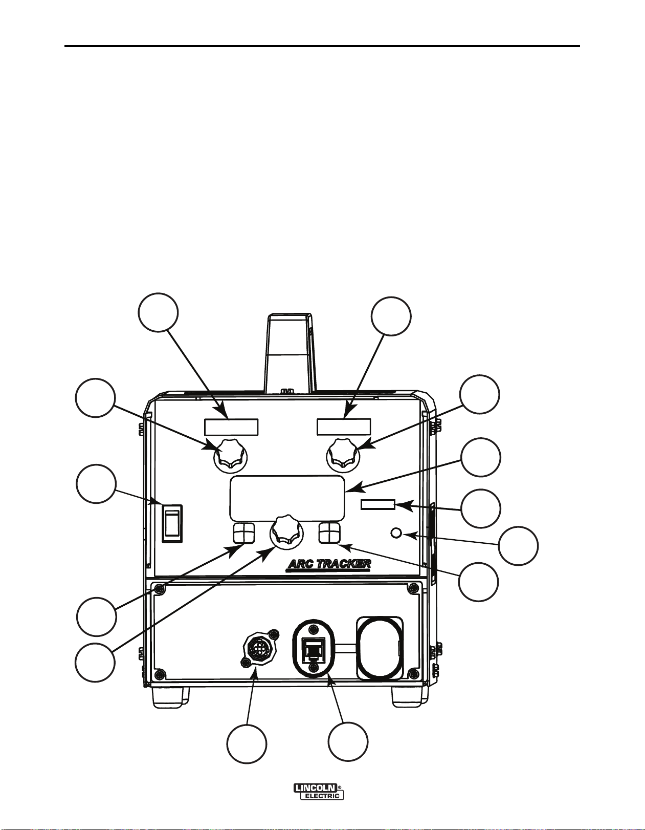
CASE FRONT CONTROL DESCRIPTIONS
(See Figure B.1)
OPERATION
8. Right Push button
B-4
. Amps Display
1
2. Volts Display
3. Amps Calibration Knob
4. Volts Calibration Knob
5. Message Display
6. Setup Mode LED
7. Left Push Button
9. Center Knob
0. ON/OFF Switch
1
11. Status LED
12. Ethernet Connector
13. Voltage Sense Lead Connector
FIGURE B.1
ARC TRACKER™
Page 17
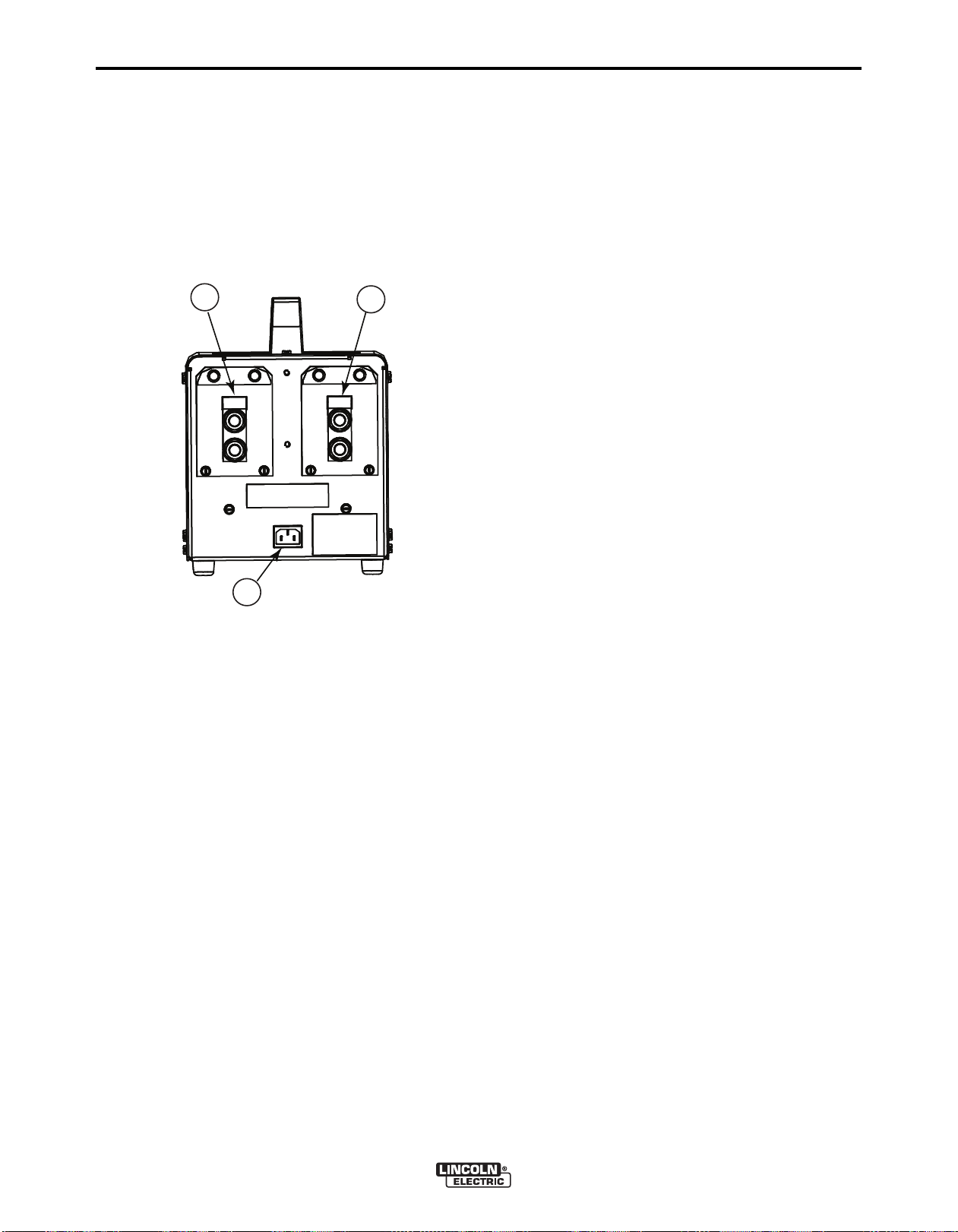
B-5
1
2
3
CASE BACK
(TERMINAL COVERS NOT SHOWN)
Case Back Descriptions (See Figure B.2)
1. Left weld terminals (weld current IN)
2. Right weld terminals (weld current OUT)
3. Input cord receptacle
FIGURE B.2
OPERATION
B-5
POWER-UP SEQUENCE
When power is applied to the ARC TRACKER™, the
status light will flash green for up to 60 seconds.
During this time the unit is performing a self test. The
status light will also flash green as a result of a system
reset or configuration change during operation. When
the status light becomes steady green the system is
ready for use.
If the status light does not become steady green consult the troubleshooting section of this manual for further instruction.
DUTY CYCLE
The
ARC TRACKER™
100% duty cycle.
• Note: The correct number and size of welding conductors must be used for proper cooling. See
the installation section for proper connectivity.
is rated for 1000 A, 44 V DC,
COMMON WELDING PROCEDURES
The ARC TRACKER™ can be used with any DC
welding process.
ARC TRACKER™
Page 18

B-6
OPERATION
SETUP MENU FEATURES
B-6
The Setu p Me n u giv e s acce ss to the Setu p
onfiguration. Stored in the setup configuration are
C
user parameters that generally only need to be set at
installation. The parameters are grouped as shown in
the following table.
1. To access the set-up menu, press the Right and
PARAMETER DEFINITION
P.1 through P.99
P.101 through P.199
P.501 through P.599
Parameter Definition
Exit Setup Menu
P.0
This option is used to exit the setup menu. When P.0 is displayed, press the Left Button to exit
the setup menu.
Unsecured Parameters
(always adjustable)
Diagnostic Parameters
(always read only)
Secured Parameters
(only accessible through a p.c.
application)
USER DEFINED PARAMETERS
2. After changing a parameter it is necessary to press
3. To exit the set-up menu at any time, press the
SET-UP FEATURES MENU
(See Figure B.1)
eft buttons of the Main Display panel simultane-
L
ously. No t e that the set-u p menu ca n not be
accessed if there is a fault (The status LED is not
solid green).
Change the value of the blinking parameter by rotating the Center knob.
the Right hand button to save the new setting.
Pressing the Left button will cancel the change.
Right and Left buttons of the Main Display panel
simultaneously. Alternately, 1 minute of inactivity
will also exit the set-up menu.
P.83 Calibration
See Calibration Specification section for further details.
P.106 View Ethernet IP Address
Used for viewing the IP address of Ethernet compatible equipment. Press the Right Button to
read the IP Address. Press the Left Button to back out and exit this option. The IP address
cannot be changed using this option.
P.505 Setup Menu Lock
Determines if the setup parameters can be modified by the operator without entering a passcode.
No = The operator can change any set menu parameter without first entering the passcode
even if the passcode is non-zero (default).
Yes = The operator must enter the passcode (if the passcode is non-zero) in order to change
any setup menu parameters.
This parameter can only be accessed using Power Wave Manager software.
P.506 Set User Interface Passcode
Prevents unauthorized changes to the equipment. The default passcode is zero which allows
full access. A nonzero passcode will prevent unauthorized changes to setup parameters (if
P.505 = Yes).
This parameter can only be accessed using Power Wave Manager software.
P.509 UI Master Lockout
Locks all user interface controls, preventing the operator from making any changes. This parameter can only be accessed using Power Wave Manager software.
ARC TRACKER™
Page 19
D
-1
MAINTENANCE
D
-1
SAFETY PRECAUTIONS
WARNING
ELECTRIC SHOCK can kill.
Only Qualifie d per s o nnel shou l d
•
perform this maintenance.
• Turn the input power OFF at th e
disconnect switch or fuse box before
orking on this equipment.
w
• Do not touch electrically hot parts.
------------------------------------------------------------------------
See ad dit iona l w arn ing inf orm ation
throughout this Operator’s Manual
------------------------------------------------------------
CALIBRATION SPECIFICATION
The ARC TRACKER™ as shipped from the factory
has +/-2% accuracy on the digital volts display and
amps display. Due to the heat input calculation being
a function of measured volts, amps, and arc on-time,
the displayed energy value has an accuracy of +/-5%.
The Lincoln Electric Company recommends that endusers of its welding equipment evaluate the suitability
of utilizing the ARC TRACKER™ in their quality system.
Required equipment:
• Power source to provide welding current and voltage. The power source should be capable of producing the same level of welding current and volt-
ge as the ARC TRACKER™ application. It is rec-
a
ommended to use the same power source used in
the welding application for this calibration procedure.
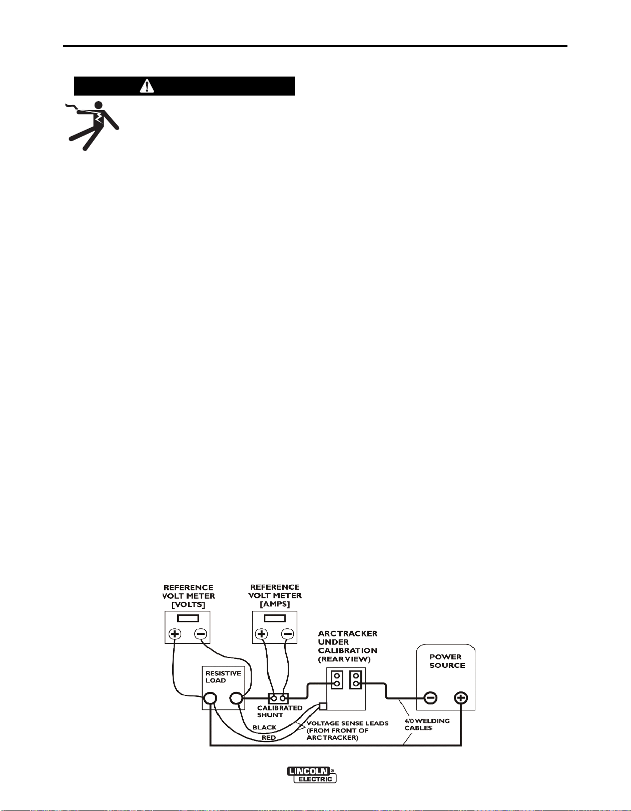
• Calibrated reference volt meter, shunt and ammeter as in Figure D.1. The recommended accuracy
must be at least four times the desired accuracy of
the digital meters on the ARC TRACKER™ being
calibrated. Example, to obtain +/-2% accuracy, the
shunt accuracy and ammeter accuracy combination must be +/-0.5% accurate. The meters listed
below have been verified to produce accurate
re sults with inverter power sour ces. I f oth er
meters are used, the compatibility and accuracy
with inverter power sources must be determined
by the user.
Volt meter: Keithley 2701 Digital Multimeter
Ammeter: Keithley 2701 Digital Multimeter
Shunt: GE 1000A/100mV Master Shunt
• Resistive Load, such as Lincoln Electric Master
Load 750 (750 A max).
Determine if periodic calibration is required and the
calibration interval based upon the criticality of the
welding application, the environment in which the
equipment is located, the level of preventive maintenance and the actual conditions of use.
FIGURE D.1
• ARC TRACKER™ being calibrated.
• 4/0 welding cables
Test Setup:
Connect equipment as shown in Figure D.1.
ARC TRACKER™
Page 20
D
-2
MAINTENANCE
D
-2
CALIBRATION PROCEDURE
llow a 5 minute “warm-up” period for all instruments
A
and power source before applying a load.
Prior to performing the Calibration Procedure, the
accuracy of the ARC TRACKER™ digital meters
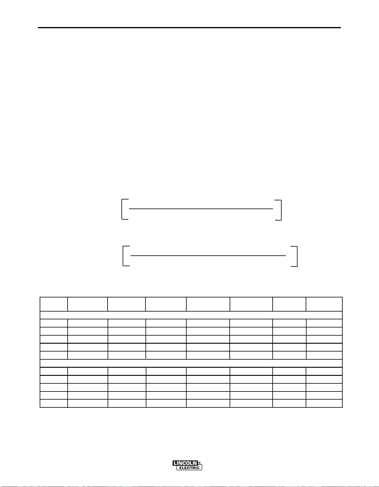
should be determined. In Table D.1 Measurement
esults suggested nominal set points are listed. The
R
power source and resistive load should be set approximately to these voltage and current set points, e.g. 28
V @ 200 A, 36 V @ 400 A, etc. The reference meter
readings should be compared to the ARC TRACKER™ digital meters.
% Dev Equations:
% Dev
(As Found)
ARC TRACKER™ As Found - Reference Meter Value
=
Reference Meter Value
The reference meter readings should be entered into
Table D.1 in the reference meter value column. The
ARC TRACKER™ meter readings should be entered
nto Table 1 in the ARC TRACKER™ as found col-
i
umn.
The % deviation can be determined by calculation
using the reference meter values and the as found
values (see % Dev Equations). The - limits and + limits can be determined by multiplying the reference
meter values by the desired accuracy of the ARC
TRACKER™ meters (for example, +2% limit = 1.02 x
reference meter value).
If the ARC TRACKER™ digital meters are within the
desired limits, calibration adjustments are not necessary. As le ft and % deviation values should be
entered into Table D.1. If calibration is required, then
continue with the Adjustment Procedure.
x100%
% Dev
(As Left)
Nominal Reference Arc Tracker % Deviation Arc Tracker % Deviation (+) Limit (-) Limit
Set Point Meter Value As Found As Found As Left As Left
28V
35V
44V
44V
44V
200A
400A
600A
800A
1000A
ARC TRACKER™ As Left - ARC TRACKER™ As Found
=
TABLE D.1 MEASUREMENT RESULTS
Reference Meter Value
DC Voltage
DC Amperes
x100%
ARC TRACKER™
Page 21
-3
AMMETER
DISPLAY
VOLT METER
DISPLAY
AMMETER
CALIBRATION
ADJUST
VOLT METER
CALIBRATION
ADJUST
CALIBRATION
MODE LED
MESSAGE
D
ISPLAY
LEFT PUSH
BUTTON
RIGHT
PUSH
BUTTON
CENTER
KNOB
P.0
User
Exit
Prefs
P.83
Calibrate V & I ?
Yes
P.83
Please Wait...
P.83
Adjust Knobs
Done
P.83
Is output OFF?
Yes
Cancel
P.83
Enable Output
Cancel
D
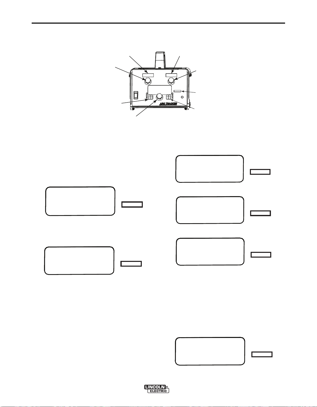
Adjustment Procedure:
MAINTENANCE
ARC TRACKER™ Front Panel
FIGURE D.2
D
-3
1. With the po w e r source of f , connect the ARC
TRACKER™ being calibrated to input power and
turn the ARC TRACKER™ on.
2. Enter into the calibration menu by pressing both
the left and right push buttons on the ARC TRACKER™ user-interface. The Calibration Mode LED
will illuminate and the message display will look
like this:
3. Tu rn the center knob until paramete r P.83 is
reached. Press the right pushbutton to enter into
Calibration mode.
4. With the power source turned off, press the right
pushbutton to zero the unit. The unit will take a few
seconds to zero.
5. Turn on the power source to provide the maximum
calibration current and voltage, e.g. 1000 A, 44 V.
The ARC TRACKER™ will begin to display the voltage, amperage, & arc time, and will begin to calculate and display heat input.
6. Press the right push button to begin calibration of
the volt meter and ammeter located on the ARC
TRACKER™ under calibration.
ARC TRACKER™
Page 22

-4
D
7. Turn the Volt Meter Calibration Adjust knob located
under the volt meter on the user-interface until it
matches the reference volt meter.
8. Turn the Ammeter Calibration Adjust knob under
he ammeter on the user-interface until it matches
t
the reference ammeter.
9. When both the volts display and amps display on
the unit being calibrated are dialed in, press the
right pushbutton to accept the calibration values.
10. Turn the center knob until parameter P.0 is dis-
played. Press the left push button to EXIT.
11. Verify that the calibration was completed suc-
cessfully by adjusting the power source to different set points for current and voltage comparing
the volts display and amps display on the unit
being calibrated to the reference volt meter and
ammeter. See Table D.1.
12. As left values should be entered into Table D.1.
Then the % deviation can be calculated by comparing the reference meter values to the ARC
TRACKER™ as left values.
MAINTENANCE
D
-4
ARC TRACKER™
Page 23

E-1
TROUBLESHOOTING
HOW TO USE TROUBLESHOOTING GUIDE
WARNING
Service and Repair should only be performed by Lincoln Electric Factory Trained Personnel.
Unauthorized repairs performed on this equipment may result in danger to the technician and
machine operator and will invalidate your factory warranty. For your safety and to avoid Electrical
Shock, please observe all safety notes and precautions detailed throughout this manual.
__________________________________________________________________________
E-1
This Troubleshooting Guide is provided to help you
locate and repair possible machine malfunctions.
Simply follow the three-step procedure listed below.
Step 1. LOCATE PROBLEM (SYMPTOM).
Look under the column labeled “PROBLEM (SYMPTOMS)”. This column describes possible symptoms
that the machine may exhibit. Find the listing that
best describes the symptom that the machine is
exhibiting.
Step 2. POSSIBLE CAUSE.
The second column labeled “POSSIBLE CAUSE” lists
the obvious external possibilities that may contribute
to the machine symptom.
Step 3. RECOMMENDED COURSE OF ACTION
This column provides a course of action for the
Possible Cause, generally it states to contact your
local Lincoln Authorized Field Service Facility.
If you do not understand or are unable to perform the
Recommended Course of Action safely, contact your
local Lincoln Authorized Field Service Facility.
CAUTION
If for any reason you do not understand the test procedures or are unable to perform the tests/repairs safely, contact your
Local Lincoln Authorized Field Service Facility for technical troubleshooting assistance before you proceed.
ARC TRACKER™
Page 24
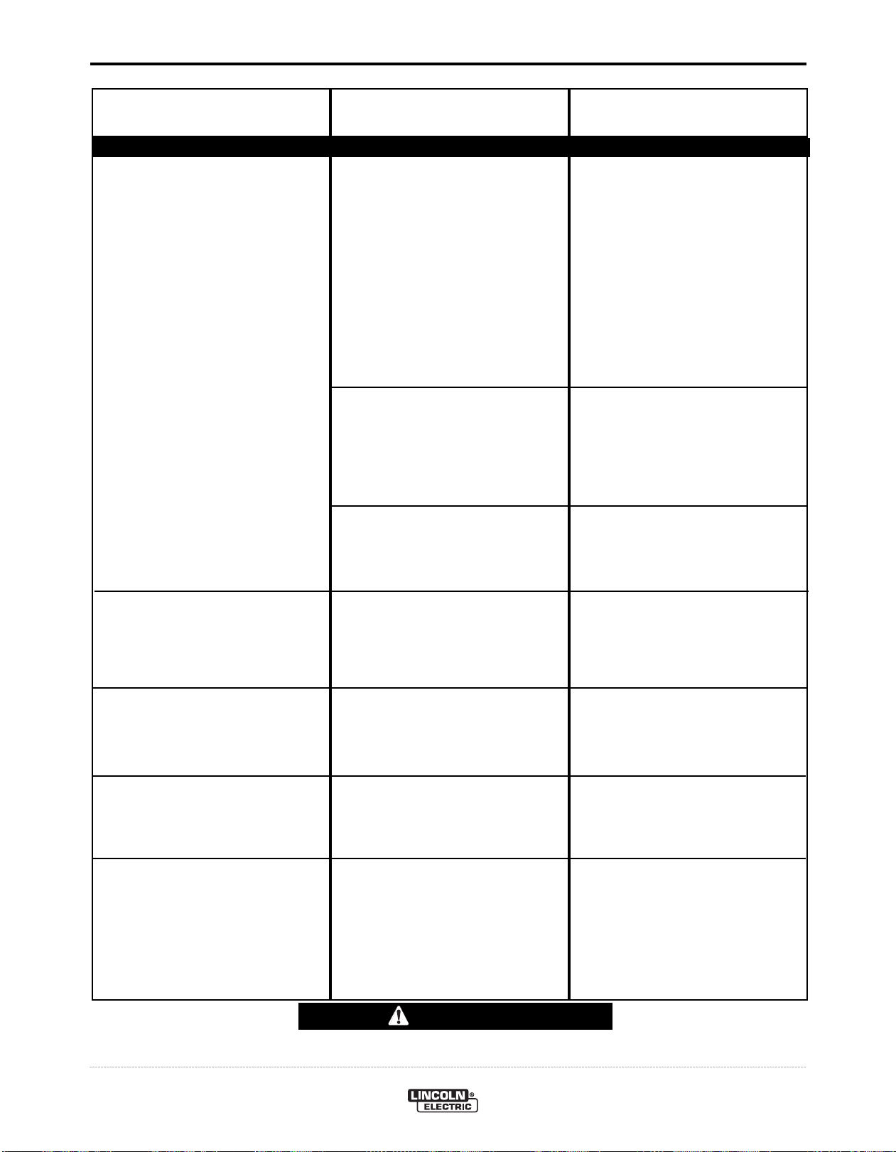
E-2
Observe all Safety Guidelines detailed throughout this manual
PROBLEMS
(SYMPTOMS)
TROUBLESHOOTING
POSSIBLE
CAUSE
Ethernet
E-2
RECOMMENDED
COURSE OF ACTION
Cannot Connect.
1. Physical connection.
2. IP address information.
3. Ethernet Speed.
1. Verify that the correct patch cable
or cross over cable is being used
(refer to local IT department for
assistance).
1a. Verify the cables are fully insert-
ed into the bulk head connector.
1b. The LED under the PC board
ethernet connector will be lit
when the machine is connected
to another network device.
2. Use the appropriate PC utility to
verify the correct IP address information has been entered.
2a. Verify no duplicate IP addresses
exist on the network.
3. Ve r i f y that the ne t work device
connected to the Power Wave is
either a 10-baseT de v i c e or a
10/100-baseT device.
Connection Drops while welding.
Does not di splay amps, volts , or
energy while welding.
Displays amps and energy, but not
volts.
1. Cable Location.
1. We l d circuit cu r r e n t flowing in
wrong direction.
2. Sense leads not connected properly or broken.
1. Verify Network cable is not located next to current carrying conductors. This would include input
power cables and welding output
cables.
1. Weld cables must be connected
so current flows into the left weld
terminals and out the right weld
terminals (viewed from rear).
1. Confirm continuity.
2. Red clip lead must be attached to
“+” and black clip lead must be
attached to “-”.
CAUTION
If for any reason you do not understand the test procedures or are unable to perform the tests/repairs safely, contact your
Local Lincoln Authorized Field Service Facility for technical troubleshooting assistance before you proceed.
ARC TRACKER™
Page 25

E-3
TROUBLESHOOTING
E-3
USING THE STATUS LED TO TROUBLESHOOT SYSTEM PROBLEMS
Not all of the Arc Tracker™errors will be displayed on the user interface. If a problem occurs it is important to note the condition of the status lights. Therefore, prior to cycling power to the system, check the power source status light for error
sequences as noted below.
Error conditions are indicated in the following Table E.1.
TABLE E.1
Light
Condition
Steady Green
Blinking Green
Alternating Green and Red
Meaning
System OK.
Occurs during power up or a system reset. Normal for first 1-10 sec-
onds after power is turned on, or if the system configuration is changed
during operation.
Non-recoverable system fault. If the Status lights are flashing any com-
bination of red and green, errors are present. Read the error code(s)
before the machine is turned off.
Error Code interpretation through the Status light. Individual code
digits are flashed in red with a long pause between digits. If more than
one code is present, the codes will be separated by a green light. Only
active error conditions will be accessible through the Status Light.
Error codes can also be retrieved with the Diagnostics Utility (includ-
ed on the Service Navigator CD or available at www.power-
wavesoftware.com). This is the preferred method, since it can access
historical information contained in the error logs.
To clear the active error(s), turn power source off, and back on to
reset.
CAUTION
If for any reason you do not understand the test procedures or are unable to perform the tests/repairs safely, contact your
Local Lincoln Authorized Field Service Facility for technical troubleshooting assistance before you proceed.
ARC TRACKER™
Page 26
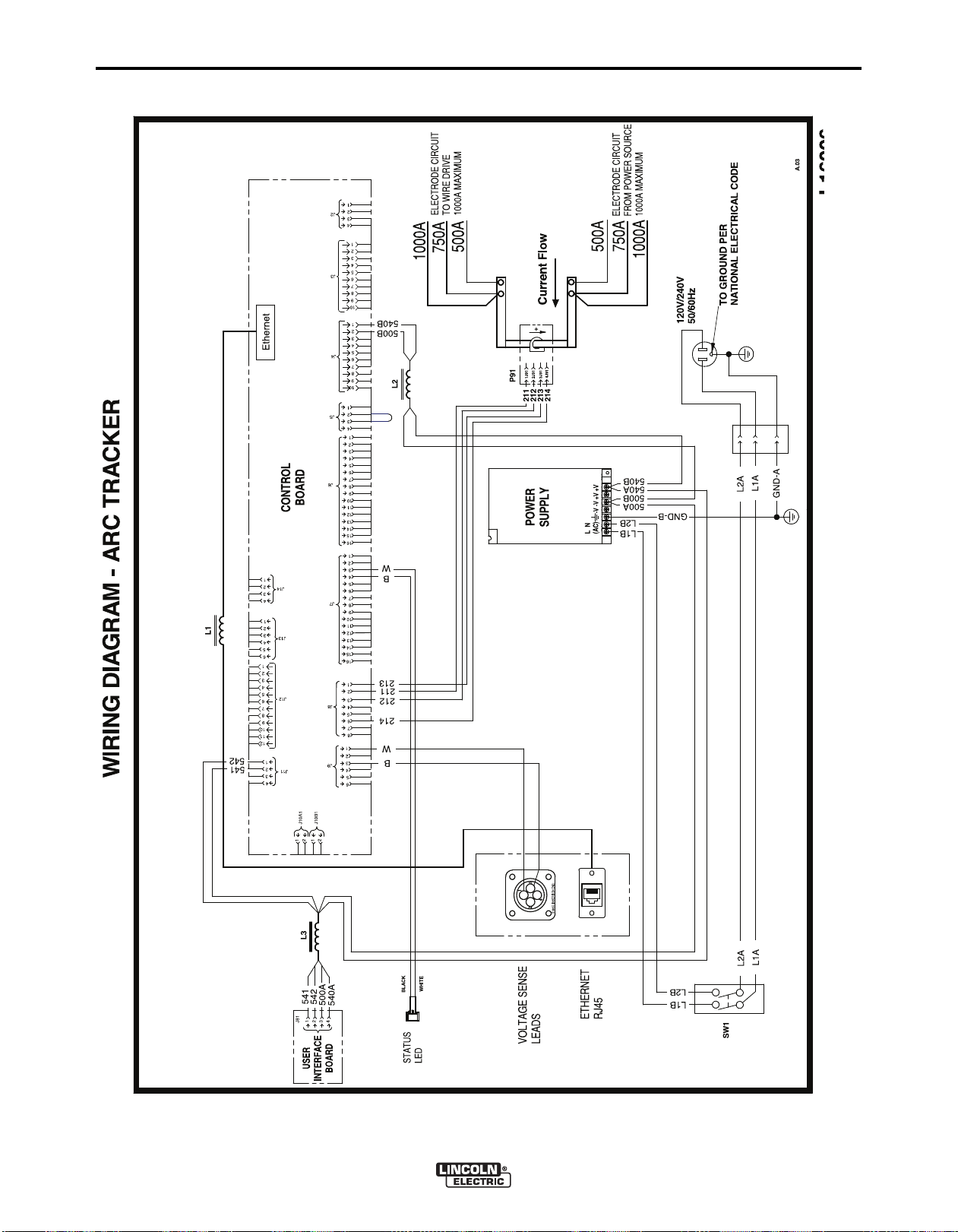
F-1
™
DIAGRAMS
F-1
ARC TRACKER™
machine on one of the enclosure panels. If the diagram is illegible, write to the Service Department for a replacement. Give the equipment code number.
NOTE: This diagram is for reference only. It may not be accurate for all machines covered by this manual. The specific diagram for a particular code is pasted inside the
Page 27
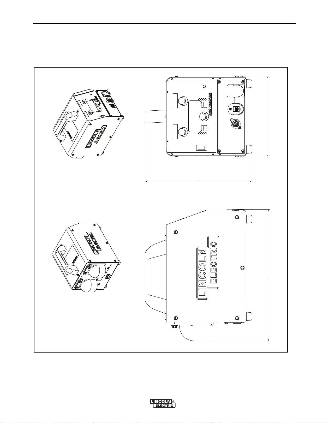
F-2
L15970
A.02
14.48
8.92
11.79
DIMENSION PRINT
F-2
ARC TRACKER™
Page 28

Arc Tracker - 11742
Page 29

Index of Sub Assemblies - 11742
KEY PART NUMBER DESCRIPTION QTY
P-675-A INDEX OF SUB ASSEMBLIES AR
P-675-B.2 MISCELLANEOUS ITEMS AR
1 P-675-C BASE ASSEMBLY AND FRONT COMPONENTS AR
2 P-675-D COVER ASSEMBLY AR
3 P-675-E SHELF ASSEMBLY AR
4 P-675-F BASE ASBLY REAR COMPONENTS AR
5 P-675-G WRAPAROUND ASSEMBLY AR
Printed 05/25/2017 at 07:42:26. Produced by Enigma.
Arc Tracker - 11742 1
Page 30
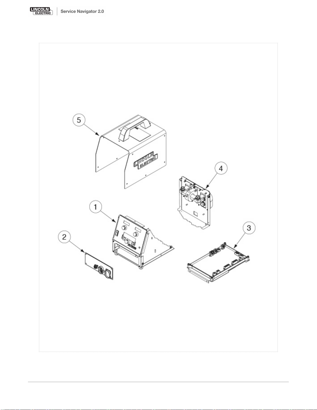
Index of Sub Assemblies - 11742
P-675-A.jpg
2 Arc Tracker - 11742
Printed 05/25/2017 at 07:42:26. Produced by Enigma.
Page 31

Miscellaneous Items
KEY PART NUMBER DESCRIPTION QTY
9SS28636 POWER CORD 1
9SM17585-8 ARC SENSE LEADS 1
9SM19969-10 ETHERNET PATCH CABLE ASBLY 1
Printed 05/25/2017 at 07:42:26. Produced by Enigma.
Arc Tracker - 11742 3
Page 32

Base Assembly and Front Components
KEY PART NUMBER DESCRIPTION QTY
1 9SG5881 BASE ASBLY 1
2A 9ST14882-3 BUMPER 4
2B 9SS9225-36 THREAD FORMING SCREW (CUTTING) 4
9SS9262-60 FLAT WASHER 4
9ST9695-1 LOCKWASHER 4
7A 9SS28645-3 SOFTWARE USER INTERFACE PC BD 1
9ST10082-12 SEMS SCREW 4
8A 9SCF000042 #8-32HN 2
9ST9695-3 LOCKWASHER 1
10 9ST10800-58 SWITCH-DPST 1
10A 9SS28672-1 ROCKER SWITCH BOOT 1
11 9SM22710 COVER ASSEMBLY 1
20 9SM22622 DECAL 1
21 9SS23055-1 BUTTON COVER 2
22A 9ST13639-3 KNOB 3
22B 9ST14034-4 SHAFT SEAL 3
9SS18250-988 PLUG AND LEAD ASBLY 1
9SS23740-2 LED PANEL MOUNT ASSEMBLY 1
23B 9ST13657-7H24 LED-T-1 3/4BI-COLORRED/GREEN 1
9SS23093-1 LED LENS CLEAR 1
9SS23094-1 RETAINING O RING 1
Printed 05/25/2017 at 07:42:26. Produced by Enigma.
Arc Tracker - 11742 5
Page 33
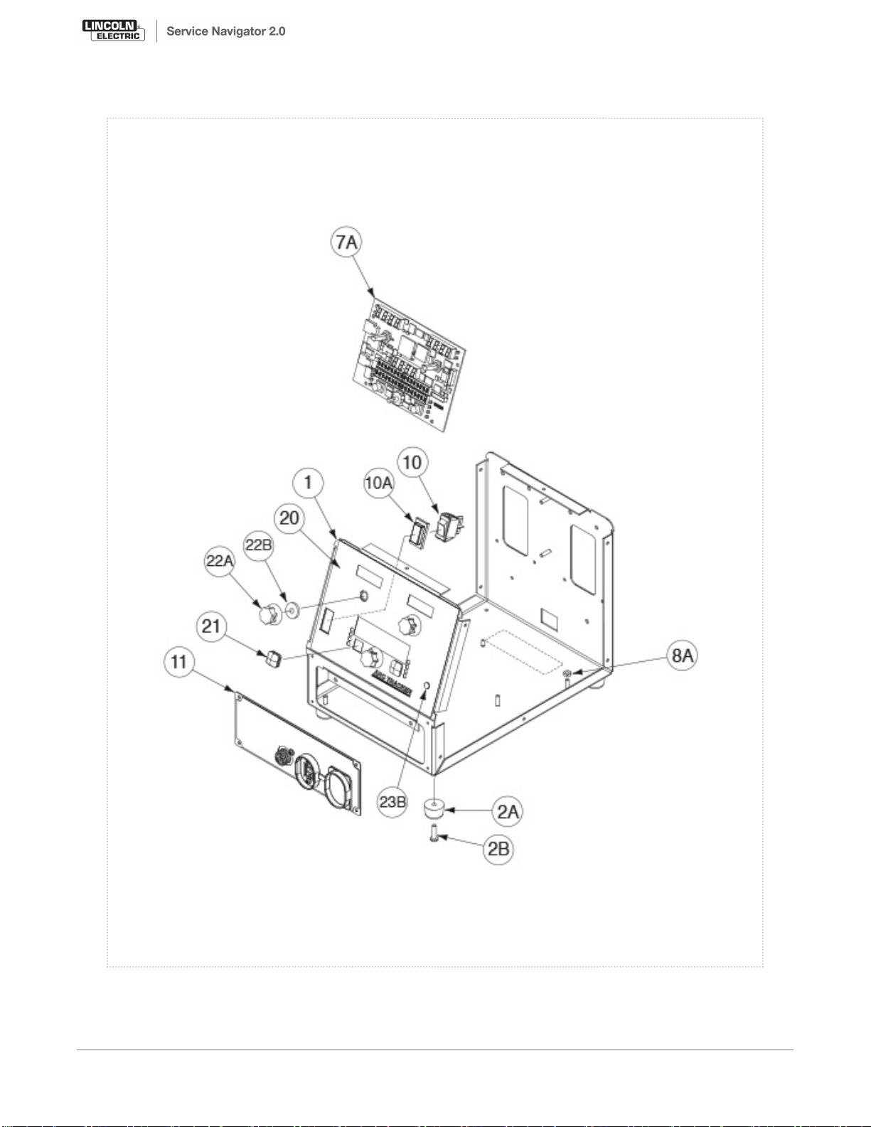
Base Assembly and Front Components
P-675-C.jpg
6 Arc Tracker - 11742
Printed 05/25/2017 at 07:42:26. Produced by Enigma.
Page 34

Cover Assembly
KEY PART NUMBER DESCRIPTION QTY
9SM22710 COVER ASSEMBLY 1
1A 9SS28614 COVER PLATE 1
2 9SM22622 DECAL 1
9SS18250-989 PLUG AND LEAD ASBLY 1
3A 9SS18657 SQUARE FLANGE FEMALE RECEPTACLE 1
3B 9SS8025-96 SELF TAPPING SCREW 2
4 9SM19969-14 ETHERNET RECEPTACLE 1
5A 9SM22444 ETHERNET COVER 1
5B 9SS8025-118 SELF TAPPING SCREW 2
10 9SS8025-96 SELF TAPPING SCREW 4
Printed 05/25/2017 at 07:42:26. Produced by Enigma.
Arc Tracker - 11742 7
Page 35
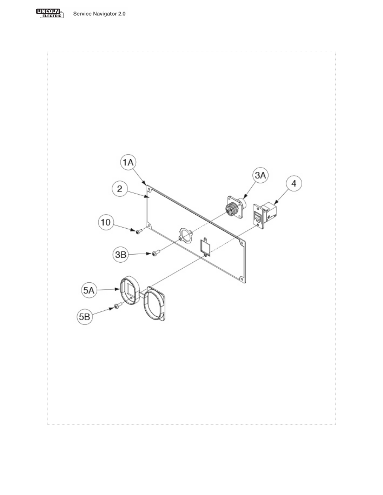
Cover Assembly
P-675-D.jpg
8 Arc Tracker - 11742
Printed 05/25/2017 at 07:42:26. Produced by Enigma.
Page 36

Shelf Assembly
KEY PART NUMBER DESCRIPTION QTY
1 9SS28528 CONTROL BOARD SHELF 1
2A 9SS28631-5 SOFTWARE CONTROL BOARD 1
2B 9ST9187-13 #10-24HLN-1817/1-NYLON INSERT 4
9SS18250-990 PLUG & LEAD ASSEMBLY 1
4 9SM22623 POWER SUPPLY 1
5A 9SS28538 POWER SUPPLY STRAP 1
5B 9ST9695-3 LOCKWASHER 2
5C 9SCF000042 #8-32HN 2
9SS18250-992 PLUG & LEAD ASBLY 1
9SS8025-92 SELF TAPPING SCREW 4
Printed 05/25/2017 at 07:42:26. Produced by Enigma.
Arc Tracker - 11742 9
Page 37
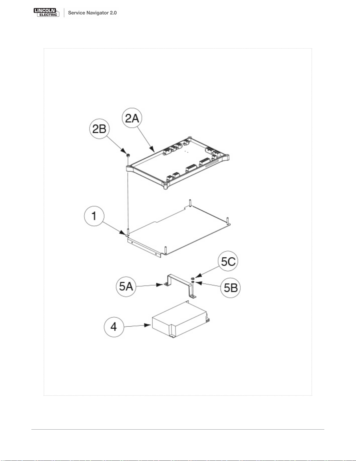
Shelf Assembly
P-675-E.jpg
10 Arc Tracker - 11742
Printed 05/25/2017 at 07:42:26. Produced by Enigma.
Page 38

Base Asbly Rear Components
KEY PART NUMBER DESCRIPTION QTY
3 9SS28594 POWER ENTRY CONNECTOR 1
4A 9SS29308 POWER ENTRY COVER 1
4B 9SS8025-92 SELF TAPPING SCREW 2
12A 9SS18504-9 CURRENT TRANSDUCER 1
9SS18250-991 PLUG AND LEAD ASBLY 1
9ST9695-3 LOCKWASHER 2
12D 9SCF000042 #8-32HN 2
9SM22761 OUTPUT STUD INSULATION ASBLY 1
14A 9SS28715 CONNECTION STRAP 2
14B 9SCF000388 1/2-13 X 2.00 HHCS 4
14C 9SS9262-1 PLAIN WASHER 4
14D 9SE106A-15 LOCKWASHER 4
14E 9ST10114 1/2-13BR-HJN 4
14F 9SS28716 INSULATION 2
14G 9ST3960 FLANGE NUT 4
14H 9SS8025-92 SELF TAPPING SCREW 4
16A 9SM20007 OUTPUT STUD COVER 2
16B 9SS25669 OUTPUT STUD COVER PLATE 2
16C 9SS9225-66 SELF TAPPING SCREW 4
17A 9SS26945 BUS BAR 1
17B 9SCF000030 1/2-13X1.25HHCS 2
17C 9SS9262-1 PLAIN WASHER 2
17D 9SE106A-15 LOCKWASHER 2
17E 9SCF000054 1/2-13HJN 2
18 9SM22622 DECAL 1
26 9SM22622 DECAL 1
Printed 05/25/2017 at 07:42:26. Produced by Enigma.
Arc Tracker - 11742 11
Page 39
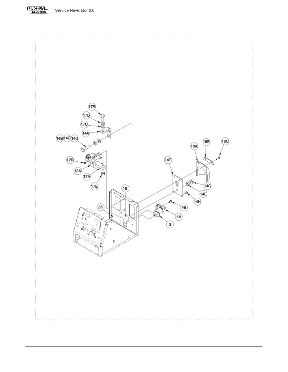
Base Asbly Rear Components
P-675-F.jpg
12 Arc Tracker - 11742
Printed 05/25/2017 at 07:42:26. Produced by Enigma.
Page 40

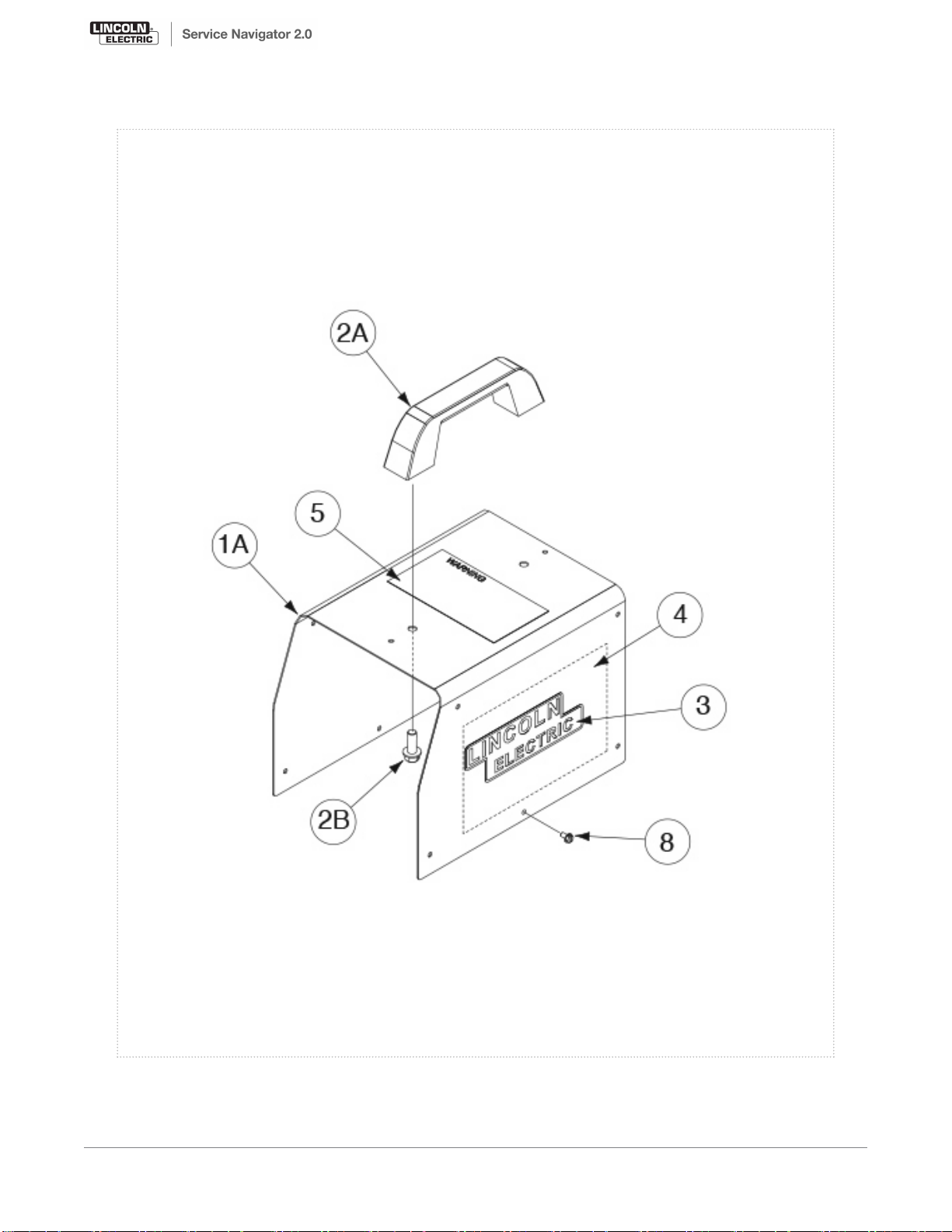
Wraparound Assembly
KEY PART NUMBER DESCRIPTION QTY
9SL13161 WRAPAROUND ASBLY 1
1A 9SM21346 WRAPAROUND 1
2A 9SM15446 HANDLE 1
2B 9SS9225-53 THREAD FORMING SCREW 2
3 9SS27368-2 DECAL - 7IN LINCOLN LOGO 2
4 9SL16006 WIRING DIAGRAM 1
5 9SM16196 DECAL-WARNING 1
8 9SS8025-92 SELF TAPPING SCREW 12
Printed 05/25/2017 at 07:42:26. Produced by Enigma.
Arc Tracker - 11742 13
Page 41
Wraparound Assembly
P-675-G.jpg
14 Arc Tracker - 11742
Printed 05/25/2017 at 07:42:26. Produced by Enigma.
Page 42
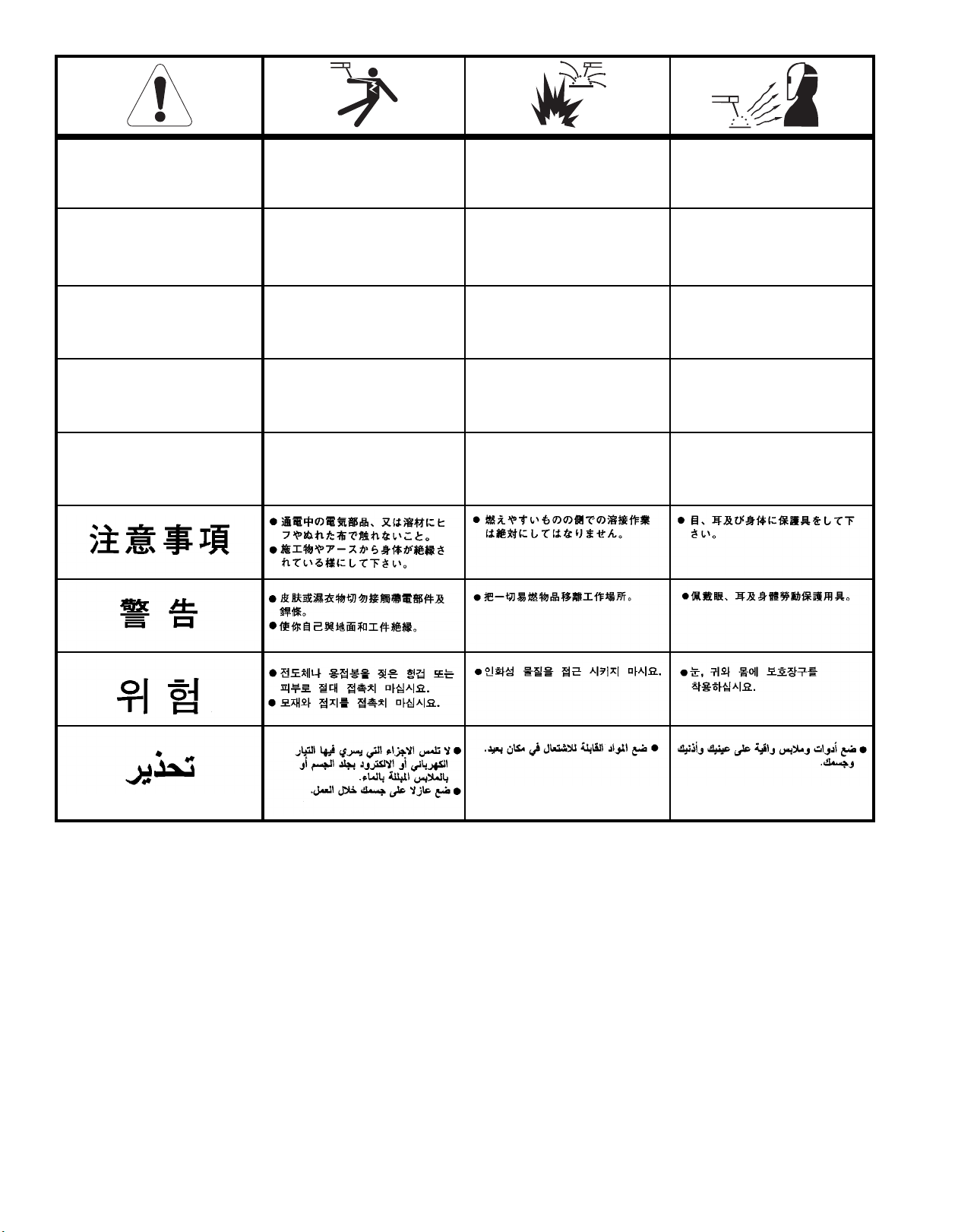
WARNING
panish
S
AVISO DE
PRECAUCION
French
ATTENTION
erman
G
WARNUNG
Portuguese
ATENÇÃO
Japanese
Chinese
Do not touch electrically live parts or
•
electrode with skin or wet clothing.
Insulate yourself from work and
•
ground.
No toque las partes o los electrodos
•
bajo carga con la piel o ropa mojada.
Aislese del trabajo y de la tierra.
•
Ne laissez ni la peau ni des vêtements
•
mouillés entrer en contact avec des
pièces sous tension.
Isolez-vous du travail et de la terre.
•
Berühren Sie keine stromführenden
•
Teile oder Elektroden mit Ihrem
Körper oder feuchter Kleidung!
Isolieren Sie sich von den Elektroden
•
und dem Erdboden!
Não toque partes elétricas e electro-
•
dos com a pele ou roupa molhada.
Isole-se da peça e terra.
•
Keep flammable materials away.
•
Mantenga el material combustible
•
fuera del área de trabajo.
Gardez à l’écart de tout matériel
•
inflammable.
Entfernen Sie brennbarres Material!
•
Mantenha inflamáveis bem guarda-
•
dos.
Wear eye, ear and body protection.
•
Protéjase los ojos, los oídos y el
•
cuerpo.
Protégez vos yeux, vos oreilles et
•
votre corps.
Tragen Sie Augen-, Ohren- und Kör-
•
perschutz!
Use proteção para a vista, ouvido e
•
corpo.
Korean
Arabic
READ AND UNDERSTAND THE MANUFACTURER’S INSTRUCTION FOR THIS EQUIPMENT AND THE CONSUMABLES TO BE USED AND FOLLOW YOUR EMPLOYER’S SAFETY PRACTICES.
SE RECOMIENDA LEER Y ENTENDER LAS INSTRUCCIONES DEL FABRICANTE PARA EL USO DE ESTE
EQUIPO Y LOS CONSUMIBLES QUE VA A UTILIZAR, SIGA LAS MEDIDAS DE SEGURIDAD DE SU SUPERVISOR.
LISEZ ET COMPRENEZ LES INSTRUCTIONS DU FABRICANT EN CE QUI REGARDE CET EQUIPMENT ET
LES PRODUITS A ETRE EMPLOYES ET SUIVEZ LES PROCEDURES DE SECURITE DE VOTRE
EMPLOYEUR.
LESEN SIE UND BEFOLGEN SIE DIE BETRIEBSANLEITUNG DER ANLAGE UND DEN ELEKTRODENEINSATZ DES HERSTELLERS. DIE UNFALLVERHÜTUNGSVORSCHRIFTEN DES ARBEITGEBERS SIND EBENFALLS ZU BEACHTEN.
Page 43

Keep your head out of fumes.
•
Use ventilation or exhaust to remove
•
fumes from breathing zone.
Los humos fuera de la zona de res-
•
piración.
Mantenga la cabeza fuera de los
•
humos. Utilice ventilación o
aspiración para gases.
Gardez la tête à l’écart des fumées.
•
Utilisez un ventilateur ou un aspira-
•
teur pour ôter les fumées des zones
de travail.
Vermeiden Sie das Einatmen von
•
Schweibrauch!
Sorgen Sie für gute Be- und
•
Entlüftung des Arbeitsplatzes!
Mantenha seu rosto da fumaça.
•
Use ventilação e exhaustão para
•
remover fumo da zona respiratória.
Turn power off before servicing.
•
Desconectar el cable de alimentación
•
de poder de la máquina antes de iniciar cualquier servicio.
Débranchez le courant avant l’entre-
•
tien.
Strom vor Wartungsarbeiten abschal-
•
ten! (Netzstrom völlig öffnen;
Maschine anhalten!)
Não opere com as tampas removidas.
•
Desligue a corrente antes de fazer
•
serviço.
Não toque as partes elétricas nuas.
•
Do not operate with panel open or
•
guards off.
No operar con panel abierto o
•
guardas quitadas.
N’opérez pas avec les panneaux
•
ouverts ou avec les dispositifs de
protection enlevés.
Anlage nie ohne Schutzgehäuse oder
•
Innenschutzverkleidung in Betrieb
setzen!
Mantenha-se afastado das partes
•
moventes.
Não opere com os paineis abertos ou
•
guardas removidas.
WARNING
panish
S
AVISO DE
PRECAUCION
French
ATTENTION
erman
G
WARNUNG
Portuguese
ATENÇÃO
Japanese
Chinese
Korean
Arabic
LEIA E COMPREENDA AS INSTRUÇÕES DO FABRICANTE PARA ESTE EQUIPAMENTO E AS PARTES DE
USO, E SIGA AS PRÁTICAS DE SEGURANÇA DO EMPREGADOR.
Page 44

CUSTOMER ASSISTANCE POLICY
The business of The Lincoln Electric Company is manufacturing and
selling high quality welding equipment, consumables, and cutting
equipment. Our challenge is to meet the needs of our customers and
o exceed their expectations. On occasion, purchasers may ask
t
Lincoln Electric for advice or information about their use of our
products. We respond to our customers based on the best information
in our possession at that time. Lincoln Electric is not in a position to
warrant or guarantee such advice, and assumes no liability, with
respect to such information or advice. We expressly disclaim any
warranty of any kind, including any warranty of fitness for any
customer’s particular purpose, with respect to such information or
advice. As a matter of practical consideration, we also cannot assume
any responsibility for updating or correcting any such information or
advice once it has been given, nor does the provision of information
or advice create, expand or alter any warranty with respect to the sale
of our products.
Lincoln Electric is a responsive manufacturer, but the selection and
use of specific products sold by Lincoln Electric is solely within the
control of, and remains the sole responsibility of the customer. Many
variables beyond the control of Lincoln Electric affect the results
obtained in applying these types of fabrication methods and service
requirements.
Subject to Change – This information is accurate to the best of our
knowledge at the time of printing. Please refer to
www.lincolnelectric.com for any updated information.
 Loading...