

Page 1
IM3004
01/2005
Rev. 1
POWERTEC
280C, 350C & 420C PRO
OPERATOR’S MANUAL
MANUALE OPERATIVO
BEDIENUNGSANLEITUNG
MANUAL DE INSTRUCCIONES
MANUEL D'UTILISATION
BRUKSANVISNING OG DELELISTE
GEBRUIKSAANWIJZING
BRUKSANVISNING
INSTRUKCJA OBSŁUGI
BESTER S.A.
ul. Jana III Sobieskiego 19A, 58-260 Bielawa, Poland
www.lincolnelectriceurope.com
Page 2

II
Declaration of conformity
Dichiarazione di conformità
Konformitätserklärung
Declaración de conformidad
Déclaration de conformité
Samsvars erklæring
Verklaring van overeenstemming
Försäkran om överensstämmelse
Deklaracja zgodności
BESTER S.A.
Declares that the welding machine:
Dichiara che Il generatore per saldatura tipo:
Erklärt, daß die Bauart der Maschine:
Declara que el equipo de soldadura:
Déclare que le poste de soudage:
Bekrefter at denne sveisemaskin:
Verklaart dat de volgende lasmachine:
Försäkrar att svetsomriktaren:
Deklaruje, że spawalnicze źródło energii:
POWERTEC 280C, 350C, & 420C PRO
conforms to the following directives:
è conforme alle seguenti direttive:
den folgenden Bestimmungen entspricht:
es conforme con las siguientes directivas:
est conforme aux directives suivantes:
er i samsvar med følgende direktiver:
overeenkomt conform de volgende richtlijnen:
överensstämmer med följande direktiv:
spełnia następujące wytyczne:
73/23/CEE, 89/336/CEE
and has been designed in compliance with the following
standards:
ed è stato progettato in conformità alle seguenti norme:
und in Übereinstimmung mit den nachstehenden normen
hergestellt wurde:
y ha sido diseñado de acuerdo con las siguientes
normas:
et qu'il a été conçu en conformité avec les normes:
og er produsert og testet iht. følgende standarder:
en is ontworpen conform de volgende normen:
och att den konstruerats i överensstämmelse med
följande standarder:
i że zostało zaprojektowane zgodnie z wymaganiami
następujących norm:
EN 60974-1, EN 60974-10
Tomasz Domagalski
Operations Director
BESTER S.A., ul. Jana III Sobieskiego 19A, 58-260 Bielawa, Poland
11/04
Page 3

III
11/04
THANKS! For having choosen the QUALITY of the Lincoln Electric products.
• Please Examine Package and Equipment for Damage. Claims for material damaged in shipment must be notified
immediately to the dealer.
• For future reference record in the table below your equipment identification information. Model Name, Code &
Serial Number can be found on the machine rating plate.
GRAZIE! Per aver scelto la QUALITÀ dei prodotti Lincoln Electric.
• Esamini Imballo ed Equipaggiamento per rilevare eventuali danneggiamenti. Le richieste per materiali danneggiati
dal trasporto devono essere immediatamente notificate al rivenditore.
• Per ogni futuro riferimento, compilare la tabella sottostante con le informazioni di identificazione equipaggiamento.
Modello, Codice (Code) e Matricola (Serial Number) sono reperibili sulla targa dati della macchina.
VIELEN DANK! Dass Sie sich für ein QUALITÄTSPRODUCKT von Lincoln Electric entschieden haben.
• Bitte überprüfen Sie die Verpackung und den Inhalt auf Beschädigungen. Transportschäden müssen sofort dem
Händler gemeldet werden.
• Damit Sie Ihre Gerätedaten im Bedarfsfall schnell zur Hand haben, tragen Sie diese in die untenstehende Tabelle
ein. Typenbezeichnung, Code- und Seriennummer finden Sie auf dem Typenschild Ihres Gerätes.
GRACIAS! Por haber escogido los productos de CALIDAD Lincoln Electric.
• Por favor, examine que el embalaje y el equipo no tengan daños. La reclamación del material dañado en el
transporte debe ser notificada inmediatamente al proveedor.
• Para un futuro, a continuación encontrará la información que identifica a su equipo. Modelo, Code y Número de
Serie los cuales pueden ser localizados en la placa de características de su equipo.
MERCI! Pour avoir choisi la QUALITÉ Lincoln Electric.
• Vérifiez que ni l’équipement ni son emballage ne sont endommagés. Toute réclamation pour matériel
endommagé doit être immédiatement notifiée à votre revendeur.
• Notez ci-dessous toutes les informations nécessaires à l’identification de votre équipement. Le nom du Modèle
ainsi que les numéros de Code et Série figurent sur la plaque signalétique de la machine.
TAKK! For at du har valgt et KVALITETSPRODUKT fra Lincoln Electric.
• Kontroller emballsjen og produktet for feil eller skader. Eventuelle feil eller transportskader må umiddelbart
rapporteres dit du har kjøpt din maskin.
• For fremtidig referanse og for garantier og service, fyll ut den tekniske informasjonen nedenfor i dette avsnittet.
Modell navn, Kode & Serie nummer finner du på den tekniske platen på maskinen.
BEDANKT! Dat u gekozen heeft voor de KWALITEITSPRODUCTEN van Lincoln Electric.
• Controleert u de verpakking en apparatuur op beschadiging. Claims over transportschade moeten direct aan de
dealer of aan Lincoln electric gemeld worden.
• Voor referentie in de toekomst is het verstandig hieronder u machinegegevens over te nemen. Model Naam,
Code & Serienummer staan op het typeplaatje van de machine.
TACK! För att ni har valt en KVALITETSPRODUKT från Lincoln Electric.
• Vänligen kontrollera förpackning och utrustning m.a.p. skador. Transportskador måste omedelbart anmälas till
återförsäljaren eller transportören.
• Notera informationen om er utrustnings identitet i tabellen nedan. Modellbeteckning, code- och serienummer hittar
ni på maskinens märkplåt.
DZIĘKUJEMY! Za docenienie JASKOŚCI produktów Lincoln Electric.
• Proszę sprawdzić czy opakownie i sprzęt nie są uszkodzone. Reklamacje uszkodzeń powstałych podczas
transportu muszą być natychmiast zgłoszone do dostawcy (dystrybutora).
• Dla ułatwienia prosimy o zapisanie na tej stronie danych identyfikacyjnych wyrobów. Nazwa modelu, Kod i Numer
Seryjny, które możecie Państwo znaleźć na tabliczce znamionowej wyrobu.
Model Name, Modello, Typenbezeichnung, Modelo, Nom du modèle, Modell navn, Model Naam, Modellbeteckning,
Nazwa modelu:
………………...…………………………….…………………………………………………………………………………………..
Code & Serial number, Code (codice) e Matricola, Code- und Seriennummer, Code y Número de Serie, Numéros de
Code et Série, Kode & Serie nummer, Code en Serienummer, Code- och Serienummer, Kod i numer Seryjny:
………………….……………………………………………….. …………………………………………………….……………..
Date & Where Purchased, Data e Luogo d’acquisto, Kaufdatum und Händler, Fecha y Nombre del Proveedor, Lieu et
Date d’acquisition, Kjøps dato og Sted, Datum en Plaats eerste aankoop, Inköpsdatum och Inköpsställe, Data i Miejsce
zakupu:
…………………………………………………………………... ……………………….…………………………………………..
Page 4

IV
ENGLISH INDEX
Safety .......................................................................................................................................................................... A-1
Installation and Operator Instructions .......................................................................................................................... A-2
Electromagnetic Compatibility (EMC) .......................................................................................................................... A-7
Technical Specifications .............................................................................................................................................. A-8
INDICE ITALIANO
Sicurezza..................................................................................................................................................................... B-1
Installazione e Istruzioni Operative.............................................................................................................................. B-2
Compatibilità Elettromagnetica (EMC)......................................................................................................................... B-7
Specifiche Tecniche..................................................................................................................................................... B-8
INHALTSVERZEICHNIS DEUTSCH
Sicherheitsmaßnahmen / Unfallschutz ........................................................................................................................ C-1
Installation und Bedienungshinweise........................................................................................................................... C-2
Elektromagnetische Verträglichkeit (EMC) .................................................................................................................. C-7
Technische Daten........................................................................................................................................................ C-8
INDICE ESPAÑOL
Seguridad .................................................................................................................................................................... D-1
Instalación e Instrucciones de Funcionamiento ........................................................................................................... D-2
Compatibilidad Electromagnética (EMC)..................................................................................................................... D-7
Especificaciones Técnicas........................................................................................................................................... D-8
INDEX FRANÇAIS
Sécurité ....................................................................................................................................................................... E-1
Installation et Instructions d'Utilisation ......................................................................................................................... E-2
Compatibilité Electromagnétique (CEM)...................................................................................................................... E-7
Caractéristiques Techniques ....................................................................................................................................... E-8
NORSK INNHOLDSFORTEGNELSE
Sikkerhetsregler............................................................................................................................................................F-1
Installasjon og Brukerinstruksjon ..................................................................................................................................F-2
Elektromagnetisk Kompatibilitet (EMC) ........................................................................................................................F-7
Tekniske Spesifikasjoner ..............................................................................................................................................F-8
NEDERLANDSE INDEX
Veiligheid..................................................................................................................................................................... G-1
Installatie en Bediening................................................................................................................................................ G-2
Elektromagnetische Compatibiliteit (EMC) ..................................................................................................................G-7
Technische Specificaties ............................................................................................................................................. G-8
SVENSK INNEHÅLLSFÖRTECKNING
Säkerhetsanvisningar .................................................................................................................................................. H-1
Instruktioner för Installation och Handhavande............................................................................................................ H-2
Elektromagnetisk Kompatibilitet (EMC) ....................................................................................................................... H-7
Tekniska Specifikationer.............................................................................................................................................. H-8
SKOROWIDZ POLSKI
Bezpieczeństwo Użytkowania .......................................................................................................................................I-1
Instrukcja Instalacji i Eksploatacji ..................................................................................................................................I-2
Kompatybilność Elektromagnetyczna (EMC)................................................................................................................. I-7
Dane Techniczne...........................................................................................................................................................I-8
Spare Parts, Parti di Ricambio, Ersatzteile, Lista de Piezas de Recambio, Pièces de Rechange, Deleliste, Reserve
Onderdelen, Reservdelar, Wykaz Części Zamiennych.................................................................................................... 1
Electrical Schematic, Schema Elettrico, Elektrische Schaltpläne, Esquema Eléctrico, Schéma Electrique, Elektrisk
Skjema, Elektrisch Schema, Elektriskt Kopplingsschema, Schemat Elektryczny ............................................................ 5
Accessories, Accessori, Zubehör, Accesorios, Accessoires, Tilleggsutstyr, Accessores, Tillbehör, Akcesoria ............... 8
Page 5

A
-1
Safety
11/04
WARNING
This equipment must be used by qualified personnel. Be sure that all installation, operation, maintenance and repair
procedures are performed only by qualified person. Read and understand this manual before operating this equipment.
Failure to follow the instructions in this manual could cause serious personal injury, loss of life, or damage to this
equipment. Read and understand the following explanations of the warning symbols. Lincoln Electric is not responsible
for damages caused by improper installation, improper care or abnormal operation.
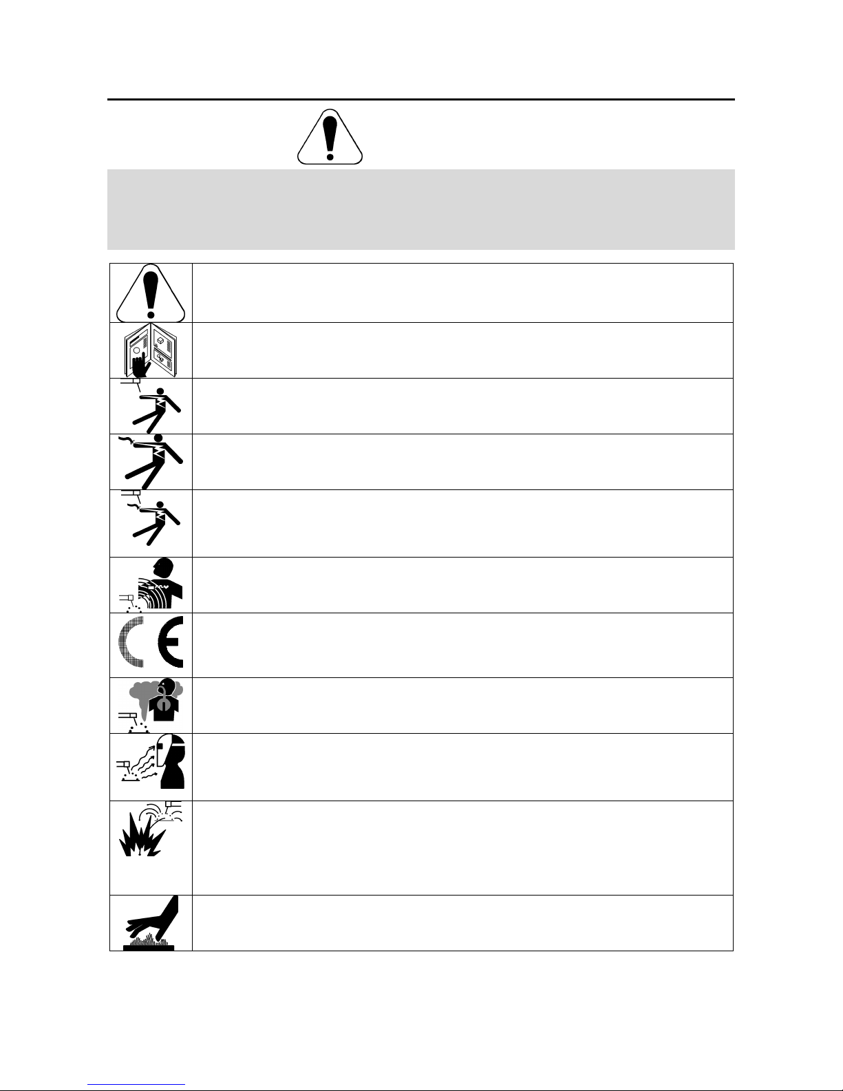
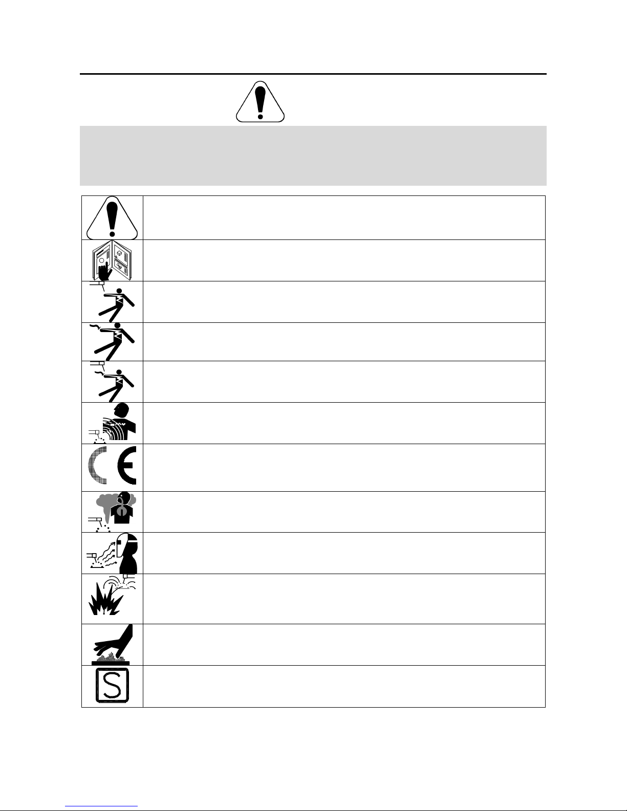
WARNING: This symbol indicates that instructions must be followed to avoid serious personal injury,
loss of life, or damage to this equipment. Protect yourself and others from possible serious injury or
death.
READ AND UNDERSTAND INSTRUCTIONS: Read and understand this manual before operating
this equipment. Arc welding can be hazardous. Failure to follow the instructions in this manual could
cause serious personal injury, loss of life, or damage to this equipment.
ELECTRIC SHOCK CAN KILL: Welding equipment generates high voltages. Do not touch the
electrode, work clamp, or connected work pieces when this equipment is on. Insulate yourself from
the electrode, work clamp, and connected work pieces.
ELECTRICALLY POWERED EQUIPMENT: Turn off input power using the disconnect switch at the
fuse box before working on this equipment. Ground this equipment in accordance with local electrical
regulations.
ELECTRICALLY POWERED EQUIPMENT: Regularly inspect the input, electrode, and work clamp
cables. If any insulation damage exists replace the cable immediately. Do not place the electrode
holder directly on the welding table or any other surface in contact with the work clamp to avoid the
risk of accidental arc ignition.
ELECTRIC AND MAGNETIC FIELDS MAY BE DANGEROUS: Electric current flowing through any
conductor creates electric and magnetic fields (EMF). EMF fields may interfere with some
pacemakers, and welders having a pacemaker shall consult their physician before operating this
equipment.
CE COMPLIANCE: This equipment complies with the European Community Directives.
FUMES AND GASES CAN BE DANGEROUS: Welding may produce fumes and gases hazardous to
health. Avoid breathing these fumes and gases. To avoid these dangers the operator must use
enough ventilation or exhaust to keep fumes and gases away from the breathing zone.
ARC RAYS CAN BURN: Use a shield with the proper filter and cover plates to protect your eyes from
sparks and the rays of the arc when welding or observing. Use suitable clothing made from durable
flame-resistant material to protect you skin and that of your helpers. Protect other nearby personnel
with suitable, non-flammable screening and warn them not to watch the arc nor expose themselves to
the arc.
WELDING SPARKS CAN CAUSE FIRE OR EXPLOSION: Remove fire hazards from the welding
area and have a fire extinguisher readily available. Welding sparks and hot materials from the welding
process can easily go through small cracks and openings to adjacent areas. Do not weld on any
tanks, drums, containers, or material until the proper steps have been taken to insure that no
flammable or toxic vapors will be present. Never operate this equipment when flammable gases,
vapors or liquid combustibles are present.
WELDED MATERIALS CAN BURN: Welding generates a large amount of heat. Hot surfaces and
materials in work area can cause serious burns. Use gloves and pliers when touching or moving
materials in the work area.
SAFETY MARK: This equipment is suitable for supplying power for welding operations carried out in
an environment with increased hazard of electric shock.
Page 6
A
-2
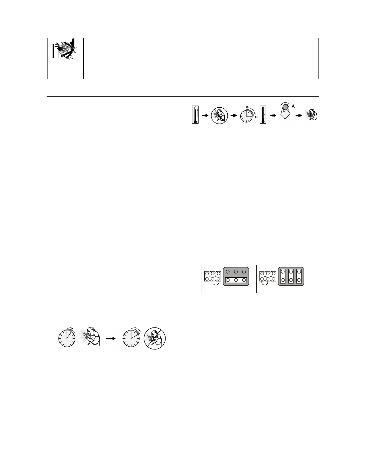
CYLINDER MAY EXPLODE IF DAMAGED: Use only compressed gas cylinders containing the
correct shielding gas for the process used and properly operating regulators designed for the gas and
pressure used. Always keep cylinders in an upright position securely chained to a fixed support. Do
not move or transport gas cylinders with the protection cap removed. Do not allow the electrode,
electrode holder, work clamp or any other electrically live part to touch a gas cylinder. Gas cylinders
must be located away from areas where they may be subjected to physical damage or the welding
process including sparks and heat sources.
Installation and Operator Instructions
Read this entire section before installation or operation
of the machine.
Location and Environment
This machine will operate in harsh environments.
However, it is important that simple preventative
measures are followed to assure long life and reliable
operation:
• Do not place or operate this machine on a surface
with an incline greater than 15° from horizontal.
• Do not use this machine for pipe thawing.
• This machine must be located where there is free
circulation of clean air without restrictions for air
movement to and from the air vents. Do not cover
the machine with paper, cloth or rags when
switched on.
• Dirt and dust that can be drawn into the machine
should be kept to a minimum.
• This machine has a protection rating of IP23. Keep
it dry when possible and do not place it on wet
ground or in puddles.
• Locate the machine away from radio controlled
machinery. Normal operation may adversely affect
the operation of nearby radio controlled machinery,
which may result in injury or equipment damage.
Read the section on electromagnetic compatibility in
this manual.
• Do not operate in areas with an ambient
temperature greater than 40°C.
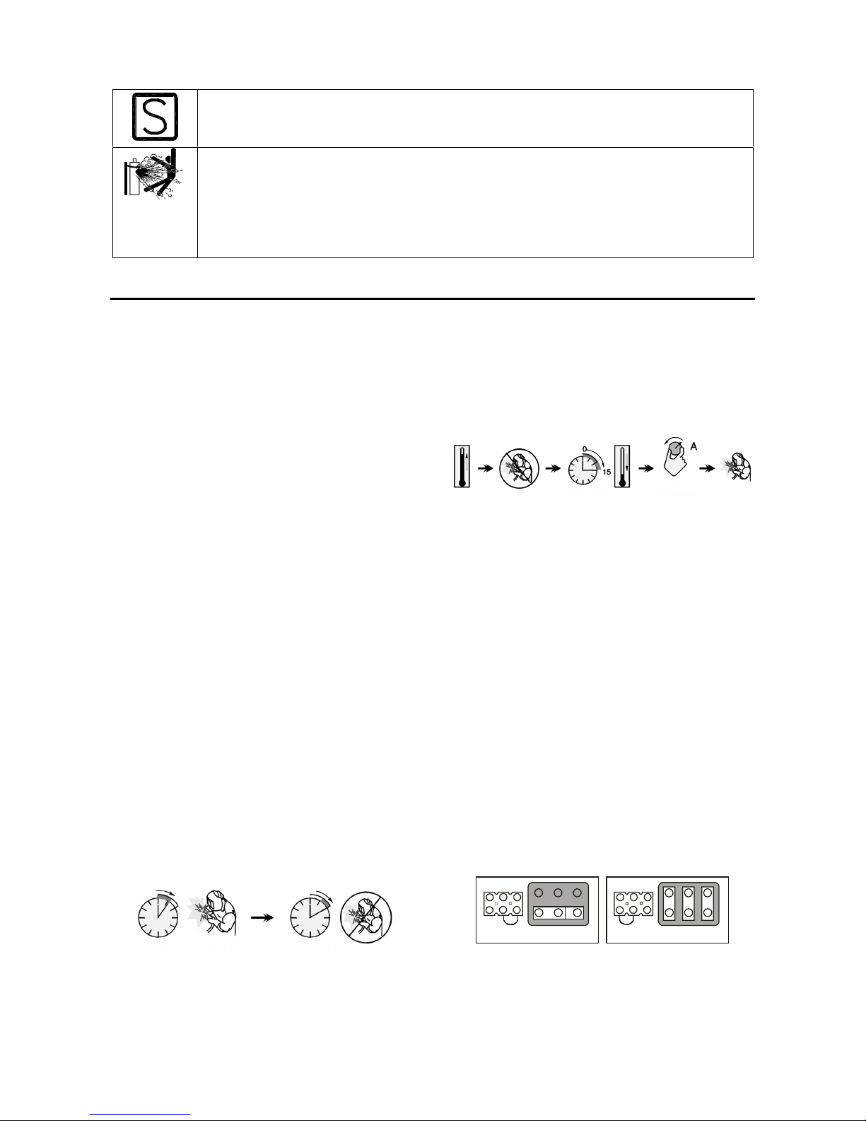
Duty cycle and Overheating
The duty cycle of a welding machine is the percentage of
time in a 10 minute cycle at which the welder can
operate the machine at rated welding current.
Example: 60% duty cycle:
Welding for 6 minutes. Break for 4 minutes.
Excessive extension of the duty cycle will cause the
thermal protection circuit to activate.
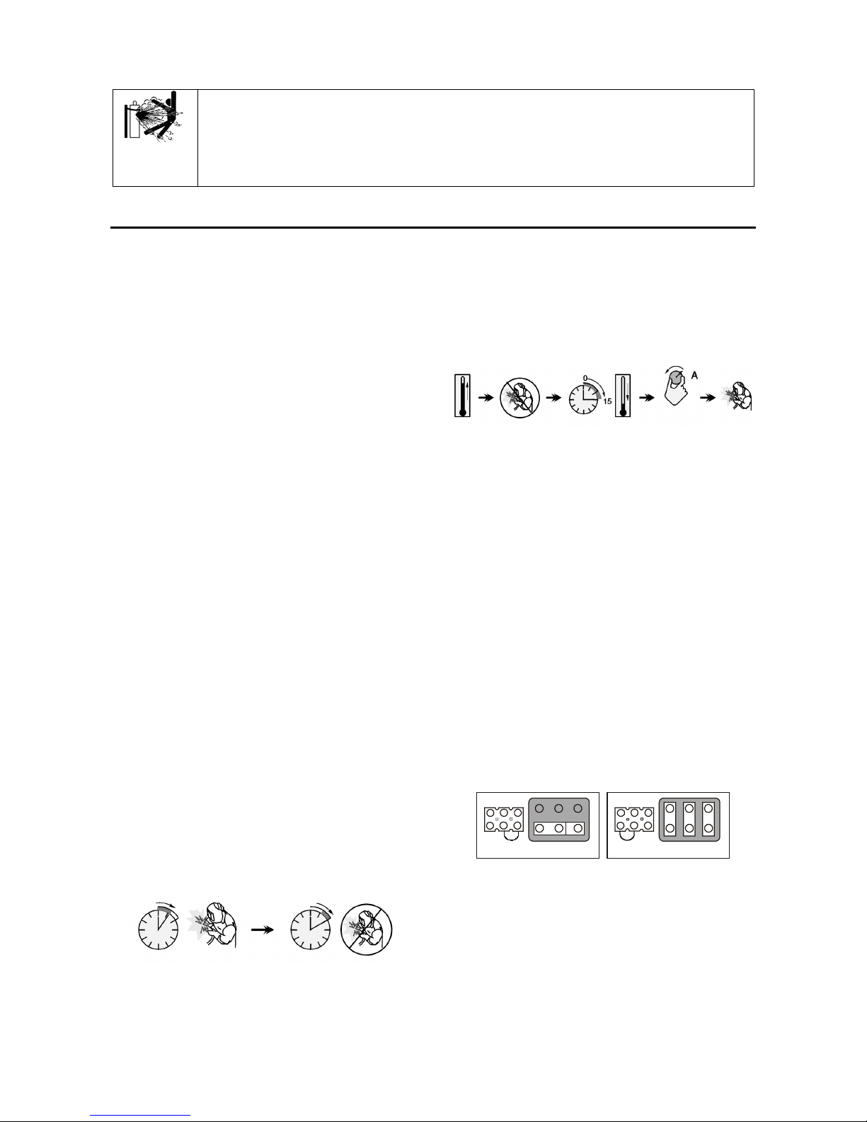
The welding transformer in the machine is protected
from overheating by a thermostat. When the machine is
overheated the output of the machine will turn “OFF“,
and the Thermal Indicator Light will turn “ON“. When the
machine has cooled to a safe temperature the Thermal
Indicator Light will go out and the machine may resume
normal operation. Note: For safety reasons the machine
will not come out of thermal shutdown if the trigger on
the welding gun has not been released.
Minutes or decrease
duty cycle
Input Supply Connection
Installation and mains outlet socket shall be made and
protected according to appropriate rules.
Check the input voltage, phase, and frequency supplied
to this machine before turning it on. Verify the
connection of grounding wires from the machine to the
input source. The allowable input voltages are 3x230V
and 3x400V 50Hz (400V: factory default). For more
information about input supply refer to the technical
specification section of this manual and to the rating
plate of the machine.
If it is necessary to change the input voltage:
• Ensure that the input cable must be disconnected
from the main supply and the machine switched
OFF.
• Remove the big side cover from the machine.
• Reconnect X11 and X12 according to the diagram
below.
X12
400V
X11
X12
230V
X11
• Replace the big side cover.
Make sure that the amount of mains power available
from the input supply is adequate for normal operation of
the machine. The necessary delayed fuse (or circuit
breaker with ”D” characteristic) and cable sizes are
indicated in the technical specification section of this
manual.
Refer to points [1] and [20] of the images below.
Output Connections
Refer to points [8], [10] and [11] of the images below.
Page 7
A
-3
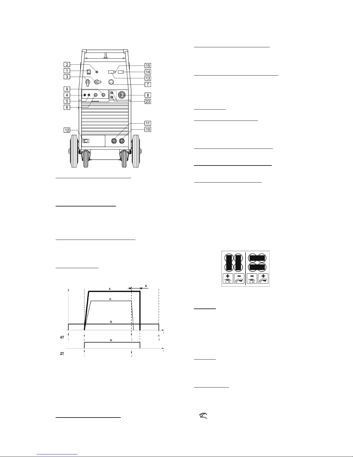
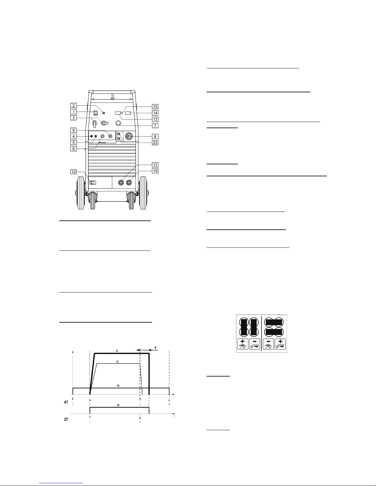
Controls and Operational Features
1. Power Switch and Power Indicator: After input
power is connected and the power switch is turned
on, the indicator will light up to indicate the machine
is ready to weld.
2. Thermal Overload Indicator: This lamp will light up
when the machine is overheated and the output has
been turned off. Leave the machine on to allow the
internal components to cool, when the lamp turns off
normal operation is possible.
3. Welding Voltage Changing Switches: POWERTEC
280C has 2 switches (2 and 10 steps). The
POWERTEC 350C and 420C have 2 switches (3
and 10 steps).
4. Torch Mode Switch: It enables selection of 2-step
or 4-step torch mode. The functionality of 2T/4T
mode is shown in the picture below:
↑
Trigger pressed
↓
Trigger released
A. Welding Current.
B. Burnback time.
C. WFS.
G. Gas.
5. Cold Inch / Gas Purge Switch: This switch enables
wire feeding or gas flow without turning on output
voltage.
6. Wire Feed Slow Run Control Knob: It enables
control of wire feeding speed before welding
beginning, in the range from 0.5 to1.0 of the value
set by the "Wire Feed Speed Control Knob" [7].
7. WFS (Wire Feed Speed) Control Knob: It enables
continuous control of wire feeding speed in the
range from 1.0 to 20m/min with manual mode or
correction of the speed automatically matched by
the machine in the range ±25% at synergic mode.
8. EURO Socket: For connecting welding torch.
9. Burnback Time Control Knob: It enables to obtain
the desired length of electrode wire, which protrudes
from the tip of the torch after ending welding;
adjusting range from 8 to 250ms.
10. Output Socket with High Inductance: For
connecting the return welding cable.
11. Output Socket with Low Inductance: For connecting
the return welding cable.
12. Change Polarity Terminal Strip: It enables welding
voltage polarity selection (+/-), which will be given at
the welding torch (factory default: “+” at the welding
torch).
If necessary changing of welding voltage, you
should:
• Switch off the machine and disconnect it from
mains supply network.
• Take off the terminal strip cover.
• Place the connectors according to the below
drawing.
• Put on the terminal strip cover.
13. Display A: It shows the actual welding current value
(in A), and after finishing welding process, it shows
the average value of the welding current for about
5s. After this time, the display shows the value of
adjusted WFS (in m/min) - for manual mode or
correction of the speed automatically matched by
the machine, in the range 0.75-1.25 at synergic
mode.
14. Display V: It shows the actual value of welding
voltage (in V), and after finishing welding process, it
shows the average value of welding voltage for 5s.
After this time, the display is blank.
15. Work Indicators: These lamps shows the work
mode of the machine:
SYNERGIC
When lit, the machine works in
Synergic mode (automatic mode).
When lit, the machine works in Manual
mode.
Page 8
A
-4
Select the desired work with the "Welding Material
and Gas Mix Choice Knob" [17].
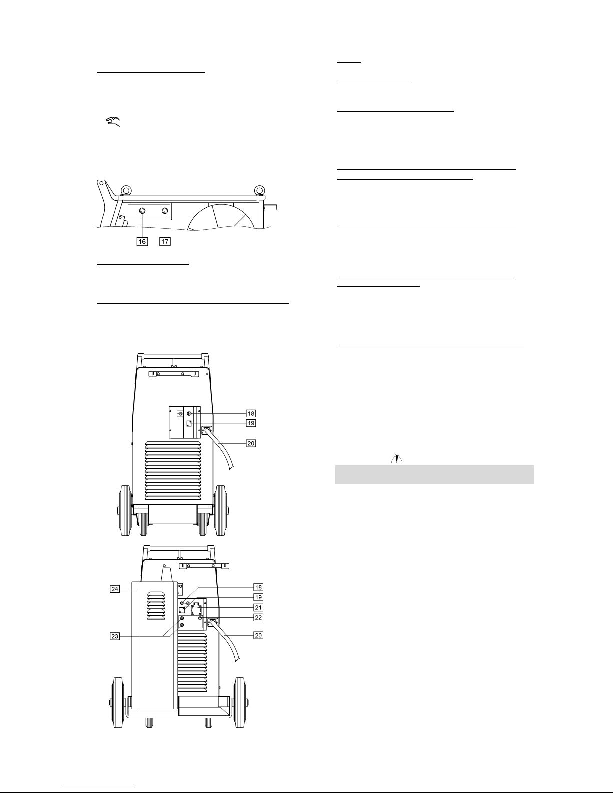
16. Wire Diameter Knob: It allows the choice of the wire
diameter requested for the desired welding process.
This feature is available only for the synergic mode.
17. Welding Material and Gas Mix Choice Knob: This
knob enables the choice of:
• The welded material and its appropriate gas
mixture.
• The manual / synergic work mode.
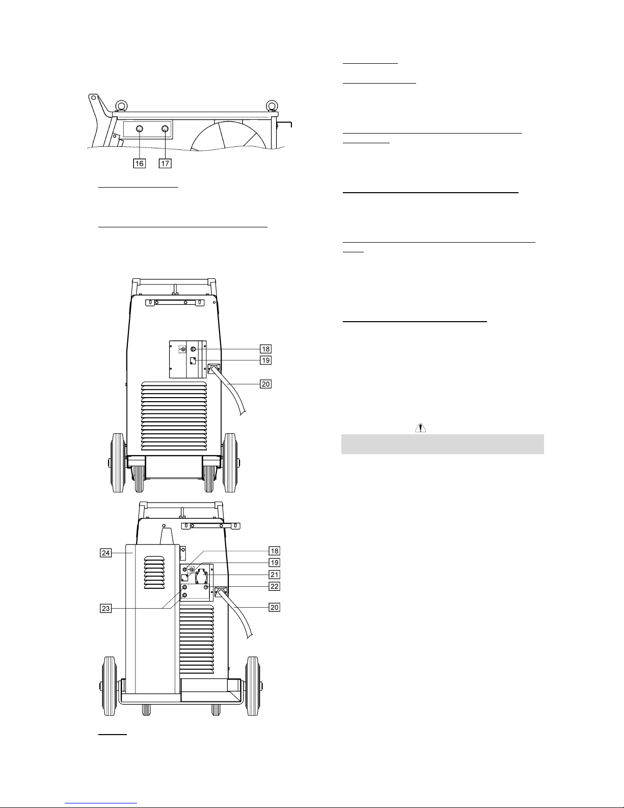
18. Socket: For connecting gas supplying hose.
19. Hole Covered: For CO2 gas heater socket.
20. Power Input Cable: Connect the proper plug to the
input cable to the rated output and according to
appropriate rules. Only qualified personnel shall
connect this plug.
21. Cooler Power Supply Socket (For water cooled
model only): For supplying the cooler unit. The
socket has an intermittent output of 230V, 2.5A and
is protected by the circuit breaker [22]. See point
[24] for more details.
22. Circuit Breaker (For water cooled model only):
Protect the Cooler Power Supply socket [21]. It shut
off the supply power when the current exceed 2.5A.
Press it to restore the supply power.
23. Quick Connect Couplings (For water cooled model
only): For connecting water hose. The welding
torch should be connected to the quick connect
couplings placed on the front panel of the machine.
The cooler [24] should be connected to the quick
connect couplings placed on the rear panel of the
machine.
24. Cooler (For water cooled model only): It refrigerates
the water cooled welding torch. It is automatically
switched on / off by the machine as follows:
• When a weld is started, the Cooler is
automatically switched on.
• When the weld is stopped, the Cooler continues
to run for about 5min., after this time, it is
automatically switched off.
• If the weld is restarted in less than 5min., the
Cooler continues to run.
WARNING
Read and understand the cooler manual before
connecting it to the machine.
Welding Cables Connections
Insert the plug of the ground cable into the socket [10] or
[11]. The other end of this cable connects to the work
piece with the work clamp.
Connect the Euro connector to the welding torch with the
contact tip and torch liner suitable for the wire diameter
and material welded.
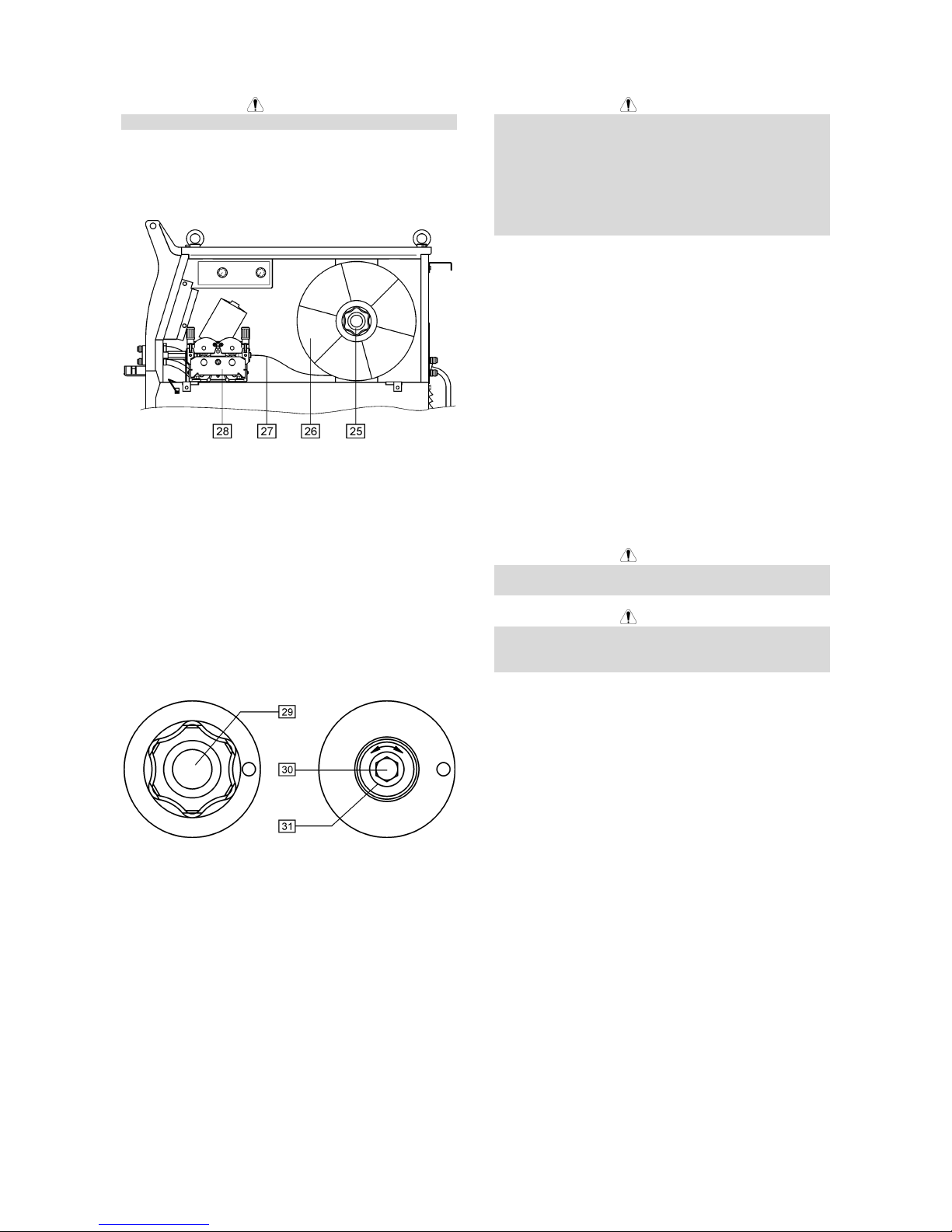
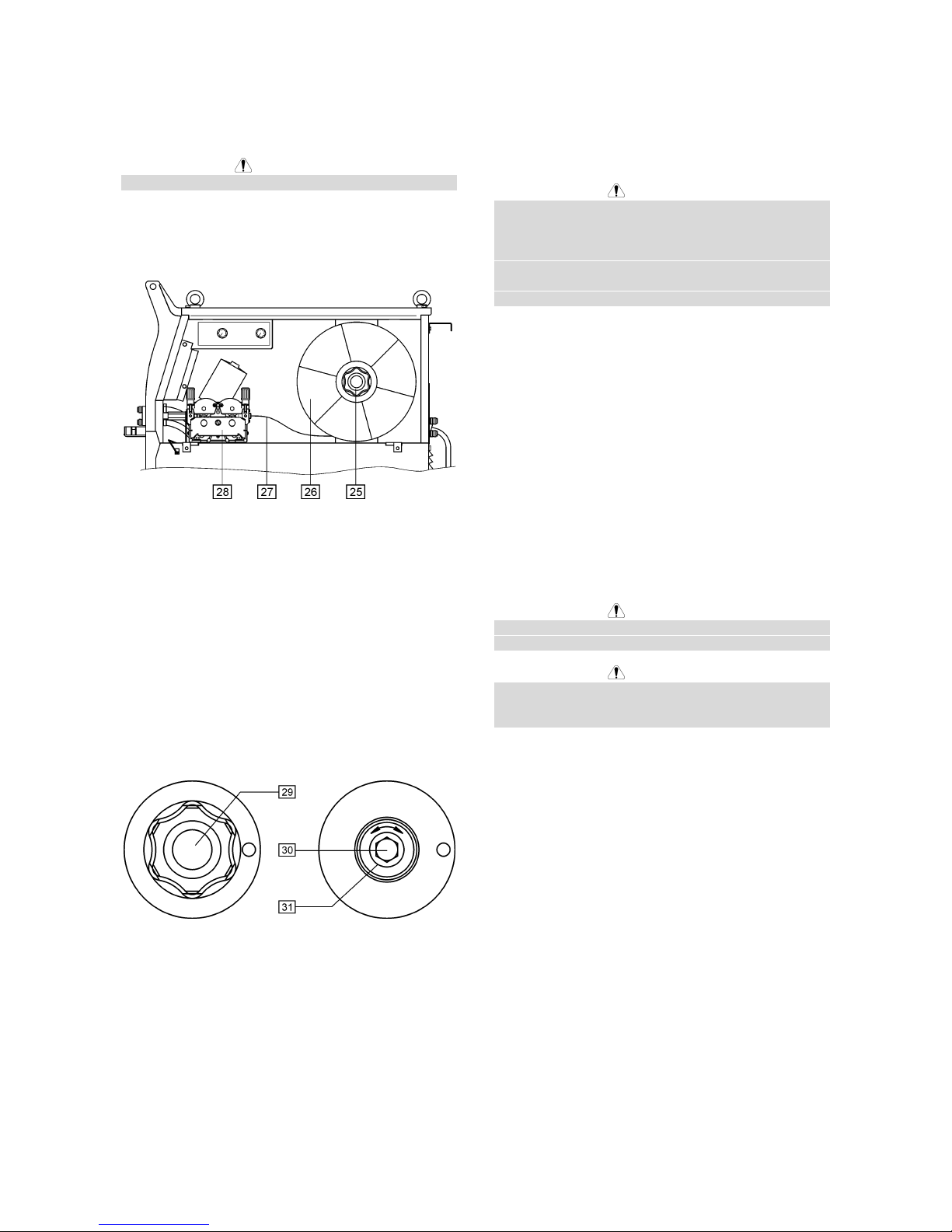
Loading the Electrode Wire
Open the side cover of the machine.
Unscrew the fastening cap of the sleeve.
Load the spool with the wire on the sleeve such that the
spool turns clockwise when the wire is fed into the wire
feeder.
Make sure that the spool locating pin goes into the fitting
hole on the spool.
Screw in the fastening cap of the sleeve.
Put on the wire roll using the correct groove
corresponding to the wire diameter.
Free the end of the wire and cut off the bent end making
sure it has no burr.
Page 9
A
-5
WARNING
Sharp end of the wire can hurt.
Rotate the wire spool clockwise and thread the end of
the wire into the wire feeder as far as the Euro socket.
Adjust force of pressure roll of the wire feeder properly.
25. Sleeve.
26. Wire spool.
27. Electrode wire.
28. Feeding unit.
The machine is designed for wire spools of 15kg
(300mm).
Adjustments of Brake Torque of Sleeve
To avoid spontaneous unrolling of the welding wire the
sleeve is fitted with a brake.
Adjustment is carried by rotation of its screw M10, which
is placed inside of the sleeve frame after unscrewing the
fastening cap of the sleeve.
29. Fastening cap.
30. Adjusting screw M10.
31. Pressing spring.
Turning the screw M10 clockwise increases the spring
tension and you can increase the brake torque.
Turning the screw M10 counterclockwise decreases the
spring tension and you can decrease the brake torque.
After finishing of adjustment, you should screw in the
fastening cap again.
Adjusting of Force of Pressure Roll
Force
Pressure force is adjusted by turning the adjustment nut
clockwise to increase force, counterclockwise to
decrease force.
WARNING
If the roll pressure is too low the roll will slide on the wire.
If the roll pressure is set too high the wire may be
deformed, which will cause feeding problems in the
welding gun. The pressure force should be set properly.
Decrease the pressure force slowly until the wire just
begins to slide on the drive roll and then increase the
force slightly by turning of the adjustment nut by one
turn.
Inserting Electrode Wire into Welding
Torch
Connect the proper welding torch to the Euro socket, the
rated parameters of the torch and of the welding source
shall match.
Switch on the power supply (the main switch [1] in “I”
position).
Remove the gas diffuser and contact tip from the
welding torch.
Set the wire feeding speed in the position of about
10m/min by the WFS knob [7].
Switch the Cold Inch / Gas Purge switch [5] in the
position “Cold Inch” and keep in this position until the
electrode wire leaves the contact tip of the welding torch.
WARNING
Take precaution to keep eyes and hands away from the
end of the torch while feeding wire.
WARNING
Once the wire has finished feeding through the welding
gun turn the machine “OFF“ before replacing to contact
tip and gas diffuser.
Gas Supplying
Connect the gas hose to the gas supplying socket [18]
located on the rear panel of the machine.
Put the gas cylinder on the machine shelf secure it with
the chain.
Take off the safety cap from the shielding gas cylinder
and install the flow regulator on it.
Connect the gas hose of the machine to the regulator
with the clamp band.
Welding with MIG / MAG method in
Manual mode
To begin welding process with MIG/MAG method in
manual mode you should:
• Insert the plug of input supply cable into the main
socket.
• Switch ON the machine with the “Power Switch” [1]
(it should light on).
• Insert the electrode wire into the torch using ”Cold
Inch“ switch [5].
• Check gas flow with ”Gas Purge” switch [5].
• Set knob [17] in Manual position (verify that the
indicator [15] has lit the Manual mode).
• According to selected welding mode and material
thickness set the proper welding voltage with
switches [3] and the wire feeding speed with WFS
Page 10
A
-6
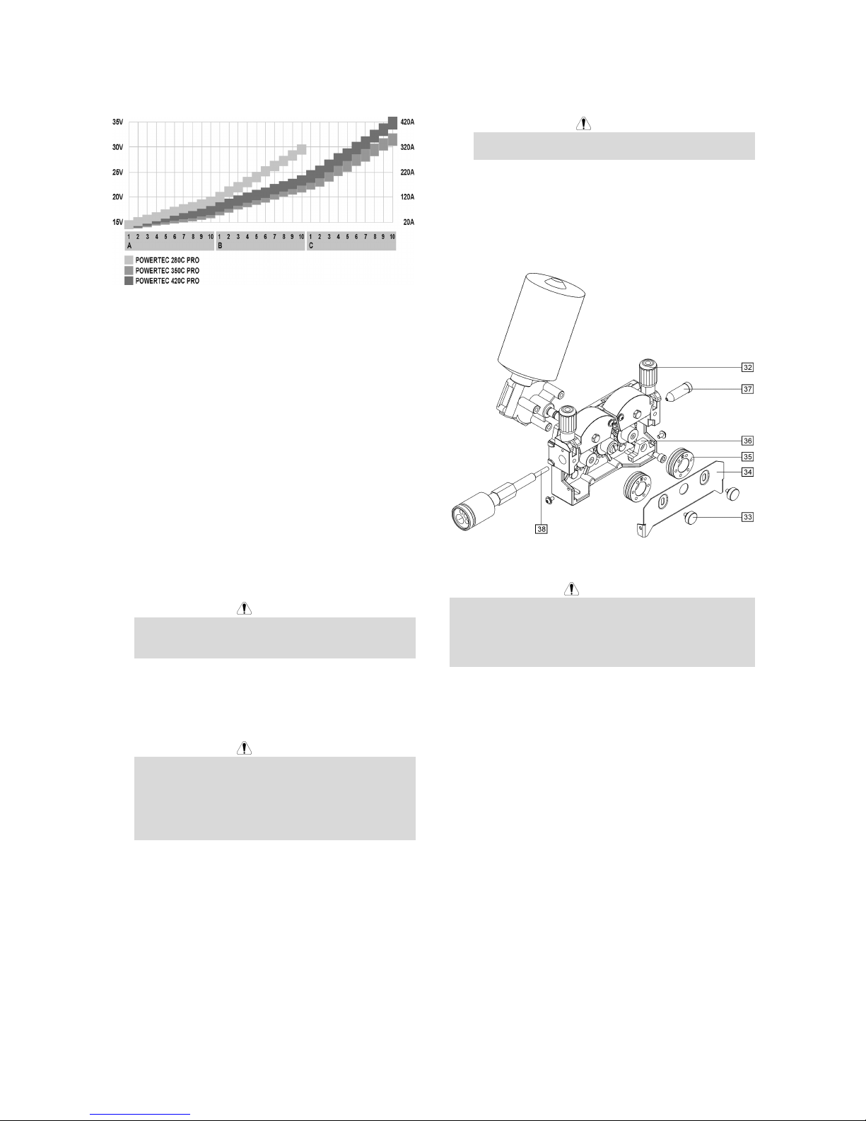
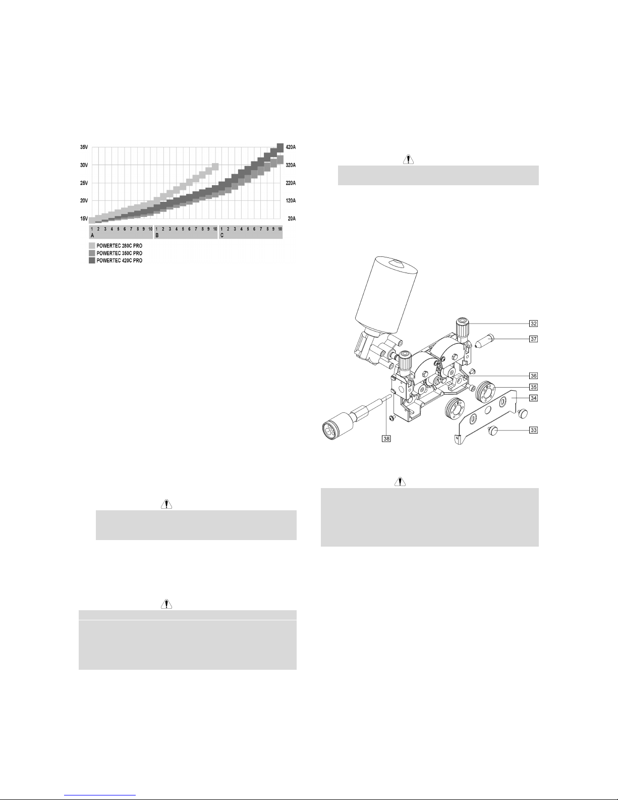
knob [7]. The chart below can be useful for welding
setting selection:
• Obeying the appropriate rules, you can begin to
weld.
Welding with MIG / MAG method in
Synergic (automatic) mode
To begin welding process with MIG/MAG method in
synergic mode you should:
• Insert the plug of input supply cable into the main
socket.
• Switch ON the machine with the “Power Switch” [1]
(it should light on).
• Insert the electrode wire into the torch using ”Cold
Inch“ switch [5].
• Check gas flow with ”Gas Purge” switch [5].
• Set the knob of the choice wire diameter selection
[16] in the position corresponding to the diameter of
the used wire.
• Set the knob of the choice welded material and gas
mixture [17] in the position corresponding to the
used material.
WARNING
If the selected welding process does not have
synergic mode, three horizontal dashes will appear
on the display “A”.
• According to the selected welding mode and
material thickness, set the proper welding voltage
through the "Welding Voltage Changing Switches"
[3].
WARNING
For synergic welding mode the machine
automatically select the proper wire feeding speed
for each position of the "Welding Voltage Changing
Switches" [3]. The automatic speed value can be
adjusted in the range of the ±25% by the WFS
Control Knob [7].
• Obeying the appropriate rules, you can begin to
weld.
Changing Driving Rolls
The machine is equipped with drive rolls for the wire of
1.0 and 1.2mm (factory default). For others wire sizes,
is available the proper drive rolls kit (see chapter
Accessories for ordering the desired kit). Below is the
drive rolls replacement procedure:
• Switch off the machine.
• Release the pressure roll lever [32].
• Unscrew the fastening cap [33].
• Open the protection cover [34].
• Change the drive rolls [35] with the compatible ones
corresponding to the used wire.
WARNING
For wires with the diameter greater than 1.6mm, the
following parts are to be changed:
• The guide tube of the feeding console [36] and
[37].
• The guide tube of the Euro socket [38].
• Replace and tighten the protection cover [34] to the
drive rolls.
• Screw the protection cover by fastening screws [33].
Maintenance
WARNING
For any maintenance or repair operations it is
recommended to contact the nearest technical service
center or Lincoln Electric. Maintenance or repairs
performed by unauthorized service centers or personnel
will null and void the manufacturers warranty.
The frequency of the maintenance operations may vary
in accordance with the working environment where the
machine is placed.
Any noticeable damage should be reported immediately.
Routine maintenance (everyday)
• Check cables and connections integrity. Replace, if
necessary.
• Remove the spatters from the welding gun nozzle.
Spatters could interfere with the shielding gas flow
to the arc.
• Check the welding gun condition: replace it, if
necessary.
• Check condition and operation of the cooling fan.
Keep clean its airflow slots.
Periodic maintenance (every 200 working hours
but not more rarely than once a year)
Perform the routine maintenance and, in addition:
• Keep clean the machine. Using a dry ( and low
pressure) airflow, remove the dust from the external
case and from inside of the cabinet.
• Check and tighten all screws.
Page 11

A
-7
WARNING
Mains supply network must be disconnected from the
machine before each maintenance and service. After
each repair, perform proper tests to ensure safety.
Electromagnetic Compatibility (EMC)
11/04
This machine has been designed in accordance with all relevant directives and standards. However, it may still generate
electromagnetic disturbances that can affect other systems like telecommunications (telephone, radio, and television) or
other safety systems. These disturbances can cause safety problems in the affected systems. Read and understand
this section to eliminate or reduce the amount of electromagnetic disturbance generated by this machine.
This machine has been designed to operate in an industrial area. To operate in a domestic area it is
necessary to observe particular precautions to eliminate possible electromagnetic disturbances. The
operator must install and operate this equipment as described in this manual. If any electromagnetic
disturbances are detected the operator must put in place corrective actions to eliminate these disturbances
with, if necessary, assistance from Lincoln Electric.
Before installing the machine, the operator must check the work area for any devices that may malfunction because of
electromagnetic disturbances. Consider the following.
• Input and output cables, control cables, and telephone cables that are in or adjacent to the work area and the
machine.
• Radio and/or television transmitters and receivers. Computers or computer controlled equipment.
• Safety and control equipment for industrial processes. Equipment for calibration and measurement.
• Personal medical devices like pacemakers and hearing aids.
• Check the electromagnetic immunity for equipment operating in or near the work area. The operator must be sure
that all equipment in the area is compatible. This may require additional protection measures.
• The dimensions of the work area to consider will depend on the construction of the area and other activities that are
taking place.
Consider the following guidelines to reduce electromagnetic emissions from the machine.
• Connect the machine to the input supply according to this manual. If disturbances occur if may be necessary to take
additional precautions such as filtering the input supply.
• The output cables should be kept as short as possible and should be positioned together. If possible connect the
work piece to ground in order to reduce the electromagnetic emissions. The operator must check that connecting
the work piece to ground does not cause problems or unsafe operating conditions for personnel and equipment.
• Shielding of cables in the work area can reduce electromagnetic emissions. This may be necessary for special
applications.
Page 12
A
-8
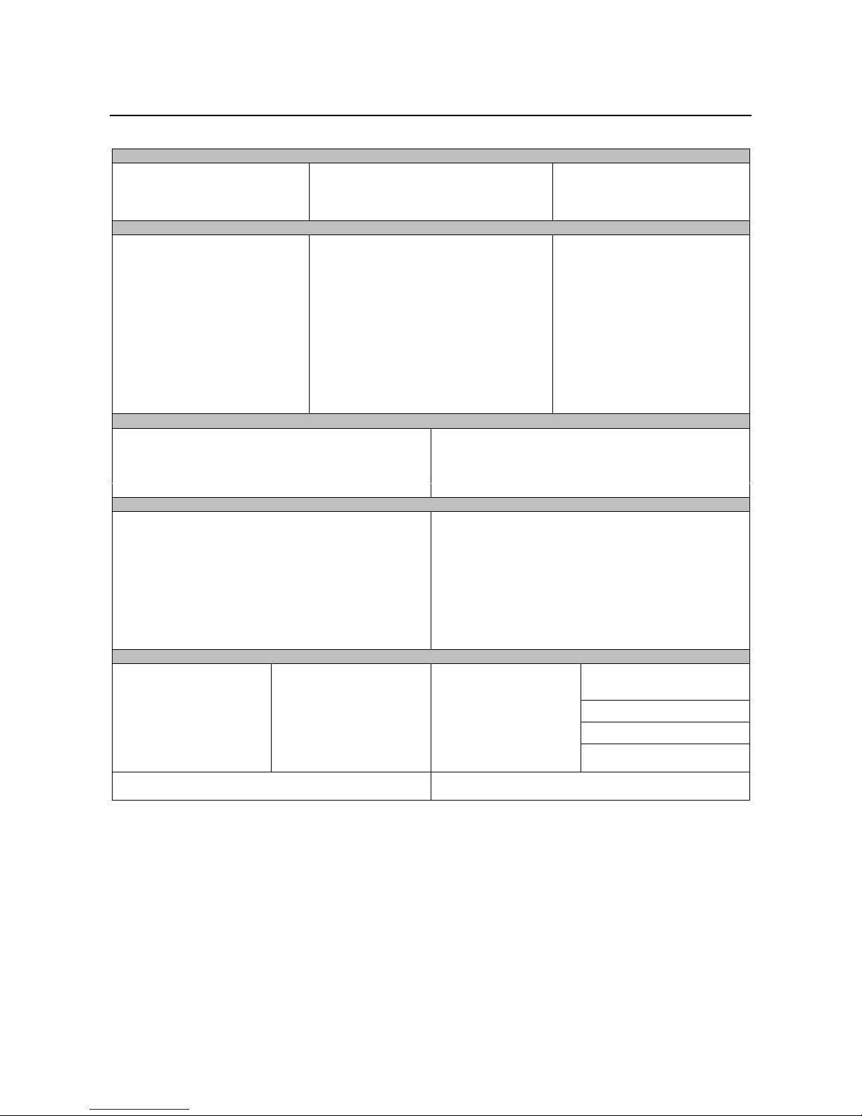
Technical Specifications
POWERTEC 280C, 350C & 420C PRO:
INPUT
Input Power at Rated Output
280C PRO:
12 kVA @ 40% Duty Cycle
350C PRO:
16 kVA @ 40% Duty Cycle
Input Voltage
230 / 400V ± 10%
Three Phase
420C PRO:
21 kVA @ 40% Duty Cycle
Frequency
50 Hertz (Hz)
RATED OUTPUT AT 40°C
Duty Cycle
(
Based on a 10 min. period)
Output Current Output Voltage
280C PRO:
40%
60%
100%
280A
230A
175A
28.0 Vdc
25.5 Vdc
22.8 Vdc
350C PRO:
40%
60%
100%
350A
285A
220A
31.5 Vdc
28.2 Vdc
25.0 Vdc
420C PRO:
40%
60%
100%
420A
345A
265A
35.0 Vdc
31.3 Vdc
27.3 Vdc
OUTPUT RANGE
Welding Current Range Maximum Open Circuit Voltage
280C PRO:
30A - 280A
280C PRO:
39 Vdc
350C PRO:
30A - 350A
350C PRO:
42 Vdc
420C PRO:
30A - 420A
420C PRO:
49 Vdc
RECOMMENDED INPUT CABLE AND FUSE SIZES
Fuse or Circuit Breaker Size Input Power Cable
280C PRO:
32A (for 230V) Superlag
20A (for 400V) Superlag
280C PRO:
4 Conductor, 4mm
2
350C PRO:
40A (for 230V) Superlag
25A (for 400V) Superlag
350C PRO:
4 Conductor, 4mm
2
420C PRO:
63A (for 230V) Superlag
32A (for 400V) Superlag
420C PRO:
4 Conductor, 6mm
2
PHYSICAL DIMENSIONS
Weight
280C PRO:
142 kg
350C PRO:
147 kg
420C PRO:
157 kg
Height
910 mm
Width
565 mm
700 mm
(water version)
Length
1030 mm
420C PRO:
(water)
183 kg
Operating Temperature
-10°C to +40°C
Storage Temperature
-25°C to +55°C
Page 13
B-1
Sicurezza
11/04
AVVERTENZA
Questa macchina deve essere impiegata solo da personale qualificato. Assicuratevi che tutte le procedure di
installazione, impiego, manutenzione e riparazione vengano eseguite solamente da persone qualificate. Leggere e
comprendere questo manuale prima di mettere in funzione la macchina. La mancata osservanza delle istruzioni di
questo manuale può provocare seri infortuni, anche mortali, alle persone, o danni alla macchina. Leggere e
comprendere le spiegazioni seguenti sui simboli di avvertenza. La Lincoln Electric non si assume alcuna responsabilità
per danni conseguenti a installazione non corretta, incuria o impiego in modo anormale.
AVVERTENZA: Questo simbolo indica che occorre seguire le istruzioni per evitare seri infortuni,
anche mortali, alle persone o danni a questa macchina. Proteggete voi stessi e gli altri dalla
possibilità di seri infortuni anche mortali.
LEGGERE E COMPRENDERE LE ISTRUZIONI: Leggere e comprendere questo manuale prima di
far funzionare la macchina. La saldatura ad arco può presentare dei rischi. La mancata osservanza
delle istruzioni di questo manuale può provocare seri infortuni, anche mortali, alle persone o danni alla
macchina.
LA FOLGORAZIONE ELETTRICA E’ MORTALE: Le macchine per saldatura generano tensioni
elevate. Non toccate l’elettrodo, il morsetto di massa o pezzi da saldare collegati alla macchina
quando la macchina è accesa. Mantenetevi isolati elettricamente da elettrodo, morsetto e pezzi
collegati a questo.
MACCHINA CON ALIMENTAZIONE ELETTRICA: Togliere l’alimentazione con l’interruttore ai fusibili
prima di svolgere operazioni su questa macchina. Mettere la macchina a terra secondo le normative
vigenti.
MACCHINA CON ALIMENTAZIONE ELETTRICA: Ispezionare periodicamente i cavi di
alimentazione, all’elettrodo e al pezzo. Se si riscontrano danni all’isolamento sostituire
immediatamente il cavo. Non posare la pinza portaelettrodo direttamente sul banco di saldatura o
qualsiasi altra superficie in contatto con il morsetto di massa per evitare un innesco involontario
dell’arco.
I CAMPI ELETTRICI E MAGNETICI POSSONO ESSERE PERICOLOSI: Il passaggio di corrente
elettrica in un conduttore produce campi elettromagnetici. Questi campi possono interferire con alcuni
cardiostimolatori (“pacemaker”) e i saldatori con un cardiostimolatore devono consultare il loro medico
su possibili rischi prima di impiegare questa macchina.
CONFORMITÀ CE: Questa macchina è conforme alle Direttive Europee.
FUMI E GAS POSSONO ESSERE PERICOLOSI: La saldatura può produrre fumi e gas dannosi alla
salute. Evitate di respirare questi fumi e gas. Per evitare il pericolo l’operatore deve disporre di una
ventilazione o di un'estrazione di fumi e gas che li allontanino dalla zona in cui respira.
I RAGGI EMESSI DALL’ARCO BRUCIANO: Usate una maschera con schermatura adatta a
proteggervi gli occhi da spruzzi e raggi emessi dall’arco mentre saldate o osservate la saldatura.
Indossare indumenti adatti in materiale resistente alla fiamma per proteggere il corpo, sia vostro che
dei vostri aiutanti. Le persone che si trovano nelle vicinanze devono essere protette da schermature
adatte, non infiammabili, e devono essere avvertite di non guardare l’arco e di non esporvisi.
GLI SPRUZZI DI SALDATURA POSSONO PROVOCARE INCENDI O ESPLOSIONI: Allontanare
dall'area di saldatura quanto può prendere fuoco e tenere a portata di mano un estintore. Gli spruzzi
o altri materiali ad alta temperatura prodotti dalla saldatura attraversano con facilità eventuali piccole
aperture raggiungendo le zone vicine. Non saldare su serbatoi, bidoni, contenitori o altri materiali fino
a che non si sia fatto tutto il necessario per assicurarsi dell'assenza di vapori infiammabili o nocivi.
Non impiegare mai questa macchina se vi è presenza di gas e/o vapori infiammabili o combustibili
liquidi.
I MATERIALI SALDATI BRUCIANO: Il processo di saldatura produce moltissimo calore. Ci si può
bruciare in modo grave con le superfici e materiali caldi della zona di saldatura. Impiegare guanti e
pinze per toccare o muovere materiali nella zona di saldatura.
Page 14
B-2
MARCHIO DI SICUREZZA: Questa macchina è adatta a fornire energia per operazioni di saldatura
svolte in ambienti con alto rischio di folgorazione elettrica.
LE BOMBOLE POSSONO ESPLODERE SE SONO DANNEGGIATE: Impiegate solo bombole
contenenti il gas compresso adatto al processo di saldatura utilizzato e regolatori di flusso, funzionanti
regolarmente, progettati per il tipo di gas e la pressione in uso. Le bombole vanno tenute sempre in
posizione verticale e assicurate con catena ad un sostegno fisso. Non spostate le bombole senza il
loro cappello di protezione. Evitate qualsiasi contatto dell’elettrodo, della sua pinza, del morsetto di
massa o di ogni altra parte in tensione con la bombola del gas. Le bombole gas vanno collocate
lontane dalle zone dove possano restare danneggiate dal processo di saldatura con relativi spruzzi e
da fonti di calore.
Installazione e Istruzioni Operative
Leggere tutta questa sezione prima di installare e
impiegare la macchina.
Collocazione e ambiente
Questa macchina è in grado di funzionare in ambienti
difficili. E’ comunque importante seguire delle semplici
misure di prevenzione per garantirne una lunga durata e
un funzionamento affidabile.
• Non collocare o impiegare la macchina su superfici
inclinate più di 15° rispetto all’orizzontale.
• Non usare questa macchina per sgelare tubi.
• La macchina va collocata ove vi sia una circolazione
di aria pulita senza impedimenti al suo movimento in
entrata e uscita dalle feritoie. Non coprire la
macchina con fogli di carta, panni o stracci quando
è accesa.
• Tenere al minimo polvere e sporco che possano
entrare nella macchina.
• Questa macchina ha una protezione di grado IP23.
Tenetela più asciutta possibile e non posatela su
suolo bagnato o dentro pozzanghere.
• Disponete la macchina lontana da macchinari
controllati via radio. Il suo funzionamento normale
può interferire negativamente sul funzionamento di
macchine controllate via radio poste nelle vicinanze,
con conseguenze di infortuni o danni materiali.
Leggete la sezione sulla compatibilità
elettromagnetica di questo manuale.
• Non impiegate la macchina in zone ove la
temperatura ambiente supera i 40°C.
Fattore di Intermittenza e
Surriscaldamento
Il fattore di intermittenza di una saldatrice è la
percentuale di tempo su un periodo di 10 minuti durante
la quale si può far funzionare la macchina alla corrente
nominale corrispondente.
Esempio: Fattore di intermittenza 60%:
Saldatura per 6 minuti. Interruzione per 4 minuti.
Il superamento del fattore di intermittenza provoca
l’attivazione del circuito di protezione termica.
Un termostato protegge dal surriscaldamento il
trasformatore di saldatura. Se la macchina si
surriscalda, l’uscita viene interrotta e si accende la spia
dell’indicatore termico. Una volta raffreddata la
macchina a temperatura di sicurezza, la spia indicatore
termico si spegne e la macchina può riprendere il
funzionamento normale. Nota: Per motivi di sicurezza la
macchina non esce dall’arresto “termico” se non si è
rilasciato il pulsante torcia.
Minuti o ridurre il
fattore di
intermittenza
Collegamento all’alimentazione
L’installazione e la presa dalla rete di alimentazione
devono essere realizzate e protette secondo la
normativa vigente.
Prima di accendere la macchina verificare tensione, fasi
e frequenza dell’alimentazione. Controllare il
collegamento dei cavi di messa a terra fra la macchina e
la sua alimentazione. Tensioni di alimentazione
ammissibili: 3x230V e 3x400V 50Hz (come spedito dalla
fabbrica: 400V). Per ulteriori informazioni
sull’alimentazione fare riferimento alla Sezione
Specifiche tecniche del manuale e alla targhetta dati
della macchina.
Nel caso si debba modificare la tensione di
alimentazione:
• Assicurarsi che il cavo di alimentazione sia staccato
dalla presa di rete e che la macchina sia SPENTA
(interruttore su “0”).
• Rimuovere il pannello grande dal fianco della
macchina.
• Ricollegare X11 e X12 come da schema qui sotto.
X12
400V
X11
X12
230V
X11
• Ricollocare in posto sul fianco il pannello grande.
Assicuratevi che l’alimentazione fornisca una potenza
sufficiente per il funzionamento normale della macchina.
Nella sezione “Specifiche tecniche” di questo manuale
sono indicate le dimensioni necessarie per i fusibili
ritardati (o interruttori automatici con caratteristica tipo
Page 15
B-3
"D") e cavi.
Riferirsi ai punti [1] e [20] delle immagini sotto.
Collegamenti in uscita
Riferirsi ai punti [8], [10] e [11] delle immagini sotto.
Comandi e possibilità operative
1. Interruttore generale e spia accensione: Dopo che
ci si è collegati alla alimentazione elettrica e si è
acceso l’interruttore generale, la spia si accende
indicando che la macchina è pronta a saldare.
2. Spia indicatrice di sovraccarico termico: Questa
luce si accende quando la macchina si surriscalda e
l’uscita viene interrotta. Lasciare accesa la
macchina per permettere il raffreddamento dei
componenti interni; quando la spia si spegne è
possibile riprendere il funzionamento normale.
3. Commutatori della tensione di saldatura: Il
POWERTEC 280C ha 2 commutatori (2 e 10 scatti).
I POWERTEC 350C e 420C hanno 2 commutatori
(3 e 10 scatti).
4. Commutatore del Modo pulsante Torcia: Permette
di selezionare fra modo torcia a 2 tempi o a 4 tempi.
Il disegno qui sotto mostra il sistema di
funzionamento a 2T/4T:
↑
Pulsante premuto
↓
Pulsante rilasciato
A. Corrente di saldatura.
B. Tempo di bruciatura filo.
C. WFS (velocità filo).
G. Gas.
5. Commutatore Filo Freddo / Spurgo Gas: Il
commutatore permette avanzamento del filo o
flusso del gas senza avere tensione in uscita.
6. Manopola comando avanzamento filo freddo:
Permette di regolare la velocità del filo, prima
dell’inizio della saldatura, fra 0.5 e 1.0 rispetto al
valore impostato con la manopola WFS [7].
7. Manopola di regolazione velocità filo (WFS - Wire
Feed Speed): Permette la regolazione continua
della velocità filo nella gamma fra 1.0 e 20m/min in
modo manuale, o la correzione entro un ±25% di
quella correlata automaticamente dalla macchina in
modo sinergico.
8. Presa EURO: Per collegare la torcia.
9. Manopola di regolazione del tempo di bruciatura filo:
Permette di ottenere la lunghezza desiderata di filo
elettrodo che resta sporgente dalla punta della
torcia a fine saldatura; gamma di regolazione da 8 a
250ms.
10. Presa di uscita ad alta induttanza: Per il
collegamento del cavo massa di ritorno.
11. Presa di uscita a bassa induttanza: Per il
collegamento del cavo massa di ritorno.
12. Banco terminali per cambio polarità: Permette di
scegliere la polarità (+/-) di saldatura da dare alla
torcia (fornito dalla fabbrica: “+” alla torcia).
Se è necessario cambiare la polarità di saldatura,
occorre:
• Spegnere la macchina e staccarla dalla rete di
alimentazione.
• Togliere il coperchio del banco terminali.
• Disporre i connettori come indicato nel disegno
qui sotto.
• Rimettere il coperchio sul banco terminali.
13. Display A: Indica il valore effettivo della corrente di
saldatura (in A), ed al termine del processo di
saldatura indica il valore medio della corrente
stessa per circa 5s. Dopo questo periodo, sul
display compare, in modo manuale, il valore della
WFS (in m/min) come regolato, oppure, in modo
sinergico, la correzione fra 0.75 -1.25 della velocità
correlata automaticamente dalla macchina.
14. Display V: Indica il valore effettivo della tensione di
saldatura (in V) e, al termine della saldatura, indica
il valore medio di questa tensione per altri 5s.
Passati i 5s, il display resta vuoto.
Page 16
B-4
15. Indicatori del modo di lavoro: Indicazioni luminose
del modo di lavoro della macchina:
SYNERGIC
Acceso quando la macchina lavora in
modo Sinergico (modo automatico).
Acceso quando la macchina lavora in
modo Manuale.
Selezionare il modo di lavoro desiderato mediante
la manopola "Scelta del Materiale e della Miscela
Gas" [17].
16. Manopola Diametro Filo: Permette la scelta del
diametro filo richiesto per il procedimento
desiderato. Funziona soltanto nel modo sinergico.
17. Manopola Scelta del Materiale e della Miscela Gas:
Permette di scegliere:
• I materiali saldati e la miscela gas appropriata
per questi.
• Modo di lavoro manuale / sinergico.
18. Presa: Per collegamento del tubo del gas in arrivo.
19. Foro con coperchio: Per eventuale presa per il
riscaldamento del gas CO2.
20. Cavo di alimentazione elettrica: Collegare al cavo
di alimentazione una spina adeguata alle
caratteristiche previste seguendo le prescrizioni
della normativa. Soltanto personale qualificato può
effettuare il collegamento.
21. Presa di alimentazione elettrica del refrigeratore
(solo modello raffreddato ad acqua): Alimenta il
refrigeratore. La presa dà un’uscita intermittente a
230V, 2.5A ed è protetta dall’interruttore [22]. Altri
dettagli al punto [24].
22. Interruttore (solo modello raffreddato ad acqua):
Protegge la presa di alimentazione refrigeratore
[21]. Interrompe l’alimentazione se la corrente
supera 2.5A. Premerlo per ridare l’alimentazione.
23. Attacchi per collegamento rapido (solo modello
raffreddato ad acqua): Collegamento tubo acqua.
La torcia va collegata agli attacchi rapidi posti sul
pannello frontale della macchina. Il refrigeratore
[24] va collegato agli attacchi rapidi posti sul
pannello posteriore della macchina.
24. Refrigeratore (solo modello raffreddato ad acqua):
Raffredda ad acqua la torcia di questo tipo. Viene
acceso / spento automaticamente dalla macchina
come segue:
• Acceso automaticamente quando la saldatura
inizia.
• All’arresto della saldatura il refrigeratore
continua a funzionare per circa 5min., dopo i
quali si spegne automaticamente.
• Se si ricomincia a saldare entro i 5min. il
refrigeratore resta in funzione.
AVVERTENZA
Leggere e comprendere il manuale del refrigeratore
prima di collegarlo alla macchina.
Collegamento dei cavi di saldatura
Inserire la spina del cavo massa nella presa [10] o [11].
L’altra estremità del cavo è collegata al pezzo mediante
il morsetto apposito.
Collegare il connettore EURO alla torcia munita di punta
di contatto e guaina adatte al diametro filo e al materiale
da saldare.
Caricamento del filo elettrodo
Aprire il coperchio laterale della macchina.
Svitare il coperchietto di fissaggio dell’adattatore.
Caricare sull’adattatore la bobina con il filo in modo tale
che la bobina giri in senso orario quando il filo avanza
nel trainafilo.
Verificate che il perno di posizionamento bobina
sull’adattatore si impegni nel foro apposito sulla bobina.
Riavvitare il coperchietto di fissaggio dell’adattatore.
Applicate il rullo trainafilo che presenta la scanalatura
Page 17
B-5
corrispondente al diametro del filo.
Liberate l’estremità del filo e tagliatene via la parte
piegata accertando che non restino sfrangiature.
AVVERTENZA
L’estremità appuntita del filo può ferire.
Ruotate la bobina filo in senso orario ed inserite
l’estremità del filo nel trainafilo fino alla presa Euro.
Regolate bene la pressione del rullo folle nel trainafilo.
25. Adattatore.
26. Bobina filo.
27. Filo elettrodo.
28. Gruppo trainafilo.
La macchina è progettata per l’impiego di bobine da
15kg (300mm).
Regolazione della coppia frenante
dell’adattatore
L’adattatore è munito di un freno che evita lo
srotolamento spontaneo del filo.
La regolazione si effettua ruotando la vite M10, collocata
dentro il telaio dell’adattatore (dopo aver svitato il
coperchietto di fissaggio dell’adattatore).
29. Coperchietto di fissaggio.
30. Vite M10 di regolazione.
31. Molla di compressione.
Ruotando la vite M10 in senso orario si comprime di più
la molla e si aumenta la coppia frenante.
Ruotando la vite M10 in senso antiorario si scarica la
molla e si diminuisce la coppia frenante.
Completata la regolazione ricordarsi di riavvitare il
coperchietto di fissaggio.
Regolazione della pressione del rullo
folle
La pressione sul filo si regola ruotando il dado di
regolazione, in senso orario per aumentarla, antiorario
per diminuirla.
AVVERTENZA
Se la pressione del rullo è troppo bassa, il rullo slitterà
su filo. Se la pressione è eccessiva il filo può deformarsi
provocando problemi di avanzamento nella torcia.
Regolate la pressione con precisione. Diminuitela
lentamente fino a che il filo comincia appena a scivolare
sul rullo motore, e poi riaumentatela un po’ dando un
solo giro in più al dado.
Inserimento del filo elettrodo nella
torcia di saldatura
Collegare alla presa Euro la torcia di saldatura adatta; i
parametri nominali di torcia e generatore devono essere
compatibili.
Accendere la macchina (interruttore generale [1] su “I”).
Rimuovere dalla torcia il diffusore gas e la punta di
contatto.
Impostare la velocità di avanzamento filo su circa
10m/min mediante la manopola WFS [7].
Disporre il commutatore Filo freddo / Spurgo Gas [5] su
“Filo freddo” (Cold Inch) e tenercelo fino a che il filo
elettrodo fuoriesce dalla punta di contatto della torcia.
AVVERTENZA
Mentre il filo avanza fare attenzione a tenere mani ed
occhi lontani dalla punta della torcia.
AVVERTENZA
Completato il passaggio del filo attraverso la torcia
spegnere la macchina prima di rimettere sulla torcia la
punta di contatto e il diffusore gas.
Alimentazione del gas
Collegare il tubo gas alla presa gas [18] collocata sul
pannello posteriore della macchina.
Porre la bombola gas sulla piattaforma di cui è munita la
macchina e assicurarla con la catena.
Togliere il coperchio di sicurezza della bombola e
installare su questa il regolatore di flusso.
Collegare al regolatore il tubo gas in arrivo alla
macchina, bloccandolo con la fascetta.
Saldatura con metodo MIG / MAG in
modo Manuale
Per iniziare a saldare in MIG/MAG in modo manuale
occorre:
• Inserire la spina del cavo di alimentazione nella
presa di rete.
• Accendere la macchina con l’interruttore generale
[1] (che si deve illuminare).
• Inserire nella torcia il filo elettrodo portando il
commutatore [5] su ”Cold Inch“.
• Controllare il flusso gas con il commutatore [5] su
”Gas Purge”.
Page 18
B-6
• Mettere la manopola [17] sulla posizione “Manuale”
(verificare che sull’indicatore [15] si sia acceso il
modo Manuale).
• Impostare con i commutatori [3] la tensione di
saldatura e con la manopola WFS [7] la velocità filo,
in funzione del modo di saldatura scelto e dello
spessore del materiale. Il diagramma qui sotto può
risultare utile per la scelta dell’impostazione:
• Si può iniziare a saldare nel rispetto delle normative
e prescrizioni.
Saldatura con metodo MIG / MAG in
modo Sinergico (automatico)
Per iniziare a saldare in MIG/MAG in modo sinergico
occorre:
• Inserire la spina del cavo di alimentazione nella
presa di rete.
• Accendere la macchina con l’interruttore generale
[1] (che si deve illuminare).
• Inserire nella torcia il filo elettrodo portando il
commutatore [5] su ”Cold Inch“.
• Controllare il flusso gas con il commutatore [5] su
”Gas Purge”.
• Posizionare la manopola di selezione diametro filo
[16] sul punto corrispondente al diametro del filo in
uso.
• Posizionare la manopola di scelta del materiale e
della miscela gas [17] nel punto corrispondente al
materiale in uso.
AVVERTENZA
Se il procedimento selezionato non prevede il modo
sinergico, compariranno tre lineette orizzontali sul
display “A”.
• Impostare con i “Commutatori della tensione di
saldatura" [3] la tensione di saldatura giusta in
funzione del modo di saldatura scelto e dello
spessore del materiale.
AVVERTENZA
Nel modo di saldatura sinergico la macchina sceglie
automaticamente la velocità di avanzamento filo adatta
per ogni posizione dei "Commutatori della tensione di
saldatura" [3]. Questo valore automatico della velocità
può essere variato di un ±25% mediante la manopola di
regolazione velocità filo (WFS) [7].
• Si può iniziare a saldare nel rispetto delle normative
e prescrizioni.
Cambio dei Rulli di traino
La macchina viene fornita dalla fabbrica con rulli di traino
per filo di 1,0 e 1,2mm. Per fili di altro diametro, sono
disponibili dei kit rulli appositi, (vedi capitolo “Accessori”
per ordinare il kit desiderato). Segue la procedura di
sostituzione rulli di traino:
• Spegnere la macchina.
• Allentare la leva di messa in pressione rullo [32].
• Svitare i bulloni di fissaggio [33].
• Aprire la protezione [34].
• Cambiare i rulli di traino [35] con quelli compatibili
corrispondenti al filo in uso.
AVVERTENZA
Per fili con diametro superiore a 1.6mm, vanno
sostituite le parti seguenti:
• Il guidafilo della consolle [36] e [37].
• Il guidafilo della presa Euro [38].
• Rimettere e forzare in posto la protezione [34] dei
rulli di traino.
• Riavvitare i bulloni di fissaggio [33] della protezione.
Manutenzione
AVVERTENZA
Per ogni operazione di manutenzione o riparazione si
raccomanda di rivolgersi al più vicino centro di
assistenza tecnica della Lincoln Electric. Manutenzioni o
riparazioni effettuate da personale o centri di servizio
non autorizzati fanno decadere la garanzia del
fabbricante.
La frequenza delle operazioni di manutenzione può
essere variata in funzione dell’ambiente in cui la
macchina si trova a lavorare.
Qualsiasi danno venga notato va immediatamente
riferito a chi di dovere.
Manutenzione corrente (quotidiana)
• Controllare che cavi e collegamenti siano integri.
Sostituirli, se necessario.
• Rimuovere gli spruzzi dal cono della torcia. Gli
spruzzi possono interferire con il flusso del gas di
protezione verso l’arco.
• Controllare lo stato della torcia: sostituirla, se
necessario.
• Controllare stato e funzionamento del ventilatore di
raffreddamento. Mantenerne pulite le feritoie.
Page 19
B-7
Manutenzione periodica (ogni 200 ore di lavoro,
ma non meno di una volta all’anno)
Eseguire la manutenzione corrente e, in aggiunta:
• Pulire la macchina. Usare un getto d’aria asciutto e
a bassa pressione per rimuovere la polvere
dall’involucro esterno e dall’interno.
• Controllare e ristringere tutte le viti.
AVVERTENZA
Prima di svolgere qualsiasi operazione di manutenzione
e servizio staccare la macchina dalla rete di
alimentazione. Dopo ogni riparazione, eseguire le prove
necessarie ad assicurare la sicurezza.
Compatibilità Elettromagnetica (EMC)
11/04
Questa macchina è stata progettata nel rispetto di tutte le direttive e normative in materia. Tuttavia può generare dei
disturbi elettromagnetici che possono interferire con altri sistemi come le telecomunicazioni (telefono, radio o televisione)
o altri sistemi di sicurezza. I disturbi possono provocare problemi nella sicurezza dei sistemi interessati. Leggete e
comprendete questa sezione per eliminare o ridurre il livello dei disturbi elettromagnetici generati da questa macchina.
La macchina è stata progettata per funzionare in ambienti di tipo industriale. Il suo impiego in ambienti
domestici richiede particolari precauzioni per l’eliminazione dei possibili disturbi elettromagnetici.
L’operatore deve installare e impiegare la macchina come precisato in questo manuale. Se si riscontrano
disturbi elettromagnetici l’operatore deve porre in atto azioni correttive per eliminarli, avvalendosi, se
necessario, dell’assistenza della Lincoln Electric.
Prima di installare la macchina, controllate se nell’area di lavoro vi sono dispositivi il cui funzionamento potrebbe risultare
difettoso a causa di disturbi elettromagnetici. Prendete in considerazione i seguenti:
• Cavi di entrata o di uscita, cavi di controllo e cavi telefonici collocati nell’area di lavoro, presso la macchina o nelle
adiacenze di questa.
• Trasmettitori e/o ricevitori radio o televisivi. Computers o attrezzature controllate da computer.
• Impianti di sicurezza e controllo per processi industriali. Attrezzature di taratura e misurazione.
• Dispositivi medici individuali come cardiostimolatori (pacemakers) o apparecchi acustici.
• Verificare che macchine e attrezzature funzionanti nell’area di lavoro o nelle vicinanze siano immuni da possibili
disturbi elettromagnetici. L’operatore deve accertare che tutte le attrezzature e dispositivi nell’area siano compatibili.
A questo scopo può essere necessario disporre misure di protezione aggiuntive.
• L’ampiezza dell’area di lavoro da prendere in considerazione dipende dalla struttura dell’area e dalle altre attività
che vi si svolgono.
Per ridurre le emissioni elettromagnetiche della macchina tenete presenti le seguenti linee guida.
• Collegare la macchina alla fonte di alimentazione come indicato da questo manuale. Se vi sono disturbi, può essere
necessario prendere altre precauzioni, come un filtro sull’alimentazione.
• I cavi in uscita vanno tenuti più corti possibile e l’uno accanto all’altro. Se possibile mettere a terra il pezzo per
ridurre le emissioni elettromagnetiche. L’operatore deve controllare che questa messa a terra non provochi
problemi o pericoli alla sicurezza del personale e della macchina e attrezzature.
• Si possono ridurre le emissioni elettromagnetiche schermando i cavi nell’area di lavoro. Per impieghi particolari
questo può diventare necessario.
Page 20

B-8
Specifiche Tecniche
POWERTEC 280C, 350C & 420C PRO:
ALIMENTAZIONE
Potenza assorbita per uscita nominale
280C PRO:
12 kVA per fattore di intermittenza 40%
350C PRO:
16 kVA per fattore di intermittenza 40%
Tensione di alimentazione
230 / 400V ± 10%
Trifase
420C PRO:
21 kVA per fattore di intermittenza 40%
Frequenza
50 Hz
USCITA NOMINALE a 40°C
Fattore di intermittenza
(su periodo di 10 minuti)
Corrente in uscita Tensione nominale in uscita
280C PRO:
40%
60%
100%
280A
230A
175A
28.0 Vdc
25.5 Vdc
22.8 Vdc
350C PRO:
40%
60%
100%
350A
285A
220A
31.5 Vdc
28.2 Vdc
25.0 Vdc
420C PRO:
40%
60%
100%
420A
345A
265A
35.0 Vdc
31.3 Vdc
27.3 Vdc
USCITA
Gamma corrente di saldatura Massima tensione a vuoto
280C PRO:
30A - 280A
280C PRO:
39 Vdc
350C PRO:
30A - 350A
350C PRO:
42 Vdc
420C PRO:
30A - 420A
420C PRO:
49 Vdc
DIMENSIONI RACCOMANDATE PER CAVI E FUSIBILI
Fusibile o Interruttore Cavo di alimentazione
280C PRO:
32A (per 230V) Ritardato
20A (per 400V) Ritardato
280C PRO:
4 Conduttori da 4mm
2
350C PRO:
40A (per 230V) Ritardato
25A (per 400V) Ritardato
350C PRO:
4 Conduttori da 4mm
2
420C PRO:
63A (per 230V) Ritardato
32A (per 400V) Ritardato
420C PRO:
4 Conduttori da 6mm
2
DATI FISICI – DIMENSIONI
Peso
280C PRO:
142 kg
350C PRO:
147 kg
420C PRO:
157 kg
Altezza
910 mm
Larghezza
565 mm
700 mm
(raffreddata ad acqua)
Lunghezza
1030 mm
420C PRO:
(acqua)
183 kg
Temperatura di impiego
–10°C a +40°C
Temperatura di immagazzinamento
-25°C a +55°C
Page 21
C-1
Sicherheitsmaßnahmen / Unfallschutz
11/04
ACHTUNG
Diese Anlage darf nur von ausgebildeten Leuten genutzt, gewartet und repariert werden. Schließen Sie dieses Gerät
nicht an, arbeiten Sie nicht damit oder reparieren Sie es nicht, bevor Sie diese Betriebsanleitung gelesen und verstanden
haben. Bei Nichtbeachtung der Hinweise kann es zu gefährlichen Verletzungen bis hin zum Tod oder zu
Beschädigungen am Gerät kommen. Beachten Sie auch die folgenden Beschreibungen der Warnhinweise. Lincoln
Electric ist nicht verantwortlich für Fehler, die durch inkorrekte Installation, mangelnde Sorgfalt oder Fehlbenutzung des
Gerätes entstehen.
ACHTUNG: Dieses Symbol gibt an, dass die folgenden Hinweise beachtet werden müssen, um
gefährliche Verletzungen bis hin zum Tode oder Beschädigungen am Gerät zu verhindern. Schützen
Sie sich und andere vor gefährlichen Verletzungen oder dem Tode.
BEACHTEN SIE DIE ANLEITUNG: Lesen Sie diese Anleitung sorgfältig, bevor Sie das Gerät in
Betrieb nehmen. Bei Nichtbeachtung der Hinweise kann es zu gefährlichen Verletzungen bis hin zum
Tod oder zu Beschädigungen am Gerät kommen.
STROMSCHLÄGE KÖNNEN TÖDLICH SEIN: Schweißgeräte erzeugen hohe Stromstärken.
Berühren Sie keine stromführenden Teile oder die Elektrode mit der Haut oder nasser Kleidung.
Schützen Sie beim Schweißen Ihren Körper durch geeignete isolierende Kleidung und Handschuhe.
ELEKTRISCHE GERÄTE: Schalten Sie die Netzspannung am Sicherungskasten aus oder ziehen Sie
den Netzstecker, bevor Arbeiten an der Maschine ausgeführt werden. Erden Sie die Maschine
gemäß den geltenden elektrischen Bestimmungen.
ELEKTRISCHE GERÄTE: Achten Sie regelmäßig darauf, dass Netz-, Werkstück- und
Elektrodenkabel in einwandfreiem Zustand sind und tauschen Sie diese bei Beschädigung aus.
Legen Sie den Elektrodenhalter niemals auf den Schweißarbeitsplatz, damit es zu keinem
ungewollten Lichtbogen kommt.
ELEKTRISCHE UND MAGNETISCHE FELDER BERGEN GEFAHREN: Elektrischer Strom, der
durch ein Kabel fließt erzeugt, ein elektrisches und magnetisches Feld (EMF). EMF Felder können
Herzschrittmacher beeinflussen. Bitte fragen Sie Ihren Arzt, wenn Sie einen Herzschrittmacher
haben, bevor Sie dieses Gerät benutzen.
CE Konformität: Dieses Gerät erfüllt die CE-Normen.
RAUCH UND GASE KÖNNEN GEFÄHRLICH SEIN: Schweißen erzeugt Rauch und Gase, die
gesundheitsschädlich sein können. Vermeiden Sie das Einatmen dieser Metalldämpfe. Benutzen Sie
eine Schweißrauchabsaugung, um die Dämpfe abzusaugen.
LICHTBÖGEN KÖNNEN VERBRENNUNGEN HERVORRUFEN: Tragen Sie geeignete
Schutzkleidungen und Schutzmasken für Augen, Ohren und Körper, um sich vor Spritzern und
Strahlungen zu schützen. Warnen Sie auch in der Umgebung befindliche Personen vor den Gefahren
des Lichtbogens. Lassen Sie keinen ungeschützt den Lichtbogen beobachten.
SCHWEISSPRITZER KÖNNEN FEUER ODER EXPLOSIONEN VERURSACHEN: Entfernen Sie
feuergefährliche Gegenstände vom Schweißplatz und halten Sie einen Feuerlöscher bereit.
Schweißen Sie keine Behälter, die brennbare oder giftige Stoffe enthalten, bis diese vollständig
geleert und gesäubert sind. Schweißen Sie niemals an Orten, an denen brennbare Gase, Stoffe oder
Flüssigkeiten vorhanden sind.
GESCHWEISSTE MATERIALIEN KÖNNEN VERBRENNUNGEN VERURSACHEN: Schweißen
verursacht hohe Temperaturen. Heiße Materialien können somit ernsthafte Verbrennungen
verursachen. Benutzen Sie Handschuhe und Zangen, wenn Sie geschweißte Materialien berühren
oder bewegen.
S-ZEICHEN: Dieses Gerät darf Schweißstrom in Umgebungen mit erhöhter elektrischer Gefährdung
liefern.
Page 22
C-2
DEFEKTE GASFLASCHEN KÖNNEN EXPLODIEREN: Benutzen Sie nur Gasflaschen mit dem für
den Schweißprozess geeigneten Gas und ordnungsgemäßen Druckreglern, die für dieses Gas
ausgelegt sind. Lagern Sie Gasflaschen aufrecht und gegen Umfallen gesichert. Bewegen Sie keine
Gasflasche ohne Ihre Sicherheitskappe. Berühren Sie niemals eine Gasflasche mit der Elektrode,
Elektrodenhalter, Massekabel oder einem anderen stromführenden Teil. Gasflaschen dürfen nicht an
Plätzen aufgestellt werden, an denen sie beschädigt werden können, inklusive Schweißspritzern und
Wärmequellen.
Installation und Bedienungshinweise
Bitte diesen Abschnitt vor Montage und Inbetriebnahme
der Maschine vollständig durchlesen.
Aufstellungsort und -umgebung
Diese Maschine kann auch bei ungünstigen
Umgebungsbedingungen betrieben werden. Jedoch sind
dabei die folgenden Vorsichtsmaßnahmen zu beachten,
um einen sicheren Betrieb und eine lange Lebensdauer
der Maschine zu gewährleisten.
• Die Maschine darf nicht auf einer schrägen Fläche
aufgestellt oder betrieben werden, die eine Neigung
von mehr 15° aufweist.
• Die Maschine darf nicht zum Auftauen von Rohren
verwendet werden.
• Am Aufstellungsort der Maschine ist auf
ausreichende Frischluftzirkulation zu achten. Der
Luftstrom zu den Be- und Entlüftungsöffnungen darf
nicht behindert werden. Die Maschine bei Betrieb
nicht mit Papier, Stoff oder Putzlappen abdecken.
• Schmutz und Staub sind soweit wie möglich von der
Maschine fernzuhalten.
• Die Maschine verfügt über Schutzart IP23 und ist
daher so weit wie möglich trocken zu halten. Sie
darf nicht auf feuchtem oder nassem Untergrund
aufgestellt werden.
• Die Maschine nicht in der Nähe funk- oder
ferngesteuerter Geräte aufstellen. Der
Maschinenbetrieb könnte die Funktion von sich in
der Nähe befindlichen funk- und ferngesteuerten
Geräten so weit beeinflussen, dass Verletzungen
des Bedienpersonals und Schäden an den Geräten
die Folge sein können. Bitte beachten Sie hierzu
auch den Abschnitt bezüglich der
elektromagnetischen Verträglichkeit in dieser
Betriebsanleitung.
• Die Maschine nicht bei Umgebungstemperaturen
von mehr als 40°C in Betrieb nehmen.
Einschaltdauer und Überhitzungsschutz
Die Einschaltdauer ist die Zeit in Prozent von 10 Min.,
bei der mit der eingestellten Stromstärke ununterbrochen geschweißt werden kann.
Beispiel: 60% Einschaltdauer:
6 Minuten Schweißen. 4 Minuten Unterbrechung.
Eine Überschreitung der Einschaltdauer aktiviert den
thermischen Schutz.
Das Gerät wird durch einen Thermoschutz vor
Überhitzung geschützt. Ist das Gerät überhitzt, schaltet
die Ausgangsleistung ab und die thermische
Warnleuchte springt an. Nach Abkühlung erlischt die
Warnleuchte und das Gerät kann wieder betrieben
werden. Bemerkung: Aus Sicherheitsgründen wird der
Thermische Schutz erst dann deaktiviert, wenn der
Brenner-Schalter nicht mehr gedrückt wird.
Minuten oder
Einschalt-
dauer
verringern
Anschluss an die Stromversorgung
Installation und Stromanschluss müssen vorschriftsmäßig ausgeführt werden.
Überprüfen Sie Netzeingangsspannung, Phase und
Frequenz der Netzversorgung, bevor Sie die Maschine
in Betrieb nehmen. Prüfen Sie die Erdverbindung der
Maschine zum Netzeingang. Die zugelassenen
Netzeingangsspannungen sind 3x230V und 3x400V,
50Hz (400V: Herstellereinstellung). Für weitere
Informationen lesen Sie bitte die technischen Daten in
dieser Bedienungsanleitung und das Typenschild der
Maschine.
Bei Änderung der Eingangsspannung:
• Vergewissern Sie sich, dass das Netzkabel von der
Stromquelle abgekoppelt und die Maschine ausgeschaltet ist.
• Entfernen Sie die Abdeckung.
• Verbinden Sie X11 und X12 wie im untenstehenden
Diagramm.
X12
400V
X11
X12
230V
X11
• Bringen Sie die Abdeckung wieder an.
Eine ausreichende Spannungs- und Stromversorgung
für den Normalbetrieb der Maschine ist zu
gewährleisten. Die vorzusehende Sicherung (oder
Schutzschalter mit Kenngröße “D”) sowie die
Kabelabmessungen sind in den technischen
Spezifikationen dieser Betriebsanleitung angegeben.
Sh. auch Punkte [1] und [20] der u.a. Abbildungen.
Ausgangsverbindungen
Sh. Punkte [8], [10] und [11] der u.a. Abbildungen.
Page 23

C-3
Steuerung und Funktion
1. Hauptschalter und Stromleuchte: Nach Anschluss
an die Stromversorgung und nach Einschalten des
Netzschalters leuchtet diese Lampe auf, um die
Betriebsbereitschaft der Maschine anzuzeigen.
2. Thermischer Überhitzungsanzeiger: Diese Lampe
leuchtet auf, wenn die Maschine überhitzt ist und
die Ausgangsleistung abgeschaltet ist. Lassen Sie
die Maschine eingeschaltet. So können die internen
Komponenten abkühlen. Erlischt die Warnleuchte,
kann das Gerät wieder betrieben werden.
3. Schalter zur Änderung der Schweißspannung: Die
POWERTEC 280C hat 2 Schalter (2- und 10-stufig
= 2 Grobstufen und 10 Feinstufen). Die
POWERTEC 350C und 420C haben ebenfalls 2
Schalter (3- and 10-stufig = 3 Grobstufen und 10
Feinstufen).
4. Brenner-Modus-Schalter: Hiermit kann man den 2oder 4-Takt –Betrieb wählen. Die Arbeitsweise des
2-/4-Takt-Modus sehen Sie in der Abbildung unten:
↑
Brenner-Taster gedrückt
↓
Brenner-Taster nicht gedrückt
A. Schweiß-Strom.
B. Rückbrandzeit.
C. WFS.
G. Gas.
5. Einfädeln / Gastest–Schalter: Dieser Schalter
erlaubt Drahtvorschub und Gastest ohne
Schweißspannung.
6. Einschleichgeschwindigkeit: Ermöglicht die
Einstellung der Drahtvorschub-Geschwindigkeit vor
Beginn des Schweißvorganges im Bereich von 0.5
bis 1.0 des Wertes, der durch den WFS
(Drahtvorschub)-Knopf [7] eingestellt ist.
7. Einstellknopf für den Drahtvorschub (WFS):
Ermöglicht die stufenlose Regelung des
Drahtvorschubes im Bereich von 1.0 bis 20m/min im
Handbetrieb oder eine Korrektur um +/-25% des
Vorschubes im synergetischen Betrieb der
Maschine.
8. EURO-Anschluss: Zum Anschluss des Brenners.
9. Rückbrenn-Zeit-Einstellung: Regelt die Drahtlänge
nach Beendigung der Schweißzeit von 8 bis 250ms.
10. Ausgangsanschluß mit hoher Induktivität: (Grobe
Drosselstufe) Für den Anschluß des Schweißkabels.
11. Ausgangsanschluß mit niedriger Induktivität: (Feine
Drosselstufe) Für den Anschluß des Schweißkabels. Die Drossel hat die Aufgabe, die Stromstärken-Spitzen im Schweißstromkreis zu glätten
(Spritzerbildung vermindern).
12. Klemmleiste zur Änderung der Polarität: Ermöglicht
die Änderung der Polarität (+/-) am Brenner
(Einstellung bei Auslieferung: "+").
Vorgehensweise bei Änderung der Schweißspannung:
• Schalten Sie die Maschine aus und trennen Sie
diese vom Netz.
• Entfernen Sie die Abdeckung der Klemmleiste.
• Neuanschluß entsprechend der nachfolgenden
Zeichnung.
• Bringen Sie die Abdeckung wieder an.
13. Anzeige A: Zeigt den aktuellen Wert der Schweißstromstärke (in A) an. Nach Beendigung des
Schweißvorganges wird für ca. 5sec. die mittlere
Schweißstromstärke angezeigt. Danach zeigt die
Anzeige den eingestellten Drahtvorschub (in m/min)
an - den von Hand eingestellten Wert oder den von
der Maschine automatisch gewählten Wert, der im
synergetischen Betrieb im Bereich vom 0.75 bis
1.25-fachen verändert werden kann.
14. Anzeige V: Zeigt den aktuellen Wert der Schweißspannung (in V) an. Nach Beendigung des
Schweißvorganges wird für ca. 5sec. der mittlere
Wert der Schweißspannung angezeigt. Danach ist
die Anzeige leer.
Page 24
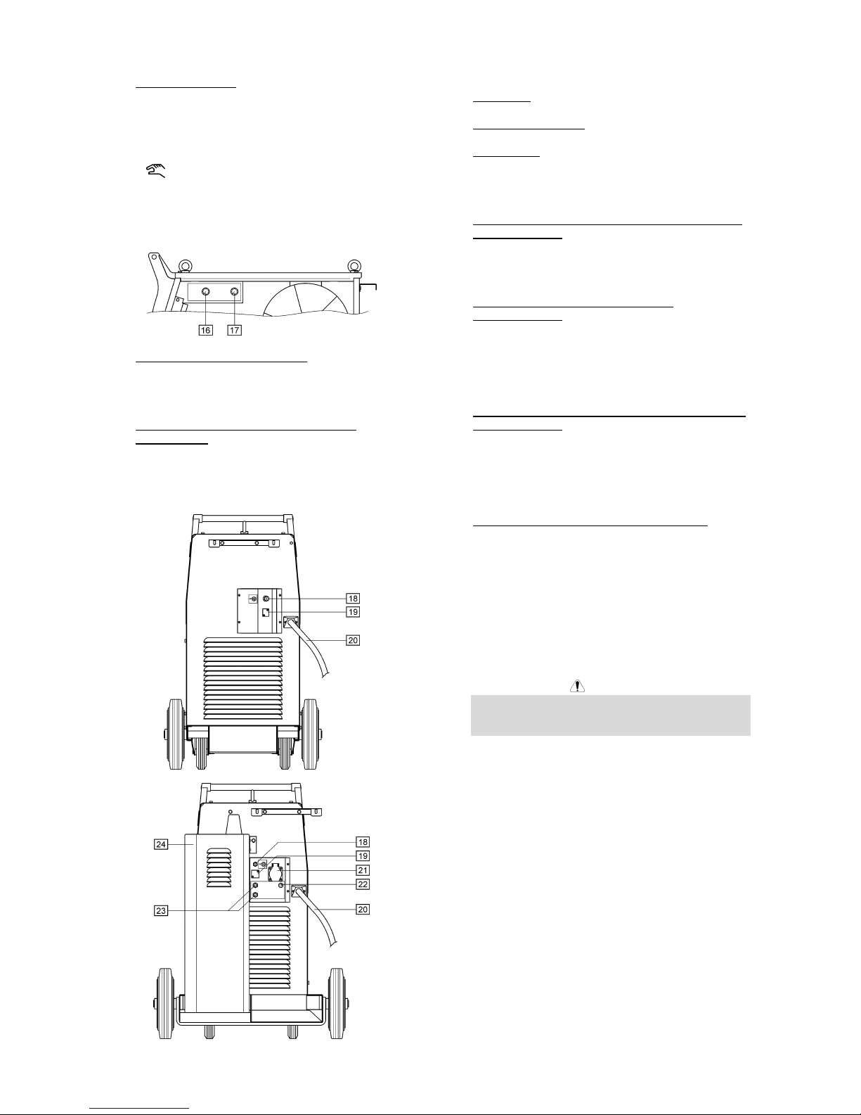
C-4
15. Zustandsanzeigen: Die Lampen zeigen den
aktuellen Modus der Maschine an:
SYNERGIC
Wenn diese Lampe leuchtet, dann
arbeitet die Maschine im Synergic
(synergetischen) Betrieb.
Wenn diese Lampe leuchtet, dann
arbeitet die Maschine im Handbetrieb.
Stellen Sie die gewünschte Arbeitsweise mit Hilfe
des Bedienknopfes für Schweißmaterial und
Gasgemisch ein [17].
16. Einstellknopf Drahtdurchmesser: Ermöglicht die
Einstellung des Drahtdurchmessers, für den
Schweißprozess. Dieses Merkmal ist nur im
synergetischen Betrieb verfügbar.
17. Einstellknopf Wahl Schweißwerkstoff und
Gasgemisch : Ermöglicht:
• Auswahl des Schweißwerkstoffes und des
dafür geeigneten Gasgemisches.
• Einstellung von Handbetrieb oder synergischer
Arbeitsweise.
18. Anschluss: Schutzgas.
19. Öffnung (abgedeckt): Für CO2 Gas-Vorwärmer.
20. Primärkabel: Verbinden Sie die Stromquelle mit
dem Eingangskabel, das für diese Maschine
geeignet ist. Dies darf nur von qualifiziertem
Fachpersonal durchgeführt werden.
21. Netzanschluß für die Kühler-Einheit (nur Modell mit
Wasserkühlung): Für den Betrieb der KühlerEinheit. Der Anschluss gibt 230V AC - 2.5A ab und
besitzt Überspannungsschutz [22]. Siehe Punkt
[24] für weitere Einzelheiten.
22. Überspannungsschutz (nur Modell mit
Wasserkühlung): Schützt den Anschluß der KühlerEinheit [21]. Die Stromversorgung wird abgeschaltet, wenn eine Stromstärke von 2.5A
überschritten wird. Der Schutzschalter muß
gedrückt werden, damit die Stromversorgung
gewährleistet ist.
23. Schnellverbindungskupplungen (nur Ausführung mit
Wasserkühlung): Zum Anschluß des
Wasserschlauches. Der Brenner sollte mit den
Schnellverbindungskupplungen an der Vorderseite
der Maschine verbunden werden. Der Kühler [24]
wird an die Schnellverbinder an der Rückseite der
Maschine angeschlossen.
24. Kühler (nur Ausführung mit Wasserkühlung): Wird
zur Kühlung des Schweißbrenners verwendet. Wird
durch die Maschine automatisch ein- und
ausgeschaltet:
• Wenn der Schweißvorgang beginnt, wird der
Kühler automatisch eingeschaltet.
• Wenn der Schweißvorgang unterbrochen wird,
arbeitet der Kühler noch ca. 5min weiter.
Danach schaltet er automatisch ab.
• Wird der Schweißvorgang innerhalb der 5min
wieder gestartet arbeitet der Kühler weiter.
WARNUNG
Lesen Sie die Bedienanleitung für den Kühler
sorgfältig durch, bevor sie diesen an die Maschine
anschließen.
Anschlüsse Schweißkabel
Stecken Sie den Stecker für das Erdungskabel in den
Anschluß [10] oder [11]. Das andere Ende dieses
Kabels verbindet Schweißklemme und Werkstück.
Sorgen Sie dafür, dass Drahtführungsschlauch und
Kontaktdüse zum Schweißdraht und dessen
Durchmesser passen.
Bestückung der Maschine mit der
Drahtelektrode
Öffnen Sie die Seitenabdeckung der Maschine.
Lösen Sie die Befestigungskappe von der Hülse.
Stecken Sie die Spule mit dem Draht so auf die Hülse,
dass sich die Spule beim Einführen des Drahtes in die
Drahtzuführung im Uhrzeigersinn dreht.
Gewährleisten Sie, dass die Paßfeder in die Bohrung
Page 25
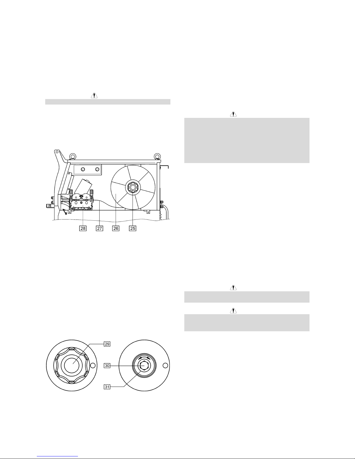
C-5
der Spule eingeführt wird.
Schrauben Sie die Befestigungskappe wieder auf.
Verwenden Sie beim Aufstecken der Drahtrolle die
richtige Nut, die mit dem Drahtdurchmesser
übereinstimmt.
Legen Sie das Drahtende frei und schneiden Sie das
gebogene Ende ab. Es darf kein Grat vorhanden sein.
WARNUNG
Scharfe Drahtenden können zu Verletzungen führen.
Drehen Sie die Spule in Uhrzeigerrichtung und führen
Sie den Draht in die Vorschubeinheit sowie den EuroAnschluß ein.
Stellen Sie die Spannung an der Druckrolle der
Drahtvorschubeinheit ein.
25. Adapter.
26. Drahtspule.
27. Schweißdraht.
28. Drahtvorschubmechanismus.
Die Maschine eignet sich für 15kg (300mm) Drahtspulen.
Bremseneinstellung der Spulen - Achse
Um unkontrolliertes Abrollen des Schweißdrahtes zu
vermeiden, ist die Spulen-Achse mit einer Bremse
ausgestattet.
Eingestellt wird die Bremse mit einer Schraube M10, an
der Innenseite der Achse. Diese Schraube ist sichtbar
nach Entfernung der Befestigungsschraube der SpulenAchse.
29. Befestigungsschraube.
30. Einstellschraube M10.
31. Druckfeder.
Der Federdruck nimmt zu, wenn die Schraube im
Uhrzeigersinn gedreht wird. Die Bremskraft nimmt dann
auch zu.
Wenn Sie die Schraube gegen den Uhrzeiger drehen,
nehmen der Federdruck und die Bremskraft ab.
Nach dem Einstellen kann man die Befestigungsschraube wieder anbringen.
Einstellung Druck Drahtvorschubrolle
Die Druckkraft wird durch Drehen der Einstellmutter
verändert; in Uhrzeigerrichtung wird diese erhöht, entgegen der Uhrzeigerrichtung wird die Kraft verringert.
WARNUNG
Ist die Drahtspannung zu niedrig, gleitet die
Vorschubrolle über den Draht. Ist die Drahtspannung zu
hoch, besteht die Gefahr, dass der Draht sich verformt.
Dies kann zu Vorschubproblemen im Brenner führen.
Es muss also unbedingt die richtige Spannung
eingestellt werden. Verringern Sie die Spannung, bis die
Rolle anfängt zu gleiten. Drehen Sie dann die
Schrauben einen Schlag im Uhrzeigersinn.
Einfädeln des Drahtes in den SchweißBrenner
Schließen Sie einen geeigneten Schweißbrenner an den
Euro-Anschluß an. Die Parameter für Brenner und
Schweißquelle müssen übereinstimmen.
Schalten Sie die Stromzufuhr ein (Hauptschalter [1]),
indem Sie den Schalter auf “I” stellen.
Entfernen Sie die Gasdüse und die Stromkontaktdüse
vom Schweißbrenner.
Stellen Sie den Drahtvorschub mit Hilfe des WFSKnopfes [7] auf etwa 10m/min ein.
Stellen Sie den Schalter Manueller
Drahtvorschub/Gastest [5] in die „Manueller VorschubStellung“ und halten diese solange, bis die Elekrode aus
der Kontaktdüse des Schweißbrenners herausschaut.
WARNUNG
Halten Sie das Brennerende in sicherer Entfernung von
Augen und Händen, während der Draht zugeführt wird.
WARNUNG
Wenn ausreichend Draht aus der Maschine austritt,
schalten Sie diese ab, bevor Sie die Gasdüse und die
Kontaktdüse wieder aufsetzen.
Gas-Versorgung
Verbinden Sie den Gasschlauch mit dem Gasanschluss
auf der Rückseite der Maschine.
Stellen Sie die Gasflasche auf den Flaschenträger und
sichern Sie die Flasche mit der Kette.
Entfernen Sie die Sicherungskappe von der Gasflasche
und schließen Sie den Druckminderer an.
Verbinden Sie den Gasschlauch der Maschine mit dem
Druckminderer.
Manuelles MIG / MAG-Schweißen
Damit Sie manuell MIG/MAG-schweißen können,
Page 26
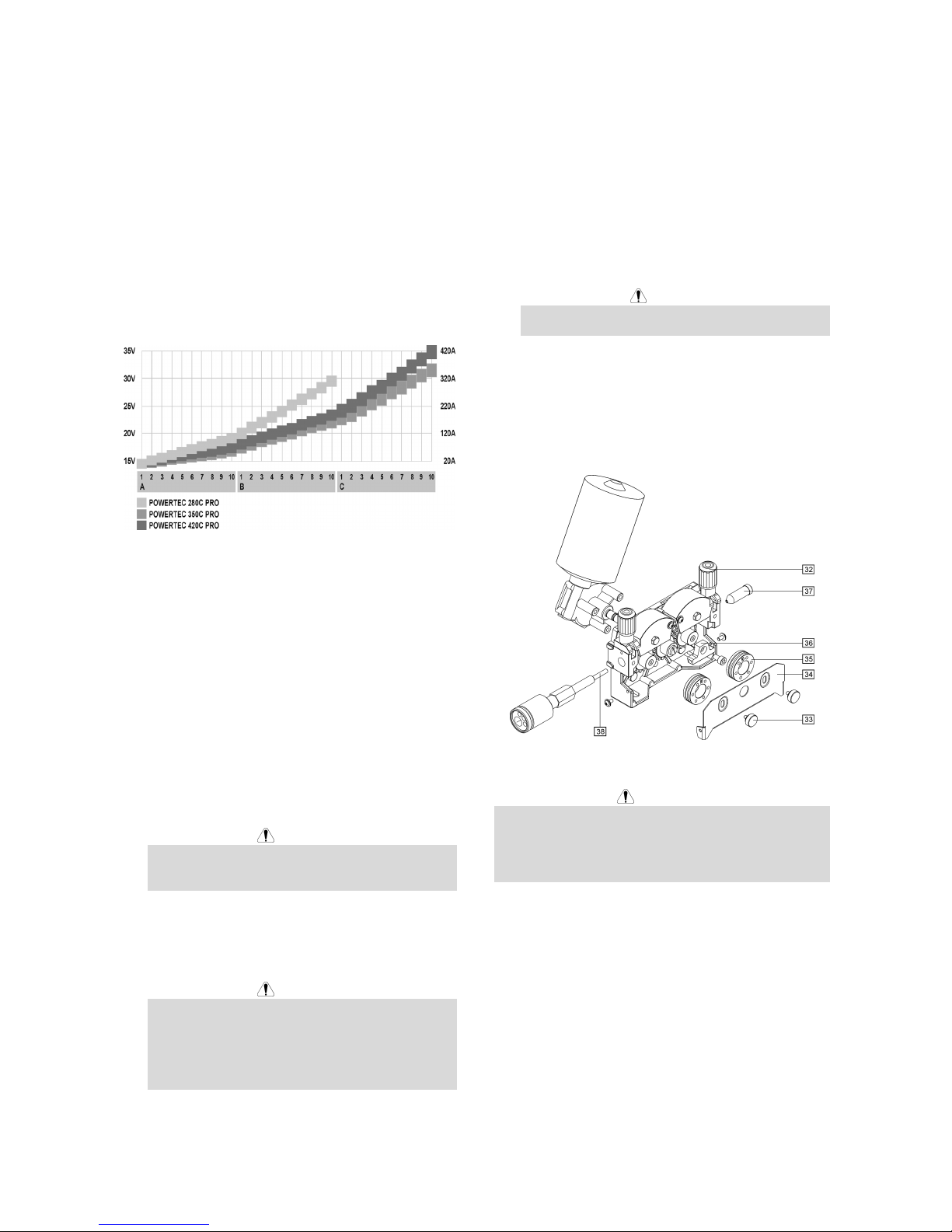
C-6
müssen Sie:
• Eingangsstromkabel anschließen.
• Schalten Sie die Maschine ein mit dem
“Hauptschalter”[1] (Lampe leuchtet auf).
• Drahteinfädeln mit “cold inch”-Schaltung [5].
• Kontrollieren Sie den Gasstrom mit der “Gas-
Purge”-Schaltung [5].
• Den Bedienknopf [17] auf Handbetrieb stellen
(überprüfen, dass in der Anzeige [15] Handbetrieb
leuchtet).
• Die richtige Schweißspannung entsprechend der
gewählten Betriebsart und der Werkstoffdicke mit
Schalter [3] und die Drahtvorschubgeschwindigkeit
mit dem WFS-Schalter [7] einstellen. Die
Darstellung unten soll bei der Einstellung der
Schweißparameter helfen:
• Die Maschine ist nun schweißbereit.
Synergisches MIG / MAG-Schweißen
Damit Sie synergisch MIG/MAG-schweißen können,
müssen Sie:
• Eingangsstromkabel anschließen.
• Schalten Sie die Maschine ein mit dem
“Hauptschalter”[1] (Lampe leuchtet auf).
• Drahteinfädeln mit “cold inch”-Schaltung [5].
• Kontrollieren Sie den Gasstrom mit der “Gas-
Purge”-Schaltung [5].
• Den Wahlschalter für den Drahtdurchmesser [16] in
die Stellung für den Durchmesser des verwendeten
Drahtes drehen.
• Den Einstellknopf [17] für Schweißwerkstoff und
Gasgemisch in die für den verwendeten Werkstoff
erforderliche Stellung bringen.
WARNUNG
Wenn das ausgewählte Schweißverfahren keinen
synergetischen Modus besitzt, erscheinen auf der
Anzeige “A” drei waagerechte Striche.
• Stellen Sie die korrekte Schweißspannung für das
ausgewählte Schweißverfahren und die Dicke des
zu schweißenden Werkstoffes mit dem “Schalter für
die Schweißspannung” [3] ein.
WARNUNG
Beim synergetischen Betrieb wählt die Maschine die
geeignete Drahtvorschubgeschwindigkeit für jede
gewählte Position des Schalters [3] selbständig aus.
Mit dem WFS-Knopf [7] kann der automatisch
festgelegte Wert jedoch um +/- 25% verändert
werden.
• Die Maschine ist nun schweißbereit.
Auswechseln der Antriebsrollen
Die Maschine besitzt werksseitig zwei
Drahtantriebsrollen (1.0 und 1.2 mm). Für andere
Drahtdurchmesser sind entsprechende Antriebsrollenkits
erhältlich (Siehe Kapitel Zubehörteile). So können Sie
die Rollen auswechseln:
• Schalten Sie die Maschine ab.
• Lösen Sie den Hebel für die Druckrolle [32].
• Lösen Sie die Befestigungskappe [33].
• Öffnen Sie die Schutzabdeckung [34].
• Ersetzen Sie die bisherigen Antriebsrollen [35]
durch die Neuen.
WARNUNG
Für Drähte mit Durchmessern >1,6 mm sind
folgende Teile auszuwechseln:
• Das Führungsrohr für die Vorschubkonsole [36]
und [37].
• Das Führungsrohr für den Euro-Anschluß [38].
• Ersetzen Sie die Schutzabdeckung [34] und
schrauben Sie diese an die Antriebsrollen an.
• Befestigen Sie die Schutzabdeckung mit den
Befestigungsschrauben [33].
Wartung
WARNUNG
Für Wartung und Reparatur des Gerätes konsultieren
Sie bitte Ihren Fachhändler oder die Lincoln Electric.
Eine unsachgemäß durchgeführte Wartung oder
Reparatur durch eine nicht qualifizierte Person führt zum
Erlöschen der Garantie.
Die Wartungsintervalle können abhängig von den
Arbeitsbedingungen der Maschine schwanken.
Ein schwerwiegender Schaden ist unverzüglich zu
melden.
Laufende Wartung (täglich)
• Überprüfen der Kabel und aller Anschlüsse.
Ersetzen Sie diese, wenn erforderlich.
• Entfernen Sie Schweißspritzer von der Schweiß-
düse. Schweißspritzer können den Fluß des
Schutzgases von der Schweißdüse zum Lichtbogen
beeinflussen.
• Überprüfen Sie den Zustand der Düse und ersetzen
Sie diese, wenn erforderlich.
• Überprüfen Sie Zustand und Betrieb des Lüfters –
Page 27

C-7
halten Sie dessen Lüftungsschlitze frei und sauber.
Periodische Wartung (alle 20 Betriebsstunden,
mindestens einmal im Jahr)
Zusätzlich zur laufenden Wartung sind folg. Arbeiten
durchzuführen:
• Halten Sie die Maschine sauber. Verwenden Sie
einen trockenen Luftstrom mit geringem Luftdruck.
Entfernen Sie den Staub von der äußeren Abdeckung und aus dem Innern des Gehäuses.
• Überprüfen Sie alle Schrauben auf festen Sitz und
ziehen Sie diese nach, wenn erforderlich.
WARNUNG
Die Maschine muß während der Durchführung der
Wartungsarbeiten vom Netz getrennt sein. Nach jeder
Reparatur sind geeignete Tests durchzuführen, um die
Betriebssicherheit zu überprüfen.
Elektromagnetische Verträglichkeit (EMC)
11/04
Diese Maschine wurde unter Beachtung aller zugehörigen Normen und Vorschriften gebaut. Dennoch kann es unter
besonderen Umständen zu elektromagnetischen Störungen anderer elektronischer Syteme (z.B. Telefon, Radio, TV,
Computer usw.) kommen. Diese Störungen können im Extremfall zu Sicherheitsproblemen der beeinflussten Systeme
führen. Lesen Sie deshalb diesen Abschnitt aufmerksam durch, um das Auftreten elektromagnetischer Störungen zu
reduzieren oder ganz zu vermeiden.
Diese Maschine ist für den industriellen Einsatz konzipiert worden. Bei Benutzung dieser Anlage in
Wohngebieten sind daher besondere Vorkehrungen zu treffen, um Störungen durch elektromagnetische
Beeinflussungen zu vermeiden. Halten Sie sich stets genau an die in dieser Bedienungsanleitung
genannten Einsatzvorschriften. Falls dennoch elektromagnetische Störungen auftreten, müssen geeignete
Gegenmaßnahmen getroffen werden. Kontaktieren Sie gegebenenfalls den Kundendienst der Lincoln Electric.
Technische Änderungen der Anlage sind nur nach schriftlicher Genehmigung des Herstellers zulässig.
Vergewissern Sie sich vor der Inbetriebnahme des Schweißgerätes, dass sich keine für elektromagnetische Störungen
empfänglichen Geräte und Anlagen im möglichen Einflussbereich befinden. Dies gilt besonders für:
• Steuerleitungen, Datenkabel und Telefonleitungen.
• Radio und Televisions-Sender oder -Empfänger sowie deren Kabelverbindungen. Computer oder
computergesteuerte Anlagen.
• Elektronische Sicherheitseinrichtungen und Steuereinheiten für industrielle Anlagen. Elektronische Mess- und
Kalibriereinrichtungen.
• Medizinische Apparate und Geräte, Hörgeräte oder persönliche Implantate wie Herzschrittmacher usw. Achtung!
Informieren Sie sich vor Inbetriebnahme der Anlage in der Nähe von Kliniken und Krankenhäusern über die hierzu
gültigen Vorschriften, und sorgen Sie für die exakte Einhaltung aller erforderlichen Sicherheitsmaßnahmen!
• Prüfen Sie grundsätzlich die elektromagnetische Verträglichkeit von Geräten, die sich im Einflussbereich der
Schweißanlage befinden.
• Dieser Einflussbereich kann in Abhängigkeit der physikalischen Umstände in seiner räumlichen Ausdehnung stark
variieren.
Befolgen Sie zusätzlich die folgenden Richtlinien um elektromagnetische Abstrahlungen zu reduzieren:
• Schließen Sie die Maschine stets nur wie beschrieben an. Falls dennoch Störungen auftreten, muss eventuell ein
zusätzlicher Netzfilter eingebaut werden.
• Halten Sie die Länge der Schweißkabel möglichst auf ein erforderliches Mindestmaß begrenzt. Wenn möglich,
sollte das Werkstück separat geerdet werden. Beachten Sie stets bei allen Maßnahmen, dass hierdurch keinerlei
Gefährdung von direkt oder indirekt beteiligten Menschen verursacht wird.
• Abgeschirmte Kabel im Arbeitsbereich können die elektromagnetische Abstrahlung reduzieren. Dies kann je nach
Anwendung notwendig sein.
Page 28

C-8
Technische Daten
POWERTEC 280C, 350C & 420C PRO:
NETZEINGANG
Leistungsaufnahme
280C PRO:
12 kVA @ 40% ED
350C PRO:
16 kVA @ 40% ED
Netzeingangsspannung
230 / 400V ± 10%
Dreiphasig
420C PRO:
21 kVA @ 40% ED
Frequenz
50 Hertz (Hz)
LEISTUNGSDATEN BEI 40°C UMGEBUNGSTEMPERATUR
Einschaltdauer
(basierend auf 10min-Zyklus)
Ausgangsstromstärke Ausgangsspannung
280C PRO:
40%
60%
100%
280A
230A
175A
28.0 Vdc
25.5 Vdc
22.8 Vdc
350C PRO:
40%
60%
100%
350A
285A
220A
31.5 Vdc
28.2 Vdc
25.0 Vdc
420C PRO:
40%
60%
100%
420A
345A
265A
35.0 Vdc
31.3 Vdc
27.3 Vdc
AUSGANGLEISTUNG
Schweißstrombereich Maximale Leerlaufspannung
280C PRO:
30A - 280A
280C PRO:
39 Vdc
350C PRO:
30A - 350A
350C PRO:
42 Vdc
420C PRO:
30A - 420A
420C PRO:
49 Vdc
PRIMÄRKABELQUERSCHNITTE UND ABSICHERUNG
Sicherung oder Sicherungsautomat Primärkabel
280C PRO:
32A träge (230V Eingangsspannung)
20A träge (400V Eingangsspannung)
280C PRO:
4 Adern, 4mm
2
350C PRO:
40A träge (230V Eingangsspannung)
25A träge (400V Eingangsspannung)
350C PRO:
4 Adern, 4mm
2
420C PRO:
63A träge (230V Eingangsspannung)
32A träge (400V Eingangsspannung)
420C PRO:
4 Adern, 6mm
2
ABMESSUNGEN UND GEWICHT
Gewicht
280C PRO:
142 kg
350C PRO:
147 kg
420C PRO:
157 kg
Höhe
910 mm
Breite
565 mm
700 mm
(wassergekühlte-Version)
Länge
1030 mm
420C PRO:
(wassergekühlt)
183 kg
Zulässige Umgebungstemperaturen
-10°C bis +40°C
Zulässige Lagerungstemperaturen
-25°C bis +55°C
Page 29

D-1
Seguridad
11/04
ATENCION
Este equipo debe ser utilizado por personal cualificado. Asegúrese de que todos los procedimientos de instalación,
funcionamiento, mantenimiento y reparación son realizados únicamente por personal cualificado. Lea y comprenda este
manual antes de trabajar con el equipo. No seguir las instrucciones que se indican en este manual podría provocar
lesiones personales de distinta gravedad, incluída la muerte o daños a este equipo. Lea y comprenda las explicaciones
de los símbolos de advertencia, que se muestran a continuación. Lincoln Electric no se hace responsable de los daños
producidos por una instalación incorrecta, una falta de cuidado o un funcionamiento inadecuado.
¡PELIGRO!: Este símbolo indica qué medidas de seguridad se deben tomar para evitar lesiones
personales de diferente gravedad, incluída la muerte, o daños a este equipo. Protéjase usted y a los
demás contra posibles lesiones personales de distinta gravedad, incluída la muerte.
LEA Y COMPRENDA LAS INSTRUCCIONES: Asimile el contenido de este manual de instrucciones
antes de trabajar con el equipo. La soldadura al arco puede ser peligrosa. NO seguir las
instrucciones que se indican en este manual podría provocar lesiones personales de distinta
gravedad, incluída la muerte, o daños a este equipo.
LA DESCARGA ELECTRICA PUEDE MATAR: Los equipos de soldadura generan voltajes elevados.
No toque el electrodo, la pinza de masa, o las piezas a soldar cuando el equipo esté en marcha.
Aíslese del electrodo, la pinza de masa, o las piezas en contacto cuando el equipo esté en marcha.
EQUIPOS ELÉCTRICOS: Desconecte la alimentación del equipo desde el interruptor de red o desde
la caja de fusibles antes de reparar o manipular el interior de este equipo. Conecte el tierra de este
equipo de acuerdo con el reglamento eléctrico local.
EQUIPOS ELÉCTRICOS: Inspeccione con regularidad los cables de red, electrodo y masa. Si hay
algún daño en el aislamiento sustituya dicho cable inmediatamente. No coloque directamente la
pinza portaelectrodos sobre la mesa de soldadura o sobre cualquier otra superficie que esté en
contacto con la pinza de masa para evitar el riesgo de un cebado accidental del arco.
LOS CAMPOS ELÉCTRICOS Y MAGNÉTICOS PUEDEN SER PELIGROSOS: La corriente eléctrica
que circula a través de un conductor origina campos eléctricos y magnéticos (EMF) localizados. Los
campos EMF pueden interferir con los marcapasos, las personas que utilicen estos dispositivos
deben consultar a su médico antes de acercarse a una máquina de soldar.
CUMPLIMIENTO CE: Este equipo cumple las directivas de la CEE.
LOS HUMOS Y LOS GASES PUEDEN SER PELIGROSOS: La soldadura puede producir humos y
gases peligrosos para la salud. Evite respirarlos. Utilice la suficiente ventilación y/o extracción de
humos para mantener los humos y gases alejados de la zona de respiración.
LA LUZ DEL ARCO PUEDE QUEMAR: Utilice una pantalla de protección con el filtro adecuado para
proteger sus ojos de la luz y de las chispas del arco cuando se suelde o se observe una soldadura
por arco abierto. Use ropa adecuada de material ignífugo para proteger la piel de las radiaciones del
arco. Proteja a otras personas que se encuentren cerca del arco y/o adviértales que no miren
directamente al arco ni se expongan a su luz o sus proyecciones.
LAS PROYECCIONES DE SOLDADURA PUEDEN PROVOCAR UN INCENDIO O UNA
EXPLOSIÓN: Retire del lugar de soldadura todos los objetos que presenten riesgo de incendio.
Tenga un extintor de incendios siempre a mano. Recuerde que las chispas y las proyecciones
calientes de la soldadura pueden pasar fácilmente por aberturas pequeñas. No caliente, corte o
suelde tanques, tambores o contenedores hasta haber tomado las medidas necesarias para asegurar
que tales procedimientos no van a producir vapores inflamables o tóxicos. No utilice nunca este
equipo cuando haya presente gases inflamables, vapores o líquidos combustibles.
LA SOLDADURA PUEDE QUEMAR: La soldadura genera una gran cantidad de calor. Las
superficies calientes y los materiales en el área de trabajo pueden provocar quemaduras graves.
Utilice guantes y pinzas para tocar o mover los materiales que haya en el área de trabajo.
MARCAJE SEGURIDAD: Este equipo es adecuado como fuente de potencia para operaciones de
soldadura efectuadas en un ambiente con alto riesgo de descarga eléctrica.
Page 30

D-2
LA BOTELLA DE GAS PUEDE EXPLOTAR SI ESTA DAÑADA: Emplee únicamente botellas que
contengan el gas de protección adecuado para el proceso utilizado y reguladores en buenas
condiciones de funcionamiento, diseñados para el tipo de gas y la presión utilizadas. Mantenga
siempre las botellas en posición vertical y encadenadas a un soporte fijo. No mueva o transporte
botellas de gas que no lleven colocado el capuchón de protección. No deje que el electrodo, la pinza
portaelectrodo, la pinza de masa o cualquier otra pieza con tensión eléctrica toque la botella de gas.
Las botellas de gas deben estar colocadas lejos de las áreas donde puedan ser golpeadas o ser
objeto de daño físico, o a una distancia de seguridad de las operaciones de soldadura.
Instalación e Instrucciones de Funcionamiento
Lea esta sección antes de la instalación y puesta en
marcha del equipo.
Emplazamiento y entorno
Esta máquina puede trabajar en ambientes agresivos.
Sin embargo, es importante tener una serie de
precauciones de manera que aseguren un
funcionamiento duradero y fiable.
• No coloque ni haga funcionar la máquina sobre una
superficie que tenga un ángulo de inclinación mayor
de 15º desde la horizontal.
• No utilice esta máquina para precalentar tubos.
• Este equipo debe situarse en un lugar donde haya
una buena circulación de aire limpio, sin
restricciones de aire. Cuando esté funcionando no
cubrirlo con papel, ropa o trapos.
• Se debe restringir al mínimo la entrada de polvo y
suciedad en el interior de la máquina.
• Este equipo tiene un grado de protección IP23.
Mantenerlo seco y no situarlo en suelos húmedos o
en charcos.
• Coloque el equipo alejado de maquinaria que
trabaje por radio control. El normal funcionamiento
del equipo podría afectar negativamente a dichos
equipos, provocando serias averías y daños en los
mismos. Ver la sección compatibilidad
electromagnética en este manual.
• No trabaje en zonas donde la temperatura ambiente
supere los 40º C.
Factor marcha y Sobrecalentamiento
El factor marcha de la máquina es el porcentaje de
tiempo en ciclos de 10 minutos, durante el cual el
operario puede hacer funcionar la máquina al valor
nominal de la corriente de soldadura.
Ejemplo: 60% Factor marcha:
Soldando durante 6 min. Parar durante 4 min.
Sobrepasar el tiempo de soldadura del factor marcha
puede provocar que se active el circuito de protección
térmica.
El transformador de soldadura en la máquina está
protegido del sobrecalentamiento a través de un
termostato. Cuando la máquina está sobrecalentada, la
corriente de salida se desconectará “OFF” y la luz del
indicador térmico se encenderá “ON”. Cuando la
máquina se haya enfriado, la luz del indicador térmico
se apagará y la máquina volverá a su funcionamiento
normal. Nota: Por razones de seguridad, la máquina no
volverá a conectar su salida si no se libera previamente
el gatillo de la pistola.
Minutos o descenso
Factor marcha
Conexión a la red
Instalación y tomas de salida de red deberían
protegerse de acuerdo a las normas.
Comprobar la tensión de red, fases y frecuencia
suministrada a la máquina antes de conectarla. Verificar
la conexión del cable de tierra de la máquina a la toma
de la red. La entrada de voltaje permitidos son 3x230V
y 3x400V 50Hz (400V: preparada de fábrica). Para más
información sobre el suministro de la entrada de
corriente ver la sección de especificaciones técnicas de
este manual o la placa de características de esta
máquina.
Si necesita efectuar el cambio de tensión en la máquina:
• Asegúrese de que el cable de entrada de corriente
está desconectado de la entrada principal y la
máquina está parada (OFF).
• Quite el panel lateral izquierdo de la máquina.
• Reconecte X11 y X12 según indica el diagrama.
X12
400V
X11
X12
230V
X11
• Recoloque el panel lateral izquierdo.
Asegúrese de que la potencia de entrada es la
adecuada para el correcto funcionamiento de la
máquina. Es necesario fusibles retardados (o interruptor
margnetotérmico curvo tipo “D”) y sección de cable
indicados en las especificaciones técnicas de este
manual.
Referente a los puntos [1] y [20] del dibujo inferior.
Conexiones de Salida
Referente a los puntos [8], [10] y [11] del dibujo inferior.
Page 31

D-3
Controles y Características de
funcionamiento
1. Interruptor de Red y Luz indicador de Potencia:
Después que el cable de red es conectado y al
accionar el interruptor de red a la posición on, se
encenderá la luz para indicar que la máquina está
conectada y preparada para soldar.
2. Indicador Sobrecarga Térmica: Este indicador se
iluminará cuando la máquina esté sobrecargada y la
salida haya sido desconectada. Dejar la máquina
hasta que los componentes internos se enfríen,
cuando la luz indicadora se apague, la máquina
volverá a funcionar con normalidad.
3. Conmutadores de Cambio de la Tensión de
Soldadura: POWERTEC 280C tiene 2
conmutadores (2 y 10 pasos). Las POWERTEC
350C y 420C tienen 2 conmutadores (3 y 10 pasos).
4. Modo Pulsador Pistola: Este modo permite la
selección de 2-tiempos ó 4-tiempos. A continuación
se muestra la funcionalidad del modo 2T/4T:
↑
Pulsador apretado
↓
Pulsador liberado
A. Corriente de soldadura.
B. Tiempo distancia hilo (Burnback).
C. Velocidad de hilo.
G. Gas.
5. Conmutador Hilo Manual / Gas Purga: Este
conmutador permite la alimentación en frío o flujo
de gas sin conectar la salida del voltaje.
6. Mando Marcha Lenta Alimentación Hilo: Facilita el
control de la velocidad de alimentación del hilo
antes del inicio de la soldadura, en el rango de 0,5
a1,0 del valor fijado por el "Mando Velocidad
Alimentación Hilo" [7].
7. Mando WFS (Velocidad Alimentación Hilo): Facilita
el control continuo de la velocidad de alimentación
del hilo en el rango de 1,0 a 20m/min con modo
manual o corrección de la velocidad
automáticamente adaptada por la máquina en el
rango ±25% en el modo sinérgico.
8. Euroconector: Para conectar la pistola de
soldadura.
9. Mando distancia hilo, tiempo Burnback: Permite
obtener la longitud deseada de hilo, el cuál
sobresale al final de la boquilla de la pistola al final
de la soldadura; el rango se ajusta de 8 a 250ms.
10. Zócalo de Salida con Alta Inductancia: Para la
conexión del cable de masa.
11. Zócalo de Salida con Baja Inductancia: Para la
conexión del cable de masa.
12. Regleta Conexiones Cambio Polaridad: Facilita la
selección de polaridad de la tensión de soldadura
(+/-), que se dará en la pistola de soldadura (de
fábrica, por defecto, polaridad: “+” en la pistola de
soldadura).
Si es necesario cambiar la polaridad de soldadura,
se debe:
• Apagar la máquina y desconectarla del
suministro de la red principal.
• Sacar la cubierta de la regleta de conexiones.
• Colocar los conectores según el dibujo inferior.
• Colocar la cubierta de la regleta de conexiones.
13. Display A: Muestra el valor real de la corriente de
soldadura (en A), y una vez finalizado el proceso de
soldadura, muestra el valor medio de la corriente de
soldadura durante unos 5s. Después de este
tiempo, el visor muestra el valor ajustado de la WFS
(en m/min) – en modo manual o corrección de la
velocidad automáticamente adaptada por la
máquina, en el rango 0,75-1,25 en modo sinérgico.
14. Display V: Muestra el valor real de la tensión de
soldadura (en V), y una vez finalizado el proceso de
soldadura, muestra el valor medio de la tensión de
soldadura durante 5s. Después de este tiempo, el
display queda en blanco.
Page 32

D-4
15. Indicadores de trabajo: Estas lámparas muestran el
modo de trabajo de la máquina:
SYNERGIC
Si está encendida, la máquina trabaja
en modo Sinérgico (modo automático).
Si está encendida, la máquina trabaja
en modo Manual.
Seleccione el trabajo deseado con el "Control
Selección Material a Soldar y Gas Mezcla" [17].
16. Control Diámetro Hilo: Permite la elección del
diámetro de hilo requerido para el proceso de
soldadura deseado. Esta característica está
disponible solo para el modo sinérgico.
17. Control Selección Material a Soldar y Gas Mezcla:
Este control facilita la elección de:
• Los materiales a soldar y el gas mezcla
adecuado.
• El modo de trabajo manual / sinérgico.
18. Rácor gas: Para conexión manguera de gas.
19. Orificio cubierto: Zócalo para calentador de gas.
20. Cable Entrada Red: Conectar el cable de entrada
de red al valor nominal de corriente de salida y de
acuerdo a las normas apropiadas. Sólo puede
conectarse a través de personal cualificado.
21. Toma Suministro de Corriente Refrigerador (Sólo
para modelo refrigerado por agua): Para el
suministro de la unidad de refrigeración. El zócalo
tiene una salida intermitente de 230V, 2.5A y está
protegido por el interruptor térmico [22]. Ver punto
[24] para más detalles.
22. Interruptor Térmico (Sólo para modelo refrigerado
por agua): Protege la toma de suministro de
corriente al Refrigerador [21]. Desconecta el
suministro de energía cuando la corriente supera
2.5A. Presionar para restablecer el suministro de
corriente.
23. Acoplamientos de Conexión Rápida (Sólo para
modelo refrigerado por agua): Para la conexión de
la manguera de agua. La pistola de soldadura debe
conectarse a los acoplamientos de conexión rápida
colocados en el panel frontal de la máquina. El
refrigerador [24] debe conectarse a los
acoplamientos de conexión rápida colocados en el
panel trasero de la máquina.
24. Refrigerador (Solo para modelo refrigerado por
agua): Refrigera la pistola de soldadura refrigerada
por agua. Se conecta y desconecta
automáticamente por la máquina como sigue:
• Cuando se inicia una soldadura, el Refrigerador
se conecta automáticamente.
• Cuando la soldadura se para, el Refrigerador
continua funcionando durante unos 5min.,
después de este tiempo se desconecta
automáticamente.
• Si la soldadura se reinicia en un tiempo inferior
a los 5min., el Refrigerador continua
funcionando.
PRECAUCIÓN
Lea y comprenda el manual del refrigerador antes
de conectarlo a la máquina.
Conexiones Cables de Soldadura
Inserte el conector del cable de masa en el zócalo [10] o
[11]. El otro extremos de este cable se conecta a la
pieza a soldar con la pinza de masa.
Conecte en el Euroconector la pistola de soldar con la
boquilla de contacto y la espiral para el diámetro de hilo
y el material a soldar.
Cargando la Bobina de Hilo
Abra la cubierta lateral de la máquina.
Desenrosque el tornillo de fijación del eje soporte.
Cargue la bobina del hilo en el eje soporte de modo que
la bobina gire en el sentido horario cuando el hilo es
alimentado en el devanador.
Page 33
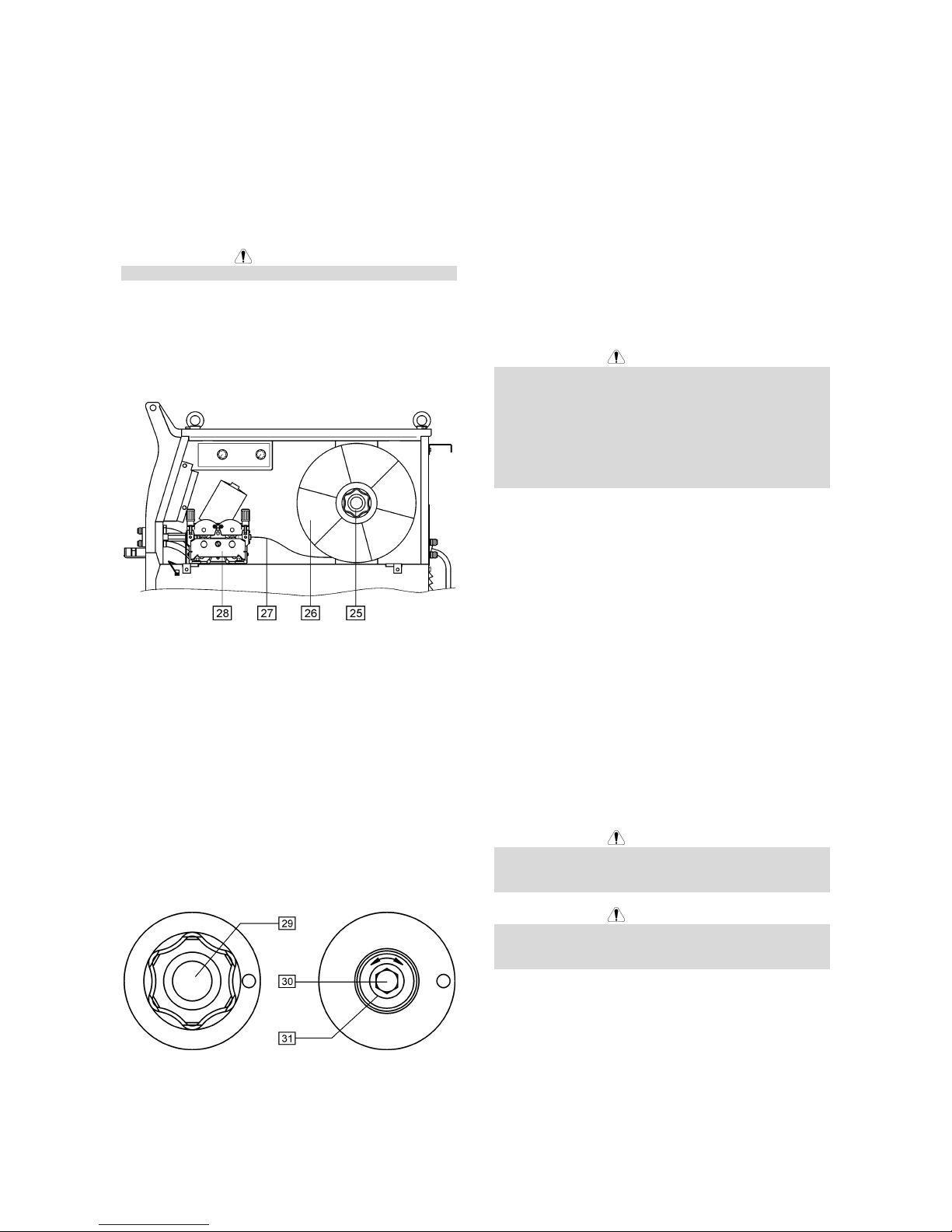
D-5
Asegúrese de que el pivote posicionador para la bobina
va en el agujero adecuado de la bobina.
Enrosque el tornillo de fijación del eje soporte.
Ponga el hilo sobre el rodillo utilizando la ranura correcta
correspondiente al diámetro del alambre.
Libere el extremo del hilo y corte el extremo doblado
asegurándose de que no tiene rebabas.
PRECAUCIÓN
El extremo afilado del hilo puede lastimar.
Gire la bobina del hilo en sentido horario e inserte el
extremo del hilo en el devanador hasta el límite del
Euroconector.
Ajuste correctamente la fuerza del rodillo de presión del
devanador.
25. Eje soporte carrete.
26. Bobina.
27. Hilo.
28. Unidad de arrastre.
La máquina está diseñada para utilizar bobinas de 15kg
(300mm).
Ajuste del freno del eje soporte carrete
Para evitar que la bobina pueda desenrrollarse
espontáneamente el soporte carrete es fijado con un
freno.
El ajuste se efectúa girando el tornillo M10, que se
encuentra situado en el interior del eje del soporte
carrete, después desenroscar el tornillo de fijación del
eje soporte carrete.
29. Tornillo de fijación.
30. Tornillo de ajuste M10.
31. Muelle presión.
Girando el tornillo M10 en la dirección de las agujas del
reloj, aumenta la tensión de la presión y Vd. puede
aumentar la presión del freno.
Girando el tornillo M10 en sentido contrario a las agujas
del reloj, reduce la tensión de la presión y Vd. puede
disminuir la presión del freno.
Una vez finalizado el ajuste, deberá enroscar el tornillo
de fijación del soporte carrete otra vez.
Ajustando la fuerza de los rodillos de
presión
La fuerza de la presión se ajusta girando la tuerca del
brazo en el sentido de las agujas del reloj para
incrementar la fuerza, y en sentido contrario a las agujas
del reloj para disminuir la fuerza.
PRECAUCIÓN
Si la presión es demasiado baja, el rodillo patinará en el
hilo. Si la presión es demasiado alta, el hilo podría
deformarse y causaría problemas de alimentación en la
pistola. La fuerza de la presión deberá ser la adecuada.
Disminuir la fuerza de la presión hasta que el hilo
empiece a deslizarse en el rodillo de arrastre y entonces
incrementar la fuerza ligeramente girando la tuerca de
ajuste con un cuarto de giro.
Insertar el hilo dentro de la pistola de
soldadura
Conecte la pistola de soldadura adecuada al
Euroconector, se equipararán los parámetros nominales
de la pistola y de la fuente de soldadura.
Conecte el suministro de energía (el interruptor principal
[1] en posición “I”).
Saque el difusor de gas y la boquilla de contacto de la
pistola de soldadura.
Ajuste la velocidad del devanador en la posición de
10m/min aproximadamente por medio del control WFS
[7].
Colocar el conmutador Avance Hilo Frío (Cold Inch) /
Purga Gas [5] en la posición “Cold Inch” y manténgalo
en esta posición hasta que el hilo salga por la boquilla
de contacto de la pistola de soldadura.
PRECAUCIÓN
Tenga la precaución de mantener los ojos y las manos
alejados del final de la pistola mientras está pasando el
hilo.
PRECAUCIÓN
Una vez el hilo ha terminado de pasar a través de la
pistola, ponga la máquina en posición“OFF“ antes de
colocar la boquilla de contacto y el difusor de gas.
Conexión Gas
Conecte la manguera de gas al rácor de entrada del
mismo, situado en el panel trasero de la máquina.
Ponga la botella de gas en la máquina y asegúrela con
una cadena.
Saque el capuchón de seguridad de la botella de gas e
instale el manorreductor en la misma.
Page 34

D-6
Conecte el tubo de gas de la máquina al regulador y
fíjelo con una brida.
Método de Soldadura MIG / MAG en
modo Manual
Para empezar el proceso de soldadura MIG/MAG con el
método manual, Vd. debe:
• Introducir el enchufe del cable de red en la toma de
corriente.
• Conecte la máquina ”ON” con el “interruptor de red”
[1] (debería encenderse una luz).
• Introduzca el hilo en la pistola utilizando el
conmutador Avance en frío ”Cold Inch“ [5].
• Comprobar el regulador con el conmutador en
posición ”Gas Purge” [5].
• Coloque el control [17] en posición Manual
(verifique que el indicador [15] tiene iluminado el
modo Manual).
• De acuerdo con el modo de soldadura seleccionado
y el espesor de material ajustar la tensión de
soldadura correcta con el conmutador [3] y la
velocidad de alimentación con el control WFS [7].
El diagrama inferior puede ser útil para la selección
de los ajustes de soldadura:
• Siguiendo las normas indicadas, Vd. puede
empezar a soldar.
Método de Soldadura MIG / MAG en
modo Sinérgico (automático)
Para empeza el proceso de soldadura MIG/MAG en
modo sinérgico, Vd. debe:
• Introducir el enchufe del cable de red en la toma de
corriente.
• Conecte la máquina ”ON” con el “interruptor de red”
[1] (debería encenderse una luz).
• Introduzca el hilo en la pistola utilizando el
conmutador Avance en frío ”Cold Inch“ [5].
• Comprobar el regulador con el conmutador en
posición ”Gas Purge” [5].
• Coloque el control de selección del diámetro de
alambre [16] en la posición correspondiente al
diámetro del hilo usado.
• Coloque el control de selección del material a soldar
y de mezcla de gas [17] en la posición
correspondiente al material usado.
PRECAUCIÓN
Si el proceso de soldadura seleccionado no tiene
modo sinérgico, en el display “A” aparecerán tres
rayas horizontales.
• En función del modo de soldadura seleccionado y
del espesor de material, ajuste la tensión de
soldadura correcta a través de los “Conmutadores
de Cambio de la Tensión de Soldadura” [3].
PRECAUCIÓN
En el modo de soldadura sinérgico, la máquina
selecciona automáticamente la velocidad de
alimentación hilo correcta para cada posición de los
“Conmutadores de Cambio de la Tensión de
Soldadura” [3]. El valor automático de velocidad
puede corregirse en el rango de ±25% por el control
WFS [7].
• Siguiendo las normas indicadas, Vd. puede
empezar a soldar.
Cambio de los Rodillos de Arrastre
La máquina está equipada (de fábrica) con rodillos de
arrastre para hilo de 1,0 y 1,2mm. Para otros diámetros
de hilo se dispone del kit adecuado de rodillos de
arrastre (ver capítulo Accessorios para pedir el kit
deseado). Para el cambio de los rodillos de arrastre
proceder como sigue:
• Desconectar la máquina.
• Liberar la palanca de presión del rodillo [32].
• Desenroscar el tornillo de sujeción [33].
• Abrir la tapa de protección [34].
• Cambiar los rodillos de arrastre [35] con los
compatibles correspondientes al diámetro de hilo
usado.
PRECAUCIÓN
Para hilos mayores de 1,6 mm de diámetro, se
tienen que cambiar las siguientes partes:
• El tubo guía intermedio de la cónsola del
alimentador [36] y guía de entrada [37].
• El tubo guía del Euroconector[38].
• Recolocar y apretar la tapa de protección [34] a los
rodillos de arrastre.
• Enroscar la tapa de protección por los tornillos de
sujeción [33].
Page 35

D-7
Mantenimiento
PRECAUCIÓN
Para cualquier tipo de trabajo de reparación o
mantenimiento, se recomienda contacte con el servicio
de asistencia técnica autorizado más cercano o con
Lincoln Electric. Los trabajos de reparación o
mantenimiento realizados por el personal o por servicios
técnicos no autorizados anularán la garantía del
fabricante.
La frecuencia de las operaciones de mantenimiento
puede variar en función del ambiente de trabajo en el
que se coloque la máquina.
Cualquier daño que se observe debe ser comunicado
inmediatamente.
Mantenimiento de rutina (cada día)
• Verificar la integridad de cables y conexiones.
Cambiarlos si es necesario.
• Quitar las salpicaduras de la boquilla de la pistola
de soldadura. Las salpicaduras pueden interferir el
flujo del gas de protección hacia el arco.
• Verificar el estado de la pistola de soldadura;
cambiarla, si es necesario.
• Verificar estado y funcionamiento del ventilador de
refrigeración. Mantenga limpias las rendijas de flujo
de aire.
Mantenimiento periódico (cada 200 horas de
trabajo o una vez al año como mínimo)
Efectuar el mantenimiento de rutina y además:
• Mantenga limpia la máquina. Empleando flujo de
aire seco (y de baja presión), quite el polvo de la
carcasa externa y del interior.
• Compruebe y apriete todos los tornillos.
PRECAUCIÓN
Desconectar la máquina del suministro de red antes de
cada mantenimiento y servicio. Después de cada
reparación, efectuar los ensayos adecuados para
comprobar la seguridad.
Compatibilidad Electromagnética (EMC)
11/04
Esta máquina ha sido diseñada de conformidad con todas las directivas y normas relativas a la compatibilidad
electromagnética. Sin embargo, todavía podría generar interferencias electromagnéticas que pueden afectar a otros
sistemas como son telecomunicaciones (teléfono, radio y televisión) u otros sistemas de seguridad. Estas interferencias
pueden ocasionar problemas de seguridad en los sistemas afectados. Lea y comprenda esta sección para eliminar o al
menos reducir los efectos de las interferencias electromagnéticas generadas por esta máquina.
Esta máquina ha sido diseñada para trabajar en zonas industriales. Para operar en una zona no industrial
es necesario tomar una serie de precauciones para eliminar las posibles interferencias electromagnéticas.
El operario debe instalar y trabajar con este equipo tal como se indica en este manual de instrucciones. Si
se detectara alguna interferencia electromagnética el operario deberá poner en práctica acciones
correctoras para eliminar estas interferencias con la asistencia de Lincoln Electric.
Antes de instalar el equipo de soldadura, el usuario deberá hacer una evaluación de los problemas de interferencias
electromagnéticas que se puedan presentar en el área circundante. Se deberá tener en cuenta lo siguiente:
• Cables de entrada y salida, cables de control, y cables de teléfono que estén en, o sean adyacentes al área de
trabajo y a la máquina.
• Emisores y receptores de radio y/o televisión. Ordenadores o equipos controlados por ordenador.
• Equipos de control y seguridad para procesos industriales. Aparatos para calibración y medida.
• Dispositivos médicos como marcapasos o equipos para sordera.
• Compruebe la inmunidad de los equipos que funcionen en o cerca del área de trabajo. El operario debe estar
seguro de que todos los equipos en la zona sean compatibles. Esto puede requerir medidas de protección
adicionales.
• El tamaño de la zona que se debe considerar dependerá de la actividad que vaya a tener lugar. Puede extenderse
más allá de los límites previamente considerados.
Tenga en cuenta las siguientes recomendaciones para reducir las emisiones electromagnéticas de la máquina.
• Los equipos de soldadura deben ser conectados a la red según este manual. Si se produce una interferencia,
puede que sea necesario tomar precauciones adicionales, como filtrar la corriente de alimentación.
• Los cables de soldadura deben ser lo más cortos posible y se deben colocar juntos y a nivel del suelo. Si es
posible conecte a tierra la pieza a soldar para reducir las emisiones electromagnéticas. El operario debe verificar
que la conexión a tierra de la pieza a soldar no causa problemas de seguridad a las personas ni al equipo.
• La protección de los cables en el área de trabajo puede reducir las emisiones electromagnéticas. Esto puede ser
necesario en aplicaciones especiales.
Page 36

D-8
Especificaciones Técnicas
POWERTEC 280C, 350C & 420C PRO:
ENTRADA
Potencia de Entrada a Salida Nominal
280C PRO:
12 kVA @ 40% Factor Marcha
350C PRO:
16 kVA @ 40% Factor Marcha
Tensión de alimentación
230 / 400V ± 10%
Trifásica
420C PRO:
21 kVA @ 40% Factor Marcha
Frecuencia
50 Hertz (Hz)
SALIDA NOMINAL A 40°C
Factor marcha
(Basado en un período de 10 min.)
Corriente de Salida Tensión de Soldadura
280C PRO:
40%
60%
100%
280A
230A
175A
28.0 Vdc
25.5 Vdc
22.8 Vdc
350C PRO:
40%
60%
100%
350A
285A
220A
31.5 Vdc
28.2 Vdc
25.0 Vdc
420C PRO:
40%
60%
100%
420A
345A
265A
35.0 Vdc
31.3 Vdc
27.3 Vdc
CORRIENTE DE SALIDA
Rango de Corriente de salida Tensión en Vacío Máxima
280C PRO:
30A - 280A
280C PRO:
39 Vdc
350C PRO:
30A - 350A
350C PRO:
42 Vdc
420C PRO:
30A - 420A
420C PRO:
49 Vdc
SECCIÓN DE CABLE Y TAMAÑO DE FUSIBLE RECOMENDADO
Fusible o Disyuntor Cable de red
280C PRO:
32A Retardado (230V entrada)
20A Retardado (400V entrada)
280C PRO:
4 Conductores, 4mm
2
350C PRO:
40A Retardado (230V entrada)
25A Retardado (400V entrada)
350C PRO:
4 Conductores, 4mm
2
420C PRO:
63A Retardado (230V entrada)
32A Retardado (400V entrada)
420C PRO:
4 Conductores, 6mm
2
DIMENSIONES
Peso
280C PRO:
142 kg
350C PRO:
147 kg
420C PRO:
157 kg
Alto
910 mm
Ancho
565 mm
700 mm
(versión agua)
Fondo
1030 mm
420C PRO:
(agua)
183 kg
Temperatura de Trabajo
-10°C a +40°C
Temperatura de Almacenamiento
-25°C a +55°C
Page 37

E-1
Sécurité
11/04
ATTENTION
L'installation, l'utilisation et la maintenance ne doivent être effectuées que par des personnes qualifiées. Lisez
attentivement ce manuel avant d'utiliser cet équipement. Le non respect des mesures de sécurité peut avoir des
conséquences graves: dommages corporels qui peuvent être fatals ou endommagement du matériel. Lisez
attentivement la signification des symboles de sécurité ci-dessous. Lincoln Electric décline toute responsabilité en cas
d'installation, d'utilisation ou de maintenance effectuées de manière non conforme.
DANGER: Ce symbole indique que les consignes de sécurité doivent être respectées pour éviter tout
risque de dommage corporel ou d'endommagement du poste. Protégez-vous et protégez les autres.
LIRE ATTENTIVEMENT LES INSTRUCTIONS: Lisez attentivement ce manuel avant d'utiliser
l'équipement. Le soudage peut être dangereux. Le non respect des mesures de sécurité peut avoir
des conséquences graves: dommages corporels qui peuvent être fatals ou endommagement du
matériel.
UN CHOC ELECTRIQUE PEUT ETRE MORTEL: Les équipements de soudage génèrent de la haute
tension. Ne touchez jamais aux pièces sous tension (électrode, pince de masse…) et isolez-vous.
EQUIPEMENTS A MOTEUR ELECTRIQUE: Coupez l'alimentation du poste à l'aide du disjoncteur
du coffret à fusibles avant toute intervention sur la machine. Effectuez l'installation électrique
conformément à la réglementation en vigueur.
MISE A LA TERRE: Pour votre sécurité et pour un bon fonctionnement, le câble d'alimentation doit
être impérativement connecté à une prise de courant avec une bonne prise de terre.
EQUIPEMENTS A MOTEUR ELECTRIQUE: Vérifiez régulièrement l'état des câbles électrode,
d'alimentation et de masse. S'ils semblent en mauvais état, remplacez-les Immédiatement. Ne posez
pas le porte-électrode directement sur la table de soudage ou sur une surface en contact avec la
pince de masse afin d'éviter tout risque d'incendie.
LES CHAMPS ELECTRIQUES ET MAGNETIQUES PEUVENT ETRE DANGEREUX: Tout courant
électrique passant par un conducteur génère des champs électriques et magnétiques (EMF). Ceux-ci
peuvent produire des interférences avec les pacemakers. Il est donc recommandé aux soudeurs
porteurs de pacemakers de consulter leur médecin avant d'utiliser cet équipement.
COMPATIBILITE CE: Cet équipement est conforme aux Directives Européennes.
FUMEES ET GAZ PEUVENT ETRE DANGEREUX: Le soudage peut produire des fumées et des gaz
dangereux pour la santé. Evitez de les respirer et utilisez une ventilation ou un système d'aspiration
pour évacuer les fumées et les gaz de la zone de respiration.
LES RAYONNEMENTS DE L'ARC PEUVENT BRULER: Utilisez un masque avec un filtre approprié
pour protéger vos yeux contre les projections et les rayonnements de l'arc lorsque vous soudez ou
regardez souder. Portez des vêtements appropriés fabriqués avec des matériaux résistant
durablement au feu afin de protéger votre peau et celle des autres personnes. Protégez les
personnes qui se trouvent à proximité de l'arc en leur fournissant des écrans ininflammables et en les
avertissant de ne pas regarder l'arc pendant le soudage.
LES ETINCELLES PEUVENT ENTRAINER UN INCENDIE OU UNE EXPLOSION: Eloignez toute
matière inflammable de la zone de soudage et assurez-vous qu'un extincteur est disponible à
proximité. Les étincelles et les projections peuvent aisément s'engouffrer dans les ouvertures les plus
étroites telles que des fissures. Ne soudez pas de réservoirs, fûts, containers… avant de vous être
assuré que cette opération ne produira pas de vapeurs inflammables ou toxiques. N'utilisez jamais
cet équipement de soudage dans un environnement où sont présents des gaz inflammables, des
vapeurs ou liquides combustibles.
LES MATERIAUX SOUDES SONT BRULANTS: Le soudage génère de la très haute chaleur. Les
surfaces chaudes et les matériaux dans les aires de travail peuvent être à l'origine de brûlures graves.
Utilisez des gants et des pinces pour toucher ou déplacer les matériaux.
Page 38

E-2
SECURITE: Cet équipement peut fournir de l'électricité pour des opérations de soudage menées
dans des environnements à haut risque de choc électrique.
UNE BOUTEILLE DE GAZ PEUT EXLOSER: N'utilisez que des bouteilles de gaz comprimé
contenant le gaz de protection adapté à l'application de soudage et des détendeurs correctement
installés correspondant au gaz et à la pression utilisés. Les bouteilles doivent être utilisées en
position verticale et maintenues par une chaîne de sécurité à un support fixe. Ne déplacez pas les
bouteilles sans le bouchon de protection. Ne laissez jamais l'électrode, le porte-électrode, la pince de
masse ou tout autre élément sous tension en contact avec la bouteille de gaz. Les bouteilles doivent
être stockées loin de zones "à risque": source de chaleur, étincelles…
Installation et Instructions d'Utilisation
Lisez attentivement la totalité de ce chapitre avant
d'installer ou d'utiliser ce matériel.
Emplacement et Environnement
Cette machine peut fonctionner dans des
environnements difficiles. Il est cependant impératif de
respecter les mesures ci-dessous pour lui garantir une
longue vie et un fonctionnement durable.
• Ne placez pas et n'utilisez pas cette machine sur
une surface inclinée à plus de 15° par rapport à
l'horizontale.
• Ne pas uttiliser cette machine pour dégeler des
canalisations.
• Stockez la machine dans un lieu permettant la libre
circulation de l'air dans les aérations du poste. Ne
la couvrez pas avec du papier, des vêtements ou
tissus lorsqu'elle est en marche.
• Réduisez au maximum la quantité d'impuretés à
l'intérieur de la machine.
• La machine possède un indice de protection IP23.
Elle peut recevoir une pluie modérée sans que cela
nuise à la sécurité de l'opérateur.
• Placez la machine loin d'équipements
radiocommandés. Son utilisation normale pourrait
en affecter le bon fonctionnement et entraîner des
dommages matériels ou corporels. Reportez-vous
au chapitre "Compatibilité Electromagnétique" de ce
manuel.
• N'utilisez pas le poste sous des températures
supérieures à 40°C.
Facteur de marche et Surchauffe
Le facteur de marche d'un équipement de soudage est
basé sur une période de 10 minutes: C'est le
pourcentage de temps pendant lequel le poste peut
souder à la valeur nominale du courant de soudage sans
qu'il se produise de surchauffe ou d'interruption forcée
du soudage.
Exemple: Facteur de marche 60%:
6 minutes de soudage. 4 minutes d'arrêt.
Un facteur de marche excessif provoquera le
déclenchement du circuit de protection thermique.
Le transformateur de la machine de soudage est protégé
électroniquement contre les surchauffes. Un voyant
lumineux s'allume lorsque le système de protection est
enclenché. Lorsque la machine a suffisamment refroidi,
elle se remet en marche et le voyant s'éteint. Note: Pour
des raisons de sécurité, la machine se maintiendra à la
position d’arrêt thermique tant que la gâchette du pistolet
de soudage n’aura pas été relâchée.
Minutes ou diminution
du FM
Alimentation
Assurez-vous que la tension d'alimentation, le nombre
de phase, et la fréquence correspondent bien aux
caractéristiques exigées par cette machine avant de la
mettre en marche. La tension d'alimentation adéquate
est indiquée à la section "spécifications techniques" de
ce manuel ainsi que sur la plaque signalétique de la
machine. Vérifiez la connexion des fils de terre de la
machine au réseau.
Les tensions d’alimentation disponibles sont 3x230V et
3x400V 50Hz (la machine est livrée connectée en 400V,
triphasé).
S’il est nécessaire de modifier la tension d’alimentation:
• Assurez-vous que le câble d’alimentation est
déconnecté du réseau d’alimentation primaire et
que la machine est à la position ARRET.
• Déposez le GRAND panneau latéral de la machine.
• Reconnectez X11 et X12 selon le schéma ci-
dessous.
X12
400V
X11
X12
230V
X11
• Replacez le panneau latéral.
Assurez-vous que la puissance disponible au réseau est
appropriée au fonctionnement normal du poste. Les
sections de câbles et les calibres de fusibles
recommandés sont indiqués dans le chapitre
"Spécifications Techniques" de ce manuel.
Reportez-vous aux repères [1] et [20] des illustrations cidessous.
Connecteurs de sortie
Reportez-vous aux repères [8], [10] et [11] des
Page 39

E-3
illustrations ci-dessous.
Commandes et réglages
1. Interrupteur Marche/Arrêt avec voyant lumineux:
Après la mise sous tension et la mise en marche du
poste, le voyant s’allume pour indiquer que la
machine est prête à souder.
2. Voyant témoin de protection thermique: Ce voyant
s'allume quand il y a surchauffe du poste et que le
courant de soudage est arrêté. Cela se produit
quand le facteur de marche est trop élevé ou quand
la température ambiante excède 40°C. Laissez la
machine en marche pour permettre le
refroidissement des composants internes. Quand la
LED s'éteint, le soudage peut reprendre.
3. Tension de soudage réglable par commutateurs: Le
POWERTEC 280C est équipé de 2 commutateurs
(2 et 10 positions). Le POWERTEC 350C et 420C
possèdent 2 commutateurs (3 et 10 positions).
4. Interrupteur mode gâchette: Il permet la sélection
des modes 2/4 temps. (voir fonctionnement cidessous):
↑
Gâchette pressée
↓
Gâchette relâchée
A. Courant de soudage.
B. Fusion retardée du fil (Burnback).
C. Vitesse de dévidage de fil.
G. Gaz.
5. Bouton inverseur purge de gaz/dévidage de fil à
froid: Cet interrupteur permet le dévidage du fil à
froid ou la purge du circuit gaz hors tension.
6. Réglage de la vitesse d’approche: La vitesse
d’approche est réglable par potentiomètre. La
fourchette de réglage est 0.5 à 1.0 fois la vitesse de
dévidage sélectionnnée pour le soudage [7].
7. Réglage de la vitesse de dévidage: En mode
manuel, la vitesse de dévidage est réglable de 1.0 à
20m/min. En mode synergique, la vitesse de
dévidage est automatiquement sélectionnée et reste
ajustable à ±25%.
8. Euroconnecteur: Il permet de connecter la torche
de soudage.
9. Bouton de commande fusion retardée du fil
Burnback: Il permet de choisir la longueur de fil qui
dépasse de la buse de la torche en fin de soudage;
la plage de réglage va de 8 à 250ms.
10. Borne de sortie haute inductance: Pour connecter
le câble de masse.
11. Borne de sortie faible inductance: Pour connecter
le câble de masse.
12. Bornier de sélection de la polarité de soudage: Il
est possible de sélectionner la polarité de la tension
de soudage (+/-) à la torche. Le réglage par défaut
est +.
Pour changer la polarité de soudage, vous devez:
• Arrêter la machine et débrancher l’alimentation
principale.
• Ouvrir le carter de protection.
• Placer les barrettes de connexion de la façon
suivante:
• Replacer le carter de protection.
13. Afficheur A: Il affiche la valeur du courant de
soudage (en A). En fin de soudage, la valeur
moyenne de ce courant est affiché pendant 5s. A
vide, en mode manuel, il affiche la vitesse de
dévidage en m/min. En mode synergique, il affiche
l’ajustement possible de la vitesse automatiquement
sélectionnée (de 0.75 à 1.25).
14. Afficheur V: Pendant le soudage, il affiche la valeur
de la tension de soudage. En fin de soudage, il
affiche la tension moyenne pendant 5s. En dehors
de ces temps, l’afficheur est inactif.
15. Indicateurs de mode de soudage: Ces voyants
indiquent le mode de soudage, manuel ou
synergique:
Page 40
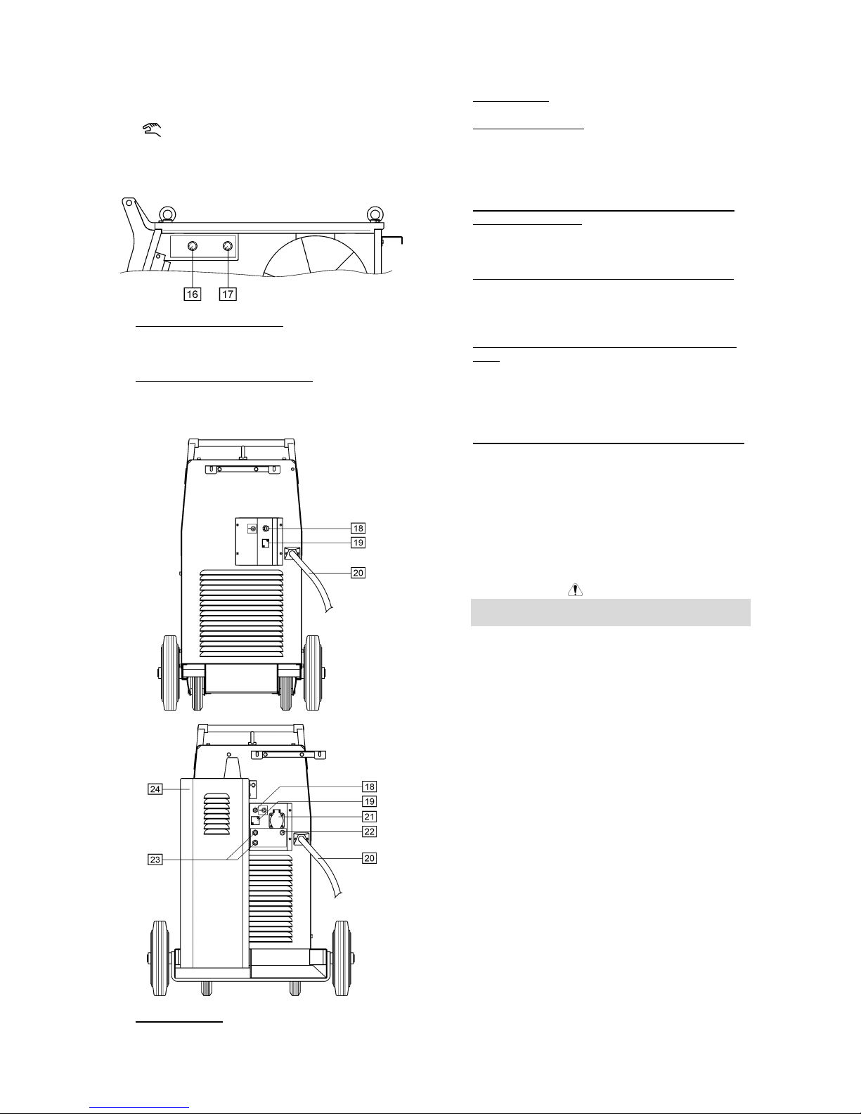
E-4
SYNERGIC
Si sélectionné, la machine fonctionne en
mode synergique (mode automatique).
Si sélectionné, la machine fonctionne en
mode manuel.
Sélectionner l’application désirée avec “le sélecteur
matériau et gaz Mix” [17].
16. Sélecteur de diamètre de fil: Sélectionner le
diamètre de fil utilisé pour votre application. Ce
réglage n’est utilisable qu’en mode synergique.
17. Sélecteur de matériau et gaz Mix: Ce réglage
sélectionne:
• Le matériau et le gaz de soudage.
• Le mode: manuel ou synergique.
18. Connecteur gaz: Pour le raccordement du tuyau
souple d’alimentation gaz.
19. Emplacement: Pour kit réchauffage CO2.
20. Câble d’alimentation: Il permet de raccorder la prise
de courant mâle au câble d’alimentation en fonction
de la réglementation électrique en vigueur. Seules
les personnes qualifiées sont habilitées à faire cette
connexion.
21. Prise d’alimentation refroidisseur (uniquement sur
modèle refroidi eau): Alimentation du refroidisseur.
en 230VAC, 2.5A protégée par disjoncteur [22].
Voir en [24] pour plus de détails.
22. Disjoncteur (uniquement sur modèle refroidi eau):
Protège la prise [21]. Il disjoncte lorsque l’intensité
dépasse 2.5A. Pour restituer l’alimentation,
appuyer dessus.
23. Raccords rapides (uniquement sur modèle refroidi
eau): Connexions des tuyaux d’eau. La torche de
soudage doit être connectée sur les raccords
rapides en façade de la machine. Le refroidisseur
[24] doit être connecté sur les raccords rapides à
l’arrière de la machine.
24. Refroidisseur (uniquement sur modèle refroidi eau):
Il refroidit l’eau venant de la torche de soudage. Il
est automatiquement on/off comme suit:
• Lorsque le soudage démarre, le refroidisseur
est automatiquement mis en marche.
• Lorsque le soudage s’arrête, le refroidisseur
continue de fonctionner pendant 5 min, puis il
est automatiquement arrêté.
• Si le soudage est redémarré pendant les 5 min,
le refroidisseur continue de fonctionner.
ATTENTION
Lire et comprendre le manuel d’instruction du
refroidisseur avant de le brancher.
Connections des câbles de soudage
Connecter le câble de masse soudage en [10] ou [11].
L’autre extrémité de ce câble doit être connectée à la
pièce à l’aide de la pince.
Branchez la torche sur l’euroconnecteur et vérifiez que
le tube contact et la gaine de la torche correspondent au
diamètre du fil et au matériau soudé.
Connexions des câbles de soudage
Ouvrir la porte de la machine.
Dévisser l’écrou rapide en bout d’axe.
Charger la bobine de fil de façon à ce qu’elle tourne
dans le sens horaire lorsque le fil est entraîné par l’unité
de dévidage.
S’assurer que l’ergot de l’axe est bien positionné dans le
trou du support bobine prévu à cet effet.
Replacer l’écrou rapide en bout d’axe.
Mettre en place les galets correspondant au diamètre du
fil.
Libérer le fil, couper le bout et s’assure qu’il n’est pas
mêlé.
Page 41

E-5
ATTENTION
Le bout de fil est pointu et peut blesser.
Introduire l’extrémité du fil dans l’ensemble de dévidage
jusqu’à l’euroconnecteur.
Ajuster la pression exercée sur les galets.
25. Axe.
26. Bobine de fil.
27. Fil.
28. Unité d’entraînement.
La machine est conçue pour des bobines de 15kg
(300mm).
Réglage du couple de freinage de l’axe
bobine
Pour éviter le jeu lorsque la bobine dévide le fil de
soudage, l’axe est pourvu d’un système de freinage.
Le réglage s’effectue en tournant la vis M10, située à
l’intérieur de l’armature de l’axe après avoir dévissé le
capuchon d’attache.
29. Vis de serrage.
30. Vis de réglage M10.
31. Ressort.
En tournant la vis M10 vers la droite, vous augmentez la
tension du ressort et vous pouvez accroître la couple de
freinage.
En tournant la vis M10 vers la gauche, vous diminuez la
tension du ressort et vous pouvez décroître la couple de
freinage.
Une fois le réglage achevé, vous devrez revisser le
capuchon.
Réglage de la pression du galet fou
Le réglage se fait en tournant la vis de réglage vers la
droite pour augmenter la pression et vers la gauche pour
la réduire.
ATTENTION
Si le réglage de la pression est trop faible, le fil va
patiner entre les galets. Si le réglage de la pression est
trop fort, le fil peut se déformer ce qui entraînerait des
problèmes de dévidage. La pression doit être
correctement réglée. Réduisez la pression lentement
jusqu’à ce que le fil commence à peine à glisser sur le
galet d’entraînement puis augmentez légèrement la
pression en donnant un tour à la vis de réglage.
Insertion du fil dans la Torche de
soudage
Connecter la torche à l’euroconnecteur, les
caractéristiques de la torche doivent être appropriées à
la puissance du générateur.
Mettre en marche le générateur (interrupteur
Marche/arrêt [1] en position “I” ).
Retirer le diffuseur de gaz et le tube contact du bout de
la torche.
Régler la vitesse de dévidage à 10 m/min avec le bouton
WFS [7].
Maintenir le sélecteur Avance à vide / Purge gaz [5] sur
Avance à vide jusqu'à la sortie du fil en bout de torche.
ATTENTION
Veillez à éloigner vos yeux et vos mains de l’extrémité
de la torche pendant le chargement du fil.
ATTENTION
Une fois l’enfilage du fil terminé, éteignez la machine
avant de remonter le tube contact et le diffuseur de gaz.
Alimentation gaz
Connectez le tuyau de gaz sur la prise alimentation gaz
située à l’arrière de la machine.
Fixez solidement la bouteille de gaz sur le support du
poste à l’aide de la chaîne.
Enlevez le capuchon d’étanchéité de la bouteille et fixez
le régulateur de pression.
Connectez le tuyau de gaz du poste sur le détendeur à
l’aide du collier de serrage.
Soudage MIG / MAG en mode Manuel
Pour commencer le soudage MIG /MAG en mode
manuel vous devez:
• Brancher la prise du câble d’alimentation à la prise
réseau.
• Mettre l’interrupteur M/A [1] en position marche (le
voyant est allumé).
• Faire passer le fil dans la torche au moyen de
l’interrupteur ”Cold Inch“ [5].
• Vérifier le débit de gaz torche au moyen de
l’interrupteur ”Gas Purge” [5].
• Positionner le sélecteur [17] sur mode Manuel
(vérifier que le voyant [15] indique le mode Manual).
• Rêgler la tension de soudage [3] et la vitesse de
dévidage WFS [7] en fonction du mode de soudage
et du matériau à souder. Le graphique suivant peut
Page 42
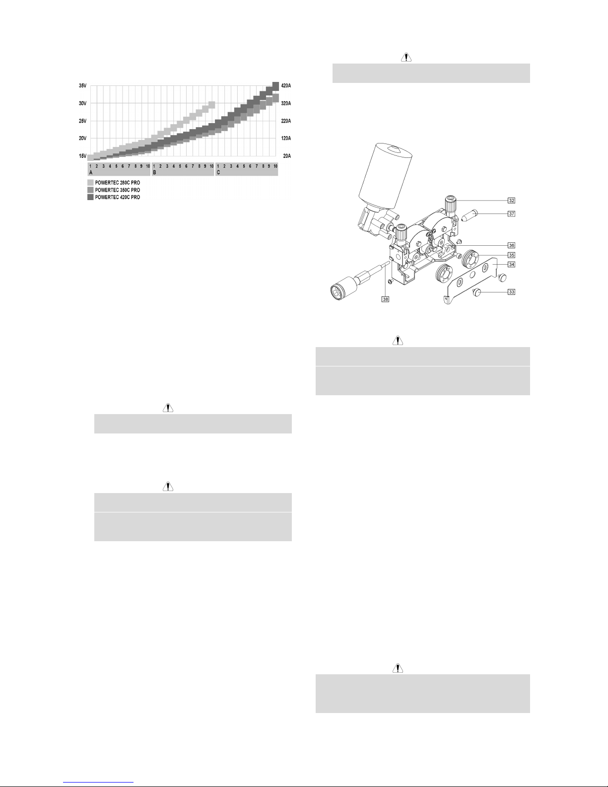
E-6
être utilisé pour la sélection de la tension de
soudage.
• Le soudage peut commencer.
Soudage MIG / MAG en mode
Synergique (automatique)
Pour commencer le soudage MIG /MAG en mode
synergique vous devez:
• Brancher la prise du câble d’alimentation à la prise
réseau.
• Mettre l’interrupteur M/A [1] en position marche (le
voyant est allumé).
• Faire passer le fil dans la torche au moyen de
l’interrupteur ”Cold Inch“ [5].
• Vérifier le débit de gaz torche au moyen de
l’interrupteur ”Gas Purge” [5].
• Positionner le sélecteur diamètre de fil [16] en
fonction du diamètre de fil utilisé.
• Positionner le sélecteur matériau et gaz mix [17] en
fonction du matériau à souder.
ATTENTION
Si vous utilisez un mode non synergique l’afficheur
A affiche “---“.
• En fonction du mode soudage et du matériau à
souder, sélectionner la tension de soudage à l’aide
des sélecteurs [3].
ATTENTION
Pour le soudage en mode synergique, la machine
sélectionne automatiquement une vitesse de
dévidage pour chaque position des sélecteurs [3].
La vitesse de dévidage automatique peut être
ajustée à ± 25% avec le bouton de réglage WFS [7].
• Le soudage peut commencer.
Changement des galets d’entrainement
La machine est livrée d’origine avec des galets
d’entrainement pour des fils de diamètre 1.0 et 1.2mm.
Pour les autres diamètres, utiliser les kits galets
appropriés (voir le chapitre accessoires pour la
commande des kits). La procédure de changement des
galets est la suivante:
• Arrêter la machine.
• Relever les leviers presseurs [32].
• Devisser les vis [33].
• Ouvrir le carter de protection [34].
• Changer les galets d’entrainement [35] en fonction
du diamètre de fil utilisé.
ATTENTION
Pour des fils de diamètre supérieur à 1.6mm, les
pièces suivantes doivent être changées:
• Les guide-fils [36] et [37].
• Le guide fil de l’euroconnecteur [38].
• Repositionner le carter de protection [34].
• Replacer les vis [33].
Maintenance
ATTENTION
Nous vous recommandons de contacter notre service
après-vente pour toute opération d'entretien ou
réparation. Toute intervention sur le poste effectuée par
des personnes non autorisées invalidera la garantie du
fabricant.
La fréquence des opérations de maintenance varie en
fonction de l’environnement de travail dans lequel la
machine est placée.
Tout défaut observé doit être immédiatement rapporté.
Maintenance
• Vérifier l’état des câble. Les remplacer si
nécessaire.
• Enlever les projections du bout de la torche. Ces
projections peuvent mofifier le flux du gaz
protecteur.
• Vérifier l’état de la torche. La remplacer si
nécessaire.
• Vérifier l’état et la fonctionnalité du ventilateur.
Maintenir les ouïes d’aération propres.
Maintenance périodique (toute les 200 heures
de fonctionnement ou au moins une fois par
an)
Faire la maintenace de routine et en plus:
• Nettoyer la machine. Utiliser de l’air comprimé
(basse pression), enlever la poussière externe et
toute poussière accessible.
• Vérifier le serrage des vis.
ATTENTION
L’alimentation principale doit être coupée avant toute
intervention de maintenance sur la machine. Après
chaque réparation, les tests de sécurité doivent être
faits.
Page 43

E-7
Compatibilité Electromagnétique (CEM)
11/04
Ce produit a été conçu conformément aux normes et directives relatives à la compatibilité électromagnétique des
appareils de soudage. Cependant, il se peut qu'il génère des perturbations électromagnétiques qui pourraient affecter le
bon fonctionnement d'autres équipements (téléphones, radios et télévisions ou systèmes de sécurité par exemple). Ces
perturbations peuvent nuire aux dispositifs de sécurité internes des appareils. Lisez attentivement ce qui suit afin de
réduire –voire d'éliminer– les perturbations électromagnétiques générées par cette machine.
Cette machine a été conçue pour fonctionner dans un environnement industriel. Pour une utilisation en
environnement domestique, des mesures particulières doivent être observées. L'opérateur doit installer et
utiliser le poste conformément aux instructions de ce manuel. Si des interférences se produisent,
l'opérateur doit mettre en place des mesures visant à les éliminer, avec l'assistance de Lincoln Electric si
besoin est.
Avant d'installer la machine, l'opérateur doit vérifier tous les appareils de la zone de travail qui seraient susceptibles de
connaître des problèmes de fonctionnement en raison de perturbations électromagnétiques. Exemples:
• Câbles d'alimentation et de soudage, câbles de commandes et téléphoniques qui se trouvent dans ou à proximité
de la zone de travail et de la machine.
• Emetteurs et récepteurs radio et/ou télévision. Ordinateurs ou appareils commandés par microprocesseurs.
• Dispositifs de sécurité. Appareils de mesure.
• Appareils médicaux tels que pacemakers ou prothèses auditives.
• L'opérateur doit s'assurer que les équipements environnants ne génèrent pas de perturbations électromagnétiques
et qu'ils sont tous compatibles. Des mesures supplémentaires peuvent s'avérer nécessaires.
• La taille de la zone de travail à prendre en considération dépend de la structure de la construction et des activités
qui s'y pratiquent.
Comment réduire les émissions?
• Connecter la machine au secteur selon les instructions de ce manuel. Si des perturbations ont lieu, il peut s'avérer
nécessaire de prendre des mesures comme l'installation d'un filtre de circuit par exemple.
• Les câbles de soudage doivent être aussi courts que possibles et attachés ensemble. La pièce à souder doit être
reliée à la terre si possible (s'assurer cependant que cette opération est sans danger pour les personnes et les
équipements).
• Le fait d'utiliser des câbles protégés dans la zone de travail peut réduire les émissions électromagnétiques. Cela
est nécessaire pour certaines applications.
• S'assurer que la machine est connectée à une bonne prise de terre.
Page 44

E-8
Caractéristiques Techniques
POWERTEC 280C, 350C & 420C PRO:
ALIMENTATION
Puissance absorbée
280C PRO:
12 kVA @ 40% FM
350C PRO:
16 kVA @ 40% FM
Tension d'alimentation
230 / 400V ± 10%
Triphasé
420C PRO:
21 kVA @ 40% FM
Fréquence
50 Hertz (Hz)
SORTIE NOMINALE A 40°C
Facteur de marche
(Basé sur une période de 10 min.)
Courant de soudage Tension de sortie
280C PRO:
40%
60%
100%
280A
230A
175A
28.0 Vdc
25.5 Vdc
22.8 Vdc
350C PRO:
40%
60%
100%
350A
285A
220A
31.5 Vdc
28.2 Vdc
25.0 Vdc
420C PRO:
40%
60%
100%
420A
345A
265A
35.0 Vdc
31.3 Vdc
27.3 Vdc
GAMME DE COURANT DE SORTIE
Gamme de courant de soudage Tension à vide max.
280C PRO:
30A - 280A
280C PRO:
39 Vdc
350C PRO:
30A - 350A
350C PRO:
42 Vdc
420C PRO:
30A - 420A
420C PRO:
49 Vdc
CABLES D'ALIMENTATION ET FUSIBLES
Fusible Câbles d'alimentation
280C PRO:
32A Fusion lente (230V)
20A Fusion lente (400V)
280C PRO:
4 Conducteurs, 4mm
2
350C PRO:
40A Fusion lente (230V)
25A Fusion lente (400V)
350C PRO:
4 Conducteurs, 4mm
2
420C PRO:
63A Fusion lente (230V)
32A Fusion lente (400V)
420C PRO:
4 Conducteurs, 6mm
2
DIMENSIONS
Poids
280C PRO:
142 kg
350C PRO:
147 kg
420C PRO:
157 kg
Hauteur
910 mm
Largeur
565 mm
700 mm
(version eau)
Longueur
1030 mm
420C PRO:
(version eau)
183 kg
Température de fonctionnement
-10°C à +40°C
Température de stockage
-25°C à +55°C
Page 45

F-1
Sikkerhetsregler
11/04
ADVARSEL
Dette utstyret skal kun brukes av kvalifisert personell. Forsikre deg om at all oppkobling, bruk, vedlikehold og reparasjon
er utført av kvalifisert personell. Les og forstå denne bruksanvisningen før utstyret tas i bruk. Hvis bruksanvisningen
ikke følges kan dette resultere i alvorlig personskade, død eller skade på utstyret. Les og forstå de følgende eksempler
og Advarsels- symboler. Lincoln Electric er ikke ansvarlig for skader som er forårsaket av: feil installasjon, dårlig
vedlikehold eller unormal bruk.
ADVARSEL: Dette symbolet indikerer at bruksanvisningen må følges for å unngå alvorlige
personskader, død eller skade på utstyret. Beskytt deg selv og andre fra personskade eller død.
LES OG FORSTÅ BRUKSANVISNINGEN: Les og forstå bruksanvisningen før utstyret tas i bruk.
Elektrisk buesveising kan være farlig. Hvis bruksanvisningen ikke følges kan dette resultere i alvorlig
personskade, død eller skade på utstyret
ELEKTRISK STØT KAN DREPE: Elektroden og arbeidstrykket (gods) står under spenning når
maskinen er slått på. Ikke berør disse deler med bar hud eller fuktige klær. Bruk hansker uten hull.
For å unngå fysisk kontakt til arbeidsstykket og gods/jord skal hele kroppsoverflaten være isolert ved
bruk av tørre klær. Ved halvautomatisk eller automatisk trådsveising er tråden, matehjul, sveisehode
og kontaktrør, under spenning. Sørg for at godskabelen har god kontakt til arbeidsstykket.
Tilkoblingen skal være så nær sveisestedet som mulig. Hold elektrodeholderen, godsklemme,
sveisekabel og sveisemaskin i god operativ stand. Reparer defekt isolasjon. Dypp aldri
elektrodeholderen i vann for avkjøling. Bruk sikkerhetsbelte når det arbeides over gulvnivå, for å sikre
mot fall som følge av elektriske støt.
ELEKTRISK UTSTYR: Husk alltid å slå av maskinen og koble fra nettspenningen når det skal utføres
arbeid på sveisemaskinen. Jording skal være iht. gjeldende regler.
ELEKTRISK UTSTYR: Hold elektrodeholderen, godsklemme, sveisekabel og sveisemaskin i god
operativ stand. Reparer defekt isolasjon. Dypp aldri elektrodeholderen i vann for avkjøling. Bruk
sikkerhetsbelte når det arbeides over gulvnivå, for å sikre mot fall som følge av elektriske støt.
ELEKTRISK OG MAGNETISK FELT KAN VÆRE FARLIG: Elektrisk strøm som flyter gjennom en
leder forårsaker elektromagnetiskfelt (EMF). Alle sveisere bør bruke følgende prosedyre for å
redusere eksponeringen av EMF. Legg elektroden og godskabelen sammen, tapes sammen hvis
mulig. Ikke kveil elektrodekabelen rundt kroppen. Ikke plasser deg mellom elektrodekabel og
godskabel. Godskabelen tilkobles så nær sveisestedet som mulig. Ikke arbeid nær
sveisestrømkilder.
CE GODKJENNING: Dette produktet er godkjent iht. Europeiske direktiver.
RØYK OG GASS KAN VÆRE FARLIG: Ved sveising kan det dannes helsefarlig røyk og gass.
Unngå å puste inn denne røyken og gassen. Bruk god ventilasjon og /eller punktavsug for å holde
røyken og gassen borte fra pustesonen. Når det sveises med elektroder som krever spesiell
ventilasjon, f.eks. rustfrie- og påleggselektroder, eller på bly -, sink- eller kadmiumbelagte stål og
andre metaller som avgir giftig røyk, er det særdeles viktig å benytte effektive avsug for å holde
forurensninger under tillatt grenseverdi (TLV-indeks) I små eller trange rom eller ved sveising på
særlig farlig materiale, kan det være aktuelt med gassmaske. Sveis ikke i områder nær klorert
hydrokarbondamp som kommer fra avfetting, rense- eller sprøyteoperasjoner. Varmen og stråler fra
lysbuen kan reagere med løsningsdamper og danne fosgen (en svært giftig gass), og andre
irriterende forbindelser. Beskyttelsesgass som brukes til sveising kan fortrenge luft og forårsake
ulykker eller død. Bruk alltid nok ventilasjon, spesielt i avgrenset område, slik at pusteluften er sikker.
Følg arbeidsgiverens sikkerhetspraksis.
STRÅLING FRA BUEN KAN SKADE: Stråling fra buen kan skade øynene og forårsake hudskade.
Benytt sveisemaske/hjelm med tilstrekkelig lysfiltergrad. Bør tilsvare EURO standard. Bruk
værneutstyr/klær av ikke brennbart materiale. Vær forsikret om at andre i arbeidsområder er beskyttet
mot stråling, sprut og varmt metall.
Page 46

F-2
SVEISESPRUT KAN FORÅRSAKE BRANN OG EKSPLOSJON: Brannfarlige ting i området tildekkes
for å hindre antennelse. Husk at sprut og varmt materiale fra sveising går lett igjennom små sprekker
og åpninger. Unngå sveising nær hydraulikkrør. Ha brannslokningsapparat klart. Følg
bruksanvisningen og sikkerhetsregler før bruk av gassbeholdere for å unngå farlige situasjoner. Vær
sikker på at ingen deler av elektrodekretsen berører arbeidsstykket eller jord når det ikke sveises.
Tilfeldig kontakt kan være årsaken til overoppheting og brannfare. Ved oppvarming, sveising eller
skjæring på tanker o.l., må man være sikker på at dette ikke fremkaller giftige eller antennbare
damper. Eksplosjon kan oppstå selv om tankene er ”renset”. Ventiler hult støpegods eller beholdere
før oppvarming, ved sveising eller skjæring kan de eksplodere. Sprut slynges ut fra buen, bruk oljefri
vernekledning slik som skinnhansker, solid forkle, bukser uten oppbrett, høye sko og lue over håret.
Bruk ørepropper ved sveising i stilling eller trange rom. Bruk alltid vernebriller med sidebeskyttelse.
Godskabelen tilkobles arbeidsstykket så nær sveisestedet som mulig. Hvis godskabelen tilkobles
metalldeler utenom sveisestedet, øker faren for overoppheting/antennelse og skade på utstyret.
SVEISTE MATERIALER KAN GI BRANNSKADE: Sveising genererer høy temperatur. Varme
materialer og overflater kan gi alvorlige brannskader. Bruk egnet verktøy og hansker når du skal
arbeide med varmt materiale.
SIKKERHETS MERKE: Dette utstyret er tilpasset for bruk i omgivelser hvor man har økt fare for
elektrisk støt.
GASSFLASKER KAN EKSPLODERE HVIS DE ER SKADET: Sjekk at beskyttelsesgassen og
gassregulatoren er riktig for sveiseprosessen. Alle slanger, fittings, etc. Må passe for utstyret og
være i god stand. Ha alltid gassflaskene i oppreist stilling og sikkert festet til en vogn, eller annen
stødig festeanordning. Gassflaskene skal være plassert vekk fra områder hvor de kan bli utsatt for
slag og i sikker avstand fra skjære-/sveisebue, gnister eller åpen flamme. Berør aldri gassflasken
med elektrodeholderen eller med annen gjenstand som står under spenning. Hold kroppen vekk fra
ventilutløpet når ventilen åpnes. Les og følg instruksjonene på gassflasken og tilhørende utstyr.
Installasjon og Brukerinstruksjon
Les hele denne manualen før maskinen tas i bruk.
Brukeren er ansvarlig for at installasjon og bruk av
utstyret gjøres iht. produsentens instruksjoner.
Plassering og omgivelser
Denne maskinen kan brukes under de fleste forhold,
men det er viktig at enkle forholdsregler følges for å sikre
lang levetid og pålitelig drift.
• Ikke plasser eller bruk denne maskinen på underlag
som heller 15° eller mer fra horisontalplanet.
• Maskinen skal ikke brukes til tining av frossene rør.
• Maskinen må plasseres der det er fri sirkulasjon av
ren luft, slik at luftstrømmen flyter fritt og ikke
hindres. Dekk ikke maskinen med papir, kluter eller
filler når den er i bruk.
• Støv og skitt som kan trekkes inn i maskinen bør
holdes på et minimum.
• Denne maskinen har beskyttelsesklasse IP23. Hold
maskinen tørr og beskyttet mot regn og snø, plasser
den aldri på et våt underlag eller i en dam.
• Plasser maskinen vekk fra utstyr som er
elektromagnetisk følsomt. Normal bruk kan påvirke
og skade elektronisk utstyr i umiddelbar nærhet.
Les avsnittet om Elektromagnetisk kompatibilitet.
• Maskinen bør ikke brukes i omgivelser med
temperatur høyere en 40°C.
Intermittens og overoppheting
Intermittensen på en sveisemaskine er målt i prosent av
tid, i en 10 minutters periode. Dette er tiden og amperen
man kan sveise med maskinen før den trenger en
pause.
Eksempel: 60% Intermittens:
Sveising i 6 minutter. Pause i 4 minutter.
Overskrides intermittensen på maskinen vil
termostatsikringen slå ut, og stoppe prosessen.
Transformatoren i denne strømkilden er beskyttet mot
overoppheting av en termostat. Hvis strømkilden skulle
bli overopphetet vil sveisestrømmen stoppe, og
maskinkontaktene vil stå uten strøm/spenning, samt at
kontrollampen for termostaten vil begynne å lyse. Når
temperaturen inne i strømkilden har falt til en akseptabel
temperatur vil kontrollampen slukke, og maskinen vil
fungere som normalt. NB. For sikkerhetsskyld vil det
ikke stå strøm/spenning på maskinkontaktene før
pistolavtrekkeren har blitt aktivert.
Minutter Eller senk
intermittensen
Nettilkobling
Nettledningen og støpselet skal være isolert og jordet
iht. gjeldene regler.
Kontroller at nettspenningen har rett volt, fase og
frekvens før maskinen tas i bruk. Den anbefalte
nettspenningen er angitt i avsnittet med: Tekniske
Page 47

F-3
spesifikasjoner, og på den tekniske platen på makinen.
Kontroller at nettstøpsel og kontakt er tilkoblet jord.
Maskinen kommer fra fabrikken koblet for 400V 3-fas.
For å koble om maskinen til 230V 3-fas 50Hz, se
avsnittet og figuren nedenfor.
Hvis det er nødvendig å endre nettspenningen på
strømkilden:
• Skru AV strømkilden med hovedbryteren, og trekk
ut nettledningen.
• Skru løs det store sidedekselet.
• Koble om panel X11 og X12 iht. figuren nedenfor.
X12
400V
X11
X12
230V
X11
• Skru på plass sidedekselet.
Sjekk at nettspenningen er tilstrekkelig for normal bruk
av maskinen. Den nødvendige størrelsen på nettsikring
og primærkabel finnes i avsnittet Teknisk data.
Viser til punkt [1] og [20] på illustrasjonen nedenfor.
Maskinkontakter
Viser til punkt [8], [10] og [11] på illustrasjonen nedenfor.
Betjeningsbrytere/Funksjoner
1. Hovedbryter og kontrollampe: Nå maskinen er
koblet til og skrudd PÅ, vil en kontrollampe begynne
å lyse for å indikere at strømkilden er PÅ og klar til
bruk.
2. Termostat kontrollampe: Denne kontrollampen vil
begynne å lyse når maskien er overopphetet og
prosessen har blitt stoppet. La maskinen være PÅ
og la kjøleviften kjøle ned maskinen. Når
kontrollampen slukker er maskinen klar til bruk.
3. Bryter for buespenning: POWERTEC 280C har 2
voltbrytere (2 og 10 trinns). POWERTEC 350C og
420C har 2 voltbrytere (3 og 10 trinns).
4. Bryter for 2-/4-takt: Denne velger 2-takt eller 4-takt
bryterbetjening. Bruken av 2-T/4-T er beskrevet
nedenfor:
↑
Pistolavtrekkeren trykket inn
↓
Pistolavtrekkeren sluppet ut
A. Sveisestrøm.
B. Burnback tid.
C. WFS Trådhastighet.
G. Dekkgass.
5. Bryter for kaldmating / gasspyling: Med denne
bryteren kan du kaldmate tråden, eller
gjennomspyle med dekkgass uten at det står
strøm/spenning på maskinkontaktene.
6. Knapp for justering av (run in) trådhastighet: Her
justeres hastigheten på tråden før den treffer platen.
Den kan justeres fra 0.5 til 1.0 av den innstilte
verdien satt på "Wire Feed Speed”
trådmatingshastigheten [7].
7. Knapp for WFS (Wire Feed Speed)
Trådmatingshastighet: Her stilles
trådmatingshastigheten for sveiseprosessen. Den
kan justeres fra 1.0 til 20m/min ved manuell
innstilling, eller den kan justere seg selv ±25% fra
innstilt verdi ved sveising med synergisk styring for
kompensasjon i buen.
8. Eurokobling: For tilkobling av sveisepistol.
9. Bryter for Burnback (trådutstikk): Denne bryteren
regulerer utstikket av tråd fra kontaktrøret etter
avsluttet sveising. Justeringsmulighet 8 til 250ms.
10. Maskinkontakt for høy Induktans: For tilkobling av
godskabel ved sveising i spraybue.
11. Maskinkontakt for Lav Induktans: For tilkobling av
godskabelen ved sveising i kortbue.
12. Terminal for bytte av polaritet: Her kan polariteten
på sveiseprosessen byttes mellom (+/-).
(Fabrikkinnstilling: “+” på sveisetråden).
Hvis det skal byttes polaritet bør du gjøre følgende:
• Skru AV strømkilden og koble ifra
nettledningen.
• Ta av terminaldekselet.
• Plasser laskene som vist på tegningen
nedenfor.
Page 48

F-4
• Sett på plass dekselet.
13. Display A: Viser faktisk sveisestrøm (i Ampere),
etter avsluttet sveising vil det vise gjennomsnitt
verdi i ca. 5s. Etter dette vil den vise innstillt
trådhastighet (WFS) (i m/min) - for manuell
innstilling eller ved synergi sveising hvor
matehastigheten kan justeres automatisk av
maskinen i et område fra 0.75-1.25 av innstillt verdi.
14. Display V: Viser faktisk buespenning (i Volt), etter
avsluttet sveising vil det vise gjennomsnitt verdi i ca.
5s. Etter dette vil det være blankt.
15. Lysdioder: Disse lampene vil vise innstillingene på
maskinen:
SYNERGIC
Når denne lampen lyser styres
sveiseprosessen Synergisk
(automatisk mode).
Når denne lampen lyser styres
sveiseprosessen Manuellt.
Velg de rette parameterne med knapp [17] "Welding
Material and Gas Mix Choice".
16. Tråddiameter Knapp: Med denne velges den
tråddiameteren som skal benyttes. Dette er kun
mulig med Synergisk styring.
17. Bryter for valg av program (Welding Material and
Gas Mix Choice): Med denne velges:
• Materialet det skal sveises på og dekkgassen
som skal benyttes.
• Manuell / synergisk styring.
18. Gassventil: For tilkobling av gasslangen fra
regulatoren.
19. Strømtilkobling: For gass-forvarmer.
20. Nettstøpsel: Sett på rett støpsel for den tiltenkte
spenning, strøm og fase. Dette skal kun gjøres av
godkjent personell.
21. Kontakt for kjøleaggregat (kun vannkjølt modelll):
For tilkobling av kjøleaggregatt. Kontakten har
230V, 2.5A og er beskyttet av sikringen [22]. Se
avsnitt [24] for flere detaljer.
22. Sikring (kun vannkjølt modell): Beskytter kontakten
[21]. Sikringen går hvis strømmen overskrider 2.5A.
Trykk den inn for å starte på nytt.
23. Hurtigkoblinger (kun vannkjølt modell): For
tilkobling av vannslanger. Sveisepistolen skal
kobles til hurtigkoblingene på fronten av maskinen.
Kjøleaggregatet [24] skal kobles til hurtigkoblingene
bak på maskinen.
24. Kjøleaggregat (kun vannkjølt modell): Kjøler
vannet til sveisepistolen. Skrues automatisk PÅ/AV
av strømkilden:
• Når det startes å sveise, starter kjøleaggregatet
automatisk.
• Når sveisingen stoppes vil kjøleaggregatet
fortsette å gå i ca. 5min., etter dette skrues det
automatisk AV.
• Hvis det startes å sveise igjen raskere enn de
5min., vil kjøleaggregatet gå kontinuerlig.
ADVARSEL
Les og forstå brukermanualen for kjøleaggregatet
før det taes i bruk.
Tilkobling av Sveiseutstyr
Stikk inn støpselet fra godskabelen i maskinkontakten
[10] eller [11] og vri rundt. Godsklemmen settes fast til
arbeidsstykket.
Koble så til sveisepistolen til eurokoblingen. Kontroller
at sveisepistolen er utstyrt med rett liner og kontaktrør
for den tiltenkte dimmensjonen sveisetråd.
Page 49

F-5
Montering av Sveisetråd
Åpen opp sidedekselet på trådmateren.
Skru AV spolefesteskruen på spolenavet.
Sett spolen på spolenavet slik at det roterer med
klokken.
Forsiker deg om at spolepinnen til spolebremsen er i
hullet på spolen.
Skru PÅ spolefesteskruen på spolenavet igjen.
Forsiker deg om at du har rett type matehjul og rett
spordiameter.
Ta løs tråden fra spolen og klipp av trådenden som er
bøyd med en avbiter.
ADVARSEL
Spiss tråd kan skade.
Roter spolen med klokken og tre tråden igjennom
mateverket og ut i eurokoblingen.
Juster matetrykket på trykkhjulene.
25. Spindel.
26. Trådspole.
27. Sveisetråd.
28. Mateverk.
Makinen kan ta opp til 15kg (300mm) spoler.
Justering av Spolebrems
For å forhindre at sveisetråden spinner seg av
trådspolen selv, er spindelen utstyrt med en spolebrems.
Justering skjer ved at man skrur på den M10 skruen som
er plassert i midten av spindelen, den er dekket av et
beskyttelsesdeksel som også må fjernes.
29. Beskyttelsesdeksel.
30. Justeringsskrue M10.
31. Trykkfjær.
Skru M10 justeringsskruen MED klokken og bremsen
går PÅ hardere, og holder igjen spolen mere.
Skru M10 justeringsskruen MOT klokken og bremsen
slipper OPP, og spolen glir lettere.
Etter justering husk å sette på plass
beskyttelsesdekselet.
Justere Matetykk
Matetrykket justeres ved at: justeringsmutteren skrues
MED klokken for økt matetrykk, og MOT klokken for
mindre matetrykk.
ADVARSEL
Hvis matetrykket er for lavt, vil matehjulet spinne på
tråden i mateverket og du får dårlig trådmating. Hvis
matetrykket er for høyt kan dette deformere tråden og du
får problemer med trådmatingen. Rett matetrykk får du
ved å slippe opp matetrykket slik at mateverket så vidt
begynner å spinne på tråden, så skrus
justeringsmutteren en runde.
Tråden Igjennom Mateverket
Monter rett type sveisepistol til eurokoblingen.
Strømtåligheten til sveisepistolen bør matche størrelsen
på sveisemaskinen.
Skru PÅ strømkilden med hovedbryteren [1] i “I”
posisjon).
Fjern gassmunnstykket og kontaktrøret fra
sveisepistolen.
Still inn trådmatingshastigheten til ca. 10m/min ( WFS)
med bryter [7].
Vipp på bryteren for kaldmating (Cold Inch / Gas Purge)
[5] og hold denne til tråden kommer ut av sveisepistolen.
ADVARSEL
Vær forsiktig, og hold sveisepistolen vekk fra ansiktet og
ikke ha hånden foran åpningen på svanehalsen når
sveisetråden kommer ut.
ADVARSEL
Når sveisetråden er ferdig matet igjennom
sveisepistolen, skru "AV" strømkilden før kontatktrør og
gassmunnstykke settes på plass.
Dekkgass og Tilkobling
Koble til gasslangen til gassventilen som sttter på
bakplaten på maskinen.
Sett gassflasken på plattformen og sikre denne med
kjettingen som følger maskinen.
Fjern støvhetten fra gassflasken og monter
gassregulatoren til gassflasken.
Skru fast gasslangen fra maskinen til gassregulatoren på
gassflasken.
Sveising med MIG / MAG metoden og
manuell innstilling
For å starte å sveise MIG/MAG med manuell innstilling
av sveiseparameterne bør du:
• Koble nettledningen med rett støpsel til
nettspenningen.
Page 50

F-6
• Skru PÅ strømkilden med hovedbryteren [1] (den
skal begynne å lyse).
• Få tråden igjennom sveisepistolen med ”Cold Inch“
bryteren [5].
• Sjekke dekkgassen med ”Gas Purge” bryteren [5].
• Sette bryteren [17] i Manuell posisjon (kontroller at
lysdioden [15] har tent for Manual mode).
• Still inn rett buespenning ihht. Materialtykkelse og
sveisemetode med bryter [3] og trådhastigheten
med bryteren (WFS) [7]. Bruk skjemaet nedenfor til
rett valg av sveiseparametere:
• Følg gjeldende lover og regler. Du kan nå begynne
og sveise. Lykke til!
Sveising med MIG / MAG metoden og
Synergisk (automatisk) styring
For å begynne å sveise med MIG/MAG metoden og
synergisk styring bør du:
• Koble nettledningen med rett støpsel til
nettspenningen.
• Skru strømkilden PÅ med hovedbryteren [1] (den
skal begynne å lyse).
• Få tråden igjennom sveisepistolen med ”Cold Inch“
bryteren [5].
• Sjekke dekkgassen med ”Gas Purge” bryteren [5].
• Sette bryteren [16] i den possisjonen som er riktig
ihht. Den diameter tråd som skal benyttes.
• Sette bryteren [17] i den possisjonen som er rett for
materiale og dekkgasstypen som skal benyttes.
ADVARSEL
Hvis den valgte sveiseprosessen ikke har
synergistyring, vil tre horisontale streker vises i
display “A”.
• Velg rett buespenning ihht. Den materialtykkelsen
og sveisemetoden som er valgt med bryter [3].
ADVARSEL
Ved synergisk sveising vil maskinen automatisk
velge den rette trådhastigheten basert på den valgte
buespenningen med bryter [3]. Den automatiske
trådhastigheten kan trimmes ±25% med (WFS)
knappen [7].
• Følg gjeldende lover og regler. Du kan nå begynne
og sveise. Lykke til!
Bytte av Matehjul
Maskinen blir levert med matehjulene 1.0 og 1.2mm.
For andre dimmensjoner finnes det andre matehjul å få
kjøpt. Se avsnittet tilleggsutstyr. For bytte av matehjul:
• Skru strømkilden AV.
• Vipp ut trykkarmen på mateverket [32].
• Skru løs festeskruene [33].
• Åpne beskyttelsesdekselet [34].
• Bytt matehjulene [35] til den dimmensjonen tråd
som skal benyttes.
ADVARSEL
For tråddiametere større enn 1.6mm, må følgende
deler byttes ut:
• Trådføringer inn [36] og [37] trådfører ut.
• Trådføringsrøret i Eurokoblingen [38].
• Sett på plass og fest beskyttelseslokket [34] til
matehjulene.
• Skru lokket fast med skruene [33].
Vedlikehold
ADVARSEL
For vedlikehold og/eller reparasjoner kontaktes Lincoln
Electric, eller et godkjent Lincoln Electric
serviceverksted. Dersom service og/eller reparasjoner
utføres av ikke autorisert personale eller –verksted
dekkes dette ikke av Lincoln Electric garantibetingelser.
Frekvensen på vedlikeholdet av maskinen er avhenging
av hvor mye den benyttes og av miljøet maskinen står i.
Skader på maskinen bør repareres umiddelbart.
Daglig vedlikehold
• Sjekk alle kabler og koblinger og bytt disse hvis
nødvendig.
• Fjern sveisesprut fra gassmunnstykket på
sveisepistolen. Sveisespruten kan hindre
dekkgassen fra å nå smeltebadet.
• Sjekk sveisepistolen og delene. Bytt deler eller
pistol hvis nødvendig.
• Kontroller at kjøleviften går og at luften har fri flyt
igjennom luft inn/uttak.
Periodisk vedlikehold (hver 200 arbeidstimer
eller alltid1 gang I året)
Utfør den dagligen vedlikeholdsrutinen og i tillegg:
• Tørk av maskinen og blås med tørr trykkluft med
lavt trykk. Blås også rent inne i kabinettett.
• Kontroller og trekk til alle skruer.
ADVARSEL
Trekk ut nettledningen når vedlikehold/ service skal
utføres. Etter hver reperasjon kontroller at alt virker og
er i orden.
Page 51

F-7
Elektromagnetisk Kompatibilitet (EMC)
11/04
Dette produktet er produsert i samsvar med EU-direktiver / normer for Elektromagnetisk Kompatibilitet EMC.
Elektromagnetisk stråling kan påvirke mange elektroniske utstyr; annet nærliggende sveiseutstyr, radio- og TVmottagere, numerisk styrte maskiner, telefonsystemer, datamaskiner etc. Når strålingen blir mottatt av annet utstyr, kan
denne strålingen forstyrre utstyret. Les og forstå dette avsnittet for å redusere eller eliminere elektromagnetiske
strålinger forårsaket av dette utstyret.
Denne maskinen har blitt laget for bruk i et Industrielt miljø. Vær oppmerksom på at det kan oppstå
forstyrrelser fra sveise- eller skjærestrømkilden og ekstra tiltak kan bli nødvendige når strømkilden brukes i
privathus o.l. Brukeren er ansvarlig for installasjon og bruk av utstyret gjøres iht. produsentens
instruksjoner. Hvis elektromagnetiske forstyrrelser oppdages er det brukeren av sveiseutstyret som har
ansvaret for å løse problemet, med teknisk assistanse fra produsenten. Modifiser ikke dette utstyret uten godkjennelse
fra Lincoln Electric.
Før installasjon av sveiseutstyret, skal brukeren foreta en vurdering av potensialet for elektromagnetiske problemer i
nærliggende områder. Vurder følgende:
• Andre tilførselskabler, kontrollkabler, signaler- og telefonkabler; over, under og i nærheten av sveisestrømkilden.
• Radio, TV sender og mottaker. Datamaskiner og kontrollutstyr.
• Kritisk sikkerhetsutstyr, dvs. Sikring av industri. Utstyr for kalibrering av måleinstrumenter.
• Helsen til folk omkring; dvs. Brukere av pacemaker; høreapparater.
• Immuniteten til andre apparater i området. Brukeren skal forsikre seg om at sveiseutstyret kan samkjøres (er
kompatibelt) med annet utstyr i området. Det kan da være nødvendig med ekstra sikkerhetstiltak.
• Tid på dagen som sveisingen eller andre aktiviteter, skal foregå. Størrelsen av omliggende område avhenger av
utførelsen av bygningen og andre aktiviteter som finner sted der omliggende område kan stekke seg utenfor
avgrensningen av lokalitetene.
Metoder for redusering av elektromagnetisk stråling fra maskinen.
• Sveiseutstyret skal kobles til nettet iht. produsentens anbefalinger. Hvis forstyrrelser oppstår kan det være
nødvendig med ekstra tiltak, f.eks. installering av nettfilter. Det bør overveies å skjerme nettledningen i metallfolie
o.l. for permanent installert utstyr.
• Kablene skal holdes så korte som mulig, og legges så nær hverandre, og så nær gulvet som mulig. En
sammenkobling til jord kan redusere stråling i noen tilfeller, men ikke bestandig. En bør prøve å unngå jording av
arbeidsstykket, da jordingen vil øke risikoen for uhell for operatøren, eller ødeleggelse av annet utstyr.
• Selektiv skjerming og beskyttelse av andre kabler og utstyr i omkringliggende områder kan redusere problemer med
forstyrrelser. Dette kan være nødvendig ved spesielle applikasjoner.
Page 52

F-8
Tekniske Spesifikasjoner
POWERTEC 280C, 350C & 420C PRO:
NETTSIDE
Belastning ved intermittens
280C PRO:
12 kVA @ 40% Intermittens
350C PRO:
16 kVA @ 40% Intermittens
Nettspenning
230 / 400V ± 10%
3-fas
420C PRO:
21 kVA @ 40% Intermittens
Frekvens
50 Hertz (Hz)
SVEISEKAPASITET VED 40°C
Intermittens
(Basert på en 10 min. periode)
Sveisestrøm Buespenning
280C PRO:
40%
60%
100%
280A
230A
175A
28.0 Vdc
25.5 Vdc
22.8 Vdc
350C PRO:
40%
60%
100%
350A
285A
220A
31.5 Vdc
28.2 Vdc
25.0 Vdc
420C PRO:
40%
60%
100%
420A
345A
265A
35.0 Vdc
31.3 Vdc
27.3 Vdc
SVEISESIDE
Strømområde Tomgangsspenning
280C PRO:
30A - 280A
280C PRO:
39 Vdc
350C PRO:
30A - 350A
350C PRO:
42 Vdc
420C PRO:
30A - 420A
420C PRO:
49 Vdc
ANBEFALTE KABELSTØRRELSER OG SIKRINGER
Nettsikring Nettkabel
280C PRO:
32A treg (230V nettspenning)
20A treg (400V nettspenning)
280C PRO:
4 leder, 4mm
2
350C PRO:
40A treg (230V nettspenning)
25A treg (400V nettspenning)
350C PRO:
4 leder, 4mm
2
420C PRO:
63A treg (230V nettspenning)
32A treg (400V nettspenning)
420C PRO:
4 leder, 6mm
2
DIMENSJONER
Vekt
280C PRO:
142 kg
350C PRO:
147 kg
420C PRO:
157 kg
Høyde
910 mm
Bredde
565 mm
700 mm
(Vannkjølt)
Lenge
1030 mm
420C PRO:
(Vannkjølt):
183 kg
Driftstemperatur
-10°C to +40°C
Lagringstemperatur
-25°C to +55°C
Page 53

G-1
Veiligheid
11/04
WAARSCHUWING
Deze apparatuur moet gebruikt worden door gekwalificeerd personeel. Zorg ervoor dat installatie, gebruik, onderhoud
en reparatie alleen uitgevoerd wordt door gekwalificeerd personeel. Lees en begrijp deze gebruiksaanwijzing alvorens te
lassen. Negeren van waarschuwingen en aanwijzingen uit deze gebruiksaanwijzingen kunnen lijden tot verwondingen,
letsel, dood of schade aan het apparaat. Lees en begrijp de volgende verklaringen bij de waarschuwingssymbolen.
Lincoln Electric is niet verantwoordelijk voor schade veroorzaakt door verkeerde installatie, slecht onderhoud of
abnormale toepassingen.
WAARSCHUWING: Dit symbool geeft aan dat alle navolgende instructies uitgevoerd moeten worden
om letsel, dood of schade aan de apparatuur te voorkomen. Bescherm jezelf en anderen tegen letsel.
LEES EN BEGRIJP DE INSTRUCTIES: Lees en begrijp deze gebruiksaanwijzing alvorens het
apparaat te gebruiken. Elektrisch lassen kan gevaarlijk zijn. Het niet volgen van de instructies uit
deze gebruiksaanwijzing kan letsel, dood of schade aan de apparatuur tot gevolg hebben.
ELEKTRISCHE STROOM KAN DODELIJK ZIJN: Lasapparatuur genereert hoge spanning. Raak
daarom de elektrode, werkstukklem en aangesloten werkstuk niet aan. Isoleer jezelf van elektrode,
werkstukklem en aangesloten werkstukken.
ELEKTRISCHE APPARATUUR: Schakel de voedingsspanning af m.b.v. de schakelaar aan de
zekeringkast als u aan de machine gaat werken. Aard de machine conform de nationaal (lokaal)
geldende normen.
ELEKTRISCHE APPARATUUR: Controleer regelmatig de aansluit-, de las- en de werkstukkabel.
Vervang kabels waarvan de isolatie beschadigd is. Leg de elektrodehouder niet op het werkstuk of
een ander oppervlak dat in verbinding met de werkstukklem staat om ongewenst ontsteken van de
boog te voorkomen.
ELEKTRISCHE EN MAGNETISCHE VELDEN KUNNEN GEVAARLIJK ZIJN: Elektrische stroom,
vloeiend door een geleider, veroorzaakt een lokaal elektrisch- en magnetisch veld (EMF). EMFvelden kunnen de werking van pacemakers beïnvloeden. Personen met een pacemaker dienen hun
arts te raadplegen alvorens met lassen te beginnen.
CE OVEREENSTEMMING: Deze machine voldoet aan de Europese richtlijnen.
ROOK EN GASSEN KUNNEN GEVAARLIJK ZIJN: Lassen produceert rook en gassen die gevaarlijk
voor de gezondheid kunnen zijn. Voorkom inademing van rook of gassen. Om deze gevaren te
voorkomen moet er voldoende ventilatie of een afzuigsysteem zijn om de rook en gassen bij de lasser
vandaan te houden.
BOOGSTRALING KAN VERBRANDING VEROORZAKEN: Gebruik een lasscherm met de juiste
lasglazen om de ogen te beschermen tegen straling en spatten. Draag geschikte kleding van een
vlamvertragend materiaal om de huid te beschermen. Bescherm anderen in de omgeving door
afscherming van de lasboog en vertel dat men niet in de lasboog moet kijken.
LASSPATTEN KUNNEN BRAND OF EXPLOSIE VEROORZAKEN: Verwijder brandbare stoffen uit
de omgeving en houdt een geschikte brandblusser paraat.
AAN GELASTE MATERIALEN KUNT U ZICH BRANDEN: Lassen genereert veel warmte. Aan hete
oppervlakken en materialen in de werkomgeving kunt u zich lelijk branden. Gebruik handschoenen en
tangen om werkstukken en materialen in de werkomgeving vast te pakken of te verplaatsen.
VEILIGHEIDSMARKERING: Deze machine is geschikt voor gebruik als voedingsbron voor lasstroom
in omgevingen met een verhoogd risico en kans op elektrische aanraking.
Page 54

G-2
GASFLESSEN KUNNEN EXPLODEREN BIJ BESCHADIGING: Gebruik alleen gasflessen die het
juiste beschermgas voor uw lasproces bevatten en gebruik bijbehorende reduceerventielen. Houd
gasflessen altijd verticaal en zet ze vast op een onderstel of andere daarvoor geschikte plaats.
Verplaats of transporteer geen flessen zonder kraanbeschermdop. Voorkom dat elektrode,
elektrodehouder of andere elektrisch hete delen in aanraking komen met de fles. Plaats flessen
zodanig dat geen kans bestaat op omverrijden of blootstelling aan andere materiële beschadiging en
een veilige afstand tot las- of snijdwerkzaamheden en andere warmtebronnen, vonken of spatten
gewaarborgd is.
Installatie en Bediening
Lees dit hoofdstuk geheel alvorens de machine te
instaleren of te gebruiken.
Plaats en omgeving
Deze machine werkt onder zware omstandigheden.
Enkele eenvoudige voorzorgsmaatregelen garanderen
een betrouwbare werking en lange levensduur.
• Plaats de machine niet op een ondergrond die meer
dan 15° uit het lood ligt (van horizontaal).
• Gebruik deze machine niet voor het ontdooien van
waterleidingen.
• Plaats de machine daar waar er een vrije circulatie
van schone lucht is, zonder beperking van de
uitgaande lucht vanuit de ventilatieopeningen.
Bedek de ingeschakelde machine niet met papier,
doek of iets dergelijks.
• Beperk het opzuigen van stof en vuil tot een
minimum.
• Deze machine heeft een IP23 beschermingsgraad.
Houdt de machine zo mogelijk droog en plaats hem
niet op vochtige grond of in plassen.
• Plaats de machine zo mogelijk weg van radio-
bestuurde apparatuur. Normaal gebruik kan de
werking van dichtbijzijnde radiobestuurde
apparatuur negatief beïnvloeden, met ongevallen of
schade tot gevolg. Lees het hoofdstuk
Elektromagnetische Compatibiliteit van deze
gebruiksaanwijzing.
• Niet gebruiken in ruimtes met een
omgevingstemperatuur van 40°C of hoger.
Inschakelduur en oververhitting
De inschakelduur van de machine komt overeen het
percentage van de tijd dat een lasser de machine kan
gebruiken bij een aangegeven lasstroom.
Voorbeeld: 60% inschakelduur:
6 minuten lassen. 4 minuten pauze.
Excessieve verlenging van de inschakelduur activeerd
het thermisch beveiligings circuit.
De lastransformator in de machine beschermd tegen
oververhitting door middel van een thermostaat.
Wanneer de machine oververhit raakt, schakelt de
lasstroom “UIT“ en de indicatielamp van de thermische
beveiliging gaat “AAN”. Wanneer de machine tot een
veilige bedrijfstemperatuur afgekoeld is, gaat de
Indicatielamp uit en de machine is gereed voor normaal
gebruik. Let op: uit veiligheidsredenen kan de machine
niet uit de thermische beveiligingscyclus komen als de
toortsschakelaar niet losgelaten wordt.
Minuten Of verlaag de
inschakelduur
Primaire aansluiting
Installatie en primaire stekkerdoos moet volgens lokaal
geldende normen aangelegd worden.
Controleer voedingsspanning,aantal fasen en
netfrequentie alvoerens de machine in te schakelen.
Verzeker u ervan dat de machine goed geaard is.
Toegestaane voedingsspanningen zijn 3x230V en
3x400V 50Hz (400V: standaard fabrieksinstelling).
Indien het noodzakelijk is de primaire voedingsspanning
te veranderen:
• Verzeker u ervan dat de primaire kabel uit de
stekkerdoos is genomen en de machine
uitgeschakeld is.
• Verwijder het grote zijpaneel van de machine.
• Wijzig de aansluitingen van t X11 en X12 zoals
hieronder aangegeven.
X12
400V
X11
X12
230V
X11
• Plaats het grote zijpaneel.
Verzeker u ervan dat de primaire aansluiting voldoende
vermogen kan leveren voor normale werking van de
machine. Maak gebruik van trage zekeringen (of
zekeringsautomaten met een ”D” karateristiek) en kabel
met voldoende aderdoorsnede zoals aangegeven in de
technische specificaties van deze gebruiksaanwijzing.
Zie ook punten [1] en [20] van de afbeeldingen
hieronder.
Aansluitingen
Zie punten [8], [10] en [11] van onderstaande afbeelding.
Page 55

G-3
Bediening en Functies
1. Primaire schakelaar en “Aan” lamp: Nadat de
machine ingeschakeld is met de primaire
schakelaar, gaat de “Aan” lamp brande ten teken
dat de machine bedrijfsgereed is.
2. Thermische Overbelasting Indicator: Deze lamp
gaat branden wanneer de machine oververhit is en
de Lasstroom uitgeschakelt is. Laat de machine
ingeschakelt om de interne componenten te laten
afkoelen. De machine is weer klaar voor gebruik
wanneer de lamp uit is.
3. Stappenschakelaars Lasspannings: POWERTEC
280C heeft 2 schakelaars (2 en 10 stappen). De
POWERTEC 350C en 420C hebben 2 schakelaars
(3 en 10 stappen).
4. 2/4 takt schakelaar: Maakt een functiekeuze
mogelijk voor de toortsschakelaar. De functionaliteit
van de 2T/4T mode is beneden aangegeven:
↑
Toortsschakelaar ingedrukt
↓
Toortsschakelaar losgelaten
A. Lasstroom.
B. Afbrandvertraging.
C. Draadsnelheid.
G. Gas.
5. Koude Draadaanvoer / Gas Spoelen: Deze
schakelaar maakt draadaanvoer of gasspoelen
mogelijk zonder lasspanning.
6. Regelaar Startsnelheid Lasdraad: Maakt het
mogelijk de draadaanvoersnelheid te regelen voor
het lassen tussen 0.5 tot 1.0 van de waarde van de
draadsnelheid zoals deze is ingesteld met de
“Regelaar Draadsnelheid” [7].
7. Regelaar Draadsnelheid WFS (Wire Feed Speed):
Voor volledige controle over de draadsnelheid
tussen 1.0 tot 20m/min in manual modus of voor
correctie ±25% van de automatisch door de
machine ingestelde lassnelheid in synergische
modus.
8. EUROconnectort: Voor aansluiting van de lastoorts.
9. Knop Afbrandvertraging: Maakt het mogelijk de
gewenste uitsteek van de lasdraad na het stoppen
met lassen in te stellen. Het regelbereik loopt van 8
tot 250ms.
10. Dinse Connector met Veel Smoorspoel (Hoge
Inductie): Voor aansluiting werkstukkabel
11. Dinse Connector met Weinig Smoorspoel (Lage
Inductie): Voor aansluiting werkstukkabel
12. Aansluitingen Voor Wissellen Laspolariteit: Biedt de
keuze te wissellen van polariteit (+/-), welke zit aan
de lastoorts (fabrieksinstelling: “+” aan de lastoorts).
Wanneer het noodzakelijk is de polariteit te wisselen
moet men de volgende stappen uitvoeren:
• Schakel de machine uit en verwijder de stekker
uit de stekkerdoos.
• Verwijder de beschermkap van de
aansluitstrips.
• Plaats de strips overeenkomstig met de
onderstaande afbeelding.
• Plaats de beschermkap.
13. Display A: Toont de actuele lasstroom (in A), en na
het lassen toont de meter de gemiddelde lasstroom
gedurende 5 seconden. Na deze tijd toont de meter
de waarde van de draadsnelheid (in m/min) - in
manuele modus of de correctie van de automatisch
ingestelde waarde van de machine in synergic
mode tussen 0.75-1.25.
14. Display V: Toont de actuele waarde van de
lasspanning (in V), en na het lassen toont de meter
de gemiddelde lasspanning gedurende 5 seconden.
Na deze tijd geeft het display niets aan.
15. Indicators Werking: Deze lampjes geven de
werkmodus van de machine aan:
SYNERGIC
Wanneer deze brand werkt de
machine in Synergische modus
(automatische modus).
Wanneer deze brandt werkt de
machine in Manuele modus.
Page 56

G-4
Kies de gewenste materiaalsoort met de
"Lastoevoegmateriaal en Gassoort knop" [17].
16. Knop Draad Diameter: Biedt een voorkeuze voor
de gewenste draaddiameter voor het gewenste
lasproces. Deze functie werkt alleen in de
synergische modus.
17. Knop Lastoevoegmateriaal en Gassoort: Deze
knop wordt gebruikt om een keuze te maken tussen:
• De te lassen materialen en de bijbehorende
gassoort.
• Manuele / synergische modus.
18. Wartel: Voor aansluiting gasslang.
19. Afgedekte Opening: Voor CO2 gas verwarmer.
20. Primaire kabel: Sluit een passende stekker aan die
past bij de gevraagde primaire stroom en geldende
normen. Alleen gekwalificeerde techici mogen deze
stekkers aansluiten.
21. Stekkerdoos Waterkoeler (Alleen voor
watergekoelde modellen): Voedt de waterkoeler.
De stekerdoos heeft een aansluitwaarde van 230V,
2.5A en is voorzien van een thermische beveiliging
[22]. Zie ook punt [24] voor meer details.
22. Thermische Beveiliging (Alleen voor watergekoelde
modellen): Beschermt de primaire voeding van de
waterkoeling [21]. Deze schakelt de voeding af
wanneer de opgenomen stroom boven de 2.5A
komt. Indrukken om deze te resetten na uitval.
23. Snelkoppelingen (Alleen voor watergekoelde
modellen): Voor aansluiten waterslangen. De
wateraansluiting van de lastoorts moeten
aangesloten worden op het voorpaneel van de
machine. De waterkoeler [24] moet aangesloten
worden op de snelkoppelingen op de achterzijde
van de machine.
24. Waterkoeler (Alleen voor watergekoelde modellen):
Koelt de watergekoelde lastoorts. Deze wordt
automatisch in - en uitgeschakelt door de machine:
• Wanneer er gestart wordt met lassen, wordt de
Waterkoeler automatisch gestart.
• Na het stoppen met lassen loopt de
Waterkoeler nog 5 minuten, daarna wordt de
koeler automatisch uitgeschakelt.
• Indien er een herstart binnen deze 5minuten
plaats vindt, blijft de koeler lopen.
WAARSCHUWING
Lees en Begrijp de gebruiksaanwijzing van de
waterkoeler alvorens deze op de machine aan te
sluiten.
Aansluitingen Laskabels
Steek de stekker van de werkstukkabel in de
stekkerdoos [10] of [11]. Verbindt het andere einde van
de werkstukkabel aan het werkstuk.
Sluit een passend laspistool met euroconnector aan op
de euroconnector. Zorg ervoor dat Liner en Tip behoren
bij de gebruikte lasdraad en diameter.
Invoeren Lasdraad
Open het zijpaneel van de machine.
Neem de moer van de haspeldrager.
Schuif de haspel op as, zodanig dat de haspel met de
klok meedraait wanneer de draad in het
draadaanvoersysteem wordt gevoed.
Zorg ervoor dat de Pen van de haspeldrager in de
uitsparing van de Haspel / Adapter valt.
Plaats de borgmoer van de haspeldrager.
Gebruik de juiste draadaanvoerrol voor de bijbehorende
draadsoort / draaddiameter.
Page 57

G-5
Maak het einde van de lasdraad los van de haspel, knp
het eestre stukje af en zorgervoor dat er geen knikken in
de draad zitten.
WAARSCHUWING
Het scherpe eind van de draad kan verwonding
veroorzaken.
Draai haspel met de klok mee en voer de draad in, in het
draadaanvoersysteem tot aan de Euroconnector.
Stel de juiste kracht in van de aandrukrollen.
25. Adapter.
26. Draadhaspel (spoel).
27. Lasdraad.
28. Draadaanvoerunit.
Machine is geschikt voor 15kg (300mm) spoelen.
Afstellen rem haspelas
Om spontaan en ongewenst afrollen van de lasdraad te
voorkomen is de haspelas voorzien van een rem.
Afstellen van de rem is mogelijk door het draaien aan de
M10 schroef die aan de binnenzijde van de as geplaatst
is. Zichtbaar na verwijderen van de bevestigings schroef
van de as.
29. Bevestigings schroef.
30. Afstelschroef M10.
31. Drukveer.
Door de schroef met de klok mee te draaien neemt de
veerdruk toe en wordt de remkracht hoger.
Door de schroef tegen de klok in te draaien neemt de
veerdruk en ook de remkracht af.
Na afstelling kan men de bevestiging schroef weer
bevestigen.
Afstellen druk draadaanvoerrol
De drukkracht is af te stellen door de afstelschroef te
draaien. Met de klok mee draaien geeft een hogere
draaddruk, tegen de klok draaien geeft een lagere druk.
WAARSCHUWING
Als de draaddruk te laag is slipt de draadaanvoerrol over
de lasdraad. Als de draaddruk te hoog is bestaat de
kans op vervorming van de lasdraad, wat op zijn beurt
weer draadaanvoerproblemen veroorzaakt in het
laspistool. De juiste druk moet ingesteld worden.
Verminder de druk geleidelijk totdat de draad juist begint
te slippen. Draai vervolgens de afstelmoer één slag met
de klok mee om de druk weer op de voeren.
Invoeren van lasdraad in de toorts
Sluit een passende lastoorts aan op de machine. De
specificaties van de lastoorts moeten overeen komen
met de lasmachine.
Schakel de stroombron in (de hoofdschakelaar [1] in “I”
positie).
Verwijder de gasverdeler en contact tip van de lastoorts.
Stel de draadsnelheid in op ongeveer 10m/min met de
draadsnelheid (WFS) knop [7].
Schakel de knop Koude draadaanvoer / Gas Spoelen [5]
in de positie “Koude draadaanvoer” en houdt deze in
deze positie totdat de lasdraad uit het laspistool komt.
WAARSCHUWING
Houd ogen en hand ver van einde van het laspistool
gedurende draadaanvoer.
WAARSCHUWING
Wanneer er voldoende lasdraad uit het pistool komt
moet de machine uitgeschakeld worden alvorend de
gasverdeler en contacttip weer te plaatsen.
Gas voorziening
Sluit de gasslang aan op de gasconnector op de
achterzijde van de machine.
Plaats de gascilinder op de flessendrager en borg deze
met de ketting.
Plaats een passend reduceerventiel op de gascilinder.
Sluit de gasslang vervolgens aan op het reduceerventiel.
MIG / MAG lassen in Manuele modus
Om te lassen in de manuele MIG/MAG methode moet
men:
• De netstekker in de stekkerdoos steken.
• Schakel de machine in met de Aan/Uit schakelaar
[1]. (de lamp moet branden).
• Voer de lasdraad in de toorts in met behulp van de
schakelaar “koude draadaanvoer” [5].
• Controleer de gasstroom met behulp van de
schakelaar “gas spoelen” [5].
• Zet knop [17] in de Manuele positie (controleer of de
lamp [15] brandi in Manuele modus).
• Stel de juiste lasspanning behorend bij het gekozen
lasmateriaal en werkstukdikte met behulp van
schakelaars [3] en de draadaanvoersnelheid met de
draadsnelheidsknop (WFS) knop [7]. Onderstaand
Page 58
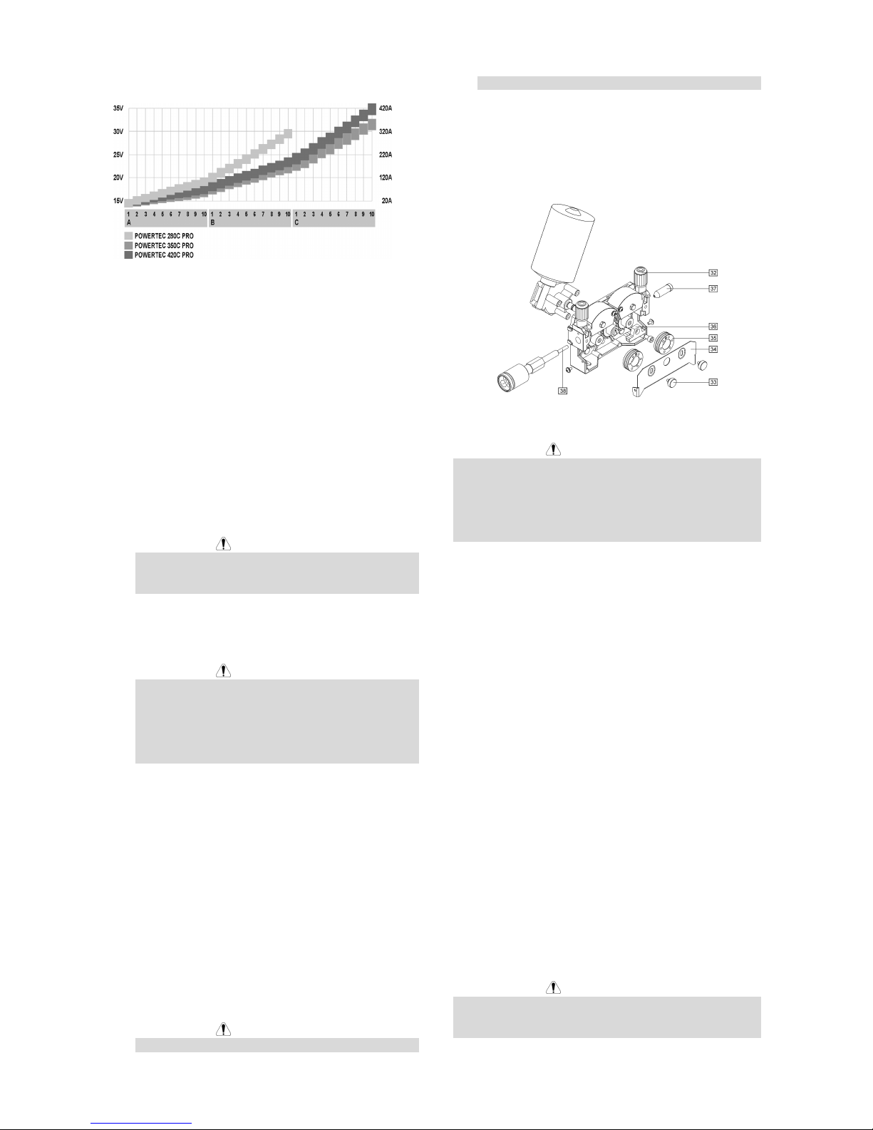
G-6
schema kan behulpzaam zijn bij de instelling:
• Rekening houdend met de bijbehorende regels, kan
men beginnen te lassen.
MIG / MAG lassen in de Synergische
(automatische) modus
Om te lassen in de synergische modus moet men:
• De netstekker in de stekkerdoos steken.
• Schakel de machine in met de Aan/Uit schakelaar
[1]. (de lamp moet branden).
• Voer de lasdraad in de toorts in met behulp van de
schakelaar “koude draadaanvoer” [5].
• Controleer de gasstroom met behulp van de
schakelaar “gas spoelen” [5].
• Stel de keuzeknop draaddiameter [16]
overeenkomend met de gebruikte draaddiameter.
• Stel de keuzeknop lasmateriaal en gassoort [17]
overeenkomend met het gebruikte lasmateriaal.
WAARSCHUWING
Indien de geselecteerde lasprocedure geen
synergisch process heeft, verschijnen er 3
horizontale streepjes op display “A”.
• Stel de juiste lasspanning in met de
keuzeschakelaars [3] afhankelijk van de gekozen
lasmethode en materiaaldikte.
WAARSCHUWING
In synergische lasmode kiest de machine
automatisch de juiste draadsnelheid bij elke positie
van de Spannings Keuzeschakelaars [3]. De
automatisch ingestelde snelheid kan bijgeregeld
worden ±25% met behulp van de knop
draadaanvoersnelheid [7].
• Rekening houdend met de bijbehorende regels, kan
men beginnen te lassen.
Draadaanvoerrollen wisselen
De machine wordt standaard vanaf de fabriek geleverd
met draadaanvoerrollen voor 1.0 en 1.2mm. Voor
andere draadiameters en draadsoorten zijn sets met
aangepaste draadaanvoerrollen beschikbaar. Hieronder
de werkwijze voor het wisselen van de
draadaanvoerrollen:
• Schakel de machine uit.
• Zet de drukrolbrug vrij [32].
• Verwijder de borgschroeven [33].
• Open de beschermkap [34].
• Wissel de draadaanvoerrollen [35] met de rollen
behorend bij de gebruikte draad.
WAARSCHUWING
Voor draden dikker dan 1.6mm, moeten ook
onderstaande onderdelen verwisselt worden:
• De draadinvoernippel en draaddoorvoernippel
[36] en [37].
• De geleidebuis in de Euroconnector [38].
• Plaats en bevestig de beschermkap [34] voor de
draadaanvoerrollen.
• Plaats de borgmoeren [33].
Onderhoud
WAARSCHUWING
Neem voor reparatie of onderhoud contact op met de
dichtstbijzijnde Lincoln Electric dealer of Lincoln Electric
service center zelf. Ondeskundig onderhoud en of
reparatie uitgevoerd door niet bevoegde personen
kunnen gevaarlijk zijn en zorgt ervoor dat de garantie
vervalt.
De onderhoudsinterval kan variëren en is afhankelijk van
meerdere factoren in de werkomgeving waarin deze
machine geplaatst is.
Elke waarneembare schade moet onmiddellijk gemeld
worden.
Dagelijks onderhoud
• Controleer de staat van kabels en connectors en
vervang of repareer deze indien nodig.
• Verwijder lasspatten uit de gascup van het
laspistool. Lasspatten kunnen de gasstroom van
het beschermgas beïnvloeden.
• Controleer de staat van het laspistool en vervang
deze indien nodig.
• Controleer de werking van de koelventilator van de
machine. Zorg ervoor dat de ventilatieopeningen
van de machine schoon zijn en er voldoende ruimte
is voor een vrije luchtstroom.
Periodiek onderhoud (elke 200 werkuren maar
niet minder dan 1 keer per jaar)
Voer het dagelijks onderhoud uit, voer daarnaast de
volgende werkzaamheden uit:
• Maak de machine schoon. Blaas de buitenkant en
de binnenkant schoon met schone, droge perslucht
(met een lage druk).
• Controleer alle schroeven en draai deze indien
nodig vast.
WAARSCHUWING
De Primaire netvoeding moet voor elek onderhoud of
servicebeurt uitgeschakeld worden. Controleer de
Veiligheid van de machine na iedere reparatie.
Page 59

Elektromagnetische Compatibiliteit (EMC)
11/04
Deze machine is ontworpen in overeenstemming met alle van toepassing zijnde bepalingen en normen. Desondanks
kan de machine elektromagnetische ruis genereren die invloed kan hebben op andere systemen zoals
telecommunicatiesystemen (radio, televisie en telefoon) of beveiligingssystemen. Deze storing of interferentie kan leiden
tot veiligheidsproblemen in het betreffende systeem. Lees en begrijp deze paragraaf om elektromagnetische
interferentie (storing), opgewekt door deze machine, te elimineren of te beperken.
Deze installatie is ontworpen om in een industriële omgeving gebruikt te worden. Het is belangrijk om voor
gebruik in een huiselijke omgeving aanvullende voorzorgsmaatregelen te nemen om mogelijke
elektromagnetische interferentie te elimineren. De gebruiker dient deze machine te installeren en te
gebruiken zoals beschreven in deze gebruiksaanwijzing. Indien elektromagnetische interferentie voorkomt,
dient de gebruiker maatregelen te nemen om deze interferentie te elimineren. Indien nodig kan hij hiervoor assistentie
vragen aan de dichtstbijzijnde Lincoln Electric vestiging.
Voordat de machine geïnstalleerd wordt dient de gebruiker de werkplek te controleren op apparatuur die t.g.v.
interferentie slecht functioneren. Let hierbij op:
• Primaire- en secundaire kabels, stuurstroomkabels en telefoonkabels in de directe en nabije omgeving van de
werkplek en de machine.
• Radio en/of televisie zenders en ontvangers. Computers of computergestuurde apparatuur.
• Beveiligen en besturingen van industriële processen. Meet en ijkgereedschap.
• Persoonlijke medische apparatuur zoals pacemakers en gehoorapparaten.
• Controleer de elektromagnetische immuniteit van apparatuur op of nabij de werkplek. De gebruiker dient er zeker
van te zijn dat alle apparatuur in de omgeving immuun is. Dit kan betekenen dat er aanvullende maatregelen
genomen moeten worden.
• De dimensies van het gebied waarvoor dit geldt hangen af van de constructie en andere activiteiten die
plaatsvinden.
Neem de volgende richtlijnen in acht om elektromagnetische emissie van de machine te beperken.
• Sluit de machine op het net aan zoals beschreven in deze gebruiksaanwijzing. Indien storing optreedt, kan het
nodig zijn aanvullende maatregelen te nemen zoals bijvoorbeeld het filteren van de primaire spanning.
• Las en werkstukkabels dienen zo kort mogelijk naast elkaar te liggen. Leg, indien mogelijk, het werkstuk aan aarde
om elektromagnetische emissie te beperken. De gebruiker moet controleren of het aan aarde leggen van het
werkstuk gevolgen heeft voor het functioneren van apparatuur en de veiligheid van personen.
• Het afschermen van kabels in het werkgebied kan elektromagnetische emissie beperken. Dit kan bij speciale
toepassingen nodig zijn.
Page 60

G-8
Technische Specificaties
POWERTEC 280C, 350C & 420C PRO:
PRIMAIR
Nominaal primair vermogen
280C PRO:
12 kVA @ 40% ID
350C PRO:
16 kVA @ 40% ID
Primaire spanning
230 / 400V ± 10%
Drie fase
420C PRO:
21 kVA @ 40% ID
Frequentie
50 Hertz (Hz)
NOMINAAL SECUNDAIR VERMOGEN BIJ 40°C
Inschakelduur
(op basis van een10 min. Cyclus)
Lasstroom secundair Lasspanning
280C PRO:
40%
60%
100%
280A
230A
175A
28.0 Vdc
25.5 Vdc
22.8 Vdc
350C PRO:
40%
60%
100%
350A
285A
220A
31.5 Vdc
28.2 Vdc
25.0 Vdc
420C PRO:
40%
60%
100%
420A
345A
265A
35.0 Vdc
31.3 Vdc
27.3 Vdc
SECUNDAIR BEREIK
Bereik lasstroom Maximum Open spanning
280C PRO:
30A - 280A
280C PRO:
39 Vdc
350C PRO:
30A - 350A
350C PRO:
42 Vdc
420C PRO:
30A - 420A
420C PRO:
49 Vdc
AANBEVOLEN PRIMAIRE KABEL EN ZEKERINGEN
Primairezekering of zekeringautomaat Primaire kabel
280C PRO:
230V circuit: 32A traag
400V circuit: 20A traag
280C PRO:
4 aderig, 4mm
2
350C PRO:
230V circuit: 40A traag
400V circuit: 25A traag
350C PRO:
4 aderig, 4mm
2
420C PRO:
230V circuit: 63A traag
400V circuit: 32A traag
420C PRO:
4 aderig, 6mm
2
AFMETINGEN EN GEWICHT
Gewicht
280C PRO:
142 kg
350C PRO:
147 kg
420C PRO:
157 kg
Hoogte
910 mm
Breedte
565 mm
700 mm
(water versie)
Lengte
1030 mm
420C PRO:
(water)
183 kg
Werktemperatuur
-10°C tot +40°C
Opslagtemperatuur
-25°C tot +55°C
Page 61
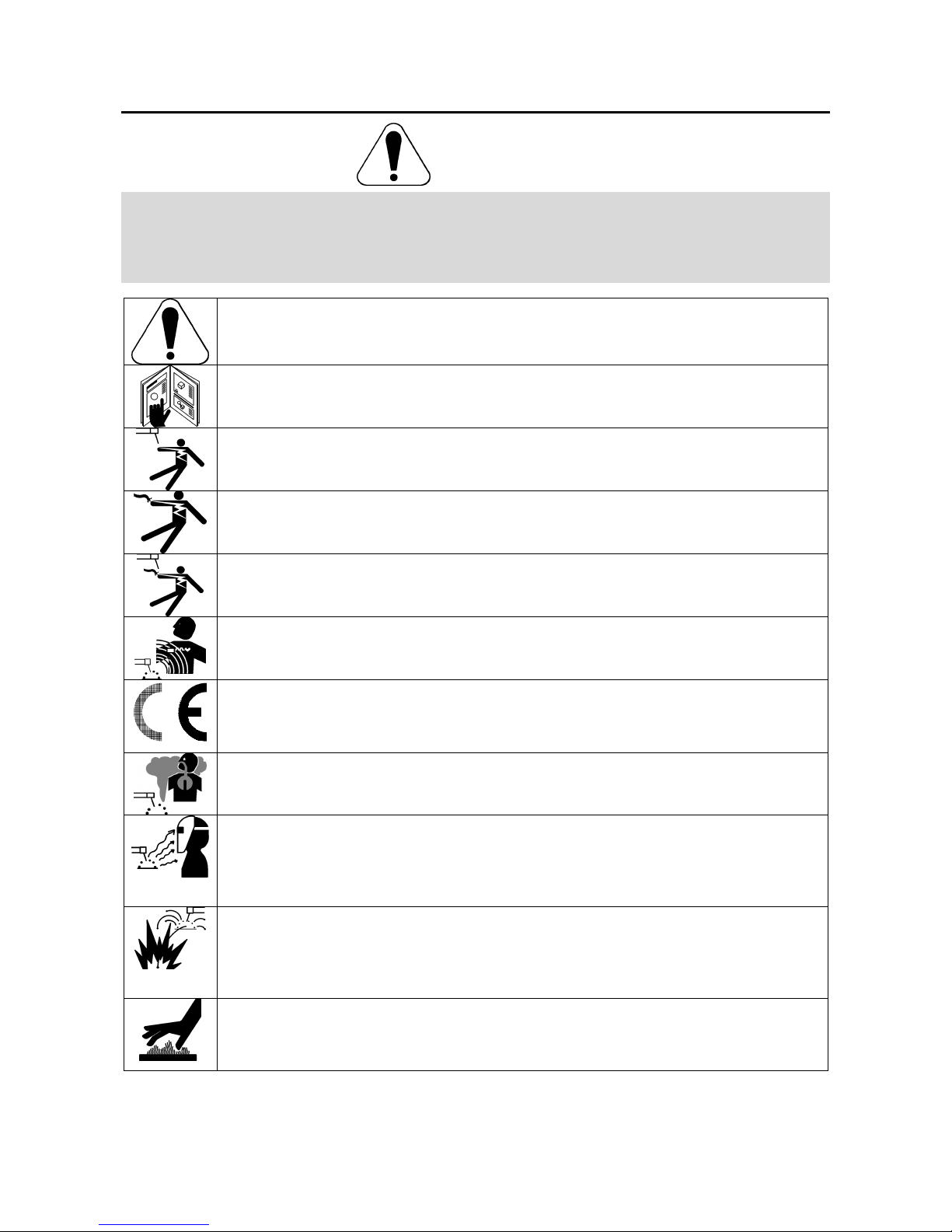
H-1
Säkerhetsanvisningar
11/04
VARNING
Denna utrusning får endast användas av behörig personal. Var noga med att enbart låta behörig personal utföra
installation, drift, underhåll och reparationer. Läs igenom bruksanvisningen för full förståelse innan utrustningen tas i
drift. Underlåtenhet att följa instruktionerna i bruksanvisningen kan medföra allvarliga personskador, förlust av liv eller
skador på utrustningen. Det är viktigt att läsa, och förstå, förklaringarna nedan till varningssymbolerna. Lincoln Electric
ikläder sig inget ansvar för skador som är orsakade av felaktig installation, eftersatt underhåll eller onormala
driftförhållanden.
VARNING: Symbolen innebär att instruktionerna måste följas för att allvarliga personskador, förlust
av liv eller skador på utrustningen skall kunna undvikas. Skydda Er själv och andra mot allvarliga
skador eller dödsfall.
LÄS OCH FÖRSTÅ INSTRUKTIONERNA: Läs igenom, och förstå, den här bruksavisningen innan
utrustningen tas i drift. Ljusbågsvetsning kan vara farligt. Underlåtenhet att följa instruktionerna i
bruksanvisningen kan medföra allvarliga personskador, förlust av liv eller skador på utrustningen.
ELEKTRISK STÖT KAN DÖDA: En svetsutrustning skapar höga spänningar. Rör därför aldrig vid
elektroden, jordklämman eller anslutna arbetsstycken när utrustningen är aktiv. Isolera Er från
elektroden, jordklämman och anslutna arbetsstycken.
ELEKTRISK UTRUSTNING: Stäng av matningsspänningen med hjälp av strömställaren på
säkringsboxen innan något arbete utförs på utrustningen. Jorda utrustningen i enlighet med lokala
elektriska föreskrifter.
ELEKTRISK UTRUSTNING: Kontrollera regelbundet spänningsmatningen och kablarna till elektroden
och jordklämman. Byt omedelbart ut kablar med skadad isolering. För att undvika att det oavsiktligt
uppstår en ljusbåge får man aldrig placera elektrodhållaren direkt på svetsbordet eller på någon
annan yta som är i kontakt med jordklämman.
ELEKTRISKA OCH MAGNETISKA FÄLT KAN VARA FARLIGA: En elektrisk ström som flyter genom
en ledare ger upphov till elektriska och magnetiska fält. Dessa kan störa vissa pacemakers och
svetsare som har pacemaker måste konsultera sin läkare innan de använder den här utrustningen.
CE - MÄRKNING: Denna utrustning är tillverkad i enlighet med relevanta EU direktiv.
ÅNGOR OCH GASER KAN VARA FARLIGA: Vid svetsning kan det bildas hälsovådliga ångor och
gaser. Undvik att andas in dessa ångor och gaser. För att undvika dessa risker måste operatören ha
tillgång till tillräcklig ventilation eller utsug för att hålla ångorna och gaserna borta från andningszonen.
STRÅLNING FRÅN LJUSBÅGEN KAN GE BRÄNNSKADOR: Använd en skärm eller svetshjälm med
ett, för uppgiften, lämpligt filter för att skydda ögonen mot sprut och strålning från ljusbågen under
svetsningen och när ljusbågen betraktas. Använd en lämplig klädsel av flamskyddat material för att
skydda Din och Dina medhjälpares hud. Skydda personal i närheten med en lämplig skärm av icke
brännbart material och varna dem så att de inte tittar på ljusbågen eller exponerar sig för ljusbågens
strålning.
SVETSSPRUT KAN ORSAKA BRÄNDER ELLER EXPLOSION: Avlägsna brännbara föremål från
svetsområdet och ha alltid en eldsläckare till hands. Svetssprut och heta partiklar från
svetsprocessen kan lätt passera genom små springor eller öppningar in till omkringliggande områden.
Svetsa aldrig på tankar, fat, containers eller andra föremål innan Du har förvissat Dig om att det inte
finns några brännbara eller giftiga ångor närvarande. Använd aldrig utrustningen i närheten av
brännbara gaser, ångor eller vätskor.
SVETSAT MATERIAL KAN ORSAKA BRÄNNSKADOR: Svetsning genererar mycket värme. Heta
ytor och material i arbetsområdet kan orsaka allvarliga brännskador. Använd handskar och en tång
för att flytta eller hantera material inom arbetsområdet.
Page 62

H-2
SÄKERHETSMÄRKNING: Denna utrustning är lämplig att använda för svetsning i en miljö där det
föreligger en förhöjd risk för elektrisk stöt.
GASFLASKOR KAN EXPLODERA OM DE ÄR SKADADE: Använd enbart föreskrivna gasflaskor
med en skyddsgas som är avpassad för den aktuella processen. Var noga med att enbart använda
en tryckregulator som är avsedd för den aktuella skyddsgasen och det aktuella trycket. Förvara alltid
gasflaskor stående upprätt och förankrade till ett fast föremål. Flytta eller transportera aldrig
gasflaskor utan att först montera skyddshatten. Låt aldrig elektroden, elektrodhållaren, jordklämman
eller någon annan del som är spänningssatt komma i kontakt med gasflaskan. Gasflaskor skall
förvaras på ett sådant sätt att de inte utsätts för fysisk åverkan eller för sprut och värmestrålning från
svetsprocessen.
Instruktioner för Installation och Handhavande
Läs hela detta avsnitt innan installation och användning
av utrustningen.
Placering och arbetsmiljö
Maskinen är konstruerad för att arbeta under besvärliga
förhållanden. Det är emellertid viktigt att vidta vissa
enkla försiktighetsåtgärder för att säkerställa lång
livslängd och tillförlitlig drift.
• Placera aldrig maskinen på en yta som lutar mer än
15° från horisontalplanet.
• Använd inte denna maskin för att tina frusna rör
genom kortslutning.
• Maskinen måste placeras så att den fria
strömningen av ren luft till och från
ventilationsöppningarna inte hindras. Täck aldrig
över maskinen med papper, trasor eller annat som
kan hindra luftströmningen.
• Smuts och damm måste förhindras att sugas in i
maskinen så långt det ät möjligt.
• Maskinen håller skyddsklass IP23. Håll maskinen
torr så långt det är praktiskt möjligt. Placera den
inte på våt mark eller i vattenpölar.
• Placera inte maskinen i närheten av radiostyrd
utrustning. Även vid normal användning kan
funktionen hos radiostyrd utrustning störas allvarligt
vilket kan leda till olyckor eller skada på
utrustningen. Läs avsnittet om elektromagnetisk
kompabilitet i denna manual.
• Använd inte maskinen om omgivningstemperaturen
överstiger 40°C.
Intermittens och överhettning
En svetsmaskins intermittens är andelen tid i procent av
ett tiominutersintervall som svetsaren kan använda
svetsmaskinen vid märkström.
Exempel: 60% intermittens:
6 minuters belastning. 4 minuters uppehåll.
Överskridning av imtermittenstiden aktiverar
överhettningsskyddet.
Svetsningstransformatorn i maskinen skyddas mot
överhettning av en termostat. När maskinen överhettas
bryts svetsströmmen och överhettningslampan tänds.
När maskinen svalnat till en säker temperatur släcks
överhettningslampan och maskinen kan användas igen.
OBS: Av säkerhetsskäl kan maskinen inte gå ur
överhettningsläget förrän avtryckaren på svetspistolen
släpps.
Minuter Eller minskad
belastning
Inkoppling av matningsspänning
Installation av nätkontakter ska göras i enlighet med
gällande regler.
Kontrollera matningsspänning, fas och frekvens
inkopplat till maskinen innan den sätts på. Kontrollera
att maskinen är korrekt jordad. Tillåten
matningsspänning är 3x230V och 3x400V (förvald
inställning: 400V). För ytterligare information om
matningsspänning se avsnittet om tekniska
specifikationer i denna manual samt märkplåten på
maskinen.
Om matningsspänningen behöver ändras:
• Kontrollera att maskinen är avstängd och
frånkopplad från strömkällan.
• Ta bort sidskyddet från maskinen.
• Koppla X11 och X12 enligt bilden nedan.
X12
400V
X11
X12
230V
X11
• Sätt tillbaka sidoskyddet.
Kontrollera att den installerade effekten är tillräcklig i
förhållande till maskinens normala drift. Nödvändiga
säkringar och kabelareor finns angivna i avsnittet om
Tekniska data.
Se punkterna [1] och [20] i bilderna nedan.
Anslutningar för svetsström
Se punkterna [8], [10] och [11] i bilderna nedan.
Reglage, anslutningar och funktioner
Page 63
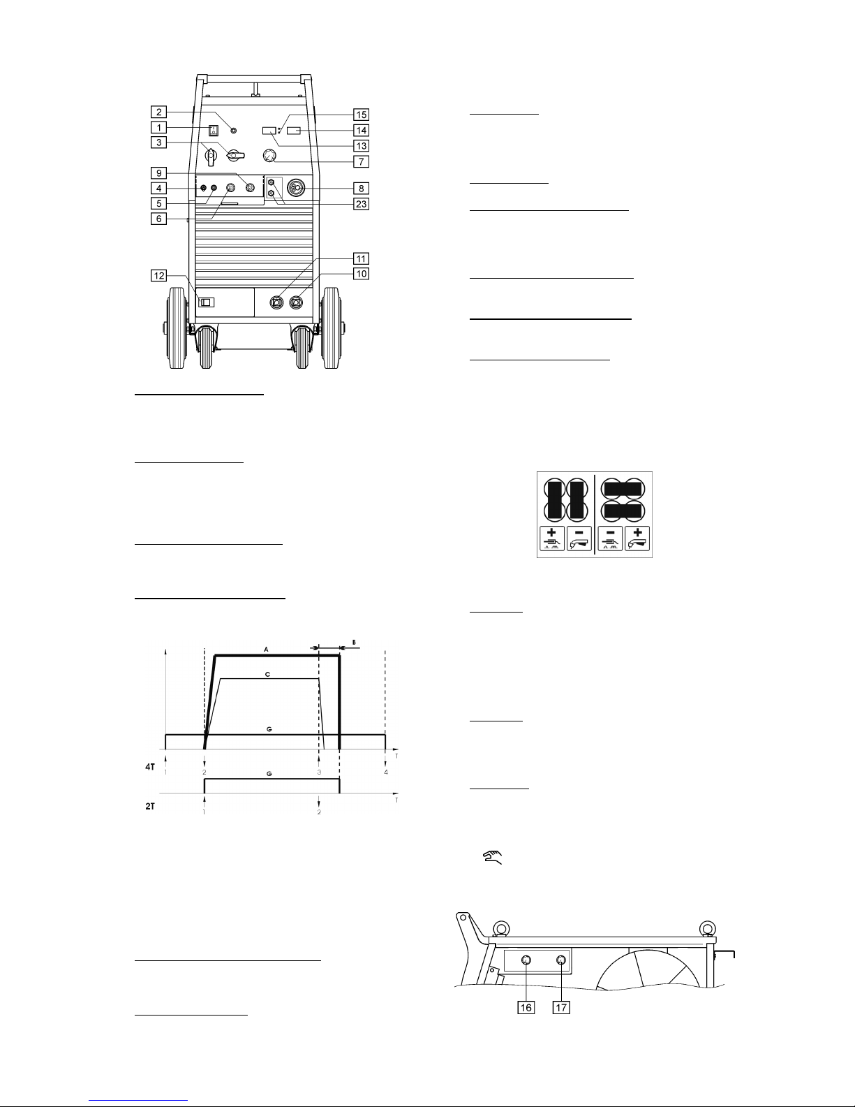
H-3
1. Strömbrytare och lampa: När matningsspänningen
är inkopplad och maskinen sätts på med
strömbrytaren lyser lampan och svetsmaskinen är
klar att användas.
2. Överhettningslampa: Denna lampa lyser när
överhettningsskyddet är aktiverat och
svettströmmen automatiskt avstängt. Låt maskinen
svalna, när lampan slocknar är maskinen klar att
användas igen.
3. Svetsspänningsomkopplare: POWERTEC 280C
har 2 omkopplare (2 och 10 steg). POWERTEC
350C och 420C har 2 omkopplare (3 och 10 steg).
4. Brytare för avtryckarfunktion: Möjliggör val av 2takts eller 4-takts avtryckarunktion. Beskrivning av
2-takt och 4-takt i bilden nedan:
↑
Avtryckaren intryckt
↓
Avtryckaren uppsläppt
A. Svetsström.
B. Burnback tid.
C. Trådmatning.
G. Gas.
5. Kallmatning / Gasströmningsknapp: Denna knapp
möjliggör trådmatning eller gasströmning utan att
svetsspänningen behöver aktiveras.
6. Trådmatning, Lågfart: Möjliggör inställning av
trådmatningshastigheten innan ljusbågen tänds, i
området 0.5 till1.0 av inställd trådmatning på ratt [7].
7. Trådmatning: Möjliggör kontinuerlig inställning av
trådmatningshastigheten från 1.0 till 20m/min vid
manuell svetsning eller justering av den förvalda
trådmatningen ±25% i synergiskt läge.
8. EURO-kontakt: För inkoppling av svetspistol.
9. Kontrollratt för trådavbränning: Möjliggör inställning
av längden på svetstråden som sticker ut från
svetspistolen efter avslutad svetsning. Justerbra tid
mellan 8 och 250ms.
10. Anslutning med Hög Induktans: För anslutning av
återledarkaben.
11. Anslutning med Låg Induktans: För anslutning av
återledarkaben.
12. Kopplingsplint för Polaritet: Möjliggör att välja
polaritet (+/-) för svetspistolen. (Fabriksinställning:
“+” på svetspistolen).
Vid polaritetsändring:
• Stäng av maskinen och koppla den från elnätet.
• Lossa locket över kopplingsplinten.
• Placera kopplingsblecken enligt bilden nedan.
• Sätt tillbaka locket.
13. Display A: Visar verklig svetsström (i A) och efter
avslutad svetsning visas den genomsnittliga
svetsströmmen i 5s. Efter denna tid visas den
förinställda trådmatningshastigheten (i m/min) i
manuellt läge eller,justeringen av den förvalda
matningshastigheten i området 0.75-1.25 i
synergiskt läge.
14. Display V: Visar verklig svetsspänning (i V) och
efter avslutad svetsning visas den genomsnittliga
svetsspänningen i 5s. Efter denna tid är displayen
blank.
15. Arbetsläge: Dessa lampor anger maskinens
arbetsläge:
SYNERGIC
När denna är tänd arbetar maskinen i
Synergiskt (automatiskt) läge.
När denna är tänd arbetar maskinen i
Manuellt läge.
Välj önskat arbetsläge med ratt [17].
Page 64

H-4
16. Tråddiameter: Möjliggör inställning av tråddiameter
för den önskade svetsprocessen. Denna funktion
avänds endast i synergiskt läge.
17. Material och Gastyp: Möjliggör val av:
• Materialtyp och lämplig skyddsgas.
• Manuellt eller synergiskt läge.
18. Anslutning: För inkoppling av gasslang.
19. Bakom täcklocket: Anslutning för CO2 gasvärmare.
20. Nätkabel: Montera kontakt enligt gällande regler.
Endast kvalificerad personal ska montera denna
kontakt.
21. Uttag för vattenkylare (endast på vattenkylda
modeller): För strömförsörjning av vattenkylare,
230V, 2.5A automatsäkring [22]. Se punkt [24] för
ytterligare detaljer.
22. Automatsäkring (endast på vattenkylda modeller):
Skyddar uttaget för vattenkylare [21]. Bryter
strömmen om den överstiger 2.5A. Tryck för att
återställa.
23. Snabbkopplingar (endast för vattenkylda modeller):
För anslutning av slangarna från vattenkylaren [24].
Svetspistolens vattenslangar ansluts till
motsvarande snabbkopplingar på maskinens
framsida.
24. Vattenkylare (endast för vattenkylda modeller):
Kyler den vattenkylda svetspistolen. Kylaren styrs
automatiskt enligt följande:
• När svetsningen påbörjas startar kylaren
automatiskt.
• När svetsningen avslutas fortsätter kylaren att
gå i ca 5min innan den automatiskt stängs av.
• Om svetsningen återupptas inom dessa 5min
fortsätter kylaren att gå.
VARNING
Läs och förstå kylarens manual innan den ansluts till
maskinen.
Kopplingar för svetskablar
Anslut återledarkabeln till [10] eller [11].
Återledarkabelns godsklämma ansluts till arbetsstycket.
Anslut en svetspistol utrustad för det aktuella svetsjobbet
till EURO-kontakten.
Laddning av svetstråd
Öppna maskinens sidolucka.
Lossa muttern från bobinaxeln.
Sätt trådbobinen på axeln så att den roterar medurs när
tråden matas in i matarverket.
Se till att axelns styrstift går in i motsvarande hål i
bobinen.
Dra åt muttern på bobinaxeln.
Använd matarhjul med spår som överensstämmer med
den använda trådtypen och -diametern.
Lossa trådändan från bobinen, klipp av den böjda ändan
och se till att den är fri från grader.
VARNING
Trådändan kan vara vass.
Rotera bobinen medurs och trä tråden genom
matarverket.
Fäll ner tryckrullarna och ställ in trycket på dessa.
25. Axel.
Page 65

H-5
26. Trådspole.
27. Svetstråd.
28. Matarverk.
Maskinen är byggd för att klara 15kg (300mm) trådspole.
Justering av axelns bromsverkan
För att undvika att svetstråden rullas ut av sig självt är
axeln utrustad med en broms.
Justering av bromsverkan görs med justerskruven
bakom axelns muttern.
29. Mutter.
30. Justerskruv.
31. Tryckfjäder.
Skruvas justerskruven medurs ökas fjädertrycket och
därmed ökas bromsmomentet.
Skruvas justerskruven moturs minskas fjädertrycket och
därmed minskas bromsmomentet.
Efter justeringen skruvas muttern på igen.
Justering av tryckrullarnas tryck
Tryckrullens tryck ökas mot svetstråden genom att
justemuttern skruvas medurs och trycket minskas
genom att skruva moturs.
VARNING
Om tryckrullens tryck är för lågt kommer matarhjulet slira
mot svetstråden. Om trycket är för högt kommer
svetstråden deformeras vilket leder till matningsproblem
i svetspistolen. För att ställa in rätt tryck gör följande:
Minska trycket långsamt tills matarhjulet börjar slira på
svetstråden, öka sedan trycket lite genom att vrida
muttern ett varv.
Matning av svetstråden i svetspistolen
Anslut en lämplig svetspistol till Euro-kontakten,
svetspistolens prestanda skall motsvara
svetsmaskinens.
Slå till nätspänningen (nätbrytaren [1] i läge “I”).
Lossa gaskåpa och kontaktmunstycke från
svetspistolen.
Ställ in trådmatningshastigheten på ca 10m/min med ratt
[7].
Tryck brytare [5] i läget “Cold Inch” och håll den så tills
trden matats genom svetspistolen.
VARNING
Var försiktig och håll ögon och händer borta från änden
på svetspistolen under trådmatning.
VARNING
När tråden matats till rätt läge, stäng av maskinen helt
innan gaskåpan och kontaktmunstycket sätts tillbaka på
svetspistolen.
Gastillförsel
Sätt in gasslangen i anslutningen på baksidan av
svetsmaskinen.
Sätt gasflaskan på maskinens gasflaskehylla och säkra
den med kedjan.
Tag bort säkerhetskåpan från gasflaskan och sätt
flödesregulatorn därpå.
Montera gasslangen på flödesregulatorn med
slangklämman.
MIG/MAG-svetsning i manuellt läge
För att MIG/MAG-svetsa i manuellt läge ska du:
• Koppla maskinen till nätet.
• Slå till nätspänningen (nätbrytaren [1] i läge “I”).
(Den ska tändas).
• Mata fram tråden genom svetspistolen med brytare
[5].
• Kontrollera gasflödet med brytare [5].
• Ställ in ratt [17] i manuellt läge (se så att lampa [15]
indikerar manuellt läge).
• Beroende på godstjocklek och tråddiameter ställs
lämplig svetsspänning in med omkopplarna [3] och
trådmatningshastiget med ratt [7]. Tabellen nedan
kan vara användbar vid inställning:
• Om ovan följda punkter är uppfyllda kan
svetsningen påbörjas.
MIG/MAG-svetsning i synergiskt
(automatiskt) läge
För att MIG/MAG-svetsa i manuellt läge ska du:
• Koppla maskinen till nätet.
• Slå till nätspänningen (nätbrytaren [1] i läge “I”).
(Den ska tändas).
• Mata fram tråden genom svetspistolen med brytare
[5].
• Kontrollera gasflödet med brytare [5].
• Ställ in ratt [16] på tråddiameter som används.
• Ställ in ratt [17] på det material som ska svetsas.
VARNING
Om den valda svetsprocessen inte har någon
synergikurva kommer tre horisontella streck att
visas i display “A”.
• Ställ in lämplig svetsspänning till den aktuella
Page 66

H-6
godstjockleken och tråden med omkopplarna [3].
VARNING
I synergiskt läge ställs automatiskt in en lämplig
trådmatningshastighet i förhållande till inställd
svetsspänning på omkopplarna [3].
Trådmatningshastigheten kan justeras ±25% med
ratt [7].
• Om ovan följda punkter är uppfyllda kan
svetsningen påbörjas.
Byte av drivhjul
Maskinen är fabriksutrustad med drivhjul för 1.0 och
1.2mm homogentråd. Drivhjul för andra trådtyper och –
dimensioner finns som tillbehör. Se instruktionerna
nedan för att byta drivhjul:
• Stäng av maskinen.
• Lossa tryckarmarna [32].
• Ta loss låsskruvarna [33].
• Ta bort skyddsplåten [34].
• Byt drivhjulen [35] till rätt typ för den aktuella tråden.
VARNING
För trådar grövre än 1.6mm måste även följande
delar bytas:
• Guiderören i matarverkschassiet [36] och [37].
• Guideröret i Euro-kopplingen [38].
• Sätt tillbaka skyddsplåten [34] över drivhjulen.
• Skruva fast skyddet med låsskruvarna [33].
Underhåll
VARNING
Kontakta närmaste auktoriserade verkstad, eller Lincoln
Electric, för åtgärder när det gäller service och underhåll
eller reparationer. Underhåll och reparationer som
genomförs av icke auktoriserade verkstäder eller
personer upphäver tillverkarens garantiåtagande och gör
detta ogiltigt.
Underhållsintervallen varierar med maskinens
arbetsförhållanden.
Synliga skador ska åtgärdas omedelbart.
Rutinmässigt underhåll (dagligen)
• Kontrollera kablarnas och anslutningarnas skick.
Byt ut om nödvändigt.
• Avlägsna svetssprut ur svetspistolen. Svetssprut
kan störa gasflödet genom svetspistolen.
• Kontrollera svetspistolens skick. Byt ut den om
nödvändigt.
• Kontrollera att kylfläkten fungerar. Håll
ventilationsgallren rena.
Periodiskt underhåll (efter 200 arbetstimmar,
dock minst en gång per år)
Gör det rutinmässiga underhållet, samt:
• Rengör maskinen. Lossa plåtarna och använd
tryckluft (torr luft med lågt tryck) för att avlägsna
damm från maskinens utsida och insida.
• Kontrollera och dra åt alla skruvar.
VARNING
Koppla loss maskinen från elnätet före underhåll och
service. Testa maskinen efter reparation för att
säkerställa en säker funktion.
Page 67

H-7
Elektromagnetisk Kompatibilitet (EMC)
11/04
Den här maskinen är tillverkad i enlighet med alla relevanta direktiv och standarder. Trots detta kan den ge upphov till
elektromagnetiska störningar som kan påverka andra system, som t.ex. telekommunikationer (telefon, radio och
television) eller andra säkerhetssystem. Dessa störningar kan ge upphov till säkerhetsproblem i de påverkade
systemen. Läs det här avsnittet för att få en bättre kunskap om hur man eliminerar eller minskar de elektromagnetiska
störningar som maskinen ger upphov till.
Maskinen är konstruerad för att användas i industriell miljö. Om den skall användas i hemmiljö är det
nödvändigt att vidta särskilda försiktighetsåtgärder för att undanröja de elektromagnetsiska störningar som
kan tänkas uppträda. Utrustningen måste installeras och manövreras på det sätt som beskrivs i den här
bruksanvisningen. Om elektromagnetiska störningar upptäcks under drift måste man vidta lämpliga
åtgärder för att eliminera dessa. Om det är nödvändigt kan detta ske med hjälp från Lincoln Electric. Det är inte tillåtet
att genomföra förändringar eller modifieringar på maskinen utan skriftligt tillstånd från Lincoln Electric.
Innan maskinen installeras måste man kontrollera arbetsområdet så att där inte finns några maskiner, apparater eller
annan utrustning vars funktion kan störas av elektromagnetiska störningar. Beakta särskilt följande:
• Nätkablar, svetskablar, manöverkablar och telefonkablar som befinner sig inom eller i närheten av maskinens
arbetsområde.
• Radio och/eller televisionssändare eller mottagare. Datorer och datorstyrd utrustning.
• Säkerhets- och övervakningssystem för industriella processer. Utrustning för mätning och kalibrering.
• Medicinska hjälpmedel för personligt bruk som t.ex. pacemaker och hörapparater.
• Kontrollera den elektromagnetiska störkänsligheten för utrustning som skall arbeta i arbetsområdet eller i dess
närhet. Operatören måste förvissa sig om att all utrustning inom området är kompatibel i detta avseende vilket kan
kräva ytterligare skyddsåtgärder.
• Arbetsområdets storlek är beroende av områdets utformning och de övriga aktiviteter som kan förekomma där.
Beakta följande riktlinjer för att reducera maskinens elektromagnetiska strålning.
• Koppla in maskinen till spänningsförsörjningen enligt anvisningarna i den här bruksanvisningen. Om störningar
uppstår kan det bli nödvändigt att installera ett filter på primärsidan.
• Svetskablarna skall hållas så korta som möjligt och de skall placeras intill varandra. Jorda arbetsstycket, om det är
möjligt, för att på så sätt minska den elektromagnetiska strålningen. Man måste emellertid kontrollera att jordningen
inte medför andra problem eller medför risker för utrustning och personal.
• Att använda skärmade kablar inom arbetsområdet kan reducera den elektromagnetiska strålningen. Detta kan bli
nödvändigt för vissa speciella tillämpningar.
Page 68

H-8
Tekniska Specifikationer
POWERTEC 280C, 350C & 420C PRO:
NÄTSIDA
Effektförbrukning
280C PRO:
12 kVA @ 40% Intermittens
350C PRO:
16 kVA @ 40% Intermittens
Nätspänning
230 / 400V ± 10%
3-fas
420C PRO:
21 kVA @ 40% Intermittens
Frekvens
50 Hertz (Hz)
SVETSDATA VID 40°C
Intermittens
(Baserat på 10 min. period)
Svetsström Svetsspänning
280C PRO:
40%
60%
100%
280A
230A
175A
28.0 Vdc
25.5 Vdc
22.8 Vdc
350C PRO:
40%
60%
100%
350A
285A
220A
31.5 Vdc
28.2 Vdc
25.0 Vdc
420C PRO:
40%
60%
100%
420A
345A
265A
35.0 Vdc
31.3 Vdc
27.3 Vdc
SVETSOMRÅDE
Svetsströmsområde Max. tomgångsspänning
280C PRO:
30A - 280A
280C PRO:
39 Vdc
350C PRO:
30A - 350A
350C PRO:
42 Vdc
420C PRO:
30A - 420A
420C PRO:
49 Vdc
REKOMMENDERADE NÄTKABLAR OCH SÄKRINGAR
Smält- eller automatsäkring Nätkabel
280C PRO:
32A Trög (230V)
20A Trög (400V)
280C PRO:
4 x 4mm
2
350C PRO:
40A Trög (230V)
25A Trög (400V)
350C PRO:
4 x 4mm
2
420C PRO:
63A Trög (230V)
32A Trög (400V)
420C PRO:
4 x 4mm
2
MÅTT OCH VIKT
Vikt
280C PRO:
142 kg
350C PRO:
147 kg
420C PRO:
157 kg
Höjd
910 mm
Bredd
565 mm
700 mm
(vattenkyld)
Längd
1030 mm
420C PRO:
(vattenkyld)
183 kg
Omgivningstemp. vid användning
-10°C till +40°C
Förvaringstemperatur
-25°C till +55°C
Page 69

I-1
Bezpieczeństwo Użytkowania
11/04
OSTRZEŻENIE
Urządzenie to może być używane tylko przez wykwalifikowany personel. Należy być pewnym, że instalacja, obsługa,
przeglądy i naprawy są przeprowadzane tylko przez osoby wykwalifikowane. Instalacji i eksploatacji tego urządzenia
można dokonać tylko po dokładnym zapoznaniu się z tą instrukcją obsługi. Nieprzestrzeganie zaleceń zawartych w tej
instrukcji może narazić użytkownika na poważne obrażenie ciała, śmierć lub uszkodzenie samego urządzenia. Lincoln
Electric nie ponosi odpowiedzialności za uszkodzenia spowodowane niewłaściwą instalacją, niewłaściwą konserwacją
lub nienormalną obsługą.
OSTRZEŻENIE: Symbol ten wskazuje, że bezwzględnie muszą być przestrzegane instrukcje dla
uniknięcia poważnego obrażenia ciała, śmierci lub uszkodzenia samego urządzenia. Chroń siebie i
innych przed możliwym poważnym obrażeniem ciała lub śmiercią.
CZYTAJ ZE ZROZUMIENIEM INSTRUKCJĘ: Przed rozpoczęciem użytkowania tego urządzenia
przeczytaj niniejszą instrukcję ze zrozumieniem. Łuk spawalniczy może być niebezpieczny.
Nieprzestrzeganie instrukcji tutaj zawartych może spowodować poważne obrażenia ciała, śmierć lub
uszkodzenie samego urządzenia.
PORAŻENIE ELEKTRYCZNE MOŻE ZABIĆ: Urządzenie spawalnicze wytwarza wysokie napięcie.
Nie dotykać elektrody, uchwytu spawalniczego lub podłączonego materiału spawanego, gdy
urządzenie jest załączone do sieci. Odizolować siebie od elektrody, uchwytu spawalniczego i
podłączonego materiału spawanego.
URZĄDZENIE ZASILANE ELEKTRYCZNIE: Przed przystąpieniem do jakichkolwiek prac przy tym
urządzeniu odłączyć jego zasilanie sieciowe. Urządzenie to powinno być zainstalowane i uziemione
zgodnie z zaleceniami producenta i obowiązującymi przepisami.
URZĄDZENIE ZASILANE ELEKTRYCZNIE: Regularnie sprawdzać kable zasilający i spawalnicze z
uchwytem spawalniczym i zaciskiem uziemiającym. Jeżeli zostanie zauważone jakiekolwiek
uszkodzenie izolacji, natychmiast wymienić kabel. Dla uniknięcia ryzyka przypadkowego zapłonu nie
kłaść uchwytu spawalniczego bezpośrednio na stół spawalniczy lub na inną powierzchnię mającą
kontakt z zaciskiem uziemiającym.
POLE ELEKTROMAGNETYCZNE MOŻE BYĆ NIEBEZPIECZNE: Prąd elektryczny płynący przez
jakikolwiek przewodnik wytwarza wokół niego pole elektromagnetyczne. Pole elektromagnetyczne
może zakłócać pracę rozruszników serca i spawacze z wszczepionym rozrusznikiem serca przed
podjęciem pracy z tym urządzeniem powinni skonsultować się ze swoim lekarzem.
ZGODNOŚĆ Z CE: Urządzenie to spełnia zalecenia Europejskiego Komitetu CE.
OPARY I GAZY MOGĄ BYĆ NIEBEZPIECZNE: W procesie spawania mogą powstawać opary i gazy
niebezpieczne dla zdrowia. Unikać wdychania tych oparów i gazów. Dla uniknięcia takiego ryzyka
musi być zastosowana odpowiednia wentylacja lub wyciąg usuwający opary i gazy ze strefy
oddychania.
PROMIENIE ŁUKU MOGĄ POPARZYĆ: Stosować maskę ochronną z odpowiednim filtrem i osłony
dla zabezpieczenia oczu przed promieniami łuku podczas spawania lub jego nadzoru. Dla ochrony
skóry stosować odpowiednią odzież wykonaną z wytrzymałego i niepalnego materiału. Chronić
personel postronny, znajdujący się w pobliżu, przy pomocy odpowiednich, niepalnych ekranów lub
ostrzegać ich przed patrzeniem na łuk lub wystawianiem się na jego oddziaływanie.
ISKRY MOGĄ SPOWODOWAĆ POŻAR LUB WYBUCH: Usuwać wszelkie zagrożenie pożarem z
obszaru prowadzenia prac spawalniczych. W pogotowiu powinny być odpowiednie środki gaśnicze.
Iskry i rozgrzany materiał pochodzące od procesu spawania łatwo przenikają przez małe szczeliny i
otwory do przyległego obszaru. Nie spawać żadnych pojemników, bębnów, zbiorników lub materiału
dopóki nie zostaną przedsięwzięte odpowiednie kroki zabezpieczające przed pojawieniem się
łatwopalnych lub toksycznych gazów. Nigdy nie używać tego urządzenia w obecności łatwopalnych
gazów, oparów lub łatwopalnych cieczy.
SPAWANY MATERIAŁ MOŻE POPARZYĆ: Proces spawania wytwarza dużą ilość ciepła.
Rozgrzane powierzchnie i materiał w polu pracy mogą spowodować poważne poparzenia. Stosować
rękawice i szczypce, gdy dotykamy lub przemieszczamy spawany materiał w polu pracy.
Page 70

I-2
ZNAK BEZPIECZEŃSTWA: Urządzenie to jest przystosowane do zasilania sieciowego, do prac spawalniczych prowadzonych w środowisku o podwyższonym ryzyku porażenia elektrycznego.
BUTLA MOŻE WYBUCHNĄĆ JEŚLI JEST USZKODZONA: Stosować tylko butle atestowane z
gazem odpowiedniego rodzaju do stosowanego procesu i poprawnie działającymi regulatorami
ciśnienia, przeznaczonymi dla stosowanego gazu i ciśnienia. Zawsze utrzymywać butlę w pionowym
położeniu, zabezpieczając ją łańcuchem przed wywróceniem się. Nie przemieszczać i nie
transportować butli z gazem ze zdjętym kołpakiem zabezpieczającym. Nigdy nie dotykać elektrody,
uchwytu spawalniczego, zacisku uziemiającego lub jakiegokolwiek elementu obwodu przewodzącego
prąd do butli z gazem. Butle z gazem muszą być umieszczane z dala od miejsca gdzie mogłyby ulec
uszkodzeniu lub gdzie byłyby narażone na działanie iskier lub rozgrzanej powierzchni.
Instrukcja Instalacji i Eksploatacji
Przed instalacją i rozpoczęciem użytkowania tego
urządzenia należy przeczytać cały ten rozdział.
Warunki Eksploatacji
Urządzenie to może pracować w ciężkich warunkach.
Jednakże ważnym jest zastosowanie prostych środków
zapobiegawczych, które zapewnią długą żywotność i
niezawodną pracę, między innymi:
• Nie umieszczać i nie użytkować tego urządzenia na
powierzchni o pochyłości większej niż 15°.
• Nie używać tego urządzenia do rozmrażania rur.
• Urządzenie to musi być umieszczone w miejscu
gdzie występuje swobodna cyrkulacja czystego
powietrza bez ograniczeń przepływu powietrza do i
od wentylatora. Gdy urządzenie jest załączone do
sieci, niczym go nie przykrywać np. papierem lub
ścierką.
• Ograniczyć do minimum brud i kurz, które mogą
przedostać się do urządzenia.
• Urządzenie to posiada stopień ochrony obudowy
IP23. Utrzymywać je suchym, o ile to możliwe, i nie
umieszczać na mokrym podłożu lub w kałuży.
• Urządzenie to powinno być umieszczone z dala od
urządzeń sterowanych drogą radiową. Jego
normalna praca może niekorzystnie wpłynąć na
ulokowane w pobliżu urządzenia sterowane
radiowo, co może doprowadzić do obrażenia ciała
lub uszkodzenia urządzenia. Przeczytaj rozdział o
kompatybilności elektromagnetycznej zawarty w tej
instrukcji.
• Nie używać tego urządzenia w temperaturach
otoczenia wyższych niż 40°C.
Cykl Pracy i Przegrzanie
Cykl pracy urządzenia jest procentowym podziałem 10
minutowego cyklu, przez który można spawać ze
znamionowym prądem spawania.
Przykład: 60% cykl pracy:
6 minut spawania 4 minuty przerwy
Nadmierne wydłużenie cyklu pracy urządzenia może
spowodować uaktywnienie się układu zabezpieczenia
termicznego.
Urządzenie jest zabezpieczone przed nadmiernym
nagrzaniem przez czujnik termiczny. Kiedy urządzenie
jest przegrzane, świeci się wskaźnik zabezpieczenia
termicznego, wyjście zostaje odłączone. Kiedy
urządzenie schłodzi się do odpowiedniej temperatury,
lampka zabezpieczenia termicznego gaśnie i jest
możliwa normalna praca. Uwaga: Dla bezpieczeństwa,
urządzenie nie załącza się po zadziałaniu czujnika
termicznego o ile nie został zwolniony przycisk uchwytu
spawalniczego.
minuty lub zmniejszyć
cykl pracy
Podłączanie napięcia zasilającego
Instalacja i gniazdo zasilania sieciowego powinny być
wykonane i zabezpieczone zgodnie z właściwymi
przepisami.
Przed podłączeniem do sieci sprawdzić napięcie
zasilania, fazy i częstotliwość. Sprawdzić podłączenie
uziemienia urządzenia ze źródłem zasialnia.
Dopuszczalne napięcia wejściowe: 3x230V lub 3x400V
50Hz (ustawienie fabrycznie: 3x400V). Więcej informacji
o napięciu zasilaniu znajduje się w danych technicznych
tej instrukcji oraz na tabliczce znamionowej urządzenia.
Jeśli konieczna jest zmiana napięcia zasilania:
• Urządzenie bezwzględnie musi być wyłączone i
odłączone od sieci zasilającej.
• Zdjąć płytę boczną dużą.
• Założyć zwieracze X11 i X12 zgodnie z rysunkiem
poniżej.
X12
400V
X11
X12
230V
X11
• Założyć płytę boczną dużą.
Upewnić się, że moc źródła zasilania jest odpowiednia
do normalnej pracy urządzenia. Niezbędny bezpiecznik
zwłoczny (lub wyłącznik nadprądowy z charakterystyką
„D”) oraz rodzaj przewodu zasilającego można odczytać
w rozdziale z danymi technicznymi tej instrukcji.
Patrz pozycje [1] i [20] na poniższych rysunkach.
Page 71

I-3
Zaciski wyjściowe
Patrz pozycje [8], [10] i [11] na poniższych rysunkach.
Elementy regulacyjne i właściwości
1. Włącznik i Wskaźnik Zasilania Sieciowego: Po
przyłączeniu zasilania i ustawieniu wyłącznika
sieciowego w położeniu załączony, wyłącznik ten
podświetla się i urządzenie jest gotowe do pracy.
2. Wskaźnik Zabezpieczenia Termicznego: Lampka ta
zaświeca się, kiedy urządzenie jest przegrzane,
wyjście zostaje odłączone. Pozostaw urządzenie
załączone do sieci i pozwól na ostudzenie
wewnętrznych części. Kiedy lampka zgaśnie
możliwa jest normalna praca.
3. Przełączniki Zmiany Napięcia Spawania:
POWERTEC 280C ma dwa przełączniki 2 i 10
pozycyjny, a POWERTEC 350C i 420C ma 2
przełączniki 3 i 10 pozycyjny.
4. Przełącznik Wyboru Trybu Pracy Uchwytu:
Umożliwia wybór trybu pracy 2-takt lub 4-takt.
Funkcjonalność trybu 2T/4T przedstawia rysunek
poniżej.
↑
Przycisk wciśnięty
↓
Przycisk zwolniony
A. Prąd Spawania.
B. Czas Upalania Drutu.
C. WFS.
G. Gaz.
5. Przełącznik Test Drutu/Test Gazu: Przełącznik
umożliwia podawanie drutu i przepływ gazu bez
załączenia napięcia na wyjściu urządzenia.
6. Pokrętło Regulacji Prędkości Dojścia: Umożliwia
zmianę prędkości podawania drutu spawalniczego
przed rozpoczęciem spawania w zakresie od 0.5 do
1.0 wartości nastawionej pokrętłem regulacji WFS
[7].
7. Pokrętło Regulacji WFS (Prędkości Podawania
Drutu): Umożliwia płynną regulację prędkości w
zakresie od 1.0 do 20m/min w trybie pracy ręcznej
urządzenia lub korektę ±25% prędkości dobieranej
automatycznie przez urządzenie w trybie pracy
synergicznej.
8. Gniazdo EURO: Do podłączenia uchwytu
spawalniczego.
9. Pokrętło Regulacji Czasu Upalania Drutu:
Umożliwia uzyskanie żądanej długości drutu
elektrodowego wystającego z końcówki uchwytu po
zakończeniu spawania: zakres regulacji od 8 do
250ms.
10. Gniazdo Wyjściowe o Dużej Indukcyjności: Do
podłączenia przewodu powrotnego.
11. Gniazdo Wyjściowe o Małej Indukcyjności: Do
podłączenia przewodu powrotnego.
12. Listwa Zmiany Biegunowości Napięcia
Wyjściowego: Umożliwia wybór biegunowości
napięcia spawania (+/-), jakie będzie podawane na
uchwyt spawalniczy (ustawienie fabrycznie: „+” na
uchwycie spawalniczym).
Jeśli konieczna jest zmiana biegunowości napięcia
spawania należy:
• Urządzenie bezwzględnie wyłączyć i odłączyć
od sieci zasilającej.
• Zdjąć osłonę listwy.
• Zwieracze na listwie założyć zgodnie z
rysunkiem poniżej.
• Założyć osłonę listwy.
13. Wyświetlacz A: Pokazuje bieżący prąd spawania w
[A], a po zakończeniu procesu spawania wyświetla
średnią wartość tego prądu przez około 5s. Po tym
czasie wyświetlacz pokazuje nastawioną prędkość
podawania drutu spawalniczego w [m/min] – dla
trybu ręcznego lub korektę od 0.75 do 1.25
prędkości dobieranej automatycznie przez
urządzenie – dla trybu synergicznego.
14. Wyświetlacz V: Pokazuje bieżące napięcie
spawania w [V], a po zakończeniu procesu
spawania wyświetla średnią wartość tego napięcia
przez około 5s. Po tym czasie wyświetlacz jest
wygaszony.
Page 72

I-4
15. Wskaźniki Rodzaju Pracy: Informują w jakim trybie
pracuje urządzenie:
SYNERGIC
Kiedy świeci, urządzenie pracuje w
trybie Synergicznym (automatycznym)
Kiedy świeci, urządzenie pracuje w
trybie Ręcznym.
Do wyboru trybu pracy urządzenia służy pokrętło
[17].
16. Pokrętło Wyboru Średnicy Drutu: Służy do wyboru
średnicy drutu spawalniczego, jakiego chcemy użyć
w procesie spawania - aktywne tylko w trybie pracy
synergicznej urządzenia.
17. Pokrętło Wyboru Rodzaju Materiału Spawanego i
Mieszanki Gazowej: To pokrętło umożliwia wybór:
• Rodzaju materiału spawanego i odpowiedniej
dla tego materiału mieszanki gazowej.
• Trybu pracy urządzenia – ręczny / synergiczny.
18. Gniazdo: Do podłączenia węża gazowego.
19. Zaślepka otworu: Dla zamontowania gniazda
podgrzewacza gazu.
20. Przewód Zasilania Sieciowego: Według
odpowiednich przepisów założyć właściwą wtyczkę
na koniec przewodu sieciowego. Powinien to
wykonywać tylko wykwalifikowany personel.
21. Gniazdo Zasilania Chłodnicy (tylko wersja wodna):
Służy do zasilania chłodnicy. Gniazdo dostarcza
napięcie wyjściowe o wartości 230V i prądzie 2,5A
w trybie przerywanym i jest zabezpieczone
bezpiecznikiem automatycznym [22]. Więcej
szczegółów opisuje punkt [24].
22. Bezpiecznik Automatyczny (tylko wersja wodna):
Zabezpiecza gniazdo sieciowe [21] zasilające
chłodnicę. Bezpiecznik odłącza napięcie zasilające
po przekroczeniu dopuszczalnego prądu 2,5A. Aby
przywrócić pierwotny stan bezpiecznika należy go
wcisnąć.
23. Gniazda Szybkozłączek (tylko wersja wodna):
Służą do podłączenia węży wodnych. Do
szybkozłączek umiejscowionych z przodu
urządzenia podłączamy uchwyt spawalniczy. Do
szybkozłączek umiejscowionych z tyłu urządzenia
podłączamy chłodnicę [21].
24. Chłodnica (tylko wersja wodna): Służy do
schładzania uchwytu spawalniczego posiadającego
chłodzenie wodne. Chłodnica jest automatycznie
załączana i wyłączana przez urządzenie, tzn.:
• Po rozpoczęciu spawania chłodnica jest
załączna.
• Po zakończeniu spawania chłodnica jeszcze
pracuje przez około 5 min. Po tym czasie, jest
automatycznie wyłączana.
• Jeżeli spawanie zostanie ponownie rozpoczęte
przed upływem 5 min. chłodnica będzie dalej
pracować.
UWAGA
Przed podłączeniem chłodnicy do urządzenia
należy bezwzględnie zapoznać się z instrukcją
użytkowania dołączoną do chłodnicy.
Podłączenie Przewodów
Spawalniczych
Włożyć wtyk przewodu powrotnego do gniazda
wyjściowego [10] lub [11]. Drugi jego koniec podłączyć
do spawanego elementu za pomocą zacisku
kleszczowego.
Podłączyć gniazdo EURO z uchwytem spawalniczym
wyposażonym we właściwą prowadnicę drutu dla drutu o
właściwej średnicy.
Zakładanie Drutu Elektrodowego
Otworzyć pokrywę boczną półautomatu.
Odkręcić z tulei hamulcowej zakrętkę mocującą szpulę.
Nałożyć szpulę z drutem na tuleję tak, żeby szpula
obracała się zgodnie z ruchem wskazówek zegara gdy
drut jest wprowadzany do podajnika.
Page 73

I-5
Upewnić się, czy bolec naprowadzający szpuli wszedł do
otworu naprowadzajacego tulei.
Zakręcić zakrętkę tulei hamulcowej.
Do podajnika drutu zamontować rolki napędowe
odpowiednie do średnicy drutu elektrodowego.
Uwolnić koniec drutu ze szpuli i obciąć go, upewniając
się, czy nie ma zadzioru.
UWAGA
Ostry koniec drutu może grozić skaleczeniem.
Obrócić szpulę z drutem zgodnie z ruchem wskazówek
zegara i wprowadzić drut do podajnika drutu
przepychając go aż do gniazda EURO.
Odpowiednio wyregulować siłę docisku rolek podajnika
drutu.
25. Tuleja hamulcowa.
26. Szpula z drutem.
27. Drut spawalniczy.
28. Podajnik drutu.
Urządzenie zaprojektowane jest do użycia 15kg
(300mm) szpuli z drutem.
Regulacja Momentu Hamowania Tulei
Dla uniknięcia rozwinięcia się drutu elektrodowego po
zakończeniu spawania, tuleja jest wyposażona w układ
hamujący.
Regulacji dokonuje się za pomocą śruby M10
znajdującej się wewnątrz korpusu tulei, po odkręceniu
zakrętki mocujacej tuleję.
29. Zakrętka mocująca szpulę.
30. Śruba regulująca M10.
31. Sprężyna dociskowa.
Kręcąc śrubą M10 zgodnie z ruchem wskazówek zegara
zwiększa się docisk sprężyny co powoduje zwiększenie
momentu hamowania.
Kręcąc śrubą M10 w kierunku przeciwnym do ruchu
wskazówek zegara zmniejsza się docisk sprężyny co
powoduje zmniejszenie momentu hamowania.
Po zakończeniu regulacji zakrętkę mocującą tuleję
należy ponownie zakręcić.
Regulacja Siły Ramienia Dociskowego
Siła docisku jest ustawiana przez dokręcanie pokrętła
regulacyjnego; pokręcanie go w kierunku zgodnym z
ruchem wskazówek zegara - zwiększa siłę docisku,
pokręcanie go w kierunku przeciwnym - zmniejsza siłę
docisku.
UWAGA
Przy zbyt małej sile docisku drut ślizga się po rolce
czynnej. Zbyt duża siła docisku deformuje drut i
powoduje problemy z jego podawaniem. Siłę docisku
należy ustawić prawidłowo. Powoli zmniejszać siłę
docisku do momentu, aż drut zacznie się ślizgać po
rolce czynnej, a następnie lekko zwiększyć siłę docisku
przez obrót pokrętła regulacyjnego o jeden obrót.
Wprowadzanie Drutu Elektrodowego do
Uchwytu Spawalniczego
Zamocowoć odpowiedni uchwyt spawalniczy do gniazda
EURO dopasowując parametry znaminowe tego
uchwytu do parametrów znamionowych źródła.
Załączyć zasilanie półautomatu (wyłącznik główny [1] w
położeniu „I”).
Odkręcić dyszę gazową z końcówki uchwytu
spawalniczego.
Pokrętłem regulacji prędkości podawania drutu [7]
ustawić prędkość na wartość około 10m/min.
Przełącznik test drutu / test gazu [5] przełączyć w
położenie test drutu i trzymać go w tym położeniu do
momentu wyjścia drutu elektrodowego z końcówki
uchwytu.
UWAGA
Zachować środki ostrożności trzymając oczy i ręce
daleko od końca uchwytu podczas wyjścia drutu
elektrodowego z uchwytu.
UWAGA
Zaraz po wyjściu drutu z końcówki uchwytu, zasilanie
półautomatu powinno zostać wyłączone a dysza gazowa
ponownie zainstalowana.
Podłączenie Gazu Osłonowego
Podłączyć wąż zasilania gazu do gniazda zasilania gazu
[18] umieszczonego na płycie tylnej.
Ustawić butlę z gazem osłonowym na półce urządzenia i
dobrze zabezpieczyć ją łańcuchem.
Zdjąć kołpak ochronny zaworu butli z gazem osłonowym
i zamontować reduktor z przepływomierzem.
Wąż gazu osłonowego urządzenia podłączyć do
reduktora za pomocą opaski zaciskowej.
Page 74
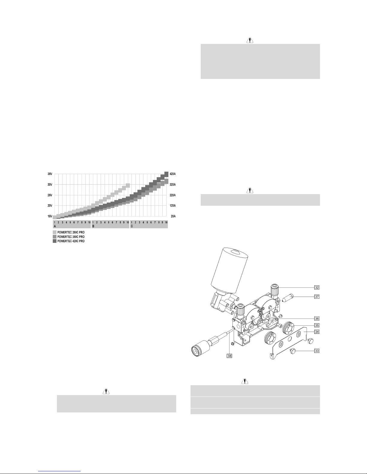
I-6
Spawanie metodą MIG/MAG w trybie
ręcznym
Dla rozpoczęcia procesu spawania metodą MIG/MAG w
trybie ręcznym należy:
• Włożyć wtyczkę przewodu sieciowego do gniazda
sieciowego.
• Załączyć zasilanie urządzenia wyłącznikiem
sieciowym [1] (powinien podświetlić się).
• Wprowadzić drut elektrodowy do uchwytu
spawalniczego używając przełącznika Test Drutu
[5].
• Sprawdzić przepływ gazu za pomocą przełącznika
Test Gazu [5].
• Pokrętło [17] ustawić w pozycji Manual (zapali się
lampka[15] informująca o pracy urządzenia w trybie
ręcznym).
• Stosownie do wybranego trybu pracy i grubości
spawanych elementów nastawić napięcie spawania
przełącznikami [3] i prędkość podawania drutu
elektrodowego pokrętłem [7]. Przy dobieraniu
nastaw moż
na posłużyć się poniższym wykresem.
• Zachowując właściwe zasady można przystąpić do
spawania.
Spawanie metodą MIG/MAG w trybie
synergicznym (automatycznym)
Dla rozpoczęcia procesu spawania metodą MIG/MAG w
trybie synergicznym należy:
• Włożyć wtyczkę przewodu sieciowego do gniazda
sieciowego.
• Załączyć zasilanie urządzenia wyłącznikiem
sieciowym [1] (powinien podświetlić się).
• Wprowadzić drut elektrodowy do uchwytu
spawalniczego używając przełącznika Test Drutu
[5].
• Sprawdź przepływ gazu za pomocą przełącznika
Test Gazu [5].
• Pokrętło wyboru średnicy drutu [16] ustawić w
pozycji odpowiadającej średnicy użytego drutu
elektrodowego.
• Pokrętło wyboru materiału spawanego i gazu [17]
ustawić w położeniu odpowiadającym użytym
materiałom.
UWAGA
Jeżeli wybrany proces spawania nie posiada trybu
synergicznego to na wyświetlaczu „A” pojawią się
trzy poziome kreski.
• Stosownie do wybranego trybu pracy i grubości
spawanych elementów nastawić napięcie spawania
przełącznikami Zmiany Napięcia Spawania [3].
UWAGA
W trybie pracy automatycznej urządzenie
samoczynnie dobiera właściwą prędkość podawania
drutu elektrodowego do każdej pozycji przełącznika
zmiany napięcia spawania [3]. Pokrętłem regulacji
prędkości [7] można tylko skorygować (±25%)
prędkość dobraną przez półautomat.
• Zachowując właściwe zasady można przystąpić do
spawania.
Wymiana rolek napędowych
Urządzenie fabrycznie jest wyposażone w rolki
napędowe do drutu elektrodowego o średnicy 1,0mm i
1,2mm. Jeżeli zachodzi konieczność spawania drutem
elektrodowym o innej średnicy należy zaopatrzyć się w
odpowiednie rolki napędowe (patrz rozdział Akcesoria) i
postępować zgodnie z poniższym opisem:
• Wyłączyć urządzenie z sieci zasilającej.
• Zwolnić ramiona dociskowe [32].
• Odkręcić śruby mocujące [33].
• Odchylić osłonę zabezpieczającą [34].
• Wymienić rolki napędowe [35] na zgodne z
zastosowanym drutem elektrodowym.
UWAGA
Do spawania drutami elektrodowymi o średnicy
większej niż 1,6mm należy dodatkowo wymienić:
• Prowadnice drutu konsoli podającej [36] i [37].
• Prowadnicę drutu gniazda EURO [38].
• Docisnąć osłonę zabezpieczającą [34] do rolek
napędowych.
• Całość skręcić śrubami mocującymi [33].
Konserwacja
UWAGA
W celu dokonania jakichkolwiek napraw lub czynności
konserwacyjnych zaleca się kontakt z najbliższym
serwisem lub firmą Lincoln Electric. Dokonywanie
napraw przez osoby lub firmy nieposiadające autoryzacji
spowoduje utratę praw gwarancyjnych.
Częstotliwość wykonywania czynności konserwacyjnych
może różnić się w zależności od środowiska, w jakim
urządzenie pracuje.
Page 75

I-7
Jakiekolwiek zauważone uszkodzenia powinny być
natychmiastowo zgłaszane.
Konserwacja podstawowa (codzienna)
• Sprawdzać stan kabli i poprawność połączeń.
Wymienić, jeśli to konieczne.
• Usuwać odpryski z dyszy gazowej uchwytu
spawalniczego. Rozpryski mogą przenosić się z
gazem osłonowym do łuku.
• Sprawdzać stan uchwytu spawalniczego.
Wymieniać go, jeśli to konieczne.
• Sprawdzać stan i działanie wentylatora
chłodzącego. Utrzymywać czyste otwory wlotu i
wylotu powietrza chłodzącego.
Konserwacja okresowa (po każdych 200
godzinach pracy, lecz nie rzadziej niż raz w
roku)
Wykonywać konserwację podstawową oraz, dodatkowo:
• Utrzymywać urządzenie w czystości. Wykorzystując
strumień suchego powietrza (pod niskim ciśnieniem)
usunąć kurz z części zewnętrznych obudowy i z
wnętrza spawarki.
• Sprawdzać i dokręcać wszystkie śruby.
UWAGA
Sieć zasilająca musi być odłączona od urządzenia przed
każdą czynnością konserwacyjną i serwisową. Po
każdej naprawie wykonać odpowiednie sprawdzenie w
celu zapewnienia bezpieczeństwa użytkowania.
Kompatybilność Elektromagnetyczna (EMC)
11/04
Urządzenie to zostało zaprojektowane zgodnie ze wszystkimi odnośnymi zaleceniami i normami. Jednakże może ono
wytwarzać zakłócenia elektromagnetyczne, które mogą oddziaływać na inne systemy takie jak systemy
telekomunikacyjne (telefon, odbiornik radiowy lub telewizyjny) lub systemy zabezpieczeń. Zakłócenia te mogą
powodować problemy z zachowaniem wymogów bezpieczeństwa w odnośnych systemach. Dla wyeliminowania lub
zmniejszenia wpływu zakłóceń elektromagnetycznych wytwarzanych przez to urządzenie należy dokładnie zapoznać się
zaleceniami tego rozdziału.
Urządzenie to zostało zaprojektowane do pracy w obszarze przemysłowym. Aby używać go w
gospodarstwie domowym niezbędne jest przestrzeganie specjalnych zabezpieczeń koniecznych do
wyeliminowania możliwych zakłóceń elektromagnetycznych. Urządzenie to musi być zainstalowane i
obsługiwane tak jak to opisano w tej instrukcji. Jeżeli stwierdzi się wystąpienie jakiekolwiek zakłóceń
elektromagnetycznych obsługujący musi podjąć odpowiednie dział
ania celem ich eliminacji i w razie potrzeby skorzystać
z pomocy Lincoln Electric. Nie dokonywać żadnych zmian w tym urządzeniu bez pisemnej zgody Lincoln Electric.
Przed zainstalowaniem tego urządzenia, obsługujący musi sprawdzić miejsce pracy czy nie znajdują się tam jakieś
urządzenia, które mogłyby działać niepoprawnie z powodu zakłóceń elektromagnetycznych. Należy wziąć pod uwagę:
• Kable wejściowe i wyjściowe, przewody sterujące i przewody telefoniczne, które znajdują się w, lub w pobliżu
miejsca pracy i urządzenia.
• Nadajniki i odbiorniki radiowe lub telewizyjne. Komputery lub urządzenia sterowane komputerowo
• Urządzenia systemów bezpieczeństwa i sterujące stosowane w przemyśle. Sprzęt służący do pomiarów i kalibracji.
• Osobiste urządzenia medyczne takie jak rozruszniki serca czy urządzenia wspomagające słuch.
• Sprawdzić odporność elektromagnetyczną sprzętu pracującego w, lub w miejscu pracy. Obs
ługujący musi być
pewien, że cały sprzęt w obszarze pracy jest kompatybilny. Może to wymagać dodatkowych pomiarów.
• Wymiary miejsca pracy, które należy brać pod uwagę będą zależały od konfiguracji miejsca pracy i innych
czynników, które mogą mieć miejsce.
Ażeby zmniejszyć emisję promieniowania elektromagnetycznego urządzenia należy wziąć pod uwagę następujące
wskazówki:
• Podłączyć urządzenie do sieci zasilającej zgodnie ze wskazówkami tej instrukcji. Jeśli mimo to pojawią się
zakłócenia, może zaistnieć potrzeba przedsięwzięcia dodatkowych zabezpieczeń takich jak np. filtrowanie napięcia
zasilania.
• Kable wyjściowe powinny być możliwie krótkie i ułożonym razem, jak najbliż
ej siebie. Dla zmniejszenia
promieniowania elektromagnetycznego, jeśli to możliwe należy uziemiać miejsce pracy. Obsługujący musi
sprawdzić czy połączenie miejsca pracy z ziemią nie powoduje żadnych problemów lub nie pogarsza warunków
bezpieczeństwa dla obsługi i urządzenia.
• Ekranowanie kabli w miejscu pracy może zmniejszyć promieniowanie elektromagnetyczne. Dla pewnych
zastosowań może to okazać się niezbędne.
Page 76

I-8
Dane Techniczne
POWERTEC 280C, 350C & 420C PRO:
PARAMETRY WEJŚCIOWE
Pobór mocy z sieci
280C PRO:
12 kVA @ 40% cykl pracy
350C PRO:
16 kVA @ 40% cykl pracy
Napięcie zasilania
230 / 400V ± 10%
3 - fazy
420C PRO:
21 kVA @ 40% cykl pracy
Częstotliwość
50 Hertz (Hz)
ZNAMIONOWE PARAMETRY WYJŚCIOWE PRZY 40°C
Cykl pracy
(oparty na 10 min. cyklu pracy)
Prąd wyjściowy Napięcie wyjściowe
280C PRO:
40%
60%
100%
280A
230A
175A
28.0 Vdc
25.5 Vdc
22.8 Vdc
350C PRO:
40%
60%
100%
350A
285A
220A
31.5 Vdc
28.2 Vdc
25.0 Vdc
420C PRO:
40%
60%
100%
420A
345A
265A
35.0 Vdc
31.3 Vdc
27.3 Vdc
ZAKRES PARAMETRÓW WYJŚCIOWYCH
Zakres prądu spawania Maksymalne napięcie stanu jałowego
280C PRO:
30A - 280A
280C PRO:
39 Vdc
350C PRO:
30A - 350A
350C PRO:
42 Vdc
420C PRO:
30A - 420A
420C PRO:
49 Vdc
ZALECANE PARAMETRY PRZEWODU I BEZPIECZNIKA ZASILANIA
Bezpiecznik lub wyłącznik nadprądowy Przewód zasilający
280C PRO:
32A zwłoczny (dla 230V)
20A zwłoczny (dla 400V)
280C PRO:
4 żyłowy, 4mm
2
350C PRO:
40A zwłoczny (dla 230V)
25A zwłoczny (dla 400V)
350C PRO:
4 żyłowy, 4mm
2
420C PRO:
63A zwłoczny (dla 230V)
32A zwłoczny (dla 400V)
420C PRO:
4 żyłowy, 6mm
2
WYMIARY
Waga
280C PRO:
142 kg
350C PRO:
147 kg
420C PRO:
157 kg
Wysokość
910 mm
Szerokość
565 mm
700 mm
(wersja wodna)
Długość
1030 mm
420C PRO:
(wodny)
183 kg
Temperatura pracy
-10°C to +40°C
Temperatura składowania
-25°C to +55°C
Page 77

1
Spare Parts, Parti di Ricambio, Ersatzteile, Lista de Piezas de
Recambio, Pièces de Rechange, Deleliste, Reserve
Onderdelen, Reservdelar, Wykaz Części Zamiennych
11/04
Part List reading instructions
• Do not use this part list for a machine if its code number is not listed. Contact the Lincoln Electric Service Department for
any code number not listed.
• Use the illustration of assembly page and the table below to determine where the part is located for your particular code
machine.
• Use only the the parts marked "X" in the column under the heading number called for in the assembly page (# indicate a
change in this printing).
Parti di Ricambio: istruzioni per la lettura
• Non utilizzare questa lista se il code della macchina non è indicato. Contattare l’Assistenza Lincoln Electric per ogni code
non compreso.
• Utilizzare la figura della pagina assembly e la tabella sotto riportata per determinare dove la parte è situata per il code
della vostra macchina.
• Usare solo le parti indicate con "X" nella colonna sotto il numero richiamato nella pagina assembly (# indica un cambio in
questa revisione).
Hinweise zur Verwendung der Ersatzteillisten
• Verwenden Sie diese Ersatzteilliste nicht für Geräte, nach deren code number diese Liste nicht gültig ist. Kontaktieren
Sie in diesem Fall die Ihnen bekannte Lincoln Service Station.
• Bestimmen Sie mit Hilfe der assembly page, der Stückliste und der code number Ihres Geräts, an welcher Stelle sich das
jeweilige Ersatzteil befindet.
• Ermitteln Sie zunächst mit Hilfe der assembly page die für die code number Ihres Geräts gültige Index-Spaltennummer,
und wählen Sie anschließend nur die Ersatzteile aus, die in dieser Spalte mit einem “X” markiert sind (das Zeichen #
weist auf eine Änderung hin).
Lista de piezas de recambio: instrucciones
• No utilizar esta lista de piezas de recambio, si el número de code no está indicado. Contacte con el Dpto. de Servicio de
Lincoln Electric para cualquier número de code no indicado.
• Utilice el dibujo de la página de ensamblaje (assembly page) y la tabla para determinar donde está localizado el número
de code de su máquina.
• Utilice sólo los recambios marcados con “X” de la columna con números según página de ensamblaje (# indica un
cambio en esta revisión).
Comment lire cette liste de pièces détachées
• Cette liste de pièces détachées ne vaut que pour les machines dont le numéro de code est listé ci-dessous. Dans le cas
contraire, contacter le Département Pièces de Rechange.
• Utiliser la vue éclatée (assembly page) et le tableau de références des pièces ci-dessous pour déterminer l'emplacement
de la pièce en fonction du numéro de code précis de la machine.
• Ne tenir compte que des pièces marquées d'un "X" dans la colonne de cette vue éclatée (# Indique un changement).
Instruksjon for deleliste
• Ikke bruk denne delelisten hvis code nummeret for maskinen ikke står på listen. Kontakt Lincoln Electric Serviceavd. for
maskiner med code utenfor listen.
• Bruk sprengskissen og pos. nr. på assembly page nedenfor for å finne de riktige delene til din maskin.
• Bruk kun de delene som er merket med "X" i den kolonnen som det henvises til på siden med assembly page (# indikerer
endring).
Leessinstructie Onderdelenlijst
• Gebruik deze onderdelenlijst niet voor machines waarvan de code niet in deze lijst voorkomt. Neem contact op met de
dichtstbijzijnde Lincoln dealer wanneer het code nummer niet vermeld is.
• Gebruik de afbeelding van de assembly page en de tabel daaronder om de juiste onderdelen te selecteren in combinatie
met de gebruikte code.
• Gebruik alleen de onderdelen die met een "X" gemerkt zijn in de kolom onder het model type op de assembly page (#
betekent een wijziging in het drukwerk).
Instruktion för reservdelslistan
• Använd inte denna lista för en maskin vars Code No inte är angivet i listan. Kontakta Lincoln Electric’s serviceavdelning
för Code No som inte finns i listan.
• Använd sprängskisserna på Assembly Page och tillhörande reservdelslista för att hitta delar till din maskin.
• Använd endast delar markerade med "X" i kolumnen under den siffra som anges för aktuellt Code No på sidan med
Assembly Page (# Indikerar en ändring i denna utgåva).
Wykaz części dotyczących instrukcji
• Nie używać tej części wykazu dla maszyn, których kodu (code) nie ma na liście. Skontaktuj się z serwisem jeżeli numeru
kodu nie ma na liście.
• Użyj ilustracji montażu (assembly page) i tabeli poniżej aby okreslić położenie części dla urządzenia z konkretnym kodem
(code).
• Użyj tylko częci z oznaczeniem “X” w kolumnie pod numerem głównym przywołującym stronę (assembly page) z
indeksem modelu (# znajdź zmiany na rysunku).
Page 78
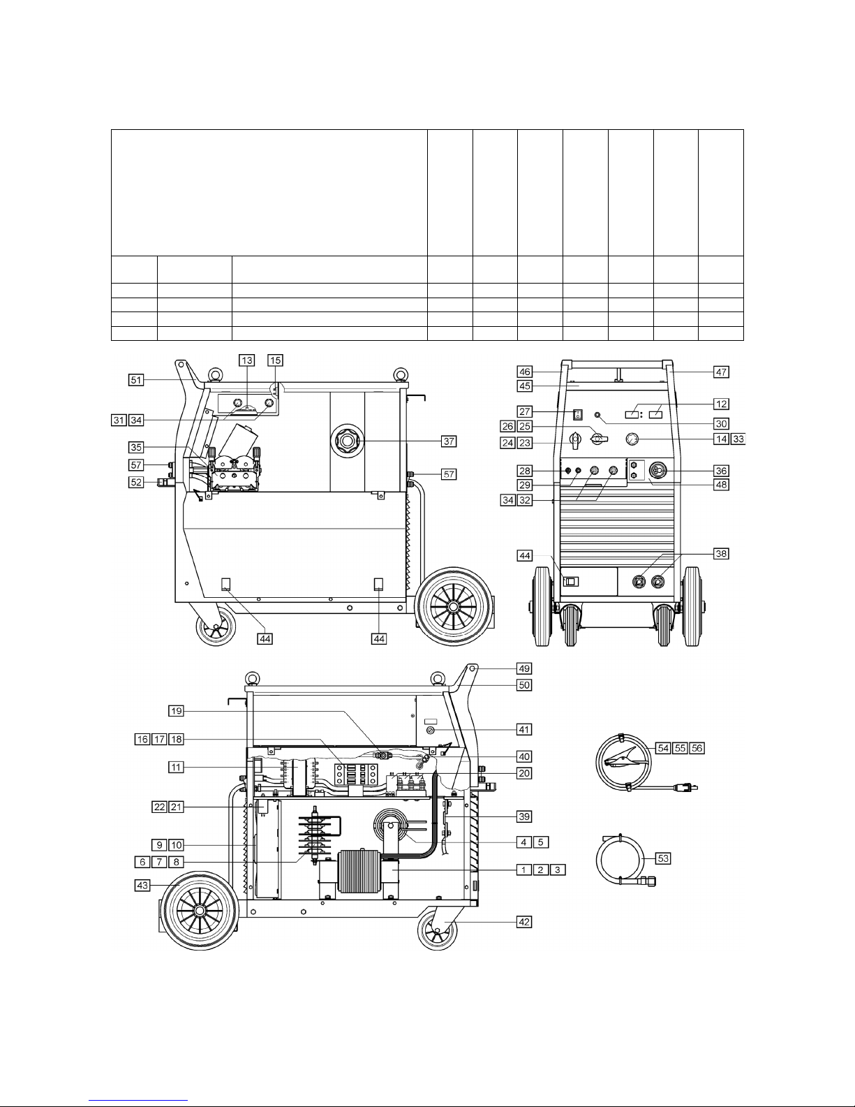
2
SP50019/50020/50021/50022 Rev. 1
07/03
POWERTEC 280C, 350C & 420C PRO
ASSEMBLY
PAGE NAME
Machine Assembly
Machine Assembly
(Rear side)
CODE
NO.:
K NO.: FIGURE NO.: A B
50019 K14013-1 POWERTEC 280C PRO 1 1
50020 K14014-1 POWERTEC 350C PRO 2 1
50021 K14015-1A POWERTEC 420C PRO 3 2
50022 K14015-2W POWERTEC 420C PRO (WATER) 4 3
Figure A
Page 79

3
Figure A: Machine Assembly
Item Description Part Number QTY 1 2 3 4 5 6
1 MAIN TRANSFORMER T1 B-4247-486-2R 1 X
yyy
2 MAIN TRANSFORMER T1 B-4247-484-2R 1
y
X
yy
3 MAIN TRANSFORMER T1 B-4247-485-2R 1
yy
XX
4 CHOKE L1 C-4244-383-2R 1 X
yyy
5 CHOKE L1 C-4244-383-4R 1
y
XXX
6 RECTIFIER SET V1 1156-112-069R 1 X
yyy
7 RECTIFIER SET V1 1156-112-070R 1
y
X
yy
8 RECTIFIER SET V1 1156-112-071R 1
yy
XX
9 FAN M1 1111-311-081R 1 X X
yy
10 FAN M1 0874-111-002R 1
yy
XX
11 AUXILIARY TRANSFORMER T2 C-4247-384-1R 1 X X X X
12 CONTROL P.C. BOARD G4560 C-3731-399-2R 1 X X X X
13 CONTROL P.C. BOARD US-67 C-3731-400-1R 1 X X X X
14 CONTROL P.C. BOARD PD-5 D-3731-465-1R 1 X X X X
15 RECTIFIER SET V2 1156-112-044R 1 X X X X
16 CONTACTOR K1 1115-212-177R 1 X
yyy
17 CONTACTOR K1 1115-212-178R 1
y
X
yy
18 CONTACTOR K1 1115-212-175R 1
yy
XX
19 GAS VALVE K2 0972-423-012R 1 X X X X
20 CAPACITORS C1,C2,C3 1158-121-010R 3 X X X X
21 CAPACITOR C4 1158-121-045R 1 X X
yy
22 CAPACITOR C4 1158-121-001R 1
yy
XX
23 VOLTAGE SWITCH S2 1115-260-166R 1 X
yyy
24 VOLTAGE SWITCH S2 1115-260-071R 1
y
XXX
25 VOLTAGE SWITCH S1 1115-260-167R 1 X
yyy
26 VOLTAGE SWITCH S1 1115-260-072R 1
y
XXX
27 MAIN SWITCH S3 1115-270-019R 1 X X X X
28 SWITCH S7 1158-650-021R 1 X X X X
29 SWITCH S6 1158-650-022R 1 X X X X
30 LAMP H1 0917-421-024R 1 X X X X
31 SWITCH S4,S5 1115-299-052R 2 X X X X
32 POTENTIOMETERS R11,R12 1158-113-304R 2 X X X X
33 KNOB 1158-910-041R 1 X X X X
34 KNOB 1158-910-038R 4 X X X X
35 FEEDING UNIT (complete) C-6713-007-1R 1 X X X X
36 EURO SOCKET (outlet guide) C-2985-006-1R 1 X X X X
37 SLEEVE 0744-000-192R 1 X X X X
38 SOCKET X2,X3 C-2986-001-2R 2 X X X X
39 SHUNT B1 0941-712-026R 1 X X X X
40 FERRITE TUBE 1158-290-001R 1 X X X X
41 FUSE F1 1158-660-087R 1 X X X X
42 TURNING WHEEL 1029-660-101R 2 X X X X
43 WHEEL 1029-660-250R 2 X X X X
44 HINGE 0654-610-004R 5 X X X X
45 EDGE SHIELD C-2687-031-1R 1 X X X X
46 LEFT HOLDER C-2687-026-1R 1 X X X X
47 RIGHT HOLDER C-2687-026-2R 1 X X X X
48 EURO SOCKET (insulator) C-2687-032-1R 1 X X X X
49 CAP C-2687-027-1R 2 X X X X
50 LEFT SIDE HANDLE ASSEMBLY C-2687-029-1R 1 X X X X
51 RIGHT SIDE HANDLE ASSEMBLY C-2687-029-2R 1 X X X X
52 SMALL FLAP C-2687-025-1R 1 X X X X
53 GAS HOSE -2m D-5578-174-1R 1 X X X X
54 GROUND CABLE with WORK CLAMP -3m K14011-1 1 X
yyy
55 GROUND CABLE with WORK CLAMP -3m K14018-1 1
y
X
yy
56 GROUND CABLE with WORK CLAMP -3m K14019-1 1
yy
XX
57 QUICK CONNECT COUPLING (ONLY
WATER)
0744-000-151R 4
yyy
X
Page 80

4
Figure B
Figure B: Machine Assembly (Rear side)
Item Description Part Number QTY 1 2 3 4 5 6
1 HANDLE 0561-230-005R 1 X X X
2 GAS INLET SOCKET D-1891-135-1R 1 X X X
3 MAINS CORD without PLUG -5m (4x4mm2) D-5578-171-2R 1 X
yy
3 MAINS CORD without PLUG -5m (4x6mm2) D-5578-171-3R 1
y
XX
4 CIRCUIT BREAKER Q1 (ONLY WATER) 1115-299-027R 1
yy
X
5 SOCKET X16 (ONLY WATER) 1131-222-004R 1
yy
X
6 WATER COOLER (ONLY WATER) K10329 1
yy
X
7 COOLER BRACKET (ONLY WATER) D-2632-641-1R 1
yy
X
Page 81

5
Electrical Schematic, Schema Elettrico, Elektrische
Schaltpläne, Esquema Eléctrico, Schéma Electrique, Elektrisk
Skjema, Elektrisch Schema, Elektriskt Kopplingsschema,
Schemat Elektryczny
Page 82

6
Page 83

7
Page 84

8
Accessories, Accessori, Zubehör, Accesorios, Accessoires,
Tilleggsutstyr, Accessores, Tillbehör, Akcesoria
KP14017-0.8 Drive roll kit solid wire (0.6 / 0.8)
Kit rulli per filo pieno (0.6 / 0.8)
Drahtvorschubrollen-Satz für Massiv-Draht (0.6 / 0.8)
Kit rodillo de arrastre hilo macizo (0,6 / 0,8)
Galet d’entraînement de fil et guide fil 0.6-0.8mm
Matehjulsett stål 0,6/0,8mm
Set draadaanvoerrol massieve draad (0.6/0.8)
Drivhjulsats för homogentråd (0.6 / 0.8)
Rolka V0.6/V0.8
KP14017-1.0 Drive roll kit solid wire (0.8 / 1.0)
Kit rulli per filo pieno (0.8 / 1.0)
Drahtvorschubrollen-Satz für Massiv-Draht (0.8 / 1.0)
Kit rodillo de arrastre hilo macizo (0,8 / 1,0)
Galet d’entraînement de fil et guide fil 0.8-1.0mm
Matehjulsett stål 0,8/1,0mm
Set draadaanvoerrol massieve draad (0.8/1.0)
Drivhjulsats för homogentråd (0.8 / 1.0)
Rolka V0.8/V1.0
KP14017-1.2 Drive roll kit solid wire (1.0 / 1.2)
Kit rulli per filo pieno (1.0 / 1.2)
Drahtvorschubrollen-Satz für Massiv-Draht (1.0 / 1.2)
Kit rodillo de arrastre hilo macizo (1,0 / 1,2)
Galet d’entraînement de fil et guide fil 1.0-1.2mm
Matehjulsett stål 1,0/1,2mm
Set draadaanvoerrol massieve draad (1.0/1.2)
Drivhjulsats för homogentråd (1.0 / 1.2)
Rolka V1.0/V1.2
KP14017-1.6 Drive roll kit solid wire (1.2 / 1.6)
Kit rulli per filo pieno (1.2 / 1.6)
Drahtvorschubrollen-Satz für Massiv-Draht (1.2 / 1.6)
Kit rodillo de arrastre hilo macizo (1,2 / 1,6)
Galet d’entraînement de fil et guide fil 1.2-1.6mm
Matehjulsett stål 1,2/1,6mm
Set draadaanvoerrol massieve draad (1.2/1.6)
Drivhjulsats för homogentråd (1.2 / 1.6)
Rolka V1.2/V1.6
KP14017-1.2A Drive roll kit aluminium wire (1.0 / 1.2)
Kit rulli per filo in alluminio (1.0 / 1.2)
Drahtvorschubrollen-Satz für Aluminium-Draht (1.0 / 1.2)
Kit rodillo de arrastre hilo aluminio ( 1,0 / 1,2)
Galet d’entraînement de fil (aluminium) et guide fil 1.0-1.2mm
Matehjulsett aluminium 1,0/1,2mm
Set draadaanvoerrol aluminiumdraad (1.0/1.2)
Drivhjulsats för aluminiumtråd (1.0 / 1.2)
Rolka U1.0/U1.2
KP14017-1.6A Drive roll kit aluminium wire (1.2 / 1.6)
Kit rulli per filo in alluminio (1.2 / 1.6)
Drahtvorschubrollen-Satz für Aluminium-Draht (1.2 / 1.6)
Kit rodillo de arrastre hilo aluminio ( 1,2 / 1,6)
Galet d’entraînement de fil (aluminium) et guide fil 1.2-1.6mm
Matehjulsett aluminium 1,2/1,6mm
Set draadaanvoerrol aluminiumdraad (1.2/1.6)
Drivhjulsats för aluminiumtråd (1.2 / 1.6)
Rolka U1.2/U1.6
KP14017-1.6R Drive roll kit cored wire (1.2 / 1.6)
Kit rulli per filo animato (1.2 / 1.6)
Antriebsrollen-Satz Fülldraht (1.2 / 1.6)
Kit rodillo de arrastre hilo tubular (1.2 / 1.6)
Kit galet fil fourré (1.2 / 1.6)
Matehjulsett seraterte matehjul (1,2/1,6)
Set draadaanvoerrol gevulde draad (1.2 / 1.6)
Drivhjulsats för rörtråd (1.2 / 1.6)
Rolka radełkowana 1.2/1.6
Page 85

9
KP14017-2.4R Drive roll kit cored wire (1.6 / 2.4)
Kit rulli per filo animato (1.6 / 2.4)
Antriebsrollen-Satz Fülldraht (1.6 / 2.4)
Kit rodillo de arrastre hilo tubular (1.6 / 2.4)
Kit galet fil fourré (1.6 / 2.4)
Matehjulsett seraterte matehjul (1,6/2,4)
Set draadaanvoerrol gevulde draad (1.6 / 2.4)
Drivhjulsats för rörtråd (1.6 / 2.4)
Rolka radełkowana 1.6/2.4
K14009-1 CO2 Socket Kit
Kit per presa CO2
CO2 Stecker-Satz
Kit zócalo calentador CO2
Kit prise CO2
CO2 tilkoblingskit
CO2 aansluitset
CO2 kontaktkit
KIT gniazda podgrzewacza gazu
 Loading...